low temperature effects on the mechanical, fracture, and
TRANSCRIPT

University of Rhode Island University of Rhode Island
DigitalCommons@URI DigitalCommons@URI
Mechanical, Industrial & Systems Engineering Faculty Publications Mechanical, Industrial & Systems Engineering
5-2020
Low Temperature Effects on the Mechanical, Fracture, and Low Temperature Effects on the Mechanical, Fracture, and
Dynamic Behavior of Carbon and E-glass Epoxy Laminates Dynamic Behavior of Carbon and E-glass Epoxy Laminates
James LeBlanc
Paul Cavallaro
Jahn Torres
David Ponte
Eric Warner
See next page for additional authors
Follow this and additional works at: https://digitalcommons.uri.edu/mcise_facpubs

Authors Authors James LeBlanc, Paul Cavallaro, Jahn Torres, David Ponte, Eric Warner, Ryan Saenger, Irine Neba Mforsoh, and Aun Shukla

Original Article
Low temperature effects on the mechanical, fracture, and dynamicbehavior of carbon and E-glass epoxy laminates
James LeBlanc a, *, Paul Cavallaro a, Jahn Torres a, David Ponte a, Eric Warner a,Ryan Saenger a, Irine Neba Mforsoh b, Arun Shukla b
a Naval Undersea Warfare Center (Division Newport), 1176 Howell St, Newport, RI, 02841, USAb Dynamic Photo Mechanics Laboratory, Department of Mechanical, Industrial and Systems Engineering, University of Rhode Island, Kingston, RI, 02881,USA
a r t i c l e i n f o
Article history:Received 2 April 2020Received in revised form12 May 2020Accepted 13 May 2020Available online 22 May 2020
Keywords:Composite materialLow temperatureMechanical characterizationWater absorptionFracture
a b s t r a c t
An experimental investigation through which the effects of low temperatures on the mechanical, frac-ture, impact, and dynamic properties of carbon- and E-glass-epoxy composite materials has been con-ducted. The objective of the study is to quantify the influence of temperatures from 20 �C down to �2 �Con the in-plane (tensile/compressive) and shear material properties, static and dynamic Mode-I fracturecharacteristics, impact/residual strength, and the storage and loss moduli for the materials considered.The low end of the temperature range considered in the study is associated with Arctic seawater as wellas conditions found at extreme ocean depths (2 �Ce4 �C). In the investigation, both carbon/epoxy and E-glass/epoxy laminates are evaluated as these materials are of keen interest to the marine and underseavehicle community. The mechanical characterization of the laminates consists of controlled tension,compression, and short beam shear testing. The Mode-I fracture performance is quantified under bothquasi-static and highly dynamic loading rates with additional flexure after impact strength character-ization conducted through the use of a drop tower facility. Finally, dynamic mechanical analysis (DMA)testing has been completed on each material to measure the storage and loss moduli of the carbon fiber-and E-glass fiber reinforced composites. The findings of the study show that nearly all characteristics ofthe mechanical performance of the laminates are both material and temperature dependent.© 2020 The Authors. Production and hosting by Elsevier B.V. on behalf of KeAi Communications Co., Ltd.This is an open access article under the CC BY-NC-ND license (http://creativecommons.org/licenses/by-
nc-nd/4.0/).
1. Introduction
A key advantage to the use of fibrous composites in structuraldesign is the ability to customize material performance to pre-scribed design requirements and operating environments. Fiber-reinforced polymer (FRP) composites provide many readily recog-nized performance benefits; lightweight, high strength- andstiffness-to-weight ratios, corrosion resistance, net shapemanufacturing, and more. Proper selections of the fabric architec-tures, fiber and matrix materials, ply stacking arrangements, etc.can yield significant mechanical performance advantages overtraditional structural materials. Owing to the significant
mechanical performance advantages that can be achieved beyondtraditional homogeneous and isotropic materials, the marine in-dustries utilize FRP composites in various surface and sub-surfaceapplications. Composite material selections are often made basedupon empirical data derived from material level tests, prototypeexperiments, and/or analytical/computational mechanics modelsfor the required operating conditions. However, when operatingenvironments and loading conditions of systems change beyondtheir original intended use, reevaluation is generally required toensure continued functionality and structural integrity. Consider-ation is made that subsea systems in use in applications such asdeep-sea mining or Arctic drilling may not have been originallydesigned for operations in such low temperature environments.Furthermore, with a consideration of the complexities of compositematerials, the community has a limited understanding of failureand fracture mechanisms of FRP composites operating in coldtemperature environments. Compared to traditional materials such
* Corresponding author.E-mail address: [email protected] (J. LeBlanc).Peer review under responsibility of Editorial Board of International Journal of
Lightweight Materials and Manufacture.
Contents lists available at ScienceDirect
International Journal of Lightweight Materials and Manufacture
journal homepage: https: / /www.sciencedirect .com/journal /internat ional- journal-of- l ightweight-mater ia ls-and-manufacture
https://doi.org/10.1016/j.ijlmm.2020.05.0022588-8404/© 2020 The Authors. Production and hosting by Elsevier B.V. on behalf of KeAi Communications Co., Ltd. This is an open access article under the CC BY-NC-NDlicense (http://creativecommons.org/licenses/by-nc-nd/4.0/).
International Journal of Lightweight Materials and Manufacture 3 (2020) 344e356

as metals, there is generally a limited understanding of the me-chanical and failure/fracture mechanisms of complex compositestructures operating in cold environments. Understanding theseenvironmental influences is critical towards the: (1) improvementof fiber and matrix material performance, (2) development ofdamage and fracture resistant laminate designs, and (3) progress innew manufacturing processes necessary to meet the challenges ofoperation in cold environments.
Many polymers exhibit increased stiffness and decreasedtoughness with colder temperatures. Therefore, the potential forunanticipated failure mechanisms to occur with environmentally-dependent material properties is problematic for polymer com-posites at extreme temperatures. These factors can reduce struc-tural integrity and lead to premature and catastrophic structuralfailures in low temperature settings. Therefore, material consider-ations in the design of composite structures subject to cold oper-ating environments require an in-depth understanding of therelationships between laminate stress distributions, ply interfacemechanics, hygrothermal behaviors, damage mechanisms, andfracture mechanics. Improving fracture toughness of FRP compos-ites is of greater importance when loading events including impact,wave slap, and implosion may occur in cold environments. Char-acterizing the effects of cold temperatures on static and dynamicfracture toughnesses using analytical work and controlled labora-tory results aids in sensible decision making when consideringmaterial selection. Comprehensive knowledge of the effects oftemperature on the failure response of FRP composites beyondwhat is currently known will greatly advance the ability to designand implement future marine based systems.
Variations between fiber and matrix thermal expansionsresulting from elevated curing temperature transitioning toambient temperatures followed by cold operating temperaturescan produce damaging residual interlaminar shear stresses andmicrocracking e even in the absence of applied external loads.Thermally-induced debonding of the fiber-matrix occurs when theinterlaminar shear stresses exceed the shear strength of the matrixcausing the formation of microcracks. Repeated cold temperaturecycles can lead to coalescence of microcracks to the extent thatlarger interlaminar and intralaminar cracks develop and degradelaminate strength and stiffness levels.
Studies of temperature effects on FRP composites have beenlimited [1]. Kichhannagari [2] observed from experiments thatmicro-cracking was more pronounced at cold versus ambienttemperatures when specimens were tested under nominal uniaxialand biaxial loads. Thermal contraction causes matrix shrinkage andforms residual interlaminar shear stresses. These stresses degradethe interlaminar shear strength, fatigue life, and laminate stiffness.Microcracks can lead to increased permeability, creating paths forhygrothermal effects [3e5] such as moisture and fluid absorptionand swelling at cold temperatures. Swelling is a major source ofenvironmentally-induced stress when laminates are subjected to afreeze-thaw cycling in the presence of water. The generation ofmicrocracks can lead to coalescence which can cause largermesoscale and macro-scale cracks leading to reductions in fracturetoughness and damage tolerance. The effects of freeze-thaw cycleswhen combined with loading cycles are of significant importanceandmust be addressed in the design of low temperature structures.Improving fracture toughness of FRP composites is of greaterimportance when dynamic and impact loading events occurring incold ocean environments are a concern. Controlled laboratory ex-periments such as drop tower testing can be performed to simulatethese events bywhich the effects of cold temperatures on static anddynamic fracture toughness can be characterized for optimizingmaterial selections in design. Lopresto et al. [6] investigated theeffects of extreme low temperatures, as well as the underlying
support conditions, on the compression after impact behavior ofcomposite laminates and identified the effects of water backingduring impact. The same authors have also presented findings ofthe effect of extreme low temperatures on the impact behavior ofbasalt laminates, including damage onset conditions and energyabsorption by the laminates [7].
2. Materials
The materials studied in the investigation consisted of carbon/epoxy and E-glass/epoxy laminates. In each laminate the base fabricwas a “plain weave” style in which the yarns are woven in a one-over one-under pattern as shown in Fig. 1. This resulted in abalanced fabric in the warp and weft directions. The E-glass fabrichad an areal weight density of 190 g/m2 (5.61 oz/yd2), yarn count of18 in the warp and fill directions, and was in a greige (untreated)condition. The carbon fabric was designated as S 611 which had anareal weight density of 199 g/m2 (5.88 oz/yd2), yarn counts of 12.5in each direction, and was also in the greige condition. The panelswere manufactured in a press to maintain uniform thickness andutilized ProSet 125/226 laminating epoxy. They were cured in thepress at 82 �C (180 �F), under 14 tons of pressure. To support thevarious testing requirements, panels of thicknesses of 2.54 and5.08 mm (0.1 and 0.2 in.) were manufactured.
3. Experimental approach
3.1. Tension/compression/short beam shear
Material characterization in the form of Tension, Compression,and Short Beam Shear was conducted on the carbon and E-glasslaminates to determine the effect of decreasing temperature on thestiffness and strength properties. Mechanical testing was con-ducted in accordance with ASTM D638 (Tension) [9], ASTM D3410(Compression) [10], and ASTM D2344 (Short Beam) [11], respec-tively. Each material was characterized for both stiffness andstrength at temperatures of 20 �C, 5 �C, and �2 �C. The tests wereperformed on an Instron® machine operated in displacement-controlled loading, with the low-temperature conditions achievedin an environmental chamber utilizing liquid nitrogen as thecooling source. Prior to the conduct of all tests the specimens wereplaced in the environmental chamber at temperature for a mini-mum of 2 h to ensure uniform temperature through the specimen.This was deemed sufficient due to the relative thinness of thespecimens. Fig. 2 provides the details of the respective experi-mental test arrangements.
Fig. 1. Plain weave fabric architecture (courtesy of JPS composites technical referencehandbook [8]).
J. LeBlanc et al. / International Journal of Lightweight Materials and Manufacture 3 (2020) 344e356 345

3.2. Static Mode I fracture
Static Mode-I fracture tests were conducted to measure thetemperature dependence on the critical strain energy release ratesGIC for the carbon and E-glass laminates. The Mode-I fracture testswere performed at 20 �C, 5 �C, and�2 �C to ensure consistency withthemechanical characterization. Specimens were double cantileverbeam (DCB) type and fracture gages were bonded to the specimenedges to measure the crack lengths, crack growth stability, andallow calculation of GIC. DCB specimens were 22.80 cm long by2.54 cm wide (9 in. by 1 in.) and included a 7.62 cm (3 in.) Tefloninsert positioned at the mid-plane to serve as a precrack. Singlecrack gages consisting of 20 strands oriented perpendicularly to thecrack front with a strand spacing of 2 mm (0.08 in.) were bonded toone side of each specimen. As the crack front propagated acrosseach strand, the strands broke consecutively and the change in gageresistance was recorded by the data acquisition system. Addition-ally, the load and deflection time histories were recorded by the testmachine. Using the time history data, crack growth and GIC valueswere characterized.
Upon loading, strain energy is produced in the specimen and acritical load Pc is reached. At this load, the corresponding strainenergy causes crack initiation to occur at the end of the Teflon
insert. As the deflection of each beam increases further, increases incrack length occur, strain energy is released (lost) and compliance isincreased. The load versus deflection curve for the �2 �C E-glassfracture test is shown in Fig. 3 and was representative of the DCBMode-I fracture test specimen behavior of all samples tested. Strainenergy released through Mode-I fracture was calculated bycontinually monitoring the loads and deflections for each cracklength prior to the next increment of crack growth. The method ofcalculating GIC in the current study is the Modified Beam Theory(MBT) approach. The governing MBT equation is given as [13]:
GIC ¼3Pd2wa
where P is the load, d is the extension,w is the specimenwidth, anda is the crack length.
3.3. Dynamic Mode I fracture
The dynamic fracture characteristics of the carbon and E-glasslaminates were obtained using an advanced experimentalapproach [14]. Dynamic fracture toughness was determined usingthe wedge-insert-fracture method, which utilized a double
Fig. 2. Tensile, compressive, and short beam shear test setups.
Fig. 3. Mode-I fracture test configuration and typical load vs. extension behavior.
J. LeBlanc et al. / International Journal of Lightweight Materials and Manufacture 3 (2020) 344e356346

cantilever beam specimen geometry combined with a unique SplitHopkinson Pressure Bar (SHPB) setup shown in Fig. 4. The specimenhad a width of 12.70 mm (0.5 in.) and a thickness of 5.08 mm (0.2in.) with a Teflon film insert used as a precrack at the mid plane ofthe panel. The incident bar was 9.5 mm (0.375 in.) in diameter,162 cm (64 in.) in length and was made out of brass. The portion ofthe wedge insert in contact with the incident bar had a 12.7 mm(0.5 in.) outer diameter and the flat end in contact with the speci-mens was semi-cylindrical with a diameter of 3 mm (0.118 in.). Theinitial crack length (distance from the center of the semi-cylindricaltip of the inserted wedge to the crack tip), was 4.7 cm (1.85 in.) and4.2 cm (1.65 in.) for the carbon/epoxy composite and E-glass/epoxycomposite, respectively.
During each experiment, the striker bar driven by a gas gunimpacted the incident bar creating a compressive pulse in the barwhich was measured using two resistive strain gages bonded onthe incident bar, opposite to each other. At the point of contact, theimpact force is resolved into two components, Fx and Fy, as seen inFig. 4. A strain gage was bonded to the upper surface of the spec-imen with its center at the point (x, y) ¼ (0, h). This strain gagemeasured the surface strains which were used for the estimation ofthe vertical component of the impact force, Fy and subsequently forthe calculation of the dynamic critical energy release rate, GICd. Thecomponent of the energy release rate related to the horizontalcomponent of the force, Fx was neglected because the radius of
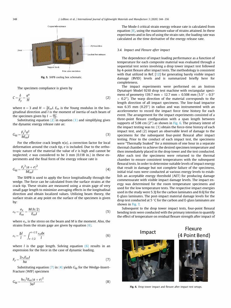
wedge tip was very small compared to the initial crack length.During the experiment, the end of the specimen without a crackrested on a support block and the crack opening was ensured to besymmetrical. The experiments conducted at 5 �C and�2 �C utilizeda wooden cooling box with glass fiber insulation as shown in Fig. 5.Compressed air circulated in a copper tube, immersed in dry ice,was used to cool the specimen in the cooling box. The desiredspecimen temperatures were achieved by controlling the flow rateof the compressed air with real-time measurements of the tem-perature in the box recorded using a K-type thermocouple. Uponthe specimen reaching thermal equilibrium with the air in thecooling chamber, the striker was released to create the compressivepulse in the incident bar. Clay was used as a pulse shaper on thestriker end of the incident bar to eliminate the high frequencycomponents of the compressive pulse, thus effectively suppressingvibrations on the specimens caused by impact loading.
The dynamic energy release rate for the Mode-I Dynamic DCBspecimen is given by:
GId ¼Fy2
2bvCva
(1)
where Fy is the vertical component of the force, b is thewidth of thespecimens, a is the initial crack length and C is the compliance ofthe specimen.
Fig. 4. Dynamic Mode-I fracture setup using Split Hopkinson Pressure Bar.
J. LeBlanc et al. / International Journal of Lightweight Materials and Manufacture 3 (2020) 344e356 347
The specimen compliance is given by
C¼ d
Fy¼ an
H(2)
where n ¼ 3 and H ¼ 32ExxI. Exx is the Young modulus in the lon-
gitudinal direction and I is the moment of inertia of each beam ofthe specimen given by I ¼ bh3
12 .Substituting equation (2) in equation (1) and simplifying gives
the dynamic energy release rate as:
GId ¼Fy2a2
bExxI(3)
For the effective crack length n(a), a correction factor for localdeformation around the crack tip, e is included. Due to the ortho-tropic nature of the material the value of e is high and cannot beneglected; e was considered to be 3 mm (0.118 in.) in these ex-periments and the final form of the energy release rate is
GId ¼Fy2ðaþ eÞ2
bExxI(4)
The SHPB is used to apply the force longitudinally through thewedge. The force can be calculated from the surface strains at thecrack tip. These strains are measured using a strain gage of verysmall gage length to minimize averaging effects in the longitudinaldirection and obtain localized values. Utilizing beam theory, thesurface strain at any point on the surface of the specimen is givenby:
εx ¼ sxExx
¼ Mðh=2ÞExxI
(5)
where sx, is the stress on the beam and M is the moment. Also, thestrains from the strain gage are given by equation (6).
εs¼Dll¼
Z eþl=2
e�l=2
εxdxl
(6)
where l is the gage length. Solving equation (6) results in anexpression for the force in the case of dynamic loading.
Fy ¼2εsExxIha
(7)
Substituting equation (7) in (4) yields GId for the Wedge-Insert-Fracture (WIF) specimen
GId ¼hεs2Exxðaþ eÞ2
3a2(8)
The Mode-I critical strain energy release rate is calculated fromequation (8), using the maximum value of strains attained. In theseexperiments and in lieu of using the strain rate, the loading ratewascalculated as the time derivative of the energy release rate.
3.4. Impact and Flexure after impact
The dependence of impact loading performance as a function oftemperature for each composite material was evaluated through asequential test series involving a drop tower impact test followedby 4-point flexure after impact tests. Themethodology is consistentwith that utilized in Ref. [12] for generating barely visible impactdamage (BVID) levels and is summarized briefly here forcompleteness.
The impact experiments were performed on an InstronDynatup® Model 9210 drop test machine with rectangular speci-mens of geometry 139.7 mm � 12.7 mm � 0.508 mm (5.500 � 0.500
� 0.200). The warp direction of the material corresponds to thelength direction of all impact specimens. The line-load impactorwas 6.35 mm (0.2500) in radius and was instrumented with anaccelerometer to record the impact force time history for eachevent. The arrangement for the impact experiments consisted of athree-point flexure configuration with a span length betweensupports of 5.08 cm (200) as shown in Fig. 6. The primary intent ofthe impact testing was to: (1) obtain the force-time history of eachimpact test, and (2) impart an observable level of damage to thespecimens for the subsequent four-point flexural after impacttesting. Prior to the conduct of each impact test, the specimenswere “Thermally Soaked” for a minimum of one hour in a separatethermal chamber to achieve the desired specimen temperature andthen immediately placed in the drop tower and the test conducted.After each test the specimens were returned to the thermalchamber to ensure consistent temperatures with the subsequentflexural tests. In order to determine suitable levels of impact energythat result in damage but not complete failure of the specimens,initial trial runs were conducted at various energy levels to estab-lish an acceptable energy threshold (AET) for producing damagecommensurate with visible impact damage levels. The impact en-ergy was determined for the room temperature specimens andused for the low temperature tests. The respective impact energiesused in the study were 5.3J for the carbon laminates and 8.6J for theE-glass laminates. The post-impact material damage levels for thedrop test conducted at 5 �C for the carbon and E-glass laminates areshown in Fig. 7.
Subsequent to the drop tower impact tests, four-point flexuralbending tests were conductedwith the primary intention to quantifythe effect of temperature on residual flexure strength after impact of
Fig. 5. SHPB cooling box schematic.
Fig. 6. Drop tower impact and flexure after impact test setups.
J. LeBlanc et al. / International Journal of Lightweight Materials and Manufacture 3 (2020) 344e356348

the respective laminates. In a consistent manner with the tensile andcompression testing previously discussed, the four-point flexureloading was performed on the Instron test machine with a lowtemperature environmental chamber installed to ensure consistenttemperature for the duration of the tests. A four-point flexure-loading fixture with cylindrical steel rollers as shown in Fig. 6 wasused for the characterization. The overall span length for the testswas 114.3 mm and the span between loading supports was 38.1 mm.
3.5. DMA
The storage and loss moduli of the carbon and E-glass laminateswere characterized through the use of Dynamic Mechanical Anal-ysis (DMA). Dynamic mechanical analysis is based on the applica-tion of small-amplitude, time-oscillatory mechanical forcing to amaterial sample and the simultaneous measurement of displace-ment, force magnitude and phase. In this study, the perturbationsare applied by a displacement-controlled drive shaft that bends thespecimen. Although the materials in this study are not isotropic,normal strain parallel to the specimen's neutral axis is the domi-nant deformation mode in beam bending. The specimens weresmall beams 5.6mm (0.22 in.) wide and 35.5mm (1.4 in.) long and aTA Q800 DMA machine with a 20 mm dual-cantilever clamp wasutilized as shown in Fig. 8. The composite sample beams wereexcited by time-oscillatory loads between 1 and 100 Hz at tem-peratures from �100 �C to 180 �C, a range that includes the glasstransition temperature, Tg. A time-temperature superpositiontechnique enabled estimation of the high-frequency storage andloss moduli of the composite specimens. All mechanical propertiesmeasured by DMA in this study are measured in the weft direction.
The tangent of the phase between stress and strain is a measure ofthe ratio of the loss modulus of the material to its storage coun-terpart; tan d ¼ Imð~EÞ=Reð~EÞ [15].
A number of specimens were preliminarily characterized byloading them in tension (x-direction) in order to measure the smallstrain as a function of stress at a number of frequencies (1 Hz,10.8 Hz, 100 Hz, and 200 Hz). At all strain rates and strain levelsunder 0.075% the composites exhibited an elastic modulus of4.9 GPa and 9.17 GPa for the E-glass and carbon composite,respectively. Fig. 9 shows that the linear viscoelastic behavior atsmall strains is a matrix dominated behavior with a composite(fiber and matrix combined) behavior emerging at higher strainrates at strain levels greater than 0.075%. The carbon laminatesexhibit this behavior transition at a lower strain level than that seenin the E-glass laminates. Note the increasingly dissipative nature ofthe carbon laminates at strain levels approaching 0.1% at a rootmean-squared (RMS) strain rate of 0.7 rad/s. Therefore, at this levelof strain and strain rates the carbon laminate's stress state is his-tory-dependent.
4. Experimental results
4.1. Mechanical characterization
The tensile and compressivemechanical characterization resultsfor the carbon and E-glass tests conducted at 20 �C, 5 �C, and �2 �Care shown in Fig. 10 and summarized in Table 1 and Table 2. In allcases, the individual tests showed that material response is nearlylinear up to failure and the failure was classified as brittle in naturesuch that there was minimal plastic response as shown in Fig. 11.From the presented results there are evident trends in materialresponse over the temperature range considered in the study. Theexperimental results show that in terms of stiffness performance,both the carbon and E-glass laminates are significantly stiffer intension that compression. For the carbon laminates there is a dif-ference of nearly an order of magnitude and for the E-glass lami-nates the compressive stiffness is 25% of that of the tensile.
The tensile results showed that the carbon laminates wereabout five times stiffer on average than the E-glass laminatesacross all temperatures, 58.6 GPa vs. 11.3 GPa (8500 ksi vs. 1645ksi), and had slightly more than double the strength of the E-glasslaminates. Furthermore, the E-glass laminates did not demon-strate a significant dependence on decreasing temperature acrossthe range considered. It should be noted that the mechanical re-sults presented considered in this section are laminate represen-tative properties (fiber and matrix contributions) versus DMA
Fig. 7. 5 �C impact test damage levels.
Fig. 8. Dual-cantilever clamp and deflection boundary conditions.
J. LeBlanc et al. / International Journal of Lightweight Materials and Manufacture 3 (2020) 344e356 349

results, which are presented later, are primarily representative ofthe matrix material. Both the tensile modulus and tensile strengthwere statistically equal at each temperature ranging from 20 �Cto �2 �C. Conversely, The carbon laminates exhibit a dependence
on the test temperature in that under tension these laminatesbecame both stiffer and stronger as the temperature decreasedfrom 20 �C to �2 �C. The modulus displayed an 11% increase andthe strength displayed a 7% increase over the temperature range,
Fig. 9. Stress-strain behavior of E-glass and carbon laminates showing both elastic (left axes) and viscous (right axes) stresses.
Fig. 10. Tensile and compressive mechanical characterization.
Table 1E-Glass mechanical property summary.
E-Glass
20 �C 5 �C �2 �C
Tensile Modulus (GPa) 11.39 ± 0.40 11.34 ± 0.26 11.51 ± 0.20Compressive Modulus (GPa) 2.47 ± 0.18 1.83 ± 0.25 1.84 ± 0.06Tensile Strength (MPa) 288.31 ± 16.18 288.08 ± 13.38 293.48 ± 10.86Compressive Strength (MPa) 154.21 ± 9.07 160.06 ± 7.76 165.49 ± 9.39Short Beam Shear Strength (MPa) 27.73 ± 1.36 33.26 ± 0.87 33.76 ± 0.76
J. LeBlanc et al. / International Journal of Lightweight Materials and Manufacture 3 (2020) 344e356350

hence an inverse relationship between tensile performance andtemperature.
In compression, there are several trends that were identified.Specific to the compressive behavior, the carbon laminates wereapproximately two times stiffer than the E-glass laminates acrossall temperatures. The carbon laminates had approximately 2.5times the compressive strength of the E-glass laminates across thetemperature range. The specific E-glass/epoxy laminates utilized inthis study exhibited differing trends in moduli and strength withdecreasing temperature. As evidenced from Fig. 10, it was seen thatwith decreasing temperature there was a decrease in compressivemodulus but a corresponding increase in compressive strength. Inother words, as the temperature was reduced, the material becamesofter but stronger. The carbon/epoxy laminates exhibited a cleartrend with decreasing temperature, a decrease of 30% over therange from 20 �C to�2 �C. Similarly, thematerial strength exhibiteda decrease from 20 �C to 5 �C, but then remained statisticallyconstant from 5 �C to �2 �C.
The short beam shear strength characterization trends of thecarbon and E-glass are presented graphically in Fig. 12 for both
overall stress-displacement history and temperature trends andsummarized in Tables 1 and 2. The displacement time history ispresented for the�2 �C for brevity but similar trends are seen for alltemperatures considered. From these results there were severaltrends that can be observed as follows. In terms of overall shortbeam shear strength, the carbon laminates exhibited approxi-mately twice the strength as compared to the E-glass laminates at agiven temperature. The E-glass/epoxy laminates were character-ized by a flat plateau in stress with increasing displacement afterreaching maximum load whereas the carbon laminates exhibiteddecreasing stress capacity after maximum load. The carbon and E-glass laminates exhibited a 20% increase in short beam shearstrength over the range from 20 �C to �2 �C.
4.2. Static Mode-I fracture
The Mode-I fracture characteristics of the carbon and E-glasslaminates are quantified through the calculation of GIC using themethod previously discussed. The strain energy release rate, GIC, foreach laminate is provided in Fig. 13 with a corresponding summaryof the results in Table 3. From the respective figures, it is seen thateach laminate material exhibits a direct dependence of GIC ontemperature, namely that with decreasing temperature there is acorresponding decrease in GIC. For the E-glass laminate the GICvalue (1400 J/m2) at �2 �C is 65% of the corresponding value at20 �C (2100 J/m2). The Carbon laminates exhibit less dependence ontemperature than the E-glass laminates. There is a very smalldecrease in GIC from 20 �C to 5 �C, and a statistically constant valuefrom 5 �C to �2 �C. The differing trends in fracture behavior be-tween the carbon and E-glass laminates indicates that the strainenergy release rate, GIC, is primarily a function of fiber material andnot matrix material for these laminates.
4.3. Dynamic Mode-I fracture
The Mode-I critical strain energy release rate for the carbon andE-glass laminates at each of three temperatures (five specimens pertemperature) are shown in Fig. 14 and Table 4. The loading rate,taken to be the rate of change of the strain energy release rate withtime, was calculated for the E-glass and carbon laminates to be174.8 kN-m/m2-s and 113.6 kN-m/m2-s (1000 in-lb/in2-s and 650in-lb/in2-s) respectively. As was seenwith the static fracture results,several trends are apparent. Firstly, the E-glass laminates exhibitlarger values for Mode-I critical strain energy release rates than thecarbon laminates. Furthermore, the E-glass laminates exhibit alarger dependence on temperature than the carbon laminates. Ofmore significance is the overall observation that the dynamic GICdvalues are markedly lower than the corresponding static values,approximately 6 times lower for the E-glass laminates and 15 times
Table 2Carbon mechanical property summary.
Carbon
20 �C 5 �C �2 �C
Tensile Modulus (GPa) 54.82 ± 3.32 58.74 ± 3.65 61.30 ± 1.84Compressive
Modulus (GPa)5.64 ± 0.72 4.35 ± 0.42 3.89 ± 0.34
Tensile Strength (MPa) 595.70 ± 16.01 607.77 ± 35.19 637.53 ± 39.36Compressive
Strength (MPa)448.98 ± 29.02 401.80 ± 28.05 420.72 ± 23.96
Short Beam ShearStrength (MPa)
52.87 ± 0.59 62.64 ± 0.95 66.18 ± 0.64
Fig. 11. E-glass tensile and compression representative behavior (20 �C).
Fig. 12. Short beam shear mechanical characterization.
J. LeBlanc et al. / International Journal of Lightweight Materials and Manufacture 3 (2020) 344e356 351
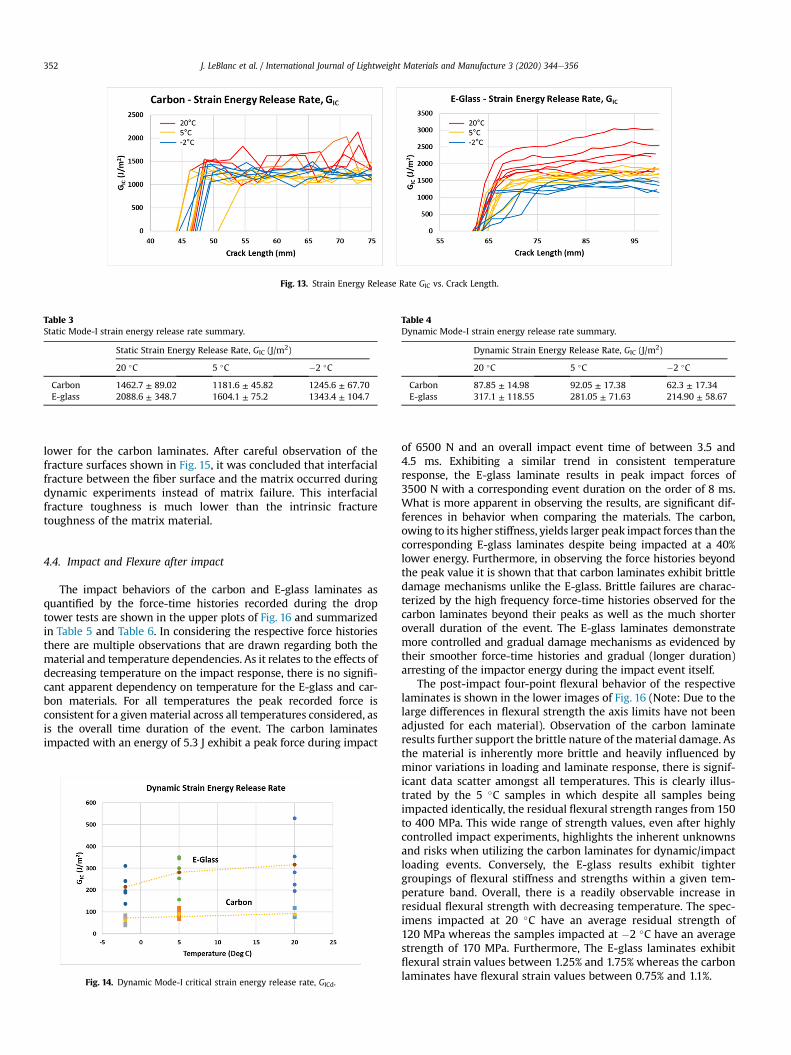
lower for the carbon laminates. After careful observation of thefracture surfaces shown in Fig. 15, it was concluded that interfacialfracture between the fiber surface and the matrix occurred duringdynamic experiments instead of matrix failure. This interfacialfracture toughness is much lower than the intrinsic fracturetoughness of the matrix material.
4.4. Impact and Flexure after impact
The impact behaviors of the carbon and E-glass laminates asquantified by the force-time histories recorded during the droptower tests are shown in the upper plots of Fig. 16 and summarizedin Table 5 and Table 6. In considering the respective force historiesthere are multiple observations that are drawn regarding both thematerial and temperature dependencies. As it relates to the effects ofdecreasing temperature on the impact response, there is no signifi-cant apparent dependency on temperature for the E-glass and car-bon materials. For all temperatures the peak recorded force isconsistent for a given material across all temperatures considered, asis the overall time duration of the event. The carbon laminatesimpacted with an energy of 5.3 J exhibit a peak force during impact
of 6500 N and an overall impact event time of between 3.5 and4.5 ms. Exhibiting a similar trend in consistent temperatureresponse, the E-glass laminate results in peak impact forces of3500 N with a corresponding event duration on the order of 8 ms.What is more apparent in observing the results, are significant dif-ferences in behavior when comparing the materials. The carbon,owing to its higher stiffness, yields larger peak impact forces than thecorresponding E-glass laminates despite being impacted at a 40%lower energy. Furthermore, in observing the force histories beyondthe peak value it is shown that that carbon laminates exhibit brittledamage mechanisms unlike the E-glass. Brittle failures are charac-terized by the high frequency force-time histories observed for thecarbon laminates beyond their peaks as well as the much shorteroverall duration of the event. The E-glass laminates demonstratemore controlled and gradual damage mechanisms as evidenced bytheir smoother force-time histories and gradual (longer duration)arresting of the impactor energy during the impact event itself.
The post-impact four-point flexural behavior of the respectivelaminates is shown in the lower images of Fig. 16 (Note: Due to thelarge differences in flexural strength the axis limits have not beenadjusted for each material). Observation of the carbon laminateresults further support the brittle nature of thematerial damage. Asthe material is inherently more brittle and heavily influenced byminor variations in loading and laminate response, there is signif-icant data scatter amongst all temperatures. This is clearly illus-trated by the 5 �C samples in which despite all samples beingimpacted identically, the residual flexural strength ranges from 150to 400 MPa. This wide range of strength values, even after highlycontrolled impact experiments, highlights the inherent unknownsand risks when utilizing the carbon laminates for dynamic/impactloading events. Conversely, the E-glass results exhibit tightergroupings of flexural stiffness and strengths within a given tem-perature band. Overall, there is a readily observable increase inresidual flexural strength with decreasing temperature. The spec-imens impacted at 20 �C have an average residual strength of120 MPa whereas the samples impacted at �2 �C have an averagestrength of 170 MPa. Furthermore, The E-glass laminates exhibitflexural strain values between 1.25% and 1.75% whereas the carbonlaminates have flexural strain values between 0.75% and 1.1%.
Fig. 13. Strain Energy Release Rate GIC vs. Crack Length.
Table 3Static Mode-I strain energy release rate summary.
Static Strain Energy Release Rate, GIC (J/m2)
20 �C 5 �C �2 �C
Carbon 1462.7 ± 89.02 1181.6 ± 45.82 1245.6 ± 67.70E-glass 2088.6 ± 348.7 1604.1 ± 75.2 1343.4 ± 104.7
Fig. 14. Dynamic Mode-I critical strain energy release rate, GICd.
Table 4Dynamic Mode-I strain energy release rate summary.
Dynamic Strain Energy Release Rate, GIC (J/m2)
20 �C 5 �C �2 �C
Carbon 87.85 ± 14.98 92.05 ± 17.38 62.3 ± 17.34E-glass 317.1 ± 118.55 281.05 ± 71.63 214.90 ± 58.67
J. LeBlanc et al. / International Journal of Lightweight Materials and Manufacture 3 (2020) 344e356352

4.5. Dynamic mechanical analysis
The most significant changes in the mechanical properties ofpolymers take place around Tg where polymer mobility increasesand above which entropic elasticity allows molecules to unravel at
certain time scales. In order to study the viscoelastic properties ofthe FRC at a range of frequencies beyond that range which ispossible with the dynamic mechanical analyzer (TA Q800 DMAmachine), the time-temperature superposition (TTS) techniquewasused to generate curves that capture the major features of the
Fig. 15. Dynamic fracture surfaces for (a) E-glass/epoxy and (b) carbon/epoxy composites.
Fig. 16. Impact and flexure after impact performance.
Table 5Carbon impact and flexure after impact summary.
Carbon
20 �C 5 �C �2 �C
Maximum ImpactForce (N)
6269 ± 157.43 6358 ± 91 6490 ± 145.97
Maximum FlexuralStress (MPa)
277.11 ± 70.81 298.83 ± 103.69 345.02 ± 120.1
Table 6E-glass impact and flexure after impact summary.
E-glass
20 �C 5 �C �2 �C
Maximum ImpactForce (N)
3401 ± 85.83 3608 ± 110.99 3548 ± 93.50
Maximum FlexuralStress (MPa)
116.23 ± 24.96 156.66 ± 7.28 173.19 ± 5.00
J. LeBlanc et al. / International Journal of Lightweight Materials and Manufacture 3 (2020) 344e356 353

polymer's dependence on time and temperature. To perform theTTS analysis a beam for each material specimen was installed intothe 20 mm dual-cantilever clamp and subsequently enclosedwithin the DMA's temperature-controlled oven, which was equili-brated initially to�100 �C and held for a period of 3 min. The clampwas then re-tightened around the specimen, to correct for changesin volume due to thermal stresses, before beginning the first fre-quency sweep. The sample was then held at �100 �C for another2 min. The sample was perturbed with displacements amplitudesof 12 mm (corresponding to 0.07% maximum strain) during thefrequency sweeps. Each frequency sweep consisted of 17 pointswith logarithmic spacing (8 points per decade) from 1 Hz to 100 Hz.Sweeps were performed at 20 �C intervals from �100 �C to 20 �C,
10 �C intervals from 40 �C to 120 �C, and 20 �C intervals from 140 �Cto 180 �C. After equilibrating to the new temperature, the ovenexecuted a 5-min isothermal hold before beginning the frequencysweep. Force, displacement magnitude, and phase angle (d) wererecorded at each frequency point. After the 20 �C equilibration andbefore the subsequent isothermal hold, the clamp was loosenedand re-tightened to prevent thermal expansion from causing highstresses due to clamping. Procedures for DMA of the carbon lami-nates were similar to those of E-glass, although the ordering of thetest frequencies in the sweep was changed from ascending(1e100 Hz) to descending (100e1 Hz).
Temperature dependent behavior of the storage modulus (E’)and loss factor (tan d) at 1 Hz is shown in Fig. 17. The characteristic
Fig. 17. Fiber reinforced composite storage and loss moduli at 1 Hz.
Fig. 18. Storage and loss moduli for E-glass and carbon laminates scaled to 0 �C.
J. LeBlanc et al. / International Journal of Lightweight Materials and Manufacture 3 (2020) 344e356354

glass transition behavior was observed, identified by a significantdecrease in storage modulus and a corresponding peak in visco-elastic dissipation as the temperature passes through the Tg. Bothcarbon and E-glass laminate glass transition temperature wasmeasured at the tan d peak to be approximately 80 �C.
The storage moduli and tan d from individual frequency sweepswere assembled into master curves by adjusting the parameters C1and C2 of a modified version of the Williams, Landel, and Ferry(WLF) equation and assuming bTz1
aT ¼h
h0¼ exp
��C1ðT � T0ÞC2 þ T � T∞
�(9)
to achieve continuity in scaled frequency aTu. The values of C1 andC2 that best fit this criterion were approximately 70 and 180 K,respectively for the E-glass laminate. The Carbon laminate was bestfit with values of 80 K and 190 K for C1 and C2, respectively. T∞ was278 K for both laminate types.
Expressing these curves in terms of their corresponding realfrequencies, in Hertz and at a temperature of 0 �C, merely requiresremoval of the scaling term aT as it evaluates at that temperature.Themaster curves for themoduli of E-glass and carbon laminates ata reference temperature of 0 �C are shown in Fig. 18. They revealthat there is little reason to expect polymer-related losses in ma-terial transmission frequencies at Arctic temperatures since thetan d values are less than 0.1 above frequencies on the order of10�3 Hz (Fig. 19). The mechanical properties of fiber-reinforcedepoxy composites are essentially constant within the frequencyranges of interest in acoustics. This is perhaps unsurprising giventhe high Tg of most epoxies.
5. Conclusions
A detailed experimental investigation of the effects of lowtemperature on the mechanical, fracture, and frequency dependentmaterial properties of E-glass/epoxy and carbon/epoxy laminateshas been conducted. The investigation was primarily aimed atestablishing a foundational understanding of the temperature
effects on composite laminates at temperatures of interest to themarine community. Historically, mechanical and acoustic proper-ties at operating temperatures in the range of 15 �Ce20 �C havebeen evaluated, with minimal data pertaining to the temperaturesassociated with Arctic seawater in the 2 �Ce4 �C regime. The keyfindings of the study were as follows:
5.1. Mechanical performance
(1) Tension: The specific E-glass/epoxy material investigatedexhibited a minimal dependence on decreasing temperaturein terms of elastic modulus and tensile strength. There is ameasurable dependence on decreasing temperature for thecarbon/epoxy laminate evaluated with the material bothstiffening and strengthening over the range 20 �C to �2 �C.Specifically, an 11% increase in modulus and a 7% increase instrength with decreasing temperature. Hence an inverserelationship between tensile performance and temperature.
(2) Compression: The specific E-glass/epoxy material utilized inthis study exhibited opposite trends in stiffness and strengthwith decreasing temperature. As the temperature isdecreased the material became softer but stronger. Carbon/epoxy laminates exhibited decreasing stiffness withdecreasing temperature, a decrease of 30% over the rangeconsidered, and a material strength decrease from 20 �C to5 �C followed by near constant strength from 5 �C to �2 �C.
(3) Short Beam Shear: The E-glass/epoxy laminates were charac-terized by a flat plateau in stress with increasing displacementafter reaching maximum load whereas the carbon laminatesexhibit decreasing stress capacity after maximum load. Thecarbon and E-glass laminates exhibited a 20% increase in shortbeam shear strength over the range from 20 �C to �2 �C.
5.2. Fracture performance
(1) Static Mode-I: Both of the E-glass and carbon laminatesconsidered, exhibited a direct dependence of GIC on
Fig. 19. Storage and loss moduli for E-glass and carbon laminates at relevant frequencies for physical processes.
J. LeBlanc et al. / International Journal of Lightweight Materials and Manufacture 3 (2020) 344e356 355
temperature with an observable trend that with decreasingtemperature there was a corresponding decrease in GIC. TheE-glass laminates had a GIC value of 1400 J/m2 at�2 �C, whichwas 65% of the corresponding value at 20 �C, 2100 J/m2.
(2) Dynamic Mode-I: The E-glass laminates exhibited highercritical strain energy release rates than the carbon laminatesfor dynamic Mode-I fracture. Additionally, the E-glass lami-nates displayed a larger dependence on temperature thandid the carbon laminates. Finally, the observed dynamicMode-I GICd values are significantly lower than the staticMode-I values.
5.3. Impact and flexure after impact strength performance
(1) Impact: The E-glass and carbon laminates show no signifi-cant dependence on impact behavior as a function of tem-perature in that the peak impact force is consistent across thetemperature range considered in the study. However, thecarbon laminates exhibit a brittle type behavior underimpact loading whereas the E-glass laminates are morecompliant during loading event.
(2) Flexure after impact: The four-point flexure after impactbehavior of the E-glass laminate evaluated in the currentstudy exhibits a trend in which the flexural strength de-creases with increasing temperature with the specimensimpacted at �2 �C having a larger residual strength than thesamples impacted at 20 �C. There was no discernible trendfound in the carbon laminates as the brittleness of the ma-terial under impact loading resulted in significant scatter inthe results, even while the impact energy was consistent inall samples.
5.4. Dynamic Mechanical Analysis (DMA)
The linear viscoelastic behavior at small strains exhibit a matrixdominant behavior with a composite behavior at higher strain ratesemerging for the carbon laminates at a lower strain level than forthe E-glass laminates. The glass transition temperatures for the E-glass and carbon laminates are approximately 72 �C and 80 �Crespectively. The mechanical properties of fiber-reinforced epoxycomposites are essentially constant within the frequency ranges ofinterest in underwater acoustics.
The primary objective of the current manuscript was to presentthe meaningful findings pertaining to the mechanical and fre-quency dependent properties of carbon and E-glass laminates attemperatures of interest to the marine industry, specifically
submerged vehicles. To further expand this breadth of knowledge,additional studies are warranted for low temperatures corre-sponding to structures exposed to low temperature air where thetemperatures can be significantly lower than those of seawater.
Conflicts of interest
The authors declare that there is no conflicts of interest.
Acknowledgements
The financial support of the Naval Undersea Warfare Center(Division Newport) Internal Investment Program and In-HouseLaboratory Independent Research (ILIR) programs are gratefullyacknowledged.
References
[1] D. Li, D. Fang, G. Zhang, H. Hu, Effect of temperature on bending propertiesand failure mechanism of three-dimensional braided composite, Mater. Des.41 (2012) 167e170.
[2] S. Kichhannagari, Effects of Extreme Low Temperature on Composite Mate-rials, University of New Orleans Theses and Dissertations, 2004. Paper 165.
[3] G. Springer, Environmental Effects on Composite Materials, Technomic Pub-lishing Co, Inc., 1981.
[4] R.M. Jones, Mechanics of Composite Materials, Hemisphere Publishing Corp.,1975.
[5] J.C. Halpin, Primer on Composite Materials: Analysis, Technomic PublishingCo, Inc., 1984.
[6] V. Lopresto, I. Papa, A. Langella, Residual strength evaluation after impact testsin extreme temperature conditions. New equipment for CAI tests, CompositesPart B 127 (2017) 44e52.
[7] I. Papa, A. Langella, V. Lopresto, Dynamic performances of basalt fibre lami-nates at room and low temperatures, Compos. Struct. 220 (2019) 652e661.
[8] Technical Reference Handbook, JPS Composite Materials, Anderson, SC.https://jpscm.com/wp-content/uploads/2017/10/2017-Data-Book-Small-1.pdf.
[9] ASTM D638-14, Standard Test Method for Tensile Properties of Plastics, ASTMInternational, West Conshohocken, PA, 2014. www.astm.org.
[10] ASTM D3410/D3410M-16, Standard Test Method for Compressive Propertiesof Polymer Matrix Composite Materials with Unsupported Gage Section byShear Loading, ASTM International, West Conshohocken, PA, 2016. www.astm.org.
[11] ASTM D2344/D2344M-16, Standard Test Method for Short-Beam Strength ofPolymer Matrix Composite Materials and Their Laminates, ASTM Interna-tional, West Conshohocken, PA, 2016. www.astm.org.
[12] P. Cavallaro, Effects of weave styles and crimp gradients in woven kevlar/epoxy composites, Exp. Mech. 56 (2016) 617e635.
[13] ASTM D5528-13, Standard Test Method for Mode I Interlaminar FractureToughness of Unidirectional Fiber-Reinforced Polymer Matrix Composites,ASTM International, West Conshohocken, PA, 2013.
[14] T. Kusaka, M. Hojo, Y. Mai, T. Kurokawa, T. Nojima, S. Ochiai, Rate dependanceof mode I fracture behavior in carbon-fibre/epoxy composite laminates,Compos. Sci. Technol. 58 (1998) 591e602.
[15] M. Rubinstein, R.H. Colby, Polymer Physics, Oxford University, Oxford, 2003.
J. LeBlanc et al. / International Journal of Lightweight Materials and Manufacture 3 (2020) 344e356356