low-speed aerodynamic characteristics of a lifting … · stability characteristics of a...
TRANSCRIPT

AND
16^
NASA TECHNICAL NOTE NASA TN D-7851
I-
/ (NASA-TN-D-7851) LOW SPEED AERODYNAMIC N75-1561
ICHARACTERISTICS OF A LIFTING-BODY HYPERSONICRESEARCH AIRCRAFT CONFIGURATION (NASA) 69 pHC $4.25 CSCL 01C Unclas
_ H 1 02 09056
LOW-SPEED AERODYNAMIC CHARACTERISTICS
OF A LIFTING-BODY HYPERSONIC RESEARCH
AIRCRAFT CONFIGURATION ,
Jim A. Penland and Theodore R. Creel, Jr. 1' < - -
Langley Research Center
Hampton, Va. 23665 , A'76 .R191
NATIONAL AERONAUTICS AND SPACE ADMINISTRATION • WASHINGTON, D. C. • FEBRUARY 1975
https://ntrs.nasa.gov/search.jsp?R=19750007539 2020-01-08T07:44:30+00:00Z
1. Report No. 2. Government Accession No. 3. Recipient's Catalog No.
NASA TN D-78514. Title and Subtitle 5. Report Date
LOW-SPEED AERODYNAMIC CHARACTERISTICS OF A February 1975
LIFTING-BODY HYPERSONIC RESEARCH AIRCRAFT 6. Performing Organization Code
CONFIGURATION7. Author(s) 8. Performing Organization Report No.
Jim A. Penland and Theodore R. Creel, Jr. L-9811
10. Work Unit No.
9. Performing Organization Name and Address 505-11-31-02
NASA Langley Research Center 11. Contract or Grant No.
Hampton, Va. 23665
13. Type of Report and Period Covered
12. Sponsoring Agency Name and Address Technical NoteNational Aeronautics and Space Administration 14. Sponsoring Agency CodeWashington, D.C. 20546
15. Supplementary Notes
16. Abstract
An experimental investigation of the low-speed longitudinal, lateral, and directional
stability characteristics of a lifting-body hypersonic research airplane concept was con-
ducted in a low-speed tunnel with a 12-foot (3.66-meter) octagonal test section at the
Langley Research Center. The model was tested with two sets of horizontal and vertical
tip controls having different planform areas, a center vertical tail and two sets of canard
controls having trapezoidal and delta planforms, and retracted and deployed engine modules
and canopy. This investigation was conducted at a dynamic pressure of 239.4 Pa (5 psf)
(Mach number of 0.06) and a Reynolds number of 2 x 10⁶ based on the fuselage length.
The tests were conducted through an angle-of-attack range of 00 to 300 and through
horizontal-tail deflections of 100 to -300.
The complete configuration exhibited excessive positive static longitudinal stability
about the design center-of-gravity location. However, the configuration was unstable lat-
erally at low angles of attack and unstable directionally throughout the angle-of-attack
range. Longitudinal control was insufficient to trim at usable angles of attack. Experi-
ments showed that a rearward shift of the center of gravity and the use of a center-located
vertical tail would result in a stable and controllable vehicle.
17. Key Words (Suggested by Author(s)) 18. Distribution Statement
Hypersonic aircraft Unclassified - Unlimited
Low-speed stability and control
Lifting body
Aerodynamics STAR Category 02
19. Security Classif. (of this report) 20. Security Classif. (of this page) 21. No. of Pages 22. Price*
Unclassified Unclassified 69 $4.25
For sale by the National Technical Information Service, Springfield, Virginia 22151

LOW-SPEED AERODYNAMIC CHARACTERISTICS OF A LIFTING-BODY
HYPERSONIC RESEARCH AIRCRAFT CONFIGURATION
By Jim A. Penland and Theodore R. Creel, Jr.
Langley Research Center
SUMMARY
An experimental investigation of the low-speed longitudinal, lateral, and directional
stability characteristics of a lifting-body hypersonic research airplane concept was con-
ducted in a low-speed tunnel with a 12-foot (3.66-meter) octagonal test section at the
Langley Research Center. The model was tested with two sets of horizontal and vertical
tip controls having different planform areas, a center vertical tail and two sets of canard
controls having trapezoidal and delta planforms, and retracted and deployed engine mod-
ules and canopy. This investigation was conducted at a dynamic pressure of 239.4 Pa
(5 psf) (Mach number of 0.06) and a Reynolds number of 2 x 10⁶ based on the fuselage
length. The tests were conducted through an angle-of-attack range of 00 to 300 and
through horizontal-tail deflections of 100 to -300.
The complete configuration exhibited excessive positive static longitudinal stability
about the design center-of-gravity location. However, the configuration was unstable
laterally at low angles of attack and unstable directionally throughout the angle-of-attack
range. Longitudinal control was insufficient to trim at usable angles of attack. Experi-
ments showed that a rearward shift of the center of gravity and the use of a center-located
vertical tail would result in a stable and controllable vehicle.
INTRODUCTION
Under a National Aeronautics and Space Administration contract (refs. 1 to 4),
McDonnell Aircraft Company identified the required research for future hypersonic cruise
aircraft, evaluated the research potential, and assessed the usefulness of several new
candidate research facilities. This Hypersonic Research Facilities (HYFAC) study con-
cluded that major advances must be made in the technological state of the art before air-
breathing hypersonic aircraft employing advanced propulsion and fuel systems could be
considered either feasible or practical. Recommendations were made that both ground
facilities and flight vehicles be utilized in order to improve the state of the art aerody-
namically, structurally, and propulsively.
One recommended flight research aircraft, a model of which is shown in figures 1
and 2, was a manned Mach 12, air-launched, rocket-boosted, all-body aerothermodyriamic
configuration that would operate in the true high-temperature environment. After boost,this test aircraft would cruise at a constant Mach number for up to 5 minutes, and record
data throughout the flight mission. The aircraft would then decelerate to a dead-stick
landing as has been customary for previous research aircraft. Reference 5 reported
the aerodynamic characteristics of this all-body hypersonic research aircraft configura-
tion at Mach 6. References 6 and 7 documented the aerodynamic characteristics of sim-
ilar configurations at low speeds.
Because the proposed research aircraft will be flown to a powerless landing, the
low-speed aerodynamic characteristics must be known. The purpose of this report is to
document the aerodynamic characteristics of a lifting-body hypersonic research airplane
at a dynamic pressure of 239.4 Pa (5 psf) (Mach number of 0.06) and a Reynolds number
of 2 x 10⁶ based on the fuselage length.
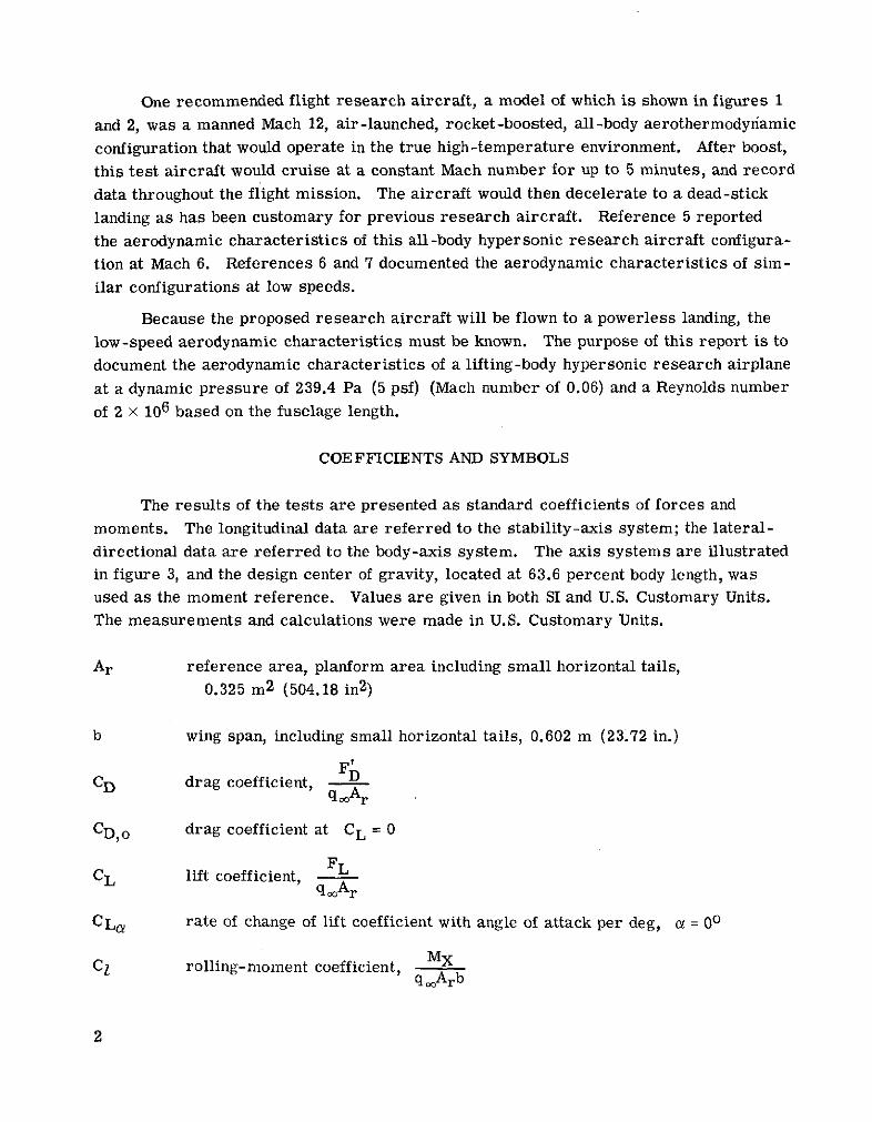
COEFFICIENTS AND SYMBOLS
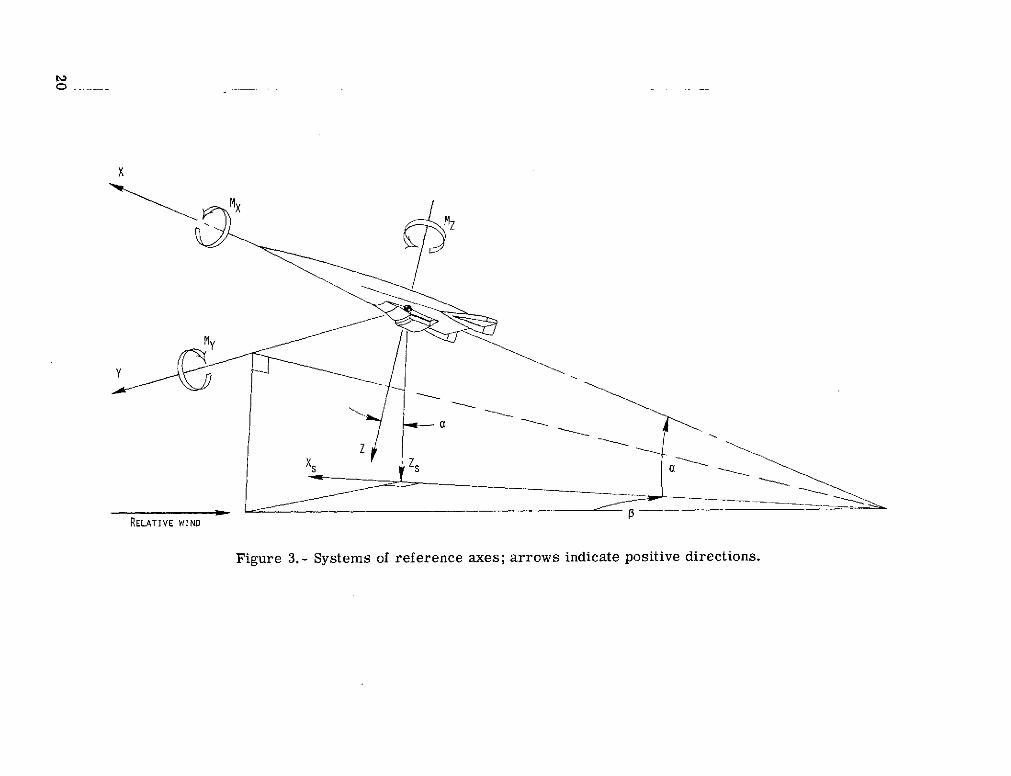
The results of the tests are presented as standard coefficients of forces and
moments. The longitudinal data are referred to the stability-axis system; the lateral-
directional data are referred to the body-axis system. The axis systems are illustrated
in figure 3, and the design center of gravity, located at 63.6 percent body length, wasused as the moment reference. Values are given in both SI and U.S. Customary Units.
The measurements and calculations were made in U.S. Customary Units.
Ar reference area, planform area including small horizontal tails,0.325 m2 (504.18 in 2)
b wing span, including small horizontal tails, 0.602 m (23.72 in.)
FDICD drag coefficient, DC ooAr
CD, o drag coefficient at CL = 0
CL lift coefficient,qoAr
CLa rate of change of lift coefficient with angle of attack per deg, c = 00
MXC1 rolling-moment coefficient, MX
ooArb
2

C10 rate of change of rolling-moment coefficient with angle of sideslip per deg
MyCm pitching-moment coefficient, qMArl
Cm, rate of change of pitching-moment coefficient with angle of attack per deg,
a = 00
Cm,o pitching-moment coefficient at a = 00
8 Cm rate of change of pitching-moment coefficient with lift coefficient,aC L longitudinal stability
M ZCn yawing-moment coefficient, MzArb
Cn rate of change of yawing-moment coefficient with angle of sideslip per deg
Cy side-force coefficient,qAoor
Cyp rate of change of side-force coefficient with angle of sideslip per deg
c wing chord
cr,exp exposed root chord
FA axial force along X-axis; positive direction, -X
Fb = FN sin a + FA cos a
FL = FN cos a - FA sin a
FN normal force along Z-axis; positive direction, -Z
Fy side force along Y-axis; positive direction, +Y
L/D lift-drag ratio, CD
reference length (length of sharp nosed body), 1.528 m (60.15 in.)
M Mach number
3

MX, My, MZ moments about X-, Y-, and Z-axes
gq free-stream dynamic pressure
X,Y,Z reference axes
x distance, theoretical nose to body station
z distance vertical from horizontal center line
a angle of attack, deg
P angle of sideslip, deg
6 angle of control deflection, positive deflection when trailing edge is down, deg
Subscripts:
C both canards deflected
H both elevons deflected
s stability-axis system
t trim condition, Cm = 0
Model nomenclature:
B body or fuselage
C 1 small trapezoidal canards
C 2 small delta-planform canards
C3 large trapezoidal canards
C 4 large delta-planform canards
Cp deployed canopy
4
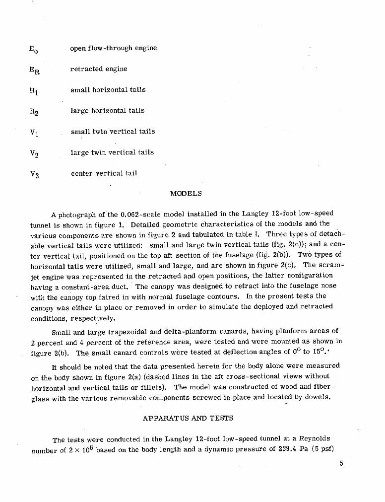
E o open flow-through engine
ER retracted engine
H1 small horizontal tails
H2 large horizontal tails
V1 small twin vertical tails
V2 large twin vertical tails
V3 center vertical tail
MODELS
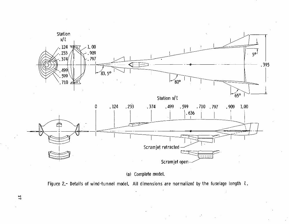
A photograph of the 0.062-scale model installed in the Langley 12-foot low-speed
tunnel is shown in figure 1. Detailed geometric characteristics of the models and the
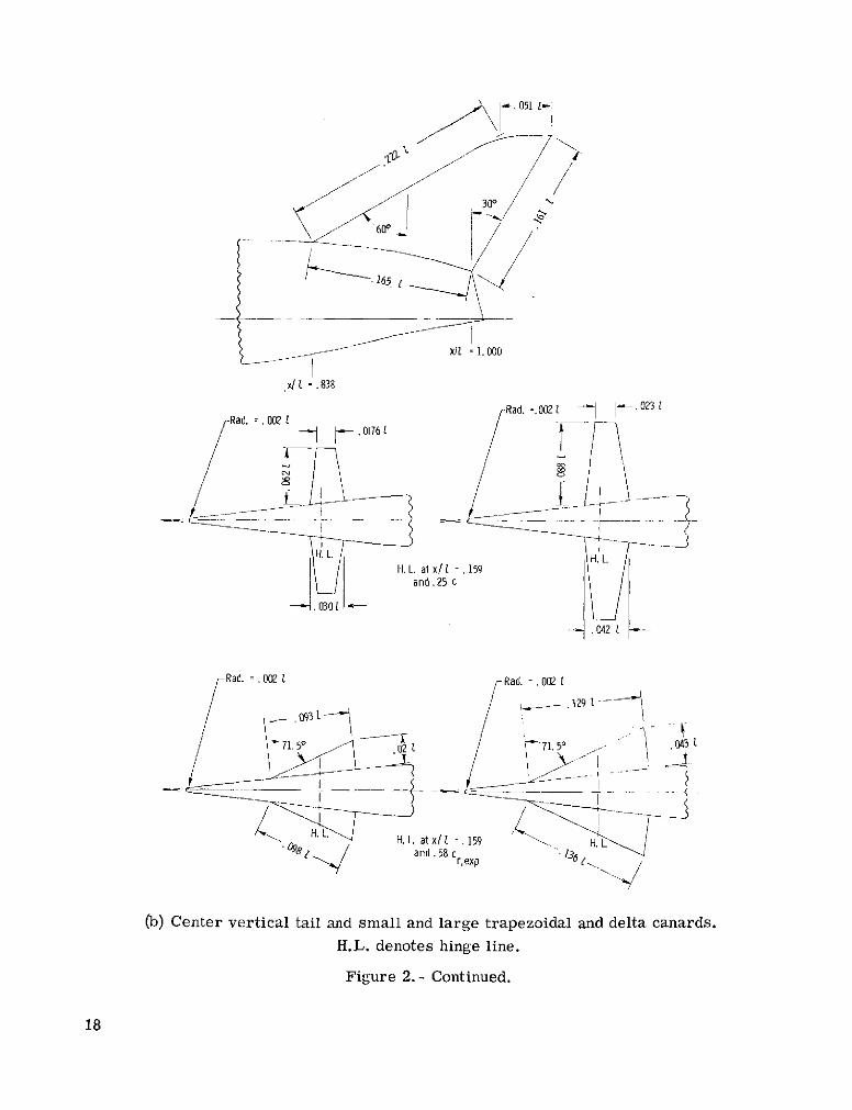
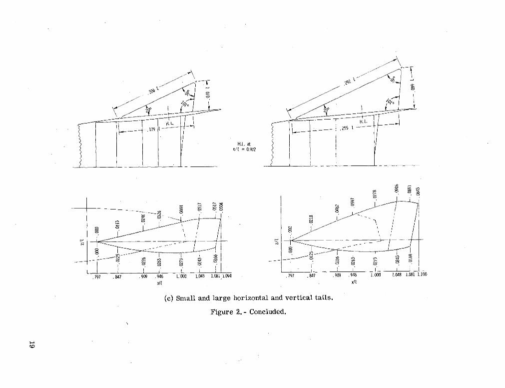
various components are shown in figure 2 and tabulated in table I. Three types of detach-
able vertical tails were utilized: small and large twin vertical tails (fig. 2(c)); and a cen-
ter vertical tail, positioned on the top aft section of the fuselage (fig. 2(b)). Two types of
horizontal tails were utilized, small and large, and are shown in figure 2(c). The scram-
jet engine was represented in the retracted and open positions, the latter configuration
having a constant-area duct. The canopy was designed to retract into the fuselage nose
with the canopy top faired in with normal fuselage contours. In the present tests the
canopy was either in place or removed in order to simulate the deployed and retracted
conditions, respectively.
Small and large trapezoidal and delta-planform canards, having planform areas of
2 percent and 4 percent of the reference area, were tested and were mounted as shown in
figure 2(b). The small canard controls were tested at deflection angles of 00 to 150.1
It should be noted that the data presented herein for the body alone were measured
on the body shown in figure 2(a) (dashed lines in the aft cross-sectional views without
horizontal and vertical tails or fillets). The model was constructed of wood and fiber-
glass with the various removable components screwed in place and located by dowels.
APPARATUS AND TESTS
The tests were conducted in the Langley 12-foot low-speed tunnel at a Reynolds
number of 2 x 10⁶ based on the body length and a dynamic pressure of 239.4 Pa (5 psf)
5

(M = 0.06). A six-component strain-gage balance was installed inside the model fuselageand attached to the tunnel sting-support system. The force and moment data were meas-ured through an angle-of-attack range of 00 to 300 and at angles of sideslip of 00, 50,and 100. All joints and hinge-line cracks were sealed with plastic tape prior to each testrun. Brief tests with and without fixed transition indicated no parameter variations otherthan a fractional percent decrease in drag. Therefore, the tests were made without fixedtransition. No base-pressure corrections were made. Moments were calculated abouta center of gravity located on the vehicle center line at the x/l = 0.636 body stationmeasured from the theoretical sharp nose.
Because of the very low test Reynolds number of this investigation and the relativelyhigh turbulence factor of the tunnel flow, it is not recommended that the drag data beextrapolated to flight Reynolds numbers. Lift-curve slopes, moments, and drag incre-ments caused by component variations, however, are considered to be valid.
RESULTS AND DISCUSSION
Static Longitudinal Characteristics
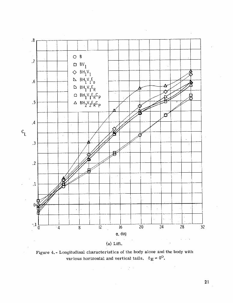
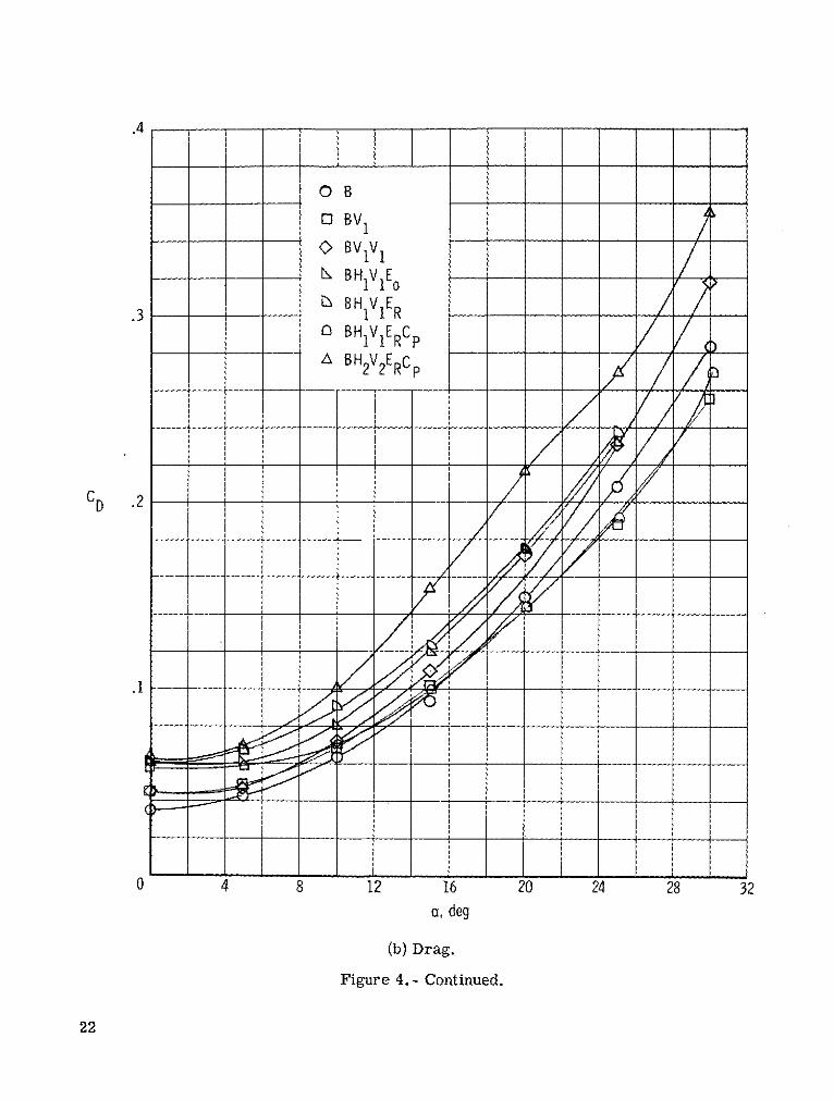
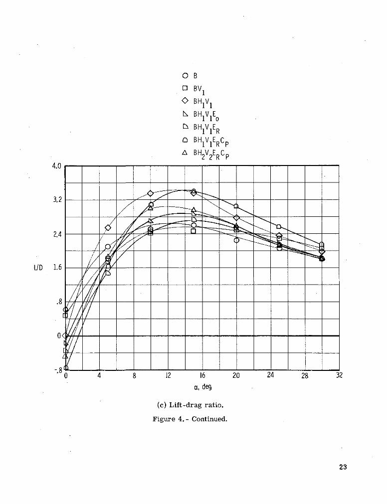
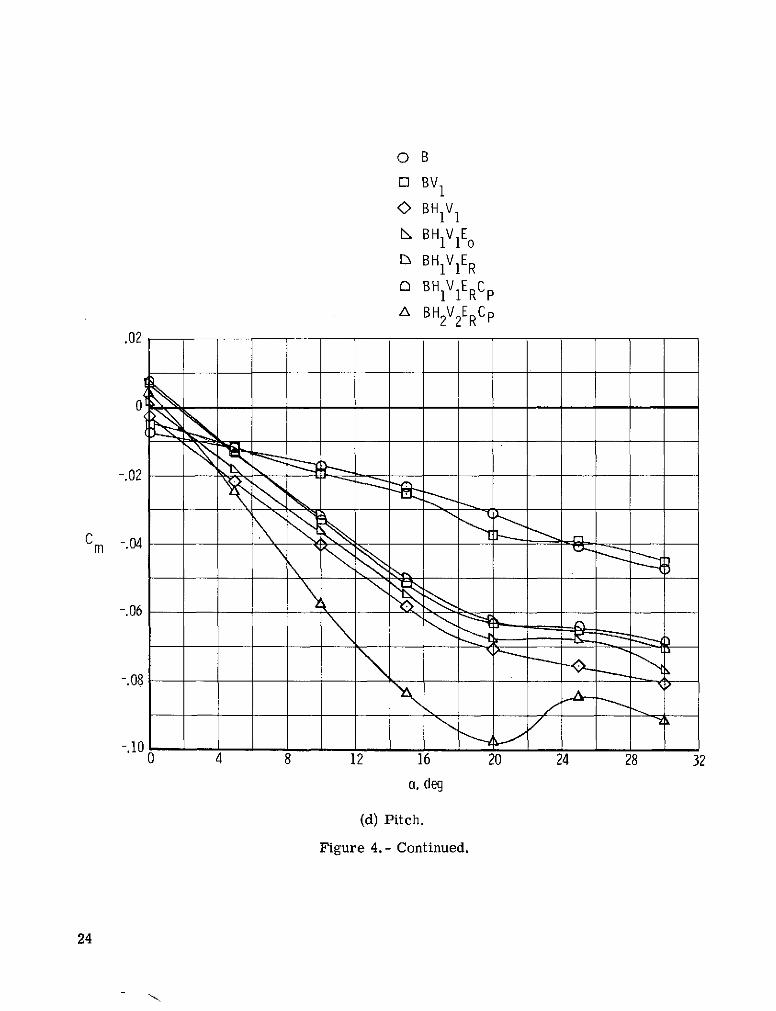
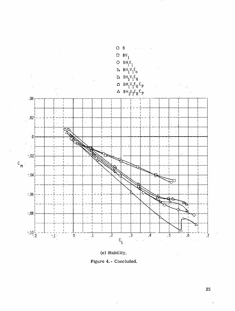
Configuration buildup.- The static longitudinal characteristics of the basic bodyalone and the variations effected by the addition of vertical and horizontal tails, enginemodules, and cockpit are presented in figure 4 through the test range of angles of attackfrom 00 to 300. The body alone (B) and the models with the body and small twin verti-cal tails (BV 1 ) exhibit nonlinear lift curves throughout the test range (fig. 4(a)) as com-pared with the models having horizontal tails (H1 or H2 ), engine modules (E o or ER),and deployed canopy (Cp). These models having horizontal tails, engine modules, anddeployed canopy not only have greater lift but also have linear lift curves up to the regionof probable flow separation on the horizontal tails at an angle of attack of about 200.Conversely, the B and BV 1 models have more linear pitching-moment and stability curves(figs. 4(d) and 4(e)) than do the models with the added components; the models with theadded components not only show a higher degree of stability up to ! = 200 but also havea slight pitch-up tendency. The addition of Eo, ER, or Cp to the BH 1V 1 model shifted theangle of attack for CL = 0 and for Cm = 0 but had no significant effect on the slopesCLa, Cma, and aCm/aCL. The exchange of H2 V2 for H 1 V 1 resulted in a markedimprovement in the aforementioned stability derivatives approximately proportional tothe planform areas involved. This improvement with the use of H2V2 was about 1.5 timesthe gain resulting from the use of H1 V 1 on model B, that is, the ratio of the areas of H2V 2to H1 V 1 . With the exception of the BH1V1ERCP test, the drag and lift-drag ratio resultsof the configuration buildup were as expected: an improvement in L/D with the additionof H1 and a decrease with the addition of Eo, ER, and/or Cp.
6

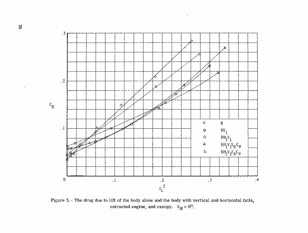
Drag due to lift.- The drag due to lift for most of the configurations just discussed
is presented in figure 5. Again the B and BV 1 models exhibit the most linear of the
curves shown. It should be observed that although model B had the lowest CD,o (drag
at CL = 0), it also had the highest slope aCD/aCL 2 (drag-rise factor) and, therefore,
the greater drag due to lift. The addition of V1 slightly increased CD,o but decreased
the drag-rise factor; this was possibly caused by the end-plate effects of the outboard-
located vertical tails. The addition of H 1 appears to have had a negligible effect on CD,o
but greatly decreased the drag-rise factor and had.a nonlinearizing effect on the curve.
The CD,o was significantly increased by the addition of ER and Cp, but, at the higher
values of CL 2 , the curve is generally similar to that shown for the BH 1V 1 model. The
addition of the larger H2 and V2 again increased the CD,o and further decreased the
drag-rise factor as expected.
Center vertical tail.- Tests using a center vertical tail were conducted primarily
to compare the directional-stability characteristics with those of the twin outboard tails;
these characteristics are discussed in the section entitled "Static Lateral-Directional
Characteristics." However, such tests automatically produce longitudinal data. (See
fig. 6.) The addition of V3 to the basic BH1V1ERCp model resulted in a decrease in CL
and L/D, an increase in CD, a small positive increment of pitching moment, and no
change in Cma, or in the longitudinal stability aCm/aCL. Tests with a.C 1 canard in
conjunction with V3 were made to determine whether any interference could be caused
by the wake or vorticular flow impinging on'the center vertical tail. The use of the small
trapezoidal canards (C1) longitudinally resulted in a small increase in CL approximately
equal to the loss incurred by the use of V3 , a further increase in drag; no change in L/D,
and an additional positive increment in pitching moment with only a negligible change in
Cm, and aCm/aCL.
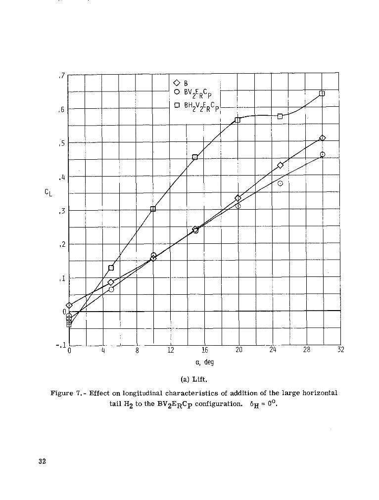
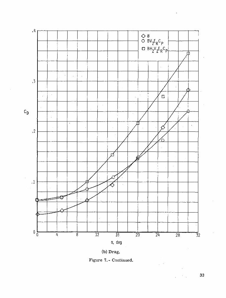
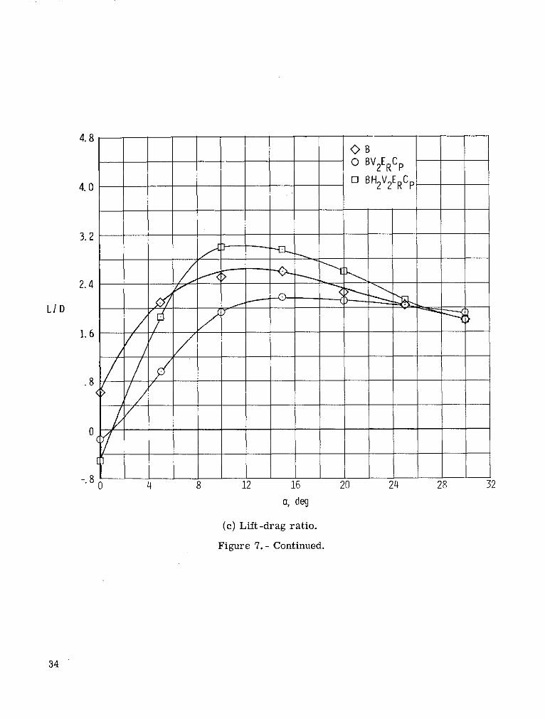
Large vertical and horizontal tails.- Figure 7 presents a partial configuration
buildup utilizing available data on the large vertical and horizontal tails. The most nota-
ble effect of the addition of V2ERCP to the body alone (B) was the reversal of the curva-
ture of the lift, pitch, and stability curves. (See figs. 7(a), 7(d), and 7(e).) The installa-
tion of H2 greatly increased the lift-curve slope CL, and increased negatively the slope
of the pitching-moment curve Cma in the angle-of-attack range up to about 200. There
was little change in the stability aCm/8CL at low lift coefficients corresponding to
a = 00 to 50, but the curve was made almost linear, a condition which extended the region
of positive longitudinal stability to a lift coefficient of about 0.56, corresponding to
a = 200.
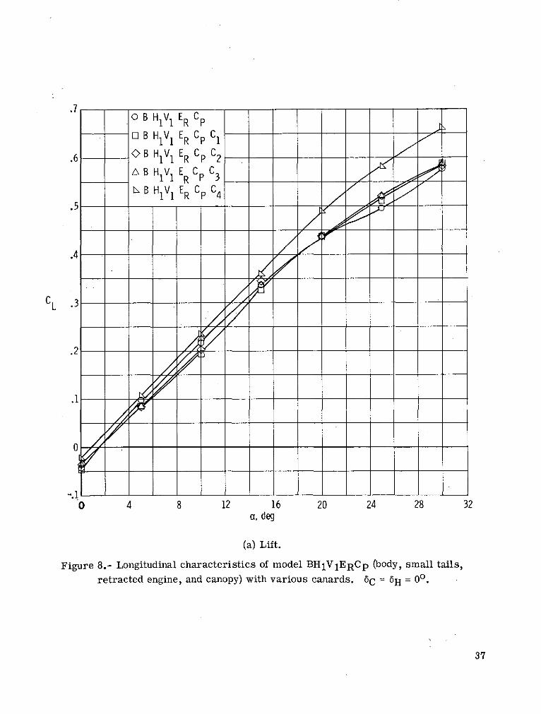
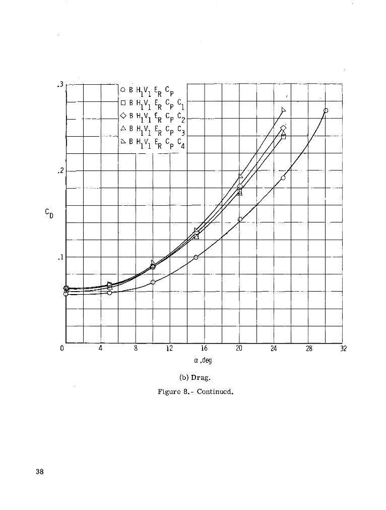
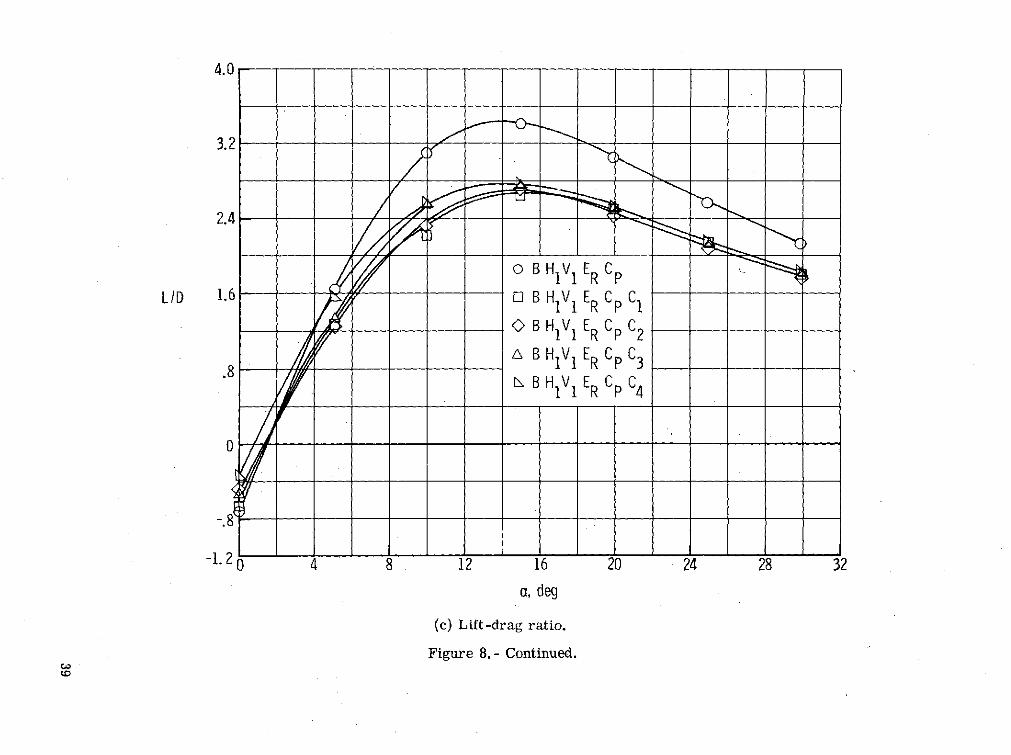
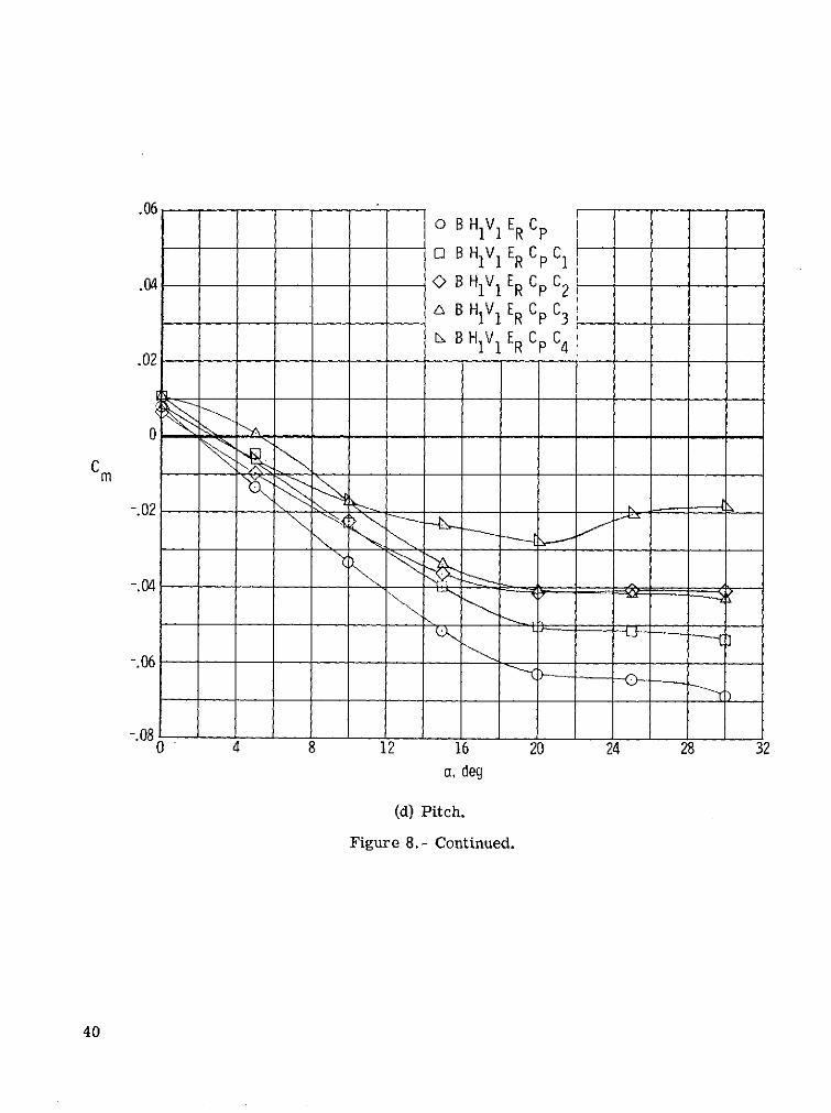
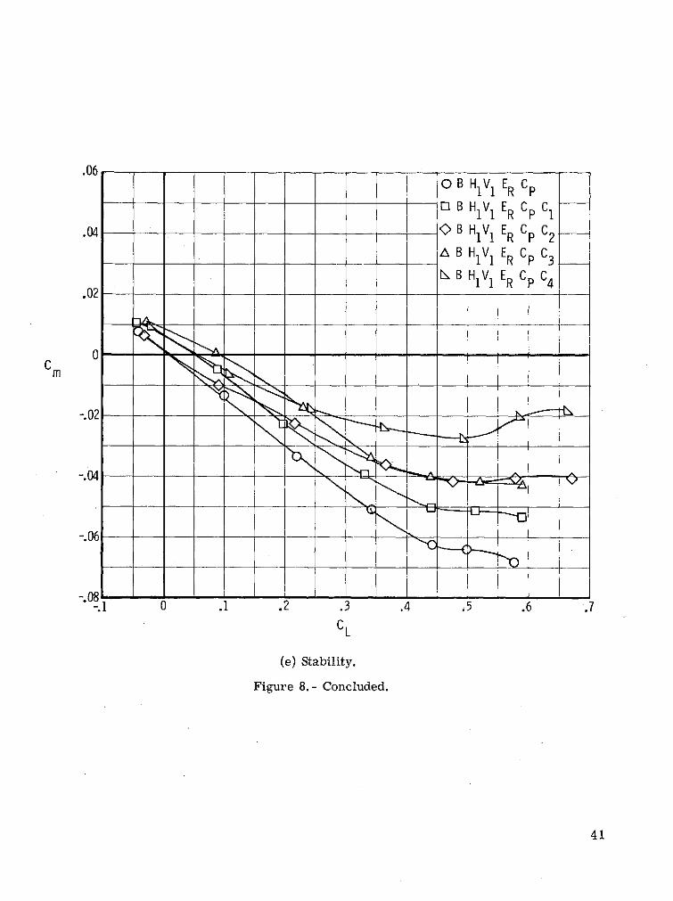
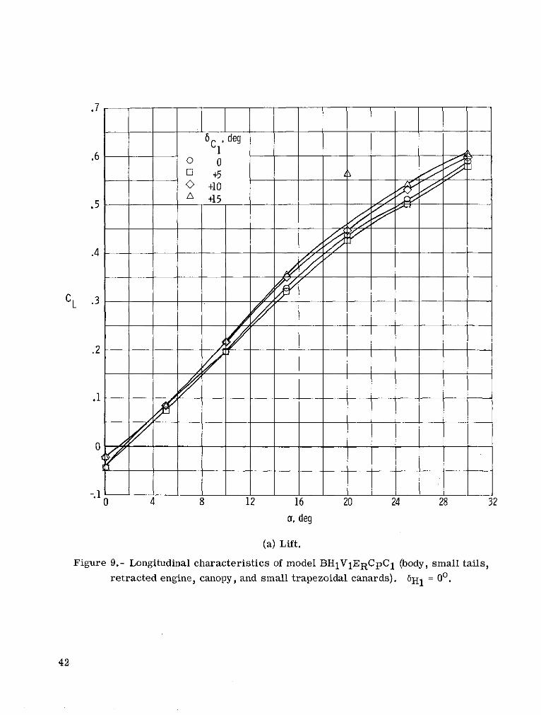
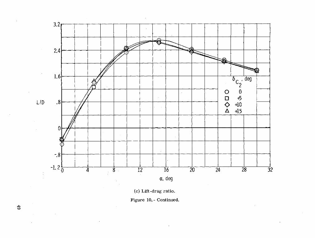
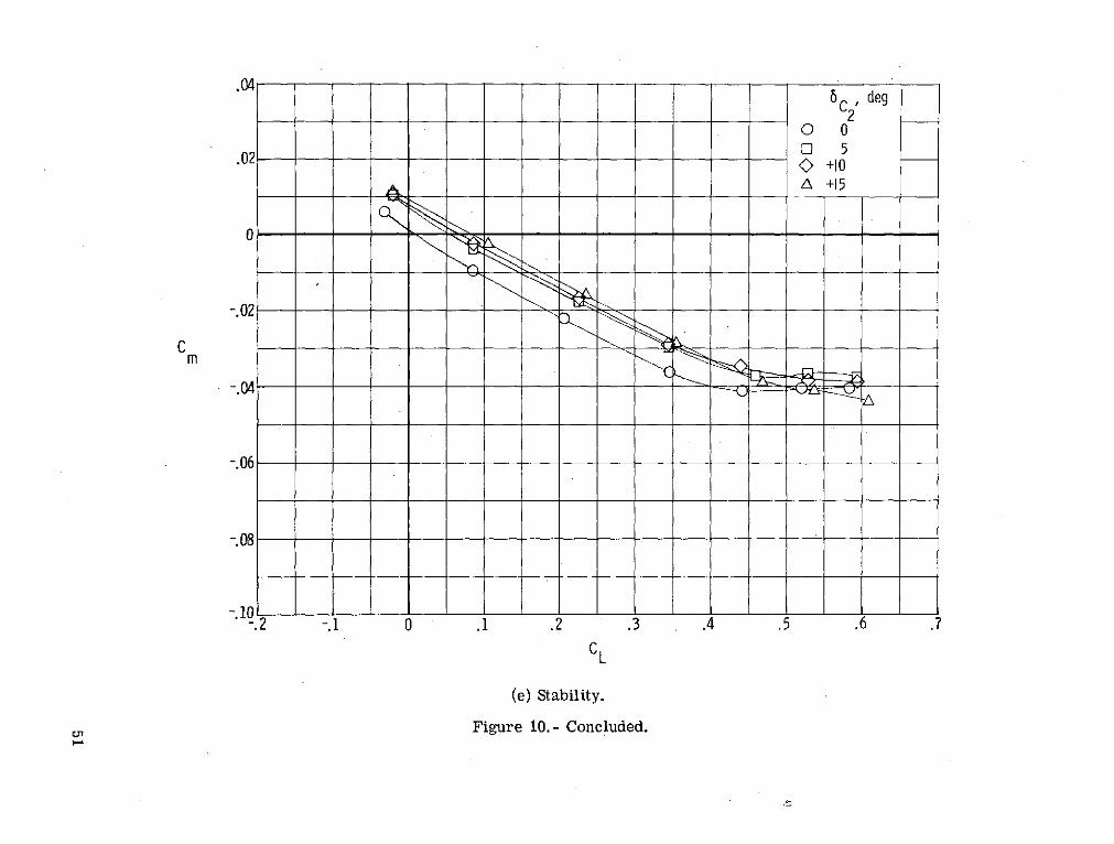
Canards. - The results of the longitudinal tests on the four canard shapes, described
in the section "Models," are presented in figures 8, 9, and 10. Figure 8 presents the
results for the basic complete model BH1V1ERCp and for this model equipped with each
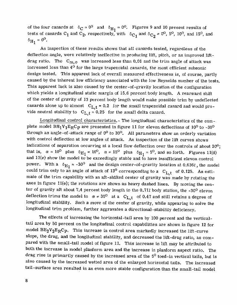
of the four canards at 6C = 00 and 6 H 1 = 00. Figures 9 and 10 present results of
tests of canards C 1 and C 2 , respectively, with 6C1 and 5C2 = 00, 50, 100, and 150, and
H1 = 00.
An inspection of these results shows that all canards tested, regardless of the
deflection angle, were relatively ineffective in producing lift, pitch, or an improved lift-
drag ratio. The Cm,o was increased less than 0.01 and the trim angle of attack was
increased less than 40 for the large trapezoidal canards, the most efficient subsonic
design tested. This apparent lack of overall measured effectiveness is, of course, partly
caused by the inherent low efficiency associated with the low Reynolds number of the tests.This apparent lack is also caused by the center-of-gravity location of the configuration
which yields a longitudinal static margin of 15.6 percent body length. A rearward shiftof the center of gravity of 13 percent body length would make possible trim by undeflectedcanards alone up to almost CL,t = 0.2 for the small trapezoidal canard and would pro-vide neutral stability to CL,t = 0.25 for the small delta canard.
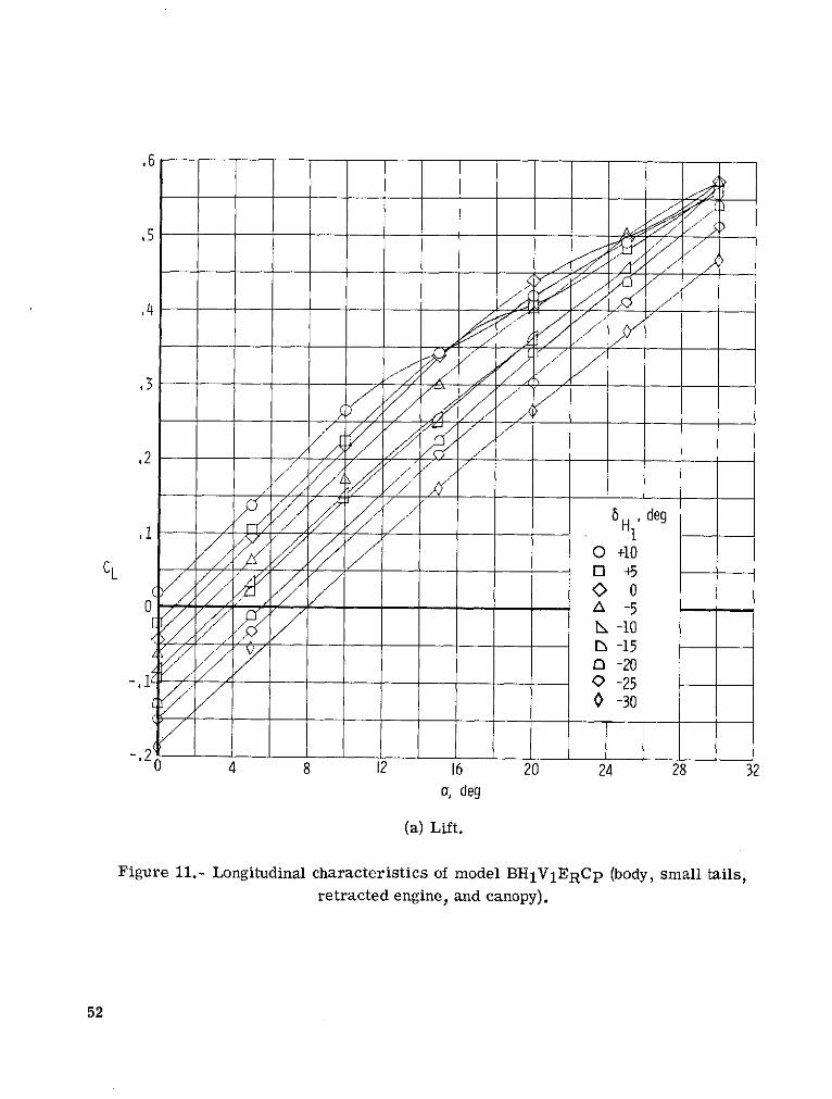
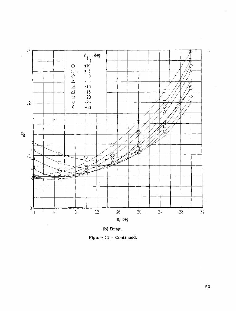
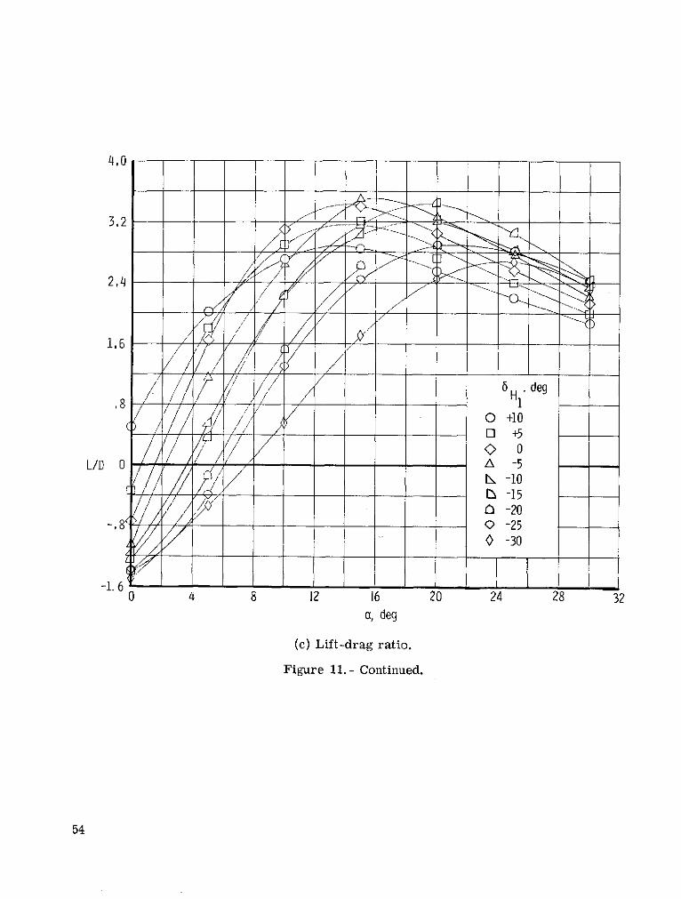
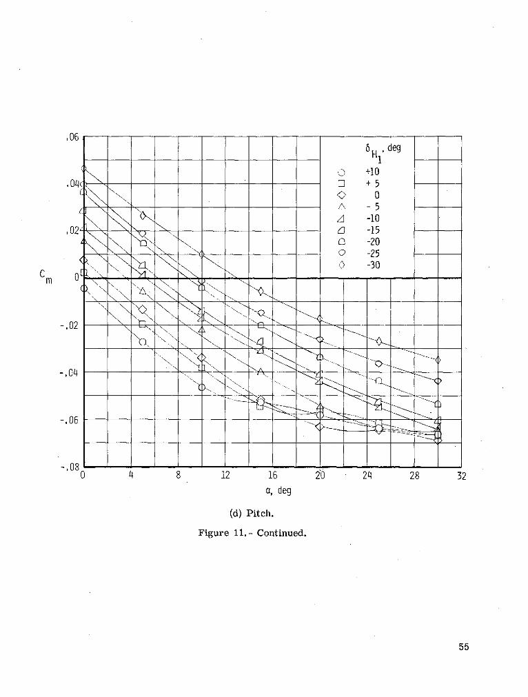
Longitudinal control characteristics.- The longitudinal characteristics of the com-plete model BHlVlERCp are presented in figure 11 for elevon deflections of 100 to -300through an angle-of-attack range of 00 to 30 0 . All parameters show an orderly variationwith control deflection at low angles of attack. An inspection of the lift curves showsindications of separation occurring at a local flow deflection over the controls of about 200;that is, a = 100 plus 6H1 = 100, a = 150 plus 6 H 1 = 50, and so forth. Figures 11(d)and 11(e) show the model to be exceedingly stable and to have insufficient elevon controlpower. With a 6H1 = -300 and the design center-of-gravity location at 0.6361, the modelcould trim only to an angle of attack of 130 corresponding to a CL,t of 0.125. An esti-mate of the trim capability with an aft-shifted center of gravity was made by rotating theaxes in figure 11(e); the rotations are shown as heavy dashed lines. By moving the cen-ter of gravity aft about 7.4 percent body length to the 0.711 body station, the -300 elevondeflection trims the model to a = 300 at a CL,t of 0.47 and still retains a degree oflongitudinal stability. Such a move of the center of gravity, while appearing to solve thelongitudinal trim problem, further aggravates a directional-stability deficiency.
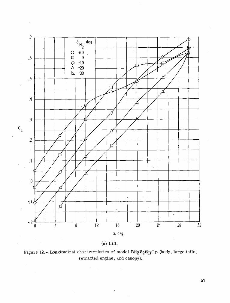
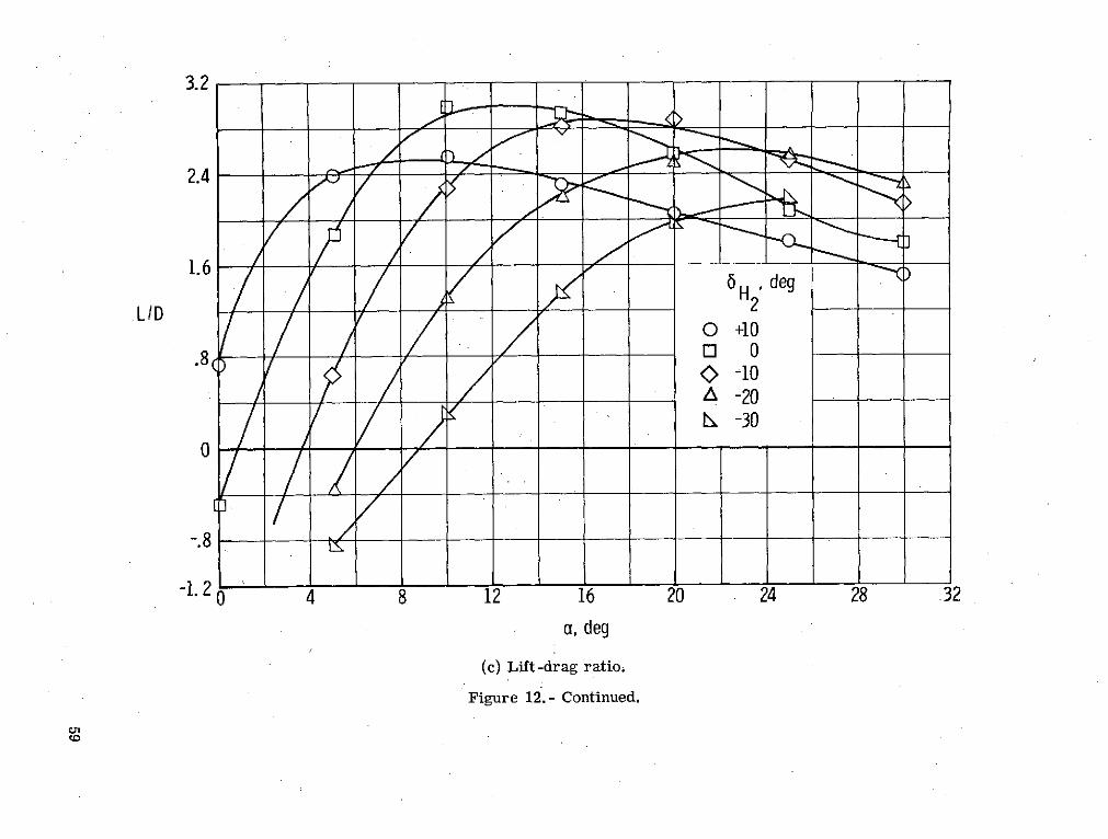
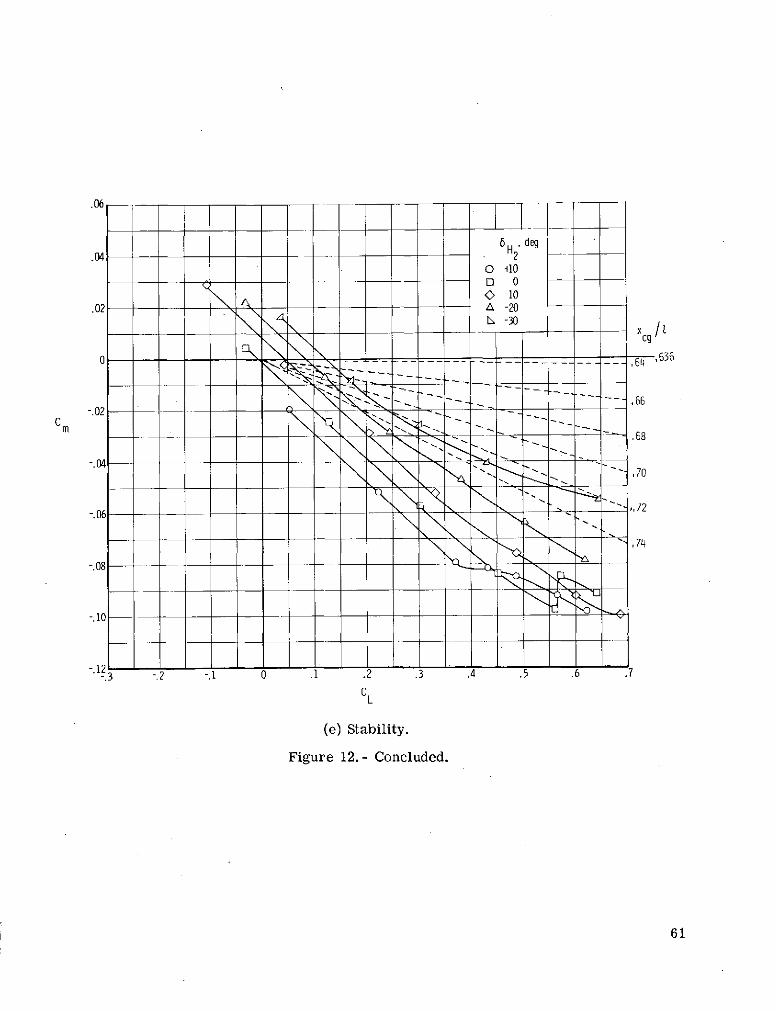
The effects of increasing the horizontal-tail area by 100 percent and the vertical-tail area by 50 percent on the longitudinal control capabilities are shown in figure 12 formodel BH 2 V 2ERCp. This increase in control area markedly increased the lift-curveslope, the drag, and the longitudinal stability, and decreased the lift-drag ratio, as com-pared with the small-tail model of figure 11. This increase in lift may be attributed toboth the increase in model planform area and the increase in planform aspect ratio. Thedrag rise is primarily caused by the increased area of the 50 toed-in vertical tails, but isalso caused by the increased wetted area of the enlarged horizontal tails. The increasedtail-surface area resulted in an even more stable configuration than the small-tail model
8

when the 0.6361 center-of-gravity location was used as a common reference. The trim
capability was identical with that of the model equipped with the small horizontal and
vertical tails; again the model could only trim to a = 130 and a CL,t of 0.125. In this
instance the required rearward shift of the center of gravity was about 9.4 percent body
length to a new center of gravity at 0.731, to trim with 6 H1 = -300 (fig. 12(e)). Because
of the excessively large center-of-gravity shifts required for a reasonable trim range of
the angle of attack, trim plots were considered to be unnecessary for the presentation of
results and, therefore, were omitted.
Static Lateral-Directional Characteristics
The coefficients of side force, rolling-moment, and yawing moment for the basic
BH1V1ERCp model are presented in figure 13 with angle of attack for various fixed
angles of sidelip. At P = 00, the magnitude of the parameters is small and thereby
indicates little or no asymmetry in the model construction or in the flow angularity in
the tunnel. The positive values of rolling moment at low angles of attack for both posi-
tive values of the sideslip angle provide a measure of undesirable negative dihedral
effect; at higher angles of attack the model exhibits the desired negative roll with posi-
tive sideslip angle or positive dihedral effect. Yawing moments are negative throughout
the angle-of-attack range for both sideslip angles. This condition results in a direc-
tionally unstable configuration, which, when coupled with the negative dihedral effect at
low angles of attack, probably causes dynamic instability through that region. It should
-be noted that there is apparent blanketing of the downstream vertical tail by the body cross
flow, as evidenced by the similarity of the yawing moments produced by the 50 and 100
sideslip angles.
Figure 14 shows the variation of the coefficients of side force, rolling moment, and
yawing moment with sideslip angle at a = 00 for the basic model BH1V1ERCp. The
importance of this figure is that it shows all parameters to be approximately linear with
sideslip angle. It was assumed that these lateral and directional parameters were linear
with sideslip angle at all angles of attack and that the slopes obtained from data on various
configurations, measured at 00 and 50 sideslip angles, were valid. The results of the tests
reduced in this manner are presented in figures 15 to 18 for various model configurations.
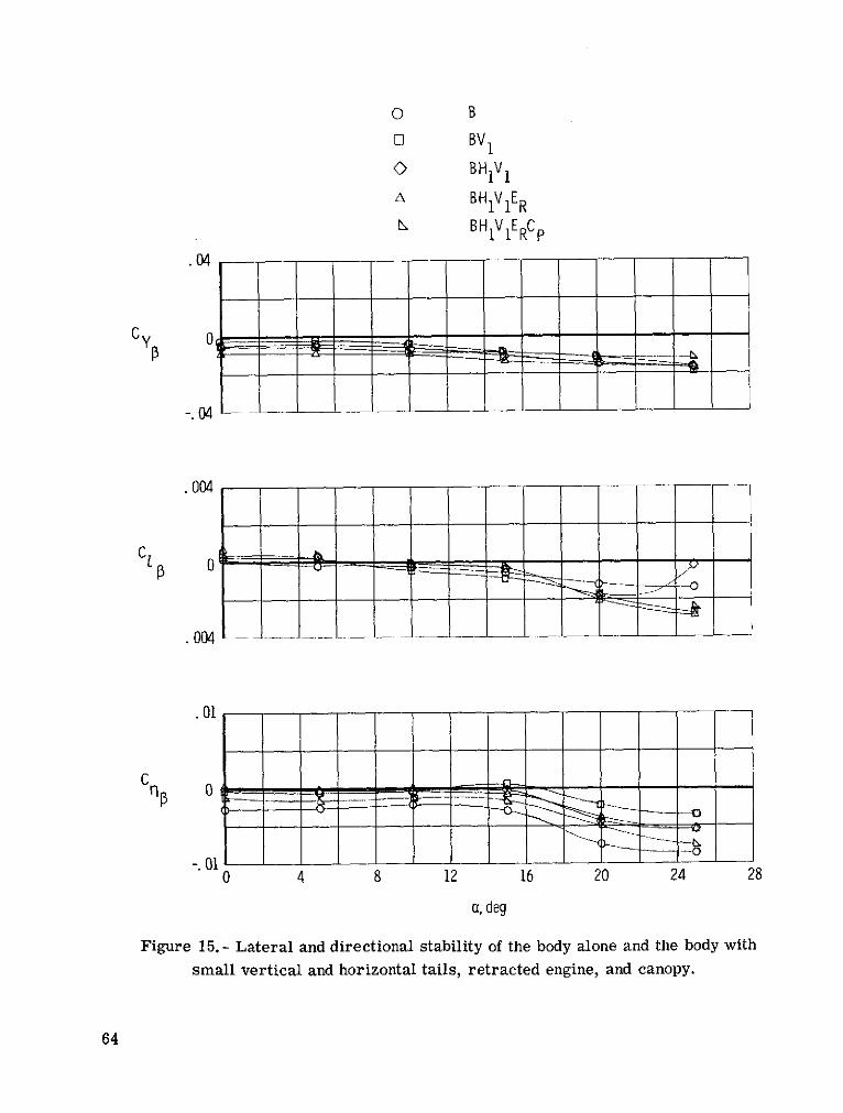
Configuration buildup.- The static lateral and directional stability characteristics
are presented in figure 15 for the body alone with a systematic buildup of components to
the complete basic configuration. Except at the lower angles of attack, all configurations
show positive dihedral effect -Clp up to a = 250. All configurations are unstable
directionally throughout the angle-of-attack range and this instability increases at angles
above 160. It should be noted that the addition of the vertical tails to the basic body
improved the directional stability as expected, but the addition of the horizontal tails
9
adversely affected the conditions. The addition of the retracted engine, which was located
near the center of gravity, had no effect on the directional stability, but the canopy further
increased the instability.
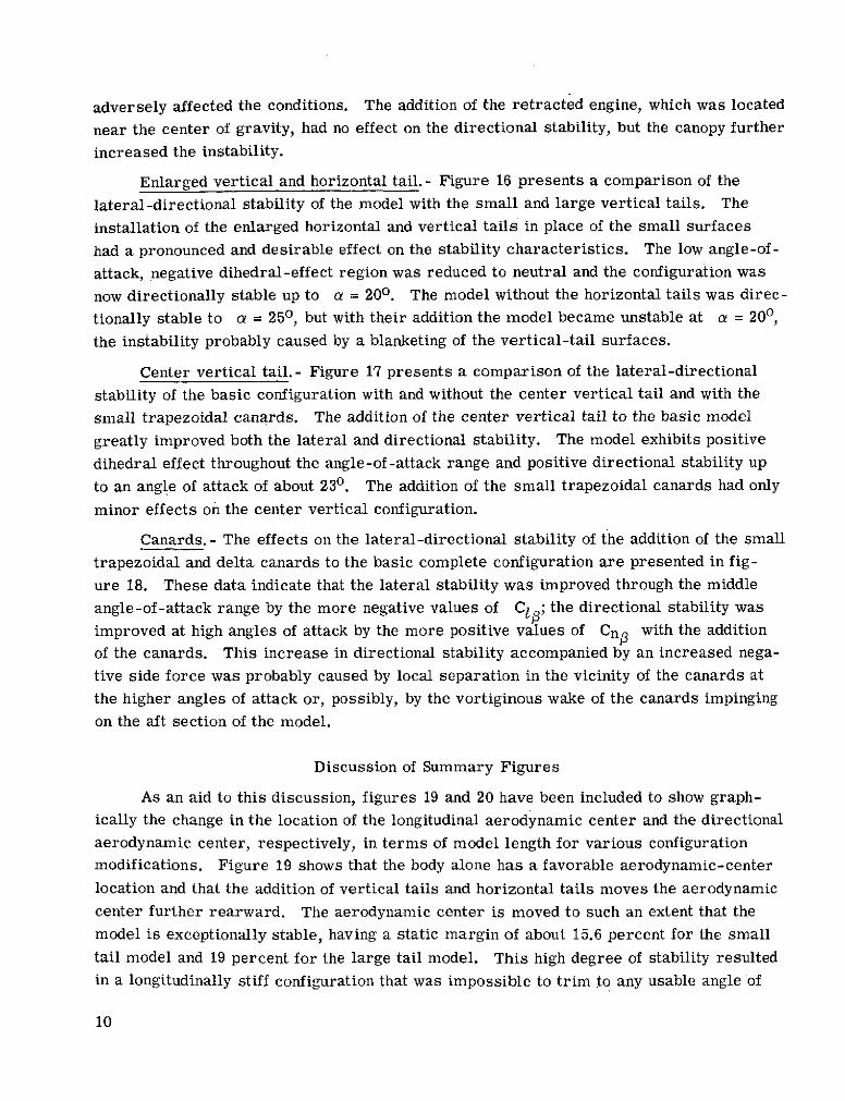
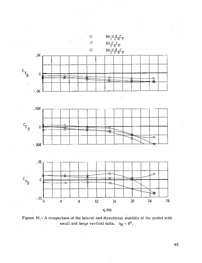
Enlarged vertical and horizontal tail.- Figure 16 presents a comparison of the
lateral-directional stability of the model with the small and large vertical tails. The
installation of the enlarged horizontal and vertical tails in place of the small surfaces
had a pronounced and desirable effect on the stability characteristics. The low angle-of-
attack, negative dihedral-effect region was reduced to neutral and the configuration was
now directionally stable up to a = 200. The model without the horizontal tails was direc-
tionally stable to a = 250, but with their addition the model became unstable at a = 200,
the instability probably caused by a blanketing of the vertical-tail surfaces.
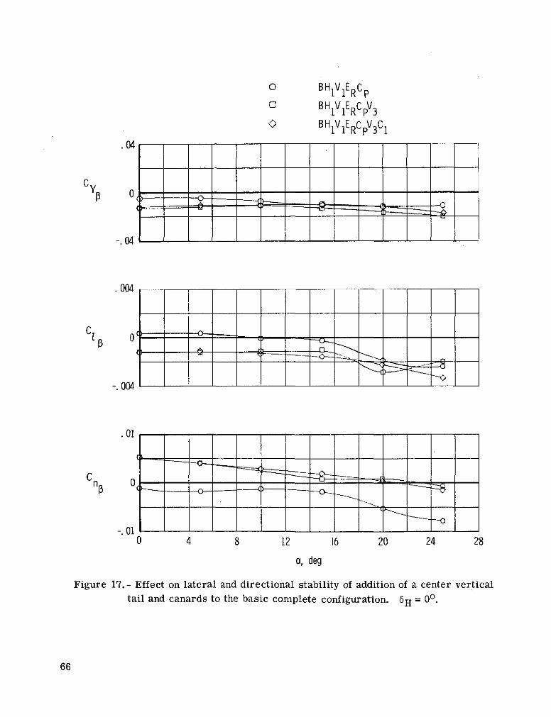
Center vertical tail.- Figure 17 presents a comparison of the lateral-directional
stability of the basic configuration with and without the center vertical tail and with the
small trapezoidal canards. The addition of the center vertical tail to the basic model
greatly improved both the lateral and directional stability. The model exhibits positive
dihedral effect throughout the angle-of-attack range and positive directional stability up
to an angle of attack of about 230. The addition of the small trapezoidal canards had only
minor effects on the center vertical configuration.
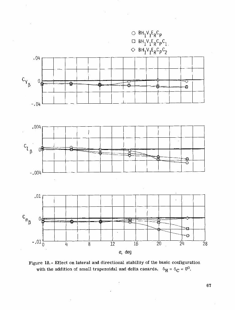
Canards. - The effects on the lateral-directional stability of the addition of the small
trapezoidal and delta canards to the basic complete configuration are presented in fig-
ure 18. These data indicate that the lateral stability was improved through the middle
angle-of-attack range by the more negative values of C1,; the directional stability was
improved at high angles of attack by the more positive values of Cno with the addition
of the canards. This increase in directional stability accompanied by an increased nega-
tive side force was probably caused by local separation in the vicinity of the canards at
the higher angles of attack or, possibly, by the vortiginous wake of the canards impinging
on the aft section of the model.
Discussion of Summary Figures
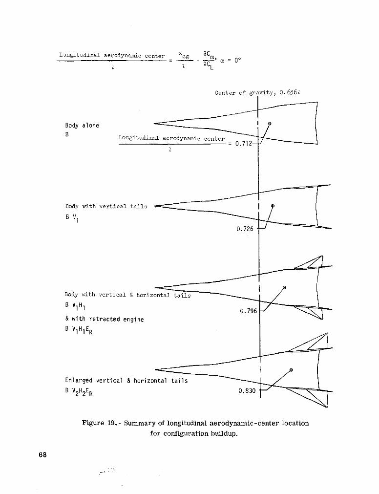
As an aid to this discussion, figures 19 and 20 have been included to show graph-
ically the change in the location of the longitudinal aerodynamic center and the directional
aerodynamic center, respectively, in terms of model length for various configuration
modifications. Figure 19 shows that the body alone has a favorable aerodynamic-center
location and that the addition of vertical tails and horizontal tails moves the aerodynamic
center further rearward. The aerodynamic center is moved to such an extent that the
model is exceptionally stable, having a static margin of about 15.6 percent for the small
tail model and 19 percent for the large tail model. This high degree of stability resulted
in a longitudinally stiff configuration that was impossible to trim to any usable angle of
10
attack with the design center-of-gravity location of 0.6361 as was discussed in the previ-
ous section.
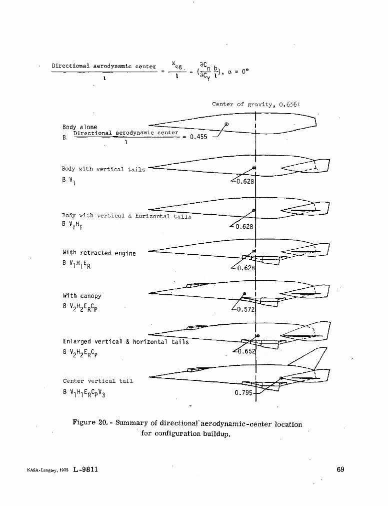
Figure 20 shows that the directional-stability characteristics of the configurations
are diametrically dissimilar to the longitudinal-stability characteristics discussed previ-
ously. The body alone is unstable and the addition of either the small vertical tails, hori-
zontal tails, or retracted engine contributes positively by shifting the aerodynamic center
rearward but not sufficiently to move the aerodynamic center behind the design center
of gravity and produce a directionally stable configuration. The canopy has an adverse
effect. Only by the addition of the enlarged vertical and horizontal tails or by the addi-
tion of the center vertical tail was there success in making the model statically and direc-
tionally stable. The center vertical tail is by far the more efficient stabilizing surface
and has shifted the directional aerodynamic center rearward to 0.7951, which is very
close to the location of the longitudinal aerodynamic center that resulted from the addi-
tion of the small horizontal tails (fig. 19). Thus, if the center. of gravity were moved
rearward to the 0.711 body station, as suggested in the section of this paper entitled
"Longitudinal control characteristics," and a center tail were installed, the configu-
ration would possess both longitudinal and directional stability and would be longi-
tudinally controllable to a = 30 0 . The practicality of such a large shift in the center
of gravity would require a serious design study, but the addition of the rearward
located center vertical tail and the required rearward movement of the main landing
gear would certainly contribute to this design change.
CONCLUDING REMARKS
An experimental investigation of the low-speed longitudinal, lateral, and directional
stability characteristics of a lifting-body hypersonic research airplane concept was con-
ducted at a Reynolds number based on fuselage length of 2 x 10⁶. The configuration was
found to be longitudinally stable without controls and, with the addition of horizontal con-
trols, to be excessively stable; this stability resulted in a longitudinally stiff vehicle that
was impossible to trim to any usable angle of attack with the design center of gravity
location. Conversely, the configuration was directionally unstable with and without the
design vertical controls and required an additional 50-percent vertical-tail area in the
form of enlarged tip fins or a center vertical tail for positive static directional stability.
Therefore, both a rearward shift in design center of gravity for longitudinal control and
an increase in vertical-tail size for directional stability are required for an aerodynam-
ically viable vehicle.
Langley Research Center,
National Aeronautics and Space Administration,
Hampton, Va., November 27, 1974.11
REFERENCES
1. Anon.: Hypersonic Research Facilities Study. Phase I - Preliminary Studies.
Volume II, Part 1 - Research Requirements and Ground Facility Synthesis.
NASA CR-114323, 1970.
2. Anon.: Hypersonic Research Facilities Study. Phase I - Preliminary Studies.
Vol. II, Pt. 2 - Flight Vehicle Synthesis. NASA CR-114324, 1970.
3. Anon.: Hypersonic Research Facilities Study. Phase II - Parametric Studies.
Vol. III, Pt. 2 - Flight Vehicle Synthesis. NASA CR-114326, 1970.
4. Anon.: Hypersonic Research Facilities Study. Phase III - Final Studies. Vol. IV,Pt. 1 - Flight Research Facilities. NASA CR-114327, 1970.
5. Clark, Louis E.: Hypersonic Aerodynamic Characteristics of an All-Body ResearchAircraft Configuration. NASA TN D-7358, 1973.
6. Penland, Jim A.: Creel, Theodore R., Jr.; and Howard, Floyd G.: Experimental Low-Speed and Calculated High-Speed Aerodynamic Characteristics of a Hypersonic
Research Airplane Concept Having a 650 Swept Delta Wing. NASA TN D-7633,1974.
7. Creel, Theodore R., Jr.; and Penland, Jim A.: Low-Speed Aerodynamic Character-istics of a Hypersonic Research Airplane Concept Having a 700 Swept Delta Wing.NASA TM X-71974, 1974.
12
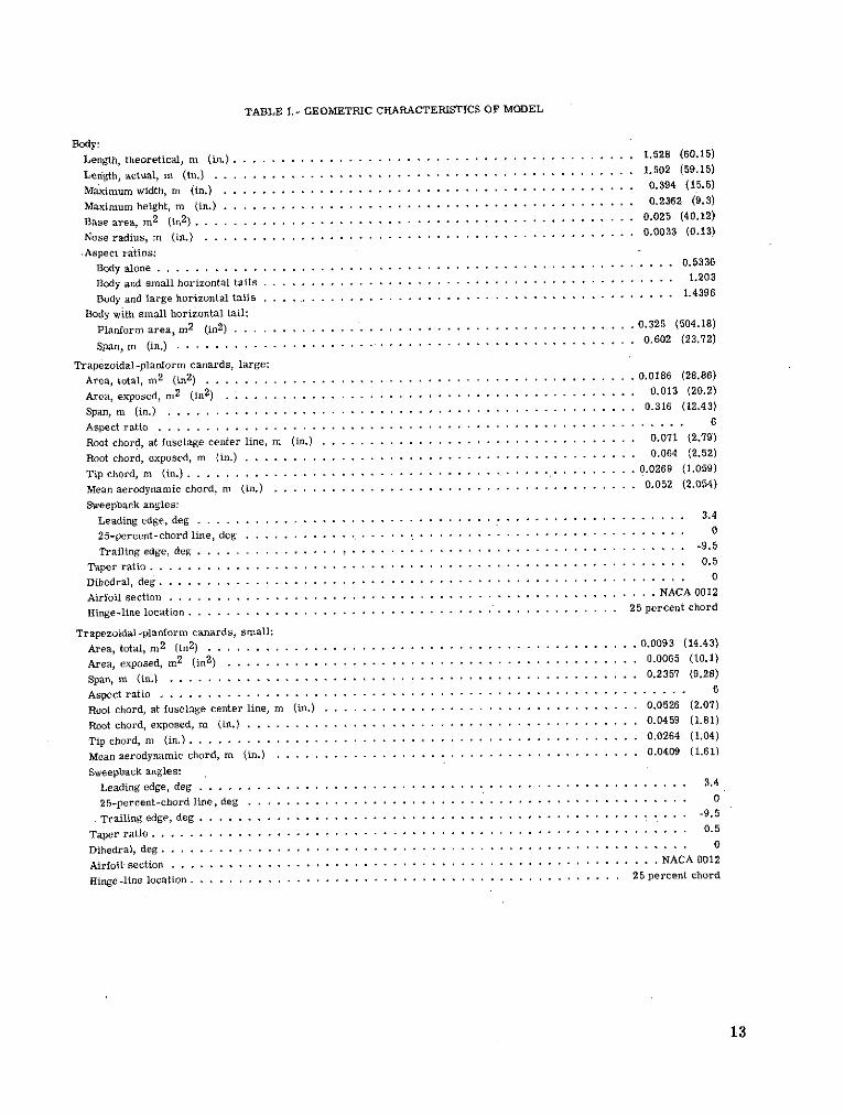
TABLE I. - GEOMETRIC CHARACTERISTICS OF MODEL
Body:
Length, theoretical, m (in.) .......................................... 1.528 (60.15)
Length, actual, m (in.) . ........................................... .1.502 (59.15)
Maximumwidth, m (in.) ....................................... . 0.394 (15.5)
Maximum height, m (in.)............ ........................................ 0.2362 (9.3)
Base area, m2 (in
2) .................................................... . 0.025 (40.12)
Nose radius, m (in.) .............. ................. ............. . 0.0033 (0.13)
Aspect ratios:
Body alone ................ ...... ... .............................................. 0.5336
Body and small horizontal tails . .......... .......... ................................ .... 1.203
Body and large horizontal tails ....... .................................... .... 1.4396
Body with small horizontal tail:
Planform area, m2 (in
2) .............. .................................... . .0.325 (504.18)
Span, m (in.) .................................................. 0.602 (23.72)
Trapezoidal-planform canards, large:Area, total, m
2 (in2
) . ............................................. 0.0186 (28.86)
Area, exposed, m2 (in
2) . . . ............. ... . . . . . . . .. 0.013 (20.2)
Span, m (in.) . ............................................... 0.316 (12.43)
Aspect ratio .. . . . . . . . . ..... . ... . . . . . . . ..- . . .. . . . . . . . . . . . . . .. 6
Root chord, at fuselage center line, m (in.) . . . . . . . . . . . . . . . . . . . . . . . . . . . . . 0.071 (2.79)
Root chord, exposed, m (in.) ......................................... 0.064 (2.52)
Tip chord, m (in.) . . ............ ................. . .... . ................ 0.0269 (1.059)
Mean aerodynamic chord, m (in.) ......... . . . . . ............................. . 0.052 (2.054)
Sweepback angles:
Leading edge, deg . .............. .. .............. . I ... .. ... ....... . 3.4
25-percent-chord line, deg ......... ... .. .. ............... ..... . ......... . 0
Trailing edge, deg ............... !.. .... . ............... . ............. . -9.5
Taper ratio ... . . . . . . . . . . . . . . .. . . . . . . .. . . . . . . . . . . . . .. . . . . . . . . . . .. . . 0.5
Dihedral, deg ........................ ...... . .... . .......... . 0
Airfoil section ............ ....... . ......... . . ................... NACA 0012
Hinge-line location .. ................ .. *-*... * *.. ... .. ........ . 25 percent chord
Trapezoidal-planform canards, small:
Area, total, m2 (in
2) ............................................. 0.0093 (14.43)
Area, exposed, m2 (in
2 ) . ........................................... 0.0065 (10.1)
Span, m (in.) .. ......................................... .... 0.2357 (9.28)
Aspect ratio ............ .. . . . ..... . ................................................. 6
Root chord, at fuselage center line, m (in.) ............. . . . . . . . . . . . . . . . . . . . .... 0.0526 (2.07)
Root chord, exposed, m (in.) . .. . . . . . .. .. ..................................... 0.0459 (1.81)
Tip chord, m (in.)......... ... .. . ........................................... .. 0.0264 (1.04)
Mean aerodynamic chord, m (in.) .. . . . . . . . . . . . . . . . . . . . . . . . . . . . . . . . 0.0409 (1.61)
Sweepback angles:Leading edge, deg ........... . . . . ...................................... 3.4
25-percent-chord line, deg ........................ ...... ................. 0
Trailing edge, deg .............. .................................................. -9.5
Taper ratio.................. ........................................... 0.5
Dihedral, deg ..................... .- . . . . . . . . . . ......... .. .... .. 0
Airfoil section .......... ................. . ...................... ..... NACA 0012
Hinge-line location ................ . .......................................... 25 percent chord
13
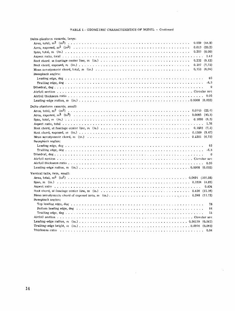
TABLE I.- GEOMETRIC CHARACTERISTICS OF MODEL - Continued
Delta-planform canards, large:
Area, total, m2
(in2
) .................................... .. . .. ... 0.029 (44.8)
Area, exposed, m2
(in2
) ........................ ....... ........... 0.013 (20.2)
Span, total,m (in.) ................ .............................. 0.203 (8.00)
Aspect ratio, total .......... ....................... .................. 1.43
Root chord, at fuselage center line, m (in.) ................... .......... . . 0.232 (9.12)
Root chord, exposed, m (in.) ............... .... .................. ... 0.197 (7.75)
Mean aerodynamic chord, total, m (in.) .............. ... ............... . . 0.153 (6.04)
Sweepback angles:
Leading edge, deg ....................... ...... ....... .............. 65
Trailing edge, deg .............. .................................... -6.5
Dihedral, deg ..... ..... .. .. .... ....... ....... . . . .............. .. ... 0
Airfoil section ...................................... ............ Circular are
Airfoil thickness ratio ................... ........ ........ ............. 0.05
Leading-edge radius, m (in.) .................. ............ .......... 0.0008 (0.032)
Delta-planform canards, small:
Area, total, m2 (in
2) ......................... . ............. .... 0.0145 (22.4)
Area, exposed, m2 (in
2) ......... .................... ............ . 0.0065 (10.1)
Span, total, m (in.) .................... ... .. ... ............... 0.1600 (6.3)
Aspect ratio, total .......... .......................... ............. 1.76
Root chord, at fuselage center line, m (in.) . .................. ..... ......... . 0.1803 (7.1)
Root chord, exposed, m (in.) ...................................... ... 0.1389 (5.47)
Mean aerodynamic chord, m (in.) .......... ...... ..................... 0.1201 (4.73)
Sweepback angles:
Leading edge, deg ............................. ...... ... ................ 65
Trailing edge, deg ................... ...................................... -6.5
Dihedral, deg ............ .. .... ....... . .... . . . .. ... ... ........ 0
Airfoil section ........... ....... ... .............. ............. Circular arc
Airfoil thickness ratio .................. .............. ..... ........... 0.05
Leading-edge radius, m (in.) ........................ .............. ... 0.0008 (0.032)
Vertical tails, twin, small:
Area, total, m2
(in2
) ........... . .... .. .. . ... . ............ . 0.0691 (107.08)
Span, m (in.) . . . . . .. . . . . . . . . . . . . . . . . . . . . . . . . . . . . . . . . . . . . .. . .. 0.1224 (4.82)
Aspect ratio . ............ . .. . .. ................ ... ................. . . 0.434
Root chord, at fuselage center line, m (in.) ................... ............. 0.436 (17.16)
Mean aerodynamic chord of exposed area, m (in.). . .................. ... . . . ... .. 0.298 (11.72)
Sweepback angles:
Top leading edge, deg ...................................... . ........ . 78
Bottom leading edge, deg ............ ...... . ....... . .. .... .. ......... 14
Trailing edge, deg ............................. ......... ............. 11
Airfoil section ................. . ............................... Circular arc
Leading-edgeradius, m (in.) .......................... . ............. 0.00119 (0.047)
Trailing-edge height, m (in.) ........... . ........ ............... ... 0.0016 (0.063)
Thickness ratio ........................... . .. ... . ..... ............ 0.04
14
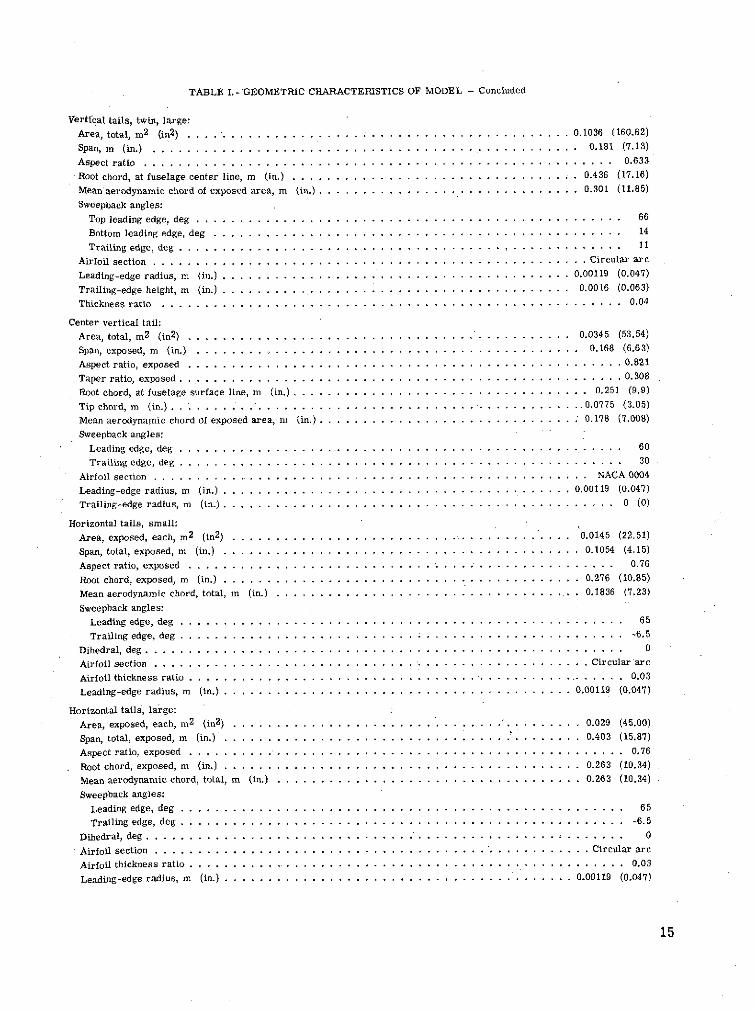
TABLE I.- GEOMETRIC CHARACTERISTICS OF MODEL - Concluded
Vertical tails, twin, large:
Area, total, m2
(in2 ) ...... ............. ......................... 0.1036 (160.62)
Span, m (in.) .......... . ............ .... ........ 0.181 (7.13)
Aspect ratio ........................... ... . . ......... ........ .. 0.633
Root chord, at fuselage center line, m (in.) ............... ......... . . . .. . 0.436 (17.16)
Mean aerodynamic chord of exposed area, m (in.) . . . . . . . . . . ............. ..... . . . . . . . . . 0.301 (11.85)
Sweepback angles:
Top leading edge, deg ........................ . ... .......... ........... 66
Bottom leading edge, deg .................................... .......... . 14
Trailing edge, deg ................... ..... . . ....... ....... ......... 11
Airfoil section ................... . . .. ................ .......... ... Circular arc
Leading-edge radius, m (in.) .................. ...... . . . . . . . . . . . . .... 0.00119 (0.047)
Trailing-edge height, m (in.) .. ......... .. .. ..... .............. 0.0016 (0.063)
Thickness ratio ......... .......... . . ... . ........... 0.04
Center vertical tail:
Area, total, m2
(in2) ................ .... ........ ........... 0.0345 (53.54)
Span, exposed, m (in.) ............ . ....... . ... ..... ........ 0.168 (6.63)
Aspect ratio, exposed ... . . . . ...................... . . . . . . . . . . . . . . . . . . . . . . 0.821
Taper ratio, exposed. .. ..... . . . . ..... .. .. .. . . .... . . . . . . . . . . . . . . . 0.308
Root chord, at fuselage surface line, m (in.) . . . .......................... . . . . .. . . .. . 0.251 (9.9)
Tip chord, m (in.) .. ...... .... .......... . .. ...... .. .......... .......... 0.0775 (3.05)
Mean aerodynamic chord of exposed area, m (in.) . .................. ... . . . ... 0.178 (7.008)
Sweepback angles:
Leading edge, deg ................... . . ...................... ...... .... 60
Trailing edge, deg ...... ............ ..... ..... . ................... 30
Airfoil section ......... ............ .. ...... . ........ ........... NACA 0004
Leading-edge radius, m (in.) ................... ..... .. . . . . . . . . . . . 0.00119 (0.047)
Trailing-edge radius, m (in.) .................................... .... . ..... .... 0 (0)
Horizontal tails, small:
Area, exposed, each, m2
(in2
) ...................... ........ ............. 0.0145 (22.51)
Span, total, exposed, m (in.) ............ ........... .. .. .. ......... 0.1054 (4.15)
Aspect ratio, exposed .................. ... ..... ..... .. ... ... ........ 0.76
Root chord, exposed, m (in.) . .................. . . . . . . . . . . . . 0.276 (10.85)
Mean aerodynamic chord, total, m (in.) ................... ....... . .. ..... . . 0.1836 (7.23)
Sweepback angles:
Leading edge, deg .. . ....................... . .. ... .. .. ..... .. 65
Trailing edge, deg ................... . . .... . . .. ........... ........... -6.5
Dihedral, deg ........... .......... .................... ... .. .......................... 0
Airfoil section ............................... . . .. . ......... . . ... ............ Circular arc
Airfoil thickness ratio ................... ........... . ............ ......... 0.03
Leading-edge radius, m (in.) . . . . . . . ....... ........ .... . . ...... . . 0.00119 (0.047)
Horizontal tails, large:
Area, exposed, each, m2
(in2
) ................. .. ..................... 0.029 (45.00)
Span, total, exposed, m (in.) .................... .................... 0.403 (15.87)
Aspect ratio, exposed ...................... .... ........... ....... 0.76
Root chord, exposed, m (in.) ................... ................. ... 0.263 (10.34)
Mean aerodynamic chord, total, m (in.) ................... ............... 0.263 (10.34)
Sweepback angles:
Leading edge, deg ................... .............. .......... 65
Trailing edge, deg ......................... .......... . . ............ -6.5
Dihedral, deg ................ . ........ .... ........ ...... . .. . ....... 0
Airfoil section ............... ... ................ ...... . ........... Circular are
Airfoil thickness ratio ......................... ..... .. ... ........ ....... 0.03
Leading-edgeradius, m (in.) ........................................ 0.00119 (0.047)
15
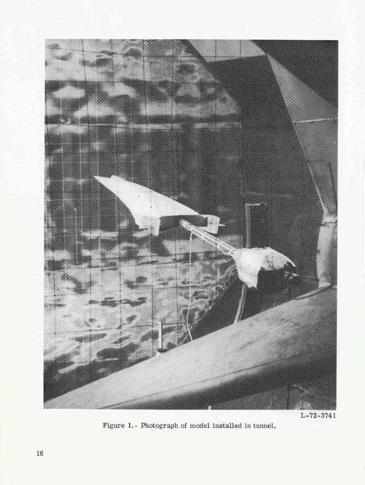
L-72-3741Figure 1.- Photograph of model installed in tunnel.
16

Stationx/L1 2 4 1. 0 1. 0 0
.233 .909
.37 797.395
499 50.599.710 80
Station x/I
0 .124 .233 .374 .499 .599 .710 .797 .909 1.00
-636
Scramjet retracted
Scramjet open
(a) Complete model.
Figure 2.- Details of wind-tunnel model. All dimensions are normalized by the fuselage length L.
H -. 051 1-
Rd. L./0 0t1xad0=2 / .59
S042838
Rad. = .002 Rad. = 00213
.3 1
71. 5o . .043..,.__- - -- 2 -
H. L. H.L. at x/ 1 ." 98( and .58 cr,exp 136
(b) Center vertical tail and small and large trapezoidal and delta canards.
H.L. denotes hinge line.
Figure 2.- Continued.
18
.179 255
X/ 0.972
.797 .847 .909 .946 1.000 1.043 1.081 1.094 .797 .847 .909 .946 1.000 1.048 1.081 1.100
x/[ xlt
(c) Small and large horizontal and vertical tails.
Figure 2.- Concluded.
Mx
RELATIVE WIND
Figure 3.- Systems of reference axes; arrows indicate positive directions.
O B.7 O BV1
0 BH1V1
L BH V E.6 I R
a BHIVIER
.5 A BH2V2ERCp
.4
C L
.3
.2
0 4 8 12 16 20 24 28 32
a, deg
(a) Lift.
Figure 4.- Longitudinal characteristics of the body alone and the body with
various horizontal and vertical tails. 6H = 00.
21
.4 - --
O B
O BV1
0 VI V1
, BH1V1E R _
.3 l BH1V1ERO BH V 1E RC
a BH2V2ERCp
CD .2
0 4 8 12 16 20 24 28 32
a, deg
(b) Drag.
Figure 4.- Continued.
22
O B
O BV1
0 BH IVL BH1 V E1 lo
1I BHIV ERo BH1V1ERCP
A BH2V2ERCP4.0
3.2
2.4
0 -
0 4 8 12 16 20 24 28 32
a, deg
(c) Lift-drag ratio.
Figure 4.- Continued.
23
OB
O BV1
110 BH V E
L BH1V1E R
o BH V1ERC p
A BH2V 2ERCP
.02
0
.02
m -.04
.06
-.08
-.100 4 8 12 16 20 24 28 32
a, deg
(d) Pitch.
Figure 4.- Continued.
24
O B
o BVI
I1SBH V EI
L, BHIVIE R1 BH1V1ER
0 BHIVIERCP
A BH2V2ER C.04
.02
0
.02
m
.04
-.06
.08
.10.2 -.1 0 .1 .2 .3 .4 .5 .6 .7
L
(e) Stability.
Figure 4. - Concluded.
25
.3
CD
0 Bo BV10 BH1V1
BH1V ERC pBH2V2ERC
p
0 .1 .2 .3 .4
CL2
Figure 5. - The drag due to lift of the body alone and the body with vertical and horizontal tails,retracted engine, and canopy. 5H = 00.

.7O BH1V1ERC
0 BHIV1ER C 3
.6 L BH1V1ERC P V3C !
.5
a, deg
(a) Lift.
Figure 6.- Effect on longitudinal characteristics of addition of the center vertical tail
and small trapezoidal canards to the BH1V1ERC p configuration. 5H = 00.
2727
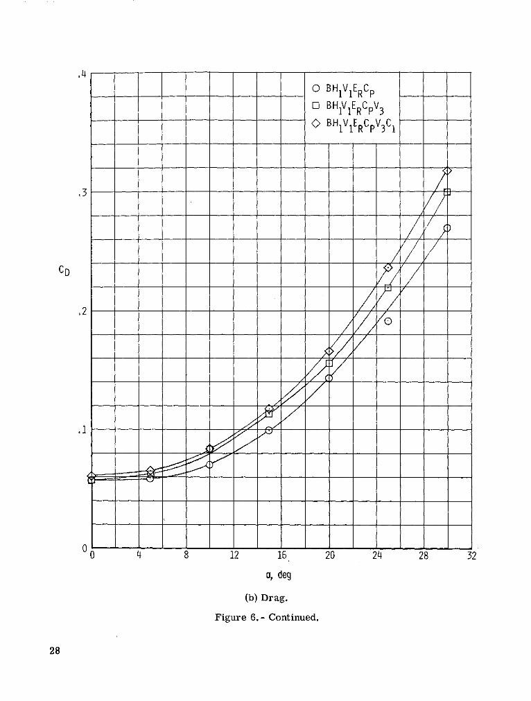
,4
O BHIV E RCp
O BH1V1ERCpV3
0 BH1V1ERCpV3C 1
3P]
CD
/
0 8 12 16 20 24 28 32
a, deg
(b) Drag.
Figure 6.- Continued.
28
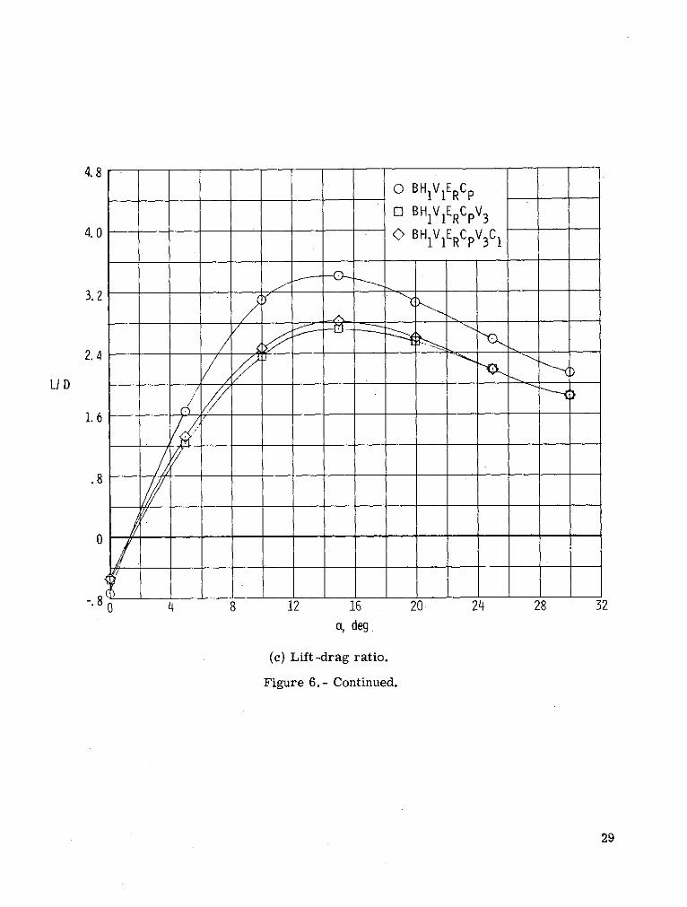
4. 8o BH IVERC
O BHIV1ERC pV34.0
-O BH1V1ERCpV3C 1
3.2
2.4
L/ D
1. 6
.8
.8 8 12 16 20 24 28 32
a, deg
(c) Lift-drag ratio.
Figure 6.- Continued.
29
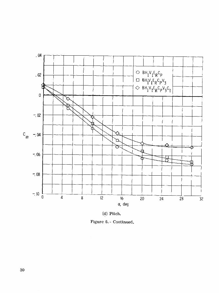
.04
.02 0 BHIV 1ERC pE] BHIVIERCpV
3O BH1V ERCpV3 C
-02
c - 04
- 08
0 4 8 12 16 20 24 28 32a, deg
(d) Pitch.
Figure 6.- Continued.
30
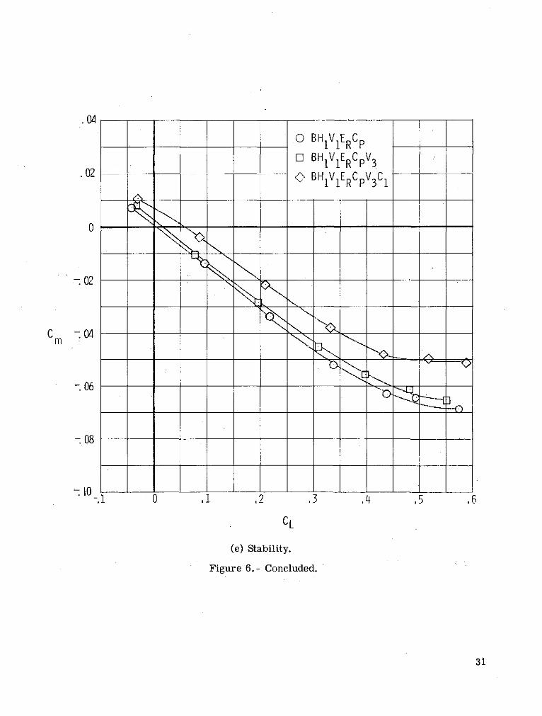
O BHIV E RCp
O BH1IV1ERCpV 3
.02 O BHIVIERCpV3C1
0 -
.02
C -04 _Cm
- 06
- 08
.1 0 ,1 ,2 ,3 ,4 ,5 ,6
CL
(e) Stability.
Figure 6.- Concluded.
31
.7 -OBO BV2ERCp
.6 O BH2V2ERCp
5 -X
CL -
1 0 4 8 12 16 20 24 28 32
a, deg
(a) Lift.
Figure 7.- Effect on longitudinal characteristics of addition of the large horizontal
tail H2 to the BV2ERCP configuration. 6 H = 00.
32
O BO BV2ERC p
O BH2V2ERC p
CD
0 4 8 12 16 20 24 28 32
a, deg
(b) Drag.
Figure 7.- Continued.
33
4. 8<>BO BV2ERC
p
4.0 ] BH2V2ERCp
3. 2
2.4
1. 6
.8
0
.0 4 8 12 16 20 24 28 32
a, deg
(c) Lift-drag ratio.
Figure 7.- Continued.
34

<>BO BV ERC p
.02 O BH2V2ERCp
04
0 8 12- 06 -
- 08 ,
-I0 0 4 8 12 16 20 24 28 32
a, deg
(d) Pitch.
Figure 7.- Continued.
35

OB
0 BV2ERCP
02 0 BH2V2ER C
S - 02
m ___
06
- 08
10. 0 ,1 ,2 ,3 ,4 ,5 ,6 ,
(e) Stability.
Figure 7.- Concluded.
36
7 B H1V1 ER Cp
SB H 1V1 ER Cp C1
.6 O B H1V 1 ER Cp C2 AB H1V1 ER Cp C3
5 B H1V1 ER Cp C4
.4 -_
CL .3
.1 -
0 4 8 12 16 20 24 28 32a, deg
(a) Lift.
Figure 8.- Longitudinal characteristics of model BHV1lERCp (body, small tails,retracted engine, and canopy) with various canards. 6C = 6H = 00.
37
.3o B H1V1 ER Cp
SB H11 ER CpC10 B HIV 1 ER Cp C2
AB HIV1 ER Cp C3
LB H1V1 ER Cp C4
CD
0 4 8 12 16 20 24 28 32
a ,deg
(b) Drag.
Figure 8.- Continued.
38
4.0
3.2
2.4
OB HIV1 ER C
_D 1.6 OB HIV1 ER C C1
0 B H1V1 ER Cp C2
8B HIV ER C C3
B H1V1 ER CP C4
0 -
-1. 20 4 8 12 16 20 24 28 32
a, deg
(c) Lift-drag ratio.
Figure 8.- Continued.
.06o B H1V 1 ER Cp
O B HIV 1 ER Cp C.04 O B HIV 1 ER Cp C2
A B HIV 1 ER Cp C3
.02 B HV ER Cp C4.02 -
C
.02
-.04
-.06
-.080 4 8 12 16 20 24 28 32
a. deg
(d) Pitch.
Figure 8.- Continued.
40
.06
O B H1V 1 ER Cp
O B H1V I ER Cp C1.04 O B H1V I ER Cp C2
A B H1V 1 ER Cp C3I- B H1V l E Cp C4
.02
.02
.04
-06-.06 "____._ __._
-.08 J -
-.1 .1 .2 .3 .4 5 .6 .7CL
(e) Stability.
Figure 8.- Concluded.
41
.7 _ __I
6 C, deg
6 0El +50 +10
.5 -_ +15
CL .3
.1
0 4 8 12 16 20 24 28 32
a, deg
(a) Lift.
Figure 9.- Longitudinal characteristics of model BH1VlERCpC 1 (body, small tails,retracted engine, canopy, and small trapezoidal canards). 6H1 = 00 .
42
.3
6C 1, deg
0 0045O +10a +15
CD.2
0 4 8 12 16 20 24 28 32
a,deg
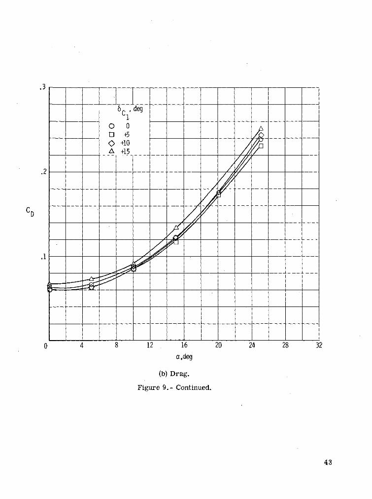
(b) Drag.
Figure 9.- Continued.
43
3. 2
2.4
1.6 ClL 1C , degL / D
O +10a +15
-1. 20 4 8 12 16 20 24 28 32
a, deg
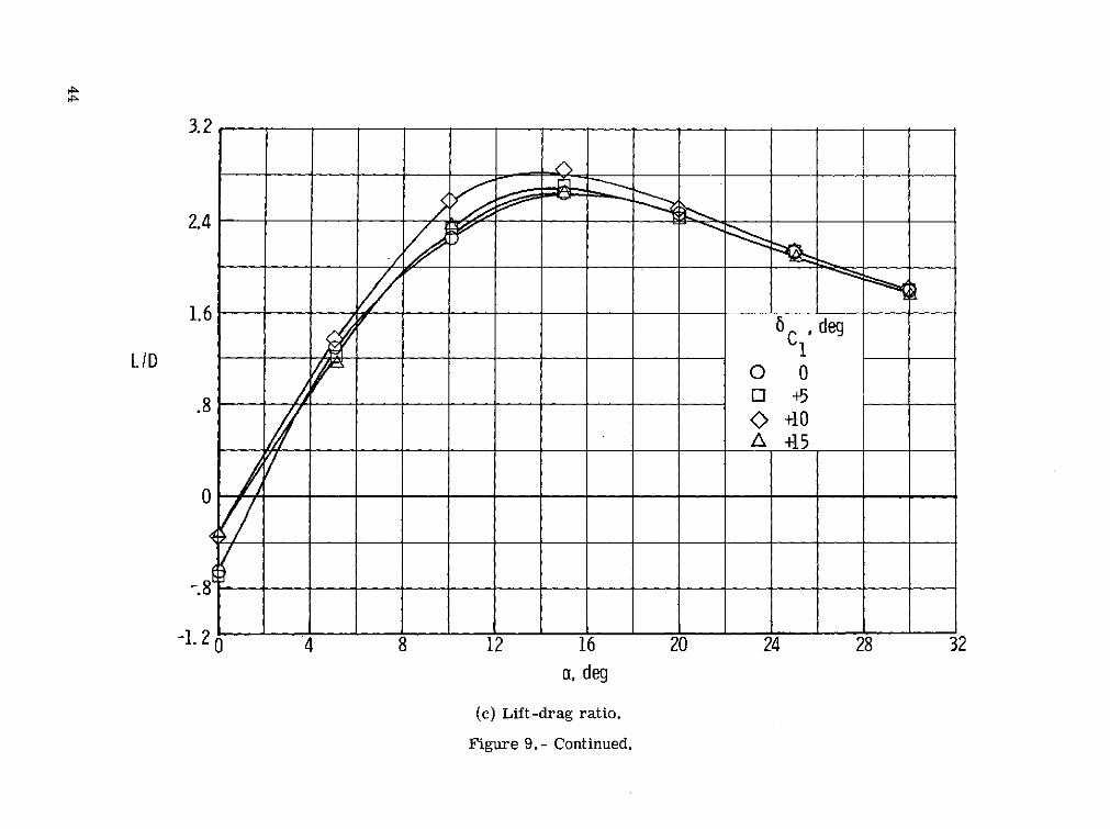
(c) Lift-drag ratio.
Figure 9.- Continued.
.06
C 1, deg04
O 0c +5O +10
.02 A +15
0-
C m -.02Cm -02
.04 ,,
-.06
-.08
.100 4 8 12 16 20 24 28 32a, deg
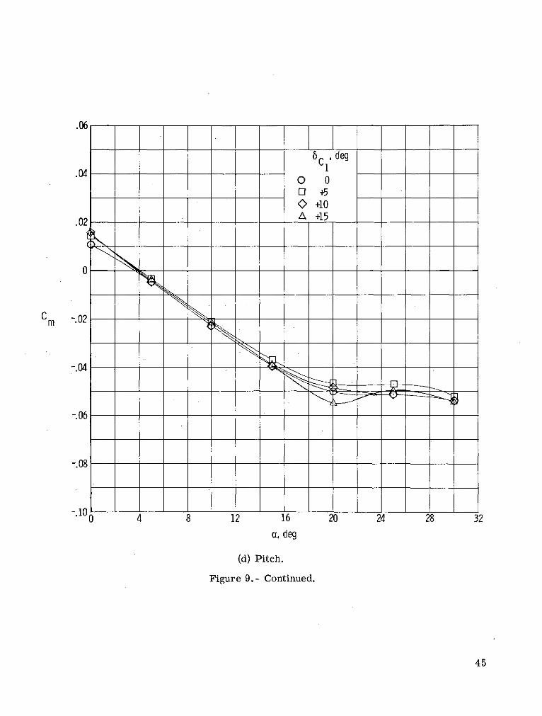
(d) Pitch.
Figure 9.- Continued.
45
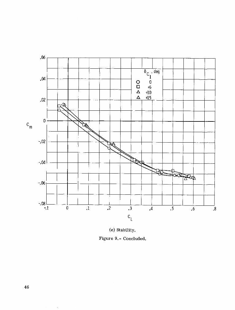
.06
6C , deg.04 1
0 03 +5
A +10
.02 A +15
0Cm
-.02
-.04
-.06
-.08.1 0 .1 .2 .3 .4 .5 .6 .8
CL
(e) Stability.
Figure 9.- Concluded.
46

.6
.5
.4 _
0 0
L / I < +10.2 A +15
-.2 0 4 8 12 16 20 24 28 32
a, deg
(a) Lift.
Figure 10.- Longitudinal characteristics of model BH1V1ERCpC 2 (body, small tails,retracted engine, canopy, and small delta canards).
47
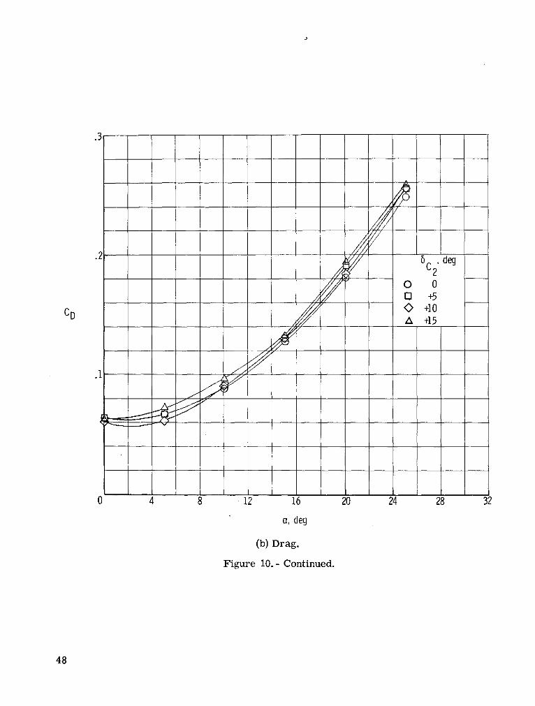
.3-
6 C, deg
0 0C Q +5
CD 0 +10A +15
0 4 8 12 16 20 24 28 32
a, deg
(b) Drag.
Figure 10.- Continued.
48
3.2
2.4
1.6
LI/D .8 +
-.8
-1. 2-1.0 4 8 12 16 20 2
a, deg
(c) Lift-drag ratio.
Figure 10.- Continued.
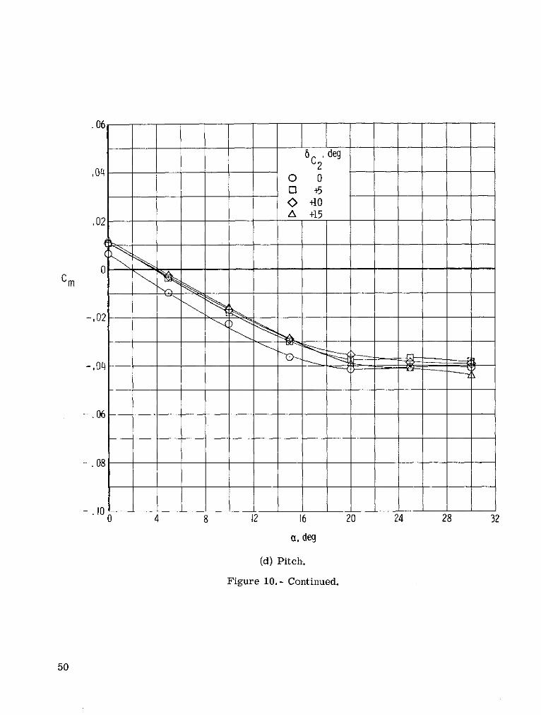
.06
6 . deg
040
* +15
.02 -A +15
,02
-,04
-. 06
-. 08
-. 00 4 8 12 16 20 24 28 32
a, deg
(d) Pitch.
Figure 10.- Continued.
50
.04 deg
C20 00 5
.02 _ + 5A +15
0
.02
.04 -
.06
.08
-.10-10.2 -.1 .1 .2 .3 .4 . .6 .7
CL
(e) Stability.
Figure 10.- Concluded.
15
6 , deg
,1 _
0 +10CL 0 +5 El
LO 0
L -10
0 -20-IN 0 -25
0 -30
0 4 8 12 16 20 24 28 32a, deg
(a) Lift.
Figure 11.- Longitudinal characteristics of model BH1V1ERCp (body, small tails,retracted engine, and canopy).
52
6 , deg
o +10i] +5 7
0A -5,1 -10 //
,] -15Q -20
.2 Q -25O' -30 /
D .I / / 7
C 0
0 4 8 12 16 20 24 28 32
a, deg
(b) Drag.
Figure 11.- Continued.
53
4,0
3,2 _ _ _
2,4
1,6 / /
S6. deg,8 i - C n
/ / +10
L/D 0 A -5
Ia -150 -20
0 -30
-1. 604 8 12 16 20 24 28 32
a, deg
(c) Lift-drag ratio.
Figure 11.- Continued.
54
, 066 H deg
H1'
0 +1004, 06 0 + 5
-10.02 -15
20
-30
-. 06 -- 7 -
-,080 4 8 12 16 2 24 28 32
a, deg
(d) Pitch.
Figure 11.- Continued.
55

,066 H1. deg
0 +10.04 0 45
O 0a -5L -10
.02 L -15o -200 0-25 x/
-30 cg
m 0 - - .636
.66-.02 _ _ ____
- 0 - .68
.70
.72
-. 06
-.08-.2 -,1 0 1 .2 .3 .4 5 .6
CL
(e) Stability.
Figure 11.- Concluded.
6 .H 2 deg
0 +10.6 O 0 0
1-1A -20
5 -30
-2
0 4 8 12 16 20 24 28 32
a, deg
(a) Lift.
Figure 12.- Longitudinal characteristics of model BH2V 2 ERCp (body, large tails,retracted engine, and canopy).
57

.46 H, deg
O +10D 0S-O10- -20I -30
.3 , _ _
CD .2
0 4 8 12 16 20 24 28 32
a ,deg
(b) Drag.
Figure 12.- Continued.
58
LID0 +10
.8 -10-20
L -30
0 4 8 12 16 20 24 28 32
a, deg
(c) Lift-drag ratio.
Figure 12.- Continued.

.08
.06 . H , deg
.0-20L -30
.02
0m -
-.06 -- - __
.08
0 4 8 12 16 20 24 28 32
a, deg
(d) Pitch.
Figure 12.- Continued.
60
.06
6 , deg.04 2 2 -
O +10o 00 -10
.02 A -201 -30 Xg
0 N - ---- - ------ 636
-.02 ,
68
.70
,72-.06
.08
-.10 --
.12 - 2 -.1 .1 .2 .3 .4 .5 .6 .7
C
(e) Stability.
Figure 12.- Concluded.
61

Cy O
-. 2
CL -.004 5, 0 'deg
.06\ [] +5
-.008 - +10
-. 02 -
-.040 4 8 12 16 20 24 28 32
a, deg
Figure 13.- Variation of side force and rolling and yawing moments with angle of
attack at various angles of sideslip for B1H1V1ERCp.
62

.2
C 0
-. 2
.04
C
-. 04
. 01 -
Cn 0 -
-. 01-12 -8 -4 0 4 8 12
3, deg
Figure 14. - Variation of side force and rolling and yawing moments with
sideslip angle for BH1V1ERCp. a = 00.
63
0 B
0 BV1
0 BHIV 1
A BH1V1E R
n BH1 ERCP
.04
Cy 0
-. 04
.004
S004
.01
Cr 3 0
0 4 8 12 16 20 24 28
a, deg
Figure 15. - Lateral and directional stability of the body alone and the body with
small vertical and horizontal tails, retracted engine, and canopy.
64
0 BHIV1ERCP
ED BV2ERCp
O BH2V2ERCP.04
CY 0
-. 04
. 004
CL 0 -----
-. 004
C-------------------- . ---------------.
.01
C n 0
0 4 8 12 16 20 24 28
a, deg
Figure 16.- A comparison of the lateral and directional stability of the model with
small and large vertical tails. 6H = 00
65
O BH1V1ERCP
El BH1V1ERCPV3
O BHIVIERCpV3C1
.04
-.04
.004
C 0 --
-. 004
.01
n.0 - - -- ----- ------ - --.-
-.010 4 8 12 16 20 24 28
a, deg
Figure 17.- Effect on lateral and directional stability of addition of a center verticaltail and canards to the basic complete configuration. 6
H = 00.
66
O BH IVERCp
O BHIV1ERCpCI.
0 BHI VERCpC2
.04
,004
-,004
,01
Cn 0
-. 010 4 8 12 16 20 24 28
a, deg
Figure 18.- Effect on lateral and directional stability of the basic configuration
with the addition of small trapezoidal and delta canards. 5H = 6C = 00.
67
Longitudinal aerodynamic center x cg m _= a = 0
S CL
Center of gravity, 0.6361
Body alone
B Longitudinal aerodynamic center 0.7120.712
Body with vertical tails
B V1
0.726
Body with vertical & horizontal tails
B V1H1 0.796& with retracted engine
B V1HIER
Enlarged vertical & horizontal tails
B V2 H2 ER 0.830
Figure 19.- Summary of longitudinal aerodynamic-center location
for configuration buildup.
68
Directional aerodynamic center xcg aCn b( ), x = 0I i aCy t
Center of gravity, 0.636
Body aloneDirectional aerodynamic center
1
Body with vertical tails ~
B V1 0628
Body with vertical & horizontal tails
B VH1 0.628
With retracted engine
B V1 H 0.6ER2
With canopy
B V2H2 ERCP 0.572
Enlarged vertical & horizontal tails
B V2H2ERCP .65
Center vertical tail
B V1H 1 ERCpV 3 0.795
Figure 20.- Summary of directional aerodynamic-center locationfor configuration buildup.
NASA-Langley, 1975 L-9811 69
ERRATA
NASA Technical Note D-7851
LOW-SPEED AERODYNAMIC CHARACTERISTICS OF A LIFTING-BODY
HYPERSONIC RESEARCH AIRCRAFT CONFIGURATION
By Jim A. Penland and Theodore R. Creel, Jr.
February 1975
Page 17: Replace figure 2(a) with the attached figure 2(a).
Issued September 1975
Stationx/t
.12 4 0. 0 0.233 .909.374 .797
99_- - .395
.499 83. 50
.710 A 800
Station x/. 650
0 .124 .233 .374 .499 .599 .710 .797 .909 1.00.636
Scramjet retracted
Scramjet open
(a) Complete model.
Figure 2.- Details of wind-tunnel model. All dimensions are normalized by the fuselage length ..