low sey engineered surface for electron cloud mitigation sihui wang phd student of loughborough...
TRANSCRIPT
Low SEY Engineered Surface for Electron Cloud Mitigation
Sihui WangPhD student of Loughborough University
University Supervisor: Mike D. Cropper
ASTeC supervisor: Oleg B. Malyshev
Reza Valizadeh

Outline
• Background• Objective• My PhD contents• Examples of SEY Measurements on laser
treated samples• Summary
2
3
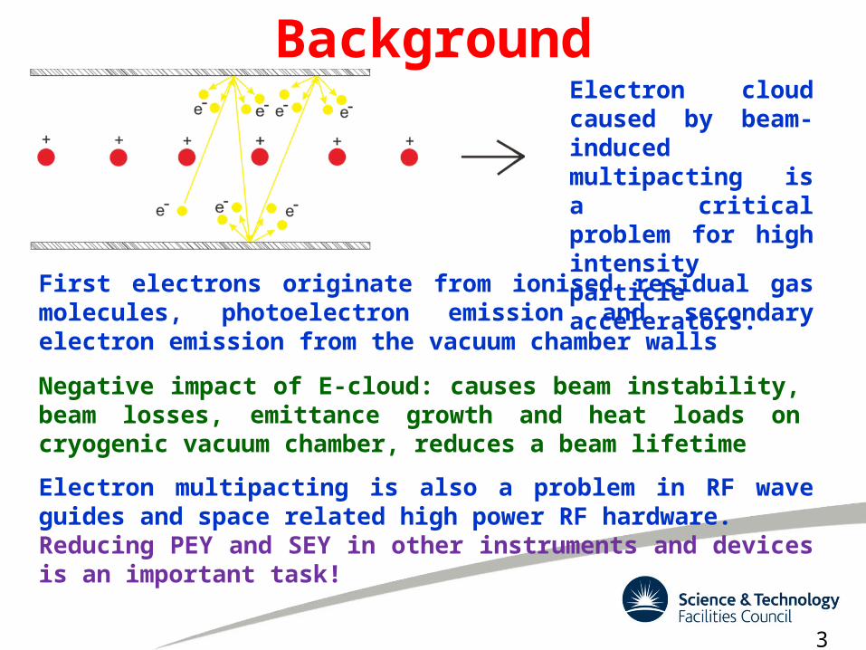
BackgroundElectron cloud caused by beam-induced multipacting is a critical problem for high intensity particle accelerators.
Electron multipacting is also a problem in RF wave guides and space related high power RF hardware.Reducing PEY and SEY in other instruments and devices is an important task!
First electrons originate from ionised residual gas molecules, photoelectron emission and secondary electron emission from the vacuum chamber walls
Negative impact of E-cloud: causes beam instability, beam losses, emittance growth and heat loads on cryogenic vacuum chamber, reduces a beam lifetime
My PhD project objective
• Reduce the Secondary Electron Yield: • By Changing surface Chemistry (deposition of
lower SEY material)• By Engineering the surface roughness• Mixture of the above
4
My PhD contents• Bulk samples (Cu, Al alloys, Stainless steel,
Ti, Zr, V and Hf)
• Coatings (Ti, Zr, V, Hf, Ti-Zr-V and Ti-Zr-V-Hf) on different substrates (Stainless steel, Si and Blacken samples)
• New technology
Laser treated blackening samples (Cu, Al alloys and Stainless steel)
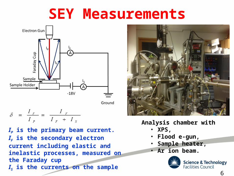
SEY Measurements
IP is the primary beam current.IF is the secondary electron current including elastic and inelastic processes, measured on the Faraday cupIS is the currents on the sample
6
Analysis chamber with• XPS, • Flood e-gun, • Sample heater, • Ar ion beam.
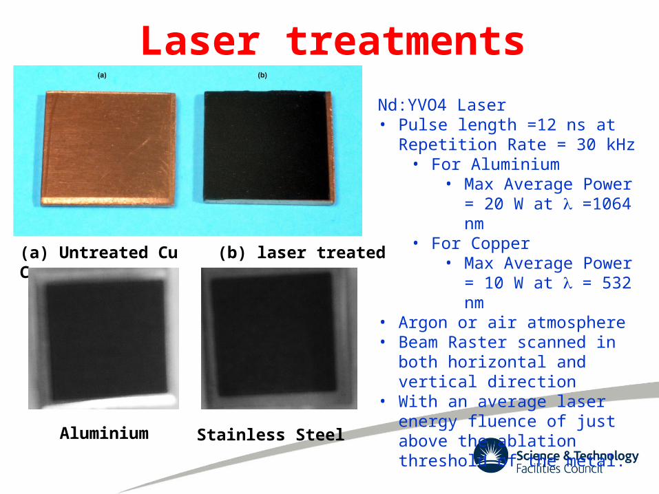
Laser treatments
(a) Untreated Cu (b) laser treated Cu
Aluminium Stainless Steel
Nd:YVO4 Laser• Pulse length =12 ns at Repetition
Rate = 30 kHz• For Aluminium
• Max Average Power = 20 W at =1064 nm
• For Copper• Max Average Power =
10 W at = 532 nm• Argon or air atmosphere• Beam Raster scanned in both
horizontal and vertical direction• With an average laser energy
fluence of just above the ablation threshold of the metal.
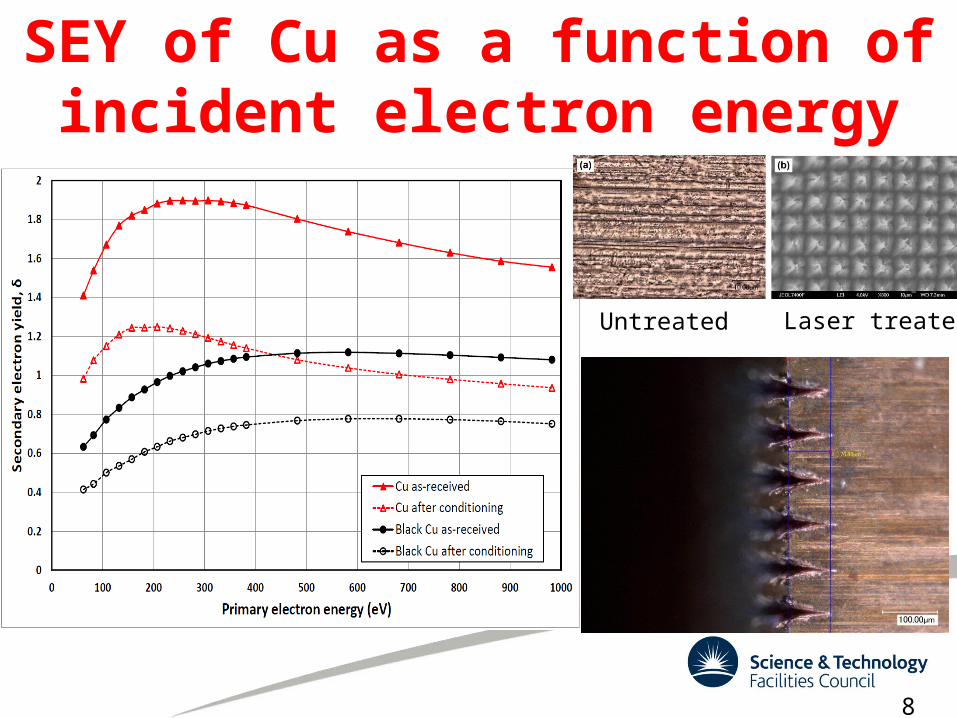
SEY of Cu as a function of incident electron energy
Untreated Laser treated
8
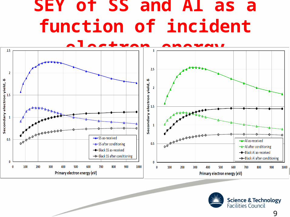
SEY of SS and Al as a function of incident electron energy
9

δmax as a function of electron dose for Al, 306L SS and Cu
Sample
Initial After conditioning to
Qmax
δmax Ema
x (eV
)
δmax Emax (eV)
Qmax (Cmm-
2)
Black Cu
1.12 600 0.78 600 3.510-3
Black SS
1.12 900 0.76 900 1.710-2
Black Al
1.45 900 0.76 600 2.010-2
Cu 1.90 300 1.25 200 1.010-2
SS 2.25 300 1.22 200 1.710-2
Al 2.55 300 1.34 200 1.510-2
10
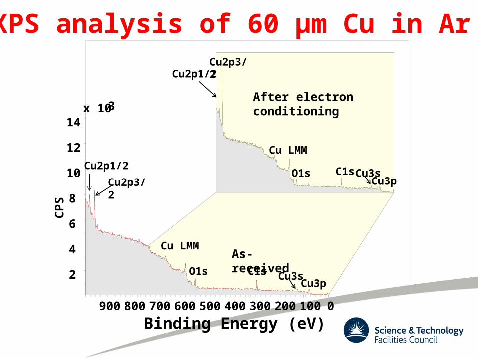
900 800 700 600 500 400 300 200 100 0
Binding Energy (eV)
x 103
2
4
6
8
10
12
14
CP
S
Cu2p1/2
Cu2p3/2
Cu LMM
O1sCu3p
Cu3sC1s
As-received
Cu2p1/2Cu2p3/2
After electron conditioning
Cu LMM
O1s C1sCu3sCu3p
XPS analysis of 60 µm Cu in Ar
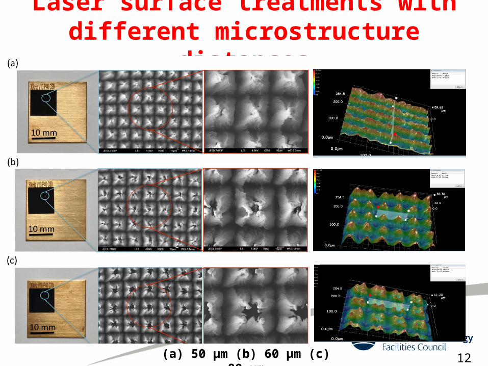
Laser surface treatments with different microstructure distances
12(a) 50 µm (b) 60 µm (c) 80 µm
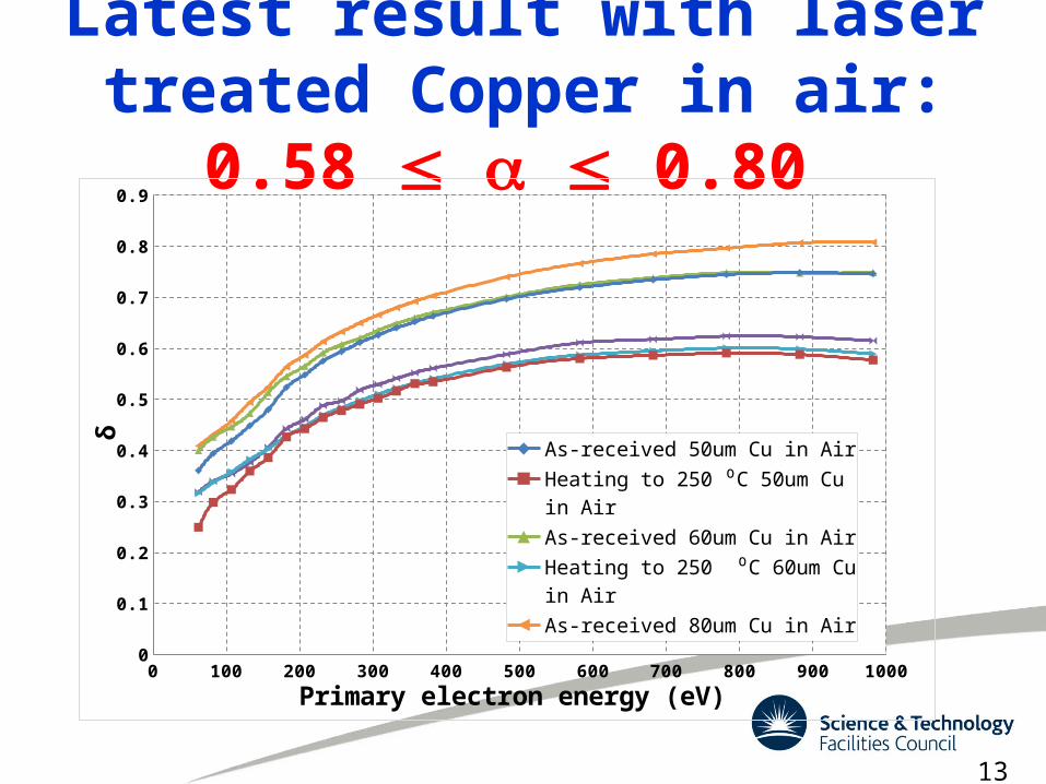
Latest result with laser treated Copper in air: 0.58 0.80
0 100 200 300 400 500 600 700 800 900 10000
0.1
0.2
0.3
0.4
0.5
0.6
0.7
0.8
0.9
As-received 50um Cu in Air
Heating to 250 ⁰C 50um Cu in Air
As-received 60um Cu in Air
Heating to 250 ⁰C 60um Cu in Air
As-received 80um Cu in Air
Heating to 250 ⁰C 80um Cu in Air
Primary electron energy (eV)
δ
13
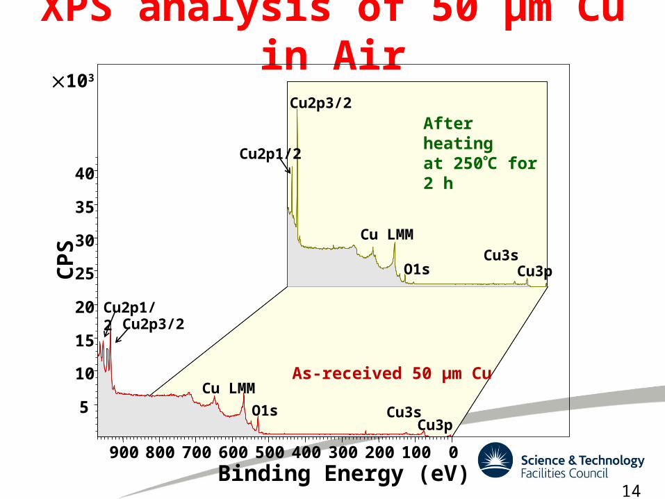
XPS analysis of 50 µm Cu in Air
900 800 700 600 500 400 300 200 100 0Binding Energy (eV)
5
10
15
20
25
30
35
40
CPS
Cu2p3/2
Cu2p1/2
O1sCu3s
Cu3p
Cu LMM
Cu2p3/2Cu2p1/2
Cu LMM
O1s Cu3sCu3p
As-received 50 µm Cu
14
After heating at 250C for 2 h
103
Summary• Laser treatment of the metal surface is a very viable
solution for reducing the SEY < 1.• (a) low cost (process is carried out in an inert gas
environment at atmospheric pressure)• (b) no new material introduced (this is a surface re-
shaping process)• (c) the surface is highly reproducible• (d) the surface is robust and is immune to any surface
delamination (unlike thin film coating).
15
Acknowledgements
People who support me with my PhD
• Reza Valizadeh• Oleg B. Malyshev• Neil Pashley• Elaine A. Seddon• Adrian Hannah
• Svetlana. A. Zotlovskaya• W. Allan Guillespy• Amin Abdolvand
• Mike D. Cropper

Thank for your attention!