low pin count usb development kit user's guide - digi-key sheets/microchip pdfs/low pin... ·...
TRANSCRIPT

© 2009 Microchip Technology Inc. DS41356B
Low Pin Count USBDevelopment Kit
User’s Guide

Note the following details of the code protection feature on Microchip devices:• Microchip products meet the specification contained in their particular Microchip Data Sheet.
• Microchip believes that its family of products is one of the most secure families of its kind on the market today, when used in the intended manner and under normal conditions.
• There are dishonest and possibly illegal methods used to breach the code protection feature. All of these methods, to our knowledge, require using the Microchip products in a manner outside the operating specifications contained in Microchip’s Data Sheets. Most likely, the person doing so is engaged in theft of intellectual property.
• Microchip is willing to work with the customer who is concerned about the integrity of their code.
• Neither Microchip nor any other semiconductor manufacturer can guarantee the security of their code. Code protection does not mean that we are guaranteeing the product as “unbreakable.”
Code protection is constantly evolving. We at Microchip are committed to continuously improving the code protection features of ourproducts. Attempts to break Microchip’s code protection feature may be a violation of the Digital Millennium Copyright Act. If such actsallow unauthorized access to your software or other copyrighted work, you may have a right to sue for relief under that Act.
Information contained in this publication regarding deviceapplications and the like is provided only for your convenienceand may be superseded by updates. It is your responsibility toensure that your application meets with your specifications.MICROCHIP MAKES NO REPRESENTATIONS ORWARRANTIES OF ANY KIND WHETHER EXPRESS ORIMPLIED, WRITTEN OR ORAL, STATUTORY OROTHERWISE, RELATED TO THE INFORMATION,INCLUDING BUT NOT LIMITED TO ITS CONDITION,QUALITY, PERFORMANCE, MERCHANTABILITY ORFITNESS FOR PURPOSE. Microchip disclaims all liabilityarising from this information and its use. Use of Microchipdevices in life support and/or safety applications is entirely atthe buyer’s risk, and the buyer agrees to defend, indemnify andhold harmless Microchip from any and all damages, claims,suits, or expenses resulting from such use. No licenses areconveyed, implicitly or otherwise, under any Microchipintellectual property rights.
DS41356B-page ii
Trademarks
The Microchip name and logo, the Microchip logo, Accuron, dsPIC, KEELOQ, KEELOQ logo, MPLAB, PIC, PICmicro, PICSTART, rfPIC, SmartShunt and UNI/O are registered trademarks of Microchip Technology Incorporated in the U.S.A. and other countries.
FilterLab, Linear Active Thermistor, MXDEV, MXLAB, SEEVAL, SmartSensor and The Embedded Control Solutions Company are registered trademarks of Microchip Technology Incorporated in the U.S.A.
Analog-for-the-Digital Age, Application Maestro, CodeGuard, dsPICDEM, dsPICDEM.net, dsPICworks, dsSPEAK, ECAN, ECONOMONITOR, FanSense, In-Circuit Serial Programming, ICSP, ICEPIC, Mindi, MiWi, MPASM, MPLAB Certified logo, MPLIB, MPLINK, mTouch, PICkit, PICDEM, PICDEM.net, PICtail, PIC32 logo, PowerCal, PowerInfo, PowerMate, PowerTool, REAL ICE, rfLAB, Select Mode, Total Endurance, WiperLock and ZENA are trademarks of Microchip Technology Incorporated in the U.S.A. and other countries.
SQTP is a service mark of Microchip Technology Incorporated in the U.S.A.
All other trademarks mentioned herein are property of their respective companies.
© 2009, Microchip Technology Incorporated, Printed in the U.S.A., All Rights Reserved.
Printed on recycled paper.
© 2009 Microchip Technology Inc.
Microchip received ISO/TS-16949:2002 certification for its worldwide headquarters, design and wafer fabrication facilities in Chandler and Tempe, Arizona; Gresham, Oregon and design centers in California and India. The Company’s quality system processes and procedures are for its PIC® MCUs and dsPIC® DSCs, KEELOQ® code hopping devices, Serial EEPROMs, microperipherals, nonvolatile memory and analog products. In addition, Microchip’s quality system for the design and manufacture of development systems is ISO 9001:2000 certified.

LOW PIN COUNT USBDEVELOPMENT KIT
USER’S GUIDETable of Contents
Preface ........................................................................................................................... 1Introduction......................................................................................................... 1Document Layout................................................................................................ 1Conventions Used in this Guide ......................................................................... 2Recommended Reading ..................................................................................... 3The Microchip Web Site...................................................................................... 3Customer Support............................................................................................... 4Document Revision History ................................................................................ 4
Chapter 1: Overview Introduction .......................................................................................................... 5 Highlights ............................................................................................................. 5 Low Pin Count USB Development Kit Contents .................................................. 5 Low Pin Count USB Development Board Construction and Layout .................... 6 PIC18F14K50 ICD Debug Header ...................................................................... 7 “Getting Started with Microchip’s Low Pin Count USB Solutions” Self-Directed
Course ...................................................................................................... 7 Introduction .......................................................................................................... 9 Prerequisites ....................................................................................................... 9 Resources Required to Complete Project Labs .................................................. 9
Chapter 2: Getting Started Project Labs Project Lab 1 (Enumeration) ............................................................................. 10
2.4.1 Purpose ......................................................................................... 102.4.2 Procedure ...................................................................................... 10Testing The Application .......................................................................... 17
Project Lab 2 (HID Mouse) ................................................................................ 182.5.1 Purpose ......................................................................................... 182.5.2 Overview of the HID Mouse Firmware ........................................... 192.5.3 Procedure ...................................................................................... 20Testing the Application ........................................................................... 21
Project Lab 3 (HID Keyboard) ........................................................................... 222.6.1 Overview of the HID Keyboard Firmware ...................................... 222.6.2 Procedure ...................................................................................... 24Testing the Application ........................................................................... 27
© 2009 Microchip Technology Inc. DS41356B-page iii

Low Pin Count USB Development Kit User’s Guide
Project Lab 4 (CDC – Serial Emulator) ............................................................. 282.7.1 Overview of the CDC – Serial Emulator Firmware ........................ 292.7.2 Procedure ...................................................................................... 31Installing Application Drivers .................................................................. 37Establish Communication ....................................................................... 40Testing the Application ........................................................................... 42
Worldwide Sales and Service .....................................................................................50
DS41356B-page iv © 2009 Microchip Technology Inc.
LOW PIN COUNT USBDEVELOPMENT KIT
USER’S GUIDE
Preface
INTRODUCTIONThis chapter contains general information that will be useful to know before using the Low Pin Count USB Development Kit. Items discussed in this chapter include:• Document Layout• Conventions Used in this Guide• Recommended Reading• The Microchip Web Site• Customer Support• Document Revision History
DOCUMENT LAYOUTThis document describes how to use the Low Pin Count USB Development Kit as a development tool to emulate and debug firmware on a target board. The manual layout is as follows:• Chapter 1. “Overview”• Chapter 2. “Getting Started Project Labs”• Appendix A. “Schematics”
NOTICE TO CUSTOMERS
All documentation becomes dated, and this manual is no exception. Microchip tools and documentation are constantly evolving to meet customer needs, so some actual dialogs and/or tool descriptions may differ from those in this document. Please refer to our web site (www.microchip.com) to obtain the latest documentation available.
Documents are identified with a “DS” number. This number is located on the bottom of each page, in front of the page number. The numbering convention for the DS number is “DSXXXXXA”, where “XXXXX” is the document number and “A” is the revision level of the document.
For the most up-to-date information on development tools, see the MPLAB® IDE on-line help. Select the Help menu, and then Topics to open a list of available on-line help files.
© 2009 Microchip Technology Inc. DS41356B-page 1

Low Pin Count USB Development Kit User’s Guide
CONVENTIONS USED IN THIS GUIDEThis manual uses the following documentation conventions:
DOCUMENTATION CONVENTIONSDescription Represents Examples
Arial font:Italic characters Referenced books MPLAB® IDE User’s Guide
Emphasized text ...is the only compiler...Initial caps A window the Output window
A dialog the Settings dialogA menu selection select Enable Programmer
Quotes A field name in a window or dialog
“Save project before build”
Underlined, italic text with right angle bracket
A menu path File>Save
Bold characters A dialog button Click OKA tab Click the Power tab
N‘Rnnnn A number in verilog format, where N is the total number of digits, R is the radix and n is a digit.
4‘b0010, 2‘hF1
Text in angle brackets < > A key on the keyboard Press <Enter>, <F1>Courier New font:Plain Courier New Sample source code #define START
Filenames autoexec.bat
File paths c:\mcc18\h
Keywords _asm, _endasm, static
Command-line options -Opa+, -Opa-
Bit values 0, 1
Constants 0xFF, ‘A’
Italic Courier New A variable argument file.o, where file can be any valid filename
Square brackets [ ] Optional arguments mcc18 [options] file [options]
Curly brackets and pipe character: { | }
Choice of mutually exclusive arguments; an OR selection
errorlevel {0|1}
Ellipses... Replaces repeated text var_name [, var_name...]
Represents code supplied by user
void main (void){ ...}
DS41356B-page 2 © 2009 Microchip Technology Inc.

Preface
RECOMMENDED READINGThis user’s guide describes how to use the Low Pin Count USB Development Kit. Other useful documents are listed below. The following Microchip documents are available and recommended as supplemental reference resources.Readme FilesFor the latest information on using other tools, read the tool-specific Readme files in the Readmes subdirectory of the MPLAB® IDE installation directory. The Readme files contain update information and known issues that may not be included in this user’s guide.Design CenterMicrochip has a USB design center which can be found on www.microchip.com/usb.The following Microchip Application Notes are available and recommended as supplemental reference resources.
THE MICROCHIP WEB SITEMicrochip provides online support via our web site at www.microchip.com. This web site is used as a means to make files and information easily available to customers. Accessible by using your favorite Internet browser, the web site contains the following information:• Product Support – Data sheets and errata, application notes and sample
programs, design resources, user’s guides and hardware support documents, latest software releases and archived software
• General Technical Support – Frequently Asked Questions (FAQs), technical support requests, online discussion groups, Microchip consultant program member listing
• Business of Microchip – Product selector and ordering guides, latest Microchip press releases, listing of seminars and events, listings of Microchip sales offices, distributors and factory representatives
© 2009 Microchip Technology Inc. DS41356B-page 3

Low Pin Count USB Development Kit User’s Guide
CUSTOMER SUPPORTUsers of Microchip products can receive assistance through several channels:• Distributor or Representative• Local Sales Office• Field Application Engineer (FAE)• Technical SupportCustomers should contact their distributor, representative or field application engineer (FAE) for support. Local sales offices are also available to help customers. A listing of sales offices and locations is included in the back of this document.Technical support is available through the web site at: http://support.microchip.com
DOCUMENT REVISION HISTORY
Revision A (September 2008)• Initial Release of this Document.
Revision B (February 2009)• Corrected document errors
DS41356B-page 4 © 2009 Microchip Technology Inc.

LOW PIN COUNT USBDEVELOPMENT KIT
USER’S GUIDE
Chapter 1. Overview
1.1 INTRODUCTIONThe Low Pin Count USB Development Kit provides an easy, low cost way to evaluate the functionality of Microchip’s PIC18F14K50 and PIC18F13K50 20-pin USB micro-controllers. The all-inclusive kit contains the hardware, software, and code examples necessary to bring your next USB design from concept to first prototype. Created with the USB novice in mind, the kit includes “Getting Started with Microchip’s Low Pin Count USB Solutions”, a self-directed course and lab material designed to ease the learning curve associated with adding USB connectivity to embedded systems.
1.2 HIGHLIGHTSThis chapter discusses:• Low Pin Count USB Development kit contents• Low Pin Count USB Development Board construction and layout
1.3 LOW PIN COUNT USB DEVELOPMENT KIT CONTENTSThe Low Pin Count USB Development Kit contains the following:• (1) fully populated Low Pin Count USB Development Board• (1) unpopulated spare development board• (1) PIC18F14K50 ICD populated expansion header• (1) CD containing the user guide, course materials and product documentation. • (1) PICkit™ 2 Debugger/Programmer with cable.
FIGURE 1-1: LOW PIN COUNT USB DEVELOPMENT KIT
© 2009 Microchip Technology Inc. DS41356B-page 5

Low Pin Count USB Development Kit User’s Guide
1.4 LOW PIN COUNT USB DEVELOPMENT BOARD CONSTRUCTION AND LAYOUT
The Low Pin Count USB Development Board and populated components are shown in Figure 1-2.
FIGURE 1-2: LOW PIN COUNT USB DEVELOPMENT BOARD
1. USB mini-B connector2. J9 regulated 5V connection header3. J14 connects either VBUS (Provided by USB) or J9 regulated 5V to PIC18F14K50
VDD supply4. PICkit™ 2 Debugger/Programmer connection header5. LEDs connected to PORTC (RC0, RC1, RC2, RC3)6. PICkit™ Serial Analyzer connection header7. MAX3232 RS-232 line driver/receiver8. RS-232 connector9. Area provided for user PID/VID information10. Potentiometer11. J12 connects/disconnects VUSB on PIC18F14K5012. Push button13. 12 MHz crystal14. PIC18F14K50 MCU15. Prototyping area16. PICtail™ daughter board expansion header17. SSOP Expansion
1
4 3
10
2 5 6
7 8
9
11 12 13 14 15
16
17
Note: J2-J5, J7, J8 are shunted on the bottom side of the board and thus the functions default connected even though no jumper is installed. Cut the jumper to disable the circuitry attached to each pin.
DS41356B-page 6 © 2009 Microchip Technology Inc.

1.5 PIC18F14K50 ICD DEBUG HEADERThe Low Pin Count USB Development Kit includes a debug header populated with a PIC18F14K50 ICD MCU to enable for use with the PICkit™ 2 debugger/programmer.
FIGURE 1-3: PIC18F14K50 POPULATED MPLAB ICD 2 DEBUG HEADER
To use the debug header, simply remove the PIC18F14K50 mounted in the MCU socket (U2) on the Low Pin Count USB Development Board. Using a pin header (not included), connect the debug header into the MCU socket and connect the PICkit™ 2 programmer/debugger to the provided connection header.
1.6 “GETTING STARTED WITH MICROCHIP’S LOW PIN COUNT USB SOLUTIONS” SELF-DIRECTED COURSE
The Low Pin Count USB Development Kit includes the self-directed course “Getting Started with Microchip’s Low Pin Count USB Solutions”. This course provides an introductory overview to the USB 2.0 protocol and implementation on the PIC18F14K50 MCU. Microchip’s USB Device Firmware Framework is introduced as a resource providing a library of firmware code for USB operation that handles “low-level” tasks and a number of reference projects. The user is guided through a number of “hands-on” labs to reinforce covered concepts.
© 2009 Microchip Technology Inc. DS41356B-page 7
Low Pin Count USB Development Kit User’s Guide
NOTES:
DS41356B-page 8 © 2009 Microchip Technology Inc.

LOW PIN COUNT USBDEVELOPMENT KIT
USER’S GUIDE
Chapter 2. Getting Started Project Labs
2.1 INTRODUCTIONThis section of the user’s guide will walk the user through a number of project labs that will ease the development of original USB design applications. Labs are formatted so that the user is guided through each project’s source code to uncomment or copy and paste sections of code. This format was chosen to force the developer to explore sig-nificant sections of the Framework and familiarize themselves with the overall structure of the source files presented.Lab files can be located in the folder C:\LPCUSBDK_Labs\Labx_files. Each lab folder will contain both the source files for the labs and a folder containing the solutions with working code.Four labs are presented:1. Project Lab 1 (Enumeration): This lab introduces the user to developing unique
descriptors in their own applications that will be used by the Host (PC) to enumerate and ultimately configure the PIC18F14K50.
2. Project Lab 2 (HID Mouse): This lab expands on concepts learned in Project Lab 1 using the descriptors defined. The user will walk through the development of application specific functions within the mouse.c firmware file. The end applica-tion will behave like a Human Interface Device Class (HID) mouse by moving the pointer on the PC screen.
3. Project Lab 3 (HID Keyboard): In this lab the user is required to alter the descrip-tors to implement a HID keyboard-based application. The potentiometer on the Low Pin Count USB Development Board is rotated to change the HID specifica-tion unicode value transmitted through the USB to the PC that will print charac-ters based on an ADC conversion.
4. Project Lab 4 (CDC Serial Emulator): Finally, the user will implement a communication protocol converter using the Communication Device Class (CDC) driver.
2.2 PREREQUISITESThese labs assume that the user:1. Has completed the self-directed course “Getting Started with Microchip’s Low
Pin Count USB Solutions” provided on the accompanying CD.2. Is familiar with the MPLAB IDE and C18 compiler.3. Has some programming experience using the C language.4. Is familiar with Microchip’s PIC18F family of microcontrollers.
2.3 RESOURCES REQUIRED TO COMPLETE PROJECT LABSIn order to complete the Project Labs, the user should have:1. The most current version of the MPLAB IDE and C18 compiler installed on their
PC. The MPLAB IDE can be found at: http://www.microchip.com/stellent/idc-plg?IdcService=SS_GET_PAGE&nodeId=1406&dDoc-Name=en019469&part=SW007002
© 2009 Microchip Technology Inc. DS41356B-page 9

Low Pin Count USB Development Kit User’s Guide
2. The C18 compiler can be found at:http://www.microchip.com/stellent/idcplg?Idc-Service=SS_GET_PAGE&nodeId=1406&dDocName=en010014
3. The most current version of the PICkit 2 programmer software.4. Downloaded and installed the Microchip Full-Speed USB Firmware Framework.
Available free at: http://www.microchip.com/stellent/idcplg?IdcSer-vice=SS_GET_PAGE&nodeId=2651¶m=en534494
5. A copy of the “Microchip USB Device Firmware Framework User’s Guide” (DS51679)
6. A copy of the PIC18F13K50/14K50 data sheet (DS41350)7. A copy of the USB Revision 2.0 Specification available for download from:
http://www.usb.org/developers/docs/This will prove useful as reference throughout the labs.
8. A copy of the Universal Serial Bus (USB) HID Usage Tables available for download at:http://www.usb.org/developers/devclass_docs/Hut1_12.pdf
9. Downloaded the USB HID Descriptor Tool available free at:http://www.usb.org/developers/hidpage/dt2_4.zip
10. A copy of the Universal Serial Bus Class Definitions for Communications Devices document available for download at:http://www.usb.org/developers/devclass_docs
11. Unzipped the LPCUSBDK_Labs.zip file to the C: directory.
2.4 PROJECT LAB 1 (ENUMERATION)
2.4.1 PurposeThe purpose of this lab is intended to introduce the user to creating a project in the MPLAB IDE using Microchip’s Full-Speed USB Firmware Framework. Though many application examples in the Framework can be used to create original code, building the Framework from scratch is a great way to get familiar to the overall functionality of this multitasking tool. The user will create a project, ensure that the IDE is configured accordingly, and alter the usb_descriptor.c file to enable the enumeration of the PIC18F14K50 as a HID mouse device.
2.4.2 Procedure
2.4.2.1 BUILDING THE FRAMEWORK
1. Open the MPLAB IDE by selecting Start>Programs>Microchip>MPLAB IDE vx.xx>MPLAB IDE
2. Once in the MPLAB IDE, start the Project Wizard by selecting Project>Project Wizard
3. Select the PIC18F14K50 as the device, select the MPLAB C18 C Compiler as the language toolsuite, and create a new project folder in the following directory:C:\Microchip Solutions\Project Lab 1\Project Lab 1
Note: In this and all subsequent project labs, the USB cable must be discon-nected from the USB mini-B connector on the Low Pin Count USB Devel-opment Board when programming with the PICkit 2 programmer.
DS41356B-page 10 © 2009 Microchip Technology Inc.

4. In the Add Existing Files to Your Project window, navigate to C:\LPCUSBDK_Labs\Lab1_files and copy the following files:a) enumeration.c
b) usb_descriptors.c
c) HardwareProfile.h
d) usb_config.h
To copy a file, click on the large letter A in front of the file path in the right pane of the window until a large letter C appears. This mode makes a copy of this file into the new project directory leaving the original file intact. (see Figure 2-1)
FIGURE 2-1:
This next section will add the files that will build the Framework that takes care of the low level USB functions. This does not need to be done for every application. The included example projects could be easily converted to suit the needs of a custom application. However, in the interest of providing an intuitive introduction to the Framework, this lab builds this application from scratch.
5. Next, navigate to C:\Microchip Solutions\Microchip\Include and copy over the following files:a) Compiler.h
b) GenericTypeDefs.h
Note: These files are the user files that will need to be changed to implement any application.
Note: These files are used by all the applications in the Framework. Therefore, changing these files will affect all applications. If any of these files are inadvertently altered, it is recommended that the Framework be reinstalled.
© 2009 Microchip Technology Inc. DS41356B-page 11

Low Pin Count USB Development Kit User’s Guide
6. Navigate to C:\Microchip Solutions\Microchip\Include\Usb and copy the following files:a) usb.h
b) usb_ch9.h
c) usb_common.h
d) usb_device.h
e) usb_function_hid.h (file defines components specific to the HID class)f) usb_hal.h
g) usb_hal_pic18.h (file defines components specific to the PIC18 architecture)
7. Next, navigate to C:\Microchip Solutions\Microchip\Usb and copy the following file:a) usb_device.c
8. Next, navigate to C:\Microchip Solutions\Microchip\Usb\HID Device Driver to copy the HID specific source file:a) usb_function_hid.c
9. Finally, navigate to C:\MCC18\lkr and copy the 18f14k50.lkr linker file.10. Click Next>Finish to exit the project wizard. The Project window should now
resemble Figure 2-2.
FIGURE 2-2: PROJECT WINDOW FOR LAB 1
If the project window isn’t open in the MPLAB IDE workspace, select View> Project.Next the MPLAB IDE will need to be configured for the Framework by directing the C18 compiler to the associated file locations. 11. In the MPLAB IDE, select Project>Build Options…>Project. The Build Options
dialog will appear (Figure 2-3).
DS41356B-page 12 © 2009 Microchip Technology Inc.

12. Click on the Directories tab and select Output Directory and click New to add a new path. Click on the button, navigate to C:\LPCUSBDK_Labs\Lab1_files and create a new folder called output. Highlight the folder and click OK. This will now be the folder where the output files are placed.
13. Within the “Show directories for” drop-down menu, select the “Include Search Path” directory. Ensure that the C:\MCC18\h directory path is listed. Select New and navigate to C:\Microchip Solutions\Microchip\Include and click OK to add to the directory. Repeat these steps to add the application folder C:\LPCUSBDK_Labs\Lab1_files.
14. In the “show directories for:” drop-down menu, select Library Search Path. Ensure that the C:\MCC18\lib is listed. Next, select the Linker-Script Path and ensure that the path points to C:\MCC18\lkr directory.
FIGURE 2-3: CONFIGURING FOR MICROCHIP USB FIRMWARE FRAMEWORK
15. Click Apply, followed by OK to apply these settings and close the Build Options window.
At this point, Framework has been built.
DEFINING PROJECT DESCRIPTORS
Double click the enumeration.c source file in the project window to open. Scroll down to the ProcessIO(). Note it is empty. Therefore, this application will do noth-ing. The intention of this lab is to introduce the user to properly configure the firmware so that the PIC18F14K50 will enumerate as a HID mouse once connected to the Host PC. Therefore, the usb_descriptors.c file will need to be altered accordingly. As a
© 2009 Microchip Technology Inc. DS41356B-page 13

Low Pin Count USB Development Kit User’s Guide
reference, the USB Revision 2.0 specification should be opened to Section 9-5 “Descriptors”. This section details the various components required in each type of descriptor (device, configuration, interface etc.). This usb_descriptor.c file should be an exact replica of the source file of the same name found in the Framework folder C:\Microchip Solutions\USB Device - HID - Mouse\HID - Mouse – Firmware\usb_descriptor.c
This file can be used as a reference during debugging.16. In the MPLAB IDE Project window, select and open the usb_descriptors.c
source file.Note #include "./USB/usb_function_hid.h" at the top of the file. If a different class of device is being defined for a given application, the appropriate class header file will need to be included here.
17. Scroll down to the device descriptor section and copy and paste the code in Example 2-1 between the curly brackets in the section labeled:
//ADD DEVICE DESCRIPTOR CODE HERE
EXAMPLE 2-1: DEVICE DESCRIPTOR FOR LAB 1
18. Scroll down to the configuration, class specific and interface descriptor section. Copy and paste the code in Example 2-2 between the brackets between the curly brackets in the section labeled:
//ADD CONFIGURATION, CLASS SPECIFIC AND//INTERFACE DESCRIPTOR CODE HERE
Note: The user may wish to clean up the look of the code by spacing comment sections accordingly. Tabs were ignored to ensure completeness for this document.
0x12, // Size of this descriptor in bytesUSB_DESCRIPTOR_DEVICE, // DEVICE descriptor type0x0110, // USB Spec Release Number in BCD format0x00, // Class Code0x00, // Subclass code0x00, // Protocol codeUSB_EP0_BUFF_SIZE, // Max packet size for EP0, see
// usbcfg.hMY_VID, // Vendor IDMY_PID, // Product ID0x0003, // Device release number in BCD format0x01, // Manufacturer string index0x02, // Product string index0x00, // Device serial number string index0x01 // Number of possible configurations
DS41356B-page 14 © 2009 Microchip Technology Inc.

EXAMPLE 2-2: CONFIGURATION, CLASS SPECIFIC AND INTERFACE
The user is encouraged to take some time and compare the code in the preceding code examples against the descriptor definitions in the USB Revision 2.0 specification Section 9-5 “Descriptors”. Comments have been included to make the code intuitive and easier to reference with the USB specification. Definition sources can be located by highlighting the definition name and selecting Edit>Find in Files in the MPLAB IDE. This will locate all instances of the definition within the project and list them in the Output window.
0x09,//sizeof(USB_CFG_DSC), // Size of this descriptor in bytesUSB_DESCRIPTOR_CONFIGURATION, // CONFIGURATION descriptor typeDESC_CONFIG_WORD(0x0022), // Total length of data for this cfg1, // Number of interfaces in this cfg1, // Index value of this configuration0, // Configuration string index_DEFAULT|_SELF, // Attributes, see usbd.h50, // Max power consumption (2X mA)
/* Interface Descriptor */0x09,//sizeof(USB_INTF_DSC), // Size of this descriptor
// in bytesUSB_DESCRIPTOR_INTERFACE, // INTERFACE descriptor type0, // Interface Number0, // Alternate Setting Number1, // Number of endpoints in this intfHID_INTF, // Class codeBOOT_INTF_SUBCLASS, // Subclass codeHID_PROTOCOL_MOUSE, // Protocol code0, // Interface string index
/* HID Class-Specific Descriptor */0x09,//sizeof(USB_HID_DSC)+3, // Size of this descriptor in bytes DSC_HID, // HID descriptor typeDESC_CONFIG_WORD(0x0111), // HID Spec Release Number in BCD
// format(1.11)0x00, // Country Code (0x00 for Not
// supported)HID_NUM_OF_DSC, // Number of class descriptors, see
// usbcfg.hDSC_RPT, // Report descriptor typeDESC_CONFIG_WORD(50), // sizeof(hid_rpt01),
// Size of the report descriptor/* Endpoint Descriptor */0x07,/*sizeof(USB_EP_DSC)*/USB_DESCRIPTOR_ENDPOINT, // Endpoint DescriptorHID_EP | _EP_IN, // EndpointAddress_INT, // AttributesDESC_CONFIG_WORD(3), // size0x01 // Interval
© 2009 Microchip Technology Inc. DS41356B-page 15

Low Pin Count USB Development Kit User’s Guide
19. Scroll down to the string descriptor section. String descriptors can be used to describe a device for the user. At enumeration, the string descriptor will appear at the lower right hand section of the screen notifying the user of the intended purpose of the device. Copy and paste the code between the curly brackets for both the manufacturer string descriptor and product string descriptor in Example 2-3 and Example 2-4 in the sections labeled:
//ADD MANUFACTURER STRING DESCRIPTOR CODE HERE
and
//ADD PRODUCT STRING DESCRIPTOR CODE HERE
EXAMPLE 2-3: MANUFACTURER STRING DESCRIPTOR FOR LAB 1
EXAMPLE 2-4: PRODUCT STRING DESCRIPTOR FOR LAB 1
Finally, the last descriptor to be added is the report descriptor. Early in the development of the HID class specification, subclasses were intended to be used to identify different HID device categories. However, it became clear that due to the diverse variety of devices that could be imple-mented in this class, a more robust definition method was required. Therefore, this class does not use subclasses to define most protocols. Instead, a mecha-nism called the report descriptor identifies data protocol and the types of data provided for a device. It is here that such things as the number of buttons on a mouse, the unicode key value ranges for a keyboard, and other such characteristics are defined.The USB organization has provided a number of documents and tools specifically designed to implement the report descriptor that can be accessed at:http://www.usb.org/developers/hidpage/The user is encouraged to download the HID Usage Tables that define a report descriptor for a given device. Also, the USB organization has further developed a HID Descriptor Tool that will assist the developer in designing their own report descriptors. The tool also includes predefined descriptors for commonly used HID devices such as a mouse and keyboard. This document and tool can be found at the links listed in Section 2.3 “Resources Required to Complete Project Labs”.
20. Scroll down to the report descriptor section and copy and paste the code in Example 2-5 between the curly brackets in the section labeled:
//ADD REPORT DESCRIPTOR CODE HERE
'M','i','c','r','o','c','h','i','p',' ','T','e','c','h','n','o','l','o','g','y',' ','I','n','c','.'
'M','o','u','s','e',' ','E','n','u','m','e','r','a','t','i','o','n ', ' ','D','e','m','o'
DS41356B-page 16 © 2009 Microchip Technology Inc.

EXAMPLE 2-5: REPORT DESCRIPTOR FOR LAB 1
The descriptor definitions are now complete.21. Compile the project. There should be no errors.
Testing The Application22. Configure the Low Pin Count USB Development Board so that the J14 jumper is
on the two right-most pins. This application will use power supplied by VBUS off of the USB cable.
23. Disconnect the J12 jumper.24. Connect the PICkit 2 programmer to the PC USB port and then to the J6
connector on the Low Pin Count USB Development Board.25. Open the PICkit 2 programmer environment by selecting Start>Programs>Micro-
chip PICkit 2 vx.xx.26. The PICkit 2 programmer software should recognize that the PICkit 2 is
connected and identify the PIC18F14K50 device.27. Within the PICkit 2 programmer software, navigate to the
C:\LPCUSBDK_Labs\Lab1_files\output folder and download the Project Lab 1.hex file to the PIC18F14K50.
28. Disconnect the PICkit 2 programmer from J6 and plug the USB cable into the mini B connector, J1.Once connected, the enumeration process should begin. The Host PC should recognize the connection of a new device and display a notification at the right corner of the screen indicating the “Mouse Enumeration Demo” text placed in the product string earlier in this lab.
0x05, 0x01, /* Usage Page (Generic Desktop)*/
0x09, 0x02, /* Usage (Mouse)*/
0xA1, 0x01, /* Collection (Application)*/
0x09, 0x01, /* Usage (Pointer)*/
0xA1, 0x00, /* Collection (Physical)*/
0x05, 0x09, /* Usage Page (Buttons) */
0x19, 0x01, /* Usage Minimum (01)*/
0x29, 0x03, /* Usage Maximum (03)*/
0x15, 0x00, /* Logical Minimum (0)*/
0x25, 0x01, /* Logical Maximum (0)*/
0x95, 0x03, /* Report Count (3)*/
0x75, 0x01, /* Report Size (1)*/
0x81, 0x02, /* Input (Data, Variable, Absolute)*/
0x95, 0x01, /* Report Count (1)*/
0x75, 0x05, /* Report Size (5)*/
0x81, 0x01, /* Input (Constant) ;5 bit padding */
0x05, 0x01, /* Usage Page (Generic Desktop)*/
0x09, 0x30, /* Usage (X)*/
0x09, 0x31, /* Usage (Y)*/
0x15, 0x81, /* Logical Minimum (-127)*/
0x25, 0x7F, /* Logical Maximum (127)*/
0x75, 0x08, /* Report Size (8)*/
0x95, 0x02, /* Report Count (2)*/
0x81, 0x06, /* Input (Data, Variable, Relative)*/
0xC0, 0xC0
© 2009 Microchip Technology Inc. DS41356B-page 17

Low Pin Count USB Development Kit User’s Guide
29. Next, the device driver will be checked on the Host PC.Navigate to Device Manager on the Host PC by selecting Start>Settings>Control Panel>System to open the System Properties window. Select the Hardware tab and click the Device Manager button.
30. In the Device Manager window, expand the Human Interface Devices. Right click on each driver and select Properties until the “Mouse Enumeration Demo” driver is located. See Figure 2-4.
EXAMPLE 2-6: DEVICE MANAGER WINDOW AND HID DRIVERS INSTALLED
The user is encouraged to familiarize themselves with the HID Usage Tables and HID Descriptor Tool. Changing various aspects of the descriptors and then repeating the enumeration lab steps will help build on these concepts.
2.5 PROJECT LAB 2 (HID MOUSE)
2.5.1 PurposeThis lab implements the Low Pin Count USB Demo Board in a HID mouse application that moves the mouse pointer on the Host PC in a circle.
C:\Microchip Solutions\USB Device - HID - Mouse\HID - Mouse – Firmware
The user is encouraged to use these files as a reference when needed.
Note: The source code developed here is an exact replica of the USB Device - HID – Mouse application found in the Framework.
DS41356B-page 18 © 2009 Microchip Technology Inc.

2.5.2 Overview of the HID Mouse FirmwareAs with most of the Framework applications, the user defined source code is called from the ProcessIO() function in the <application>.c file. The user defined firm-ware will manipulate the Host PC mouse pointer to move in a single direction for 14 times through the main loop. After 14 times, the mouse pointer changes direction ulti-mately moving in a complete circle. A bit flag is initialized named emulate_mode that will toggle HIGH/LOW whenever the push button on the Low Pin Count USB Develop-ment Board is pressed. The status of this flag will start or stop pointer movement on the screen by not calling the user defined function, emulate_mouse(), which handles the mouse movement routines.The flowchart for the user defined function is shown in Figure 2-4.
FIGURE 2-4: FLOWCHART FOR THE EMULATE_MOUSE()
In the flowchart of Figure 2-4, it can be seen that if the emulate_mode flag is ‘0’, the directional data transmitted along the USB is cleared. Note that data is transmitted from the PIC18F14K50 whether or not the flag is set. Data is transmitted only when the SIE is capable of transmitting it. This check is implemented in code by using the if(HIDTxHandleBusy(lastTransmission) == 0) conditional statement. The lastTransmission is loaded at the time of transmission and processed by the HIDTxHandleBusy macro in the conditional ‘if’ statement.If the emulate_mode flag is set, the function enters into the mouse pointer movement algorithm. This is accomplished by keeping track of a counter variable, movement_length. When this variable exceeds 14, a buffer array is loaded with new directional data as supplied by the dir_table array defined at the top of the mouse.c file. Each element of the array is accessed by incrementing the vector variable counter. The buffer array is then loaded into a hid_report_in[] buffer array that is used by the HIDTxPacket macro to transmit the data along the USB to the Host PC.
Emulate_Mouse ()
emulate_mode = TRUE
YES YES
movement_length > 14?
Change directional data to next vector
Clear directional data Keep directional data as before
NONO
NOPIC18F14K50 own the SIE
YESTransmit directional
data along USBreturn return
TRUE = 1FALSE = 0
© 2009 Microchip Technology Inc. DS41356B-page 19
Low Pin Count USB Development Kit User’s Guide
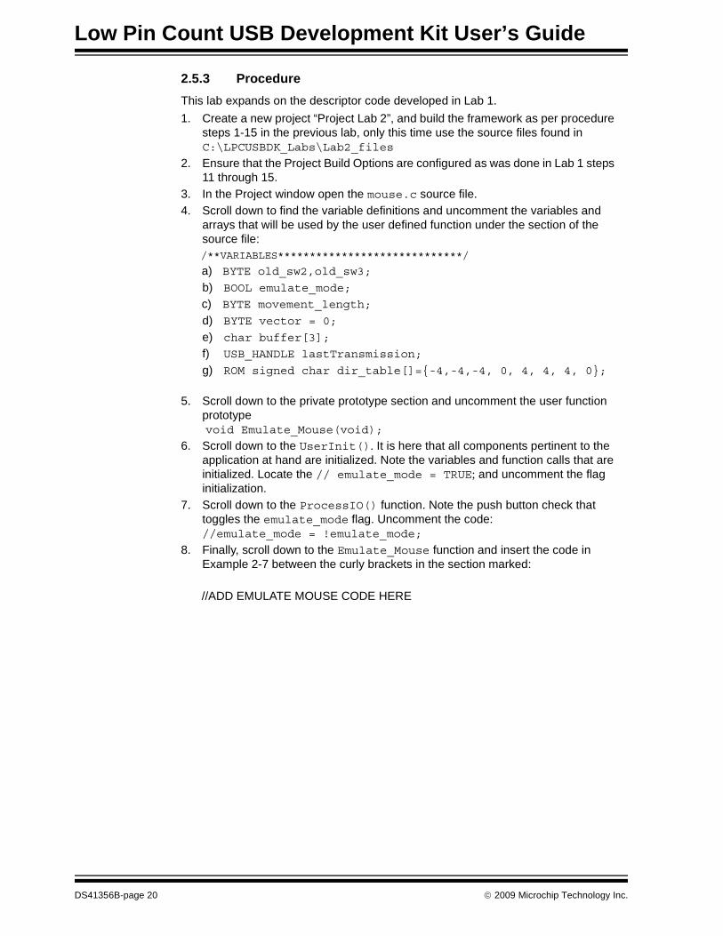
2.5.3 ProcedureThis lab expands on the descriptor code developed in Lab 1.1. Create a new project “Project Lab 2”, and build the framework as per procedure
steps 1-15 in the previous lab, only this time use the source files found inC:\LPCUSBDK_Labs\Lab2_files
2. Ensure that the Project Build Options are configured as was done in Lab 1 steps 11 through 15.
3. In the Project window open the mouse.c source file.4. Scroll down to find the variable definitions and uncomment the variables and
arrays that will be used by the user defined function under the section of the source file:/**VARIABLES*****************************/
a) BYTE old_sw2,old_sw3;
b) BOOL emulate_mode;
c) BYTE movement_length;
d) BYTE vector = 0;
e) char buffer[3];
f) USB_HANDLE lastTransmission;
g) ROM signed char dir_table[]={-4,-4,-4, 0, 4, 4, 4, 0};
5. Scroll down to the private prototype section and uncomment the user function prototype void Emulate_Mouse(void);
6. Scroll down to the UserInit(). It is here that all components pertinent to the application at hand are initialized. Note the variables and function calls that are initialized. Locate the // emulate_mode = TRUE; and uncomment the flag initialization.
7. Scroll down to the ProcessIO() function. Note the push button check that toggles the emulate_mode flag. Uncomment the code://emulate_mode = !emulate_mode;
8. Finally, scroll down to the Emulate_Mouse function and insert the code in Example 2-7 between the curly brackets in the section marked:
//ADD EMULATE MOUSE CODE HERE
DS41356B-page 20 © 2009 Microchip Technology Inc.
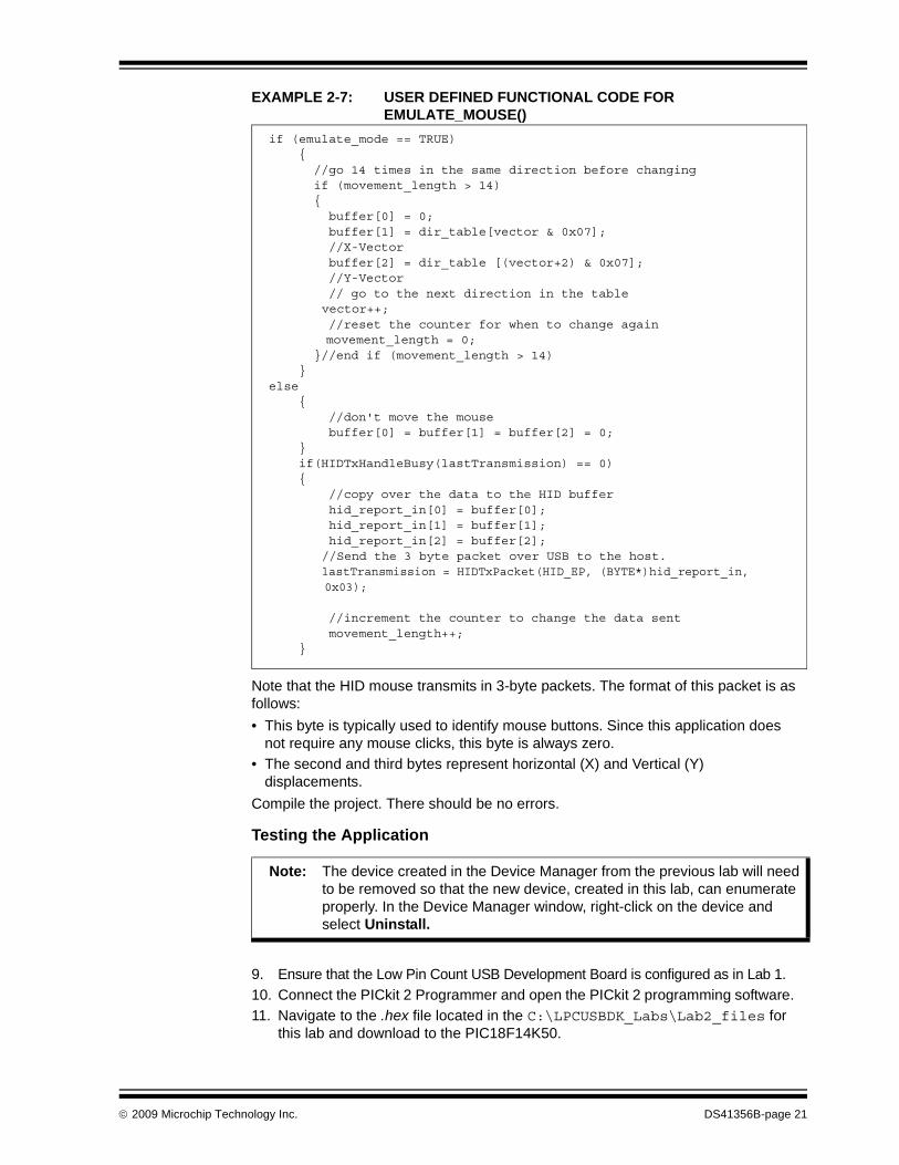
EXAMPLE 2-7: USER DEFINED FUNCTIONAL CODE FOR EMULATE_MOUSE()
Note that the HID mouse transmits in 3-byte packets. The format of this packet is as follows:• This byte is typically used to identify mouse buttons. Since this application does
not require any mouse clicks, this byte is always zero.• The second and third bytes represent horizontal (X) and Vertical (Y)
displacements.Compile the project. There should be no errors.
Testing the Application
9. Ensure that the Low Pin Count USB Development Board is configured as in Lab 1.10. Connect the PICkit 2 Programmer and open the PICkit 2 programming software.11. Navigate to the .hex file located in the C:\LPCUSBDK_Labs\Lab2_files for
this lab and download to the PIC18F14K50.
if (emulate_mode == TRUE) { //go 14 times in the same direction before changing if (movement_length > 14) { buffer[0] = 0; buffer[1] = dir_table[vector & 0x07]; //X-Vector buffer[2] = dir_table [(vector+2) & 0x07]; //Y-Vector // go to the next direction in the table
vector++; //reset the counter for when to change again
movement_length = 0; }//end if (movement_length > 14) }else { //don't move the mouse buffer[0] = buffer[1] = buffer[2] = 0; } if(HIDTxHandleBusy(lastTransmission) == 0) { //copy over the data to the HID buffer hid_report_in[0] = buffer[0]; hid_report_in[1] = buffer[1]; hid_report_in[2] = buffer[2]; //Send the 3 byte packet over USB to the host. lastTransmission = HIDTxPacket(HID_EP, (BYTE*)hid_report_in,
0x03);
//increment the counter to change the data sent movement_length++; }
Note: The device created in the Device Manager from the previous lab will need to be removed so that the new device, created in this lab, can enumerate properly. In the Device Manager window, right-click on the device and select Uninstall.
© 2009 Microchip Technology Inc. DS41356B-page 21

Low Pin Count USB Development Kit User’s Guide
12. Disconnect the PICkit 2 and connect the Low Pin Count USB Demo Board to the Host PC port.
13. The device should enumerate and the LEDs on the board flash in accordance with the BlinkUSBStatus() discussed in the self-directed course.
14. Pressing the push button should start and subsequently stop the mouse pointer moving in a circle on the Host PC screen.
The user is encouraged to experiment with this application by altering the length of time that the mouse pointer moves until a directional change or altering the values in the ROM signed char dir_table[]={-4,-4,-4, 0, 4, 4, 4, 0};
2.6 PROJECT LAB 3 (HID KEYBOARD)CAUTION
In this lab, the PIC18F14K50 is implemented as a HID keyboard device. The ADC peripheral is configured to perform conversions on the voltage level present on the port pin connected to the potentiometer on the Low Pin Count USB Development Board. The value in the ADC result register is then used to create a numeric value between 4 and 29 that will display an alphabetic character between ‘a’ and ‘z’ on the Host PC screen (refer to HID Usage Tables document Section 10 “Keyboard/Keypad Page” (0x07)). As the potentiometer is rotated, the character outputted to the screen will change accordingly. The user should note that this application could be applied to a data logger application with the potentiometer on the Low Pin Count USB Development Board simulating a mixed signal interface to monitor an off-chip application. The data generated and transmitted via the USB could be connected and interpreted by a Graphical User Interface on the Host PC to monitor real-time application behavior or used to store essential data for later analysis.
2.6.1 Overview of the HID Keyboard FirmwareThe keyboard()is the user-defined function that is called from ProcessIO() to parse the data received from the ADC module, transmit the numeric value along the USB and display the appropriate character on the screen. This function is implemented as a state machine. The state diagram for this function is shown in Figure 2-5.
CAUTION
A word of caution, this HID device has the potential to be harmful if a key combination is used that initiates a Windows® shortcut. Great care should be taken to ensure that the transmitting buffer contains only keycodes that the user is confident will not produce any harmful key combinations.
DS41356B-page 22 © 2009 Microchip Technology Inc.

FIGURE 2-5: STATE DIAGRAM FOR KEYBOARD()
Referring to the state diagram, the individual states perform these general tasks:1. STATE 0: this is a delay state used to ensure that the hold capacitor on the ADC
peripheral has sufficient time to charge before a conversion is initiated.
2. STATE 1: this state begins the conversion process by setting the GO_DONE bit in the ADCON0 control register.
3. STATE 2: checks for a completed conversion (GO_DONE = 0) before allowing the state machine to move to the next state.
4. STATE 3: this final state reads the ADC result register, converts the result to a value between 4 (‘a’) and 29 (‘z’), loads a HID buffer and transmits the resulting data along the USB to the Host PC for output to an opened .txt document.
The main point the user should take away from this lab is this: since the USB Frame-work is a multitasking environment, no blocking code should be used. Therefore, as shown in this lab, state machines will become the norm in many applications. The keyboard() state machine is called each time through the main loop. If the condition that changes the current state to the next state is not met, the state machine simply returns from the function without changing states. The next time through the main loop, the condition is once again checked. If the state condition has been met, the state is changed to the next sequential state. The state variable is declared as a type static as this will allow the current value in the state variable to remain after a return from the keyboard().
STATE0
STATE1
STATE2
STATE3
delaycounter < 9000
delaycounter > 9000
Start ADC Conversion(Set the GO_DONE bit
While GO_DONE = 1(ADC Conversion in Progress)
GO_DONE = 0 (Cleared in Hardware)
• Read ADC result register• Load HID buffer• Transmit HID buffer contents along USB
© 2009 Microchip Technology Inc. DS41356B-page 23
Low Pin Count USB Development Kit User’s Guide
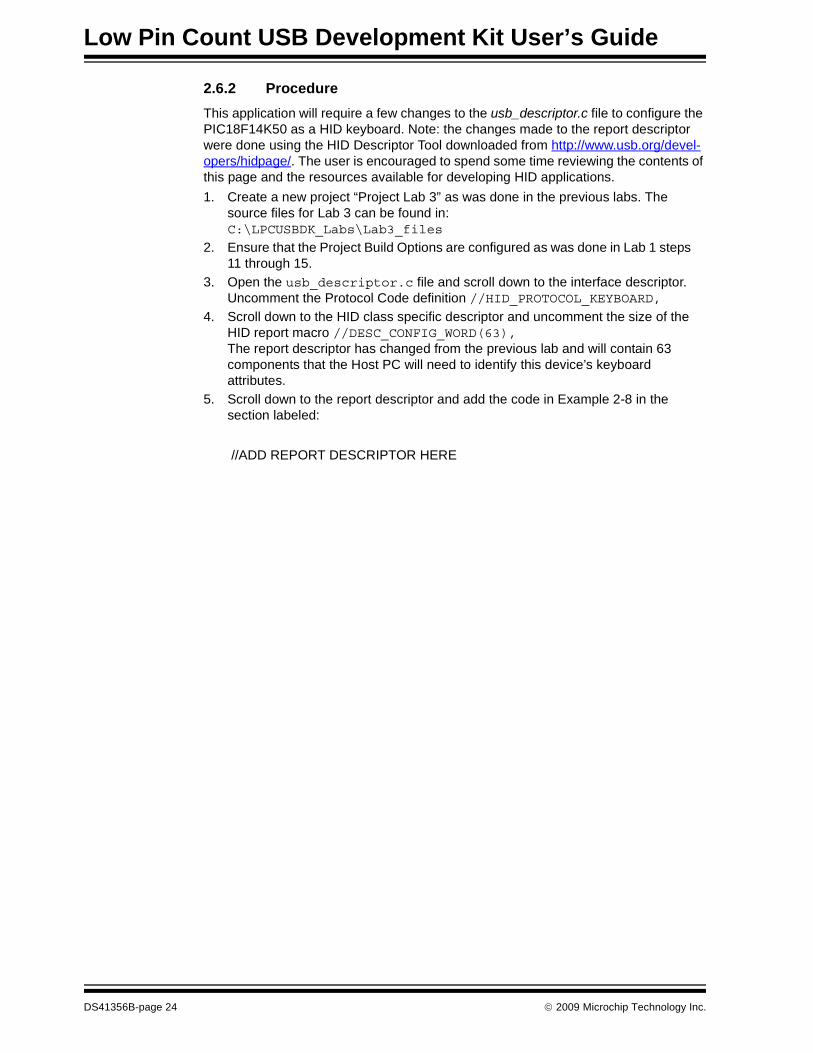
2.6.2 ProcedureThis application will require a few changes to the usb_descriptor.c file to configure the PIC18F14K50 as a HID keyboard. Note: the changes made to the report descriptor were done using the HID Descriptor Tool downloaded from http://www.usb.org/devel-opers/hidpage/. The user is encouraged to spend some time reviewing the contents of this page and the resources available for developing HID applications.1. Create a new project “Project Lab 3” as was done in the previous labs. The
source files for Lab 3 can be found in:C:\LPCUSBDK_Labs\Lab3_files
2. Ensure that the Project Build Options are configured as was done in Lab 1 steps 11 through 15.
3. Open the usb_descriptor.c file and scroll down to the interface descriptor. Uncomment the Protocol Code definition //HID_PROTOCOL_KEYBOARD,
4. Scroll down to the HID class specific descriptor and uncomment the size of the HID report macro //DESC_CONFIG_WORD(63), The report descriptor has changed from the previous lab and will contain 63 components that the Host PC will need to identify this device’s keyboard attributes.
5. Scroll down to the report descriptor and add the code in Example 2-8 in the section labeled:
//ADD REPORT DESCRIPTOR HERE
DS41356B-page 24 © 2009 Microchip Technology Inc.

EXAMPLE 2-8: REPORT DESCRIPTOR FOR KEYBOARD()
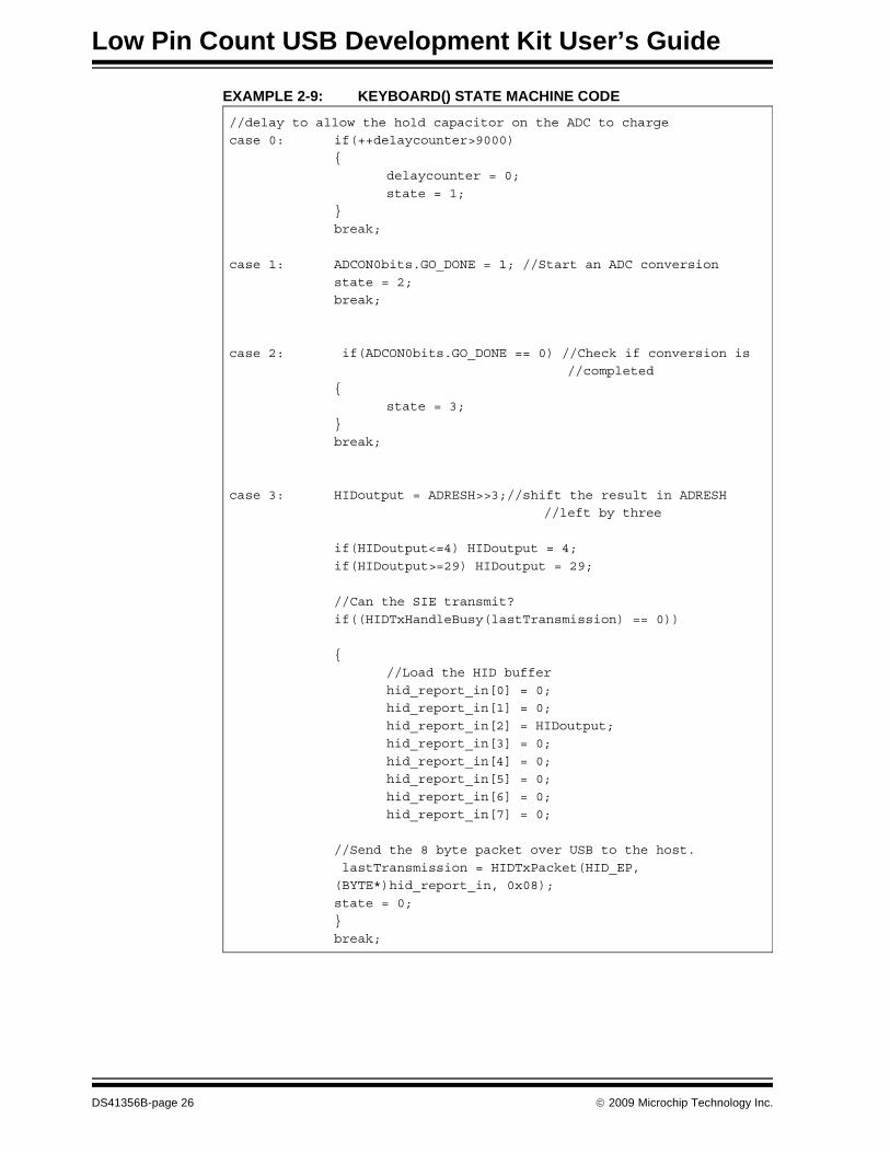
Next, the keyboard.c source file will be configured.6. In the Project window, open the keyboard.c source file and scroll down to the
UserInit(). Uncomment the port and ADC initialization code. The user is urged to review the PIC18F14K50 data sheet as to the significance of these initializations for the appropriate peripheral. // ADCON0=0x29;// ADCON1 = 0X00;// ADCON2=0x3F; Scroll down to the keyboard() and copy and paste the code in Example 2-9 between the curly braces in the switch at:
//ADD STATE MACHINE CODE HERE
0x05, 0x01, // USAGE_PAGE (Generic Desktop)
0x09, 0x06, // USAGE (Keyboard)
0xa1, 0x01, // COLLECTION (Application)
0x05, 0x07, // USAGE_PAGE (Keyboard)
0x19, 0xe0, // USAGE_MINIMUM (Keyboard LeftControl)
0x29, 0xe7, // USAGE_MAXIMUM (Keyboard Right GUI)
0x15, 0x00, // LOGICAL_MINIMUM (0)
0x25, 0x01, // LOGICAL_MAXIMUM (1)
0x75, 0x01, // REPORT_SIZE (1)
0x95, 0x08, // REPORT_COUNT (8)
0x81, 0x02, // INPUT (Data,Var,Abs)
0x95, 0x01, // REPORT_COUNT (1)
0x75, 0x08, // REPORT_SIZE (8)
0x81, 0x03, // INPUT (Cnst,Var,Abs)
0x95, 0x05, // REPORT_COUNT (5)
0x75, 0x01, // REPORT_SIZE (1)
0x05, 0x08, // USAGE_PAGE (LEDs)
0x19, 0x01, // USAGE_MINIMUM (Num Lock)
0x29, 0x05, // USAGE_MAXIMUM (Kana)
0x91, 0x02, // OUTPUT (Data,Var,Abs)
0x95, 0x01, // REPORT_COUNT (1)
0x75, 0x03, // REPORT_SIZE (3)
0x91, 0x03, // OUTPUT (Cnst,Var,Abs)
0x95, 0x06, // REPORT_COUNT (6)
0x75, 0x08, // REPORT_SIZE (8)
0x15, 0x00, // LOGICAL_MINIMUM (0)
0x25, 0x65, // LOGICAL_MAXIMUM (101)
0x05, 0x07, // USAGE_PAGE (Keyboard)
0x19, 0x00, // USAGE_MINIMUM (Reserved (no event indicated))
0x29, 0x65, // USAGE_MAXIMUM (Keyboard Application)
0x81, 0x00, // INPUT (Data,Ary,Abs)
0xc0
© 2009 Microchip Technology Inc. DS41356B-page 25
Low Pin Count USB Development Kit User’s Guide
EXAMPLE 2-9: KEYBOARD() STATE MACHINE CODE
//delay to allow the hold capacitor on the ADC to charge
case 0: if(++delaycounter>9000)
{
delaycounter = 0;
state = 1;
}
break;
case 1: ADCON0bits.GO_DONE = 1; //Start an ADC conversion
state = 2;
break;
case 2: if(ADCON0bits.GO_DONE == 0) //Check if conversion is
//completed
{
state = 3;
}
break;
case 3: HIDoutput = ADRESH>>3;//shift the result in ADRESH
//left by three
if(HIDoutput<=4) HIDoutput = 4;
if(HIDoutput>=29) HIDoutput = 29;
//Can the SIE transmit?
if((HIDTxHandleBusy(lastTransmission) == 0))
{
//Load the HID buffer
hid_report_in[0] = 0;
hid_report_in[1] = 0;
hid_report_in[2] = HIDoutput;
hid_report_in[3] = 0;
hid_report_in[4] = 0;
hid_report_in[5] = 0;
hid_report_in[6] = 0;
hid_report_in[7] = 0;
//Send the 8 byte packet over USB to the host.
lastTransmission = HIDTxPacket(HID_EP,
(BYTE*)hid_report_in, 0x08);
state = 0;
}
break;
DS41356B-page 26 © 2009 Microchip Technology Inc.

Note that the HID keyboard transmits in 8-byte packets along the USB. The format of this packet is as follows:• The first byte is used for a modifier such as a shift or ctrl character. (i.e., a
simultaneous shift and character press on the typical keyboard.)• The second byte is reserved.• The remaining bytes are used to carry numeric values that contain the desired
keyboard characters pressed.Compile the project. There should be no errors.
Testing the Application7. Connect the PICkit 2 Programmer and open the PICkit 2 programming software8. Navigate to the .hex file for this lab and download to the PIC18F14K50.9. Disconnect the PICkit 2. Open a new notepad, word document or other text editor
program and click inside the document to place the cursor.10. Connect the Low Pin Count USB Demo Board to the Host PC port. The device
should enumerate as “Keyboard Demo”.11. Within the selected text editor, a series of character entries should appear. 12. Turn the potentiometer on the Low Pin Count USB Demo Board to change the
character on the screen.The user is encouraged to experiment with this application by referring to the Keyboard Usage Page and changing the keyboard packet transmitted in the state machine.
© 2009 Microchip Technology Inc. DS41356B-page 27

Low Pin Count USB Development Kit User’s Guide
2.7 PROJECT LAB 4 (CDC – SERIAL EMULATOR)In this lab, the PIC18F14K50 is used as a serial emulator taking an RS-232 data trans-mission using the Enhanced Universal Asynchronous Synchronous Receiver Transmit-ter (EUSART) peripheral and converting it to the USB protocol within firmware. Many embedded applications continue to use the RS-232 interface to communicate with external systems. However, as USB becomes more prevalent, RS-232 ports are disap-pearing from newer PC’s. A simple solution is to emulate RS-232 over the USB. In this example, a virtual COM port is created that will allow the USB connection to appear as an RS-232 COM connection. Furthermore, this example makes use of Windows drivers that already exist eliminating the need to alter existing software such as the Hyper Terminal application.The RS-232 connector on the Low Pin Count USB Development Board is configured so that the PIC18F14K50 can be used as a Data Terminal Equipment (DTE) device to interface with Data Communications Equipment (DCE) devices such as alarm systems, modems etc. To accommodate this lab and eliminate the need for the user to create their own DCE interface circuitry, a Null-Modem Gender Changer has been provided in the kit to crosslink the transmit and receive lines so that the Low Pin Count USB Devel-opment Board can be converted from a DTE device to a DCE device. In this way, the main concepts of serial emulation can be delivered using only two Hyperlink Terminals on a single PC with one RS-232 serial COM port and one USB connection.
Microchip’s Full-Speed USB Firmware Framework provides information files (.inf) for all of its CDC application examples that automate Windows driver alterations freeing the user from doing this manually. Once the PIC18F14K50 has been programmed and then connected to the PC USB port, Windows “New Hardware Found Wizard” will prompt the user for additional driver information. At this point, the user need only direct Windows to the directory containing the appropriate .inf file.
Microchip’s Full-Speed USB Firmware Framework provides all the source code necessary to perform low-level RS-232 functions, thereby abstracting this from the user.
NOTICE
Kits shipped with the RS-232 pin corrector (p/n 04-02087R1) do not require the Null Modem Gender Changer but will instead require a female/female gender changer that does not cross-link the transmit and receive lines. The pin corrector is not used in this lab as the RS-232 con-nector on this version of the Low Pin Count USB Development Board is configured as a DCE device. Applications using the Low Pin Count USB Development Board as a DTE device will require the use of the pin corrector.
Note: The only information that is required by the user in the .inf is the Vendor Identification (VID) and Product Identification (PID) numbers specific to their original design.
DS41356B-page 28 © 2009 Microchip Technology Inc.

2.7.1 Overview of the CDC – Serial Emulator FirmwareThe CDC Serial Emulator firmware flow is shown in Figure 2-6.
FIGURE 2-6: FLOWCHART FOR CDC SERIAL EMULATOR CODE
RS232 OUT Buffer available
andUSB OUT Buffer NOT EMPTY
YES
YESCopy USB OUT Buffer to RS232 OUT Buffer
Copy next byte to EUSART
Copy USB IN Buffer toUSB Buffer
Add byte to RS232 IN Buffer
RS232 OUT Buffer NOT EMPTYand
EUSART is EMPTY
EUSART hasa byte
YES
YESRS232 IN Buffer
has data and USB IN Buffer available
CDCTxService( )
ProcessIO( )
NO
NO
NO
NO
© 2009 Microchip Technology Inc. DS41356B-page 29

Low Pin Count USB Development Kit User’s Guide
Referring to the flowchart in Figure 2-6, the firmware located in the ProcessIO() first checks if the previous RS-232 transmission has been sent via the USB using the RS232_Out_Data_Rdy flag. If this flag is cleared (indicating previous transmission has been sent), firmware then checks if any new data has been sent from the RS-232 connection and is ready to be transmitted via the USB using the getsUSBUSART(). This function copies data into a buffer and returns the number of bytes the buffer con-tains. The function ensures that only the expected numbers of bytes, in this case 64, are actually copied into this buffer. Also, if there is no data available, the function returns a zero value indicating no data is available. In this way the function does not wait for data and is therefore, non-blocking, keeping in mind that all firmware must conform to this multitasking environment. Following the RS-232 data check, the firmware then checks if the EUSART transmit register, TXREG, is empty. This is accomplished using the mTxRdyUSART() macro, which checks the TRMT bit in the TXSTA (Transmit Status Control) register in the EUSART peripheral. If the TRMT bit is cleared, the TXREG is Full, and Empty if the TRMT bit is set. Note that this bit is automatically set following a successful transmis-sion from the TXREG. If set, the data collected into the buffer by the getsUSBUSART() is then transferred into the TXREG one byte at a time each time through the main loop. Again, such macros take care of the low-level RS-232 communication in a non-blocking fashion so the user doesn’t have to. If the TXREG isn’t empty, then the previous data has not been transmitted via the USB and should not be overwritten.The firmware next checks to see if the CDC class device is ready to transmit data. This is accomplished by using the mUSBUSARTIsTxrfReady() flag. The user must ensure that this flag is set to ‘1’ before calling the putUSBUSART() function. As a safety pre-caution, this function checks the state one more time to make sure it does not override any pending transactions. This function writes data to the USB. The CDCTxSevice() services the transfer of data to the host. This function keeps track of a state machine and breaks up long strings of data into multiple USB data pack-ets. It is called once each time through the main program loop. The state machine for the CDCTxService() is shown in Figure 2-7 and the source code can be found in the usb_function_cdc.c source file. The reader is encouraged to reference this firmware and compare it against the state diagram at their leisure.
DS41356B-page 30 © 2009 Microchip Technology Inc.

FIGURE 2-7: CDCTXSERVICE( ) STATE DIAGRAM
2.7.2 ProcedureThis application requires significant changes to the usb_descriptor.c file to configure the PIC18F14K50 as a CDC device. Note the absence of the report descriptor. The user is encouraged to spend some time reviewing the usb_descriptor.c file and com-pare it against the information found in the Universal Serial Bus Class Definitions for Communications Devices document referenced at the beginning of this chapter. Note that this lab applies the same firmware found in the CDC – Serial Emulator application example in Microchip’s Full-Speed USB Firmware Framework application examples and can be used as a reference for this lab.1. Create a new project for lab 4, using the Project Wizard, called “Project Lab 4”
as was done in the previous labs. The only files added, at this point, will be the usb_descriptor.c and main.c source files, as well as a new unique descrip-tor for Lab 4 rm18f14k50.lkr can be found in:C:\LPCUSBDK_Labs\Lab4_files
Step through to close the Project Wizard. This time, the project will be set up to resemble the application examples in the Framework using sub-folders to distin-guish and organize the different source files in the Project window. All remaining source/header files will be added from the Project window.
2. Right click on the Source Files folder in the Project window and select Create Subfolder...
CDC_TX_READY CDC_TX_BUSY
CDC_TX_COMPLETING CDC_TX_BUSY_ZLP
cdc_tx_lenl=0
cdc_tx_len==0CDC_BULK_BD_IN.Cnt <Max EP Size
cdc_tx_len==0CDC_BULK_BD_IN.Cnt <Max EP Size
mCDCUsartTxlsBusy()==0
CDC_BULK_BD_IN.Cnt==0
© 2009 Microchip Technology Inc. DS41356B-page 31

Low Pin Count USB Development Kit User’s Guide
FIGURE 2-8: CREATING A SUB-FOLDER IN THE PROJECT WINDOW
Name the new folder “USB Stack” and click OK. 3. Right click on this new USB Stack folder and select Add Files. In the Add Files
to Project window, navigate to C:\Microchip Solutions\Microchip\Usb and select the usb_device.c source file. Ensure that “System: File(s) are External to Project, Use Absolute Path” is selected then click Open.
FIGURE 2-9: ADDING THE USB_DEVICE.C FILE TO THE USB STACK FOLDER
This should add the usb_device.c to the “USB Stack” folder in the Project window.
DS41356B-page 32 © 2009 Microchip Technology Inc.

Repeat this step to add the usb_function_cdc.c file from the C:\Microchip Solutions\Microchip\USB\CDC Device Driver directory to the same “USB Stack” folder.4. In the Project window create two new sub-folders under the Header Files folder
called “Common” and “USB Stack” as per step 2 of this lab.5. Right click on the “USB Stack” folder and add the following files from the
C:\Microchip Solutions\Microchip\Include\Usb directory as was done in step 3 of this lab:• usb.h
• usb_ch9.h
• usb_common.h
• usb_device.h
• usb_function_cdc.h
• usb_hal.h
• usb_hal_pic18.h
6. Right click on the “Common” folder and add the following files from the C:\Microchip Solutions\Microchip\Include directory as was done in step 3 of this lab:• Compiler.h
• GenericTypeDefs.h
7. Ensure that the Project Build Options are configured as was done in Lab 1 steps 11 through 15.
8. Compile the project. There should be no errors.The Project window should now resemble Figure 2-10.
© 2009 Microchip Technology Inc. DS41356B-page 33

Low Pin Count USB Development Kit User’s Guide
FIGURE 2-10: PROJECT WINDOW FOR LAB 4
9. Next, the EUSART peripheral will need to be initialized to enable asynchronous communication with a baud rate of 19200. To do this, open the main.c file and scroll down to the InitializeUSART(). This function is called by the UserInit(). Note that in this function, code has been formatted to allow configuration dependant on the specific device and compiler used. Copy and paste the contents of Example 2-10 into the section of the Initialize-USART() function labeled:
//ADD C18 PIC18F14K50 EUSART INITIALIZATION CODE HERE
DS41356B-page 34 © 2009 Microchip Technology Inc.

EXAMPLE 2-10: INITIALIZEUSART() CODE
The reader is encouraged to review the data sheet for the PIC18F14K50 EUSART section for more information on the specifics of the configuration code.Next, the application specific code will be added that will implement the flowchart shown in Figure 2-6.10. Scroll down to the ProcessIO()and copy and paste the contents of
Example 2-11 into the section labeled:/*****************************************************ADD CODE TO CHECK IF RS232 HASBEEN SENT ALONG USBAND THE CODE TO CHECK IF ANY NEW RS232 TRANSMISSION HAS BEEN RECEIVED AND STORED******************************************************/
As per the flowchart in Figure 2-6, this code will ensure that the buffer containing the data transmitted from the RS-232 has been sent to the USB firmware. If so, the code then checks for any new RS-232 data that has been stored in the buffer.
#if defined(__18CXX)unsigned char c;
#if defined(__18F14K50)
ANSELHbits.ANS11 = 0; // Make RB5 digital so USART can
//use pin for Rx
#endif
UART_TRISRx=1; // RX
UART_TRISTx=0; // TX
TXSTA = 0x24; // TX enable BRGH=1
RCSTA = 0x90; // Single Character RX
SPBRG = 0x70;
SPBRGH = 0x02; // 0x0271 for 48MHz -> 19200 baud
BAUDCON = 0x08; // BRG16 = 1
c = RCREG; // read
#endif
© 2009 Microchip Technology Inc. DS41356B-page 35

Low Pin Count USB Development Kit User’s Guide
EXAMPLE 2-11: RS-232 BUFFER CHECK
11. Next, the code that will check and then load the EUSART Transmit shift register (TXREG) with the contents of the RS-232 buffer will be entered. Copy and paste the contents of Example 2-12 into the section labeled:/*******************************************************ADD THE CODE THAT WILL CHECK IF THE EUSART TXREG IS EMPTY.IF SO, BEGIN SENDING DATA FROM RS232 TRANSMISSION INTOTHE TXREG ONE BYTE AT A TIME*******************************************************/
EXAMPLE 2-12: TXREG CHECK AND LOAD CODE
12. Finally, the code to check if the CDC class device is ready to send data into the USB transmit buffer will be entered. Copy and paste the contents of code in Example 2-13 into the section labeled:/**********************************************************ADD THE CODE THAT WILL CHECK IF THE CDC CLASS DEVICE IS READY TO LOAD THE USB BUFFER*********************************************************/
// only check for new USB buffer if the old RS232 buffer is
// empty.
// Additional USB packets will be NAK'd
// until the buffer is free.
if (RS232_Out_Data_Rdy == 0)
{
LastRS232Out = getsUSBUSART(RS232_Out_Data,64);
if(LastRS232Out > 0)
{
RS232_Out_Data_Rdy = 1; // signal
//buffer full
RS232cp = 0;// Reset the current position
}
}
if(RS232_Out_Data_Rdy && mTxRdyUSART())
{
putcUSART(RS232_Out_Data[RS232cp]);
++RS232cp;
if (RS232cp == LastRS232Out)
RS232_Out_Data_Rdy = 0;
}
DS41356B-page 36 © 2009 Microchip Technology Inc.

EXAMPLE 2-13: CHECK CDC CLASS DEVICE CODE
13. At this point, all the necessary code to run the CDC – Serial Emulator application is complete. Compile the project. There should be no errors.
Installing Application Drivers14. Connect the PICkit 2 Programmer and open the PICkit 2 programming software.15. Navigate to the .hex file for this lab and download to the PIC18F14K50.16. Disconnect the PICkit 2. 17. Connect the Low Pin Count USB Demo Board to the Host PC port. Windows
should recognize the PIC18F14K50 as “CDC RS-232 Emulation Demo”.
Windows will now prompt the user for driver information.
18. In the “Welcome to the Found New Hardware Wizard” window, select “No, not this time” and then Next (see Figure 2-11).
FIGURE 2-11: FOUND NEW HARDWARE WIZARD WINDOW
if((mUSBUSARTIsTxTrfReady()) && (NextUSBOut > 0))
{
putUSBUSART(&USB_Out_Buffer[0], NextUSBOut);
NextUSBOut = 0;
}
© 2009 Microchip Technology Inc. DS41356B-page 37
Low Pin Count USB Development Kit User’s Guide
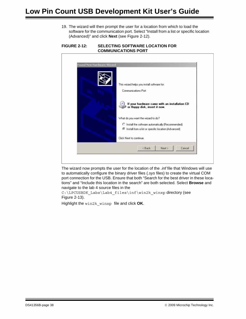
19. The wizard will then prompt the user for a location from which to load the software for the communication port. Select ”Install from a list or specific location (Advanced)” and click Next (see Figure 2-12).
FIGURE 2-12: SELECTING SOFTWARE LOCATION FOR COMMUNICATIONS PORT
The wizard now prompts the user for the location of the .inf file that Windows will use to automatically configure the binary driver files (.sys files) to create the virtual COM port connection for the USB. Ensure that both “Search for the best driver in these loca-tions” and “Include this location in the search” are both selected. Select Browse and navigate to the lab 4 source files in the C:\LPCUSBDK_Labs\Lab4_files\inf\win2k_winxp directory (see Figure 2-13).Highlight the win2k_winxp file and click OK.
DS41356B-page 38 © 2009 Microchip Technology Inc.

FIGURE 2-13: DIRECTING WINDOWS TO THE .INF FILE FOR THE CDC – SERIAL EMULATOR APPLICATION
Click Next. The window should now begin loading the software. If any warnings are issued, select Continue Anyway.20. The wizard should indicate that the software for the Communications port was
successfully installed. Select Finish. (See Figure 2-14.)
FIGURE 2-14: SUCCESSFUL SOFTWARE INSTALLATION WINDOW
© 2009 Microchip Technology Inc. DS41356B-page 39

Low Pin Count USB Development Kit User’s Guide
Next, the virtual COM port will be checked in the Device Manager to identify the COM port number.
Establish Communication21. Using step 29 in Project Lab 1 to navigate to the Device Manager, expand the
ports (COM and LPT). The new virtual COM port (usually COM 5 and above on most PCs) created by the .inf file should be found in the Ports (COM & LPT) drop-down list in the Device Manager window. If there is difficulty locating the vir-tual COM port, right click on each driver and select Properties until the CDC RS-232 Emulation Demo is located. Note the COM port number for both the vir-tual COM port and the COM port used for an RS-232 connection (Serial Port Connection on the Host PC). Figure 2-15 shows a list of COM ports available. The reader’s list may differ.
FIGURE 2-15: EXAMPLE LIST OF AVAILABLE COM PORTS IN THE DEVICE MANAGER
This COM port number will be used in the Hyper Terminal program to establish connec-tivity to both the USB and RS-232 connections between the Low Pin Count USB Development Board and Host PC.22. Open a Hyper Terminal window by selecting within Windows,
Start>Programs>Accessories>Communications>HyperTerminal. The Hyper Terminal Program should now prompt the user for a “Connection Description”.23. Name this first connection “USB Connection” and click OK. (See Figure 2-16.)
DS41356B-page 40 © 2009 Microchip Technology Inc.
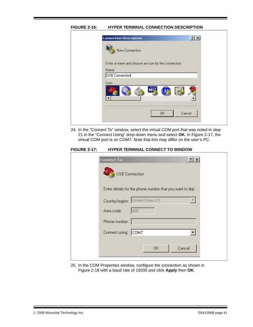
FIGURE 2-16: HYPER TERMINAL CONNECTION DESCRIPTION
24. In the “Connect To“ window, select the virtual COM port that was noted in step 21 in the “Connect Using” drop-down menu and select OK. In Figure 2-17, the virtual COM port is on COM7. Note that this may differ on the user’s PC.
FIGURE 2-17: HYPER TERMINAL CONNECT TO WINDOW
25. In the COM Properties window, configure the connection as shown in Figure 2-18 with a baud rate of 19200 and click Apply then OK.
© 2009 Microchip Technology Inc. DS41356B-page 41

Low Pin Count USB Development Kit User’s Guide
FIGURE 2-18: HYPER TERMINAL COM PROPERTIES WINDOW
This now establishes a connection between the Low Pin Count USB Development Board USB connector and the Host PC COM port. 26. Next, connect the RS-232 serial cable to the connector on the Low Pin Count
USB Development Board and to a serial port connector on the Host PC using a “Gender Changer” adapter.
27. Repeat steps 22 to 25 to establish an RS-232 connection using the related port noted in step 21 for the Serial Port Connector on the Host PC. Name this con-nection “RS232 Connection” and ensure that the COM properties resemble Figure 2-18.
Testing the Application28. Once connected, click inside the RS232 Connection COM window and type a
message. Note that unless configured to echo locally, the originating message COM window will not print the message. The message should be printed in the “USB Connection” COM window as shown in Figure 2-19.
DS41356B-page 42 © 2009 Microchip Technology Inc.
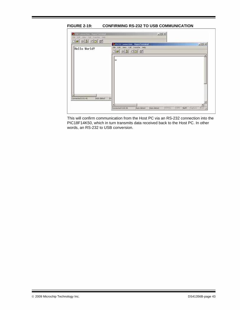
FIGURE 2-19: CONFIRMING RS-232 TO USB COMMUNICATION
This will confirm communication from the Host PC via an RS-232 connection into the PIC18F14K50, which in turn transmits data received back to the Host PC. In other words, an RS-232 to USB conversion.
© 2009 Microchip Technology Inc. DS41356B-page 43

Low Pin Count USB Development Kit User’s Guide
NOTES:
DS41356B-page 44 © 2009 Microchip Technology Inc.
LOW PIN COUNT USBDEVELOPMENT KIT
USER’S GUIDE
Appendix A. Schematics
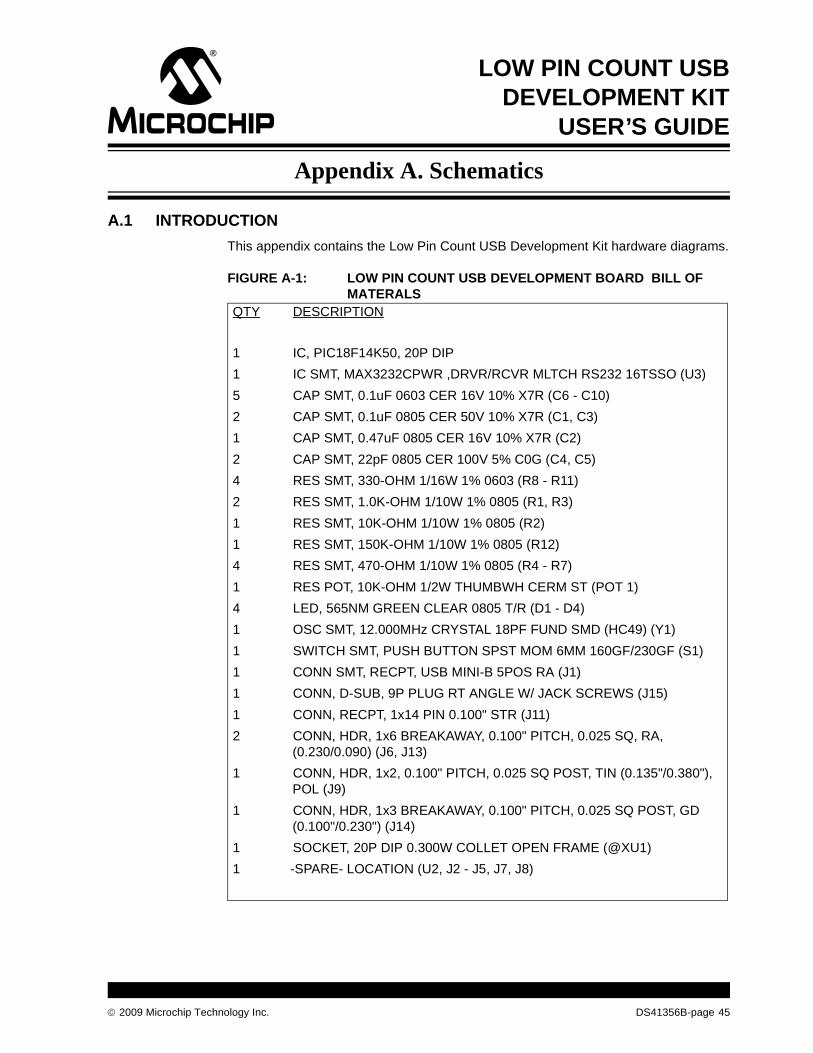
A.1 INTRODUCTIONThis appendix contains the Low Pin Count USB Development Kit hardware diagrams.
FIGURE A-1: LOW PIN COUNT USB DEVELOPMENT BOARD BILL OF MATERALS
QTY DESCRIPTION
1 IC, PIC18F14K50, 20P DIP 1 IC SMT, MAX3232CPWR ,DRVR/RCVR MLTCH RS232 16TSSO (U3)5 CAP SMT, 0.1uF 0603 CER 16V 10% X7R (C6 - C10)2 CAP SMT, 0.1uF 0805 CER 50V 10% X7R (C1, C3)1 CAP SMT, 0.47uF 0805 CER 16V 10% X7R (C2)2 CAP SMT, 22pF 0805 CER 100V 5% C0G (C4, C5)4 RES SMT, 330-OHM 1/16W 1% 0603 (R8 - R11)2 RES SMT, 1.0K-OHM 1/10W 1% 0805 (R1, R3)1 RES SMT, 10K-OHM 1/10W 1% 0805 (R2)1 RES SMT, 150K-OHM 1/10W 1% 0805 (R12)4 RES SMT, 470-OHM 1/10W 1% 0805 (R4 - R7)1 RES POT, 10K-OHM 1/2W THUMBWH CERM ST (POT 1)4 LED, 565NM GREEN CLEAR 0805 T/R (D1 - D4)1 OSC SMT, 12.000MHz CRYSTAL 18PF FUND SMD (HC49) (Y1)1 SWITCH SMT, PUSH BUTTON SPST MOM 6MM 160GF/230GF (S1)1 CONN SMT, RECPT, USB MINI-B 5POS RA (J1)1 CONN, D-SUB, 9P PLUG RT ANGLE W/ JACK SCREWS (J15)1 CONN, RECPT, 1x14 PIN 0.100" STR (J11)2 CONN, HDR, 1x6 BREAKAWAY, 0.100" PITCH, 0.025 SQ, RA,
(0.230/0.090) (J6, J13)1 CONN, HDR, 1x2, 0.100" PITCH, 0.025 SQ POST, TIN (0.135"/0.380"),
POL (J9)1 CONN, HDR, 1x3 BREAKAWAY, 0.100" PITCH, 0.025 SQ POST, GD
(0.100"/0.230") (J14)1 SOCKET, 20P DIP 0.300W COLLET OPEN FRAME (@XU1)1 -SPARE- LOCATION (U2, J2 - J5, J7, J8)
© 2009 Microchip Technology Inc. DS41356B-page 45

Low Pin Count USB Development Kit User’s Guide
A.2 SCHEMATICS
FIGURE A-2: PICkit™ 2 USB DEVELOPMENT SCHEMATIC
MA
X32
3CP
WR
VP
P
VD
D
GN
DIC
SP
DAT
ICS
PC
LKT1
G
J6
PIC
kit™
Ser
ial
J13
330Ω
330Ω
330Ω
330Ω
SW
–B3S
1002
S1
R1
1K
10K
R2
J3+V
J21K
CW
PO
T110
KC
CW
R3
C3
0.1uF
PC
B T
RA
CE
ON
SO
LDE
R S
IDE
Jum
per N
otP
opul
ated
C2
0.47
uF
J12
PIC18F1XK50-I/SS
PIC18F1XX50-I/P
U2
U1
+V
C8
C9
0.1u
F
0.1u
F
R8
R9
R11
R10
U3
+VC
6 C7
0.1u
F0.
1uF
C10 0.
1uF
J15
DE
9P-M
RS
ICS
P1
J14
+V
J9 VIN
3PH
DR
0.1u
FC
1
Y1
12 M
Hz
22pF
C5
C4
22pFP
ICki
t™ 1
HD
R1X
14
J11
PC
B T
RA
CE
ON
SO
LDE
R S
IDE
Jum
per N
otP
opul
ated J4 J5 J7 J8
D1
D2
D3 D4
+V
R12 15
0K
470Ω
470Ω
470Ω
470ΩR4
R5
R6
R7
J11 2 3 4 5
6
1 2 3 4 5 6
1 2 3 4 5
6 7 8 9
16 2 14 7 13 8 6
1 3 4 5 11 10 12 9 15
PIN
1
PIN
2
PIN
3
PIN
4
1
3
4
6
7
2
5
8
9
10
11
12
13
14
1 2 3 4 5 6
2
3
20 19 18 17 16 15 14 13 12 11
1 2 3 4 5 6 7 8 9 10
21
31
2
VB
US
D-
D+ Shi
eld
VD
D
RA
5/O
SC
1/C
KLI
RA
4/A
N3/
OS
C2/
CLK
O
RA
3/M
CLR
/VP
P
RC
5/C
PP
1/P
1A/T
0CK
I
RC
4/P
1B/C
12O
UT/
SR
Q
RC
3/A
N7/
P1C
/C12
IN3-
/PG
M
RC
6/A
N8/
SS
/T13
CK
I/T1O
SC
I
RC
7/A
N9/
SD
O/T
1OS
CO
RB
7/TX
/CK
VS
S
RA
0/D
+/P
GD
RA
1/D
-/PG
C
VU
SB
RC
0/A
N4/
C12
IN+/
INT0
/VR
EF+
RC
1/A
N5/
C12
IN1-
/INT1
/VR
EF-
RC
2/A
N6/
P1D
/C12
IN2-
/CV
RE
F/IN
T2
RB
4/A
N10
/SD
I/SD
A
RB
5/A
N11
/RX
/DT
RB
6/S
CK
/SC
L
VC
CV
+
T1O
UT
T2O
UT
R1I
N
R2I
N
V-
C1+
C1-
C2+
C2-
T1IN
T2IN
R1O
UT
R2O
UT
GN
D
VIN
VB
US
VIN
RA
5
RA
4
RA
3
RC
5
RC
4
RC
3
RC
6
RC
7
RB
7/C
S/T
X
D+/
ICS
PD
AT
D-/I
CS
PC
LK
RC
0
RC
1
RC
2
RB
4/S
DA
/SD
I/RTS
RB
5/S
DO
/RX
RB
6/S
CL/
SC
K/C
TS
RB
4/A
DS
/SD
I/RTS
1
RA
3
RB
7/C
S/T
X
RB
4/S
DA
/SD
I/RTS
RB
6/S
CL/
SC
K/C
TS
RB
5/S
DO
/RX
RB
4/S
DA
/SD
I/RTS
RB
7/C
S/T
X
RB
5/S
DO
/RX
RB
6/S
CL/
SC
K/C
TSP
IN5
PIN
6
PIN
7
PIN
8
PIN
9
RA
3 +V
D+/
ICS
PD
AT
D-/I
CS
PC
LK
VB
US
D+/
ICS
PD
AT
D-/I
CS
PC
LK
RC
3
RC
2
RC
1
RC
0
RA5
RA4
RA3
RC5
RC4
RC3
RC0
RC1
RC2
+V
GND
D+/ICSPDAT
D-/ICSPCLK
DS41356B-page 46 © 2009 Microchip Technology Inc.

FIGURE A-3: PICkit™ 2 DEBUG HEADER
U1
VDD
RA5/OSC1/CLKI
RA4/AN3/OSC2/CLKO
ICDDATA
ICDCLK
RC5/CCP1/P1A/T0CKI
RC4/P1B/C12OUT/SRQ
NC
NC
RC3/AN7/P1C/C12IN3-/PGM
RC7/AN9/SDO/T1OSCO14
RB7/TX/CK
VSS
PGD/D+/RA0
PGC/D-/RA1
VUSB
NC
VREF+/INT0/C12IN+/AN4/RC0
VREF-/INT1/C12IN1-/AN5/RC1
NC
INT2/CVREF/C12IN2-/P1D/AN6/RC2
NC
SDA/SDI/AN10/RB4
DT/RX/AN11/RB5
SCL/SCK/RB6
PIC18F1XK50-ICD_S028
VDD0.1 UF
C1 1
2
3
4
5
6
7
8
9
10
11
12
13
14
OSC1
OSC2
ICDDATA
ICDCLK
RA3
RC5
RC4
RC3
RC6
RC7
RB7
28
27
26
25
24
23
22
21
20
19
18
17
16
15
D+
VUSB
D-
RC0
RC1
RC2
RB4
RB5
RB6
RA3/MCLR/VPP
RC6/AN8/SS/T13CKI
ICDMCLR/VPP ICDMCLR/VPP
U2
PIC18F1XK50-I/P
VDD
VDD
RA5/OSC1/CLKI
RA4/AN3/OSC2/CLKO
RC5/CPP1/P1A/T0CKI
RC4/P1B/C12OUT/SRQ
RC3/AN7/P1C/C12IN3-/PGM
RC7/AN9/SDO/T1OSCO
RB7/TX/CK
VSS
RA0/D+/PGD
RA1/D-/PGC
VUSB
RC0/AN4/C12IN+/INT0/VREF+
RC1/AN5/C12IN1-/INT1/VREF-
RC2/AN6/P1D/C12IN2-/CVREF/INT2
RB4/AN10/SDI/SDA
RB5/AN11/RX/DT
RB6/SCK/SCL
1
2
3
4
5
6
7
8
9
10
20
19
18
17
16
15
14
13
12
11
OSC1
OSC2
RA3
RC5
RC4
RC3
RC6
RC7
RB7
D+
D-
VUSB
RC0
RC1
RC2
RB4
RB5
RB6
RA3/MCLR/VPP
RC6/AN8/SS/T13CKI/T1OSCI
VDD
ICDDATA
ICDCLK
VPP
VDD
GND
ICSPDAT
ICSPCLK
T1G
J1
1
2
3
4
5
6
ICDMCLR/VPP
© 2009 Microchip Technology Inc. DS41356B-page 47

Low Pin Count USB Development Kit User’s Guide
NOTES:
DS41356B-page 48 © 2009 Microchip Technology Inc.

© 2009 Microchip Technology Inc. DS41356B-page 49
Low Pin Count USB Development Kit User’s Guide
NOTES:

DS41356B-page 50 © 2009 Microchip Technology Inc.
AMERICASCorporate Office2355 West Chandler Blvd.Chandler, AZ 85224-6199Tel: 480-792-7200 Fax: 480-792-7277Technical Support: http://support.microchip.comWeb Address: www.microchip.comAtlantaDuluth, GA Tel: 678-957-9614 Fax: 678-957-1455BostonWestborough, MA Tel: 774-760-0087 Fax: 774-760-0088ChicagoItasca, IL Tel: 630-285-0071 Fax: 630-285-0075DallasAddison, TX Tel: 972-818-7423 Fax: 972-818-2924DetroitFarmington Hills, MI Tel: 248-538-2250Fax: 248-538-2260KokomoKokomo, IN Tel: 765-864-8360Fax: 765-864-8387Los AngelesMission Viejo, CA Tel: 949-462-9523 Fax: 949-462-9608Santa ClaraSanta Clara, CA Tel: 408-961-6444Fax: 408-961-6445TorontoMississauga, Ontario, CanadaTel: 905-673-0699 Fax: 905-673-6509
ASIA/PACIFICAsia Pacific OfficeSuites 3707-14, 37th FloorTower 6, The GatewayHarbour City, KowloonHong KongTel: 852-2401-1200Fax: 852-2401-3431Australia - SydneyTel: 61-2-9868-6733Fax: 61-2-9868-6755China - BeijingTel: 86-10-8528-2100 Fax: 86-10-8528-2104China - ChengduTel: 86-28-8665-5511Fax: 86-28-8665-7889China - Hong Kong SARTel: 852-2401-1200 Fax: 852-2401-3431China - NanjingTel: 86-25-8473-2460Fax: 86-25-8473-2470China - QingdaoTel: 86-532-8502-7355Fax: 86-532-8502-7205China - ShanghaiTel: 86-21-5407-5533 Fax: 86-21-5407-5066China - ShenyangTel: 86-24-2334-2829Fax: 86-24-2334-2393China - ShenzhenTel: 86-755-8203-2660 Fax: 86-755-8203-1760China - WuhanTel: 86-27-5980-5300Fax: 86-27-5980-5118China - XiamenTel: 86-592-2388138 Fax: 86-592-2388130China - XianTel: 86-29-8833-7252Fax: 86-29-8833-7256China - ZhuhaiTel: 86-756-3210040 Fax: 86-756-3210049
ASIA/PACIFICIndia - BangaloreTel: 91-80-3090-4444 Fax: 91-80-3090-4080India - New DelhiTel: 91-11-4160-8631Fax: 91-11-4160-8632India - PuneTel: 91-20-2566-1512Fax: 91-20-2566-1513Japan - YokohamaTel: 81-45-471- 6166 Fax: 81-45-471-6122Korea - DaeguTel: 82-53-744-4301Fax: 82-53-744-4302Korea - SeoulTel: 82-2-554-7200Fax: 82-2-558-5932 or 82-2-558-5934Malaysia - Kuala LumpurTel: 60-3-6201-9857Fax: 60-3-6201-9859Malaysia - PenangTel: 60-4-227-8870Fax: 60-4-227-4068Philippines - ManilaTel: 63-2-634-9065Fax: 63-2-634-9069SingaporeTel: 65-6334-8870Fax: 65-6334-8850Taiwan - Hsin ChuTel: 886-3-572-9526Fax: 886-3-572-6459Taiwan - KaohsiungTel: 886-7-536-4818Fax: 886-7-536-4803Taiwan - TaipeiTel: 886-2-2500-6610 Fax: 886-2-2508-0102Thailand - BangkokTel: 66-2-694-1351Fax: 66-2-694-1350
EUROPEAustria - WelsTel: 43-7242-2244-39Fax: 43-7242-2244-393Denmark - CopenhagenTel: 45-4450-2828 Fax: 45-4485-2829France - ParisTel: 33-1-69-53-63-20 Fax: 33-1-69-30-90-79Germany - MunichTel: 49-89-627-144-0 Fax: 49-89-627-144-44Italy - Milan Tel: 39-0331-742611 Fax: 39-0331-466781Netherlands - DrunenTel: 31-416-690399 Fax: 31-416-690340Spain - MadridTel: 34-91-708-08-90Fax: 34-91-708-08-91UK - WokinghamTel: 44-118-921-5869Fax: 44-118-921-5820
WORLDWIDE SALES AND SERVICE
01/16/09