low cost prototype of an outdoor dual patch antenna array...
TRANSCRIPT

11
Low Cost Prototype of an Outdoor Dual Patch Antenna Array for the Openly
TV Frequency Ranges in Mexico
M. Tecpoyotl-Torres1, J. A. Damián Morales1, J. G. Vera Dimas1, R. Cabello Ruiz1, J. Escobedo-Alatorre1,
C. A. Castillo-Milián2 and R. Vargas-Bernal3 1Centro de Investigación en Ingeniería y Ciencias Aplicadas (CIICAp-UAEM)
2Facultad de Ciencias Químicas e Ingeniería (FCQeI-UAEM) 3Instituto Tecnológico Superior de Irapuato (ITESI)
Mexico
1. Introduction
In this research, we developed a dual antenna array for the household reception of openly analogical television (TV) frequencies. This array was designed on Flame Retardant-4 (FR-4) as substrate, in order to obtain a low cost prototype.
The interest in this area is because of the fact that the openly TV is one of the most important
communication media in our country. From information supplied in 2009 in the National
Survey over availability and use of Technologies, it reveals that the 72.8% of the population
uses the services of the openly TV (Instituto Nacional de Estadística, Geografía e Informática
[INEGI], 2009). A TV can be found in almost all homes of the country, but only 13.6%
correspond to digital technology, while only a half of homes with a digital TV requires
signal payment. The availability of TVs in Mexican homes in 2010 remained without severe
changes (INEGI, 2010).
Since the operation frequencies ranges are not so high, and then the antenna sizes, obtained
directly from the design equations are very large. Therefore, the scaling is a necessary step
in order to reduce the antenna sizes to achieve its easy manipulation.
As it is well-known, a very simple common example of antennas used for household reception of TV is the Yagi-Uda (or Yagi) array, where the length of the dipoles established the phase of the individually received signals. An example of a commercial Yagi-Uda antenna designed for channels 2-13 can be found in (Balanis, 2005). The TV transmission has the polarization vector in the horizontal plane so that the array must also be horizontal (Melissinos, 1990).
The evolution of the antennas designed in order to improve the openly TV reception has notably changed in the last years, in such a way, for outdoor use it is possible to find the large aerial antennas, fixed or with an integrated rotor, under different geometries, such as
www.intechopen.com

VLSI Design 226
single dipoles and combinations of Yagi arrays. A decrease in sizes is noted in some cases. An example of design development of antenna for TV transmission for outdoor broadcasts can be found in (Rathod, 2010), at 750 MHz as the center frequency, where the antenna was fabricated on FR-4, with substrate sizes of 40x40 cm2. This antenna was designed for the study of rural areas in India.
For indoor use, there are also several options of relative small sizes, and under different geometries. Recently, new commercial options based on patch or microstrip antennas have been proposed, which can be located on the rear part of the TV display that means, hidden to the user. But there is not available technical information about its design. An UHF planar O-shaped antenna has been proposed and studied (Barir & Hamid, 2010), which was fabricated on FR-4, with a dimension area of 20x20 cm2, with an enough bandwidth to cover Indonesian broadcasters.
Other special case is formed by the antennas for TV reception in cars. In (Neelakanta & Chatterjee, 2003), a V-structure dipole, which is part of the dipole families, has been conceived for the purpose of TV reception (VHF/UHF bands), which gives a directional pattern with horizontal polarization. An active loop antenna suitable as automobile television receiving antenna, for channels 13-62 (from 470-770 MHz in Japan) can be found in (Taguchi et al., 1996).
In (Wang & Lecours, 1999), an antenna array with orthogonal polarization finds applications in Direct Broadcasting Systems (DBS), Personal Communication Services (PCS) and Indoor Communication Systems (ICS). As the current DBS technology uses both horizontal and vertical polarizations, and then the microstrip arrays with orthogonal polarizations are needed. While in PCS and ICS, waves are scattered by the environment and the signal takes several paths from a transmitter to a receiver, with resulting fluctuations in amplitude because of multipath fading effect. To overcome this effect, it is necessary to implement a polarization diversity technique, for which antenna arrays with orthogonal polarizations and very low cross couplings are needed.
On the other hand, it is recognized as a common problem in TV to the multipath reception, where signals from the same station can reach the reception antenna by two or more distinct paths which differ significantly in length (web site: http://www. electusdistribution.com.au/images_uploaded/tvrecepe.pdf, May 2011).
In (Brown et al., 2007) it was shown that dipoles and other linear antennas can sometimes, although not always, have a large degree of polarization diversity if they have different polarization orientations. A typical configuration of polarization diversity system consists of one transmit and one dual-polarized receive antenna (i.e., maximal diversity order of two) (Kapinas et al., 2007).
Dual linear polarization is characterized by two orthogonal linear polarizations on the same antenna. Dual polarization antennas have the benefit of allowing two signals, with different orientations, to be broadcast or received on the same antenna (Smith, 2008).
1.1 Mexican TV system
The TV channels in Mexico, in the VHF band are divided in two sub-bands: From 2 to 6, they are in the range from 54 MHz to 88 MHz, and from 7 to 13 are transmitted from 174
www.intechopen.com

Low Cost Prototype of an Outdoor Dual Patch Antenna Array for the Openly TV Frequency Ranges in Mexico 227
MHz to 216 MHz. Some channels are divided between the two most important television companies as follows: the broadcast channels of Televisa are 2, 4, 5 and 9 (a repetition of channel 2); and the corresponding of TV Azteca are 7 and 13 (channels in operation in D.F. in 2006 (Jalife & Sosa, 2007)). Some channels can be transmitted in different frequencies depending of the corresponding Mexican states.
In addition, in each Mexican state, there are additional channels by concession, for example
in Morelos, channel 6 corresponds to the Instituto Politécnico Nacional, 3 to the Government
of the Morelos State, 11 to Radio Televisora de Mexico Norte S. A. de C. V., 28 to TV Azteca,
and 22 to the Presidencia Municipal de Zacatepec (Comisión Federal de Telecomunicaciones
[COFETEL], 2008). From channels 14 to 83, they correspond to UHF band.
In our country, for some analogical active channels, temporary it is assigned an additional channel (mirror) to transmit the same information, but with a digital format, until the transition to the digital terrestrial television in Mexico concludes. The last period of transition was planned from 2019 up to 2021, but recently it has been established until December 31, 2015. The temporary digital channels assigned are shown in Table 1. The analogical channels will be returned when the transition will be finished.
TV analogical channel TV digital channel
2 48
4 49
5 50
7 24
9 44
13 25
Table 1. Digital assigned channels as mirrors.
In this works, our interest is focused in a patch antenna array prototype for openly TV
frequency ranges in Mexico, with polarization diversity, for outdoor use. In Section 2, the
design of the antenna array will be described and the corresponding simulations will be
provided in Section 3. The first tests results are discussed in Section 4, and finally, in Section
5, some concluding remarks are given.
2. Antenna array design
Considering only the two current VHF frequency ranges of the openly TV in Mexico, we chose
as operation frequency to 71 MHz for the design of the rectangular patch antenna, which will
be used as the base of the prototype patch antenna array. This frequency corresponds to the
central frequency of the first sub-range of frequency of VHF. The rectangular antenna was
designed using the well-known equations (Balanis, 2005 and Garg et al., 2001):
For the patch width:
1
22
cW
rfoε= + (1)
www.intechopen.com

VLSI Design 228
where c is the constant speed of light in vacuum, εr, the dielectric constant substrate and f0, the operating frequency equal to 71 MHz.
The effective dielectric constant:
1 2
1 11 12
2 2
hr rreff W
ε εε ⎛ ⎞⎜ ⎟⎝ ⎠−+ −= + + if 1
W
h>
(2)
The effective length is calculated using:
2
cLeff fo reffε= (3)
The two increments in the length, which are generated by the fringing fields, make electrical
length slightly larger than the physical length of the patch:
0.3 0.2640.412
0.258 0.8
Wreff h
L hW
reff h
εε
⎛ ⎞⎛ ⎞⎜ ⎟⎜ ⎟⎝ ⎠⎝ ⎠⎛ ⎞⎛ ⎞⎜ ⎟⎜ ⎟⎝ ⎠⎝ ⎠
+ +Δ = − + (4)
The patch length is given by:
2L L Leff= − Δ (5)
The length and width of ground plane (and the substrate), are given by:
6L h Lg = + and 6W h Wg = + (6)
The rectangular patch designed at 71 MHz is shown in Figure 1, considering a reduction
factor of 8, required to decrease the patch and substrate sizes. The sizes of the patch are
given in Table 2 and the feed point location in Table 3. FR-4 was used as substrate; it has a
height of 0.0016 m and a dielectric permittivity of 4.2.
Fig. 1. Single rectangular patch antenna.
www.intechopen.com

Low Cost Prototype of an Outdoor Dual Patch Antenna Array for the Openly TV Frequency Ranges in Mexico 229
The wave group of length λg determines to the Length edge (Le, in Figure 1) of the cuts. Le has a value of λg/8 (see Figure 1), which in this case is of 0.0161184 m. .
With the reduced sizes, the antenna array has been designed using a superposition of two rectangular patches, as it can be seen in Figure 2. Some adjustments in length were required in order to locate both central frequencies of the VHF TV channels transmission, with a minimal error (a shift of 0.14% in 71 MHz and of 0.1% in 195 MHz). As it can be noted, the orthogonal lengths have the same length (W=L+L1), as it is desirable for dual polarized antennas (Smith, 2008). The sizes of the rectangular antenna array are given in Table 4.
Patch antenna array sizes (m)
Wp 0.1272564
Lp 0.1621136
Table 2. Sizes of the individual patch antenna.
Feed point location (m)
X 0.065
Y -0.04
Table 3. Feed point location of the individual patch antenna(coordinates are considered as they are established by FEKO program) .
Sizes W L W1 L1 W2
Patch 0.167 0.132 0.017 0.035 0.127
Substrate 0.176 0.142 0.027 0.045 0.1366
Table 4. The rectangular antenna array sizes (in meters).
Fig. 2. Geometry of the rectangular patch antenna array.
Cuts on the array were also implemented in order to increase the corresponding gain. The sizes of the array with the cuts implemented on its corner are given in Table 5. The length edge of the cuts is also given by λg/8, as in the case of the single antenna.
www.intechopen.com

VLSI Design 230
Patch antenna array sizes (m)
Wp 0.16366496 Lp 0.1272564
Wp1 0.01742811 Lp1 0.0165981
Wp2 0.1272564
Table 5. Sizes of the patch antenna array with cuts.
Fig. 3. Geometry of the antenna array (T shape), with cuts on its corners.
The feed point and shorting pin location are shown in Figure 3 and its coordinates in Table 6.
Location, (m).
Feed point Shorting pin
X 0.035 X -0.0025
Y -0.0595 Y -0.04175
Z 0 Z 0
Table 6. The feed point and shorting pin location.
Before to obtain the geometry shown in Figure 3, other two geometries were realized (Figure
4), but there were some problems in each one.
(a) (b)
Fig. 4. First geometries implemented (L shape) and (b) irregular cuts.
www.intechopen.com
Low Cost Prototype of an Outdoor Dual Patch Antenna Array for the Openly TV Frequency Ranges in Mexico 231
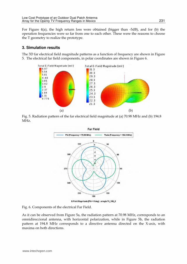
For Figure 4(a), the high return loss were obtained (bigger than -5dB), and for (b) the operation frequencies were so far from one to each other. These were the reasons to choose the T geometry to realize the prototype.
3. Simulation results
The 3D far electrical field magnitude patterns as a function of frequency are shown in Figure 5. The electrical far field components, in polar coordinates are shown in Figure 6.
(a) (b)
Fig. 5. Radiation pattern of the far electrical field magnitude at (a) 70.98 MHz and (b) 194.8 MHz.
Fig. 6. Components of the electrical Far Field.
As it can be observed from Figure 5a, the radiation pattern at 70.98 MHz, corresponds to an omnidireccional antenna, with horizontal polarization, while in Figure 5b, the radiation pattern at 194.8 MHz corresponds to a directive antenna directed on the X-axis, with maxima on both directions.
www.intechopen.com

VLSI Design 232
The Reflection Coefficient magnitude of the antenna is shown in Figure 7, where the peaks of response are located at 70.98 MHz and 194.8 MHz, very near to the selected design operation frequencies (71 MHz and 195 MHz, which correspond to the central frequencies of the two sub-ranges). A zoom at both frequencies is presented in Figures 8 and 9.
Fig. 7. Reflection coefficient magnitude.
Fig. 8. Reflection coefficient magnitude centered at 70.98 MHz, with a minimum return loss of -9.86 dB.
www.intechopen.com

Low Cost Prototype of an Outdoor Dual Patch Antenna Array for the Openly TV Frequency Ranges in Mexico 233
Fig. 9. Reflection coefficient magnitude centered at 194.8 MHz, with a minimum return loss of -18.4 dB.
4. Experimental and practical results
On the base of simulation results, the prototype was fabricated on FR-4 and coupled with coaxial cable of 75 ohms (see Figure 10). In Figure 11, the spectrum analyzer displays the two ranges frequencies received with the prototype: (58.75 MHz, 109.37 MHz) and (155.5MHz, 238.75 MHz), the maximum peak response has a value of -38.5 dBm. Even the primary results shown here, more experimental analysis must be still realized, but it must be recognized that our laboratory equipment is limited.
(a) (b)
Fig. 10. (a) Patch antenna array prototype. (b) Prototype mounted on a PVC base, outdoors of the CIICAp building.
The received range frequencies for the case of a rabbit-ear antenna are shown in Figure 12, where it can be also noted two frequency ranges: (88 Mhz, 108.25 MHz) and (171.25MHz, 182.5 MHz), with a maximum peak of -50 dBm. From these photographs, the bigger
www.intechopen.com

VLSI Design 234
receptions of the patch antenna array are clearly noted, as well as the received power. Even the primary results shown here, more experimental analysis must be still realized.
Fig. 11. Two received range frequencies with the spectrum analyzer with the prototype of the antenna array.
Fig. 12. Two received range frequencies with the spectrum analyzer with a rabbit-ear antenna.
On the other hand, practical tests were also realized on different places of Morelos State. The
first ones were realized outside of CIICAp building (18°58'56'' N, 99°14'1.9'' WO), with the
antenna located approximately at only 2 meters of the ground. The photographs are shown
in Table 7.
Using an analogical TV, a comparison of the reception of the most common channels,
considering two commercial antennas (a mini-combined antenna (Figure 13) and a rabbit-
ear antenna) and the prototype was also realized.
www.intechopen.com

Low Cost Prototype of an Outdoor Dual Patch Antenna Array for the Openly TV Frequency Ranges in Mexico 235
Reception with the prototype
Channel 5 Channel 9
Channel 7 Channel 13
Reception with the commercial combined indoor antenna
Channel 5 Channel 9
Channel 7 Channel 13
www.intechopen.com

VLSI Design 236
Reception with the Rabbit-ear antenna
Channel 5 Channel 9
Channel 7 Channel 13
Table 7. TV channels reception of openly TV using a scanning TV.
Fig. 13. Mini-combined antenna.
As it can be observed from Table 7, the best reception was achieved with the patch antenna array, followed by the reception with the combined antenna, where some problems were appreciated in channels 5 and 13. The antenna with more reception problems was the rabbit-ear antenna.
www.intechopen.com

Low Cost Prototype of an Outdoor Dual Patch Antenna Array for the Openly TV Frequency Ranges in Mexico 237
On the other side, the antenna prototype was also used on a house roof, in three different places using digital TVs. At first, the tests were realized for a household reception in Temixco, Morelos (located at 18. 51° N, 99º13’48’’ WO, with a height over sea level: 1,280 m). In Table 8, photographs of four analogycal representative channels are shown, with a considerable sharpness in all them. In this place, two High Definition (HD) channels were also received (11 and 13; see table 8).
Reception with the prototype
Channel 2 Channel 5
Channel 7 Channel 13
Channel 11 HD Channel 13 HD
Table 8. TV channels reception using a LCD TV.
As second case, other tests were realized considering our prototype and a rabbit-ear antenna
for a household reception in Monte Casino (located at 19°00’53.7’’ N, 99°14’50.6’’ WO, height
over sea level: 2250 m). With the prototype the reception of the analogical channels was
possible without problems, with better sharpness that in the case of the rabbit-ear antenna.
www.intechopen.com

VLSI Design 238
Special attention was focused on signal level of the HD reception of the single channel
received there, due to this attribute of the TV. In Tables 9 and 10 the signal intensities are
shown for both cases.
TV channel Current level (%) Maximum level (%)
13.1 44 48
Table 9. HD reception with a rabbit-ear antenna.
TV channel Current level (%) Maximum level (%)
13.1 50 55
Table 10. HD reception with the patch antenna prototype.
When the prototype was used as outdoor antenna, the maximum intensity reception was obtained (see Table 11 and Figure 14).
TV channel Current level (%) Maximum level (%)
13.1 59 59
Table 11. HD reception with the patch antenna prototype located on the house’s roof.
Fig. 14. Visualized images of HDTV reception antenna using the patch prototype, which is located on the house’s roof.
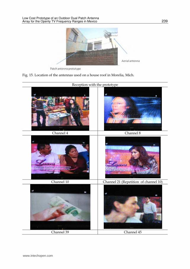
Finally, the third place where the tests were realized was Morelia, Michoacan (19º43' N,
101º12' WO), another Mexican State. The tests were realized using a LCD TV with our
prototype and a commercial aerial antenna (Figure 15). The results are shown in Table 12.
From Table 12, it can be observed that the TV reception is better in the case of the prototype not only for the analogical channels, receiving an additional one, but also for the single HD channel received (1.1). It must be noted that the location of both antennas is not the best (Figure 15), but several homes in our country have similar conditions. The sizes of the antenna array prototype are considerable smaller than the available aerial antenna.
www.intechopen.com
Low Cost Prototype of an Outdoor Dual Patch Antenna Array for the Openly TV Frequency Ranges in Mexico 239
Fig. 15. Location of the antennas used on a house roof in Morelia, Mich.
Reception with the prototype
Channel 4 Channel 8
Channel 10 Channel 21 (Repetition of channel 10)
Channel 39 Channel 45
www.intechopen.com

VLSI Design 240
Channel 13 (HD) Channel 1.1
Reception with the commercial aerial antenna
Channel 4 Channel 8
Channel 10 Channel 21 (Repetition of channel 10)
Channel 39 Channel 45
www.intechopen.com

Low Cost Prototype of an Outdoor Dual Patch Antenna Array for the Openly TV Frequency Ranges in Mexico 241
Not available
Channel 13 (HD) Channel 1.1
Table 12. Visualized images of TV received with antennas located on the house’s roof.
5. Conclusions
The simulations of the patch antenna array show its dual frequency performance. In spite of the inherent narrow broadband of the microstrip antennas, the practical reception, realized in different geographical sites of Morelos and in Morelia, Michoacan, has also confirmed the feasibility of its use for household reception of openly TV frequency ranges.
The difference in the TV reception can be attributed to the proximity of the repeaters antennas, and to the elevation conditions. The vegetation is also relevant.
The experimental and practical tests show an acceptable reception of channels in both VHF sub-ranges of frequencies.
In TVs that accounts with graphical signal meter, it was possible to observe that with the antenna on the house’s roof, the current signal meter obtained its maximal level, for the case of HD channels, which is certainly a very good practical result, and it constitutes a base to suggest its use as outdoor antenna.
In the three tests realized using digital TVs on different places, it must be mentioned that unfortunately the available TVs have different attributes, but in all cases the better reception was obtained with our prototype. The comparison with aerial antennas was only possible where they were available.
The prototype sizes make it a competitive option compared with some commercial aerial antennas available in the market. Additionally, for the case of digital TVs, it does not require of an amplifier or a rotor, once it was properly directed. For the case of analogical TVs the reception improvement is considerable compared with the options shown here.
As future work, it is planned to design an appropriate radome for protection of the prototype to the weather.
The implementation of geometry modifications is also been considered in order to increment the broadband of the antenna array. Its sizes can be also reduced using another material, but its costs will be incremented.
6. Acknowledgment
The authors wish to thank to EM Software & Systems (USA) Inc., for FEKO license. J. G. Vera-Dimas and J. A. Damián Morales acknowledge financial support from CONACYT
www.intechopen.com

VLSI Design 242
scholarships under grants 270210/219230 and 336781/235572, respectively. R. Vargas-Bernal acknowledges partial financial support from PROMEP.
7. References
Balanis, Constantine. (2005). Antenna Theory. Third edition. Wiley-Interscience, Hoboken, ISBN: 047166782X, New Jersey.
Barir, Syfaul & Hamid, Sofian (2010), A Novel Microstrip Patch antenna for 470-890 MHz Indoor Digital Television Receiver. Digital Proc. Of IMMAC 2010. 2010 Indonesia-Malaysia Microwave Antenna Conference, Depok, Indonesia, June 11-12.
Brown, T. W. C.; Saunders, S. R.; Stavrou, S. & Fiacco, M. (2007), Characterization of Polarization Diversity at the Mobile. IEEE Transactions on Vehicular Technology, Vol. 56, No. 5, pp. 2440-2447.
COFETEL, (2008), Infraestructura de Estaciones de Televisión. August 2008. Available from: <http://www.cofetel.gob.mx/es/Cofetel_2008/Cofe_estaciones_de_television_in>
Garg, Ramesh; Bhartia Prakash; Bahl, Inder & Ittipiboon, Apisak. (2001). Microstrip Antenna Design Handbook, Artech House Inc., ISBN:0890065136, Boston. London.
INEGI, (2009), Encuesta Nacional sobre disponibilidad y uso de tecnologías de información y comunicaciones en los hogares. August 2011. Available from
<http://www.inegi.org.mx/prod_serv/contenidos/espanol/bvinegi/productos/encuestas/especiales/endutih/ENDUTIH_2009.pdf>.
INEGI, (2010), Population and Housing Census 2010: Private homes with television. September 2011. Available from: <http://www.inegi.org.mx/sistemas/mexicocifras/MexicoCifras.aspx?e=0&m=0&sec=M&ind=1003000021&ent=0&enn=Mexico&ani=2010&i=i&src=0>.
Kapinas, Vasilios M.; Ilić, Maja; Karagiannidis, George K., & Pejanović-Ðurišić, Milica. (2007), Aspects on Space and Polarization Diversity in Wireless Communication Systems. 15th Telecommunications forum TELFOR 2007, pp. 183-186, Serbia, Belgrade, November 20-22, 2007.
Melissinos, Adrian C. (1990). Principles of Modern Technology. Cambridge University Press, ISBN 9780521352499, Cambridge.
Neelakanta, Perambur S. & Chatterjee, Rajeswari. (2003). Antennas for Information Super Skyways: An Exposition on Outdoor and Indoor Wireless Antennas. Research Studies Press LTD, ISBN 0-86380-267-2, Baldock, Hertfordshire, England.
Rathod, Jagdish M. (2010), Design Development of Antenna for TV Transmission for Connecting Outdoor Broadcasts Van to the Studio for Rural Areas. International Journal of Computer and Electrical Engineering, Vol. 2, No. 2, pp. 251-256.
Jalife, Villalón Salma & Sosa, Plata Gabriel (2007), Radiodifusión y Telecomunicaciones: Aspectos técnicos fundamentales. August 2010. Available from:
http://www.senado.gob.mx/telecom_radiodifusion/content/sesiones_trabajo/ docs/Salma_Gabriel.pdf>
Smith, Christopher B. (2008), Wideband Dual-Linear Polarized Microstrip Patch Antenna, Thesis of Master of Science, Texas A&M University, December 2008, United States of America.
Taguchi, Mitsuo Nakamura; Takuya, Fujimoto Takafumi & Tanaka, Kazumasa (1996), CPW Fed Active loop Antenna for Television Receivers. Proceedings of ISAP’96, pp. 521-524, Chiba, Japan.
Wang, Qingyuan & Lecours Michel (1999), Dual-frequency microstrip antenna with orthogonal polarization. Laboratoire de Radiocommunications et de Traitement du Signal. Rapport annuel d’activités 1998-1999, pp. 85-90.
www.intechopen.com

VLSI DesignEdited by Dr. Esteban Tlelo-Cuautle
ISBN 978-953-307-884-7Hard cover, 290 pagesPublisher InTechPublished online 20, January, 2012Published in print edition January, 2012
InTech EuropeUniversity Campus STeP Ri Slavka Krautzeka 83/A 51000 Rijeka, Croatia Phone: +385 (51) 770 447 Fax: +385 (51) 686 166www.intechopen.com
InTech ChinaUnit 405, Office Block, Hotel Equatorial Shanghai No.65, Yan An Road (West), Shanghai, 200040, China
Phone: +86-21-62489820 Fax: +86-21-62489821
This book provides some recent advances in design nanometer VLSI chips. The selected topics try to presentsome open problems and challenges with important topics ranging from design tools, new post-silicon devices,GPU-based parallel computing, emerging 3D integration, and antenna design. The book consists of two parts,with chapters such as: VLSI design for multi-sensor smart systems on a chip, Three-dimensional integratedcircuits design for thousand-core processors, Parallel symbolic analysis of large analog circuits on GPUplatforms, Algorithms for CAD tools VLSI design, A multilevel memetic algorithm for large SAT-encodedproblems, etc.
How to referenceIn order to correctly reference this scholarly work, feel free to copy and paste the following:
M. Tecpoyotl-Torres, J. A. Damián Morales, J. G. Vera Dimas, R. Cabello Ruiz, J. Escobedo-Alatorre, C. A.Castillo-Milián and R. Vargas-Bernal (2012). Low Cost Prototype of an Outdoor Dual Patch Antenna Array forthe Openly TV Frequency Ranges in Mexico, VLSI Design, Dr. Esteban Tlelo-Cuautle (Ed.), ISBN: 978-953-307-884-7, InTech, Available from: http://www.intechopen.com/books/vlsi-design/low-cost-prototype-of-an-outdoor-dual-patch-antenna-array-for-the-openly-tv-frequency-ranges-in-mexi