low activity waste pretreatment system · low activity waste pretreatment system ... 74 4.8...
TRANSCRIPT

Project Number: 31269 (T5L01)
Doc. No.: 15-2-007
Date: September 9, 2016
Revision: 1
Page 1 of 89
LOW ACTIVITY WASTE PRETREATMENT SYSTEM
Project No. 31269 (T5L01)
Document No. 15-2-007
Safety Related ⌧ Non-Safety Related ¨
WEATHER ENCLOSURE CRANE SPECIFICATION
210LP-PA-BC-CRN-001
Prepared for
Washington River Protection Solutions, LLC
Revision: 1 Status: Approved for Bid
Project Number: 31269 (T5L01)
Doc. No.: 15-2-007
Date: September 9, 2016
Revision: 1
Page 2 of 89
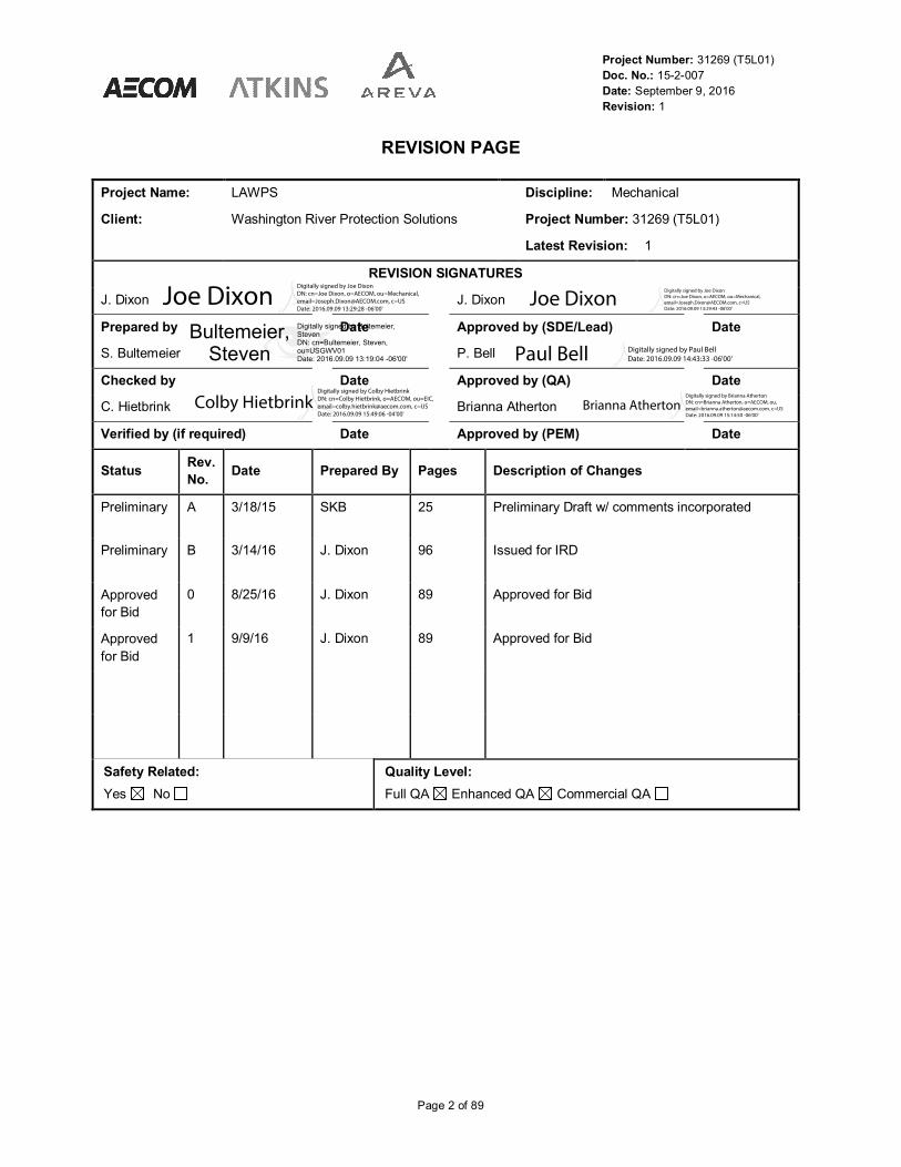
REVISION PAGE
Project Name: LAWPS Discipline: Mechanical
Client: Washington River Protection Solutions Project Number: 31269 (T5L01)
Latest Revision: 1
REVISION SIGNATURES
J. Dixon J. Dixon
Prepared by Date Approved by (SDE/Lead) Date
S. Bultemeier P. Bell
Checked by Date Approved by (QA) Date
C. Hietbrink Brianna Atherton
Verified by (if required) Date Approved by (PEM) Date
StatusRev.
No.Date Prepared By Pages Description of Changes
Preliminary A 3/18/15 SKB 25 Preliminary Draft w/ comments incorporated
Preliminary B 3/14/16 J. Dixon 96 Issued for IRD
Approved
for Bid
0 8/25/16 J. Dixon 89 Approved for Bid
Approved
for Bid
1 9/9/16 J. Dixon 89 Approved for Bid
Safety Related:
Yes No
Quality Level:
Full QA Enhanced QA Commercial QA
Date DateDigitally signed by Bultemeier,StevenDN: cn=Bultemeier, Steven,ou=USGWV01Date: 2016.09.09 13:19:04 -06'00'
Bultemeier,Steven
Joe DixonDigitally signed by Joe Dixon
DN: cn=Joe Dixon, o=AECOM, ou=Mechanical,
[email protected], c=US
Date: 2016.09.09 13:29:28 -06'00'Joe Dixon
Digitally signed by Joe Dixon
DN: cn=Joe Dixon, o=AECOM, ou=Mechanical,
[email protected], c=US
Date: 2016.09.09 13:29:43 -06'00'
Colby HietbrinkDigitally signed by Colby Hietbrink
DN: cn=Colby Hietbrink, o=AECOM, ou=EIC,
[email protected], c=US
Date: 2016.09.09 15:49:06 -04'00'
Paul Bell Digitally signed by Paul Bell
Date: 2016.09.09 14:43:33 -06'00'
Brianna AthertonDigitally signed by Brianna Atherton
DN: cn=Brianna Atherton, o=AECOM, ou,
[email protected], c=US
Date: 2016.09.09 15:14:50 -06'00'

Project Number: 31269 (T5L01)
Doc. No.: 15-2-007
Date: September 9, 2016
Revision: 1
Page 3 of 89
TABLE OF CONTENTS
1.0 SCOPE ............................................................................................................................ 11
1.1 Introduction ......................................................................................................................... 11
1.2 Purpose .............................................................................................................................. 11
2.0 Applicable Documents ................................................................................................... 13
2.1 Government Documents ..................................................................................................... 13
2.2 Non-Government Documents .............................................................................................. 13
2.3 Non-Code of Record Documents ........................................................................................ 14
3.0 Technical Requirements ................................................................................................ 16
3.1 Item Definition ..................................................................................................................... 16
3.2 Characteristics .................................................................................................................... 16
3.3 Design and Construction ..................................................................................................... 18
3.4 VENDOR Supplied Items .................................................................................................... 18
3.5 BUYER Supplied Items ....................................................................................................... 18
3.6 General Design ................................................................................................................... 19
3.7 Structural Design ................................................................................................................ 19
3.8 Bumpers ............................................................................................................................. 23
3.9 Mechanical Design ............................................................................................................. 23
3.10 Mechanical Electrical Design .............................................................................................. 33
3.11 Electrical Design ................................................................................................................. 35
3.12 Limit Switches and Safety Devices ...................................................................................... 41
3.13 Approved Materials ............................................................................................................. 47
3.14 Material Traceability ............................................................................................................ 47
3.15 Surface Preparation and Finish ........................................................................................... 48
3.16 Control of Nonconforming Items .......................................................................................... 49
3.17 Environment ....................................................................................................................... 49
3.18 Submittals and Technical Documentation ............................................................................ 50
4.0 Quality Assurance Requirements ................................................................................. 66
4.1 General .............................................................................................................................. 66
4.2 Inspection and Testing ........................................................................................................ 67
4.3 Inspection of Work .............................................................................................................. 68
4.4 Receipt Inspection .............................................................................................................. 71
4.5 Non-compliances and Non-conformance ............................................................................. 72
4.6 VENDOR Procurement of Safety Significant Items/Materials ............................................... 72
4.7 Suspect/Counterfeit Items ................................................................................................... 74
4.8 Measuring and Test Equipment........................................................................................... 74

Project Number: 31269 (T5L01)
Doc. No.: 15-2-007
Date: September 9, 2016
Revision: 1
Page 4 of 89
4.9 Acceptance Criteria ............................................................................................................ 74
4.10 Certificate of Conformance:................................................................................................. 75
4.11 Verification .......................................................................................................................... 75
4.12 Testing .............................................................................................................................. 76
5.0 Preparation for Delivery ................................................................................................. 80
5.1 General .............................................................................................................................. 80
5.2 Cleanness and Foreign Material Exclusion .......................................................................... 80
5.3 Marking .............................................................................................................................. 80
5.4 Shipping and Storage ......................................................................................................... 81
6.0 Installation ...................................................................................................................... 82
6.1 Installation, Start-up, and Site Testing ................................................................................. 82
6.2 Site Inspections and Testing ............................................................................................... 82
7.0 Notes ............................................................................................................................... 84
Appendix A: Engineering Forms ............................................................................................ 85

Project Number: 31269 (T5L01)
Doc. No.: 15-2-007
Date: September 9, 2016
Revision: 1
Page 5 of 89
Acronyms and Abbreviations
AGMA American Gear Manufacturers Association
AISC American Institute of Steel Construction
AIST Association of Iron and Steel Technology
ANSI American National Standards Institute
AR Approval Request
ASME American Society of Mechanical Engineers
ASNT American Society for Nondestructive Testing
ASTM American Society for Testing and Materials
AVS Acquisition Verification Services
AWS American Welding Society
BTH Below The Hook
CAD Computer Aided Design
CCTV Closed Circuit TV
CD Compact Disk
CFR Code of Federal Regulations
CGD Commercial Grade Dedication
CGI Commercial Grade Item
CMAA Crane Manufacturer’s Association of America
CMTR Certified Materials Test Report
COC Certificate of Conformance
CQA Commercial Quality Assurance
Cs Cesium
CWI Certified Weld Inspector
DBE Design Basis Event
DCN Design Change Notice
DPD Design Proposal Drawing
DOE Department of Energy
DST Double Shell Tanks
DVD Digital Versatile Disk
DVR Digital Video Recorder
ECMA Electrification and Controls Manufacturers Association
ECN Engineering Change Notice
EQA Enhanced Quality Assurance
ESL Evaluated Supplier List

Project Number: 31269 (T5L01)
Doc. No.: 15-2-007
Date: September 9, 2016
Revision: 1
Page 6 of 89
Acronyms and Abbreviations
FAT Factory Acceptance Test
FQA Full Quality Assurance
GFCI Ground-Fault Circuit Interrupter
Hz Hertz
HIC High Integrity Container
HLW High Level Waste
ICS Industrial Control Systems
IEC International Engineering Consortium
IHLW Immobilized High Level Waste
ILAC International Laboratory Accreditation Cooperation
ILAW Immobilized Low Level Waste
ISO International Organization for Standardization
LAW Low Activity Waste
LAWPS Low Activity Waste Pretreatment System
LED Light-Emitting Diode
M&TE Measuring and Test Equipment
MDS Main Disconnect Switch
MSR Master Submittal Register
MT Magnetic Particle
MTBF Mean Time between Failures
MTTF Mean Time to Failure
NACLA National Cooperation for Laboratory Accreditation
NCSL National Conference of Standards Laboratories
ND Nondestructive
NDT Nondestructive Testing
NDE Nondestructive Examination
NEC National Electrical Code
NEMA National Electrical Manufacturers Association
NFPA National Fire Protection Association
NIST National Institute of Standards and Technology
NOG Nuclear Overhead and Gantry Cranes
NPH Natural Phenomena Hazards
NQA Nuclear Quality Assurance
OEM Original Equipment Manufacturer

Project Number: 31269 (T5L01)
Doc. No.: 15-2-007
Date: September 9, 2016
Revision: 1
Page 7 of 89
Acronyms and Abbreviations
OSHA Occupational Health and Safety Administration
PC Performance Category
PCB Polychlorinated Biphenyl
PDF Printer Description File
PE Professional Engineer
PLC Programmable Logic Controller
QA Quality Assurance
QAP Quality Assurance Program
QL Quality Level
RFI Request For Information
ROM Read-only Memory
RCSC Research Council on Structural Connections
SAE Society of Automotive Engineers
SAT Site Acceptance Test
SCI Suspect Counterfeit Item
SDC Seismic Design Category
SDS Safety Data Sheet
SOW Statement of Work
SS Safety Significant
SSE Safe Shutdown Earthquake
SSC Safety Significant Components
TEBC Totally Enclosed Blower Cooled
TEFC Totally Enclosed Fan Cooled
TENV Totally Enclosed Non-Ventilated
TOC Tank Operations Contractor
SNT Society for Non-Destructive Testing
UL Underwriters Laboratories
UDS Utility Disconnect Switch
UPS Uninterruptable Power Supply
VAC Volts Alternating Current
WAC Waste Acceptance Criteria
WRPS Washington River Protection Solutions
WS With Shipment
WTP Waste Treatment Plant

Project Number: 31269 (T5L01)
Doc. No.: 15-2-007
Date: September 9, 2016
Revision: 1
Page 8 of 89
Units
U.S. customary units
Definitions
BUYER – The company for whom the VENDOR is performing work or services.
AVS Quality Clauses – The AVS Quality Clauses are standard procurement quality clauses for the
procurement of items and services. The clauses establish contractual obligations for quality program
systems, identification, traceability, documents submittals, testing, reporting, qualification, special process
controls, inspections, etc.
Body Bound Bolt – A bolt whose fit in the hole is closely machined or reamed to have a tolerance tight
enough to where it will require force to insert the bolt such as a light interference fit. These bolts are used
in shear to ensure that the joints are not able to shift under load and deflection.
DESIGN BASIS EVENT - A postulated accident that a nuclear facility must be designed and built to
withstand without loss to the systems, structures, and components necessary to assure public health and
safety.
DESIGN CHANGE – Within the context of this specification, a DESIGN CHANGE is technically equivalent
to a SUBSTITUTION (see SUBSTITUTION). However, the term DESIGN CHANGE may be used to refer
to more significant changes to the design compared to a simple substitution.
DEVIATION – any departure from the requirements contained in the purchase order and specification
which VENDOR proposes to incorporate if approved by BUYER.
ENHANCED QUALITY ASSURANCE (EQA) - Level of controls for those items, services, or processes
where, based on an evaluation of risk or nuclear safety, additional controls beyond the providers
published or stated attributes of the item, service, or process are needed to verify critical attributes.
FULL QUALITY ASSURANCE (FQA) - Level of controls applied for items services, or processes that are
commensurate with the controls invoked under ASME NQA-1 or other appropriate national consensus
standard.
HANDLING - The movement or transportation of items following receipt from offsite/project locations. This
includes movement within storage areas and movement/transportation from receipt or storage areas to
field locations. Handling requirements include the need for special handling tools and equipment,
restrictions on material composition of surfaces in contact with the item, protection against damage or
deterioration, which could occur during movement and placement, protection against physical damage
due to excessive shock or vibration, and protection against entry of dirt, water, or other contaminants.
HOLD POINT – A mandatory inspection activity beyond which work shall not proceed until (1) the
inspection is performed by an independent inspector and/or BUYER and acceptance is authenticated, or
(2) a written release is authorized by the organization who established the hold point.

Project Number: 31269 (T5L01)
Doc. No.: 15-2-007
Date: September 9, 2016
Revision: 1
Page 9 of 89
Jacking Pad – A structural member attached to the end truck of a crane used to attach a jack to for lifting
of the end truck.
LOAD BEARING – Items identified as loading bearing in the crane design will be those that could cause
a dropped load upon failure in any event up to and including a Design Basis Event.
LOAD PATH – Includes all items on a crane whose failure could result in the uncontrolled drop of the
crane or crane load.
MORE CONSERVATIVE – “More conservative” shall be interpreted as “more protective of the health,
safety and well-being of Site workers and facilities, the public, and environment, as applicable.”
NONCONFORMANCE – a deficiency in component characteristic, as defined in BUYER approved
drawings and documents.
Primary Weld – All welds that are load bearing are considered primary welds.
PRODUCT DATA – Printed information including, but not limited to, catalog cuts, color charts,
illustrations, diagrams, templates, performance curves, brochures, and other forms of product literature.
QUALITY ASSURANCE RECORDS – Quality assurance plans, procedures, and records, including
completed documents that furnish evidence of the quality of an item or activities affecting quality.
RATED LOAD – The maximum load that can be lifted by the device.
SHALL / MUST – Denotes project requirements, compliance is required
SHOULD – Denotes recommendation or expectation, compliance is expected.
SHIPPING – The movement of items from an off-site/project location (Manufacturer, warehouse, etc.) to
an on-site/project location, or movement from an onsite/project location to an off-site/project location.
Shipping requirements include packaging and securing of items to protect against damage or
deterioration which could occur during movement and transportation, protection against physical damage
due to excessive shock or vibration, protection against entry of dirt, water, or other contaminants, and
protection against other environmental conditions such as temperature or humidity.
SPECIFICATION – Refers to any design, fabrication or supply specification.
STORAGE – Holding of items in areas that address: the probable maximum period to be held, the
inherent physical limitations of the item itself, and required protection from potential hazards such as fire,
corrosion, chemical attack and environmental conditions. Storage also includes the requirements for
maintaining the integrity and operability of items through routine maintenance, cleaning, or other means
of preservation.
SUBSTITUTION – Any change or deviation from issued approved drawings, designs, methods, or
contract terms and conditions. Changes in products, materials, equipment, methods of construction, and
test criteria required by the Contract Documents proposed by the VENDOR after award of the Contract
are considered to be requests for substitution.
Project Number: 31269 (T5L01)
Doc. No.: 15-2-007
Date: September 9, 2016
Revision: 1
Page 10 of 89
SPECIFICATION – Refers to any design, fabrication or supply specification.
VENDOR – The Company responsible for the supply of equipment or services.
WILL – Denotes a statement of fact
WITNESS POINT – An inspection activity beyond which work shall not proceed until an inspector and/or
BUYER is notified and (1) the inspection is performed and released, or (2) the inspection is deferred and
can be completed at a later time, or (3) a written waiver is issued by the organization who established the
witness point.

Project Number: 31269 (T5L01)
Doc. No.: 15-2-007
Date: September 9, 2016
Revision: 1
Page 11 of 89
1.0 SCOPE
1.1 Introduction
The Hanford Site located in Washington State contains the largest quantity of legacy tank waste
in the Department of Energy (DOE) complex. Most of these nuclear wastes, resulting from the
processing operations of defense nuclear materials, are stored in underground storage tanks,
containing hazardous and radioactive liquids, sludge, and saltcake. These tanks are located on
the Central Plateau of the Hanford Site in 200 East and 200 West Areas, and are connected by a
cross-site transfer system.
The Waste Treatment and Immobilization Plant (WTP) Project was established for processing
and immobilizing Hanford tank waste by vitrification (i.e., glass). The WTP process flow was
designed to pretreat feed from the tank farms, separate it into high level waste (HLW) and low
activity waste (LAW) fractions, and vitrify each fraction in a separate facility. The vitrified waste
would be poured directly into stainless steel canisters for containment during production. The
immobilized HLW (IHLW) would be interim stored onsite and eventually disposed at a HLW
geologic repository, and the immobilized low activity waste (ILAW) would be disposed on the
Hanford Site.
The primary mission of the Low Activity Waste Pretreatment System (LAWPS) provides for the
early production of ILAW by treating tank supernatant waste and providing treated LAW feed to
the WTP LAW Facility for immobilization. Tank waste from Hanford double-shell tanks (DST) is
treated for removal of solids and separation of Cesium-137 (137
Cs) isotope from the filtered waste
stream to levels that are compliant with WTP LAW Immobilization Facility Waste Acceptance
Criteria (WAC). The solids and concentrated Cesium (Cs) liquid waste are returned to the Tank
Farm DST system. LAWPS stores the treated LAW product before transferring to the WTP. The
LAWPS collects and routes system generated liquid effluent to the DST System. LAWPS
transfers spent resin to a High Integrity Container (HIC) for disposal.
The LAWPS Project also includes a pipeline for routing the secondary liquid waste and out-of-
specification returns from WTP to the DST system.
1.2 Purpose
The intent of this specification is to procure the design, fabrication, examination, testing,
packaging, shipping, installation, and start up testing services necessary to provide a bridge
crane for use in maintenance activities in the main operating area of the LAWPS Weather
Enclosure. The maintenance activities identified include both manned operation and remote
operation of the crane due to elevated radiation levels of some of the components being handled.
The Weather Enclosure Crane is a top running double girder bridge crane. The crane has a
custom underhung auxiliary hoist system underhung on the south girder of the bridge. The
auxiliary hoist system has two hoists on one trolley that can rotate about the center of the trolley.

Project Number: 31269 (T5L01)
Doc. No.: 15-2-007
Date: September 9, 2016
Revision: 1
Page 12 of 89
The operation of the crane will be both wired and wireless. This allows operators to command the
crane using the provided CCTV system or locally using a mobile control station.
The crane data sheet, 210LP-PA-BC-CRN-001, contains the design inputs and functional
requirements (capacity, span, speeds, etc.) specific to the Weather Enclosure Crane. The design
of the crane shall accommodate the installation envelope as shown in the Design Proposal
Drawings (DPD). The crane is classified as Safety Significant (SS). It shall be designed and built
to Full Quality Assurance (FQA) requirements for all load path components and Enhanced Quality
Assurance (EQA) for the remainder of the items.
The BUYER shall be advised immediately in writing of any conflicts as soon as they are identified.
No substitutes or deviations to this specification will be allowed without written approval from
BUYER.

Project Number: 31269 (T5L01)
Doc. No.: 15-2-007
Date: September 9, 2016
Revision: 1
Page 13 of 89
2.0 APPLICABLE DOCUMENTS
The following documents, of the exact issue shown, form a part of the BUYER basis of design to
the extent specified in the applicable sections of this document and establish the Code of Record.
In the event of a conflict between documents referenced herein, and the requirements of this
specification or data sheet, the requirements of this specification shall take precedence only when
this specifications’ requirements are more stringent or conservative.
2.1 Government Documents
10 CFR 830 Nuclear Safety Management
10 CFR 835 Occupational Radiation Protection
29 CFR 1910 Occupational Safety and Health Administration (OSHA)
29 CFR 1910.179
29 CFR 1910.23
Overhead and gantry cranes (OSHA)
Guarding Floor and Wall Openings and Holes (OSHA)
29 CFR 1910.27 Fixed Ladders (OSHA)
DOE-RL-92-36,
Release 74 (2014)
Hanford Site Hoisting and Rigging Manual
DOE G 414.1-3 (2004) Suspect/Counterfeit Items Guide
DOE Order 414.1D Quality Assurance
2.2 Non-Government Documents
ASME NQA-1, 2008 and
2009A
Quality Assurance Program Requirements for Nuclear Facilities
ASME NOG-1, 2010
ASME NUM-1, 2009
AWS D1.1/, 2010
Rules for Construction of Overhead and Gantry Cranes (Top
Running Bridge, Multiple Girder)
Rules for Construction of Cranes, Monorails, and Hoist (With Bridge
or Trolley or Hoist of the Underhung Type)
Structural welding Code-Steel
AWS D14.1/D14.1M, 2005 Specification for Welding of Industrial and Mill Cranes and Other
Material Handling Equipment
NFPA 70, 2014 National Electrical Code [NEC]

Project Number: 31269 (T5L01)
Doc. No.: 15-2-007
Date: September 9, 2016
Revision: 1
Page 14 of 89
NEMA MG-1, 2014 Motors and Generators
NEMA MG-2, 2014 Safety Standard for Construction and Guide for Selection,
installation and Use of Electric Motors and Generators
2.3 Non-Code of Record Documents
47 CFR 15 (FCC part 15); Radio Frequency Devices
TFC-BSM-IRM_DC-C-07 Vendor Processes
TFC-ENG-STD-12, Rev D Tank Farm Equipment Identification Numbering and Labeling
Standard
AISC/RCSC Specification for Structural Joints Using High-Strength Bolts
AIST Technical Report #6 Specification for Electric Overhead Traveling Cranes for Steel Mill
Service
AGMA 2001 Fundamental Rating Factors and Calculation Methods for Involute
Spur and Helical Gear Teeth
AGMA 2015-1 Accuracy classification System – Tangential Measurements for
Cylindrical Gears
AGMA 6001 Design and Selection of Components for Enclosed Gear Drives
AGMA 6109 Standard for gearmotor, Shaft Mounted and screw Conveyor Drives
AGMA 6013 Standard for Industrial Enclosed Gear Drives
AGMA 908 Geometry Factors for Determining the Pitting Resistance and
Bending Strength of Spur, Helical and Herringbone Gear Teeth
ANSI ECMA 15 Specifications for Cable-less (Wireless) Control
ANSI Z359 Fall Protection Code
ASME BTH-1, 2014 Design of Below-the-Hook Lifting Devices
ASME B17.1 Keys and Keyseats
ASME B18.8.2 Taper Pins, Dowel Pins, Straight Pins, Grooved Pins, and Spring
Pins (Inch Series)
ASME B30.10, 2014 Hooks (Safety Standard for Cableways, Cranes, Derricks, Hoists,
Hooks, Jacks, and Slings)
ASME B30.11, 2004 Monorails and Underhung Cranes (Safety Standard for Cableways,
Cranes, Derricks, Hoists, Hooks, Jacks, and Slings)
ASME B30.2, 2011 Overhead and Gantry Cranes (Top Running Bridge, Single or
Multiple Girder, Top Running Trolley Hoist)

Project Number: 31269 (T5L01)
Doc. No.: 15-2-007
Date: September 9, 2016
Revision: 1
Page 15 of 89
ASME B30.20, 2013 Below-the-Hook Lifting Devices
ASME Y14.5 Dimensioning and Tolerancing (Engineering Drawing and Related
Documentation Practices)
ASNT SNT-TC-1A, 2011 Recommended Practice for Personnel Qualification and
Certification in Nondestructive Testing
ASTM A325 Standard Speci cation for Structural Bolts, Steel, Heat Treated,
120/105 ksi Minimum Tensile Strength
ASTM A388 Standard Practice for Ultrasonic Examination of Steel Forgings
ASTM A490 Standard Specification for High-Strength Steel Bolts
ASTM A504 Standard Specification for Wrought Carbon Steel Wheels
ASTM A536 Standard Specification for Ductile Iron Castings
ASTM A563, 2015 Standard Specification for Carbon and Alloy Steel Nuts
ASTM A931, 2013 Standard Test Method for Tension testing of Wire Ropes and
Strand
ASTM E709 Standard Guide for Magnetic Particle Testing
ASTM F436 Standard Specification for Hardened Steel Washers
ASTM F3125/F3125M Standard Specification for High Strength Structural Bolts, Steel and
Alloy Steel, Heat Treated, 120 ksi (830 MPa) and 150 ksi (1040
MPa) Minimum Tensile Strength, Inch and Metric Dimensions
AWS QC1-2007 Standard for AWS Certification of Welding Inspectors
CMAA 70, 2010 Specifications for Top Running Bridge & Gantry Type Multiple
Girder Electric Overhead Traveling Cranes
CMAA 74, 2010 Specifications for Top Running Bridge & Under Running Single
Girder electric traveling Cranes utilizing under running Trolley Hoist
NEMA ICS 8 Crane and Hoist Controllers (Industrial Control and Systems)
Wire Rope Users Manual Wire Rope Technical Board (WRTB), 4th Edition, 2005
Form A-6009-317 Master Submittal Register (MSR)
Form A-6005-315 Transmittal Letter
Form A-6003-417 Requests for Information (RFI)
Form A-6002-544 Critical characteristics for CGI
Form A-6006-661 WRPS Quality Assurance Requirements

Project Number: 31269 (T5L01)
Doc. No.: 15-2-007
Date: September 9, 2016
Revision: 1
Page 16 of 89
3.0 TECHNICAL REQUIREMENTS
This section will describe the purpose, interface and design requirements of the Weather
Enclosure Crane.
3.1 Item Definition
The Weather Enclosure Crane is a top running bridge crane with an underhung dual auxiliary
hoist intended for maintenance activities in the LAWPS weather enclosure.
3.2 Characteristics
3.2.1 Functional Characteristics
The crane shall be designed to remotely maintain the process equipment within the LAWPS
Weather Enclosure. The crane may also be used for installation of the pit equipment during the
construction phase. Some of the known items that will be maintained and lifted by the crane are:
– Shield plates (heaviest item to be picked – 19.6ton)
– Process pumps (tallest item to be picked – 32ft)
– Eductors
– Jumpers
– Ion exchange columns
The bridge of the crane will travel in the North/South direction. The crane shall be capable of
uprighting and translating the process pumps. Due to the height of the pumps, this will require
both hoisting and trolley motion. It is preferred that this is performed using the hoist motion alone
by releasing the trolley brakes during uprighting. Releasing the trolley brakes shall be performed
at both the wireless control station and the main control station. The lateral force created by
hoisting and pivoting shall then translate the bridge and trolley without the use of the bridge and
trolley drive power.
3.2.2 Reliability
The crane will be designed to meet the CMAA 70 Class D heavy service design to ensure
reliability of the system.
3.2.3 Inspectability
The crane runway will have a maintenance platform running the length of the building under the
runway to allow access to the crane anywhere in the building. The crane shall be provided with a
maintenance walkway along the north girder of the crane to ensure that the trolley can be
accessed by maintenance personnel no matter the location of the trolley in the facility.

Project Number: 31269 (T5L01)
Doc. No.: 15-2-007
Date: September 9, 2016
Revision: 1
Page 17 of 89
3.2.4 Maintainability
The crane shall be designed and built so that any items requiring maintenance or replacement
are easily accessible by maintenance personnel. Since this is a radiological environment, any
items that are known to require replacement shall be designed for simple change out requiring
minimal tooling. The camera on the lower block shall be designed with a quick change mount
that does not require tools and have a quick change electrical fitting.
3.2.5 Environment
The crane is operated indoors and details are described in the included crane data sheet.
3.2.6 Transportation and Storage
The crane will be transported and stored by the crane VENDOR. The transportation and storage
of the crane are described in section 5.0 below and the scope of work documents provided with
this request for proposal.
3.2.7 Safety
The crane is classified as SS. It shall be designed and built to FQA requirements for all main hoist
load path components and the below listed components that support the operation of the main
hoist load path items.
- The Main Hoist Final Overtravel High Limit Switch
- Drum Over Speed Detection Switch
- Wire Rope Hoist Mis-Reeve Limit Switch
- Secondary Main Hoist Brake (Drum Brake)
- Safety Control Circuit
All other items shall be classified as EQA including the auxiliary hoists, and are not required to
meet the SS requirements that the main hoist is required to meet. The VENDOR is to provide a
list of load path items for approval by the BUYER.
The following items are identified as the safety functions of the Weather Enclosure Crane:
- Prevent damaging interactions with SS SSCs during design basis NPH events.
- Maintain control of lifted loads during normal operations
- Maintain control of lifted loads during design basis seismic event (and after the DBE)
The crane is required to meet these requirements for a SDC-3 seismic event and meet Limit
State A as well as the NOG-1 requirements for allowable stresses in a seismic event.
Project Number: 31269 (T5L01)
Doc. No.: 15-2-007
Date: September 9, 2016
Revision: 1
Page 18 of 89
3.3 Design and Construction
All portions of the crane design shall be performed by, or under direct supervision of, a
competent engineer experienced in the particular engineering discipline. The engineer shall be
intimately familiar with the crane contract specification and the details of the proposed crane
design. The engineer shall be an in-house employee of the crane VENDOR unless otherwise
approved by the BUYER.
3.4 VENDOR Supplied Items
Equipment and services provided by the crane VENDOR shall include, but not be limited to, the
following:
3.4.1 The VENDOR shall provide the engineering services, labor, materials, tools, drawings, and
equipment necessary to design, fabricate, assemble, shop test, and deliver the crane,
including all associated components specified herein, to an intermediate storage site, near
the LAWPS facility on the Hanford site outside Richland Washington.
3.4.2 The VENDOR shall provide an installation consultant for the crane in the new facility. The
duration is to be estimated by the VENDOR and explained in the response to this crane
specification.
3.4.3 The VENDOR shall provide a test director and other technical personnel as needed to
perform the Crane Start-up Procedure, Site Acceptance Testing, Maintenance Inspection,
and Initial Load Testing in the facility.
3.4.4 The VENDOR shall provide, at no additional cost, such support as may be determined and
required to address VENDOR-accountable design and fabrication issues that emerge during
the installation and start up testing period.
3.4.5 The VENDOR shall provide training to the BUYERS operators in operation, inspection,
troubleshooting and maintenance.
3.5 BUYER Supplied Items
3.5.1 BUYER will provide the building mounted crane runway girder, rails, and the building
mounted maintenance walkway.
3.5.2 BUYER will provide the building mounted electrical supply interface. 480VAC, 3 phase, 60
Hz
3.5.3 BUYER will provide inspection personnel, certified test weights, and rigging gear to perform
the crane start-up procedure, site acceptance testing, maintenance inspections, and load
testing in the LAWPS facility.
Project Number: 31269 (T5L01)
Doc. No.: 15-2-007
Date: September 9, 2016
Revision: 1
Page 19 of 89
3.6 General Design
3.6.1 Crane design shall meet the requirements of CMAA 70, CMAA 74, NFPA 70, 29 CFR
1910.179, ASME B30.2, ASME NOG-1 (seismic only), all applicable portions of ASME NQA-
1a Part II-Subpart 2.15, and other standards and specifications as specified herein. When
differences exist between the specifications, the specification takes precedence. If
questions arise, the VENDOR shall discuss the issue(s) and come to a conclusion with the
BUYER via the RFI process (form A-6003-417).
3.6.2 In addition, any reference to the term "should" in CMAA 70 or ASME B30.2, shall be a firm
design requirement, rather than optional, under this contract.
3.6.3 The design of the crane components shall be for the CMAA 70 service class D as indicated
in the crane data sheet.
3.6.4 Refer to the crane data sheet for crane operating environment, rated speeds, and other
crane information.
3.6.5 Clearance shall be maintained between the crane and the building, as described in CMAA
70, with the following exceptions and clarification:
3.6.5.1 All clearances identified will be met with worse case scenarios (worst roof deflection
and worst wheel float as defined by CMAA 70)
3.6.5.2 A minimum of 12 inches of clearance in the vertical direction and 4 inches in the
horizontal.
3.6.6 The crane shall be designed to meet a 40 year life span for all components. Items that may
need replacement during this time frame will be designed to be easily accessible and
replaced utilizing quick disconnect fittings whenever possible.
3.7 Structural Design
3.7.1 Design Factors
In addition to load Cases 1 and 2 of CMAA 70, the crane shall be evaluated for the following
Case 3 scenarios:
– Collision with end stops
– Test loads.
3.7.1.1 The hoist ropes or chains shall meet the design factors of CMAA 70.
3.7.1.2 Design factors for structural members shall meet CMAA 70 requirements except for
in the conditions of seismic loading.
3.7.1.3 Design and calculations for the auxiliary hoist shall follow CMAA 74 except for
seismic evaluation.

Project Number: 31269 (T5L01)
Doc. No.: 15-2-007
Date: September 9, 2016
Revision: 1
Page 20 of 89
3.7.1.4 Allowable stress levels due to seismic loading shall be in accordance with ASME
NOG-1 and ASME NUM-1 for the auxiliary hoists.
3.7.2 Test Loads
The crane shall be capable of load testing at 125% of rated capacity for the main hoist and the
auxiliary hoist at the same time.
3.7.3 Seismic Forces
3.7.3.1 The seismic analysis shall be performed using the methodology of ASME NOG-1
Section 4150 for a safe shutdown earthquake (SSE). Seismic response spectras are
included in the procurement documents. If non-linear behavior is found in the
structure, time histories shall be provided to the VENDOR for analysis including
possible slack rope conditions.
3.7.3.2 The credible critical load to be considered in the seismic analysis shall be the
maximum rated capacity of the crane. This includes loading of the auxiliary hoists
and should consider the possibility of the auxiliary hoist trolley being co-located with
the main trolley or separate.
3.7.3.3 All load bearing components shall be analyzed for the applicable seismic and non-
seismic loads.
3.7.3.4 The bridge and trolley shall be equipped with passive seismic restraints. The seismic
restraints shall prevent lateral dislodgement and, if necessary, vertical lift-off. They
shall engage the flange of the structural rail support member. The information for the
final design of the structural rail support member shall be provided by the BUYER for
analysis.
3.7.3.5 The trolley and bridge seismic restraints shall be designed to allow sliding along their
respective rails.
3.7.3.6 The crane shall be designed appropriately to prevent a dropped load and must
remain in place during and after a seismic event with all three hoists loaded. The
crane does not need to remain operational during or after the seismic event. The
wheels and axles are not considered part of the load path if a drop stop is provided
and an analysis shows that failed wheels/axles shall not cause the bridge, trolley, or
load to drop. The drop stop would be required to meet the seismic forces as well as
the shock load from the wheel or axle failure if considered a load path item.
3.7.3.7 The upper and lower hook positions to consider in seismic analysis shall correspond
to the operating range shown in the design proposal drawings.
3.7.4 Structural Connections
3.7.4.1 Welding
3.7.4.1.1 Except as noted below, all welding and inspections, including procedure and
performance qualifications, shall be in accordance with the requirements of
AWS D1.1 or D14.1.

Project Number: 31269 (T5L01)
Doc. No.: 15-2-007
Date: September 9, 2016
Revision: 1
Page 21 of 89
3.7.4.1.2 All welding procedures, inspection and test procedures, and procedure
qualification records shall be submitted for approval prior to start of fabrication.
All modifications must have tracked changes.
3.7.4.1.3 For all structural welds, the VENDOR shall maintain record of identifying the
following:
– Weld inspector who performed the inspection
– Form of Non Destructive Examination (NDE) used with the record number for
the inspection
– Signatures of all inspectors and welders
– Equipment model and calibration information
– Weld map showing weld identification and weld location.– Weld procedure specification and weld procedure qualification record.
3.7.4.1.4 Field welding will only be performed with prior approval by the BUYER and
limited to non-structural welds.
3.7.4.1.5 External welds shall not contain pitting or porosity. Weld spatter shall not be
permitted.
3.7.4.1.6 Girder flange to web welds shall be made using a submerged arc welding
process.
3.7.4.1.7 Welding inspection requirements are described in Section 3.18.5.14.
3.7.4.2 Bolted
3.7.4.2.1 Bolted structural connections and bolt installation shall comply with the
AISC/RCSC Specification for Structural Joints Using High-Strength Bolts.
3.7.4.2.2 Structural bolted connections in the hook load path, including bridge girder to
end tie/end truck connections shall be either Pre-tensioned or Slip Critical joints
designed and installed in accordance with the requirements of the AISC/RCSC
Specification for Structural Joints Using High-Strength Bolts for bolted
connections and made with unaltered ASTM A325, ASTM A490 bolts, ASTM
F436 washers (where required), and ASTM A563 nuts (galvanized or coated
bolts and/or nuts shall not be used).
3.7.4.2.3 Field installed structural fasteners shall be provided in sufficient quantity to
accommodate pre-installation tension testing in accordance with the
requirements of Section 7 of the AISC/RCSC Specification for Structural Joints
Using High-Strength Bolts. Testing equipment to be provided by the VENDOR.
3.7.4.2.4 Bolted structural connections that are made in the field shall be designed for
ease of installation. The use of hydraulic torque wrenches should be
considered.
3.7.4.2.5 Final assembly shall use either body bound bolts, or shall be reamed and
pinned, to maintain squareness of the joint during the lifespan of the crane.
3.7.4.2.6 VENDOR shall provide suspect/counterfeit fastener certification for all the
fasteners used on the project.

Project Number: 31269 (T5L01)
Doc. No.: 15-2-007
Date: September 9, 2016
Revision: 1
Page 22 of 89
3.7.4.3 Pins
3.7.4.3.1 Pins are defined as non-rotating mechanical members in which the transverse
shear stress is a major contributor to the combined stress. Structural pins shall
be solid steel forgings. The loads on pins may be considered to be static for
design purposes. The loss of strength due to any drilled holes or lubrication
passages in pins shall be considered in the design of the pins.
3.7.4.3.2 Pins must have a method of containment if utilized for any structural joints.
3.7.5 Structural Members
3.7.5.1 Bridge Girders
3.7.5.1.1 Bridge girders shall be built-up box sections cambered to compensate for the
dead and live load deflections. The ends of the bridge girders should be
notched (stepped) to fit over the end truck and the girders shall be reinforced at
the notches with vertical diaphragms and horizontal stiffeners.
3.7.5.2 Bridge Rails
3.7.5.2.1 Bridge rails shall be selected from the sizes listed in CMAA 70, Table 4.13.3-4.
3.7.5.2.2 The bridge rails shall be centered over the top flange and secured with rail clips
or clamps.
3.7.5.2.3 Rail joints shall be staggered and located directly over girder diaphragms.
3.7.5.2.4 The rail clips or clamps shall be welded directly to the top flange. The clips or
clamps shall not be spaced more than 36 inches apart. Hook bolts may not be
used.
3.7.5.2.5 The rails should be free to shift longitudinally but the amount of movement shall
be limited. Rails are to have creep bars welded in place at each end.
3.7.5.2.6 The minimum rail section shall not be less than 15 ft. in length.
3.7.5.3 End Tie/End Truck Connections
3.7.5.3.1 Travel truck drives shall be easily removable as a subcomponent from the end
truck.
3.7.5.3.2 Removable jacking pads shall be provided to assist in the removal of a wheel
assembly.
3.7.5.3.3 Alignment pins or body bound bolts shall be used to maintain square alignment
between the bridge girders and the end ties/end trucks.
3.7.5.3.4 Wheel axle bearing seats shall be designed so that wheel/axle bearing
assembly can be removed with no more than 3 inches of jacking.
3.7.5.4 Trolley Frame
3.7.5.4.1 The bolted joints shall be made with fitted (body-bound) bolts, or alignment
pins, to ensure alignment.

Project Number: 31269 (T5L01)
Doc. No.: 15-2-007
Date: September 9, 2016
Revision: 1
Page 23 of 89
3.8 Bumpers
3.8.1 Bridge and trolley bumpers shall be able to absorb and dissipate the kinetic energy of the
crane(s) or crane component(s) traveling at 40 percent rated speed with the power off, per
CMAA 70. Bridge crane bumpers shall also meet the additional requirements of CMAA 70
and ASME B30.2.
3.8.2 Runway end stops shall be provided by the building vendor, and shall meet the
requirements of AIST TR No. 06. The crane designer shall interface with the building
designer regarding proper mate-up of runway end stops and bridge bumpers.
3.8.3 End stops that engage the wheel shall not be used.
3.8.4 Hydraulic bumpers shall not be used.
3.9 Mechanical Design
3.9.1 General Requirements
3.9.1.1 The mechanical design of the crane shall conform to CMAA 70, ASME B30.2, and
other requirements specified herein.
3.9.1.2 Each hoist shall be designed for true vertical lift.
3.9.1.3 The bridge drive arrangement shall be A4, Type 2, per CMAA 70, Part 4.10 and shall
be configured to ensure that both drives travel at the same speed regardless of
loading conditions.
3.9.1.4 The crane auxiliary hoists shall conform to CMAA 74, ASME B30.2, and ASME
B30.11.
3.9.2 Design Factors
3.9.2.1 The minimum design factors for mechanical components shall meet CMAA 70
requirements for standard loading and ASME NOG-1 for seismic loadings.
3.9.2.2 The auxiliary hoists shall meet requirements of CMAA 74 for standard loading.
3.9.3 Alignment
3.9.3.1 Each coupled pair of shafts and shaft/drum couplings shall be corrected for soft foot
and aligned to within the coupling Manufacturer’s installation tolerances.
3.9.4 Fasteners and Connections
3.9.4.1 The holes or slots of commercial components shall not be enlarged to accept a larger
fastener to obtain the design factor required for custom designed assemblies.

Project Number: 31269 (T5L01)
Doc. No.: 15-2-007
Date: September 9, 2016
Revision: 1
Page 24 of 89
3.9.4.2 All SAE and ASTM fasteners shall be permanently marked by embossing or
indentation. Galvanized fasteners shall not be used.
3.9.4.3 Washers
3.9.4.3.1 Threaded connections of built-up assemblies shall have a hardened steel flat
washer under each turned element, either the head or nut.
3.9.4.3.2 Mounting connections with slotted holes in the feet or flanges of housings shall
have a thick steel cover plate with a drilled hole to match the fastener diameter
and overall dimensions to completely cover the slot.
3.9.4.4 Shims
3.9.4.4.1 Shims, when used, shall be corrosion resistant for all applications and
environments. Shim stacks shall be limited to four shims.
3.9.4.5 Set Screws
3.9.4.5.1 Set screws should be avoided whenever possible. Set screws seating on
threads shall have a soft non-metallic tip to preclude marring the threads.
3.9.5 Shafts and Axles
3.9.5.1 All shafts and axles shall be steel.
3.9.5.2 Trolley and bridge axles shall be of the rotating type.
3.9.5.3 No shafts, including the wire rope drum shaft or speed reducer output shaft, may be
mounted in a three (or more) bearing configuration.
3.9.5.4 All gears and travel wheels shall be pressed on and turn with their shafts or axles.
3.9.5.5 Criteria for Custom Designs
3.9.5.5.1 Each custom designed shaft and axle shall have a comprehensive fatigue
analysis per AGMA 6001.
3.9.5.5.2 Shafts and axles shall be designed for an infinite fatigue life.
3.9.5.5.3 The fatigue design factor shall be a minimum of 1.5, except for custom hoist
shafts, which shall have a minimum fatigue design factor of 2.0.
3.9.6 Main Hoist
3.9.6.1 The main hoist shall be designed to stop and hold a load upon loss of power.
3.9.6.2 The load block shall be centered between the girders.
3.9.6.3 The design and arrangement of the load block shall be such that the wire ropes will
not be pinched or cut in case of two-blocking.
3.9.6.4 The hoist capacity shall be clearly marked, in pounds, on both sides of the load block.
3.9.6.5 Standard commercial blocks may be used at their published ratings when their
published design factors meet CMAA requirements or greater.

Project Number: 31269 (T5L01)
Doc. No.: 15-2-007
Date: September 9, 2016
Revision: 1
Page 25 of 89
3.9.6.6 Block internal arrangement and clearances shall prevent the wire ropes from leaving
the sheave grooves under any conditions.
3.9.6.7 The main hoist shall be equipped with a load weighing device per Section 3.12.18.
3.9.7 Main Hook Rotate
3.9.7.1 The hook and nut shall be mounted on an electric powered rotate assembly.
3.9.7.2 The hook rotate shall be designed to allow the hook to rotate freely while under test
load.
3.9.7.3 The required information to calculate the rotational inertial of the lifted items shall be
supplied to the VENDOR prior to detailed design.
3.9.8 Auxiliary Hoists
The Weather Enclosure Crane shall be provided with two 1 ton auxiliary hoists. These auxiliary
hoists shall work in unison to perform the remote task of changing piping jumpers.
3.9.8.1 The auxiliary hoists shall have true vertical lift to ensure they are capable of
performing the remote operations required for jumper exchanges.
3.9.8.2 Both auxiliary hoists shall be mounted to a single frame. On the frame, the auxiliary
hoists should be separated a reasonable distance without interfering with the travel of
the main hoist. A difference in mounting height of the aux hoist is acceptable.
3.9.8.3 The frame shall be mounted to an electric powered rotate. The rotate shall be
capable of 360 degrees and shall not require a slip ring for any services provided to
the hoist.
3.9.8.4 The hoist frame and rotate shall be mounted to a trolley bottom running on the south
girder of the Weather Enclosure Crane. The trolley shall be provided with drop stops
to prevent possible drop of the trolley if wheels fail.
3.9.8.5 The auxiliary hoist frame rotate shall also be provided with drop stops to prevent
possible drop of the auxiliary hoist if the rotate mechanism fails.
3.9.8.6 One of the two hoists shall be provided with an electric supply reel to provide
services for a remotely deployed impact wrench. The impact wrench requires
480VAC, 3 phase, 60Hz, 1.4 Amp.
3.9.8.7 The auxiliary hoists shall be designed to stop and hold a load upon loss of power.
3.9.8.8 The auxiliary hoists shall be designed to be tested at 125% (+0 / –5%) of rated
capacity.
3.9.8.9 The auxiliary hoists are not required to be provided with load weighing.

Project Number: 31269 (T5L01)
Doc. No.: 15-2-007
Date: September 9, 2016
Revision: 1
Page 26 of 89
3.9.9 Drip Pans
3.9.9.1 The crane shall be designed to preclude leakage of lubricants onto lifted loads or the
floor.
3.9.9.2 Speed reducers and gearboxes shall be fitted with suitable corrosion resistant steel
drip pans or shall have the foundations seal welded to create a dam.
3.9.9.3 The hoist reducer(s) drip pans shall be equipped with a drain to a lubricant holding
tank. The tank shall have the capacity to hold the lubricant volume of one hoist
reducer. The tank shall be equipped with a drain valve and plug.
3.9.10 Hooks
3.9.10.1 Hooks shall be commercially available and shall have a minimum design factor of 5
based on the material ultimate tensile strength.
3.9.10.2 Hook material shall be forged, carbon or alloy steel and exhibit a minimum elongation
of 18 percent in 2.00 inches. Carbon steel is preferred due to Nondestructive Testing
(NDT) periodicity requirements.
3.9.10.3 Hooks shall have a hook latch to prevent an attached item from coming free under a
slack condition. It is the intension that custom lifting hooks/fixtures will be hung from
the crane hooks for remote work.
3.9.10.4 Hooks shall not be welded, except by the original hook manufacturer prior to heat
treatment.
3.9.10.5 Hooks and nuts shall be proof tested as an assembly in accordance with the hook
proof test requirements of ASME B30.10.
3.9.10.6 The hook and nut shall be uniquely identified (serial number) with a permanent
marking in order to provide a positive traceability to its NDT and proof test report. The
markings shall be visible with the hook installed on the crane.
3.9.10.7 All surfaces of the hook and nut shall be unpainted and have a surface finish as a
minimum 125-Ra or better.
3.9.10.8 Hooks shall deploy custom lifting devices for remote application to ensure flexibility in
operations.
3.9.11 Wire Rope Drum
3.9.11.1 The drum, drum shaft and related components used to support the load shall be
considered part of the load path and made safety significant even if the failure of one
of these components does not constitute a loss of control of the load.
3.9.11.2 The drum shall be a one-piece steel weldment; finish-machined after all welding and
stress relieving have been completed.

Project Number: 31269 (T5L01)
Doc. No.: 15-2-007
Date: September 9, 2016
Revision: 1
Page 27 of 89
3.9.11.3 The longitudinal and circumferential welds of drum barrels shall be full depth
penetration welds.
3.9.11.4 The drum shall be a single wrap design with not less than two dead wraps remaining
on the drum at the lowest position. Drum grooves shall be helical and machined right
and left hand.
3.9.11.5 The drum groove radius and depth shall be within minimum and maximum range
recommended by the Wire Rope User’s Manual.
3.9.11.6 The wire rope dead ends shall be anchored on the drum barrel by clamping or by
inserting end fittings into reinforced pockets.
3.9.11.7 Drum end anchoring by means of wedge sockets shall not be used.
3.9.11.8 A combination gear reducer output/drum shaft or any other, rigid, three bearing
support arrangement of the drum is prohibited. The wire rope drum shall not be
driven through a drum bull gear and pinion set.
3.9.12 Sheaves
3.9.12.1 Sheaves shall be forged steel. The grooves shall be machined or ground to contour
and rim toughened to not less than 320 BHN.
3.9.12.2 The groove depth shall be at least 1.15 times the wire rope diameter, the groove
included (throat) angle 30 to 40 degrees, and the groove diameter shall be in
accordance with the Wire Rope User’s Manual.
3.9.13 Wire Ropes
3.9.13.1 Wire rope usage shall comply with Original Equipment Manufacturers (OEM)
recommendations and in accordance with Wire Rope Users Manual; Wire Rope
Technical Board (WRTB).
3.9.13.2 Hoist reeving systems shall be double reeved with left lay and right lay wire ropes
equalized by an equalizer bar for the main hoist.
3.9.13.3 Wire rope selection shall be in accordance with CMAA 70.
3.9.13.4 Hoist wire ropes shall be improved, extra-improved, or extra-extra improved plow
steel, bright (uncoated, non-galvanized), preformed, regular lay, with a strand core or
independent wire rope core. The classification shall be appropriate for the usage.
3.9.13.5 Wire rope fleet shall meet the more strict of the limits described in CMAA 70 or wire
rope Manufacturer’s recommendations. The fleet angle shall be designed so as to
eliminate the possibility of the lead ropes contacting or scrubbing against the
adjacent wraps on the drum.
3.9.13.6 Wire Rope End Fittings
3.9.13.6.1 Wire rope dead end connections to equalizer bars shall be, by means of
permanent swaged or poured end fittings, capable of standing the full breaking
strength of the wire rope.

Project Number: 31269 (T5L01)
Doc. No.: 15-2-007
Date: September 9, 2016
Revision: 1
Page 28 of 89
3.9.13.6.2 Swaged end fittings shall be selected in accordance with the swage fitting and
wire rope Manufacturer’s recommendations and shall be installed using the
manufacturers recommended procedures.
3.9.13.6.3 Wire rope end fittings shall be 100% MT inspected except the swage sleeve
portion of a swaged fitting.
3.9.13.7 The VENDOR shall perform a non-destructive proof test of the finished wire rope with
sockets installed per ASTM A931 with a proof load of 200% of Working Load Limit.
3.9.14 Equalizers
3.9.14.1 Adjustable limit stops shall be provided on the equalizer frame to allow limited
rotation of the equalizer bar for equalizing rope tension.
3.9.14.2 Bronze bushings shall include provisions for grease lubrication of the bore. Oil
impregnated sintered bushings may be used on smaller pins and provisions for
grease lubrication may be omitted. Pin seats in the support structure where there is
no relative motion between the surfaces in contact, do not require lubrication.
3.9.15 Shear Bars and Dowel Pins
3.9.15.1 Foot (base) mounted components and housings that are subjected to shear loads
which exceed the holding capacity of the mounting fasteners or where maintaining
alignment is critical to proper component operation shall use shear bars or dowel pins
to maintain their alignment. Dowel pins are preferred for alignment aids while shear
bars are preferred for load carrying capacity.
3.9.15.2 Welds between the shear bars and the foundation shall be designed and placed in
order for the shear bar to maintain contact with the foundation as the weld cools.
3.9.15.3 Dowel pins shall be designed and installed in accordance with ASME B18.8.2.
3.9.16 Couplings
3.9.16.1 Torque carrying components of couplings shall be steel.
3.9.16.2 Full-flexible couplings shall be used on connecting shafts and axles with adjacent
bearing supports.
3.9.16.3 Semi-flexible couplings shall be used for floating shafts and for shafts of lengths more
than 16 shaft diameters between the coupling and the farthest bearing.
3.9.16.4 Rigid couplings may be used where the distance between the coupling and the
farthest bearing is greater than 32 shaft diameters.
3.9.16.5 Brake wheel, disc or diaphragm couplings, chain couplings, and elastomeric
couplings shall not be used. Gear couplings shall be bolted flange type.
3.9.16.6 Couplings within 4 feet of a hoist brake shall be separately guarded so as to prevent
coupling grease from spreading to the braking surfaces.

Project Number: 31269 (T5L01)
Doc. No.: 15-2-007
Date: September 9, 2016
Revision: 1
Page 29 of 89
3.9.16.7 Where applicable, zero backlash type couplings shall be used between
encoders/resolvers and rotating machinery. Couplings used between rotating
machinery and geared limit switches and encoders/resolvers shall have a means of
positive retention.
3.9.16.8 If a coupling is used for connecting the wire rope drum flange directly to the speed
reducer output shaft (without the use of a drum stub shaft), that coupling shall be a
barrel coupling.
3.9.17 Wheels
3.9.17.1 Bridge and main trolley travel wheels shall be double flanged and shall meet the
requirements ASTM A504. The auxiliary hoist trolley wheels shall be single flanged
and shall meet the requirements of CMAA 74.
3.9.17.2 Wheels shall be rim-toughened to not less than 320 BHN, as supported by Brinell
hardness test reports. Wheel hardness values in excess of those given in ASTM
A504 are allowed so long as they are in accordance with the recommendations given
in CMAA 70 Section 4.13.
3.9.17.3 Hollow stamped wheels and gray cast iron wheels shall not be used. Wheels shall
not be manufactured from plate steel.
3.9.17.4 All wheels shall have press-fit live-axles with the wheel/axle interference fit in the FN2
to FN3 fit range.
3.9.18 Rail Sweeps
3.9.18.1 The design of bridge and trolley rail sweeps shall comply with ASME B30.2. The
design of bridge and trolley rail sweeps shall not allow contact between the rail and
rail sweep under the worst case conditions of wheel float, skewing, and design
tolerance stack-up.
3.9.19 Bearings
3.9.19.1 All bearings, except where specifically permitted or required otherwise, shall be of the
antifriction type with both inner and outer races.
3.9.19.2 CMAA 70 Performance Standards shall be used to determine bearing life criteria.
3.9.19.3 Sealed, permanently lubricated anti-friction bearings shall be used except where
otherwise approved.
3.9.19.4 Any approved grease lubricated bearings shall be provided with means for lubrication
through easily accessible lubrication fittings, and shall include provisions for the
purging of old grease – either past the seal lips or through relief fittings.
3.9.19.5 Lubrication points shall be accessible from work platforms without having to be on a
ladder. Lubrication points and frequency should be minimized to the maximum extent
possible. Lubrication points shall be accessible without requiring fall protection.

Project Number: 31269 (T5L01)
Doc. No.: 15-2-007
Date: September 9, 2016
Revision: 1
Page 30 of 89
3.9.19.6 Following final assembly the VENDOR shall verify that all lines are full of grease and
application of grease at the fitting provides lubrication at the intended location.
3.9.19.7 Bridge and Trolley Wheel Bearings
3.9.19.7.1 Bridge and trolley wheel bearings may utilize open bearings.
3.9.19.7.2 Grease fittings for the bridge and trolley end trucks shall be collected at
manifolds accessible from the bridge walkway, one manifold each for the
bridge and trolley trucks.
3.9.19.8 Mounted Bearings
3.9.19.8.1 The housings of pillow block bearings in the hoist drive train shall be made of
steel – either as castings or machined from rolled plate as a custom made
component. Weldments are prohibited for pillow block housings in these
applications.
3.9.19.8.2 Piloted flanged cartridge bearing housings that are subjected to structural
loading shall be ductile iron or steel castings; those supporting only the weight
of mechanical components may be cast iron of any class.
3.9.20 Bushings and Thrust Washers
3.9.20.1 Bushings and thrust washers located on the bridge end-trucks may be grease
lubricated.
3.9.20.2 Lead shall not be used in bushing material.
3.9.21 Gearing
3.9.21.1 Gearing shall conform to AGMA 2001, ADMN 2015-1, and AGMA 908.
3.9.21.2 Gear quality shall be A5 or higher, per AGMA 2015-1.
3.9.21.3 Hoist gearing shall be mounted on shafts supported by two outboard bearings. Three
bearing shafts shall not be used.
3.9.21.4 Split gears are not permitted
3.9.21.5 Overhung or cantilevered pinions are not permitted on speed reducer output shafts.
3.9.21.6 All gearing shall be of the enclosed (speed reducer) type.
3.9.21.7 Speed reducers shall be standard commercial products, and conform to AGMA 6001.
3.9.21.8 Back-driving (overhauling) capability of the unit as well as the static and dynamic
efficiency shall be considered when selecting speed reducers.
3.9.21.9 Enclosed gearing (including gearmotors) shall conform to AGMA 6013 and AGMA
6109 as permitted. Each speed reducer unit rating, divided by the appropriate service
factor from the service factor table of the applicable AGMA standard, shall be greater
than or equal to the rated motor torque. The minimum speed reducer service factor
shall conform to AGMA 6013 and 6109 for load durations of 10 hours per day ,
Project Number: 31269 (T5L01)
Doc. No.: 15-2-007
Date: September 9, 2016
Revision: 1
Page 31 of 89
unless operating conditions justify a different load duration. Cranes with a CMAA
rated service class “D” shall use “Mill Duty” service factors.
3.9.21.10 Application of the primary and secondary hoist brakes shall be considered as a
momentary peak load condition with respect to speed reducer selection.
3.9.21.11 All gears shall be steel and worm gears shall not be used.
3.9.21.12 Speed reducers shall have a convenient means of lubricant level indication and
draining and shall have inspection covers that are accessible without removing other
components or draining oil.
3.9.21.13 All speed reducers shall have a liquid capturing device/tray under them that is
capable of containing all of the oil in the gearbox without spilling.
3.9.22 Shaft to Hub Connections
3.9.22.1 All components that transmit hoist drive or brake torque shall be keyed with the
exception of spline connections installed as original equipment on commercial off the
shelf items.
3.9.22.2 All components that transmit bridge or trolley motion drive or brake torque shall be
interference fitted (pressed) onto their shafts or axles.
3.9.22.3 Keys, Keyseats and Keyways
3.9.22.3.1 Keys, keyseats and keyways shall be designed in accordance with ASME
B17.1.
3.9.22.3.2 The manner of key installation shall preclude any possibility of a key shifting
out of its intended position.
3.9.22.3.3 Single keys shall be fitted in their keyseats and keyways to ASME B17.1 Class
2 requirements and double keys may be fitted to ASME B17.1 Class 1
requirements.
3.9.22.4 Keyless Connections
3.9.22.4.1 Where applicable, keyless coupling hubs shall be used on the travel or rotate
drives.
3.9.22.4.2 Keyless hub-shaft connections (i.e. shrink disks) shall be used on travel or
rotate drives for mounting hollow shaft gearmotor units.
3.9.22.4.3 Keyless connection interference fits shall transmit peak load torque and not
less than 200 percent rated motor torque.
3.9.23 Footwalks, Platforms, and Guard Rails
3.9.23.1 Guardrails and toe guards shall be provided on all maintenance platforms, footwalks
and trolley platforms. Their design shall be according to CMAA-70.
3.9.23.2 The crane shall have a full-length walkway on the north bridge girder and have
access to the trolley at any location on the bridge.

Project Number: 31269 (T5L01)
Doc. No.: 15-2-007
Date: September 9, 2016
Revision: 1
Page 32 of 89
3.9.23.3 The crane shall be accessed from the building walkways by means of a ladder
permanently attached to the crane as shown in the DPD’s. This ladder shall be
retractable to ensure it does not interfere with any operations on the walkway. Ladder
design to meet 29 CFR 1910.27, Fixed Ladders (OSHA).
3.9.23.4 Footwalks and steps shall be solid with a slip-resistant walking surface.
3.9.23.5 Footwalks and Platforms
3.9.23.5.1 Footwalks and platforms are to be of rigid construction and designed to sustain
a distributed load of at least 50 pounds per square foot.
3.9.23.5.2 Self-closing swinging gates or hinged hatch covers shall close guard rail and
walkway openings, including ladder openings that expose a drop to a lower
level of 4 feet or more along the passageway. They shall have the same profile
as the standard railing (without the toeboards) and shall have the same
strength as the standard railing, both in the open and closed position.
3.9.23.5.3 Access to and egress from bridge footwalks, platforms and crane components
that require regular access for maintenance, testing and inspection shall be
possible without requiring the use of safety harnesses or other extraordinary
means.
3.9.23.5.4 Handrail shall be designed to meet 2015 IBC, 29 CFR 1910.179, and 29 CFR
1910.23.
3.9.23.6 Fixed Ladders and Cages
3.9.23.6.1 Ladders shall be designed to meet OSHA guidelines.
3.9.23.6.2 Floor openings into which persons can accidentally walk shall be guarded
either with a standard railing and toeboard on all exposed sides or a cover of
standard strength and construction.
3.9.23.7 Anchorages
3.9.23.7.1 All platforms that cannot be guarded by full height guardrails shall be equipped
with anchorages for fall arrest equipment.
3.9.23.7.2 Anchorages shall be designed in accordance with ANSI Z359 Fall Protection
Code standards.
3.9.24 Lift Lugs
3.9.24.1 Lift features shall be provided on the bridge girders, endtrucks, and trolley to provide
for three or four point picks. Removable lift lugs are acceptable. Lift feature
placement shall be visually displayed in the VENDOR Installation and Lifting Plan.
3.9.24.2 The crane shall be designed to minimize the number of picks required for installation.
If possible, the crane will be designed to be lifted as one piece onto the runway
girders.
3.9.25 Manual Movement (Crane Recovery)

Project Number: 31269 (T5L01)
Doc. No.: 15-2-007
Date: September 9, 2016
Revision: 1
Page 33 of 89
3.9.25.1 All crane motions shall be equipped so that manual repositioning may be
accomplished in the event of a crane casualty or loss of power. This includes main
hoist, auxiliary hoists, bridge, and main trolley. The auxiliary hoists do require hook
recovery but do not require manual trolley recovery capabilities.
3.9.25.2 The crane design shall provide safe access (no fall hazards requiring the use of
personal fall protection equipment) to bridge, trolley and main hoist components and
equipment necessary to perform manual repositioning, for any bridge or trolley
position within the crane envelope. Auxiliary hoist will require the use of a man lift to
access manual recovery.
3.9.25.3 Both the primary and secondary hoist brakes must be capable of being released
under load and maintaining a controlled lowering of the load without power to the
crane.
3.9.25.4 Manual movement shall be possible without disassembly of any load bearing
components.
3.9.25.5 All tools necessary for setting up and providing manual movement shall be provided
by the VENDOR.
3.10 Mechanical Electrical Design
3.10.1 Drive Mechanism Motors
3.10.1.1 The hoist drive motors shall be AC single speed, squirrel cage induction type, vector
duty, with a continuous duty rating. Encoders shall have a minimum resolution of
1024 pulses per revolution. Encoders shall be mounted on the non-drive end of the
motor and shall be removable without removal of brake wheels, couplings, or the
motor itself if practical.
3.10.1.2 The bridge, trolley, and rotate motors shall be AC single speed, squirrel cage
induction type, inverter duty, with a minimum of 60-minute duty rating.
3.10.1.3 AC motors shall be Totally Enclosed Non Ventilated (TENV), Totally Enclosed Fan
Cooled (TEFC), or Totally Enclosed Blower Cooled (TEBC). TENV is the preferred
option. If TEBC motors are used, the fans shall be driven by independent blower
motors that only operate when the associated drive motor is operating.
3.10.1.4 Motor insulation shall be Class F minimum. Motor temperature rise shall not exceed
that specified in NEMA Standards for Class B insulation. Unless specified otherwise,
all motors shall be designed for full voltage starting.
3.10.1.5 All motors shall be provided with an anti-condensation heater.
3.10.1.6 All hoist motors shall have their rotors press-fitted and keyed to their motor shafts.
3.10.1.7 All motors, including blower motors, shall have permanently lubricated bearings.
3.10.1.8 CMAA 70 calculations for motor horsepower shall be used in selecting bridge, trolley,
and hoist drive motors.
Project Number: 31269 (T5L01)
Doc. No.: 15-2-007
Date: September 9, 2016
Revision: 1
Page 34 of 89
3.10.1.9 Thermal protection shall be provided for all motors by automatic-reset type
temperature sensors embedded in the motor windings. A tripped sensor shall disable
individual motion(s) for the affected drive only and be indicated on the control station
as an overheat condition. The hoist motor shall be capable of lowering in the
overheat condition.
3.10.2 Hoist Brakes
3.10.2.1 The hoist shall have two brakes. Both brakes will be self-setting upon power loss.
Each hoist brake shall be capable of independently holding the test load and 125% of
the rated motor torque.
3.10.2.2 Each hoist brake shall be provided with a manual lever-type, self-return to ON,
release mechanism so that it may be released by hand (release force not greater
than 50 lbs.) (Screw type, maintained OFF, release mechanisms are not permitted).
The manual release mechanism shall be operable without tie offs.
3.10.2.3 The VENDOR shall provide a certification that the supplied hoist brakes meet the
brake manufacturer's assembly and quality requirements. See section 3.18.5.22.
3.10.2.4 Factory acceptance testing shall be performed at the brake manufacturer's facility to
verify the minimum and maximum torque settings for each hoist brake. This shall
include testing at the maximum allowed air gap settings. Test results shall confirm the
braking torque equals or exceeds the rated torque value. This test shall be provided
by the VENDOR to the BUYER for information.
3.10.2.5 Primary Hoist Brake
The primary hoist brake shall act on the motor shaft or gear reducer high speed shaft.
3.10.2.6 Secondary Hoist Brake (SS)
3.10.2.7 The secondary hoist brake shall act on the wire rope drum.
3.10.2.8 The secondary hoist brake shall be capable of stopping the hoist drum while lowering
the rated load at rated speed (with motor de-energized, and without the aid of the
primary hoist brake).
3.10.2.9 The secondary hoist brake shall be designed to stay in contact and operable with the
hoist drum upon hoist drum shaft failure.
3.10.3 Travel Motor Brakes
3.10.3.1 Brakes shall be provided on the bridge, main trolley, and auxiliary trolley motors and
shall be sized in accordance with CMAA 70 or CMAA 74 as appropriate.
3.10.3.2 The travel brakes shall be spring-applied, electrically released, and shall set
whenever power is removed from the motor.
3.10.3.3 The travel brakes shall be provided with a manual lever-type, self-return to ON,
release mechanism so that it may be released by hand.

Project Number: 31269 (T5L01)
Doc. No.: 15-2-007
Date: September 9, 2016
Revision: 1
Page 35 of 89
3.10.3.4 Brakes shall not be self-adjusting.
3.10.4 Electrical Criteria for Brakes
3.10.4.1 All brakes and brake systems shall be rated for continuous duty in the released
position.
3.10.4.2 Hoist primary brakes and all travel motor brakes shall be non-time delayed on setting
and shall set after the drive decelerates the motor to a controlled stop. The hoist
primary brake shall set after the load float time has ended.
3.10.4.3 The main hoist secondary brake shall be time delayed with respect to the primary
brake when setting during normal operation. There shall be no secondary brake
delay in the event of hoist drive train failure, overspeed detection, loss of power, and
crane shutdown (emergency stop).
3.10.4.4 The main hoist secondary brake shall be connected to a separate output (within the
hoist drive or independent of the drive) from the primary brake.
3.10.4.5 Conductors for brake coils shall be protected by a fuse or other protective device.
The device shall be chosen to protect the brake circuit conductors from ground-faults
or short-circuits.
3.10.4.6 Auxiliary hoists are not required to have a secondary brake.
3.11 Electrical Design
3.11.1 General Requirements
3.11.1.1 The electrical design and fabrication shall conform to the latest issue of standards
publications CMAA 70, NFPA 70, ASME B30.2, 29 CFR 1910.179, NEMA MG-1,
NEMA MG-2, and other standards and specifications as specified herein. The
electrical equipment, protection, disconnecting means, grounding, and wiring
installations shall be in accordance with NEC 2014 Article 610-Cranes and Hoists.
3.11.1.2 Only commercially available components that are of proven design for the intended
application and that comply with the requirements of the National Electrical
Manufacturers Association (NEMA) Industrial Control Systems (ICS) standards or of
Underwriters Laboratories (UL) documents, or those of other established nationally or
internationally recognized approving organizations, shall be used. AVS Procurement
Quality Clause B65 and B66 apply to this procurement.
3.11.1.3 All SS designated electrical items shall be on a separate independent safety control
circuit to ensure that failures of non-SS equipment will not affect the operation of the
SS items.
3.11.1.4 Power, control, DC analog, RTD's, DC control, signal or measurement circuits shall
be segregated as follows:
Project Number: 31269 (T5L01)
Doc. No.: 15-2-007
Date: September 9, 2016
Revision: 1
Page 36 of 89
• Separate each 480V or 120V power feeder. separate terminal blocks shall be
provided for termination of 480V power and 120V control wiring.
• Separate thermocouple terminal boxes shall be provided. Shields shall be
wired to separate terminal points adjacent to circuit conductors.
• DC analog, RTD's, DC control, signal or measurement circuits may occupy
the same instrumentation terminal box, but shall be terminated on separate
terminal blocks. Shields shall be wired to separate terminal points adjacent to
circuit conductors.
• Signal cables shall be separated from power cables or other cables that
could induce voltages into the signal cables per NFPA 70, National Electrical
Code.
3.11.1.5 The design shall allow simultaneous operation of the largest hoist drive and all travel
drives.
3.11.1.6 The use of Programmable Logic Controllers (PLC) are permitted.
3.11.1.7 Uninterruptible Power Supplies (UPS) are not required.
3.11.1.8 Electronic controls of foreign manufacturers are prohibited unless documented
technical support is available in the U.S.
3.11.1.9 Electrical components shall not be mounted on the doors of electrical control panel
enclosures.
3.11.1.10 Except where otherwise allowed, all VENDOR-supplied enclosures for control panels
and auxiliary devices shall be NEMA Type 4.
3.11.1.11 LED type indicating lights, unless noted otherwise, shall be suitable for operation on
120 VAC and supplied with resistor or transformer to allow use of low voltage bulb.
Lamps and color caps shall be replaceable from the front.
3.11.1.12 Color caps shall be as follows unless otherwise specified or approved by the Buyer:
• Motors, Circuit Breakers and Electrical Devices:
• RED - means RUN
• GREEN - means READY
• YELLOW - means CAUTION
• WHITE - means BUS ENERGIZED, or HEATER CIRCUIT AVAILABLE,
or DC VOLTAGE AVAILABLE, or etc.
3.11.1.13 LAMP OFF (no color) - Not energized Electrical Supply
3.11.1.14 Runway and Trolley Electrification

Project Number: 31269 (T5L01)
Doc. No.: 15-2-007
Date: September 9, 2016
Revision: 1
Page 37 of 89
3.11.1.14.1 The crane will operate on a 480VAC, three-phase, four-wire, grounded 60Hz
electrification system.
3.11.1.14.2 The cranes power and control signals are to be transmitted via festoon. This is
to ensure that the controls have a backup to the wireless system. The festoon
system is to be sized and provided with the crane by the VENDOR.
3.11.1.14.3 Twenty percent (20%) of the control conductors included in the festoon
systems shall be spares.
3.11.2 Main Disconnect Switch and Line Contactors
3.11.2.1 The crane disconnecting means shall be a lever arm type main disconnect switch
(MDS) that is lockable in the OFF position and located in a separate enclosure
(provided by the BUYER).
3.11.2.2 The MDS shall de-energize all electrical circuits on the crane except the Utility Circuit
described in section 3.12.17.
3.11.3 Motor Drives
3.11.3.1 Hoist drives shall be selected such that the continuous rating of the controller is not
less than 130 percent of the calculated full load motor current based on CMAA 70,
paragraph 5.2.9.1.1.1 (or equivalent) and NEC Table 430.250.
3.11.3.2 The hoist, trolley, bridge, and rotate drives shall develop sufficient starting torque to
initiate their respective motions from standstill with 125% rated load on the hook.
3.11.3.3 Motion in the direction selected by the operator should occur without noticeable delay
(positive control).
3.11.3.4 Each hoist and travel drive shall have two variable speed ranges. The first range will
be to maximum operating speed and the second range will be 1/10th of the rated
speed. The required speeds are defined in the crane data sheet.
3.11.3.5 The hoist drive torque limit setting shall be adjusted to prevent gross overloads when
the capacity overload protective device is being bypassed.
3.11.4 Dynamic Braking Resistors
3.11.4.1 Dynamic braking resistors shall be provided for each drive and shall be sized per the
drive manufacturer's requirements, with a minimum of Class E for travel and rotate
drives, and Class F for hoist drives.
3.11.4.2 A regenerative braking system may alternatively be provided if approved by the
BUYER.
3.11.5 Operator Controls

Project Number: 31269 (T5L01)
Doc. No.: 15-2-007
Date: September 9, 2016
Revision: 1
Page 38 of 89
3.11.5.1 The crane shall be controlled from a remotely located operator station or by a
wireless controller.
3.11.5.2 The crane controls shall have a first-come first-serve priority. The use of either the
hardwired controls or the wireless controls to energize the mainline contactor shall
engage electrical interlocks to prevent any commands from the other control method.
3.11.5.3 Both the hardwired operator station and the wireless station will have a keyed switch
that will be used to lock out use of the auxiliary hoists. This switch will be
administratively controlled so that the auxiliary hoist cannot be used while the
LAWPS systems are pressurized.
3.11.5.4 Radio Remote Control Units
3.11.5.4.1 Wireless radio control systems shall be designed and installed in accordance
with ANSI ECMA 15, CMAA 70, and NEMA ICS 8, Part 9. Radio control units
and associated receivers shall be approved for crane applications. All
hardware technology shall be proven to work in comparable applications.
3.11.5.4.2 Two radio control units shall be provided and shall each include the following
additional functions beyond the requirements of the hardwired control station:
• Key operated battery power switch.
• Indication of battery power.
• Indication of transmitting status.
3.11.5.4.3 Radio control unit batteries shall be of rechargeable type and two sets of
batteries shall be provided for each control unit. Two battery chargers shall be
provided.
3.11.5.4.4 The radio control units will be provided with a tether feature allowing hard wired
connection of radio control units to the hardwired control station.
3.11.5.4.5 The system shall allow programmable adjustment to the system frequency.
The system programming shall also allow frequency hopping protocol.
3.11.5.4.6 The VENDOR shall fill out the Hanford Site Spectrum Dependent
Communications Authorization form included in Appendix A: Engineering
Forms for approval prior to purchase of the wireless control units.
3.11.5.4.7 A crane shutdown due to radio communication loss, caused by either radio
frequency interference or weak/blocked radio signals, shall be clearly indicated
to the crane operator by the indicator lights on the radio control unit as well as
a light on the crane.
3.11.5.5 Hardwired Control Station
3.11.5.5.1 The hardwired control station shall be remotely located in a non-contaminated
area of the Weather Enclosure and will not have direct view of the crane
operating area.
3.11.5.5.2 To operate the crane from the hardwired control station, the Closed Circuit
Television (CCTV) system installed on the crane must be utilized. The cameras

Project Number: 31269 (T5L01)
Doc. No.: 15-2-007
Date: September 9, 2016
Revision: 1
Page 39 of 89
will provide multiple views allowing the crane to access any part of the crane
envelope with full visibility.
3.11.5.5.3 The hardwired control station shall be equipped with all controls required for
crane operation as well as the additional controls that allow interlock bypass as
required.
3.11.5.5.4 The hardwired control station will display the load and elevation of the main
hoist.
3.11.5.6 Master Switches
The following section describes the master switches for both the wireless and the
wired control stations.
3.11.5.6.1 Each hoist shall be controlled using a single-axis lever-actuated master switch.
3.11.5.6.2 Bridge and main trolley shall be controlled with a two-axis lever-actuated
master switch.
3.11.5.6.3 The auxiliary hoists trolley and trolley rotate shall be controlled with a two-axis
lever-actuated master switch.
3.11.5.6.4 Main hook rotate shall be controlled with a single-axis lever-actuated master
switch.
3.11.5.6.5 The master switch for each motion shall provide stepless adjustable speed
control in both directions.
3.11.5.6.6 When released, each master switch shall spring return to the OFF position with
an OFF position detent.
3.11.5.6.7 Each master switch shall incorporate an integrated deadman switch (style not
defined). The control circuit shall require that the master switch be in the OFF
position before the associated motion can be initiated.
3.11.5.6.8 In addition to the master switches, the following controls shall be on the hard
wired or wireless controllers:
3.11.5.6.8.1 POWER ON: A guarded, spring return to normal, black pushbutton switch
shall be provided that energizes the main line contactor.
3.11.5.6.8.2 EMERGENCY STOP/POWER OFF: A spring-return to normal, red
mushroom-head, pushbutton switch shall be provided that opens the main
line contactor.
3.11.5.6.8.3 SPEED RANGE: A two position selector switch shall be provided. The
selector switch shall have the following functionality:
SLOW: hoist and travel drives shall allow infinitely variable speed
adjustment up to 10% of rated speed.
NORMAL: hoist and travel drives shall allow infinitely variable speed
adjustment from 0% to 100% of rated speed.

Project Number: 31269 (T5L01)
Doc. No.: 15-2-007
Date: September 9, 2016
Revision: 1
Page 40 of 89
TROLLEY/BRIDGE BRAKE RELEASE: there shall be one, spring return to
center, switch that releases and sets all trolley and bridge brakes
simultaneously to facilitate centering and uprighting of a load. The switch
turned to the RELEASE position releases and maintains released all trolley
and bridge brakes. This must be held to keep brakes released. Releasing
the switch returns them to normal operating mode. This is on both the
radio control pendent as well as the main control station.
3.11.5.6.8.4 Bridge floodlight ON/OFF switch.
3.11.6 CCTV
3.11.6.1 The crane will be provided with 4 high resolution remote pan/tilt/zoom cameras for
remote operations. The final locations of these cameras will be decided during final
design of the crane using 3D views from CAD models of the crane in the facility to
ensure that all viewing areas are visible. If it is found that one location for each
camera is not sufficient, multiple mounting locations for each camera may be utilized.
3.11.6.2 All bridge mounted cameras are to be high resolution color commercial cameras.
Radiation hardening is not required as these cameras will be commercial and
replaced if they fail due to radiation. They will be mounted to quick disconnect
mounts and be provided with connectors on the back of the assembly to ease
camera changes.
3.11.6.3 A radiation hardened camera is required to be mounted to the main hoist load block
for views in the deep pits. This camera shall be a pan/tilt/zoom camera (monochrome
acceptable) and shall have protection from impact during operations. The protection
cannot interfere with either the horizontal or down views of the camera.
3.11.6.3.1 The main load block camera will be used to give close proximity views of both
the main hoist and the auxiliary hoist remote actions. It shall be provided with
integral high intensity lighting and the camera system should have a minimum
total allowable total integrated dose of 1.0E+7 Rad and a maximum instant rate
of 40 Rad/hr.
3.11.6.4 A Digital Video Recorder (DVR) shall be provided with the camera control system to
provide a record of actions as required during operations. The DVR will be capable of
recording a minimum of 4 simultaneous camera signals without loss of quality. DVR
memory as a minimum shall be 1 TeraByte.
3.11.6.5 At the hardwired control station, there shall be 2 monitors of 24” or larger for viewing
of the signals from the CCTV system. Each monitor will be able to display 2 cameras
or just one camera for a larger view through a signal switch.
3.11.6.6 The CCTV control system shall offer the capability for frame capture and
programmable preset camera fields of view.
3.11.6.7 Controls for the CCTV system are not required to be integral to the crane controls.

Project Number: 31269 (T5L01)
Doc. No.: 15-2-007
Date: September 9, 2016
Revision: 1
Page 41 of 89
3.12 Limit Switches and Safety Devices
3.12.1 Main Hoist First High Limit
3.12.1.1 The First High Limit Switch will be used to stop the hoisting motion before load block
contact with the trolley. The switch will be a control circuit device and shall remove
power from the motor and set the hoist brakes. The operator may lower the hoist
when the limit switch is actuated without a bypass of the system.
3.12.2 Main Hoist Final Overtravel High Limit (SS)
3.12.2.1 The Final Overtravel High Limit switch shall be used to stop the hoisting motion
before the load block can contact the trolley. The switch shall operate through a
separate control circuit from the first high limit switch to cause the removal of power
to the hoist motor and set the hoist brakes. This switch should only be reached if the
First High Limit Switch fails. The separation between the limit switch actuation points
must be set so that drift of the hook will not actuate the Final Overtravel High Limit.
The location of this switch must also be located so that the drift of the hook when
actuated will provide an acceptable clearance between the lower block and any
obstructions. If this switch is actuated, the system shall be evaluated for safety of
lowering out of the position prior to any additional motions.
3.12.2.2 The main hoist final overtravel high limit switch shall be on a control circuit that is
independent of non-safety systems.
3.12.3 Main Hoist First Low Limit
3.12.3.1 The Main Hoist Lower Limit Switch shall be used to stop the lowering motion and set
the hoist brakes. The switch will be a control circuit device and shall remove power
from the motor. The operation of this switch shall not prevent hoisting.
3.12.4 Main Hoist Final Overtravel Low Limit
3.12.4.1 The Main Hoist Final Overtravel Low Limit shall be used to stop the lowering motion
of the hoist and set the hoist brakes. The switch shall be of the control circuit type
that shall be mechanically and electrically independent of the first low limit. If this
switch is actuated, the system shall be evaluated for safety of raising out of the
position prior to any additional motions.
3.12.5 Hoist Mis-Reeve Limit Switch (SS)
3.12.5.1 A hoist mis-reeve limit switch shall be provided to prevent further hoisting but shall
allow lowering.
3.12.5.2 The hoist mis-spool limit switch will be tested periodically and a method for
performing this test shall be provided by the crane VENDOR and addressed in the
crane technical manual. The testing method must test the entire system and not just
the operation of the switch.

Project Number: 31269 (T5L01)
Doc. No.: 15-2-007
Date: September 9, 2016
Revision: 1
Page 42 of 89
3.12.5.3 The hoist mis-reeve limit switch shall be on a control circuit that is independent of
non-safety systems.
3.12.6 Main Hoist Unbalanced Load Limit Switch
3.12.6.1 An unbalanced load limit switch shall be provided to detect potential unequal loading
of the wire ropes. Upon detection of an unbalanced load the limit switch shall prevent
further hoist motion. The switch shall automatically clear once the load is balanced,
otherwise, further hoist motion shall require the use of a keyed bypass switch to
override the limit switch.
3.12.7 Bridge Slow Down
3.12.7.1 A Bridge Slow Down shall be provided to limit bridge speed as the crane approaches
the building end stop. Activation of the slow down shall reduce maximum available
bridge speed in the building end stop direction to a 20% limit of rated speed. The
location of this switch must allow for deceleration to 20% prior to activation of the end
of travel limit switch.
3.12.8 Bridge End of Travel Limit Switches
3.12.8.1 Bridge end of travel limit switches shall be provided to stop bridge motion prior to
making contact with the building end stops. The location of this switch shall be
adjustable to ensure that the bridge traveling at 20% of full speed will stop prior to
contact with the building end stops.
3.12.9 Trolley Slow Down
3.12.9.1 Trolley Slow Down switches shall be provided. The switches shall be adjustable and
activation shall reduce maximum available trolley speed, toward the associated end
stop to 20% of rated speed. The maximum available speed away from the associated
end stop shall not be affected by the switch. The location of this switch must allow for
decelerated to 20% prior to activation of the end of travel limit switch.
3.12.10 Trolley End of Travel
3.12.10.1 Trolley end of travel limit switches shall be provided to stop trolley motion prior to
making contact with the trolley bumpers. They shall be adjustable and capable of
stopping the trolley traveling at 20% of rated speed prior to contact with the end
stops.
3.12.11 Overspeed Detection (SS)
3.12.11.1 The main hoist shall incorporate an overspeed detection system that utilizes a
separate safety control circuit that is independent of non-safety systems.
3.12.11.2 The overspeed switch shall be actuated by contact with the wire rope drum or drum
shaft.

Project Number: 31269 (T5L01)
Doc. No.: 15-2-007
Date: September 9, 2016
Revision: 1
Page 43 of 89
3.12.11.3 The overspeed switch shall not depend upon PLC, VFD or any software for
operation.
3.12.11.4 The hoist line contactor shall open immediately upon detection of an overspeed
condition from the overspeed detector, thereby setting both primary and secondary
brakes, and de-energizing the motor.
3.12.11.5 The overspeed switch shall be capable of testing and inspection without requiring the
system to enter an actual overspeed condition.
3.12.12 Broken Shaft Detection
3.12.12.1 For hoist designs utilizing a single path of torque transfer between the hoist motor
and the wire rope drum, the hoist drive shall incorporate broken shaft detection. Upon
detecting discontinuity in hoist drive train the hoist brakes shall immediately be set.
3.12.13 Motor Over-Temperature
3.12.13.1 Activation of an integral motor over-temperature device shall de-energize the
associated function as follows: Hoist (hoisting direction only), Trolley, Bridge, and
Rotate (motion in either direction).
3.12.14 Capacity Overload Protection
3.12.14.1 The main hoist shall be provided with hoist overload protection. A capacity overload
condition, if detected by the weigh system electronics, shall prevent further hoisting of
a load.
3.12.14.2 Capacity overload protection shall initially be set to trip at 110% of the hoist rated
capacity.
3.12.14.3 The capacity overload protection shall be on a control circuit that is independent of
non-safety systems.
3.12.15 Indicating Lights and Warning Devices
3.12.15.1 The following indicator lights shall be provided on the hardwired control station:
Power Available
Main Contactor
Motor Over-Temperature
Slow Drive Enabled
Upper Limit Switch Engaged
Hoist Brake Failure
Broken Shaft Detection
Overspeed Detection
Hoist Mis-Reeve
Hoist Unbalanced Load
Capacity Overload
Trolley/Bridge Brake Release
Radio Enabled

Project Number: 31269 (T5L01)
Doc. No.: 15-2-007
Date: September 9, 2016
Revision: 1
Page 44 of 89
3.12.15.2 Indication and Warning Lights
3.12.15.2.1 The following items will be displayed through warning lights on both control
stations:
• Indication of fault or interlock status (Must go to hardwired station to
identify failure).
3.12.15.3 The following indicating lights shall be mounted to the bridge structure in order to
allow remote observation. They shall be visible from any point on the main floor, and
accessible from the bridge footwalk for maintenance. The lights shall be labeled with
lettering of sufficient size to be readable from the main floor.
Power Available
Main Contactor
Slow Drive Enabled
Upper Limit Switch Engaged
Radio Enabled
3.12.15.4 A horn, bell, or siren warning device shall be provided that is automatically sounded
upon any crane motion control signal.
3.12.16 Bridge Floodlights
3.12.16.1 Lighting shall be provided at the base of the bridge girders for reducing shadowing
caused by the crane and increase viewing inside the vaults. The lighting shall be
designed to meet the requirement of a minimum of 34.5 footcangles at the operating
floor or brighter if required by CCTV components.
3.12.16.2 Exact location of the lighting shall be decided during final design using 3D views from
VENDOR developed CAD models of the crane in the facility to ensure that all viewing
areas are visible.
3.12.16.3 The flood lights shall be long life equipment with high reliability.
3.12.16.4 The flood lights shall be controllable from both the radio control unit and the
hardwired control station.
3.12.16.5 Floodlights shall be equipped with safety cables to prevent the fixture from falling if
dropped while being serviced.
3.12.17 Utility Circuit
3.12.17.1 A utility circuit shall be provided to supply nominal 120 VAC for the bridge and trolley
receptacles, lights (not including flood lights), and enclosure lights. This utility branch
circuit shall be energized via the Utility Disconnect Switch (UDS) whenever the crane
is energized.
3.12.17.2 The BUYER shall supply a separate power feed for the Utility Circuit at the same
location as the MDS.
3.12.17.3 A utility circuit breaker panelboard shall be supplied with a main breaker and with a
minimum of 2 spare circuit breakers installed.

Project Number: 31269 (T5L01)
Doc. No.: 15-2-007
Date: September 9, 2016
Revision: 1
Page 45 of 89
3.12.17.4 Receptacles shall be 20 Amp heavy duty AFCI/GFCI protected type. Circuit breakers
supplying receptacles shall be rated at 20 Amps. One duplex receptacles shall be
supplied on each end of the bridge walkway and not mounted to any enclosure. Two
duplex receptacles shall be provided on the trolley.
3.12.17.5 Fixed work LED lights supplied by the UDS shall be mounted within each control
enclosure and controlled by a door switch. The wiring shall be insulated such that
there are no exposed conductors.
3.12.18 Weigh System Electronics
3.12.18.1 Load indication displays showing the loads lifted shall be provided on the main hoist.
Auxiliary hoist do not have load indication.
3.12.18.2 A load-weighing device mounted in the upper sheave nest shall be provided for the
main hoist.
3.12.18.3 If the load-weighing device is put into the load path, it shall provide, at rated hoist
capacity, a design factor not less than 5.0 based on material ultimate or shear
strengths.
3.12.18.4 Each weigh system shall accommodate the maximum scheduled test load – that is,
125% (+0 / –5%) of rated capacity for the associated hoist.
3.12.18.5 The weigh system shall include wire rope compensation to account for the weight of
the wire rope seen by the load cell at any hook position.
3.12.18.6 The minimum accuracy of each load-weighing device shall be within 2% of full range
(hoist rated capacity). Certification of the load-weighing system shall be provided
with the data package.
3.12.18.7 The weigh system electronics shall consist of a hardwired controller mounted display
and a bridge mounted scoreboard display that is visible from the floor.
3.12.18.8 The weigh system shall incorporate capacity overload protection as discussed earlier
in this specification.
3.12.18.9 The weigh system(s) shall be hardwired (i.e., no radio transmission), and shall have
the following features:
ON-OFF switch on the hardwired controller.
ZERO function on both controllers.
Adjustable HIGH LOAD LIMIT and LOW LOAD LIMIT alarms:
– These alarms shall have operator adjustable setpoints, and shall alert crane
operators when either preset load limit is exceeded.
– Alarm setpoint shall be adjustable at the wired control station. Both audible
and visual indicators shall respond to each new alarm condition with steady,
continuous output.
3.12.18.10 Loss of crane power shall not cause the weigh system to lose the current zero (tare)
value or the wire rope compensation amount.

Project Number: 31269 (T5L01)
Doc. No.: 15-2-007
Date: September 9, 2016
Revision: 1
Page 46 of 89
3.12.19 Hook Height Indicating System
3.12.19.1 All hoists shall be equipped with a hook height indicating system. The display shall
read in inches, with resolution to 0.1 inch. The accuracy of the system shall be not
less than +/- 0.20% of full stroke with a repeatability of not less than +/- 0.04% of full
stoke.
3.12.19.2 Loss of crane power shall not cause the hook height system to lose the hook zero
position.
3.12.19.3 An hook height system will be displayed on the hardwired control station only.
3.12.20 Equipment Labeling
3.12.20.1 A heavy gauge engraved stainless steel nameplate per the requirements of the Tank
Farm Equipment Identification Numbering and Labeling Standard, TFC-ENG-STD-
12, Rev D shall be provided for all equipment and major components furnished.
3.12.20.2 The crane shall be clearly marked with the rated capacity on each side of the bridge.
The marking shall be clearly visible from the operating floor.
3.12.20.3 Individual hoist units shall have their rated capacity marked on both sides of their
load block.
3.12.20.4 All operator control devices, pushbuttons, indicating lights and similar devices shall
be clearly labeled to indicate their intended function.
3.12.20.5 A warning label shall be placed on both the main disconnect and the utility
disconnect switches to identify the equipment that is not isolated by the switch.
3.12.21 Materials General Requirements
3.12.21.1 AVS Procurement Quality clauses B37 and B43 shall apply to this procurement.
3.12.21.2 Material shall be free from defects and imperfections which might affect the
serviceability and appearance of the finished product. All VENDOR supplied material
shall be new and unused.
3.12.21.3 Structural and mechanical materials subject to load path shall be specified by a
nationally recognized standard that requires chemical and physical properties.
3.12.21.4 Mechanical and electrical components that are not SS shall be industrial grade
products of manufacturer’s specializing in the production of this type of equipment.
3.12.21.5 Drive components of hoists—those that transmit the driving torque, braking torque,
and their supports/housings shall be steel, except where otherwise allowed by this
specification.
3.12.21.6 Gray cast iron may be used only in the following components of the bridge and trolley
travel drives: motor housings, speed reducer housings, and brakes. Gray cast iron
shall not be used in any other components.

Project Number: 31269 (T5L01)
Doc. No.: 15-2-007
Date: September 9, 2016
Revision: 1
Page 47 of 89
3.12.21.7 Brake wheels and discs may be ductile or malleable cast iron. Speed reducer and
electric motor housings may be ductile or malleable cast iron. These ductile and
malleable cast iron components shall have a minimum elongation of 10 percent. They
will be designed to meet ASTM A536 - Standard Specification for Ductile Iron
Castings or equivalent.
3.12.21.8 Castings shall be sound and free from warping, misplaced coring, or other defects
which might render the casting defective. Any weld repairs of castings to correct
dimensions or other defects shall be performed only after written approval of such
repairs is obtained from the BUYER. All weld repairs shall be items of permanent
record.
3.12.21.9 The provided material shall contain no asbestos, lead paint, Polychlorinated
Biphenyl’s (PCB’s), Chromates, or elemental mercury.
3.12.21.10 Components that utilize hydraulic fluid (e.g. hydraulic bumpers and electro-hydraulic
thruster brakes) shall not be permitted on the crane.
3.12.21.11 Precipitation hardening steel shall not be used without prior, written approval (welding
prohibited).
3.13 Approved Materials
All materials designated during design by the VENDOR for fabrication of load path structures or
components shall be a previously approved material by the BUYER or submitted for approval
prior to use.
3.13.1 Materials used by the VENDOR for fabrication of structures or components that are not in
the load path do not have to be approved, however the VENDOR shall provide BUYER with
the specification and grade of all welded materials.
3.13.2 BUYER approval of the specific materials used in commercially available components in the
load path is not required, provided that these materials comply with design factors and other
applicable portions of this specification.
3.14 Material Traceability
3.14.1 The VENDOR shall supply a certified material test report (CMTR) for every piece of
structural steel in the load path including weld filler material, for material used to fabricate
the wire rope drums, and for all material used to fabricate keys. AVS Procurement Quality
Clause B49 applies to this procurement. The CMTR shall identify the item, the material
specification, applicable grade and/or type, the heat treat condition, the heat number, actual
chemical properties and actual physical properties.
3.14.2 Every load bearing weld shall be traceable by heat or lot number to a weld filler material
CMTR that lists the weld specification, weld material classification, and representative test
results for the diameter(s) used.

Project Number: 31269 (T5L01)
Doc. No.: 15-2-007
Date: September 9, 2016
Revision: 1
Page 48 of 89
3.14.3 General
Unless otherwise specified, items required by the Purchase Order shall be procured directly from
the original equipment manufacturer or an authorized master distributor. Items delivered under
this Purchase Order will be inspected by the BUYER for indications of suspect or counterfeit
conditions per Section 4.7. Detection by the BUYER of any suspect or counterfeit item leading to
evidence of deliberate misrepresentation of any supplied item, may result in an investigation into
the validity of certification, fraud, and/or forgery. AVS Procurement Quality Clause B76 applies to
this procurement.
3.14.4 Fasteners
High Strength fasteners (i.e., Grades 5, 8, 8.2, A325, and A490) received under this Purchase
Order, shall exhibit both grade marks and the manufacturer’s identification symbol (headmark) as
per section 4.7. Mixed lots and fasteners without headmarking are prohibited. AVS Procurement
Quality Clause B73 applies to this procurement.
3.14.5 Metals Bulk
Bulk metal products delivered under this Purchase Order (plate, bar, sheet, angle, channel,
structural, round, tubing, etc.), shall clearly exhibit and maintain all markings as required by the
applicable ordering data or specification(s).
3.15 Surface Preparation and Finish
3.15.1 Except as noted below, steel surfaces exposed to the atmosphere require painting for
protection against corrosion.
3.15.2 All items to be painted shall have all scale, rust, dirt, grease, and oil removed, in accordance
with the paint manufacturer’s requirements for surface preparation, prior to priming.
3.15.3 Primers and topcoats shall be compatible products of the same manufacturer.
3.15.4 The finish coat shall be a 2 part epoxy or better in safety yellow (manufacturer not
identified).
3.15.5 The paint system shall be smooth, even, free of runs, sags, orange peel, or other defects.
3.15.6 Caution shall be exercised not to paint the following items:
A. Machined surfaces that are bearing surfaces
B. Lubrication fittings
C. Corrosion resistant metals and plating
D. Nonferrous metals, other than aluminum that has not been anodized
E. Nameplates
F. Working surfaces subjected to rolling, sliding, or pivoting motion (wire rope
drums, sheaves, rails, wheel treads, etc.)
G. Wire ropes, hooks, and hook nuts.

Project Number: 31269 (T5L01)
Doc. No.: 15-2-007
Date: September 9, 2016
Revision: 1
Page 49 of 89
H. Contact surfaces underneath assembly and mounting fasteners of mechanical
components (except for a primer coat).
I. Flexible metal conduit
J. Threaded portion of components intended for making adjustments or changing
settings.
K. Couplings and rotating shafts
L. Gaskets of enclosures and fixtures
M. Other items not normally painted
3.15.7 Primers on faying surfaces of structural bolted connections shall meet the requirements of
the RCSC Specification for Structural Joints Using High-Strength Bolts. The faying surfaces
shall not be finish-painted.
3.15.8 Structural bolts, nuts, washers, couplings and rotating shafts shall be coated only with a
clear rust inhibitor.
3.15.9 The cardinal directions (north/south/east/west) and directional arrows shall be stenciled on
the underside of the North girder near the center. The markings shall be visible from the
floor and correctly oriented after crane installation.
3.15.10 The VENDOR shall provide a coating inspection report ensuring that the coatings are
applied and performing to vendor requirements.
3.16 Control of Nonconforming Items
Reports documenting nonconforming items identified by the VENDOR shall be submitted to the
BUYER for approval if the recommended disposition is use-as-is or repair. If the item is being
corrected by rework or replacement, the nonconformance report should be submitted as
information only. AVS Procurement Quality Clause B22 applies to this procurement.
3.17 Environment
The Weather Enclosure Crane will be installed and operated in the Weather Enclosure on the
LAWPS site. The crane is not subject to outdoor environmental conditions other than for delivery
and temporary storage.
3.17.1 Radiation
The crane is subject to low levels of radiation except for the load blocks. The load blocks shall be
lowered into the shielded pits and will be subject to radiations levels of up to (40 Rad/hr)
infrequently and for short periods of time. Materials used for the load blocks, including the rotation
motor, shall be selected to survive this level of radiation. The total integrated dose for the load
block components is estimated at 1.0E+7 Rad for a life span of 40 years. If the items require
replacement due to radiation, they must be modular and easily replaced by operators wearing
multiple pairs of gloves.
Project Number: 31269 (T5L01)
Doc. No.: 15-2-007
Date: September 9, 2016
Revision: 1
Page 50 of 89
The crane components not including the load block shall be subject to a radiation dose of 5
mrad/hr general area dose and infrequently will be subject to the radiation of the open pit. The
total integrated dose to be used for crane components is 1.0E+4 Rad.
Confirmation by way of calculation of the ability of the crane components to be able to survive the
identified radiation levels is to be included as part of the crane reliability study.
3.18 Submittals and Technical Documentation
3.18.1 General
This section provides the general procedures and requirements for preparing and processing
engineering, design, fabrication, testing, and other submittals.
3.18.1.1 Refer to TFC-BSM-IRM_DC-C-07 for BUYER submittal process.
3.18.1.2 For each formal submittal (regardless document type), VENDOR shall complete
transmittal letter A-6005-315, provided by the BUYER.
3.18.1.3 The VENDOR shall track and record delivery and review status of submittals by
maintaining a submittals list and retaining copies of Submittal Forms, and letters of
transmittal, itemizing delivered items and reports during the course of work. Copies
shall be retained until construction completion. Notes or markings added by hand
shall be legible, utilizing permanent non-smearing marking media, such as ink or felt
tip markers, in a contrasting color. An alternate means of recording delivery may be
used with BUYER approval.
3.18.2 Design Submittals
The VENDOR shall submit to the BUYER the documents shown below. Each document shall be
identified with a number, be marked with the respective issue dates, revision, and include an
index listing of all documentation supplied. Refer to the - Master Submittal Register (MSR) - form
A-6009-317.
3.18.2.1 Arrangement Drawings
3.18.2.1.1 The arrangement drawings shall include, as a minimum, in plan, elevation, and
end views:
• Structural components
• Mechanical components
• Walkways, hatches, and guardrails
• Electrical enclosures
• Motors and brakes
• Limit switches, transformers, resistors, light fixtures, and other electrical
equipment
• Bridge and Trolley Festoon arrangement
• Hook approaches for the main and auxiliary hooks
Project Number: 31269 (T5L01)
Doc. No.: 15-2-007
Date: September 9, 2016
Revision: 1
Page 51 of 89
• Lift height with respect to the runway rail
• Bridge wheel loading
• Crane-to-building clearance dimensions
• OEM part numbers
3.18.2.1.2 The arrangement drawings shall confirm sufficient clearance with building
structures.
3.18.2.1.3 A drawing shall be submitted that shows bridge and trolley wheel float as well
as how items such as rails sweeps, limit switches, and building approach
clearances (at a minimum) are affected by wheel float. The drawing shall
indicate clearances for these items when the wheels are centered as well as at
both extremes of wheel float.
3.18.2.2 Assembly Drawings
3.18.2.2.1 Assembly drawings shall be submitted for approval prior to the start of
fabrication.
3.18.2.2.2 Assembly drawings shall show equipment dimensions and mounting for the
electrical and mechanical components. These drawings shall include plan,
elevation, and end views.
3.18.2.2.3 Assembly drawings shall identify any special installation requirements or
procedures. These include, but are not limited to, the following:
• Alignment procedures - where applicable, coupling manufacturer’s
installation tolerances shall be clearly identified
• Assembly procedures
• Complete Bill of Materials
3.18.2.2.4 The VENDOR shall generate tables specifying installation torque for all sizes of
fasteners, and their respective pre-assembly conditions (e.g., lubricated with a
specified lubricant or specified thread locking compound). The Installation
Torque Table(s) shall be included as applicable among assembly drawings.
3.18.2.2.5 Jacking arrangements for the removal of the wheel assemblies shall be shown
on the Assembly Drawings.
3.18.3 Detail (Shop) Drawings
Detail drawings shall be submitted for approval prior to the start of fabrication.
3.18.3.1.1 These drawings shall show all detailed shop information necessary for
fabrication of all parts that are not standard commercial products.
3.18.3.1.2 The drawings shall show compliance with specification requirements and shall
include the following:
• Bill of Materials
• Dimensions – per ASME Y14.5
• Tolerances – per ASME Y14.5
• Material identification – including specification and grade

Project Number: 31269 (T5L01)
Doc. No.: 15-2-007
Date: September 9, 2016
Revision: 1
Page 52 of 89
• Material heat treatment records
• Material ultimate tensile strength and yield strength records(where not
identified in the material standard)
• Welding per AWS D14.1
• Welding symbols including nondestructive testing requirements – AWS
A2.4
• For Primary welds - Weld Map identifying weld location and spaces for
the welders ID, weld filler used, weld inspectors ID, inspection method
used, and weld inspection report number.
• Unique part identification numbers
• Shoulder radii, key chamfers, and keyseat radii shall be included
3.18.3.1.3 The drawings shall show which joints contain primary welds and the inspection
requirements for each primary weld. Each individual primary weld shall be
traceable to unique inspection record and welder identification.
3.18.3.2 Electrical Drawings
The drawings shall include the following:
3.18.3.2.1 Layout of electrical equipment on the crane, including control system
enclosures, panelboards, motors, brakes, transformers, resistors, limit
switches, lighting fixtures, conduit, wiring, schematic and electrification. Layout
drawings shall show the required clearances for transformer and resistor
ventilation.
3.18.3.3 Design Calculations
Design calculations shall be provided to the BUYER for approval prior to finalization
of the design. Engineering calculations and analysis shall be fully checked by a
qualified individual other than the originator, and shall be signed and dated as
checked. All final submittals of calculations shall be bound and shall include the title
and purpose of the calculation, a table of contents or index, complete list of
references, design basis and complete list of assumptions (if any), methodology, and
sufficient information to allow independent verification of the calculation.
3.18.3.3.1 The VENDOR shall implement and maintain a quality assurance program in
accordance with applicable requirements of ASME NQA-1 2008/2009
addendum Part II, Subparts 2.7 and 2.14 for control of software used for
calculation or analysis where the results are not checked by alternate methods.
3.18.3.3.2 Crane design calculations shall, as a minimum, include analyses for each
identified load combination and operating condition or configuration.
3.18.3.3.3 All material shall be fully identified – including their condition, mechanical
properties, and allowable stress levels. Calculations shall demonstrate that the
calculated stresses do not exceed the allowable values including any required
design factors.
3.18.3.3.4 Calculations shall use minimum mechanical property requirements as specified
by the standards.

Project Number: 31269 (T5L01)
Doc. No.: 15-2-007
Date: September 9, 2016
Revision: 1
Page 53 of 89
3.18.3.3.5 All calculations shall include the source of all supporting information (e.g.
catalog cut sheets) and shall reference paragraphs from applicable standards
(e.g. NEC or CMAA 70) where this information adds clarity or can speed
review.
3.18.3.3.6 The VENDOR shall identify any software used in calculations, and version
used or applied with each document, calculation, and/or analysis which shall
be traceable to a documented verification and validation.
3.18.3.3.7 Procured safety-related software shall be supported by an audit of the software
provider. Commercial off-the-shelf software used in safety related applications,
such as those used for safety related calculations, shall be dedicated in
accordance with ASME NQA-1 Subpart 2.14 requirements. AVS Procurement
Quality Clause B15 and B18 apply to this procurement.
3.18.3.3.8 Verification and validation shall be documented covering the range of the
results and shall be conducted in accordance with the VENDOR’s QA program.
3.18.3.3.9 All revisions to submitted calculations, as a result of comments by the BUYER
or design changes by any sub suppliers, however minor, shall be resubmitted.
3.18.3.3.10 Structural Calculations
Structural calculations shall, at a minimum, include the following:
• Seismic dynamic structural analysis per ASME NOG-1. GT STRUDL is
the preferred software for this analysis. The analysis shall supply the
following information for use by the building designer:
o Total mass and center of gravity location for crane, bridge, trolley,
and associated equipment in all calculated configurations
o Maximum wheel loads in all three directions
o Seismic characteristics of the crane, including mass and mass
distribution, section properties and moments of inertia of bridge
girders, mass participation, primary mode shapes, and primary
structural frequencies
o Seismic restraint details and expected restraint loads imparted to
crane runway girder
• GIRDERS. For each of the load cases, provide the following analyses:
o Normal stress at mid-span (including that due to warping)
o Shear stress (including that due to torsion) at end notches
o Weld stresses (flange-to-web)
o Buckling (flange and web)
− For CMAA 70 Cases 1 and 2, provide:
- Fatigue analysis (web-to-flange welds structural bolting at
girder connections)
− For CMAA 70 Case 3, provide:
- Full depth diaphragm or vertical stiffener spacing
- Short diaphragm spacing

Project Number: 31269 (T5L01)
Doc. No.: 15-2-007
Date: September 9, 2016
Revision: 1
Page 54 of 89
o Using TL, LL, and DL, provide:
- Calculation of mid-span deflection
- Calculation of camber Bottom flange stress and deflection per
CMAA 74 including seismic force calculated from NOG-1 seismic
calculations. The flange of the bridge girder requires seismic
evaluation.
• END TIES/END TRUCKS AND TROLLEY FRAME. For each of the load
cases provide the following analyses:
o Normal stresses
o Shear stresses (including that due to torsion),
o Weld stresses
o Bumper impact force
• STRUCTURAL BOLTING AT GIRDER CONNECTIONS. For each of the
load cases provide:
o Combined shear and tension stress calculations for girder-to-end
tie/end truck connections
3.18.3.3.11 Mechanical Calculations
Mechanical calculations shall, at a minimum, include the following:
• Coupling selection
• Design calculations for components that are not standard commercial
assemblies
• Bearing L-10 lives
• Bushing-bearing pressures, based on projected area
• Shaft, axle, and drum stub shaft static and fatigue stress analyses
• Key bearing and shear stress analysis
• Lifting point stresses
• Motor sizing calculation
• Verification that wire rope clamp design is adequate to prevent wire rope
pull-out
NOTE: Standard commercial purchased assemblies, i.e. load blocks and
hooks, need not be analyzed in detail if a pro-rating calculation is provided.
For example, if a 7.5-ton load block with a minimum design factor of 3.5 is
proposed for a 5-ton hoist requiring a 5.0 minimum design factor, the
proposed load block may be pro-rated as: (7.5/5.0) (3.5) = 5.25 minimum
design factor. This result would be acceptable without further analysis.
Standard commercial products and assemblies shall still meet all other
requirements of this specification. In addition, there shall be documentation
of the design factors from the original manufacturer.
3.18.3.3.12 Electrical Calculations
Electrical calculations shall, at a minimum, include the following:

Project Number: 31269 (T5L01)
Doc. No.: 15-2-007
Date: September 9, 2016
Revision: 1
Page 55 of 89
• Minimum conductor sizes for mainline and motor branch circuits,
including voltage drop calculations. The calculations shall demonstrate
the conductors are properly sized for simultaneous operation of bridge,
trolley, the largest hoist drive, and any continuous loads and show the
applicable ampacity reductions in accordance with NEC Table 610.14(A).
• Crane disconnect switch selection.
• Overcurrent protection selection for mainline and motor branch circuits.
• Lighting calculations demonstrating specified illumination level.
• Conduit fill shall be calculated and meet the requirements of NEC,
Chapter 9. For a cable run in conduit, either shielded or unshielded, or a
conductor with stranding not included in NEC Chapter 9, its actual cross-
sectional area shall be used in the calculation of percentage of fill. The
cross-sectional area of equipment grounding conductors shall be
included in the calculation.
3.18.3.3.13 Reliability Analysis
The VENDOR shall perform a reliability analysis to provide MTBF (Mean
Time Between Failures) or MTTF (Mean Time To Failure) for all components
subject to wear or failure. The basis for this data shall be provided in the
analysis.
3.18.3.4 Catalog Cut Sheets
3.18.3.4.1 Selection of standard commercial assemblies and components shall be
accompanied by manufacturer’s technical literature (catalog cut sheets).
Catalog cut sheets shall, at a minimum, be submitted for the following items:
• Motors
• Brakes
• Electrical components used in crane control circuits
• Electrical enclosures
• Utility circuit components
• Weigh system components
• Terminal strips
• Electrical wiring
• Festoon system hardware
• Couplings
• CCTV components
• Hardwired control station components
• Radio controller components
3.18.3.4.2 Catalog cut sheets shall clearly identify the model, size, and all options to
demonstrate compliance with specified requirements. Catalog cut sheets shall
also identify the component(s) to which they apply.
3.18.3.4.3 If required, catalog cut sheets shall be supplemented with additional sheets of
data or information to demonstrate specification compliance. Catalog cut
sheets which show modifications beyond the standard options, and all

Project Number: 31269 (T5L01)
Doc. No.: 15-2-007
Date: September 9, 2016
Revision: 1
Page 56 of 89
supplemental pages, shall bear the original signatures and dates of the
VENDOR's authorized representative or the responsible PE.
3.18.3.4.4 Approved catalog cut sheets shall also be included in the Technical Manual.
3.18.3.4.5 AVS Quality Clause B34 apply to this procurement.
3.18.4 Programmable Device Settings
3.18.4.1.1 Initial settings for drives and other programmable devices shall be submitted
for BUYER approval to demonstrate crane programming meets specification
requirements, and show the crane is adequate to commence factory and site
acceptance testing.
3.18.4.1.2 If parameters are adjusted during site installation and testing, the VENDOR
shall submit for BUYER approval the final parameter settings.
3.18.4.2 VENDOR Installation and Lifting Plan
3.18.4.2.1 The VENDOR shall develop, in conjunction with the building design team, and
submit for approval a detailed installation plan. The plan shall include:
• A narrative section describing the transportation requirements for the
crane to the LAWPS site.
• Type of equipment necessary for unloading the crane at the lay down
area.
• Storage and protection of crane components at the lay down area.
• The crane installation procedures.
• Step by step instructions for all parts to be installed.
• A list of all structural fasteners requiring pre-installation tension testing.
The purpose of this list is to allow WRPS to verify that the appropriate
tension calibrator and adapters are available for pre-installation tension
testing of structural fasteners during field installation of the crane.
3.18.4.2.2 All major components shall be designed for installation (and removal) using
either permanently or temporarily attached lifting devices.
3.18.4.2.3 Details about the equipment to be used, capacities, placement, connections
and limitations such as head room, effective hook envelope and equipment
movement paths shall be included.
3.18.4.2.4 The VENDOR Installation and Lifting Plan shall be developed in conjunction
with the crane design and shall be submitted for approval to the BUYER with
the design approval requests for the major structural components.
3.18.4.2.5 The minimum facility conditions necessary for crane installation and testing,
and protection of the crane from the weather during and subsequent to
installation, shall be identified.
3.18.4.2.6 The estimated time envelope necessary to complete the installation and
testing.

Project Number: 31269 (T5L01)
Doc. No.: 15-2-007
Date: September 9, 2016
Revision: 1
Page 57 of 89
3.18.4.3 SDSs for Lubricants and Paints
3.18.4.3.1 The VENDOR shall submit the most current revision of Safety Data Sheets
(SDSs) for all paints and lubricants used in the design of the crane and in its
installation at the LAWPS site.
3.18.5 Other Submittals
3.18.5.1 Release for Fabrication or Procurement of Material
3.18.5.1.1 The VENDOR shall obtain written release from the BUYER prior to fabrication
or procurement of materials. An Approval Request shall be submitted to
request the release for procurement and fabrication.
3.18.5.1.2 Prior to requesting BUYER written release for procurement of material, the
VENDOR shall obtain BUYER approval for the following submittals.
• VENDOR list of all load bearing items
• Design Drawings (Arrangement, Assembly, Detail, and Electrical)
• Design Calculations
• Catalog Cut Sheets
• Radio Remote Control System Design Description (Not required prior to
procurement of non-radio components)
• VENDOR Fabrication Work Control Documents
• SDSs for Lubricants and Paints (Not required for procurement of
components prior to painting or filling with lubricants)
• Control of Temporary Fasteners Plan
• Structural Steel Repair Plan
• NDE Inspector Qualification Records
3.18.5.1.3 The VENDOR shall also supply:
a) NDE qualification and certification procedures
b)Copies of all welding procedures, procedure qualification records, and
welder qualification records to be employed in the performance of this
purchase order/contract order as per AVS Procurements Quality
Clause B28.
c) CWI personnel Level I, II, and III qualifications and certifications which
include objective evidence of NDE training, formal education,
examinations, experience, date of hire, and current eye examination.
Certified weld Inspector Qualification to include current AWS CWI
certificates, current and valid visual acuity examination; the
examination must be performed annually, and visual weld inspection
procedures as Per AVS Procurement Quality Clauses B25
d) NDE method/examination procedures that are in accordance with the
applicable codes/standards specified in procurement documents. Per
AVS Procurement Quality clause B31

Project Number: 31269 (T5L01)
Doc. No.: 15-2-007
Date: September 9, 2016
Revision: 1
Page 58 of 89
3.18.5.1.4 Lift Point Marking
Lift points for packages and individual components shall be clearly identified.
3.18.5.1.5 Special Lifting Devices
Any special handling devices needed for assembly or installation shall be
identified and supplied with the equipment. VENDOR provided structural and
mechanical lifting devices, as defined by ASME B30.20 Below-the-Hook
Lifting (BTH) Devices, shall conform to the requirements of ASME B30.20
and ASME BTH-1 Design of Below-The-Hook Lifting Devices. BTH devices
shall be load tested to 125% of the rated load. All lifting devices shall be
rated for outdoor service.
3.18.5.2 Control of Temporary Fasteners
3.18.5.2.1 If temporary fasteners will be used during fabrication, testing, or installation of
the crane, either in the VENDOR's shop or at LAWPS, the VENDOR shall
submit, for BUYER approval, a plan for identification and control of temporary
fasteners.
3.18.5.3 Recommend Spare Parts List
The VENDOR shall provide a recommended spare parts list for commissioning and
one year of operation. This list shall be provided prior to start of procurement to
ensure the ability to order spares at the time of the initial procurements, as needed.
AVS Procurement Quality Clause B82 applies to this procurement.
3.18.5.4 Structural Steel Repair
3.18.5.5 Before performing any straightening of structural steel with the use of heat, within the
scope of this Specification, the VENDOR shall submit a procedure for BUYER
approval. Submitted procedures shall be in accordance with AWS D14.1.
3.18.5.6 Qualification of Welding and NDE Procedures
3.18.5.7 Before performing any welding or nondestructive examination (NDE), within the
scope of this Specification, the VENDOR shall submit for BUYER approval all
welding and NDE procedures per applicable AWS and/or ASTM standards. Test data
shall be submitted with procedures when procedure qualification testing is required
by AWS D14.1.
3.18.5.8 Welders and Welding Operators, Performance Qualification Records
3.18.5.9 Before assigning any welder or welding operator to the work covered by this
Specification, the VENDOR shall provide the names of the welders and welding
operators to be employed in the work, together with associated Performance
Qualification Records, to the BUYER for approval. These records shall document that
each welder and welding operator has passed the qualification test(s) as prescribed
by Standard AWS D14.1, for the type of welding operation to be performed, and that
such qualifications are effective as defined in AWS D14.1.

Project Number: 31269 (T5L01)
Doc. No.: 15-2-007
Date: September 9, 2016
Revision: 1
Page 59 of 89
3.18.5.10 AVS Procurement Quality Clauses B28 and B31 apply to this procurement.
3.18.5.11 Weld Inspector Qualification
3.18.5.12 Welding inspectors shall be qualified in accordance with ASNT SNT-TC-1A for NDE
inspections, and in accordance with AWS QC-1 or SNT-TC-1A for visual inspections.
Before assigning any welding inspector or nondestructive examination personnel to
the work covered by this Specification, the VENDOR shall provide the associated
personnel qualification records to the BUYER for approval.
3.18.5.13 AVS Procurement Quality Clause B25 applies to this procurement.
3.18.5.14 Weld Inspections
3.18.5.14.1 All weld inspection reports for load bearing weldments shall be submitted to the
BUYER for approval.
3.18.5.14.2 The inspections shall include at a minimum the following:
• Names of Project and manufacturer
• Weld inspection number
• Component description and weldment number
• Reference to applicable calculations tied to the weldment
• Name and signature of BUYER approved welder(s)
• Certification number, name and signature of BUYER approved weld
inspector(s)
• Reference to BUYER approved weld procedure used in weldment
• Reference to BUYER approved weld inspection procedure used in
inspection
• Record of heat number or reference to drawing showing heat number
and CMTR reference of the materials and weld fillers used in the
weldment.
• Inspection findings and results
• Applicable photographs as required
• Additional notes
3.18.5.15 Weld Maps
3.18.5.15.1 Every load bearing weld shall be traceable by heat or lot number to a weld filler
material CMTR, weld specification, weld material classification, and
representative test results for the diameter(s) used. This can be documented in
the VENDOR’s standard method per their QAP requirements and submitted to
the BUYER for approval.
3.18.5.15.2 Every weld shall be traceable to a welder, weld inspector and date/time. The
welder and weld inspector shall sign the document showing what welds they
performed/check and that will be submitted as part of the weld map.
3.18.5.16 Certified Material Test Reports
3.18.5.16.1 The VENDOR shall provide Certified Material Test Reports per section
3.18.5.22.7

Project Number: 31269 (T5L01)
Doc. No.: 15-2-007
Date: September 9, 2016
Revision: 1
Page 60 of 89
3.18.5.17 VENDOR Test Procedures
3.18.5.17.1 Factory Acceptance Test (FAT) Procedure:
The FAT procedure shall follow the requirements ASME NOG-1 - 2010 and
ASME NQA-1a 2008/2009 Addendum Part II-Subpart 2.15 and shall verify that
all of the specification requirements are met. When discrepancies are found
between the requirements, the specification takes precedence. The crane
shall be assembled to the maximum extent that is reasonably achievable for
the FAT. The test procedure shall include identification of personnel, recorded
test data, records of certification of test equipment, acceptability of test data,
observed test conditions, and locations for BUYER inspection personnel to sign
and date for satisfactory performance of test step. The test procedure shall
identify where temporary wiring, temporary parameter adjustments, or other
test equipment (e.g. switches installed to simulate limit switches) will be
required for performance of this test.
At a minimum, this testing shall include the following:
• Verify proper operation of all drive controllers and motors
• Verify proper operation of all brakes
• Verify proper operation of all limit switch and safety device circuits
• Verify proper operation of all indicating lights and warning devices
• Verify proper operation of all test, bypass, and diagnostic components
• Verify dimensions that define the crane envelope
• Verify dimensions and check/certify no interferences between bridge or
trolley and the identified building structures (accounting for wheel float)
• Verify CCTV system operation
• Verify lockout of controls
• Verify correct operation of emergency stops
• Verify correct operation of bridge and control station indications
3.18.5.17.2 Site Acceptance Test Procedure:
This test procedure shall verify that the provided equipment meets the
specification requirements and has been properly installed and set up per the
VENDOR's drawings.
When developing site acceptance test procedures, the VENDOR shall pay
particular attention to the testing of items that could not be checked during
factory acceptance testing. The testing of these items shall include additional
instructions, as necessary, to ensure proper fit-up and function of these
items.
The test procedure shall include identification of participating personnel,
recorded test data, acceptability of test data, observed test conditions, and
locations for BUYER inspection personnel to sign and date for satisfactory
performance of step. The test procedure shall not include energized electrical

Project Number: 31269 (T5L01)
Doc. No.: 15-2-007
Date: September 9, 2016
Revision: 1
Page 61 of 89
work or other work that poses safety concerns to personnel performing the
work, unless otherwise approved by the BUYER.
At a minimum, this testing shall include the following:
• Verify proper operation of all drive controllers and motors
• Verify proper operation of all brakes
• Verify proper operation of all limit switch and safety device circuits
• Verify proper operation of all indicating lights and warning devices
• Verify proper operation of all test, bypass, and diagnostic components
• Measurement of lift height and hook approaches
• Verify minimum and maximum operating speeds
• Verify CCTV system operation
• Verify lockout of controls
• Verify correct operation of emergency stops
• Verify correct operation of bridge and control station indications
3.18.5.18 Completion of Crane Testing Report
3.18.5.18.1 This report shall include signed copies of the following to show that all testing
has been satisfactorily completed:
• Factory Acceptance Testing
• Site Acceptance Testing
• Maintenance Inspection
• Load Testing
• Reliability Testing
3.18.5.19 Non-Conformance Reports
Nonconformance reports shall be used by the VENDOR to track all nonconforming
items. They shall be submitted in accordance with section 3.16.
3.18.5.20 Commercial Grade Item Dedication (CGD) Reports
Commercially dedicated items shall be identified, evaluated, and meet ASME NQA-1
Subpart 2.14 requirements.. The dedication reports shall be submitted to the BUYER
for approval. The approved CGD reports shall be part of the quality documentation
packaged delivered with the crane. For further details see section 4.6.4.
3.18.5.21 Technical Manual
3.18.5.21.1 At a minimum, the Technical Manual shall include the following:
• Table of Contents
• Detailed Crane Operating Instructions
• Instructions for performing manual movement of all crane motions
• Hoist and travel brake settings – including allowable adjustment
tolerances

Project Number: 31269 (T5L01)
Doc. No.: 15-2-007
Date: September 9, 2016
Revision: 1
Page 62 of 89
• Required Preventative Maintenance, including a complete listing of all
lubricants, as installed, a table showing recommended lubricants for
specific temperature ranges and applications, a lubrication schedule
showing service interval frequency, and charts with schematic
diagram(s) of the equipment showing lubrication points, recommended
types and grades of lubricants, and lubrication levels and capacities.
• Drawing List
• Catalog Cut Sheets
• All required material testing for above listed items including impact,
hardness and chemical properties (CMTR’s).
• Component manufacturer’s literature for maintenance, adjustment,
inspection, troubleshooting, and repair instructions.
• Instruction manuals for computer controlled or processor-controlled
components and systems (including variable frequency drives, weight
indicating systems, etc.) installed on the crane
• Recommended Spare Parts List for commissioning and for one year of
operation
• Detailed instructions on removal and replacement of the barrel coupling,
speed reducer, and wire rope drum (applicable only if a barrel coupling is
used in the hoist design)
• Photographs of motor and gearbox OEM nameplates.
3.18.5.21.2 Two paper copies and one electronic copy of the approved technical manual
shall be provided to the BUYER.
3.18.5.22 Certifications
The VENDOR shall provide certifications for the following to the BUYER. The
certifications shall identify the crane, component, calibration identification for
measuring and test equipment, date, and original signature of the authorized
representative of the VENDOR. Measurements shall be obtained with appropriate
equipment which shall be calibrated and traceable to National Institute of Standards
and Technology (NIST) or other nationally recognized standards.
3.18.5.22.1 Certificate of Conformance
The VENDOR shall certify that items(s) or services(s) delivered under this
specification and associated Purchase Order conforms in all respects to the
requirements. Certificate of Conformance (C of C). shall be complete,
accurate, legible, and reproducible. Incomplete or inaccurate certifications
will be refused. Each certification shall be issued by the designated VENDOR
certifying authority in accordance with established VENDOR QA Program or
other certification procedures. Unless otherwise authorized, the VENDORs C
of C shall be submitted With Shipment (WS) to the shipping destination.
Acceptance of the VENDOR generated Certificate of Conformance (COC)
form rests with the Buyer’s Quality Assurance organization.

Project Number: 31269 (T5L01)
Doc. No.: 15-2-007
Date: September 9, 2016
Revision: 1
Page 63 of 89
3.18.5.22.2 Wire Rope Certification
The VENDOR shall provide the wire rope manufacturer’s certifications and
test reports that the ropes meet the published breaking strengths and that the
actual breaking strengths are greater than or equal to the published breaking
strengths.
3.18.5.22.3 End Socket Certification
The Seller shall provide the wire rope end socket NDE records and records
of a non-destructive proof test for the finished wire rope, with sockets
installed, per ASTM A931 with a proof load of 200% of Working Load Limit.
3.18.5.22.4 Hook Test Reports
The Seller shall submit certified reports of the hook and swivel-eye NDE and
proof tests as required.
3.18.5.22.5 Periodic Load Testing Certification
The VENDOR shall provide certification that all provided components are
capable of periodic (annual or after repairs) load testing at 125% of specified
capacity without any detrimental effects on the equipment and continued
validity of the VENDOR's warranty.
3.18.5.22.6 Hazardous Materials Certification
The VENDOR shall provide certification that the provided material contains
no asbestos, lead paint, Polychlorinated Biphenyl’s (PCB’s), or elemental
mercury.
3.18.5.22.7 Material Certification
The VENDOR shall supply a certified material test report for every piece of
structural steel and weld filler material in the load path, for material used to
fabricate the wire rope drums, and for all material used to fabricate keys. The
certified material test report shall identify the item, the material specification,
applicable grade and/or type, the heat treat condition, the heat number,
actual chemical properties and actual physical properties.
3.18.5.22.8 Gear Reducer Certification
For gear reducers the reducer manufacturer shall provide certification that
the reducer meets the applicable AGMA service factor based on the
particular crane drive application and crane duty classification.
3.18.5.22.9 Manufacturers Brake Certification
For brakes produced by an independent manufacturer that will undergo
testing by that manufacturer to ensure that they meet the intended
requirements shall be provided with a certification that these requirements

Project Number: 31269 (T5L01)
Doc. No.: 15-2-007
Date: September 9, 2016
Revision: 1
Page 64 of 89
are met. The VENDOR shall provide this certification to the BUYER as per
section 3.10.2.3.
3.18.5.22.10 Suspect/Counterfeit Fastener Certification
All fasteners used on the project are subject to the suspect/counterfeit
fastener inspection and require certification provided by the VENDOR.
3.18.5.22.11 Bolted Structural Connections Certification
For bolted structural connections designed per the requirements of the AISC
Steel Construction Manual the VENDOR shall provide certification that
includes:
• Acceptable torque value range
• Installed Torque Value
• Tool Numbers (If Applicable)
• Signature of the person performing the work
• Suspect counterfeit inspection verification
• Signature of the VENDOR's Quality Assurance representative
3.18.6 Computer Based System Software
3.18.6.1 The VENDOR shall submit all software and associated manuals required to operate
and maintain all computer controlled or processor-controlled components and
systems that are installed on the crane.
3.18.6.2 Vendor shall provide software licenses, copy of software applications and passwords.
3.18.6.3 These shall include any VENDOR-compiled programs and third-party applications
required to modify, edit, upload, download, and communicate between a computer,
and the crane drives and/or any display or other devices installed on the crane.
3.18.6.4 Instruction manuals for computer controlled or processor controlled components,
CCTV components, and systems installed on the crane shall also be included in the
crane Technical Manual.
3.18.6.5 Final Drawings
3.18.6.5.1 The VENDOR shall submit all revised (final) drawings for BUYER approval.
Final drawings and calculations shall match the final configuration of all
Weather Enclosure Crane structures, systems and components including
electrical, instrument and controls including any changes made during crane
component installation. All change notices shall be incorporated into final
drawings and calculations.
3.18.6.5.2 The BUYER will perform verification that final drawings match the configuration
of equipment prior to final acceptance. Discrepancies shall be corrected by the
VENDOR at no additional cost to the BUYER.

Project Number: 31269 (T5L01)
Doc. No.: 15-2-007
Date: September 9, 2016
Revision: 1
Page 65 of 89
3.18.6.5.3 The as-built drawings shall include the hook approach, with respect to the end
stops and runway rail, and lift height dimensions from the floor. Measurements
shall be taken by the VENDOR after installation and setup.
3.18.6.6 Release for Use
3.18.6.6.1 Subsequent to successful completion of Reliability Testing the VENDOR shall
submit a letter to BUYER releasing the crane for productive use.
3.18.6.7 Final Data Package
3.18.6.7.1 The VENDOR shall prepare a documentation Final Data Package. The
package shall include the final version of all the items listed in Section 3.18.
Drawing and Calculation Paper Copies and CDs
3.18.6.7.1.1 The VENDOR shall submit one full size paper copy of all final approved
drawings.
3.18.6.7.1.2 The VENDOR shall submit a paper copy of all final design calculations.
3.18.6.7.1.3 The VENDOR shall also submit all final approved drawings on CD(s) in
AutoCAD .dwg format and a separate copy in .pdf format. The CD(s) shall
include an index of all drawings.
3.18.6.7.1.4 The VENDOR shall submit all final approved calculations on CD(s) in .pdf
format. The CD(s) shall include an index of all calculations.

Project Number: 31269 (T5L01)
Doc. No.: 15-2-007
Date: September 9, 2016
Revision: 1
Page 66 of 89
4.0 QUALITY ASSURANCE REQUIREMENTS
Top level Quality Assurance Requirements are summarized on form A-6006-661. All specific
requirements of NQA-1 Part I and Part II that apply to this procurement have been identified on
this document.
4.1 General
4.1.1 This section delineates the quality assurance (QA) requirements and processes that will be
utilized to execute this contract. Additional QA requirements may be delineated in the design
documents and other contractual documents.
4.1.2 Below are the identified AVS Quality Clauses that are applicable to this procurement:
B13 FABRICATION/INSPECTION/TEST PLAN
B15 SUPPLIER USE OF COMMERCIAL-OFF-THE-SHELF SOFTWARE
B16 SOURCE INSPECTION
B18SUPPLIER USE OF SPREADSHEET CALCULATIONS USING COMMERCIAL-OFF-THE-SHELF
SOFTWARE
B22 NONCONFORMANCE DOCUMENTATION AND REPORTING
B25 CERTIFIED WELD INSPECTOR (CWI)
B28 WELDING PROCEDURES AND QUALIFICATIONS
B31 NONDESTRUCTIVE EXAMINATION PROCESS
B34 IDENTIFICATION OF ITEMS
B37 IDENTIFICATION AND TRACEABILITY OF ITEMS
B43 IDENTIFICATION OF AGE CONTROL ITEMS
B49 CERTIFIED MATERIAL TEST REPORT
B52 INSPECTION AND TEST REPORT
B61 CERTIFICATION OF CALIBRATION
B65 NATIONALLY RECOGNIZED TESTING LABORATORY (NRTL) LISTED OR LABELED
B66NATIONALLY RECOGNIZED TESTING LABORATORY (NRTL) LISTED OR LABELED COMPONENTS IN A
SYSTEM
B73 CONTROL OF GRADED FASTENERS
B76 PROCUREMENT OF POTENTIALLY SUSPECT OR COUNTERFEIT ITEMS
B79 CERTIFICATE OF CONFORMANCE
B80 CERTIFICATE OF CONFORMANCE FOR COMMERCIAL GRADE SURVEYED PROCUREMENTS
B82 RECOMMENDED SPARE PARTS LISTING
B85 PACKAGING/SHIPPING PROCEDURES
4.1.3 The VENDOR agrees to incorporate the appropriate QA requirements of this section and
those requirements specified elsewhere in the contract into their subcontracts and purchase
orders for flow down to all lower-tier manufacturers and suppliers utilized in the performance
of this contract, as the QA requirements apply for the services or items being provided. The
VENDOR shall communicate these QA requirements to their personnel, suppliers, and

Project Number: 31269 (T5L01)
Doc. No.: 15-2-007
Date: September 9, 2016
Revision: 1
Page 67 of 89
lower-tier manufacturers so that items and work activities provide for safe and reliable
construction.
4.1.4 The VENDOR shall provide access to its facility, documents and records, applicable to the
performance of this contract for BUYER’s review and assessment. The VENDOR shall flow
down this “right of access” requirement to its sub-tier manufacturers and suppliers. The
VENDOR shall coordinate the review or assessment of sub-tier manufacturers and
suppliers’ facilities, documents and records with the BUYER.
4.1.5 The VENDOR is required to have and use a quality assurance program that is consistent
with the requirements of ASME NQA-1, Quality Assurance Requirements for Nuclear Facility
Applications, including applicable addenda requirements. The VENDOR’s QA program will
be reviewed, evaluated, and approved by the BUYER through an onsite audit and has been
added to their Evaluated Supplier List (ESL) prior to award of the contract.
4.1.6 If selected for oversight by the BUYER, BUYER personnel will co-ordinate with the
VENDOR to conduct scheduled and periodic oversight of activities or products associated
with this scope of work.
4.2 Inspection and Testing
4.2.1 Inspections and testing including the documentation required by the contract shall be
performed by qualified VENDOR Quality Control personnel or third party, who is
independent of the work being performed. Quality Control personnel or third party shall be
trained and qualified in accordance with the VENDOR’s or third party approved QAP.
4.2.2 AVS Quality Clause B13 applies to this procurement.
4.2.3 The VENDOR shall develop and submit work control documents (e.g., fabrication,
inspection, and test plans) for items to be fabricated by the VENDOR or their lower–tier
supplier. The work control document shall delineate details for performing the fabrication
including inspections and testing required by the contract. The BUYER will identify BUYER’s
required inspection points, including third party inspections, during review of the work control
documents.
4.2.4 The VENDOR shall submit completed fabrication work control documents to the BUYER for
approval. The VENDOR shall perform a final acceptance review to verify that all steps have
been completed and that required documentation (e.g., weld inspection reports, installation
inspection reports, material inspection reports, coating inspection reports, electrical
inspection reports [continuity resistance test, megger tests, etc.]) has been included. Final
acceptance shall be signified by signature and date on the work control document.

Project Number: 31269 (T5L01)
Doc. No.: 15-2-007
Date: September 9, 2016
Revision: 1
Page 68 of 89
4.3 Inspection of Work
4.3.1.1 General
4.3.1.1.1 The VENDOR is responsible for the performance of all inspections necessary
to assure the supplies and services provided to the BUYER conform to all
Contract and Specification requirements.
4.3.1.1.2 The BUYER reserves the right to witness or perform any inspections it deems
necessary to assure such conformance. All BUYER inspections shall be in
addition to those required by the VENDOR, and shall not relieve the VENDOR
of any inspection responsibility.
4.3.1.1.3 Completed inspection reports and inspection data sheets shall be provided at
BUYER request and all completed inspection reports and inspection data
sheets shall be included in the submitted Quality Assurance Documentation
Package.
4.3.1.2 Calibration System
The VENDOR shall implement and maintain a calibration system in accordance with
ISO/IEC 17025:2005, General Requirements for the Competence of Testing and
Calibration Laboratories; or as an alternative, a calibration system that complies with
ANSI/NCSL Z540-3 Requirements for the Calibration of Measuring and Test
Equipment. The BUYER may accept accreditation of the VENDOR’s calibration
system if the identified accredited body is recognized by either the National
Cooperation for Laboratory Accreditation (NACLA) or the International Laboratory
Accreditation Cooperation (ILAC) in lieu of BUYER review and approval. AVS
Quality Clause B61 applies to this procurement.
4.3.1.3 Welding
4.3.1.3.1 Weld inspections shall be performed for all completed welds prior to priming
and painting. All inspections shall be fully documented and submitted for
approval. The inspection, and when applicable, test record documents shall
include as a minimum: reference to the test or inspection procedure used,
acceptance criteria, identification of the item or weld tested, test results, and
identification of the personnel performing the test/inspection.
4.3.1.3.2 Weld inspection and acceptance criteria shall be in accordance with AWS
D14.1. All load bearing welds shall be considered primary welds per AWS
D14.1.
4.3.1.3.3 All welds shall be visually inspected and satisfy the acceptance criteria of AWS
D14.1.
4.3.1.3.4 In addition to visual inspection, all primary welds shall be magnetic particle
(MT) inspected for 100 percent of the length of each weld and satisfy the
requirements of AWS D14.1 and ASTM E709, Standard Guide for Magnetic
Particle Testing.

Project Number: 31269 (T5L01)
Doc. No.: 15-2-007
Date: September 9, 2016
Revision: 1
Page 69 of 89
4.3.1.3.5 In addition to visual and magnetic particle inspection, all full penetration
primary welds shall be ultrasonically examined for 100 percent of the length of
each weld and satisfy the acceptance criteria of AWS D14.1.
4.3.1.3.6 Visual inspection of welds shall be performed by Certified Welding Inspectors
(CWIs) qualified in conformance to the provisions of AWS QC1. Magnetic
particle and ultrasonic inspection of welds shall be performed by inspectors
qualified in accordance with ASNT SNT-TC-1A.
4.3.1.3.7 All weld inspection (NDE Reports) shall be submitted for approval.
4.3.1.4 Steel Forging Examination
4.3.1.4.1 Steel forgings will be examined by ultrasonic examination. The inspections
shall follow ASTM A388 Standard Practice for Ultrasonic Examination of Steel
Forgings.
4.3.1.5 Electrical
4.3.1.5.1 After electrical installation and wiring has been completed, the VENDOR shall
inspect electrical components to verify compliance with this specification. The
electrical inspection reports shall be provided to the BUYER for approval.
Attention should be paid to the following areas of inspection:
• Electrical fabrication and wiring matches what is shown on the design
drawings.
• Electrical terminals on terminal boards or other electrical components are
not used for more than one conductor unless supporting documentation
is on hand to show the terminal is rated for the number and size of
conductors landed on it. The VENDOR shall compile a table listing all
instances where electrical terminals are used for more than one
conductor and attach all supporting documentation.
• Electrical components and wiring are labeled in accordance with
specification requirements.
• Equipment clearances are met as required by this specification, by
design and safety standards, and as required by component
manufacturers for components such as transformers, resistors, electrical
enclosures,
• Ground wires are routed with all ungrounded conductors (limit switches,
etc.)
• Conduit is supported in accordance with NEC requirements.
4.3.1.6 Safety/Access
4.3.1.6.1 Prior to the final BUYER source inspection, the VENDOR shall inspect crane
access areas (e.g. walkways, ladders, stairs, guardrail systems) to verify these
areas meet the requirements of this specification and provide a report of the
completed inspection to the BUYER. This includes but is not limited to the
following:
• Gaps between guardrails and adjacent structures are less than 2" where
a fall hazard exists

Project Number: 31269 (T5L01)
Doc. No.: 15-2-007
Date: September 9, 2016
Revision: 1
Page 70 of 89
• Openings in walkways and platforms are protected according to
specification requirements.
• Guards on rotating machinery are installed per specification
requirements.
• Ladder clearances meet applicable requirements.
4.3.1.7 Source Inspection
4.3.1.7.1 The VENDOR shall provide sufficient time for the BUYER representatives to
perform source inspections of the cranes. Mechanical, structural, and electrical
assemblies will be inspected to verify fabrication was performed in
conformance with design drawings, specification requirements, and component
manufacturer recommendations.
4.3.1.7.2 After fabrication has been completed, the BUYER representatives will perform
a final source inspection at the VENDOR's facility. The VENDOR shall ensure
at least 2 working days are available for the crane for the final source
inspection. Additional days may be required at no additional cost to the BUYER
if the final source inspection warrants additional inspections or issues
resolution.
4.3.1.7.3 Each crane shall be fully assembled for the final BUYER source inspection,
unless otherwise approved by BUYER. Full access to the crane, including the
trolley, shall be available. Provisions for lockout/tagout of the crane power shall
also be available for this inspection.
4.3.1.7.4 AVS Quality Clause B16 applies to this procurement.
4.3.2 Prerequisites to Equipment Delivery
– Source Inspections have been completed by the BUYER and all identified deficiencies
resolved.
– Factory Acceptance Testing has been completed and all identified deficiencies resolved.
– Crane Technical Manual has been submitted to the BUYER.
– All VENDOR certifications listed in section 3.18.5.22 have been received.
– The Quality Documentation Package has been submitted and approved by the BUYER.
– Upon approved request, the BUYER will provide written release to the VENDOR allowing
delivery of equipment.
4.3.3 Manufacturing Hold Points
4.3.3.1 Painting
4.3.3.1.1 The VENDOR shall notify the BUYER not less than five working days prior to
painting any weldment. The BUYER may, at its option, perform a source
inspection at this hold point. This inspection will inspect the material condition
and readiness for paint as well as the exposed welds.
4.3.3.2 Welding
4.3.3.2.1 The VENDOR shall notify the BUYER no less than five working days prior to
the first weld for the crane load bearing components (i.e. girders and end

Project Number: 31269 (T5L01)
Doc. No.: 15-2-007
Date: September 9, 2016
Revision: 1
Page 71 of 89
trucks). The BUYER may, at its option, perform a source inspection at this hold
point.
4.3.3.2.2 The VENDOR shall notify the BUYER no less than five working days prior to
closing up any weldment on load bearing components that would make the
internal welds inaccessible for inspection. The BUYER may, at its option,
perform a source inspection at this hold point.
4.3.3.2.3 The VENDOR shall not close up any weldment that would make internal welds
inaccessible for inspection without written release from the BUYER.
4.3.3.3 Hoist Brake Testing
4.3.3.3.1 The VENDOR shall notify the BUYER not less than five working days prior to
performance of the hoist primary and secondary brake torque testing at the
brake manufacturer's facility such that the BUYER may, at its option, witness
this testing.
4.3.3.4 Factory Acceptance Testing
4.3.3.4.1 The VENDOR shall notify the BUYER not less than five working days prior to
performance of crane factory acceptance testing.
4.4 Receipt Inspection
4.4.1 VENDOR’s procured permanent plant items shall be receipt-inspected by the VENDOR in
accordance with their QAP prior to delivery to the work site. Items may be receipt inspected
at the site shops but prior to delivery at the installation area.
4.4.2 When VENDOR fabricates BUYER permanent plant items, the Fabrication Work Control
Document shall identify the final inspection(s) necessary for the BUYER to accept the
fabrication. The BUYER’s inspection personnel shall perform final inspection(s). The
BUYER’s inspection personnel shall indicate final acceptance of the fabricated item on
behalf of the BUYER. Normally, application of an acceptance tag will indicate acceptance
and authorize the VENDOR to install the fabricated item.
4.4.3 When BUYER permanent plant items are provided, the VENDOR shall inspect and
document all furnished items prior to accepting custodial responsibility. Discrepancies
identified during inspection shall be immediately brought to the BUYER’s attention. The
inspection shall include as applicable:
– Labels, tagging and/or general identification of items.
– Quantity of items received.
– Any visible damage to packaging (e.g., water marks, oil stains, crushed container, etc.).
– Any visible damage to items (e.g., corrosion, scaling, cracks, broken pieces, obstruction
or damage to rotating equipment, etc).
– Condition of visible coatings and/or paint.
– Protective covers and seals installed.
– Cleanliness of items.

Project Number: 31269 (T5L01)
Doc. No.: 15-2-007
Date: September 9, 2016
Revision: 1
Page 72 of 89
4.5 Non-compliances and Non-conformance
4.5.1 The VENDOR shall assure that services and processes that do not meet the requirements
of the contract are identified, mitigated or controlled, and corrected. Non-compliances that
have significant cost, schedule, quality, safety, health or environmental implications shall be
investigated to determine the extent of the noncompliance and its causes.
4.5.2 The VENDOR shall verify that actions taken to correct non-compliances are complete and
adequate to prevent recurrence. The relevant responses, actions required, verifications, and
other documentation shall be transmitted to the BUYER upon closure.
4.5.3 The VENDOR shall either correct nonconforming items immediately, or control them to
prevent inadvertent use, installation, or testing.
4.5.4 The VENDOR shall control nonconforming items by segregating affected items in a clearly
identified and designated hold area, marking or tagging the items to indicate they are
nonconforming, or instituting other measures approved by the BUYER.
4.5.5 The VENDOR shall notify the BUYER for approval whenever nonconforming items cannot
be restored to their original, specified condition (i.e., nonconformance dispositioned
“REPAIR” or “USE-AS-IS”).
4.5.6 In selected cases, nonconforming item may be conditionally released for work or installation
provided the nonconforming condition is not affected and the corrective action can still be
performed. The BUYER shall be notified of such cases to authorize a conditional release.
Otherwise, nonconforming items shall not be released until corrective actions have been
completed and verified.
4.6 VENDOR Procurement of Safety Significant Items/Materials
4.6.1 Items designated by the BUYER as Safety Significant (SS) shall be procured by the
VENDOR when contractually indicated to do so in the Statement of Work.
4.6.2 SS items shall be procured to Full Quality Assurance level as described in this document.
4.6.3 AVS Quality Clause B80 applies to this procurement.
4.6.4 When the SS item or material is procured from an evaluated supplier on BUYER’s Evaluated
Supplier List (ESL), the procurement must be conducted strictly in the following manner.
– The SS item or material must be available from a supplier listed on the BUYER’s ESL or
requires BUYER approval.
– The Safety Significant item or material must be within the scope of provision of the ESL
supplier, as indicated on the ESL (e.g., pipe is provided by pipe suppliers, not by
structural steel suppliers).
– For SS purchases from vendors not on the VENDOR ESL, the VENDOR submits for
BUYER approval a proposed procurement document specifying the SS item or material,

Project Number: 31269 (T5L01)
Doc. No.: 15-2-007
Date: September 9, 2016
Revision: 1
Page 73 of 89
the intended supplier, the Quality Assurance requirements, the BUYER’s safety
classification, the procurement quality clauses to be invoked, and acceptance criteria at
receipt.
NOTE: the BUYER’s Procurement Quality Clauses (i.e., “B” clauses) shall be used as a
shortcut method for delineating the VENDOR’s procurement requirements to the supplier.
– The Quality Assurance requirements listed on the VENDOR’s proposed procurement
document must equal the Quality Assurance requirements specified for the supplier on
the BUYER’s ESL.
4.6.5 When the SS item or material is not available from a supplier on the BUYER’s ESL, the SS
item or material must undergo a commercial grade item dedication. The provisions of ASME
NQA-1 2008/2009 Addendum Part II Subpart 2.14 requirements for Commercial Grade
Items (CGI) shall not apply to the VENDOR unless the VENDOR’s QA program is approved
by the BUYER to perform commercial grade dedication. The VENDOR may procure items
or materials that are intended for dedication by the BUYER. The dedication process for such
materials shall be in accordance with the BUYER’s process.
To facilitate the procurement of items or materials that are intended to be dedicated, the
VENDOR must submit their proposed procurement document (part of the CGD) to the BUYER for
approval before ordering, in accordance with the following.
– The BUYER identifies the critical characteristics for the item or material. Critical
characteristics for CGI shall be formally identified on a BUYER-provided form (A-6002-
544). A CGI dedication plan shall be prepared and approved by the BUYER and
furnished to the VENDOR prior to the VENDOR ordering items or material to be
dedicated.
– The VENDOR submits for BUYER approval a proposed procurement document
specifying the CGI item or material, the BUYER’s CGI dedication plan number, the
intended supplier, the Quality Assurance requirements, the procurement quality clauses
to be invoked, and acceptance criteria at receipt.
NOTE: The acceptance criteria for receipt may relate to one or more critical
characteristics for the item or material identified by the BUYER. In such an instance,
VENDOR receipt-inspection activities may need to be repeated by qualified BUYER
personnel during processing of the CGI dedication plan package. The VENDOR shall
review the BUYER’s CGI dedication planning documentation to ensure that inspections at
receipt in the VENDOR’s facility are coordinated with BUYER inspection personnel.
– The VENDOR shall order the SS item or material upon receipt of written authorization
from the BUYER.
NOTE: VENDOR’s personnel, equipment, and facilities may be required to conduct CGI
dedication. Inspections or tests called for by the BUYER’s CGI dedication plan shall be
performed only by qualified BUYER personnel. VENDOR personnel may assist BUYER
personnel, but VENDOR personnel may not sign the BUYER’s CGI dedication

Project Number: 31269 (T5L01)
Doc. No.: 15-2-007
Date: September 9, 2016
Revision: 1
Page 74 of 89
documentation for methods of accepting commercial grade items and acceptance of
critical characteristics.
4.7 Suspect/Counterfeit Items
Items furnished for this subcontract shall not include Suspect/Counterfeit Items (SCI) nor shall
such items be used in performing any work under this subcontract. The VENDOR shall implement
the following requirements:
4.7.1 Assure adequate controls are in place to prevent delivery of suspect/counterfeit items to the
project site.
4.7.2 The VENDOR shall verify during receipt inspections of items that none of the characteristics
of suspect/counterfeit items are present. These characteristics are described in TFC-ESHQ-
Q_C-C-03.
4.7.3 Include the SCI requirements in all purchasing agreements, lower-tier subcontracts,
suppliers, and rental or leasing agreements.
4.8 Measuring and Test Equipment
4.8.1 Measuring and Test Equipment (M&TE) shall be properly calibrated, maintained, and
controlled. When M&TE is used to perform inspections and tests, the M&TE calibration
certificate shall be included with the inspection and test report.
4.8.2 Perform calibration at specified intervals based on the type of equipment, required accuracy,
range, frequency of use, stability characteristics, and other conditions affecting performance.
Calibration shall have accuracy traceable to national standards (where they exist), and
calibration standards shall have the accuracy to ensure that the M&TE will have the required
tolerances. Maintain records and mark equipment to show calibration status.
4.8.3 When M&TE is found to be out of calibration, the VENDOR shall have a method to identify
its use since the last calibration and methods to re-verify acceptability of items previously
tested.
4.9 Acceptance Criteria
All design, fabrication, and testing shall meet or exceed the acceptance criteria contained in this
Specification and referenced codes and standards. Deviations from acceptance criteria shall be
reported and resolved as described below. The definition of quality levels for LAWPS design &
fabrication is provided below:
– Full Quality Assurance (FQA): Level of controls applied for items, services, or processes
that are commensurate with the controls invoked under ASME NQA-1 or other
appropriate national consensus standard.

Project Number: 31269 (T5L01)
Doc. No.: 15-2-007
Date: September 9, 2016
Revision: 1
Page 75 of 89
– Enhanced Quality Assurance (EQA): Levels of controls for those items, services, or
processes where, based on an evaluation of risk or nuclear safety, additional controls
beyond the providers published or stated attributes of the item, service, or process are
needed to verify critical attributes.
– Commercial Quality Assurance (CQA): Level of controls for those items, services, or
processes where, based on an evaluation of risk or nuclear safety, no additional quality
controls beyond the providers published or stated attributes of the item, service, or
process is required. Methods used to accept an item or service shall be a Certificate of
Conformance, source verification, receiving inspection, Factory Acceptance Test (FAT),
or post installation test on site, or a combination of these methods.
4.10 Certificate of Conformance:
1. AVS Quality Clause B79 applies to this procurement.
2. The certificate shall identify the purchased material or equipment, such as by
purchase order number.
3. The certificate shall identify the specific procurement requirements met by the
purchased material or equipment, such as codes, standards, and other
specifications. The procurement requirements identified shall include any approved
changes, waivers, or deviations applicable to the subject material or equipment.
4. The certificate shall identify any procurement requirements that have not been met,
together with an explanation and the means for resolving the nonconformance.
5. The certificate shall be signed or otherwise authenticated by a person who is
responsible for the quality assurance function and whose function and position are
described in the VENDOR’s Quality Assurance Program.
6. The certification system, including the procedures to be followed in filling out a
certificate and the administrative procedures for review and approval of the
certificates, shall be described in the VENDOR’s Quality Assurance Program.
7. Means shall be provided to verify the validity of the VENDOR’s certificates and the
effectiveness of the certification system.
8. Verification of VENDOR’s certificates and certification system shall be conducted at
intervals commensurate with the VENDOR’s past quality performance.
9. In certain procurement actions that do not involve source verification, an item or
service may be accepted from a VENDOR based on a receiving inspection and a
VENDOR’s Certificate of Conformance stating that the specified requirements have
been met and any specific supplemental documentation, such as material certificates
or reports of tests performed, may be required by procurement documents.
Acceptance by this method is satisfactory when the item or service is of simple
design and involves standard materials, processes, and tests.
4.11 Verification
Design verification shall be performed for the Weather Enclosure Crane to ensure the design
adequately meets design criteria, the design is technically adequate, and the design meets
applicable requirements for quality, safety, and performance. The VENDOR shall have

Project Number: 31269 (T5L01)
Doc. No.: 15-2-007
Date: September 9, 2016
Revision: 1
Page 76 of 89
responsibility for the performance and documentation of all design verifications associated with
this specification. The Vendor shall submit to the BUYER a report for total design verification.
4.11.1 Responsibility for Verification
4.11.1.1 All verification documents will be submitted to the BUYER for approval.
4.11.2 Verification Methods
4.11.2.1 The LAWPS design shall be verified in accordance with the VENDOR’s NQA-1
compliant design verification procedures.
4.11.3 Quality Documentation Package
4.11.3.1 A quality documentation package shall be provided as part of the technical manual
with the final Data Package. It shall be compiled with the items listed in Section
3.18.5.22
4.11.3.2 All items of technical documentation shall be organized in a logical manner and shall
identify the crane part or component to which they apply.
4.11.3.3 The VENDOR shall submit one hard copy of the approved quality documentation
package to the BUYER.
4.12 Testing
4.12.1 General
4.12.1.1 AVS Quality Clause B13 and B52 applies to this procurement.
4.12.2 SAT Load Testing
4.12.2.1 Prior to Load Testing of the crane at the LAWPS facility, the VENDOR shall submit
for BUYER approval the Bolted Structural Connections Certification.
4.12.2.2 Load testing shall be performed by the VENDOR and will include static and dynamic
load testing of crane. This will include traversing of the main trolley and auxiliary
trolley simultaneously.
4.12.2.3 The VENDOR provided wire rope break in procedure shall be performed in
conjunction with load testing.
4.12.2.4 The VENDOR shall provide a test director, written procedure, operators, riggers,
mechanics, electricians, and other technical personnel as needed to provide
operation and testing of the crane.
4.12.2.5 The BUYER will provide the inspection personnel, certified test weights, and rigging
gear to perform the Load Test.

Project Number: 31269 (T5L01)
Doc. No.: 15-2-007
Date: September 9, 2016
Revision: 1
Page 77 of 89
4.12.2.6 Load testing will include a Loss of Power Test (Panic Test). While lowering a test
load of 100% (+0/- 5) of rated capacity at a slow speed, the main disconnect switch
[MDS] will be opened to verify proper reaction of a hoisting unit in the event of a
power failure during a lift.
4.12.2.7 Dynamic testing of the hoist secondary brake will be performed by simulating a
broken shaft while lowering a test load of 100% (+5/-0). The hoist primary brake will
be disabled to verify the secondary brake stops the load.
4.12.3 SAT Reliability Testing
4.12.3.1 Reliability testing shall be performed per VENDOR written procedure and will include
repetitive operations with varying test weight up to rated crane capacity. This testing
will involve all hoist and travel motions at varying speeds.
4.12.3.2 VENDOR will provide the written procedure, a test director, operators, riggers,
inspection personnel, and rigging gear to perform Reliability Testing. The crane will
be operated by BUYER operators during Reliability Testing.
4.12.3.3 The VENDOR shall provide training to the BUYER operators in conjunction with
Reliability Testing in order to ensure a safe transition of operations from crane
VENDOR to BUYER operators. The VENDOR shall also provide technical assistance
if needed to achieve successful completion of Reliability Testing.
4.12.4 Prerequisites to Factory Acceptance Testing
4.12.4.1 Prior to factory acceptance testing of the crane at the VENDOR's shop facility, the
VENDOR shall submit the Factory Acceptance Test procedure for BUYER approval.
4.12.4.2 The crane shall be assembled to the maximum extent that is reasonably achievable
for factory acceptance testing. The assembly status of the crane shall be as specified
in the FAT procedure.
4.12.4.3 Initial settings for motor drives and other programmable devices shall be submitted
for BUYER approval prior to FAT testing.
4.12.4.4 The crane VENDOR shall verify, prior to FAT, that all adjustable settings for hoist and
travel brakes are within the allowed adjustment tolerances.
4.12.4.5 The crane electrical system shall be inspected to the design prints and ensured that
the system matches the plan and is completely operational. This report shall be
included as part of the FAT.
4.12.4.5.1 The electrical inspection shall include insulation, continuity and grounding test.
4.12.4.6 To the extent practical, the crane VENDOR shall perform a run through of the factory
acceptance test steps prior to BUYER arrival.
4.12.5 Factory Acceptance Testing
4.12.5.1 BUYER representatives will witness VENDOR performance of the Factory
Acceptance Testing of the crane.

Project Number: 31269 (T5L01)
Doc. No.: 15-2-007
Date: September 9, 2016
Revision: 1
Page 78 of 89
4.12.5.2 The crane shall be fully assembled, wired, and shop tested in the VENDOR’s shop
prior to shipment. Testing will utilize the electrification systems to be provided for the
crane, and shall include testing of all control functions and safety features. Tests shall
be performed using both primary and back-up control systems that will operate the
crane when it is placed in service. Load testing will be performed in the VENDORS
shop and after reassembly of the crane system in the field. Shop testing does not
require full pick height.
4.12.5.3 If the equipment performance is found to be unsatisfactory during testing or
operation, due to any deficiency in the VENDOR’s equipment, the VENDOR shall
make the necessary repairs/adjustments at no additional expense to the Buyer. If any
supplementary tests are required as a result of such a deficiency, the VENDOR shall
provide all additional testing equipment and instruments, furnish testing personnel,
and incur all expenses connected with the supplementary tests.
4.12.5.4 Computer Analyses
When used for equipment design, computer analyses shall incorporate the following
requirements:
4.12.5.4.1 The program title and version along with a concise description of program
approach, methodology, and assumptions shall be shown in the submittal.
4.12.5.4.2 Computer program inputs shall be clearly and fully defined. The model used in
the analysis is included and any application default settings that were changed
are noted.
4.12.5.4.3 Input data files, output data files, and document files shall be provided on
CD/DVD ROM or submitted electronically to the BUYER.
4.12.6 Design Reviews
4.12.6.1 General Design Review
4.12.6.1.1 Following the VENDOR's initial submittal, and BUYER review of the
Arrangement drawings, the VENDOR shall conduct an 8-hour (one-day) design
review conference at the BUYER site, at no additional cost to BUYER, to
identify and resolve problems early in the design phase of the contract.
4.12.6.1.2 Prior to the design review, the VENDOR shall submit an agenda to the BUYER
for review and approval. The agenda shall contain sufficient detail for the
BUYER to determine that all relevant topics will be properly covered.
4.12.6.1.3 The VENDOR shall be prepared, at a minimum, to present to the review team
a discussion of selection of components for commonality and ease of
maintenance; and the failsafe devices and features, and safety factors utilized.
4.12.6.2 Seismic Design Review
4.12.6.2.1 Following the VENDOR's initial submittal, and BUYER review, of the seismic
dynamic structural analysis calculations, the VENDOR shall conduct a 16-hour
Project Number: 31269 (T5L01)
Doc. No.: 15-2-007
Date: September 9, 2016
Revision: 1
Page 79 of 89
(two-day) design review at the VENDOR's site, at no additional cost to BUYER,
to identify and resolve problems early in the design phase of the contract.
4.12.6.2.2 Prior to the design review, the VENDOR shall submit an agenda to the BUYER
for review and approval. The agenda shall contain sufficient detail for the
BUYER to determine that all relevant topics will be properly covered.
4.12.6.2.3 VENDOR shall provide the seismic model in native software electronic format
to BUYER upon request, so buyer’s structural engineers can perform
independent evaluation of seismic model results is desired.
4.12.7 Fabrication
4.12.7.1 Fabrication shall be in accordance with the approved drawings. All weld repairs shall
be in accordance with AWS D14.1 or AWS D1.1. All weld repairs will require BUYER
approval prior to the work being performed.

Project Number: 31269 (T5L01)
Doc. No.: 15-2-007
Date: September 9, 2016
Revision: 1
Page 80 of 89
5.0 PREPARATION FOR DELIVERY
5.1 General
VENDOR shall receive, clean, package, store, preserve, handle, and ship Structures, Systems
and Components to protect against physical damage, or any effect that would affect quality or
cause deterioration at all times while items are located on the VENDOR’s premises in accordance
with ASME NQA-1-2008/2009A, Quality Assurance Requirements for Nuclear Facility
Applications, Part II, Subpart 2.2, QA Requirements for Packaging, Shipping, Receiving, Storage,
and Handling of Items for Nuclear Facilities. Classification of items and packaging will follow the
guidelines of ASME NQA-1. All crane components shall be classified as Level B Items. VENDOR
shall submit a Packaging, Storage, Shipping, Installation/Lifting/Assembly Plan. These plans shall
include all plans, procedures, and drawings that address how items will be packaged, stored,
shipped, and handled in accordance with the requirements described throughout this
specification.
AVS Quality Clause B85 applies to this procurement.
5.2 Cleanness and Foreign Material Exclusion
Prior to packaging an item, debris/contamination shall be removed using VENDOR’s documented
and approved standard procedure, unless specified otherwise. The surface shall appear clean
and free of organic films and contaminates, when examined in accordance with ASTM A380-78,
and show no deleterious contamination when subjected to a wipe test of ASTM A 380-78. Wipe
tests shall be made prior to the application of any preservative film (if required to maintain level B
level during storage period, prior to installation). Exterior surfaces of the crane shall meet the
requirements of Class C Cleanness. The VENDOR shall provide cleaning records that show the
item has been cleaned as appropriate prior to packaging.
All equipment openings shall be capped, plugged or sealed in accordance with NQA-1-
2008/2009A to prevent entry of foreign material and humidity and protected against corrosion and
physical damage.
5.3 Marking
Package marking shall follow the requirements of NQA-1-2008/2009A, Part II Subpart 2.2 and at
a minimum shall appear on two sides of a container, preferably on one side and one end.
Package markings shall be applied with waterproof ink or paint in characters that are legible.
When information relative to handling and special instructions is required, such information shall
be preceded by the word CAUTION in letters that are at least 1 2 in. (12.7 mm), as permitted by
package size. Alternatively if tags or labels are used, they shall be affixed to the container using a
waterproof adhesive, tacks where practical, or a corrosion-resistant wire.

Project Number: 31269 (T5L01)
Doc. No.: 15-2-007
Date: September 9, 2016
Revision: 1
Page 81 of 89
Clearly mark partial deliveries of component parts of equipment to identify equipment and
contents to permit easy accumulation of parts and to facilitate assembly. Prior to shipment, all
packages shall be clearly and suitably tagged to identify, at a minimum:
1. BUYERS name with destination address
2. VENDOR’s name with return address
3. Package numbers showing the Purchase Order (PO) Number followed by the
package number and the total number of packages
4. Package contents description
5. Weight of package
6. Center of gravity
7. Parts list (for each package)
8. Handling instructions and stacking limitations, as appropriate
9. Special instructions (Desiccant Inside, Special Inspection, Storage, Unpacking
Restrictions, etc.) as appropriate
10. Marking of items not within a container, shall exhibit the above specified information
in a location that is in plain unobstructed view.
11. If any hazardous chemicals are included with shipments, the transport vehicle shall
display the relevant Department of Transportation labels/placards.
5.4 Shipping and Storage
5.4.1 All equipment shall be shipped in accordance with the applicable DOT standards and in an
orientation ready for lifting. Additional handling of the equipment to orientate it for lifting is
not acceptable.
5.4.2 All components, unless specified otherwise in this section or related sections, shall be
compatible with being transported by public roadway to contract specified destination. Items
shall either be self-supporting or provided with packing and dunnage so as to ensure their
stability and protection from damage.
5.4.3 VENDOR shall be responsible for all equipment damage which occurs as a result of
improper shipping or storage.
5.4.4 Transport and Tie-Down Instructions
5.4.4.1 VENDOR shall provide instructions and diagrams for securing all shipping packages.
Transportation tie-down points shall be identified on the equipment. Lift points shall
not be used for tie-downs. Calculations will be required for the design of all transport
tie-down attachment points.
5.4.5 Equipment Delivery to Interim Storage Facility
5.4.5.1 All crane components shall be clearly marked with part numbers, quantities and
packaged for indoor storage in a non-condensing environment. The BUYER will
verify items and quantities in conjunction with packaging.

Project Number: 31269 (T5L01)
Doc. No.: 15-2-007
Date: September 9, 2016
Revision: 1
Page 82 of 89
6.0 INSTALLATION
6.1 Installation, Start-up, and Site Testing
6.1.1 The scope of installation shall be performed by the BUYER. The VENDOR shall provide a
consultant to assist in planning and execution of the installation. This should be the same
consultant who partakes in the start-up and site testing.
6.1.2 Installation shall be performed in accordance with the BUYER approved Installation and
Lifting Plan.
6.1.3 Installation shall be accomplished via the use of external mobile cranes through a hatch in
the roof of the facility.
6.1.4 Field installed structural fasteners shall be provided in sufficient quantity to accommodate
pre-installation tension testing in accordance with the requirements of Section 7 of the
AISC/RCSC Specification for Structural Joints Using High-Strength Bolts.
6.1.5 Any field changes made during crane installation and start up require the same level of
review and approval as the original crane design.
6.1.6 The Vendor shall provide an installation inspection report upon completion of the installation.
This shall be submitted for approval.
6.1.7 The VENDOR shall provide, at no additional cost, such support as may be determined and
required by the BUYER to address the VENDOR-accountable design and fabrication issues
that emerge during the installation, start up, and testing period.
6.2 Site Inspections and Testing
6.2.1 After installation is complete, the following inspections and testing will be performed at the
LAWPS Facility:
6.2.1.1 Crane Start Up
6.2.1.1.1 Prior to crane start up at LAWPS, the VENDOR shall submit for BUYER
approval the Crane Start Up plan.
6.2.1.1.2 The crane VENDOR shall perform the approved Crane Start Up plan. These
checks must be witnessed by the BUYER.
6.2.1.1.3 The VENDOR shall provide a test director, operators, riggers, mechanics,
electricians, and other technical personnel as needed to provide operation and
testing of the crane. The VENDOR's technical personnel shall be responsible
for performing adjustments or repairs to equipment if needed to complete the
Crane Start Up Plan.

Project Number: 31269 (T5L01)
Doc. No.: 15-2-007
Date: September 9, 2016
Revision: 1
Page 83 of 89
6.2.1.1.4 The BUYER will provide the inspection personnel necessary to witness the
Crane Start Up Plan.
6.2.1.2 Site Acceptance Testing
6.2.1.2.1 Prior to Site Acceptance Testing of the crane at LAWPS, the VENDOR shall
submit for BUYER approval the Site Acceptance Test procedure.
6.2.1.2.2 The Site Acceptance Test procedure shall be performed by the VENDOR to
verify equipment meets the specification requirements and has been installed
in accordance with applicable drawings.
6.2.1.2.3 BUYER representatives will witness the VENDORs performance of the Site
Acceptance Testing of the crane.
6.2.1.2.4 The BUYER will provide inspection personnel, certified test weights, and
rigging gear to perform Site Acceptance Testing.
6.2.1.2.5 All Site Acceptance Test procedure steps requiring a lifted load shall be
performed after successful completion of Load Testing.
6.2.2 Acceptance
6.2.2.1 The BUYER will transmit, in writing, formal acceptance of the crane after the
following conditions have been met:
6.2.2.1.1 Completion of Site Acceptance Testing Report has been submitted and
approved by the BUYER.
6.2.2.1.2 All technical documentation and submittals have been received and formally
approved by the BUYER.
6.2.2.1.3 All of the contract requirements contained within this specification have been
met.

Project Number: 31269 (T5L01)
Doc. No.: 15-2-007
Date: September 9, 2016
Revision: 1
Page 84 of 89
7.0 NOTES

Project Number: 31269 (T5L01)
Doc. No.: 15-2-007
Date: September 9, 2016
Revision: 1
Page 85 of 89
Appendix A: Engineering Forms

Project Number: 31269 (T5L01)
Doc. No.: 15-2-007
Date: September 9, 2016
Revision: 1
Page 86 of 89
Hanford Site Spectrum Dependent Communications Authorization Form

Project Number: 31269 (T5L01)
Doc. No.: 15-2-007
Date: September 9, 2016
Revision: 1
Page 87 of 89

Project Number: 31269 (T5L01)
Doc. No.: 15-2-007
Date: September 9, 2016
Revision: 1
Page 88 of 89

Project Number: 31269 (T5L01)
Doc. No.: 15-2-007
Date: September 9, 2016
Revision: 1
Page 89 of 89