lotus service notes section cic1042593.r93.cf3.rackcdn.com/58645_1340015442_sncielisee...page 3...
TRANSCRIPT
Page 1
Lotus Service Notes Section CI
Updated 18th June 2012U
FRONT SUSPENSION
SECTION CI
Sub-Section Page
General Description CI.1 3
Geometry & Adjustments CI.2 3
Anti-Roll Bar CI.3 8
Suspension Disassembly/Assembly CI.4 10
Front Wheel Bearings CI.5 16
For Super Sport Suspension, see DH.6
Page 2
Lotus Service Notes Section CI
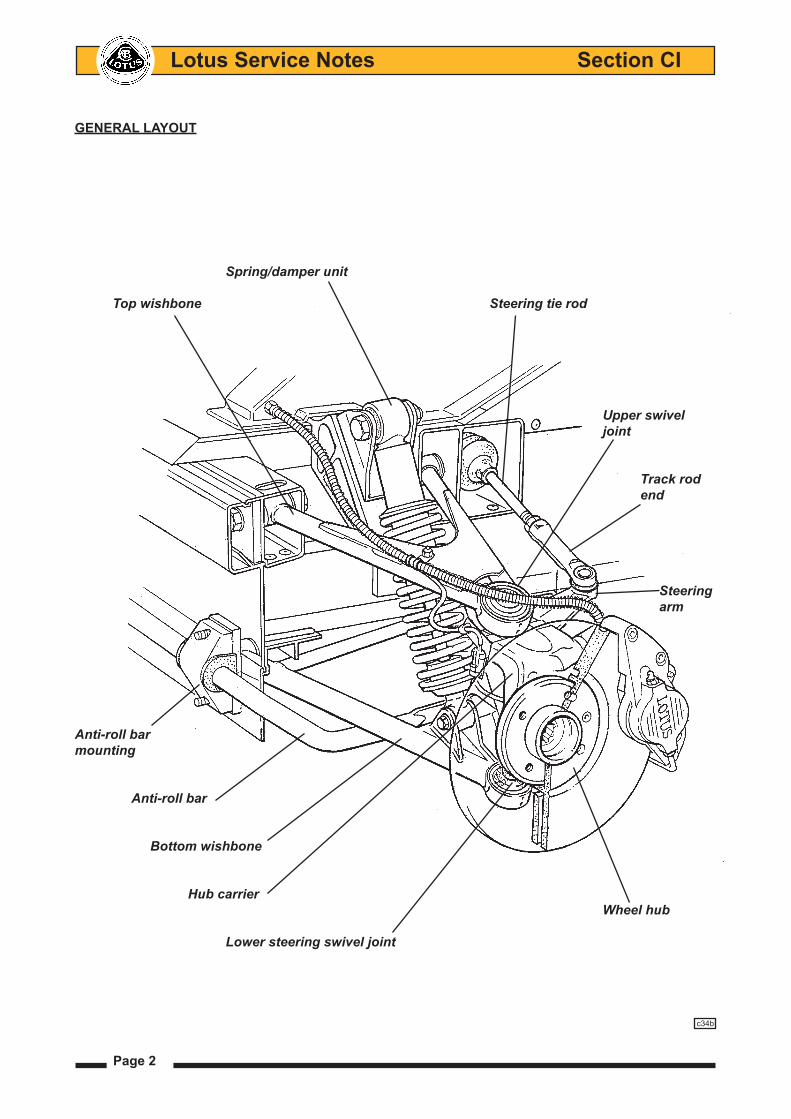
GENERAL LAYOUT
Spring/damper unit
Top wishbone Steering tie rod
Upper swivel joint
Track rod end
Steering arm
Anti-roll barmounting
Anti-roll bar
Bottom wishbone
Hub carrier Wheel hub Lower steering swivel joint
c34b

Page 3
Lotus Service Notes Section CI
CI.1 - GENERAL DESCRIPTION
The fully independent front suspension comprises, on each side of the car, upper and lower wishbones, a concentric coil spring/telescopic damper unit, and a tubular anti-roll bar. A forged steel hub carrier, provides a mounting for a the hub bearing unit to which the road wheel is attached via four spline socket bolts.
The upper and lower 'A' frame wishbones are fabricated from steel tube, the upper wishbone braced by sheet steel gussets at its apex, and the lower wishbone braced by a tubular strut at its base. The inboard ends of both wishbones use replaceable bonded rubber pivot bushes to provide maintenance free articulation, with a specification providing accurate and responsive dynamic characteristics. The outer ends of both wishbones incorporate housings into which the upper and lower steering swivel ball joints are pressed. The upper ball pin is secured to the forged steel, rearward facing steering arm, itself fixed to the hub carrier by two M10 bolts. The ball pin of the lower swivel joint is secured directly into a tapered hole in the bottom of the forged steel hub carrier. The Bilstein spring/damper unit acts between the outer end of the lower wishbone and the chassis, and is fitted with the damper rod lowermost in order to minimise unsprung weight.
A forward mounted tubular steel anti-roll bar, is supported in chassis mounted rubber or hard plastic pivot bushes and is operated via short ball jointed drop links from the lower wishbones.
CI.2 - GEOMETRY & ADJUSTMENTS
Provision is made for the adjustment of wheel alignment, camber and castor. Under normal service con-ditions, no periodic scheduled check of the geometry is necessary, although a front wheel alignment check is recommended when the front tyres are replaced. A full geometry check is required only after front suspension repair, or if excessive tyre wear is evident, or if steering difficulties are encountered. Before any measurements or adjustments are made it is essential first to set the vehicle to its ‘mid-laden’ ride height, approximating to driver and passenger and a half tank of fuel. This will require the vehicle to be ballasted, or tied down:
Standard EliseMid-laden ride height (reference height for geometry check);
- front 130 mm below front end of chassis siderail - rear 130 mm below rear end of chassis siderail Camber - optimum - 0.1° - tolerance + 0.1° to - 0.3°; Max side/side 0.2°Castor - optimum + 3.8° - tolerance + 3.5° to + 4.1°; max. side/side: 0.35°Alignment - optimum Zero - tolerance 0.5 mm toe-out to 0.7 mm toe-in overall (0.07° toe-out to 0.10° toe-in overall)Steering axis inclination 12° nominal
Ride height to be measured from the ground up to the chassis siderails at the lo-cation of the 'Jacking' point labels.
Updated 20th December 2010U
Page 4
Lotus Service Notes Section CI
Sport Elise, Exige Mid-laden ride height (reference height for geometry check);
- all except USA prior VIN 3013 - front 130 mm below front end of chassis siderail - rear 130 mm below rear end of chassis siderail
- USA prior VIN 3013 - front 135 mm below front end of chassis siderail - rear 135 mm below rear end of chassis siderail Camber - optimum - 0.3° - tolerance - 0.1° to - 0.5°; max. side/side: 0.2°Castor - optimum + 3.8° - tolerance + 3.5° to + 4.1°; max. side/side: 0.35°Alignment - optimum Zero - tolerance 0.5 mm toe-out to 0.5 mm toe-in overall (0.07° toe-out to 0.07° toe-in overall)Steering axis inclination 12° nominal
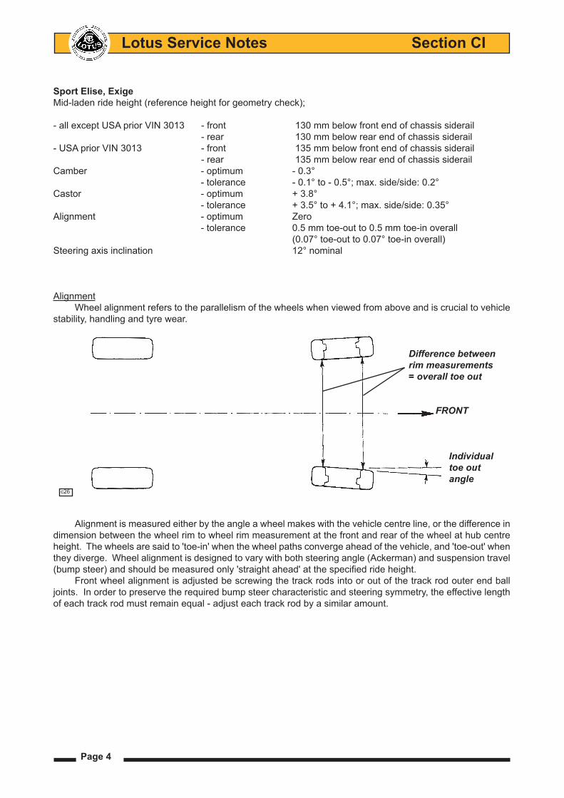
AlignmentWheel alignment refers to the parallelism of the wheels when viewed from above and is crucial to vehicle
stability, handling and tyre wear.
Alignment is measured either by the angle a wheel makes with the vehicle centre line, or the difference in dimension between the wheel rim to wheel rim measurement at the front and rear of the wheel at hub centre height. The wheels are said to 'toe-in' when the wheel paths converge ahead of the vehicle, and 'toe-out' when they diverge. Wheel alignment is designed to vary with both steering angle (Ackerman) and suspension travel (bump steer) and should be measured only 'straight ahead' at the specified ride height.
Front wheel alignment is adjusted be screwing the track rods into or out of the track rod outer end ball joints. In order to preserve the required bump steer characteristic and steering symmetry, the effective length of each track rod must remain equal - adjust each track rod by a similar amount.
Difference between rim measurements = overall toe out
FRONT
Individual toe out angle c26

Page 5
Lotus Service Notes Section CI
- Hold the track rod end using the flats provided, and slacken the locknut. Repeat for the opposite side.- Turn each track rod a similar amount. As a guide, turning both track rods by one quarter of a turn will alter
overall toe-out by approx. 2.0 mm.- When adjustment is correct, hold each track rod end and tighten the locknuts to 80 - 82 Nm (58 - 60 lbf.
ft).
When slackening or tightening the track rod end locknuts, it is important that the torque reaction is resisted using the track rod end flats, and that the ball joint itself is not allowed to be stressed. Camber Adjustment
Camber is the angle from vertical of the wheel when viewed from the front, and is said to be negative when the wheel leans inwards at the top (positive when leaning outwards). The primary purpose of camber is to achieve the maximum efficiency of the tyre under cornering loads and body roll, with the specification closely allied to a particular wheel/tyre combination. The camber angle changes with suspension travel, becoming more negative on bump, and should be measured only at the specified ride height. Incorrect camber can result in handling deficiencies and excessive tyre wear.
Camber adjustment is effected by adding or deleting shim plates between the steering arm (to which the upper steering swivel joint is fixed) and the hub carrier.
Camber angle
c29 Vertical Wheel centreline
Steering rack gaiter Trackrodendflats
Track rod end
Steering arm
Steeringtrackrodflats
Track rod end locknut c28a

Page 6
Lotus Service Notes Section CI
- Shimplates are available in 1mm and 3mm thicknesses.- Reducing the shim pack thickness will increase negative camber. Adding shims will reduce negative
camber.- A 1mm shim plate will alter camber by approximately 0.25°.- In March '04 the caphead bolts securing the ball joint plinth to the hub carrier were upgraded from 8.8 to
10.9 grade, with a corresponding increase in torque from 45 to 68 Nm. Before fitting these bolts, inspect the cap head for the grade marking, apply Permabond A130 (A912E7033) to the threads, and torque tighten to the appropriate figure.
Castor AdjustmentCastor is the angle from vertical of the steering axis of the wheel when viewed from the side. Its primary
purpose is to provide a natural straight running tendency of the steered wheels with forward vehicle motion. Castor angles have a complex interaction with other steering geometries and if unbalanced or outside of speci-fication, can result in various stability and handling deficiencies.
FRONT Top & bottom steering swivels
Castor angle c27
Camber adjustment shimplate
Steering arm
Hub carrier c30a
Page 7
Lotus Service Notes Section CI
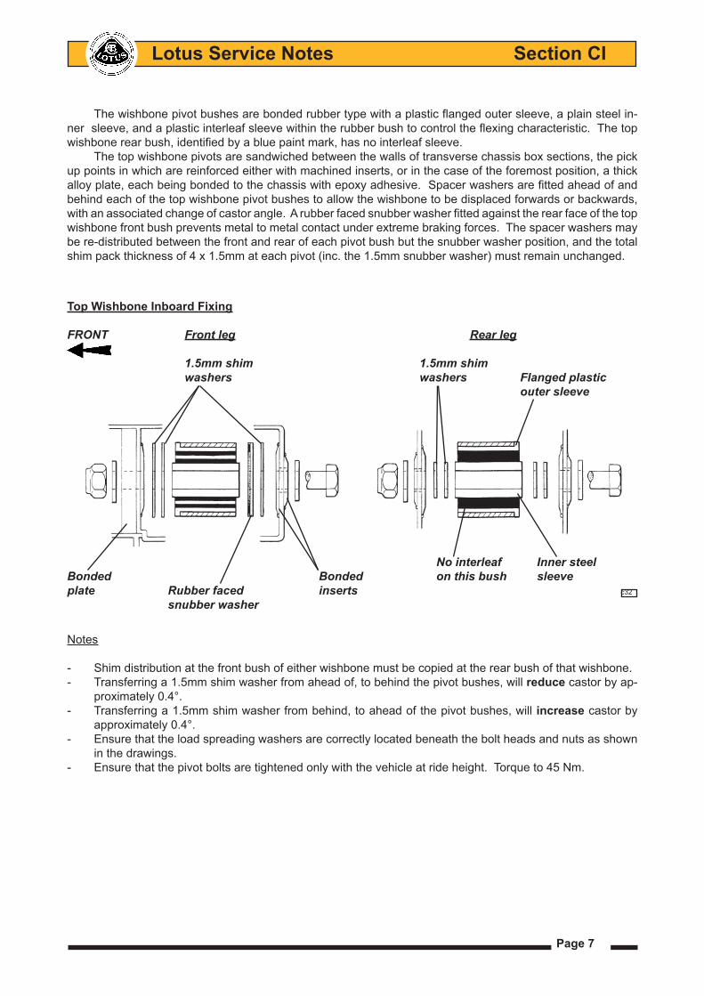
The wishbone pivot bushes are bonded rubber type with a plastic flanged outer sleeve, a plain steel in-ner sleeve, and a plastic interleaf sleeve within the rubber bush to control the flexing characteristic. The top wishbone rear bush, identified by a blue paint mark, has no interleaf sleeve.
The top wishbone pivots are sandwiched between the walls of transverse chassis box sections, the pick up points in which are reinforced either with machined inserts, or in the case of the foremost position, a thick alloy plate, each being bonded to the chassis with epoxy adhesive. Spacer washers are fitted ahead of and behind each of the top wishbone pivot bushes to allow the wishbone to be displaced forwards or backwards, with an associated change of castor angle. A rubber faced snubber washer fitted against the rear face of the top wishbone front bush prevents metal to metal contact under extreme braking forces. The spacer washers may be re-distributed between the front and rear of each pivot bush but the snubber washer position, and the total shim pack thickness of 4 x 1.5mm at each pivot (inc. the 1.5mm snubber washer) must remain unchanged.
Notes
- Shim distribution at the front bush of either wishbone must be copied at the rear bush of that wishbone.- Transferring a 1.5mm shim washer from ahead of, to behind the pivot bushes, will reduce castor by ap-
proximately 0.4°.- Transferring a 1.5mm shim washer from behind, to ahead of the pivot bushes, will increase castor by
approximately 0.4°.- Ensure that the load spreading washers are correctly located beneath the bolt heads and nuts as shown
in the drawings.- Ensure that the pivot bolts are tightened only with the vehicle at ride height. Torque to 45 Nm.
Top Wishbone Inboard Fixing
FRONT Front leg Rear leg
1.5mm shim 1.5mm shim washers washers Flanged plastic outer sleeve
No interleaf Inner steelBonded Bonded on this bush sleeveplate Rubber faced inserts c32
snubber washer

Page 8
Lotus Service Notes Section CI
CI.3 - ANTI-ROLL BAR
Three types of anti-roll bar and chassis mounting have been used:1. The standard tubular steel anti-roll bar is mounted in pivot bushes onto the front face of the chassis, and
is linked to the outboard ends of each lower front wishbone via short ball jointed links. The bar is mounted to the chassis using rubber pivot bushes for noise isolation, retained by alloy clamp brackets. Washers welded to the bar bear against the inner sides of the bushes to provide lateral location of the bar. Castrol LMX rubber grease, or equivalent, should be used when fitting the rubber bushes onto the anti-roll bar.
2. On Elise and Exige models built with 'Super Sport' suspension prior to August '06, a stiffer adjustable bar is used with 5 holes in each end to allow some adjustment of roll stiffness to be made. Standard setting is centre hole. Using a more forward hole increases stiffness. Two hard plastic clamping blocks secure the bar to the chassis via the front lower wishbone inboard front pivot bolts, with 'top hat' section steel spacers preventing the clamps from being crushed. An M5 bolt is used to close the bottom of each clamp.
These hard type mountings provide optimum steering response but will transmit more noise and require periodic lubrication with MoS2 grease at 3,000 mile (5,000 km) intervals. Noise from excessive clearance may be ameliorated by judicious shaving of the clamping block faces.
Anti-Roll Bar Mounting - Rubber Spacer plate Rubber mounting
Clamp bracket
c40
Anti-Roll Bar Mounting - Hard 1 'Top hat' spacer
Clamping block
M5 bolt
Lower wishbone pivot bolt Anti-roll bar c40a
Page 9
Lotus Service Notes Section CI
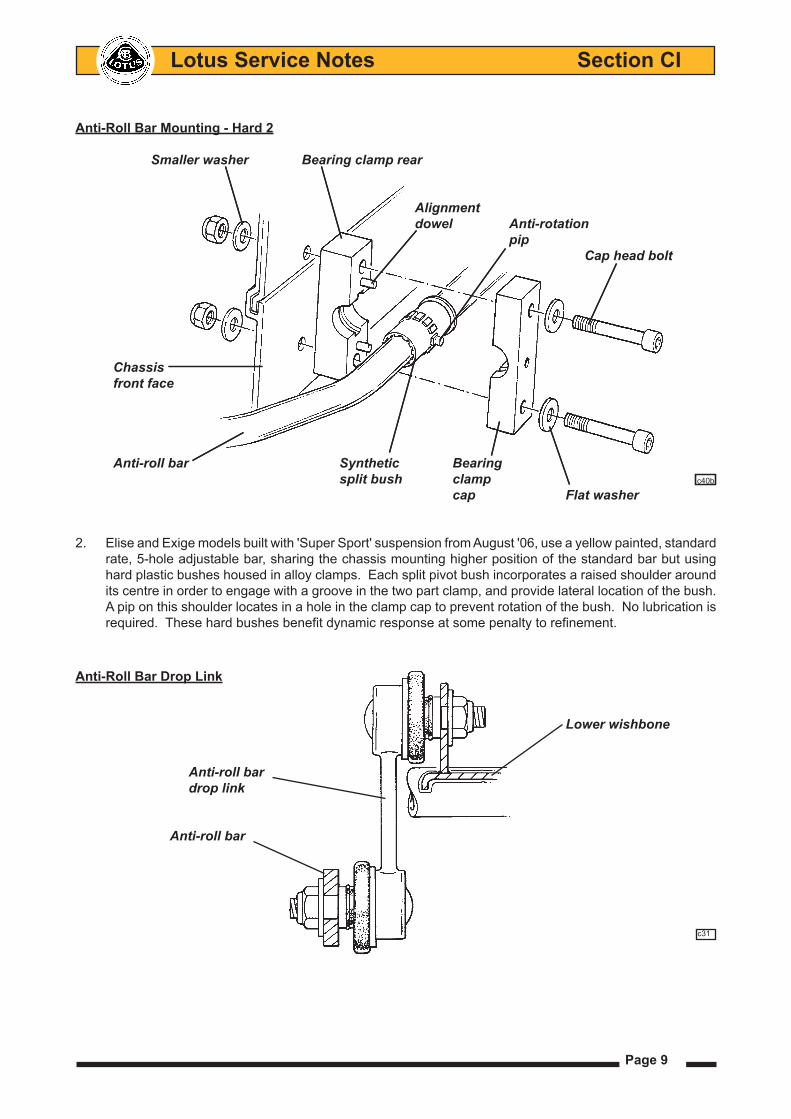
2. Elise and Exige models built with 'Super Sport' suspension from August '06, use a yellow painted, standard rate, 5-hole adjustable bar, sharing the chassis mounting higher position of the standard bar but using hard plastic bushes housed in alloy clamps. Each split pivot bush incorporates a raised shoulder around its centre in order to engage with a groove in the two part clamp, and provide lateral location of the bush. A pip on this shoulder locates in a hole in the clamp cap to prevent rotation of the bush. No lubrication is required. These hard bushes benefit dynamic response at some penalty to refinement.
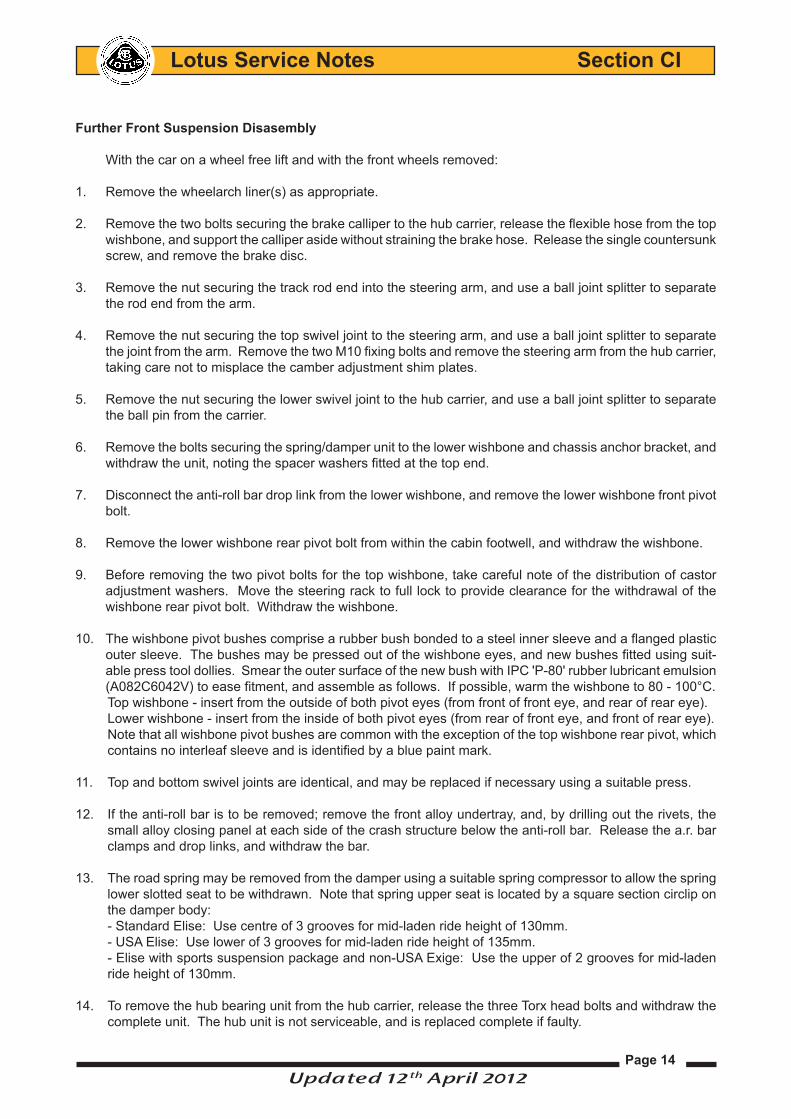
Anti-Roll Bar Drop Link
Lower wishbone
Anti-roll bar drop link
Anti-roll bar
c31
Anti-Roll Bar Mounting - Hard 2
Smaller washer Bearing clamp rear Alignment dowel Anti-rotation pip Cap head bolt
Chassis front face
Anti-roll bar Synthetic Bearing split bush clamp c40b
cap Flat washer

Page 10
Lotus Service Notes Section CI
CI.4 - SUSPENSION DISASSEMBLY/ASSEMBLY
The suspension may be disassembled without the use of any special tools other than a 'Torx' socket for the hub bearing carrier bolts, and a spring compressor, required only if the spring is to be removed from the damper unit.
Road spring damper assembly
The coil spring/telescopic damper units may be removed without causing disruption to the wishbone as-sembly mounting points or other suspension components.
Please note: Vehicles fitted with either Bilstein or Ohlins adjustable spring damper units incorporating remote reservoirs must be removed as complete assemblies. Never attempt to disconnect the reservoir from the damper assembly. Care must be taken to ensure that reservoirs and hoses are positioned and routed cor-rectly during re-assembly.
To remove
Raise and support vehicle.1. Remove road wheel.2. Remove the nut, bolt and washers securing the spring 3. and damper assembly to the lower wishbone. Remove the nut, bolt and washers securing the spring 4. and damper assembly to the chassis. Withdraw the spring assembly from the suspension.5.
To refit
Installation is the reverse procedure of removal
Refit upper and lower mounting bolts ensuring the bolts are -fitted through from front to rear of their mounting points so that the nyloc nuts are positioned to the rear of the mounting points. Torque both the upper and lower fixings to 45 Nm. -Refit road wheel, torque to 105 Nm. -
Note: Öhlins Damper (if fitted)
To remove
If the damper assembly also incorporates a re-mote reservoir then loosen the clips securing it to the front lower wishbone brace, detach the reservoir from the brace and withdraw the spring/damper and reservoir from the vehicle as one complete assembly.
See section DH.6 if vehicle fitted with Bilstein dampers with remote reservoirs.
Spring/damper
mounting bolts
Lower
wishbone
crossbracec63
RH remote reservior
viewed from underside
of vehicle
Reservoir
mounting
blocks
Reservoir
retaining clips
Updated 18 th June 2012U

Page 11
Lotus Service Notes Section CI
To refit
Installation is the reverse procedure of removal
Route the reservoir and its hose inbetween the rear of the upper wishbone and the steering rack tie rod, 1. then route the reservoir down to the lower wishbones crossbrace.Slide its two retaining clips around the two larger diameter sections of the reservoirs casing.2. Position the reservoir approximately centrally along the length of the wishbone brace. Fit the two rubber 3. mounting blocks in between the two larger diameter sections of the reservoir casing and the brace bar so that they are also in line with the retaining clips.Carry out the final positioning of the reservoir so that it's diameter is inline with the wishbones outer webbing/4. lower damper mounting platform.Fully tighten hose clips ensuring that their screw housings are positioned on top of the reservoir and the 5. hose leaves the reservoir in the horizontal plane.
Reservior hose routed in between upper wishbone and steering rack
Lower wishbone cross brace
Reservior located approximatelycentrally on thewishbone brace
c64
OHLINS ReMOTe ReSeRVIOR AND HOSe IN SITU (LHF)
Updated 12th April 2012U
Reservoir diameter is inline with the wishbones outer webbingof the lower damper mounting plat-form.

Page 12
Lotus Service Notes Section CI
Front Spring and Damper (Bilstein non-adjustable type)
Removal
Raise and support vehicle.1.
Remove road wheel.2.
Remove damper and spring assembly 3. (see previous operation).
Using suitable compression tools, 4. compress the road spring to relieve tension from retaining collar.
Push down bump stop and remove 5. slotted spring retaining collar.
Remove spring from damper.6.
Remove ‘C’ clip from damper (note 7. fitted position).
Remove spring collar from damper. 8.
Refitment
Refitment is the reversal of removal.
SUSPENSION
31-21
11
12
13
14
15
31
32
33
34
40
47
17
18
19
30
46
10
16
39
44
00FRT: 31032202
Damper - Rear - LH
Remove
1 Raise and support vehicle.
WARNING: Do not work on an incorrectly supported vehicle.
2 Remove road wheel (torque - 105 Nm).
3 Remove damper and spring assembly from vehicle. Refer to FRT: 31032102, page 31-20.
4 Compress spring.
WARNING: To avoid serious injury, use appropriate equipment to carry out this operation.
5 Move bump stop and remove slotted spring retaining collar.
6 Remove spring from damper.
7 Remove spring collar from damper.
8 Remove C-clip from damper (note fitted position).
CAUTION: Take care not to damage component(s).
NOTE: Always record quantity and fitted position of shims, washers, locktabs or clips.
Installation
1 Install procedure reverse of removal.
Compressroad spring
Slotted springcollar
Springcollar
'C' Clip
Updated 12th April 2012U

Page 13
Lotus Service Notes Section CI
Rear Spring and Damper (Ohlins adjustable with remove reservoir)
Removal
Remove the spring/damper/reservoir assembly from the vehi-1. cle, see operations above. (Note, it is not necessary to place the removed assembly in a vice but it is recommended to use a suitable clean workbench area).
Measure the distance between the underside of dampers 2. cylinder head and lower road spring lock nut and make a note of that measurement. (This will ensure that the vehicle’s ride height is same as before if a new spring or damper is fitted).
Loosen the lock nuts to relieve the pressure of off the road 3. spring.
Once the spring is no longer under compression i.e. it is lose 4. and free to move within the damper, remove the slotted col-lar from the stop washer (Located on the end of the damper rod).
The spring can now be withdrawn from the damper.5.
Spring refitment
Refitment is the reversal of removal; the road spring lock nuts should be wound up to compress the spring. Setting them to the same distance away from the dampers cylinder head as previously noted on its removal.
2/2 Issued 2011-09-20
STOP WASHER EXCHANGE TOOL KIT
1.5
1.10 2.1
1 Remove Stop Washer 03117-01 (Disassemble)1.1 Measure the distance between cylinder head and lock nut. See
1.2
1.3
1.4
1.5
1.6 Push the Bump rubber all the way down towards the Cylinder head.
1.7
1.8
1.9
turn counter clockwise.
1.10
plastic hammer.
2 Mount Stop Washer 03117-06 (Assemble)2.1
with a plastic hammer.
2.2 Clean the threads on the shaft.
2.3 Mount the End eye and Stop washer.
2.4Mount the Spacers in the End eye.
2.5 Adjust rebound. Set to the number of clicks noted in step 1.3 Disassemble.
2.6 Mount the spring. Set to noted measure in step 1.1 Disassemble.
2.7
2.8After replacing the Stop washer, mark the shock absorber in the
1.7
1.8
1.9
Measure
1.1 1.3
DamperCylinder head
Road springlock nuts
Note measurement if removing road spring
Remote reservoir hose
2/2 Issued 2011-09-20
STOP WASHER EXCHANGE TOOL KIT
1.5
1.10 2.1
1 Remove Stop Washer 03117-01 (Disassemble)1.1 Measure the distance between cylinder head and lock nut. See
1.2
1.3
1.4
1.5
1.6 Push the Bump rubber all the way down towards the Cylinder head.
1.7
1.8
1.9
turn counter clockwise.
1.10
plastic hammer.
2 Mount Stop Washer 03117-06 (Assemble)2.1
with a plastic hammer.
2.2 Clean the threads on the shaft.
2.3 Mount the End eye and Stop washer.
2.4Mount the Spacers in the End eye.
2.5 Adjust rebound. Set to the number of clicks noted in step 1.3 Disassemble.
2.6 Mount the spring. Set to noted measure in step 1.1 Disassemble.
2.7
2.8After replacing the Stop washer, mark the shock absorber in the
1.7
1.8
1.9
Measure
1.1 1.3
Slotted collar
Stopwasher
Reboundadjuster
Updated 12th April 2012U
Page 14
Lotus Service Notes Section CI
Further Front Suspension Disasembly
With the car on a wheel free lift and with the front wheels removed:
1. Remove the wheelarch liner(s) as appropriate.
2. Remove the two bolts securing the brake calliper to the hub carrier, release the flexible hose from the top wishbone, and support the calliper aside without straining the brake hose. Release the single countersunk screw, and remove the brake disc.
3. Remove the nut securing the track rod end into the steering arm, and use a ball joint splitter to separate the rod end from the arm.
4. Remove the nut securing the top swivel joint to the steering arm, and use a ball joint splitter to separate the joint from the arm. Remove the two M10 fixing bolts and remove the steering arm from the hub carrier, taking care not to misplace the camber adjustment shim plates.
5. Remove the nut securing the lower swivel joint to the hub carrier, and use a ball joint splitter to separate the ball pin from the carrier.
6. Remove the bolts securing the spring/damper unit to the lower wishbone and chassis anchor bracket, and withdraw the unit, noting the spacer washers fitted at the top end.
7. Disconnect the anti-roll bar drop link from the lower wishbone, and remove the lower wishbone front pivot bolt.
8. Remove the lower wishbone rear pivot bolt from within the cabin footwell, and withdraw the wishbone.
9. Before removing the two pivot bolts for the top wishbone, take careful note of the distribution of castor adjustment washers. Move the steering rack to full lock to provide clearance for the withdrawal of the wishbone rear pivot bolt. Withdraw the wishbone.
10. The wishbone pivot bushes comprise a rubber bush bonded to a steel inner sleeve and a flanged plastic outer sleeve. The bushes may be pressed out of the wishbone eyes, and new bushes fitted using suit-able press tool dollies. Smear the outer surface of the new bush with IPC 'P-80' rubber lubricant emulsion (A082C6042V) to ease fitment, and assemble as follows. If possible, warm the wishbone to 80 - 100°C.
Top wishbone - insert from the outside of both pivot eyes (from front of front eye, and rear of rear eye). Lower wishbone - insert from the inside of both pivot eyes (from rear of front eye, and front of rear eye). Note that all wishbone pivot bushes are common with the exception of the top wishbone rear pivot, which
contains no interleaf sleeve and is identified by a blue paint mark.
11. Top and bottom swivel joints are identical, and may be replaced if necessary using a suitable press.
12. If the anti-roll bar is to be removed; remove the front alloy undertray, and, by drilling out the rivets, the small alloy closing panel at each side of the crash structure below the anti-roll bar. Release the a.r. bar clamps and drop links, and withdraw the bar.
13. The road spring may be removed from the damper using a suitable spring compressor to allow the spring lower slotted seat to be withdrawn. Note that spring upper seat is located by a square section circlip on the damper body:
- Standard Elise: Use centre of 3 grooves for mid-laden ride height of 130mm. - USA Elise: Use lower of 3 grooves for mid-laden ride height of 135mm. - Elise with sports suspension package and non-USA Exige: Use the upper of 2 grooves for mid-laden
ride height of 130mm.
14. To remove the hub bearing unit from the hub carrier, release the three Torx head bolts and withdraw the complete unit. The hub unit is not serviceable, and is replaced complete if faulty.
Updated 12th April 2012U
Page 15
Lotus Service Notes Section CI
Reassembly Re-assemble the suspension in reverse order to disassembly with the following notes:- Take care to assemble each pivot bolt with the correct washers/snubbers/spacers as shown in the dia-
grams.- Smear the shank of each pivot bolt with PBC grease, but do not allow contamination of the threads.- Take care to refit the original camber adjustment shimpack, and distribute the castor shims as noted on
removal.- Top ball joint plinth fixing bolts: The bolts securing the steering arm/top ball joint plinth to the hub carrier were upgraded in March '04 at
VIN serial number 1537 (approx.) in order to commonise with motorsport applications. Earlier type 8.8 grade bolts should be tightened to 45 Nm; Later 10.9 grade bolts to 68 Nm. The bolt grade is stamped around the head of the bolt. The thread of both bolt types should first be treated with Permabond A130 (A912E7033V).
- After re-fitting a standard anti-roll bar, ensure that the crash structure closing panels are re-riveted.- Lubricate the rubber type anti-roll bar mountings with rubber grease and the Nylon type with MoS2
grease.- Apply Permabond A130 (A912E7033V) to the threads of the steering arm bolts.- Lubricate the ends of the damper top eye bush with rubber grease.- Press the brake pedal to reposition the pads before driving the car.- If the car suffers a suspension impact sufficient to damage a wheel rim, careful attention should be paid to
all related suspension components. Such forces can cause stretching of the lower ball pin and consequent fixing nut torque loss. As a safety precaution, it is recommended that in all such cases, the lower ball joint and the two bolts securing the upper ball joint plinth to the hub carrier are renewed.
The Service Schedule specifies that the security of the front and rear suspension is checked at each service. For cars used on race tracks, or in similar conditions, suspension components and torque checks should be carried out between sessions. This operation requires that all the principal suspension pivot bolts are torque checked, noting the following points:
Where a bolt is tapped into a housing or weldnut, and relies on a thread locking compound for security, it is important to appreciate that if the bolt is disturbed, the locking compound must be re-applied. The following procedure should be adopted for all such fixings:- Check the torque of the fixing. - If the specified torque is attained without the fixing being disturbed (moving), take no further action.- If the bolt moves, the locking action of the thread adhesive will have been compromised. Remove the
bolt completely, clean off all old adhesive using a wire brush and acetone, and apply new adhesive as specified.
- Refit the bolt and tighten to the specified torque.- If for any reason a bolt is found to have become loose, and the car has been operated for any period in
this condition, the bolt should be renewed as a standard precaution and related components carefully inspected for hole ovality or wear.
Torque Settings: NmUpper and lower wishbone pivot bolts 45Upper swivel joint to steering arm 55Lower swivel joint to plinth 55Steering arm to hub carrier - 8.8 grade 45 - 10.9 grade 68Track rod end to steering arm 30Damper to lower wishbone 45Damper to top anchor bracket 45Damper anchor bracket to chassis 25Hub bearing unit to hub carrier 90Brake calliper to hub carrier 45Anti-roll bar alloy mounting clamps 25Anti-roll bar drop links 45
Updated 12th April 2012U

Page 16
Lotus Service Notes Section CI
CI.5 - FRONT WHEEL BEARINGS
The sealed front wheel bearings are contained in a steel housing secured to the hub carrier with three 'Torx' bolts. The double row, angular contact, ball bearing is retained in the outer housing and also onto the hub spigot by a shoulder and a peening operation, and is inseparable for service. Note that all four hub as-semblies are common, and incorporate a wheel speed sensor in the bearing unit, with a flying lead terminating in an electrical connector plug secured by a camber shim plate bracket.
If there is found to be any discernible free play in the hub bearing, or any roughness or tight spots can be felt, or any signs of lubricant expulsion are evident, the hub assembly should be replaced - there is no provi-sion for adjustment.
To Replace Hub Bearing Assembly1. With the wheel removed, release the two fixing bolts, and remove the brake calliper from the hub carrier.
Support clear of the brake disc without straining the flexible hose. Release the single countersunk screw and withdraw the brake disc from the hub.
2. Using a Torx socket, release the three bolts securing the hub bearing unit to the hub carrier.
3. Fit the new hub bearing unit to the hub carrier and retain with the three Torx bolts. Torque tighten to 90 Nm.
4. Refit the brake disc and calliper, using Permabond A130 (A912E7033) to the threads of the calliper fixing bolts and torque tightening to 45 Nm. Pump the brake pedal to reposition the pads before driving the car.
Steering arm
Hub carrier
Hub Hubtocarrierfixingbolt
Swaged bearing retention
c41a
Double row ball bearing
Steering arm
Hub carrier
Hub Hubtocarrierfixingbolt
Swaged bearing retention
c41a
Double row ball bearing
Updated 12th April 2012U