los alamos alamos national labs...los alamos field office, a316 3747 west jemez road los alamos, new...
TRANSCRIPT
~ " Los Alamos
NATIONAL LABORATORY --- EST 1943 ----
Environmental Protection and Compliance Division Environmental Compliance Programs (EPC-CP) PO Box 1663, K490
·Los Alamos, New Mexico 87545 (505) 667-0666
Date:: Symbol: LA-UR:
Locates Action No.:
Mr. John E. Kieling Hazardous Waste Bureau New Mexico Environment Department 2905 Rodeo Park Drive East, Building 1 Santa Fe, NM 87505
Dear Mr. Kieling:
National Nuclear Security Administration Los Alamos Field Office, A316 3747 West Jemez Road Los Alamos, New Mexico, 87544 (505) 665-7314/Fax (505) 667-5948
Subject: Transmittal of Class 1 Permit Modification Request to Remove Structure TA-55-PF-190 from the Los Alamos National Laborat.ory (LANL) Hazardous Waste Facility Permit, EPA ID No. NM0890010515
The purpose of this letter is to submit a Class 1 permit modification request to remove one mobile structure located on the TA-55-4 Outdoor Container Storage Pad (TA-.S5-4 Outdoor Storage Pad) from the Los Alamos National Laboratory (LANL) Hazardous Waste Facility Permit issued to the Department of Energy and Los Alamos National Security, LLC (the Permittees) in November 2010. The permit modification request provides proposed revisions to Permit Attachments A, G.26, J and N.
The proposed modifications have been prepared in accordance with the Code of Federal Regulations [CFR], Title 40 (40 CFR) § 270.42(a) as a permit modification requiring New Mexico Environment Department Hazardous Waste Bureau (NMED-HWB) approval. This Class 1 permit modification request consists solely of administrative changes in accordance with 40 CFR § 270.42, Appendix 1, Item A. I and Permit Section 3 .1 (3). Permit Section 3.1 (3) requires that all figures accurately reflect the location of all buildings and structures, regardless of whether they manage hazardous waste.
Included in this permit modification request package are the transmittal letter, a signed certification page, a signed affidavit and one enclosure. Enclosure 1 provides a description of the proposed changes and pages ofrevised text and/or Figures from Attachments A, G.26, J and N.
., Included herein are three hard copies and one electronic copy of this submittal. The hardcopy submittal contains pages or sections where text has been changed, rather than copies of the entire collection of Permit
37694 An Equal Opportunity Employer I Operated by Los Alamos National Security, LLC for the U.S. Department of Energ:
I 1111111111111111111111111111111111

Mr. John E. Kieling EPC-D0-16-221
- 2 -
attachments. The electronic copy, provided only to the New Mexico Environment Department Hazardous Waste Bureau (NMED-HWB), contains a reproduction of the hardcopy in portable document format (PDF) along with all the word processing files used to create the hardcopy.
Upon approval by the NMED-HWB, this permit modification will be sent to the NMED-HWB maintained LANL facility mailing list in accordance with 40 CFR § 270.42(a)(l)(ii) within ninety days of the transmittal of this permit modification request.
If you have comments or questions regarding this permit modification request, please contact Karen E. Armijo (DOE) at (505) 665-7314 or Mark Haagenstad (LANS) at (505) 665-2014.
Sincerely,
Division Leader Environmental Protection and Compliance Division Los Alamos National Security, LLC
JCB :KEA:MPH:SDG/lm
Sincerely,
Karen E. Armijo Permitting and Compliance Program Manager
National Nuclear Security Administration Los Alamos Field Office U.S. Department of Energy
Enclosure: 1) Class 1 Permit Modification Request for Removal ofTA-55-PF-190 Structure from Technical Area (TA)-55 Building 4 Outdoor Container Storage Pad (TA-55-4 Outdoor Pad)
Cy: Laurie King, USEPA/Region 6, Dallas, TX (E-File) Kathryn M. Roberts, NMED/HWB, Santa Fe, NM, (E-File) Dave Cobrain, NMED/HWB, Santa Fe, NM, (E-File) Neelam Dhawan, NMED/HWB, Santa Fe, NM, (E-File) Siona Briley, NMED/HWB, Santa Fe, NM (E-File) Kimberly Davis Lebak, NA-LA, (E-File) Peter Maggiore, NA-LA, (E-File) Karen E. Armijo, NA-LA, E-File) Jody M. Pugh, NA-LA, (E-File) Craig S. Leasure, PADOPS, (E-File) William R. Mairson, PADOPS, (E-File) Michael T. Brandt, ADESH, (E-File) Raeanna Sharp-Geiger, ADESH, (E-File) Keith Lacy, NPI-7, (E-File) Joseph A. Gonzales NPI-7, (E-File)
An Equal Opportunity Employer I Operated by Los Alamos National Security, LLC for the U.S. Department of Energy's

Mr. John E. Kieling EPC-D0-16-221
Cy (continued): Mark P. Haagenstad, EPC-CP, (E-File) Shanon Goldberg, EPC-CP, (E-File) Jeff Carmichael, EPC-CP, (E-File) Patrick Padilla, EPC-CP, (E-File) Ellena I. Martinez, EPC-CP, (E-File) [email protected], (E-File) [email protected], (E-File) [email protected], (E-File) [email protected], (E-File)
- 3 -
An Equal Opportunity Employer I Operated by Los Alamos National Security, LLC for the U.S. Department of Energy's

Document: LANL Class I Permit Modification Date: September 2016
CERTIFICATION
I certify under penalty of law that this document and all attachments were prepared under my direction or supervision in accordance with a system designed to assure that qualified personnel properly gather and evaluate the information submitted. Based on my inquiry of the person or persons who manage the system, or those persons directly responsible for gathering the information, the information submitted is, to the best of my knowledge and belief, true, accurate, and complete. I am aware that there are significant penalties for submitting false information, including the possibility of fine and imprisonment for knowing violations.
Division Leader Environmental Protection and Compliance Division
Los Alamos National Security, LLC
Operator
Karen E. Armijo Permitting and Comp iance Program Manager
National Nuclear Security Administration Los Alamos Field Office
U.S. Department of Energy Owner/Operator
Page 1
9-/i-/6
Date Signed
Date Signed
LA-UR-16-26002

AFFIDAVIT
1. I, Keith A. Lacy, am an employee of Los Alamos National Security, LLC, at Los Alamos National Laboratory (LANL) and have been employed at LANL for 18 years.
2. I am the Group Leader of the Nuclear Process Infrastructure, Hazardous Materials Management group and oversaw hazardous and mixed low-level waste management operations at TA-55 since 2014.
3. The information in this affidavit reflects my personal knowledge of the TA-55-PF-190 container storage building, as well as information provided to me by the employees who undertake waste management operations at TA-55.
4. TA-55-PF-190 is a structure that contains a less than 90-day hazardous waste accumulation area. The TA-55-PF-190 structure is currently located within the boundary of the TA-55 Container Storage Pad permitted unit.The building stored and supported waste management activities associated with the less than 90-day hazardous waste accumulation area and has also served as a universal waste storage area. Building TA-55-PF-190 has never received waste from any permitted unit.
5. TA-55-PF-190 has been in use since May 29, 2015. Review of inspection records and interviews with NPl-7 personnel reveal no hazardous waste spills or releases has occurred in association with waste management activities at building TA-55-PF-190.
6. TA-55-PF-190 will be moved outside of the TA-55 Container Storage Pad and will continue to be used as less than 90-day hazardous waste accumulation area. The building will not be located within a permitted unit boundary.
FURTHER AFFIANT SAYETH NAUGHT.
STATE OF NEW MEXICO )ss.
COUNTY OF LOS ALAMOS
SUBSCRIBED, SWORN TO AND ACKNOWLEDGE before me this / dfh day of
~ I 2016 by bOUt:l \6\ 1:). {Y\J:6;'n°'-.
NOTARY PUBLIC
My Commission Expires:
sJs)aotq


Los Alamos National Laboratory Hazardous Waste Permit
January 2016
2
TABLE OF CONTENTS
A.1 TA-3 4
A.1.1 TA-3 Building 29 4
A.1.2 Security and Access 5
A.1.3 Emergency Equipment 5
A.2 RESERVED 6
A.3 TA-50 6
A.3.1 TA-50-69 Indoor Permitted Unit 7
A.3.2 TA-50-69 Outdoor Permitted Unit 7
A.3.3 Security and Access 7
A.4 TA-54 9
A.4.1 AREA L 10
A.4.2 AREA G 14
A.4.3 TA-54 West 21
A.4.4 Security and Access Control 23
A.4.5 Emergency Equipment 24
A.4.6 Preventing Run-on and Runoff 26
A.5 TA-55 27
A.5.1 B40 28
A.5.2 B05 28
A.5.3 K13 28
A.5.4 B45 28
A.5.5 Vault 28
A.5.6 Outdoor Storage Pad 29
A.5.7 Mixed Waste Storage Tank System 29
A.5.8 Mixed Waste Stabilization Unit 33
A.5.9 Security and Access Control 35
A.5.10 Emergency Equipment 36
A.6 TA-63 TRANSURANIC WASTE FACILITY 36
A.6.1 Concrete Pad 38
A.6.2 Storage Buildings 38

Los Alamos National Laboratory Hazardous Waste Permit
January 2016
3
A.6.3 Storage and Characterization Building 39
A.6.4 Characterization Trailers 39
A.6.5 Retention Basin 41
A.6.6 Other Project Structures 41
A.6.7 Security and Access Control 42
A.6.8 Required Equipment 42
A.6.9 Control of Run-on/Run-off 44
A.6.10 Subsurface Vapor Monitoring 44

Los Alamos National Laboratory Hazardous Waste Permit
January 2016
4
ATTACHMENT A
This attachment contains TA-specific unit descriptions, including the dimensions, materials of construction, security procedures, and emergency equipment of each unit provided by the Permittees in their permit application.
A.1 TA-3
TA-3 is located in the northern portion of the Facility on South Mesa between Los Alamos Canyon on the north and Two Mile Canyon on the south. Sandia and Mortandad Canyons head on the east margin of TA-3 forming steep cliffs at the top of canyon walls.
A.1.1 TA-3 Building 29
TA-3-29, the Chemistry Metallurgy Research Building (CMR), was established in 1952 as a research facility (see Figure 12 in Permit Attachment N (Figures)). It is a three story structure containing offices, laboratories, and one permitted container storage unit located in the basement at TA-3 building 29 of Wing 9. The TA-3-29 permitted unit consists of a room (9010) and portions of two other rooms (9020 and 9030) where storage of hazardous and mixed waste occurs. The following provides a description of the permitted unit.
A.1.1.1 TA-3-29 Room 9010
Room 9010 measures 21 feet by 8 inches wide by 106 feet, 9 inches (in) long (see Figure 13 in Permit Attachment N (Figures)). The floor is concrete and is painted with an epoxy sealant. Waste storage takes place in the lower level portion of Room 9010 but may also take place in or near the two room enclosures 9010A and 9010B.
The northern enclosure is approximately 10 ft wide by 24 ft long; the southern enclosure measures approximately 17 ft wide by 54 ft long. The enclosures have ceilings, walls with windows, and doors for entry through airlocks; the enclosures are anchored to the floor. The wall to floor joints are sealed with grout. Floors and the lower six inches of the interior enclosure walls are coated with an epoxy sealant. Each enclosure includes emergency and communication equipment as well as ventilation, fire sprinkler, water, and electrical support functions connected to the main building systems. The enclosures are kept at negative pressure by the building’s exhaust system via exhaust ports in the enclosures which are ducted through high-efficiency particulate air filters to provide radioactive material air release protection.
A.1.1.2 TA-3-29 Portion of Room 9020
Room 9020 is approximately 27 feet wide by 141 feet long. The permitted container storage area measures 19 feet wide by 25 feet long (see Figure 14 in Permit Attachment N (Figures)) and is located in the northeast side of the room. The floor is concrete and painted with an epoxy sealant.

Los Alamos National Laboratory Hazardous Waste Permit
January 2016
5
A.1.1.3 TA-3-29 Portion of Room 9030
Room 9030 is approximately 62 feet wide by 141 feet long. The permitted container storage area within Room 9030 measures approximately 30 feet long by 8 feet wide (see Figure 15 in Permit Attachment N (Figures)) and is located in the southwest corner of the room. The floor is concrete and has been painted with an epoxy sealant. Hand trucks, dollies, or casters will be used to move waste containers from the loading area to the storage portions of the permitted unit. Should a spill occur during waste handling activities, management of the spill and residual material will be performed in accordance with Attachment D (Contingency Plan). Drums on dollies will be moved manually and a pallet jack will be used to move standard waste boxes.
A.1.2 Security and Access
Security at TA-3-29 is maintained with physical and administratively-controlled barriers. These barriers prevent the unknowing entry and minimize the possibility for unauthorized entry of persons or livestock into the areas. Eight-foot-high chain-link security fences with barbed wire at the top surround the entire perimeter of the building. Bilingual (i.e., English and Spanish) warning signs are also posted at the entrances to each portion of the permitted unit within the building and can be seen from any approach to these locations. The legends on the signs indicate "Danger: Hazardous Waste Storage Area" and "Unauthorized Persons Keep Out." The signs are legible from a distance of at least 25 ft. There are four entry gates through the security fence at TA-3-29 (see Figure 4 in Permit Attachment N (Figures)). A fire access and shipping gate is located south of TA-3-29 and is routinely closed and locked. When the gate is opened for shipments of material or waste, personnel are present at the gate to restrict the entry and exit of unauthorized persons. The northwest entrance is an open gate which allows vehicular and pedestrian entry. Access is controlled through a manned gate at the western entrance to the TA-3 Security Area. Another unmanned badge reader entry pedestrian gate is located at the southeast corner of the building‘s fence line. This gate is combined with a double vehicular gate which allows access from the parking area south of the building. Security personnel are present at each of these gates during operational hours to restrict the entry and exit of unauthorized persons. Outside doors to the main wings of TA-3-29 are always locked. Access for visitors to the operational portion of the building is controlled by turnstiles located in the east side lobby and another on the west side of the building. Roll-up doors to the building can only be opened from inside the building and are also locked; opening these doors must be coordinated with security personnel. The building site is patrolled by security personnel during nonoperational hours to ensure that the gates are locked and that unauthorized entry has not occurred.
A.1.3 Emergency Equipment
TA-3-29 is equipped with an audible alarm system to alert personnel to evacuate the area. The evacuation alarm system may be activated by facility personnel pushing one of the evacuation buttons located throughout TA-3-29. The building also contains a fire alarm system which may be activated by manual pull stations, heat and smoke detectors, and sprinkler system flow valves found throughout TA-3-29. Rooms 9010, 9020, and 9030 contain wet-pipe sprinkler systems that are equipped with fusible-link heads that actuate at 212 degrees Fahrenheit.

Los Alamos National Laboratory Hazardous Waste Permit
January 2016
6
Wing 9 of TA-3-29 contains gamma alarms that monitor for the presence of gamma radioactive contamination. Continuous air monitors are utilized throughout TA-3-29 to detect airborne radioactive contamination and, when detected, sound an alarm. The building also has a public address system for announcing fires or evacuations. Telephones with paging capabilities are located throughout TA-3-29. Paging telephones are used to page on-site personnel and may be used in the event of an emergency to communicate the location and nature of hazardous conditions to personnel in the area. Personnel working in Rooms 9010, 9020, and 9030 can also use these phones to summons assistance from local emergency response teams in case of emergency. Rooms 9010, 9020, and 9030 are equipped with fire extinguishers and pull stations. Depending on the size of a fire and the fuel source, fire extinguishers may be used by on-site personnel. However, the Facility policy encourages immediate evacuation of the area and notification of appropriate emergency personnel. The fire alarm control panel continuously monitors all fire-suppression and detection systems and transmits signals to the Los Alamos Fire Department through the Facility’s central alarm system.
Fire hydrants installed according to National Fire Protection Association standards are located around the outside of TA-3-29. Water is supplied to the fire hydrants by a municipal water system through 8-in. pipes at an adequate volume and pressure (i.e., 200 gallons per minute and 90 pounds per square inch static pressure) to supply a water hose in the event of a fire. Spill kits, which contain sorbent pillows, safety glasses, and gloves, are located at the south end of Room 9010 in enclosures 9010a and 9010b. Trained personnel may use this equipment to mitigate small containable spills when they are certain their actions will not put themselves or others at risk. Available personnel decontamination equipment includes safety showers and emergency eyewashes in enclosures 9010a and 9010b.
Personnel working in Room 9020 have access to the eyewashes in enclosures 9010a and 9010b and a safety shower and emergency eyewash in Room 9030. The buddy system will always be employed when containers are actively managed in Rooms 9010, 9020, and 9030 to assure that safety showers and eyewashes can be reached in an emergency. Safety Data Sheets (SDS) (formerly Material Safety Data Sheets (MSDS)) provide useful exposure information and are available in Rooms 9010, Room 9030, and outside Room 9030.
A.2 RESERVED
A.3 TA-50
TA-50 is located at the northeast corner of the intersection of Pajarito Drive and Pecos Road, on the finger mesa bounded by Mortandad Canyon to the north and Two-Mile Canyon to the south (see Figure 22 in Attachment N (Figures)). The container storage units at TA-50 include the TA-50-69 Indoor unit (Rooms 102 and 103) and the TA-50-69 Outdoor unit.
The northern and eastern portions of TA-50 drain mainly to an unlined channel on the boundary between TA-50 and TA-35 (east of TA-50), although some flow diverges into a shallow channel running southward between TA-50-37 and TA-50-1.

Los Alamos National Laboratory Hazardous Waste Permit
January 2016
7
A.3.1 TA-50-69 Indoor Permitted Unit
The TA-50-69 Indoor permitted unit consists of Rooms 102 and 103 as shown in Figure 23 in Attachment N (Figures). Room 102, the main process room, measures approximately 45 feet wide and 52 feet long. Room 103, the unloading area, measures approximately 18 feet wide and 19 feet long and is located adjacent to and southeast of Room 102. A 12 foot by 20-foot roll-up vehicle access door is located at the southernmost end of Room 103 separating the unloading area (Room 103) from the vehicle airlock entrance (Room 104). This design allows for unobstructed transport of oversized fiberglass-reinforced plywood boxes from outside the facility, through the vehicle airlock entrance, into the unloading area, and into the glove box cutting enclosure.
A.3.2 TA-50-69 Outdoor Permitted Unit
The TA-50-69 Outdoor permitted unit was constructed before 1980 and was first used to store mixed waste in 1982. It is located in the southwest corner of TA-50 (see Figure 23 in Attachment N (Figures)). The TA-50-69 Outdoor unit is comprised of an unlined and non-coated asphalt pad measuring 24 feet in width and 90 feet in length. The entire pad is approximately 4 inches thick and slopes gently (approximately one to five percent) from west to east and up to 2.5 percent toward the centerline. Transportainers and other weather protective structures (i.e., containers covered with tarps, containers inside SWBs) in the permitted unit provide weather protection for containers of various sizes. Painted lines are used to visually delineate the TA-50-69 Outdoor unit boundary. Drainage swales located in the vicinity divert storm water away from the pad. One drainage swale is located just south of the unit; between it and the material disposal area C. A second drainage swale is located on the west side of the permitted unit between Pecos Drive and the TA-50 fence line.
A.3.3 Security and Access
Security at TA-50 is predominantly maintained with artificial barriers. These barriers prevent the unknowing entry and minimize the possibility for unauthorized entry of persons or livestock into the area.
An 8ft high chain-link security fence surrounds the entire perimeter of TA-50. Bilingual (i.e., English and Spanish) warning signs are posted on the fences at approximately 50 to 75 foot intervals. Warning signs are also posted at the entrances to each area that will manage hazardous and mixed waste and are visible from any approach to these areas. The legends on the posted signs indicate “Danger-Hazardous Waste Storage Area” and “Unauthorized Persons Keep Out.” Existing signs with a legend other than ”Danger-Unauthorized Persons Keep Out” may be used if the legend on the sign indicates that only authorized personnel are allowed to enter the active portion, and that entry into the active portion can be dangerous. The signs are legible from a distance of 25 ft. Additionally, signs are posted at the entrance to each hazardous and mixed waste permitted unit to address requirements associated with entering and working in the area.
There are four entry gates into TA-50. Two entry gates are located north of TA-50-1. During normal business hours, the easternmost of these two gates may remain open to receive
Los Alamos National Laboratory Hazardous Waste Permit
January 2016
8
deliveries. After normal business hours, this gate is padlocked. The westernmost of these two gates is the main access gate and remains open during normal business hours for personal and government-owned passenger vehicles. After normal business hours, access through this gate is by badge-reader only. The third gate is a fire access and shipping gate which is located west of TA-50-69 and is routinely kept closed and locked. When this gate is opened for shipments of materials or waste, facility personnel are present in the yard west of TA-50-69 to limit entry by unauthorized persons. When shipments are completed, the gate is re-closed and locked. A fourth gate to the south of TA-50-1 is locked except when authorized access is necessary.
TA-50-69 is located in the southwest quadrant of TA-50. The TA-50-69 Indoor unit was constructed in 1979 to house the Waste Characterization, Reduction, and Repackaging Facility (WCRRF). The primary purpose of WCRRF was to size reduce and repackage large transuranic contaminated metallic items (e.g., glove boxes, process equipment) into standard sized containers for transport to, and disposal at, the Waste Isolation Pilot Plant. The facility was first used to size reduce mixed transuranic waste in 1982. The original function of the WCRRF has since been expanded to include other activities related to hazardous and mixed waste management including waste characterization, transuranic and mixed transuranic waste prohibited item disposition and repackaging operations, and experimental process demonstration support.
TA-50-69 is a single-story building constructed in two phases. The original structure (45ft by 52 ft) was built in 1979 to house the main process room (Room 102) and personnel change rooms. An unloading area (Room 103), a vehicle airlock entrance (Room 104), and a mezzanine over the western third of the main process room were added to the building in 1986.
The exterior walls of TA-50-69 are load-bearing and constructed of structural steel framing with a plastic veneer finish on polystyrene insulation and gypsum wallboard. The interior walls are similarly constructed. The epoxy-painted floor of the building is a reinforced concrete slab on compacted fill.
A forklift will be used to move containers stored at the permitted units at TA-50-69. Fiberglass-reinforced plywood boxes and palletized drums will be handled with a forklift equipped with tines. Individual drums of waste will be manipulated with a drum-grapple attachment on the forklift. Small containers may be handled manually or with a dolly. Inside TA-50-69 two cranes are available to move heavy objects.
TA-50 is patrolled by security personnel during non-operational hours to ensure that unauthorized entry has not occurred. The locations of the security fences and entry gates at TA-50 are shown on Figure 6 in Permit Attachment N (Figures).
TA-50-69 access is controlled through a centralized Operations Center located in TA-50-84. The Indoor permitted unit is always locked and access is gained by a badge reader. Doors to the building and transportainers are locked. Keys to these doors are distributed to designated personnel only. A chain is installed at the east end of the operations area and adjacent to TA-50-84 and is posted with the bilingual hazardous waste sign.

Los Alamos National Laboratory Hazardous Waste Permit
January 2016
9
All personnel involved in waste management activities at the TA-50-69 indoor and outdoor permitted units have immediate access to an internal alarm or emergency communication device. In the event of an emergency, this communication equipment allows personnel to contact the operating group management, the Emergency Management and Response personnel, or the Central Alarm Station operator.
TA-50-69 is equipped with an audible alarm system to alert personnel to evacuate the area. The alarm system may be activated by one of the fire alarm pull stations located throughout the building. Personnel can also use phones to summon assistance from local emergency response teams in case of an emergency. Personnel may carry pagers, two-way radios, or cellular telephones so they can contact, or be contacted by, on-site and the Facility emergency support personnel at all times.
TA-50-69 is equipped with fire extinguishers and fire suppression systems. Depending on the size of a fire and the fuel source, fire extinguishers may be used by on-site personnel. However, the Facility policy encourages immediate evacuation of the area and notification of appropriate emergency personnel. The fire alarm control panel continuously monitors all fire suppression and detection systems and transmits signals to the Los Alamos County Fire Department through the Facility’s central alarm system.
A fire hydrant installed according to National Fire Protection Association standards is located approximately 55 feet west of TA-50-69. Water is supplied to the fire hydrant by a municipal water system through eight inch pipes at an adequate volume and pressure (i.e., 200 gallons per minute and 90 pounds per square inch static pressure) to supply a water hose in the event of a fire.
TA-50-69 has an automatic wet-pipe sprinkler system in the main building and in the large glove box enclosure. The sprinkler system is heat-activated at 100°C (212°F). The TA-50-69 Outdoor permitted unit transportainers and weather protective structures are not equipped with automatic sprinkler systems; however, a fire extinguisher is located within 20 feet of the unit. Personnel may use the fire alarm pull station at TA-50-69 in the event of a fire at both the indoor and the outdoor permitted units.
Two spill centers are located in TA-50-69 Room 102. They contain spill control equipment, personal protective equipment, and sorbents. Trained personnel may use this equipment to mitigate small containable spills when they are certain their actions will not put themselves or others at risk. Depending on the size and severity of the spill, EM&R provides additional spill control equipment and assistance upon request. Available personnel decontamination equipment includes safety showers and eye wash stations located in the TA-50-69 indoor permitted unit.
A.4 TA-54
TA-54 consists of 130 acres atop Mesita del Buey and is used for storage of hazardous and mixed waste generated throughout the Facility (see Figure 24 in Attachment N (Figures)). A principal mission of TA-54 is to manage Facility waste safely and efficiently, consistent with

Los Alamos National Laboratory Hazardous Waste Permit
January 2016
10
federal and state regulations and U.S. Department of Energy (DOE) requirements. TA-54 has three separate areas where hazardous and mixed waste is stored; Area L, Area G, and TA-54 West (see Figure 25 in Attachment N (Figures)). There is one permitted unit at Area L, nine permitted units at Area G, and two permitted units at TA-54 West (see Attachment J (Hazardous Waste Management Units)).
Waste containers are transported to the permitted units at Areas L, G, and West by flatbed trucks, closed-box trucks, or trailers. The permitted units have design features that promote safe unloading and handling of waste containers from these trucks and trailers. Ramps are typically located at vehicle entrances to the dome structures at the Area L and Area G permitted units. Shed 31 at Area L and Shed 8 at Area G have sloped entryways for container-handling equipment. The storage domes have roll-up or roll-away vehicle access doors. The loading dock at TA-54 West allows access from the transport vehicles to the loading dock platform. These design features facilitate safe handling of containers in and out of the permitted units.
All waste containers at the TA-54 permitted units are handled in a manner that will not cause them to rupture or leak. Most containers are handled with forklifts (using drum grapplers, when appropriate) and are placed directly in the appropriate permitted unit. For larger containers, personnel can use a boom or, at TA-54 West and in portions of Area L, a bridge crane or mobile crane, respectively. At TA-54-412, waste containers (e.g., fiberglass reinforced plywood crates, drums, large boxes) are generally handled with forklifts, overhead cranes, or frictionless air pallets. Smaller containers are generally handled manually or with drum dollies. The use of proper handling equipment, appropriate to a container's size and weight, helps to prevent hazards while moving containers (e.g., when loading and unloading containers).
A.4.1 AREA L
The Area L permitted unit is the area within the fence and is comprised of several storage structures: dome 215; concrete pad with canopy 32; concrete pads 35 and 36; storage sheds 68, 69, 70, 31; modular units 39 and 58 (see Figure 26 in Attachment N (Figures)).
The permitted unit stores containers of hazardous and mixed low level waste in solid and liquid form. Liquid wastes are stored primarily in structures that are designed for secondary containment; however, secondary containment pallets are also used. Secondary containment pallets are typically constructed of polyethylene or metal painted with a chemical-resistant coating. Polyethylene secondary containment pallets used at TA-54 are generally 50 inches long by 50 inches wide by 17 inches deep, with a designed capacity of 83 gallons. Currently, two sizes of metal secondary containment pallets are used at TA-54. One is 52 inches long by 52 inches wide by 6.5 inches deep, with a designed capacity of 57 gallons; the other is 60 inches wide by 60 inches long by 6.5 inches deep, with a designed capacity of 77 gallons. The metal secondary containment pallets are coated with chemically-resistant urethane. The stressed- or tensioned-membrane fabric used on Storage Dome 215 at the aboveground permitted unit within the fence at Area L is coated with ultraviolet (UV)-stabilized plasticized polyvinyl chloride (PVC). It is fungus-resistant and certified flame-retardant (i.e., self-extinguishing).

Los Alamos National Laboratory Hazardous Waste Permit
January 2016
11
A.4.1.1 Storage Dome 215
Storage Dome 215 is 60 feet wide, approximately 266 feet long, and 26 feet high (see Figure 25 in Attachment N (Figures)). It is an arch frame-supported stressed-membrane structure. The dome is of modular construction and uses light construction materials (i.e., aluminum framework with membrane or fabric covering). It is equipped with 14 personnel doors and two roll-up doors. The dome’s pad is equipped with a 6-inch-high, 8-inch-wide concrete ring wall that surrounds the perimeter of the dome, and the dome is anchored to the concrete ring wall with anchor bolts. A ramp is located at the vehicle entrance to the dome and allows vehicles and container handling equipment to pass safely over the ring wall. The ring wall and the ramp prevent run-on into the dome. Any liquid that might accumulate within the storage dome (e.g., liquids resulting from fire-suppression activities) is contained within the ring-walled area. Liquid that may result from fire-suppression activities and that is in excess of the capacity inside the ring wall is collected in a double-walled holding tank connected to dome 215 by a double-walled pipe.
A.4.1.2 Reserved
A.4.1.3 Storage Sheds 68, 69, and 70
Storage sheds 68, 69, and 70 are prefabricated sheds constructed of steel (Safety Storage Building, Model 22) (see Figure 26 in Attachment N (Figures)). Each shed measures approximately 23 feet long, 9 feet wide and 8.5 feet high. Access to these storage sheds is obtained through one of three sets of double doors. Storage Shed 68 has three separate compartments with one door leading to each compartment. Storage Sheds 69 and 70 each have two separate compartments with one door leading to the smaller compartment and two doors leading to the larger compartment. The sheds are elevated by design which prevents run-on. Each shed is constructed with liquid-tight sumps to ensure containment of any potential leaks or spills and to prevent runoff. The floor of each shed consists of a metal grate that covers the sump areas. Containers are placed directly on the metal grates which prevent contact with liquids that may have accumulated in the sumps. The sump of each shed is lined with high-density polyethylene liners. The designed sump storage capacity of each shed is 750 gallons, which exceeds the amount necessary to hold 10% of the total storage capacity of each shed (1,760 gallons).
Shed 68 has three separate compartments each having its own sump with individual capacities of 250 gallons. Sheds 69 and 70 have two separate compartments, each having its own sump. One compartment consists of two thirds of the surface area (and capacity) of Sheds 69 and 70. The capacity of this compartment’s sump is 500 gallons; the smaller compartment’s sump capacity is 250 gallons. The designed sump storage capacity of each shed is 750 gallons which exceeds the amount necessary to hold 10% of the total storage capacity of each shed (1,760 gallons).

Los Alamos National Laboratory Hazardous Waste Permit
January 2016
12
A.4.1.4 Storage Shed 31
Storage Shed 31 is a prefabricated shed constructed of steel. It measures approximately 14 feet long, 13 feet wide, and 8 feet high (see Figure 26 in Attachment N (Figures)). The shed sits on a concrete foundation that has a raised edge and is surrounded by asphalt that is sloped away from the shed to prevent run-on. The shed has three separate liquid-tight recessed sumps in the concrete foundation that are each covered with a steel grate. Containers are stored on the steel grates, which prevent contact with liquids that may have accumulated in the sumps. The sumps and the concrete foundation are coated with chemically-resistant paint. Two of the sumps are approximately 6 feet long by 4 feet wide; the third sump is approximately 7 feet long by 6 feet wide. All three sumps are 5 inches deep. The total capacity of the three sumps is approximately 285 gallons, which exceeds the amount necessary to hold 10% of the total storage capacity of the shed (1,320 gallons). The total capacity of the three sumps is approximately 285 gallons, which exceeds the amount necessary to hold 10% of the total storage capacity of the shed (1,320 gallons).
A.4.1.5 TA-54-32
TA-54-32 (see Figure 26 in Attachment N (Figures)) consists of a concrete pad that is 116.5 feet long by 15.5 feet wide. The structure is covered by a 117.75 feet-long by 25.75 feet-wide canopy. The canopy provides protection from the weather. The concrete pad is bermed by a 1-feet-wide, 6- to 8-inch-high concrete curb. This curbed area is divided into six separate containment cells to segregate wastes with different hazard classes. The curb prevents run-on of storm water. Each containment cell consists of a recessed sump covered with grate flooring on which containers are stored; this prevents contact with liquids that may have accumulated in the sumps. The cells are separated by metal partitions above the flooring. The concrete sumps are treated with chemical-resistant epoxy filler-sealer and protective coating, providing an impervious seal to contain any potential leaks, spills, or accumulation of precipitation. Cells 1 and 6 are approximately 26.5 feet long by 13.5 feet wide by 1 feet deep, with a sump capacity of 2,675 gallons each. Cells 3 and 5 are approximately 16.8 feet long by 13.5 feet wide by 1 feet deep, with a sump capacity of 1,700 gallons each. Cells 2 and 4 are approximately 13.5 feet long by 11.2 feet wide by 1 foot deep, with a sump capacity of approximately 1,130 gallons each. These sump capacities exceed the amount necessary to hold 10% of the maximum storage capacity for TA-54-32.
A.4.1.6 TA-54-35
TA-54-35 (see Figure 26 in Attachment N (Figures)) consists of a concrete pad that measures 31.5 feet long by 31.5 feet wide. The area is covered by a 136 ft-long, 48 feet-wide canopy that provides protection from the weather. The pad has a 6-inch-high concrete berm that prevents run-on and runoff of liquids. The bermed area has an elevated ramp on one side to allow access for equipment to move waste containers. The ramp also helps to prevent run-on of precipitation and runoff of any accumulated liquids. The bermed secondary containment area of the pad is approximately 29.5 feet long by 24.5 feet wide by 8 inches deep. Stored waste containers are elevated on pallets to prevent contact with any potential accumulated liquids. The secondary containment capacity of the bermed area is approximately 3,570

Los Alamos National Laboratory Hazardous Waste Permit
January 2016
13
gallons, which exceeds the amount necessary to hold 10% of the maximum storage capacity for TA-54-35 (15,840 gallons)
A.4.1.7 TA-54-36
TA-54-36 (see Figure 26 in Attachment N (Figures)) is a 33-feet-long by 31.5-feet-wide concrete pad. It is covered by a 136 feet-long, 48 feet-wide canopy that provides protection from the weather. The pad is surrounded by a 1-feet-wide berm that varies from 6 inches to 1 ft in height. The berm prevents run-on and runoff of liquids. The bermed secondary containment area of the pad is approximately 30.5 feet long by 30 feet wide by 9 inches deep. The pad also contained a Perma-Con® structure which has been removed and disposed. The secondary containment capacity of the bermed area is approximately 4,595 gallons, which exceeds the amount necessary to hold 10% of the maximum storage capacity for TA-54-36 (13,200 gallons).
A.4.1.8 TA-54-58
TA-54-58 (see Figure 26 in Attachment N (Figures)) is a pad that measures 33 ft long by 31.5 ft wide. It is covered by a 136 ft-long, 48 ft-wide canopy that provides protection from the weather. The pad has a 1-ft-wide berm that varies from 6 in to 1 ft in height. The berm prevents run-on and runoff of liquids. The bermed area has an elevated ramp on one side to allow access for equipment to move waste containers. The ramp also helps to prevent run-on of precipitation and runoff of any accumulated liquids. The bermed secondary containment area of the pad is approximately 30.5 ft long by 25 ft wide by 6 in deep. The secondary containment capacity of the bermed area is approximately 2,850 gallons, which exceeds the amount necessary to hold 10% of the maximum storage capacity for TA-54-58 (15,840 gallons).
A.4.1.9 TA-54-39 and Containment Pad
TA-54-39 measures 40 ft-long by 40 ft-wide (see Figure 26 in Attachment N (Figures)). It is a metal panel building set on a concrete foundation with a metal canopy attached to the south side of the building. The rectangular metal canopy measures 83 ft long by 46 ft wide. There are two areas associated with TA-54-39 that provide secondary containment. These areas include Room 101, located inside the building, and a containment pad located at the south end of the building. Room 101 inside TA-54-39 has a 6-in-high concrete curb that surrounds the room. The containment pad at the south end of TA-54-39 consists of two sections. The pad is covered by a metal canopy, which provides protection from the weather. The eastern section of the containment pad is constructed of asphaltic concrete and measures 83 ft-long by 23 ft-wide. The western section of the containment pad is approximately 58 ft-long by 16 ft-wide and is surrounded by a 1-feet-high concrete curb, which prevents run-on and runoff of liquids. The secondary containment capacity for Room 101 is approximately 3,280 gallons, which exceeds the amount necessary to hold 10% of the maximum storage capacity of the room (9,900 gallons). The secondary containment capacity for the western section of the TA-54-39 containment pad is approximately 7,120 gallons, which exceeds the amount necessary to hold 10% of the maximum storage capacity of this section of the containment pad (15,180 gallons).

Los Alamos National Laboratory Hazardous Waste Permit
January 2016
14
A.4.2 AREA G
The permitted units at Area G are used to store containers of hazardous, mixed low level, and mixed transuranic wastes in solid and liquid form (see Figure 27 in Attachment N (Figures). Liquid wastes are stored primarily in structures that are designed for secondary containment. However, secondary containment pallets are also used.
Secondary containment pallets are typically constructed of polyethylene or metal painted with a chemical-resistant coating Polyethylene secondary containment pallets used at TA-54 Area G are generally 50 in long by 50 in wide by 17 in deep with a designed capacity of 83 gallons. Two sizes of metal secondary containment pallets are typically used at TA-54 Area G. One size is 52 in long by 52 in wide by 6.5 in deep with a designed capacity of 57 gallons. The other is 60 in long by 60 in wide by 6.5 in deep with a designed capacity of 77 gallons.
A.4.2.1 Pad 9
The 4 to 6 in thick asphalt pad is approximately 570 feet long and 275 feet wide (see Figure 28 in Attachment N (Figures)). Transuranic Waste Inspectable Storage Project (TWISP) domes 229, 230, 231, and 232 are located on Pad 9 at the east end of Area G. Each dome is approximately 246 ft long, and 88 ft by 7 inches wide and consist of a rigid aluminum frame that supports a tensioned membrane. A series of aluminum I-beam trusses spanning the width of the structures comprise the dome framework. The membrane material is a polyester fabric coated with UV-stabilized plasticized PVC. The material is fungus-resistant and fire-retardant (i.e., self-extinguishing). The membrane is integrally connected to the frame to provide a fully tensioned fit. Each dome is equipped with personnel doors and a roll-up door for vehicle access and is anchored to a concrete ring-wall with anchor bolts. Under Pad 9 is a fire water collection system that collects water from Domes 232 and 231 and transports it to a sump system in Dome 229 at the south end of Pad 9. The system is not intended for, nor was it designed to provide, secondary containment of liquid waste releases. It was designed to provide an augmented fire water collection capability to prevent fire water running off the pad if any fire suppression activities exceeded the capacity contained in the upstream domes. Domes 231 and 232 have three drain inlets apiece in the southeast portion of the domes. The drains in each dome are connected and drain to a collection pipe line that runs down the east side of Pad 9. The line terminates in the collection sump in the east end of Dome 229. The floor of Dome 230 is designed for secondary containment of liquids. The asphalt pad floor is sloped (1%) towards a concrete sump at the east end of the dome. The asphalt floor and curbs in Dome 230 are lined with a double layer of 40 mil high-density polyethylene (HDPE), and the sump is lined with a single layer of 40 mil HDPE, creating an impervious layer to contain any liquids that might accumulate. The secondary containment capacity for Dome 230, which includes the sump and curbed area, is approximately 48,255 gallons which exceeds the amount necessary to hold 10% of the total storage capacity of the dome (330,000 gallons). The TWISP domes on Pad 9 are unheated; the storage of waste within the transportainer is for the purpose of temperature equilibration of the waste for characterization procedures (i.e., real-time radiography and headspace gas sampling associated with the transuranic waste characterization program).

Los Alamos National Laboratory Hazardous Waste Permit
January 2016
15
A.4.2.2 Pad 1
The 4 to 6 inch thick asphalt pad is approximately 358 feet long and 213 feet wide. TA-54-412 is located on the pad in the northeastern portion of Area G (see Figure 29 in Attachment N (Figures)).
TA-54-412 (see Figure 29 in Attachment N (Figures)) is a one story building that is approximately 220 feet long by 60 feet wide (13,200 ft2). It consists of two structures, an internal primary confinement structure that houses the DVRS processing operations and an external secondary confinement structure which surrounds the primary confinement structure. The external secondary confinement structure (hereinafter referred to as “building”) provides protection from the elements and a temperature-controlled space for the internal structures and associated process equipment. A 16 ft by 16 ft roll-up vehicle-access door is located on the north end of the building. The roll-up vehicle access door opens to the secondary confinement structure area and serves as a pass-through for moving DVRS feed-stock waste into the primary confinement structure. There is also vehicle access on the south end of the building for removal of compacted waste from DVRS operations. The concrete slab provides a structural foundation for the building and the shearer and baler system and provides a direct working surface for movement of fiberglass reinforced plywood boxes and processing equipment. The concrete slab is above grade to direct potential run-on away from the building. The floor in the building is sloped to a sump that has a grating cover to provide traction and a level working surface. The sump is treated with chemical-resistant epoxy filler-sealer and protective coating.
The primary confinement structure is housed entirely within the building and consists of five interconnected enclosures or cells. The system is approximately 150 feet long by 50 feet wide by 16 feet high and sits directly on the sealed concrete floor. The primary confinement structure is constructed of 6-inch-thick, two-hour fire-rated sandwich panels made of 16-gauge steel and gypsum wallboard measuring 40 feet wide by 4 or 8 feet long. The structure interlocks in a self-supporting steel framework that can be assembled into multiple configurations. The primary confinement structure has five cells each of which is used for a specific function of the DVRS process. The cells are equipped with both personnel and large roll-up doors so that personnel, equipment, and material can access the structure and move from one cell to the next. A cell is used to sort and segregate transuranic and mixed transuranic waste and contains various tools used to dismantle the fiberglass reinforced plywood boxes. Other cells are used for decontamination and packaging and a final cell contains the shearer and baler used to compact waste items. The shearing and baling process takes place within a tightly sealed compartment. Waste containers that need to be dismantled are processed using circular saws, reciprocating saws, hammers, pry bars, and other tools, as needed. Waste containers are moved with trucks, forklifts, air pallets, and hand dollies. The primary and secondary confinement structures are built to meet criteria specified in DOE-STD-1020-92, “Natural Phenomena Hazards Design and Evaluation Criteria for DOE Facilities” (DOE, 1992) for Performance Criteria 2 structures. Performance Criteria 2 structures include active fire suppression, emergency communications, and confinement systems that provide important safety functions related to emergency handling or hazard recovery and are designed to protect the health and safety of workers and visitors during active
Los Alamos National Laboratory Hazardous Waste Permit
January 2016
16
operations. The building contains fire protection piping and heating, ventilation, and air conditioning ducting and is a two-hour code-compliant fire-rated building. Panels in the primary confinement structure are the same material as the two-hour fire-rated wall construction with additional supports. A dry-pipe fire-protection system provides coverage for the primary confinement structure. A water collection area in the south end of the building provides for containment of any potential leaks, spills, or accumulated water resulting from the activation of the fire protection system.
A.4.2.3 Pad 3
The 4 inch thick asphalt pad 3 is approximately 339 feet long and 50 feet wide. Storage Dome 48, located at the eastern end of pad 3, is 285 feet long and 50 feet wide and has a peak height of 24 feet (see Figure 30 in Attachment N (Figures)). The design and materials of construction for dome 48 are the same as the other domes at TA-54. The dome is equipped with a double-panel rolling door at the south end of the dome and eight personnel doors located approximately every 80 feet along the dome’s length mainly to allow for adequate access both by vehicles and personnel. The interior perimeter of the dome is surrounded by a 6-inch-high, 8-inch-wide asphalt curb which helps prevent run-on into, and runoff from, the dome. An asphalt ramp located at the vehicle entrance allows vehicles and container handling equipment to pass safely over the curb. The dome is anchored to Pad 3 with standard drift pins.
A.4.2.4 Pad 10 (former Pads 2 and 4)
Pad 10 is constructed at the location of former Pads 2 and 4. The asphalt pad measures approximately 350 feet long by 250 feet wide and is constructed of asphalt (see Figure 31 in Attachment N (Figures)). The transuranic waste characterization facilities and container storage area are located on this pad. The transuranic waste characterization facilities consist of mobile and modular units equipped with instruments and equipment for waste characterization and repackaging. The transuranic waste characterization facilities include the following: drum-loading or receiving unit(s); equilibration units(s); gas mobile characterization unit(s); mobile repack units; and nondestructive radioassay unit(s). External containment is provided by the trailers and transportainers because waste characterization activities take place inside the structures. The characterization provided by the non-destructive assay radioactivity monitoring techniques described does not involve opening the waste containers. Activities at Pad 10 include the following:
TA 54-0498, LANL HENC
The Canberra Facility High Efficiency Neutron Counter (HENC) is designed to provide a passive neutron and gamma measurement of tranuranic waste drums in 55-gal containers. The trailer housing the HENC is Structure #498. The HENC supported the Facility’s TWCP and Project 2010 and subsequently CCP operations beginning in 2004 to the present.

Los Alamos National Laboratory Hazardous Waste Permit
January 2016
17
TA 54-0547, Super High Efficiency Neutron Coincidence (SuperHENC) counter
Trailer TA-0547 houses a high efficiency neutron counter designed to handle large waste containers. It is designed to provide a passive neutron and gamma measurement of large transuranic waste containers like standard waste boxes. The SuperHENC will support the Facility’s TWCP and the CCP operations beginning in 2010.
TA 54-0497, RTR2
The Real-Time Radiography (RTR) system #2 is designed to provide X-ray examination of the contents of a waste drum. The unit, RTR2, has been located on Pad 10 in support of the Department of Energy Carlsbad Central Characterization Project (CCP) operations.
TA 54-0506, MCS HENC
The Canberra MCS High Efficiency Neutron Counter (HENC) is functionally identical to the Permittees’ HENC and provides passive neutron and gamma assays of 55-gal waste drums.
TA 54-0545, Storage
Heated transportainer for transuranic and mixed transuranic waste storage prior to characterization
TA 54-0546, Storage
Heated transportainer for transuranic and mixed transuranic waste storage prior to characterization
Pad 10 asphalt
Pad 10 is primarily used for storage of feed stock and empty drums for the transuranic waste characterization activities. Additionally, storage of oversized mixed wastes in transportainers and metal boxes can occur on the pad.
A.4.2.5 Pad 5
This asphalt pad consists of former pads 5, 7, and 8, located on the south-central portion of Area G, has two domes and eight sheds (see Figure 32 in Attachment N (Figures)) associated with it. Former Pad 5 is approximately 500 feet long, 65 feet-wide, and 4 inches thick. It is sloped approximately 2% from north to south. Former Pad 8 is approximately 150 feet long, 95 feet-wide, and 3 inches thick. It is sloped approximately 1% from west to east. Former Pad 7 is approximately 200 feet long, 64 feet-wide, and 4 inches thick. It is sloped approximately 1% from west to east.

Los Alamos National Laboratory Hazardous Waste Permit
January 2016
18
Dome 49
Storage dome 49, located on former Pad 5, is 440 feet long and 60 feet wide and has a peak height of approximately 26 feet (see Figure 32 in Attachment N (Figures)). The design and materials of construction for Dome 49 are the same as the other domes at TA-54. The dome is equipped with a double-panel rolling door at the north end of the dome and six personnel doors to allow for adequate access both by vehicles and by personnel. The interior perimeter of the dome is surrounded by a 6-inch-high, 8-inch-wide asphalt curb which helps prevent run-on into and runoff from the dome. An asphalt ramp located at the vehicle entrance to Dome 49 allows vehicles and container handling equipment to pass safely over the curb. The dome is anchored to Pad 5 with standard drift pins.
A maintenance gate is located along the fence-line west of Dome 49. The gate is not used for general access to the area, but is used by authorized personnel to access areas outside of the Area G fence-line to clear vegetation necessary to minimize fire hazards. The gate is chain-link and approximately eight feet tall with razor wire on the top. The gate is not equipped with a badge reader and is locked at all times unless used by authorized personnel for maintenance purposes.
Dome 224
Storage Dome 224, located on former pad 8, is approximately 110 feet long and 60 feet wide, with a peak height of 26 feet (see Figure 32 in Attachment N (Figures)). The design and materials of construction for dome 224 are the same as other domes at TA-54. This dome is anchored to Pad 8 with anchor bolts. It is equipped with a single-panel roll-up door at the north end and four personnel doors to allow adequate access by vehicles and by personnel. A 1-foot, 8-inch wide by 2-feet, 4-inch deep concrete ring wall surrounds the interior of dome 224. A high-density polyethylene (HDPE) liner exists below the asphaltic pad within the dome.
Storage Sheds
Storage sheds 144, 145, 146, and 177 are prefabricated sheds constructed of steel. Each shed measures 6 feet long, 5 feet-wide, and 9 feet high. Access to each shed is obtained through a single door. The sheds are elevated by design, which prevents run-on and each shed is constructed with a liquid-tight sump to ensure containment of any potential leaks or spills and to prevent runoff. The floor of each shed is constructed of steel and has a metal grate that covers the entire sump area. Containers are placed directly on the metal grates, which prevent contact with liquids that may have accumulated in the sumps. The designed sump storage capacity of each shed is 120 gallons which exceeds the amount necessary to hold 10% of the total storage capacity of each shed (330 gallons).
Storage sheds 1027, 1028, 1030, and 1041 are equipped with three sets of double doors on one side of the shed for ease of access. Sheds 1027, 1028, 1030, and 1041 contain a single compartment and sump within each shed (see Figure 32 in Attachment N (Figures)). The designed storage capacity of each sump is 750 gallons which exceeds the amount necessary to hold 10% of the total capacity of each shed (1,760 gallons).

Los Alamos National Laboratory Hazardous Waste Permit
January 2016
19
A.4.2.6 Pad 6
This permitted asphalt pad, approximately 633 ft long, 99 ft wide and 4 inches thick, is sloped approximately 1.2% from west to east and is located in the north-central portion of Area G. Storage domes 153 and 283 are located on Pad 6 (see Figure 33 in Attachment N (Figures)) and the design and materials of construction for domes 153 and 283 are the same as the other domes at TA-54.
Dome 153
Dome 153 is approximately 326 ft long and 60 ft wide, with a peak height of 26 ft (see Figure 33 in Attachment N (Figures)). A double-panel rolling door is located at the west end of the dome and 10 personnel doors are located approximately every 40 to 125 ft along the dome’s length. Dome 153 is equipped with a fire detection and alarm system.
Dome 283
Dome 283 is approximately 260 ft long and 60 ft wide with a peak height of 26 ft (see Figure 33 in Attachment N (Figures)). A double-panel rolling door is located at the east end of the dome and 10 personnel doors are located approximately every 50 ft along the dome’s length. These accesses allow adequate traffic flow of vehicles and personnel into and out of the dome. An asphalt ramp is located at the vehicle entrance of each dome to allow vehicles and container-handling equipment to pass safely over the curb. Domes 153 and 283 are anchored to Pad 6 with standard drift pins. A control room is located within Dome 283. The control room is approximately 20 ft long and 8 ft wide with a height of 8 ft.
Transportainer 491
Structure 491 is a transportainer located on the south side of the pad. This transportainer is used to store hazardous waste.
A.4.2.7 Storage Shed 8
Storage shed 8 is located in the north-central portion of Area G (see Figure 34 in Attachment N (Figures)). The shed is 40 ft long and 16 ft wide and has a 14-ft-high galvanized steel roof that slopes to the north. The siding of Shed 8 is constructed of galvanized steel and the foundation is constructed of concrete. Two overhead doors and one personnel door on the south side of the shed allow both vehicles and personnel to access the shed.
A.4.2.8 TA-54-33
TA-54-33 is located in the north-central portion of Area G and consists of a dome attached to a concrete-block building (see Figure 35 in Attachment N (Figures)). This permitted unit is used for waste storage and potential or future waste characterization activities. The dome and building are located on a concrete foundation surrounded by an asphalt pad. The concrete foundation is 8 inches thick and overlies 6 inches of base course. The concrete-block building
Los Alamos National Laboratory Hazardous Waste Permit
January 2016
20
attached to the dome is approximately 40 ft long and 34 ft wide. The dome is 157 ft long and 50 ft wide with a peak height of 24 ft. A double-panel rolling door is located at the west end of the dome for vehicle access. A single-panel rolling door is located at the southeast end of the dome for container-handling access. Two personnel doors are located approximately 40 ft apart along the north wall of the dome. Two additional personnel doors are located in the concrete-block building; one on the west side, and one on the east side. In addition, two overhead doors are located on the north side of the building to allow free movement of personnel and container-handling equipment between the building and the dome.
The design and materials of construction for the TA-54-33 dome are the same as the other domes at TA-54. The dome’s aluminum frame is directly connected to the building which extends approximately 5 ft into the dome. Inside the dome the concrete foundation is sloped to a 6-inch-wide centralized concrete drainage trench that is covered with 12-inch-wide steel grating. The trench slopes toward a steel sump located at the east end of the dome. Two additional trenches, located in Rooms 100A and 100B, are perpendicular to and feed into the main trench. A floor drain in Room 105 connects with the trench in Room 100A.
The steel sump is located within a concrete basin that has 8-inch-thick walls, a 9-inch-thick base and measures approximately 15 ft long by 7 ft wide by 6 ft deep. The sump is approximately 14 ft long by 6.5 ft wide by 5 ft deep and has a capacity of 3,473 gallons. A primary holding tank associated with the sump is located in a concrete basin that is 15 ft long by 12 ft wide by 5.5 ft deep and has a capacity of approximately 7,405 gallons. A secondary holding tank associated with the sump is located in a separate concrete basin that is 12 ft long by 12 ft wide by 5.5 ft deep and has a capacity of approximately 5,924 gallons. These basins have the capacity to contain any spills or leaks resulting from a potential overflow or breach of the holding tanks.
A maintenance gate is located along the fence-line north of the TA-54-33 dome. The gate is not used for general access to the area, but is used by authorized personnel to access areas outside of the Area G fence-line to clear vegetation necessary to minimize fire hazards. The gate is chain-link and approximately eight feet tall with razor wire on the top. The gate is not equipped with a badge reader and is locked at all times unless used by authorized personnel for maintenance purposes.
A.4.2.9 Pad 11
This asphalt pad is approximately 4 inches thick, measures approximately 478 ft long by 137 ft wide, and is sloped approximately 1 to 2% to the southeast. Storage dome 375 is located on the western portion of pad 11 and is used for storage of hazardous, mixed low level, and mixed transuranic waste. It measures approximately 300 ft long by 100 ft wide (see Figure 36 in Attachment N (Figures)). The building is an aluminum A-frame truss design that is anchored to a concrete ring wall. The dome is of modular construction utilizing a membrane or fabric covering. It is equipped with 14 personnel doors and two roll-up doors, one each at the east and west ends of the building. Ramped entrances allow for safe movement of container handling equipment and vehicle access. Dome 375 contains a modular panel containment structure (approximately 120 feet long x 60 feet wide) used for size reduction, decontamination, segregation, waste assay, reclassification activities, and repackaging of

Los Alamos National Laboratory Hazardous Waste Permit
January 2016
21
transuranic waste prior to shipment offsite. Dome 375 also contains four structures that serve as an office area, a control area, and rooms for donning and doffing anti-contamination clothing. These structures are support structures and will not be used to store hazardous waste. The Real-Time Radiography system #1 (RTR1) (TA-54-0362) is designed to provide X-ray examination of the contents of a waste drum. The unit, RTR1, has been located on Pad 11 in support of the transuranic waste characterization operations.
A.4.3 TA-54 West
The two permitted units at TA-54 West include the indoor low bay and the high bay at TA-54-38 and the outdoor storage pad which surrounds the north, east, and south sides of TA-54-38 and the loading dock at TA-54-38. The permitted units at TA-54 West are used to store solid mixed low level and mixed transuranic waste (see Figure 37 in Attachment N (Figures)).
The permitted units at TA-54-38 West may receive any container that may be stored at the units in accordance with Permit Section 3.3 (e.g. 85-gallon drums, 100-gallon drums, and ten-drum overpacks); however, most often the units receive WIPP-ready 55-gallon drums and SWBs for final preparation and packaging. All waste containers are handled in a manner that will not cause them to rupture.
Waste is generally brought into the TA-54-38 West Outdoor Pad through the south-eastern vehicle gate and placed in storage on the northern portion of the TA-54-38 West Outdoor Pad. At the outdoor unit, waste is not stored in front of gates or within 10 feet of the fence line or within 60 feet of the building. No paved or unpaved roadways are located within 5 feet of the waste storage area. From the outdoor permitted unit, containers are generally moved into the Low Bay at TA-54-38 West and made amenable for placement in a WIPP-compliant shipping container. Normal operations for making the individual waste containers ready for shipment include stretch wrapping 14 drum configurations (or drum payloads) and ratchet strapping SWBs one on top of the other. Generally, these Type A container configurations are then moved by forklift into the High Bay where they are loaded into TRUPACT II Type B shipping containers using a bridge crane.
Empty TRUPACT II containers that are received from WIPP are usually moved into the High Bay using the western bay door and are opened and inspected prior to waste being placed within the High Bay. After the containers are opened, the drum payloads or SWBs are placed into the containers. The TRUPACT II containers are then closed. Metal loading platforms allow for personnel access to the top of the TRUPACT II containers so that the TRUPACT II containers can be opened or closed, and to ensure that there is no issue while placing the shipping containers within the TRUPACT II containers.
After the TRUPACT II containers are loaded and the trailer is prepared for shipment, the trailer is moved via trailer jockey or other approved vehicle through the eastern bay door and to the TA-54-38 West Outdoor Storage Pad for storage prior to shipment to WIPP or out the southeastern gate of the TA-54-38 West Outdoor Pad to a staging area to await inspection and shipment to WIPP. When a loaded trailer of TRUPACT II containers is stored at the TA-54-38 West Outdoor Pad, the trailer is not placed in front of a gate and is not stored within 10 feet of the fence line. Gates at the TA-54-38 West Outdoor Pad are locked when not in use.

Los Alamos National Laboratory Hazardous Waste Permit
January 2016
22
Containers are handled with forklifts (using drum grapplers, when appropriate) or drum dollies while present at TA-54-38 West and are placed directly in the appropriate permitted unit when active packaging is not underway. The bridge crane is utilized in the High Bay to place drum payloads directly into the TRUPACT II containers. A second bridge crane provides redundancy and ensures that a back-up crane is available while the original is undergoing maintenance activities. A switch mechanism ensures that only a single crane will be used at one time.
A.4.3.1 TA-54 West Building (RANT)
TA-54-38 is a building constructed of 36-ft-high pre-cast concrete panel walls topped by pre-stressed double-T concrete roof sections. Its foundation consists of a 6-inch reinforced concrete slab on compacted fill. The building is divided into several offices and houses the Indoor permitted unit which includes the low bay and the high bay (see Figure 37 in Attachment N (Figures)). The low bay is approximately 40 ft-wide and 34 ft long. An 8 ft-wide by 12 ft-high roll-up door is located at the east end and opens to an outdoor loading dock. A second 8-ft-wide by 12-ft-high roll-up door is located in the southeast corner and opens into the high bay. The walls and floor of the low bay are coated with industrial grade enamel paint. The high bay, approximately 40 ft wide and 80 ft long, is used for loading transuranic and mixed transuranic waste into Transuranic Package Transporter-II containers. It is equipped with 14-ft-wide by 18-ft-high roll-up doors on the east and west ends to allow convenient, indoor loading of the tractor-trailers that transport shipments of waste to the Waste Isolation Pilot Plant. The high bay floor is not painted and slopes at an angle of 1.5 degrees toward a central trench (which is 5 inches wide, 6 inches deep and 50 ft long) and a sump. The entire length of the trench is covered with a metal grate and is designed to hold precipitation and snow melt from tractor-trailers.
Outside the perimeter of TA-54-38 is a fire water collection system that collects water from TA-54-38 and transports it to a fire water retention pond. The system is not intended for, nor was it designed to provide secondary containment of liquid waste releases. It was designed to capture fire water releases from the building and convey the fire water in an underground pipe that discharges into the fire water retention pond.
Within 24 hours of a fire event, the Permittees shall collect a sample of fire suppression water collected in the retention basin and analyze it for any hazardous waste constituents managed at the facility. If the fire suppression water present in the retention basin is determined to be hazardous waste, the Permittees shall manage the waste water as required by Attachment D, Contingency Plan. The Permittees shall use the analytical results, together with information from the Operating Record, to characterize the water in accordance with Permit Attachment C, Waste Analysis Plan. The Permittees shall record the type and quantity of waste water present in the retention basin, the date of the incident, and the date of removal of the waste water in the Operating Record. If the Permittees determine that the fire suppression water is not a hazardous waste, the Permittees shall ensure the water meets the applicable clean-up requirements in Permit Section 11.4.3, Surface Water Clean-up Levels, prior to discharge.

Los Alamos National Laboratory Hazardous Waste Permit
January 2016
23
A.4.3.2 TA-54 West Outdoor Pad
The outdoor permitted asphalt pad (which is approximately 4 inches thick and slopes toward the curbed edges to allow for storm water runoff (see Figure 37 in Attachment N (Figures)) consists of the loading dock at TA-54-38 and the storage pad located on the north, east, and south sides of TA-54-38. The loading dock is 16 ft wide by 38 ft, 10 inches long and is covered by a metal awning. The loading dock is constructed of 6-inch cast-in-place concrete and is located approximately 4 inches above grade. The boundary of the storage pad is delineated by the fence surrounding the pad. The canopy located on the pad and approximate dimensions of the pad are shown on Figure 37. Storage sheds for supplies and equipment are also located on the pad at the outdoor permitted unit (see Figure 37 in Attachment N (Figures)).
The Permittees shall coordinate shipments with WIPP in an attempt to minimize the use of excess storage capacity at the outdoor pad. However, the Permittees may utilize excess storage capacity for up to 59 days as specified in Attachment J, Table J-1, when at least one of the following unexpected events occur that impacts the Permittees’ ability to transport waste to WIPP:
• Unexpected delays or shutdowns at WIPP;
• Storm events;
• Security concerns; or
• Other transportation issues (e.g., TRU waste shipping containers unavailable)
The Permittees must notify the Secretary and those on the e-mail notification list (as specified in Permit Sections 1.13 and 3.12.1) upon using the excess storage capacity and provide justification for its use (see 40 CFR § 270.32(b)(2)).
A.4.4 Security and Access Control
The permitted units at TA-54 are provided security by both their locations on top of Mesita del Buey and by 8-foot industrial chain-link fences topped by razor wire or barbed wire. Additional security is provided by a system of facility access controls to ensure that only authorized personnel are granted access. These access controls also ensure that all facility personnel can be identified and located in an emergency. Depending on national security conditions a guard station will be manned west of the TA-54 timed vehicle-access control gate. Guard stations control public access on Pajarito Road east and west of TA-54; only properly identified Facility employees or individuals under their escort will have access to TA-54. During times of low national security, any access to the TA-54 administrative area for Areas L and G is limited by a timed vehicle-access control gate on the entrance road to TA-54. This gate is open during normal working hours from 6:00 a.m. to 6:30 p.m., Monday through Friday (except holidays). Gate hours are subject to change. Access to TA-54 West is by a manually operated gate on the west side of the facility. The gate is also open during normal

Los Alamos National Laboratory Hazardous Waste Permit
January 2016
24
working hours. Access to any part of TA-54 before or after normal working hours or on weekends requires approval of the appropriate Group Leader or Facility Manager at TA-54. TA-54 is patrolled by security personnel during non-operational hours to ensure that the gates are locked and that unauthorized entry has not occurred. Anyone entering the fenced Area L and Area G waste management areas from the TA-54 administrative area is “badged in” before proceeding. Badging in is the process of identifying the person, assessing his or her security and training status using DOE security badges, and determining the need for an escort. Authorized personnel may enter the fenced portions of Areas L and G only after negotiating additional access controls in the form of walk-through turnstiles and motorized vehicle gates. Each turnstile and vehicle gate is equipped with a badge reader to ensure authorized access only. Resident personnel are required to badge in upon arrival and prior to leaving TA-54. Non-resident personnel and visitors are required to badge or sign in and out at an access control point at the facility operations center. Depending on their level of training, non-resident personnel may be required to be escorted in order to access TA-54 Areas L and G and TA-54 West. Access to the Area L, Area G, and TA-54 West permitted units requires additional controls. Bilingual (i.e., English and Spanish) warning signs are posted on the fence at 50- to 75-ft intervals, are legible from a distance of 25 ft, and can be seen from any approach to this area. The legends on the signs indicate "Danger—Hazardous Waste Storage Area" and "Unauthorized Persons Keep Out." The security fence is inspected by on-site personnel and repairs are made as necessary. The locations of the security fence, entry gates, and entry stations are shown on Figures 7, 8, and 9, in Attachment N (Figures).
A.4.5 Emergency Equipment
Emergency equipment is located throughout TA-54 and includes internal communications, alarm systems, fire alarms, spill kits, and decontamination equipment. Area L is equipped with an audible alarm system to alert personnel of a fire or the need to evacuate the area. These alarms can be activated by pulling a fire alarm or by pushing the evacuation alarm button. The fire alarm pull boxes are located in Dome 215 and are connected to the Los Alamos Fire Department (LAFD) through the Facility’s central alarm system at all times. Evacuation alarms are located adjacent to the fence line crash gates and other locations in Area L (see Attachment D, Table D-1). Alphanumeric pagers, cellular telephones, and/or two-way radios are also distributed to workers at Area L. Employees can be notified of an emergency situation and appropriate response actions through the use of a text message sent on the emergency alpha-numeric pagers, or cellular telephone, or by two-way radio. The emergency paging system can be utilized to alert workers of an emergency situation as well as appropriate response actions. Emergency paging telephones are also available at the facility so that information can be announced throughout the area and personnel can contact onsite and facility emergency personnel at all times. Windsocks are also located at strategic locations to indicate wind direction and strength. Fire control equipment at Area L includes fire extinguishers (e.g., ABC-rated, water, carbon dioxide, dry chemical), a dry-pipe sprinkler system, and dry chemical systems. The fire extinguishers are available at or near most structures within Area L for use by on-site personnel depending on the size and fuel source of a fire. Dome 215 has an automatic dry-pipe sprinkler system that is heat activated in the event of a fire. Storage sheds 68, 69, and 70 have dry chemical systems. Fire hydrants are located near TA-54-37 and the southeast corner of TA-54-62. Personal decontamination equipment at Area L includes emergency eyewash stations and showers. This equipment is for use by personnel in

Los Alamos National Laboratory Hazardous Waste Permit
January 2016
25
emergencies involving chemical or radiological materials. These stations are generally located near or inside structures where waste is being handled. Emergency shower and eyewash stations are located at or near TA-54-39, TA-54-31, and TA-54-215. Waste characterization documentation and SDS are also available in the event of a chemical exposure. There are several spill kits available at Area L to mitigate small containable spills. These kits typically contain sorbents, neutralizers, PPE, and other equipment essential for containment of small spills. In addition to the spill kits, shovels for cleanup are stored in TA-54-46. Oversized drums and sorbents are also stored at various locations throughout Area L. For larger spills or other unusual hazardous situations, a variety of equipment is available to emergency personnel. This equipment includes forklifts, self-propelled loaders, and other heavy equipment from Area G.
Area G is equipped with an audible alarm system to alert personnel of a fire or the need to evacuate the area. The alarms can be activated by pulling a fire alarm or by pushing the evacuation alarm button. Fire alarms and evacuation alarms are in place at strategic locations to alert personnel of emergency conditions. The fire alarms are located throughout Area G and are connected to the LAFD through the Facility’s central alarm system at all times. Flame or smoke detection equipment is located within structures TA-54-229, TA-54-230, TA-54-231, and TA-54-232. Security personnel and LAFD are notified upon activation of the flame or smoke detectors. Fire control equipment is located throughout Area G. This equipment includes ABC-rated or BC-rated fire extinguishers, dry-chemical fire suppression systems, and several fire hydrants. Trained personnel can use the fire extinguishers to extinguish small, non-chemical fires. For larger fires, security personnel and the LAFD are alerted. Personnel working in Area G carry alphanumeric pagers, cellular phones, or two-way radios as the main form of communication. Emergency paging telephones are in place so that information can be announced throughout the area. This equipment ensures that personnel can contact on-site and Facility emergency personnel at all times. Windsocks are at strategic locations to indicate wind direction and strength. PPE and emergency equipment supplies are stored a various locations throughout Area G. There are different types of monitoring equipment located at the Area G CSUs that are used to qualitatively and quantitatively evaluate airborne contaminants. Alarms and strobe lights warn personnel when airborne concentrations exceed preset limits. They are for use by personnel in emergencies involving chemical or radiological materials. Waste characterization documentation and SDS are available in the event of a chemical exposure. First aid equipment can be used to treat injuries until trained medical personnel arrive at the scene. Spill control equipment is maintained at various structures within Area G. Trained personnel use this equipment to mitigate small, containable spills if they know what has been spilled and are sure their actions will not put themselves or others at risk. PPE is also maintained at various structures within Area G and is available for use during routine and non-routine operations to protect personnel from exposure to chemical and radiological contaminants. Warning tapes and barricades are used to post areas and prevent unauthorized entry into restricted areas. Heavy equipment is also available at Area G to move heavy objects.
TA-54-38 at TA-54 West is equipped with separate local alarm systems to alert personnel of fire or the need to evacuate the area. Fire alarm pull stations are located throughout the building and can be activated in the event of an emergency. The alarm system can also be activated by using evacuation alarm buttons located near the entrances to the building. Upon

Los Alamos National Laboratory Hazardous Waste Permit
January 2016
26
activation of the evacuation alarm system, horns sound to alert personnel of emergency conditions. The building's manual fire alarm pull stations at TA-54 West are connected to the LAFD through the Facility’s central alarm system at all times. The evacuation alarm system is a local system that notifies occupants in TA-54-38 of a local emergency. Additionally, a roll-up door exists between the high and low bay areas. The roll-up door is fire rated but does not automatically close upon activation of a fire alarm.
Personnel at TA-54-38 are also equipped with cellular telephones and pagers to provide adequate communication and to summon external emergency assistance, if necessary. Paging telephones are located throughout the building and are used to contact on-site personnel. Paging telephones are also used in the event of an emergency to communicate the nature and location of hazardous conditions to personnel in the area. The alarm system is interrupted when the paging telephone system is activated to allow personnel to hear the announcement. Additionally, an emergency telephone is located outside the main entry area. Personnel working within the building can also use these telephones to summon assistance from local emergency response teams in case of emergency.
Fire control equipment is available for use within TA-54-38 and at the outdoor permitted unit. Portable ABC-rated fire extinguishers are located in the high bay, low bay, and at the outdoor permitted unit. The fire extinguisher located by the east personnel entrance door in the low bay can also be used at the loading dock. Depending on the size of the fire and the fuel source, fire extinguishers can be used by on-site personnel. TA-54-38 is equipped with a pre-action sprinkler system activated by loss of nitrogen pressure (e.g., an open sprinkler) anywhere in the building or by heat detection (high bay and loading dock) or smoke detection (balance of building). A fire hydrant installed according to National Fire Protection Association standards is located approximately 220 ft west of TA-54-38 near the west entrance to TA-54 West.
A portable chemical spill center is maintained within TA-54-38. It contains sorbents and PPE. Personnel working anywhere within the building have access to this spill center. Trained personnel use this equipment to mitigate small containable spills when they are certain their actions will not put themselves or others at risk. Personnel decontamination equipment available includes a safety shower and eyewash located in the high bay and a safety shower and eyewash on the loading dock.
A.4.6 Preventing Run-on and Runoff
At TA-54, controlling run-on and runoff at the locations where waste management operations regularly occur is accomplished by appropriate contouring of surface areas and the use of control structures such as drainage channels, berms, and culverts. Canopies, dome structures, and other buildings are used to eliminate or minimize contact between run-on and waste containers. In addition, all stored waste containers are elevated or are placed in areas with sloped floors and sumps to provide protection from liquids that could be introduced through fire-suppression activities. Existing operational controls include inspecting run-on and runoff controls in accordance with Attachment E (Inspection Plan) and maintaining the structural run-on and runoff controls, as necessary. Run-on and runoff management methods specific to the Area L, Area G, and TA-54 West permitted units are discussed below.

Los Alamos National Laboratory Hazardous Waste Permit
January 2016
27
A.4.6.1 Area L
The Area L permitted unit is maintained so that structural and operational controls divert storm water to a single outfall. These include asphalt channels, a 12-inch corrugated pipe storm drain to convey storm water to a single outfall at the northeast corner of Area L, and a contoured paved surface to direct storm water to the conveyances. Snow removal is performed to minimize run-on and runoff.
A.4.6.2 Area G
In certain drainage areas at Area G, structures are maintained to efficiently channel storm water to the ephemeral streams draining the mesa. These structures include asphalt and concrete drainage channels, a weir, riprap-lined channels, retention dam, berms, and culverts. Roads and drive pads are configured, by grading and paving, to carry storm water away from the areas of active vehicular and loading operations. Silt fences and other erosion control structures are maintained throughout the drainage areas in locations prone to erosion or affected by heavy runoff during storm events.
A.4.6.3 TA-54 West
The foundation at TA-54-38 is above grade to prevent run-on of storm water. Storm drains and trenches are maintained to collect any precipitation or snowmelt that may enter the Facility through the loading bays. The outdoor permitted unit is maintained to be sloped away from TA-54-38 towards the edges of the pad allowing storm water to flow to the edges of the pad. All containers of waste stored at the TA-54 West permitted units are located in areas with sloped floors and sumps or are elevated by design, on dollies, or on pallets. This prevents the containers from coming into contact with liquids. Positive surface drainage throughout TA-54 West directs potential run-on away from the TA-54 West permitted units. A drainage swale and curbing direct storm water runoff toward an outfall on the northeast side of the storage pad.
A.5 TA-55
TA-55 is located in the north central portion of Los Alamos National Laboratory on a mesa between a branch of Mortandad Canyon on the north and Two Mile Canyon on the south (see Figure 38 in Attachment N (Figures)). TA-55 is a plutonium processing facility, which began operating in 1978. Hazardous and mixed waste container storage at TA-55 is conducted at seven permitted units. These permitted units are identified as B40, B05, K13, B45, the Vault, and the Container Storage Pad. The B05 and, B45 permitted units are used to store containers with only non-liquid bearing waste (i.e., solid form). These permitted units all reside in a building; therefore, run-on and run-off from storm events are not applicable. In the event of a water leak from facility systems, the TA-55-4 basement has sumps to contain the liquid.

Los Alamos National Laboratory Hazardous Waste Permit
January 2016
28
A.5.1 B40
The B40 permitted unit is used to store containers of hazardous and mixed waste that may contain liquids. B40 is located in the southwest section of the TA-55-4 basement, as shown on Figure 40 in Attachment N (Figures). The permitted unit is L-shaped and has long dimensions of 61.5 by 55 feet (ft). The maximum storage capacity of this unit is 21,500 gallons (gal), the equivalent of 391 55-gal drums. The types of waste containers holding hazardous or mixed waste that are stored in B40 include: 5-, 10-, 12-, 15-, 30-, 55-, and 85-gal drums; large waste boxes; special order waste boxes; and standard waste boxes (SWB).
A.5.2 B05
The B05 permitted unit is used to store containers of hazardous and mixed waste that do not contain liquids. B05 is located in the southwest section of the TA-55-4 basement, as shown in Figure 42 in Attachment N (Figures). The permitted unit is rectangular shaped and is 26 ft long by 10 ft wide. The maximum storage capacity of this unit is 3,600 gal, the equivalent of 66 55-gal drums. The types of waste containers holding hazardous or mixed waste that will be stored in B05 include 30-, 55-, and 85-gal drums, large waste boxes; and SWBs.
A.5.3 K13
The K13 permitted unit is used to store containers of hazardous and mixed waste that may contain liquids. K13 is located in the northwest section of the TA-55-4 basement, as shown on Figure 41 in Attachment N (Figures). The permitted unit is rectangular shaped and is 12 ft long by 13 ft wide. The maximum storage capacity of this unit is 2,500 gal, the equivalent of 46 55-gal drums. The types of waste containers holding hazardous or mixed waste that will be stored in K13 include: 0.25-, 0.5-, 0.75-, 1-, 2-, 4-, and 6-liter/quart containers; 5-, 10-, 12-, and 15-gal containers; 30-, 55-, and 85-gal drums; and large waste boxes.
A.5.4 B45
The B45 permitted unit is used to store containers of hazardous and mixed waste that do not contain liquids. B45 is located in the northeast section of the TA-55-4 basement, as shown on Figure 43 in Attachment N (Figures). The permitted unit is rectangular shaped and is 45 ft long by 17.5 ft wide. The maximum storage capacity of this unit is 11,000 gal, the equivalent of 200 55-gal drums. The types of waste containers holding hazardous or mixed waste that will be stored in B45 include: 5-, 10-, 12-, and 15-gal containers; 55- and 85-gal drums; large waste boxes; and SWBs.
A.5.5 Vault
The Vault permitted unit is used to store containers of mixed waste that may contain liquids. The Vault is located along the eastern wall of the basement at TA-55-4, as shown on Figure 42 in Attachment N (Figures) and is approximately 79.5 ft long by 50.5 ft wide. The maximum storage capacity of this unit is 4,000 gal, the equivalent of approximately 73 55-gal drums. The types of waste containers holding mixed waste that will be stored in the Vault include:

Los Alamos National Laboratory Hazardous Waste Permit
January 2016
29
0.25-, 0.5-, 0.75-, 1-, 2-, 4-, and 6-liter/quart containers; and 5-, 10-, 12-, 15-, 30- and 55-gal drums.
A.5.6 Outdoor Storage Pad
The Container Storage Pad is used to store containers of hazardous and mixed waste that may contain liquids. The pad is located outside and south southwest of TA-55-4, as shown on Figures 39 and 45 in Attachment N (Figures). It was installed in the mid-1980s and is constructed of asphaltic-concrete with a variable thickness of 4 to 6 inches (in.). The Container Storage Pad permitted unit is shaped like a trapezoid and measures 102 ft, 86 ft, 156 ft, and 105 ft. The pad is sloped, is elevated 2 to 4 in. above ground level, and has a culvert beneath the pad running from the northwest side to the southeast corner to minimize run-on of precipitation. The storage capacity of this area is 135,000 gal, the equivalent of approximately 2,455 55-gal drums. The types of waste containers holding hazardous or mixed waste that will be stored on the container storage pad include: 0.25-, 0.5-, 0.75-, 1-, 2-, 4-, and 6-liter/quart containers; 30-, 55-, and 85-gal drums; SWBs; large waste boxes; and 5-, 10-, 12-, and 15-gal containers.
Waste containment storage building TA-55-PF-190 is located on the south-eastern portion of the Containers Storage Pad and is used for storage of hazardous waste. It measures approximately 22 feet long and 8 feet 4 inches wide (sdd Figure 45 in Attachment N (Figures)). The building is a manufactured steel building that is designed for hazardous waste storage.
A.5.7 Mixed Waste Storage Tank System
There is one storage tank unit at TA-55 that is comprised of two tank components, the evaporator glovebox tank and the stabilization unit pencil tanks. The two tank components share a common piping and pumping system.
The evaporator glovebox tank was constructed in 1986. The stabilization unit pencil tanks were constructed in 1985, installed from 1987-88, and were considered existing tanks until new components were installed in 1996. These new components were determined to be a major, non-routine modification; therefore, the stabilization unit pencil tanks are subject to the new tank system regulations and are addressed as new tanks in accordance with the requirements of 40 CFR § 264.192, which is incorporated herein by reference.
The TA-55 storage tank unit is located at TA-55, Building 4, in Room 401 and has a maximum capacity of 560 Liters (L) (137 gallons [gal]). The storage tank system consists of two components, with six tanks, that are used to store evaporator bottoms solutions prior to stabilization.
Liquid waste comes primarily from the evaporator as evaporator bottoms in approximately 25-L batches. Unrecyclable evaporator distillate waste (corrosive only) is also cemented when the low-level acid waste line to the TA-50 Radioactive Liquid Waste Treatment Facility is closed. Liquid waste generated from a source other than the evaporator (such as C-AAC analytical residues) is transferred to the Cementation Unit glovebox in plastic bottles up to 2L in volume via the trolley system.
Los Alamos National Laboratory Hazardous Waste Permit
January 2016
30
The evaporator bottoms solutions are initially stored in the evaporator glovebox tank component, where they are sampled for radionuclides, oxides, and metals. They remain in the evaporator glovebox tank component until the radionuclide content is known. If the sampling results show radionuclide concentrations below the discard limit, the solutions are transferred to the stabilization unit pencil tanks component for storage pending the remaining analytical results. Upon completion of the remaining analyses, the solutions are transferred directly to the stabilization unit for treatment. If the sampling results show concentrations above the discard limit, the solutions are recirculated. Figure 47 in Attachment N (Figures) provides a general arrangement diagram and a process flow diagram for the TA-55 storage tank system.
The storage tank unit is connected to three main piping systems, which include the solution feed, ventilation, and vacuum piping systems. Each tank component has a separate header that connects to each of the piping systems. The wet-vacuum piping system is used for all transfers; and the vent-piping system is used to break vacuum. The wet-vacuum and vent-piping systems use vacuum traps to capture carryover liquid and prevent contamination of the lines downstream. One vacuum pump serves the storage tank system for liquid transfers and for vacuum sparging. The following attachment subsections provide descriptions of each of the tank system components and associated ancillary equipment.
A.5.7.1 Evaporator Glovebox Tank Component
The evaporator glovebox tank component is located in the northwest corner of TA-55-4, Room 401. It is approximately 8 feet (ft) high, 4-ft wide, and 13-ft long and consists of two welded-steel trays, eight glass columns, and associated ancillary equipment. The overall capacity of the evaporator glovebox tank component is approximately 270 L (71 gal). The evaporator glovebox tank component is fabricated from 0.1875-inch (in.), 316 stainless steel with a 2B finish conforming to the American Society for Testing and Materials (ASTM) “A240-Standard Specification for Heat-Resisting Chromium and Chromium-Nickel Stainless Steel Plate, Sheet and Strip for Pressure Vessels,” hereinafter referred to as ASTM A240 (ASTM, 1998). The lower half of the tank is fabricated with additional layers of materials welded to the outside of the 0.1875-in.-thick stainless-steel enclosure. These materials consist of 0.25-in.-thick lead shielding, conforming to ASTM “B29-Standard Specification for Refined Lead” (ASTM, 1997a), and an outer layer of 0.0625-in. 316 stainless steel cladding. The tank component is of welded construction with all welds blended, ground, and polished to blend with adjacent material. All joints are vacuum tight.
The support frame and legs of the evaporator glovebox tank component are constructed of carbon steel and conform to ASTM “A36-Standard Specification for Structural Steel for Welding” (ASTM, 1987). The support frame is bolted to the base of the tank component for stabilization. In addition, the legs of the tank component are bolted to the support frame and secured to the 10-in.-thick concrete floor of Room 401 with anchor bolts. The 10-in.-thick concrete floor was constructed to conform to the reinforced concrete building code requirements of the American Concrete Institute (ACI) “318-71-Building Code Requirements for Structural Concrete and Commentary,” hereinafter referred to as ACI 318-71 (ACI, 1995). The reinforcing steel was detailed and fabricated in accordance with ACI “315-Details and Detailing of Concrete Reinforcement,” hereinafter referred to as ACI 315 (ACI, 1992). The

Los Alamos National Laboratory Hazardous Waste Permit
January 2016
31
design construction and tolerance of the framework around the concrete is in accordance with ACI “347-Guide to Formwork for Concrete,” hereinafter referred to as ACI 347 (ACI, 1994). The window portions of the evaporator glovebox tank component are constructed of 0.25-in. leaded glass, laminated on both sides with 0.125-in. clear glass, and installed with a neoprene gasket. Additionally, each window is backed with 0.25-in. safety glass installed with a neoprene gasket/seal that provides airtight containment. The dual glass configuration is secured to the tank component with a welded frame consisting of a 0.25-in.-thick lead shielding and a 0.0625-in. 316 stainless steel cladding similar to the additional layers of materials welded to the outside of the lower half of the tank component. The welded window frames are bolted to the tank component. Replacement windows and gaskets, if and when needed, shall be made of the same or similar materials.
The glove portions of the evaporator glovebox tank component are constructed of neoprene and Hypalon®. Each glove is tested for material continuity by the manufacturer before acceptance and installation in the evaporator glovebox tank component. Each glove is selected for its resistance to nitric acid. Replacement gloves, when needed, are made of the same or similar materials.
The evaporator bottoms solutions are vacuum-transferred from the steel trays to the glass columns. Each glass column is individually filled and visually monitored during transfer from the steel trays to a glass column. To prevent overfill, the evaporator bottoms are automatically directed to a vacuum trap when the maximum capacity of a column is reached. The maximum capacity of the vacuum trap is approximately 5.5 L. The glass columns and the vacuum trap are constructed of PYREX® glass, manufactured by Corning, with stainless steel end plates. Replacement parts for the columns and vacuum trap will be of the same or similar materials. The glass columns are equipped with a vacuum sparging system designed to homogeneously mix the evaporator bottoms prior to sampling or transfer.
The piping associated with the evaporator glovebox tank component includes the transfer line from the evaporator, the wet-vacuum line, the lean-residue transfer line, and the ventilation lines entering and exiting the evaporator glovebox tank component. All piping and associated valves are constructed of single-walled, 316 stainless steel. The transfer line from the evaporator is 1.0-in. pipe, the wet-vacuum line and the lean-residue transfer line are 0.75-in. pipe, and the ventilation lines are 2.0-in. pipe. Pipe diameters may change in the event that a portion of the piping requires replacement. The evaporator glovebox tank component’s ancillary equipment is supported by a steel channel Uni-strut® support frame. The Uni-strut® support frame is secured to the concrete ceiling with anchor bolts and provides the component’s ancillary equipment with support and protection against physical damage and excessive stress that could potentially result from settlement, vibration, expansion, or contraction. Replacement supports are made of the same or similar materials.
The evaporator glovebox tank component does not operate under pressure; therefore, excessive stress due to expansion and contraction is not anticipated.
A helium leak-test using a mass spectrometer was performed on the evaporator glovebox tank component upon fabrication at Silver Engineering and again after it was installed and made operational at its present location in TA-55-4, Room 401. Because secondary containment is

Los Alamos National Laboratory Hazardous Waste Permit
January 2016
32
provided for this tank, the requirements in 40 CFR § 264.193(i), incorporated herein by reference, are not applicable.
A.5.7.2 Stabilization Unit Pencil Tanks Component
The stabilization unit pencil tanks component consists of five vertical tanks located perpendicular to the west wall of TA-55-4 in Room 401. Each of the pencil tanks has a working capacity of 50 L (13 gal), an outside diameter of 6.625 in., a straight side height of 10 ft, a wall thickness of 0.28 in., and a conical bottom. The pencil tanks are constructed of 316 stainless steel. The stainless steel materials are corrosion-resistant and are compatible with the liquid waste stored in the tanks. The vent trap and the vacuum trap operating within the stabilization unit pencil tanks component have an outside diameter of 6.625 in. The vent trap has a straight side height of 9 in. and a maximum capacity of approximately 4 L. The vacuum trap has a straight side height of 37 in., a conical bottom, and a maximum capacity of approximately 17 L. The vent trap and the vacuum trap are constructed of 316 stainless steel for corrosion resistance and materials compatibility with the waste. All of the pencil tanks were designed in accordance with the standards applicable at the time of construction, including American Society of Mechanical Engineers (ASME) “Boiler and Pressure Vessel Code” (BPVC) (ASME, 1998), hereinafter referred to as ASME BPVC, Section VIII, Division 1. The pencil tanks are installed such that, if necessary, they can be replaced.
A.5.7.3 Ancillary Equipment
The piping associated with the stabilization unit pencil tanks component includes the header/manifold, vacuum manifold, and lower manifold for the stabilization unit pencil tanks component; the vent trap, vent line, and drain line; the transfer line from the evaporator glovebox tank component to the stabilization unit pencil tanks component header/manifold; and the transfer line from the lower manifold to the stabilization unit. All inter-tank piping and transfer piping is single-walled 0.75-in., Schedule 40, stainless steel pipe. All tank-to-piping connections are flanged.
The stabilization unit pencil tanks component is equipped with a vacuum trap that is designed to collect any mists or carryover liquid that might accumulate in the vacuum or vent lines. The vacuum trap is equipped with a sight glass for local level indication and is normally empty. Each stabilization unit pencil tank is equipped with three sight glasses located on the side of each tank for overfill protection.
The stabilization unit pencil tanks component is erected upon a 10-in.-thick concrete floor in TA-55-4, Room 401. The 10-in.-thick concrete floor provides a foundation that will maintain the load of the tank component when full. The concrete floor and ceiling were constructed to conform to the building code requirements of ACI 318-71 for reinforced concrete (ACI, 1995). The reinforcing steel was detailed and fabricated in accordance with ACI 315 (ACI, 1992). The design, construction, and tolerance of the framework around the concrete is in accordance with ACI 347 (ACI, 1994). The stabilization unit pencil tanks component and its ancillary equipment are elevated and supported by a steel channel, Uni-strut® support frame. The Uni-strut® support frame is secured to the concrete floor with anchor bolts and provides

Los Alamos National Laboratory Hazardous Waste Permit
January 2016
33
the ancillary equipment with support and protection against physical damage and excessive stress due to settlement and vibration.
In accordance with 40 CFR § 264.192(a), incorporated herein by reference, a written assessment has been prepared attesting that the stabilization unit pencil tanks component has sufficient structural integrity and is acceptable for handling mixed waste. The written assessment was reviewed and certified by an independent, qualified, registered professional engineer.
A.5.7.4 Secondary Containment
The storage tank unit is located at TA-55-4, inside Room 401. This room has a floor and walls that completely surround the tank system and serve as secondary containment, therefore, the secondary containment meets the requirements of 40 CFR § 264.193(1)(iv), incorporated herein by reference, for an external liner system. The walls and floor of Room 401 prevent the migration of wastes or accumulated liquids to any soil, groundwater, or surface water and are capable of collecting releases and accumulated liquids until the material is removed. Because the storage tank system and secondary containment are inside a building, run-on or precipitation will not affect the containment capacity. The capacity of the containment area is sufficient to contain 100 percent of the capacity of the largest liquid-bearing tank within its boundary.
The floor of Room 401 consists of 10-in.-thick reinforced concrete slab that is compatible with the wastes stored in the storage tank system and will effectively prevent migration of waste. The concrete in Room 401 is sealed with an epoxy or similar coating to aid in decontamination should a spill occur. In addition, tertiary containment is provided by the floor of the basement level of TA-55-4, which also consists of 10 in. of concrete. The construction joints in the floor slab and exterior walls are all constructed with chemical-resistant water stops in place. The conduit piping penetrating the floor of the room is secured with rubber boots, bushings, and flanges. All penetrations (i.e., holes for conduit) in the floor have been sealed to prevent liquids from entering the penetrations.
Additional leak detection will be provided by continuous air monitors (CAM) at various locations throughout Room 401. CAMs will detect any airborne alpha contamination that would be present if a leak were to occur at any point in the system. Additionally, radiological control technicians periodically monitor for radioactive contamination and would detect any leaks during monitoring.
A.5.8 Mixed Waste Stabilization Unit
The stabilization unit treats homogeneous liquid and solid mixed waste generated primarily from R&D and processing and recovery operations at TA-55 and at the Chemistry and Metallurgy Research Building at TA-3. The liquid wastes (Summary Category Group L1000) generally consist of evaporator bottoms solutions and laboratory solutions that may exhibit the hazardous characteristics of corrosivity and toxicity for metals (including arsenic, barium, cadmium, chromium, lead, mercury, and silver), as defined in 40 CFR §§ 261.22 and 261.24, respectively. The homogeneous solid process wastes (Summary Category Group S3000)

Los Alamos National Laboratory Hazardous Waste Permit
January 2016
34
generally consist of process residue from the evaporator, process leached solids, filter cake, and other miscellaneous solids. This waste stream typically exhibits the hazardous characteristics of toxic metals. These waste streams are mixed with cement in 55-gallon drums and allowed to cure into a non-corrosive solid matrix.
The stabilization unit is located in Glovebox GB-454 along the west wall of TA-55-4, Room 401. The unit has been in operation since 1991 and has a maximum capacity of 568 liters (L) (approximately 150 gallons [gal]). It consists of a pH adjustment column, a vacuum trap, two motor-driven mixers, four impellers, associated support structures, a glovebox, and piping.
The pH column has a straight side height of 5 feet (ft) and an outside diameter of 6.66 inches (in.). The maximum capacity of the column is approximately 27 L. The column is raised above the glovebox floor approximately 3 in. by three steel legs and is secured to one wall of the glovebox with a steel bracket that binds the column approximately 3 ft up from the base of the column. The vacuum trap associated with the column has a straight side height of 2 ft and an inside diameter of 6 in. The maximum capacity of the vacuum trap is approximately 11 L. The pH column and the vacuum trap are constructed of PYREX® glass with stainless steel end plates similar to the glass columns in the evaporator glovebox tank component. The glass and stainless steel materials are corrosion-resistant and compatible with the waste received in the column. The pH column is used to adjust the pH of approximately 5 L of waste to ensure compatibility with the cement used for solidification. A compressed-air line enters the glovebox and is connected to two pressurized air tanks outside of the glovebox. The compressed-air line is used for remote valve operation.
The two mixers within the unit are high-flow, gear-driven, fixed-mount mixers. All couplings, shafts, and impellers are constructed of 316 stainless steel. The shafts are 5 ft long. Two impellers are mounted to each shaft. Each impeller has a diameter of approximately 11 in. The mixers are driven by 3.5-horsepower motors encased within the mixer housing. The mixer housing is approximately 2.5 ft long. The maximum weight of each mixer is 225 pounds. Each mixer is mounted on steel plates and supported by two steel guides on either side of each mixer. Each guide is bolted to a 6-in. steel flange at either end and is secured to the glovebox floor and ceiling. Each motor is mounted to a center screw drive that allows the mixers to be independently raised and lowered within the glovebox.
The glovebox is constructed of a section of 0.75 in. lead between two sections of approximately 0.188-in.-thick low-carbon grade, 316 stainless steel. The floor of the glovebox contains two circular openings with removable covers that allow the shafts and impellers of each mixer to be lowered into drums attached beneath the glovebox.
During stabilization operations, two 55-gal steel drums are positioned under the glovebox directly under the openings in the floor of the glovebox. A “bag-out” bag extends from the glovebox into each drum between the drum and the drum liner. This liner is fastened at the bottom of the glovebox with an elastic cord and clamped into place to prevent hazardous constituents from escaping the confinement of the glovebox and the drums during treatment operations. The cement and the waste to be solidified are transferred into the drums and homogeneously mixed inside the drums. Each drum is positioned on a steel platform/scale

Los Alamos National Laboratory Hazardous Waste Permit
January 2016
35
that is secured in a steel track. The platform allows the drums to be safely and easily removed from the unit after the cement has hardened.
The majority of the piping associated with the stabilization unit is 316 stainless steel. Tygon® tubing is used to transfer sodium hydroxide and the contents of the pH column to the drums. The cement is transferred into the glovebox and drums from a hopper/screw feeder through rubber tubing.
The homogeneous solid process wastes generated at TA-55 are delivered to the Cementation Unit in a closed container from the generator glovebox through a trolley system. The generator is instructed to size reduce the waste to minus 8 mesh. The Stabilization Unit personnel confirm this and do the size reduction if necessary. The particulate waste is poured into the waste drum just before or during the addition of cement to the drum and homogeneously mixed with the cement paste.
The stabilization unit is located in a vacuum-pressurized glovebox at TA-55-4 inside Room 401. Room 401 provides secondary containment for the stabilization unit. The floor of the room is recessed approximately 2.5 in. The room itself is approximately 60 ft long by 75 ft wide. The capacity of the secondary containment area is greater than 100 percent of the volume of waste that is treated in the stabilization unit at any one time. The entire floor is constructed of a 10-in.-thick reinforced concrete slab. Eight continuous air monitors installed at various locations throughout TA-55-4, Room 401 detect any airborne alpha contamination that would be present if a leak were to occur resulting in a release outside of glovebox GB-454.
The stabilization unit is located within a negative pressure glovebox that is connected to the TA-55-4 facility ventilation system. The high-efficiency particulate air filters on the glovebox are on the air intake side of the ventilation and are designed to prevent escape of contamination from the glovebox in the event of a power failure. TA-55-4 is equipped with a backup generator that re-establishes power to all vital systems, providing exhaust to the glovebox. The unit is a batch waste treatment system. If a power failure occurs, all operations cease inside the glovebox until power is restored. In addition, the glovebox is located within three succeedingly greater pressure zones. These zones are (in order of increasing pressure) the glovebox, Room 401, and the main corridor outside of Room 401. These pressure zones are designed to create airflow into Room 401 and the glovebox and limit the potential for hazardous constituents to migrate to the atmosphere. Figure 48 in Permit Attachment N (Figures) provides a general arrangement diagram and a process flow diagram for the TA-55 stabilization unit.
A.5.9 Security and Access Control
Security at TA-55 is maintained with both manmade and natural barriers. These barriers prevent the unknowing entry and minimize the possibility for unauthorized entry of persons or livestock into TA-55. Two 12-foot (ft) high chain-link security fences with razor wire at the top surround the entire perimeter of TA-55. Three entry gates allow access to TA-55. One entry gate is located at the main entrance to TA-55 on the southeast side of the facility, one entry gate is located on the road to TA-48 at the northwest end of TA-55, and one entry gate is

Los Alamos National Laboratory Hazardous Waste Permit
January 2016
36
located at the northeast corner of TA-55 (for access to TA-55, Building 28 [TA-55-28] only). An entry station is located adjacent to the entry gate at the main entrance to the facility. The entry station is manned 24 hours a day by security personnel. Unescorted access to TA-55 is granted only to persons possessing appropriate security clearance and meeting specific training requirements.
TA-55 is patrolled by security personnel during both operational and nonoperational hours to ensure that the gates are locked and that unauthorized entry has not occurred. The entire length of both security fences is also inspected several times each day by on-site security personnel. The locations of the security fences, entry gates, and entry stations are shown on Figure 10 in Attachment N (Figures).
In addition to the fence and entry gates, cliffs and canyons surrounding TA-55 provide natural barriers to discourage unauthorized entry.
Warning signs are posted on the perimeter fences at approximately 40 to 110-ft intervals and can be seen from any approach to TA-55. Warning signs are also posted at each access to the waste management units in sufficient numbers to be seen from any approach. The legends on the signs are bilingual (i.e., English and Spanish) and indicate “No Trespassing by Order of the United States Department of Energy.” The signs are legible from a distance of 25 ft.
A.5.10 Emergency Equipment
Buildings at TA-55 are equipped with multiple audible and visual safety-alarm systems to alert personnel in the event of an emergency and to evacuate the area. These alarm systems are located both inside and outside buildings at TA-55 and are monitored and controlled by the facility monitor and control system (FMCS). The FMCS is in operation 24 hours a day and is located in the Operations Center at TA-55-4 with access through TA-55-3. Specific FMCS alarm systems at TA-55 are discussed below.
A TA-55 computer system monitors the smoke and heat sensors, fire-alarm pull boxes, and drop box push-button alarms located throughout TA-55. Fire-alarm pull boxes and/or drop box push-button alarms are located in the vicinity of the waste management units addressed in this permit. Fire-alarm pull boxes may be used by personnel to activate a local fire alarm when a fire or other emergency is discovered. Fire-alarm pull boxes are located in TA-55-4, Room 401, and throughout the basement in the vicinity of the container storage management units. The equipment includes portable eyewash stations and safety showers. Eyewash stations and safety showers are located in Room 401 and throughout the basement of TA-55-4. Eyewash stations are also located on the Container Storage Pad and outside on the south side of TA-55-4 near TA-55-185. Safety showers are readily available in the following locations: TA-55-4, Room 401; in the basement of TA-55-4; on the Container Storage Pad; and outside on the south side of TA-55-4. SDS provide useful exposure information and are available in Room 401 and in the basement of TA-55-4.
A.6 TA-63 TRANSURANIC WASTE FACILITY
The following section describes the Transuranic Waste Facility (TWF). Detailed descriptions of the unit’s structures are included in the subsections. The TWF is located at TA-63 on a mesa

Los Alamos National Laboratory Hazardous Waste Permit
January 2016
37
between Ten-Site Canyon, a tributary of Mortandad Canyon, on the north and Pajarito Canyon on the south in the central portion of the Facility (see Figure 54 in Attachment N (Figures)). The unit is built at the intersection of Pajarito Road and Puye Road, within the triangle formed by Building 63-111 to the east, Puye Road to the north, and Pajarito Road to the southwest.
The TWF consists of one hazardous waste management unit that is used to store containers of newly generated hazardous, mixed low-level, and mixed TRU waste. Waste containers may be characterized at the TWF, as described in Permit Sections A.6.4 and A.6.5, and in applicable sections of Permit Attachment C, Waste Analysis Plan. Characterization activities at the TWF include review of generator acceptable knowledge (AK) documentation, head-space and flammable gas sampling, non-destructive assay (NDA), and non-destructive examination (NDE). Waste containers will be accepted at the TWF only if they are closed and equipped with Waste Isolation Pilot Plant (WIPP) approved filter vents. Waste containers are not opened during storage or characterization at the TWF, although their filter vents may be replaced if necessary. Remote-handled TRU waste is not managed at the TWF.
The types of waste containers holding hazardous or mixed waste that are stored at the TWF include: 55- and 85-gallon drums; 55-gallon pipe overpack containers (POCs); Standard Waste Boxes (SWBs); Oversize Waste Boxes (OWBs); and Standard Large Box 2s (SLB2s).
Some TRU waste containers are determined through final waste characterization not to meet the WIPP requirements for TRU waste. Depending on the presence of hazardous constituents, these waste containers are reclassified as either low-level waste or mixed low-level waste and stored at the TWF until they are dispositioned appropriately.
Waste shipments are made from the LANL waste generating facilities to the TWF for storage and characterization. TRU waste is then shipped to the RCRA permitted Radioactive Assay and Nondestructive Testing (RANT) Facility at TA-54-38 West. The RANT Facility is used to load the TRU waste containers into TRUPACTs (steel shipment containers) required for off-site shipment to the WIPP. TRU waste may also be shipped from TWF to the RCRA permitted TA-50-69 Waste Characterization, Reduction, and Repackaging Facility (WCRRF) for repackaging and/or remediation of prohibited items if necessary. Low-level waste may be shipped from TWF to other LANL facilities or to off-site treatment or disposal facilities.
The TWF is constructed on1.81 acres (78,843 square feet). The layout of the unit is depicted in Figure 55. The main structure for the unit is a concrete pad providing a physical base for six waste storage buildings, three waste characterization trailers, and outside storage of waste containers that are too large for placement in the buildings. The pad is surrounded by a security fence. The boundary of the hazardous waste management unit is limited to the northern portion of the concrete pad defined by those areas that drain to a retention basin. Along the northern and western sides of the unit, this is the edge of the concrete pad along the bottom of the retaining walls. On the east side, the edge of the curbing for the concrete pad is the boundary. The southern side of the boundary is defined by a painted line in compliance with Permit Section 3.5(2), Management of Containers. The line is situated approximately between the south east corner of the retention basin and the curb and gutter at the opposite corner of the fence line along the eastern side of the unit. This is defined by the limits of the catchment that drains to the retention basin.

Los Alamos National Laboratory Hazardous Waste Permit
January 2016
38
The retention basin is designed to capture storm water run-off and fire suppression water released in the event of a fire at the TWF, as described in Permit Section A.6.5.
The unit also includes a small storage building for calibration sources used for waste characterization activities. Outside the boundary of the unit, other site structures include an operations support building, a fire water storage tank, an associated utility building, a covered forklift charging station, and an equipment storage shed.
A.6.1 Concrete Pad
The TWF pad consists of 8-inch thick reinforced concrete to provide support for the site structures and vehicle movement. The pad rests on leveled gravel base course and is nominally 8 inches thick. The existing ground at the site slopes from the northwest to the southeast. There is a significant grade difference from the northwest corner to the southwest corner of the site. Portions are lower in elevation than Pajarito Road and Puye Road. Given the elevation difference on the site, retaining walls were constructed along the northwest portion of the site. The pad is sloped at an approximate 2% grade to promote drainage of storm water and potential fire suppression water to the retention pond.
The perimeter of the pad has a 24” gutter and 6” high curb to provide run-off control. A valley gutter isolates the northern portion of the pad. Storm water and potentially contaminated fire suppression water flow from the northern portion of the pad flows to the valley gutter that drains to the retention basin. This feature substitutes for berms, dikes, or sumps specific to each storage building. The southern portion of the pad, which is outside the hazardous waste management unit where waste is not stored, slopes to the southeast and drains off the pad toward the parking lot. Figure 55 provides details regarding the pad configuration.
A.6.2 Storage Buildings
The TWF includes six storage buildings, five of which are functionally identical and are described in this section. The remaining storage building is described in section A.6.3. The five buildings measure 33 x 64 ft or approximately 2112 square feet, and are 15 ft high. The storage buildings provide covered storage for hazardous, mixed low-level, and mixed TRU waste containers generated during current Facility operations. Multiple buildings are used to minimize the radioactive material content in individual storage buildings and to reduce the potential impact from accidents relative to a single larger building. These five storage buildings are designated 63-0149, 63-0150, 63-0151, 63-0152, and 63-0153.
The storage buildings are constructed as covered single-story structural steel frames. Each of the storage buildings and its structural members are designed to exceed the snow load for roof design, the design wind force for buildings, and the seismic loading for structural components, as described in American Society of Civil Engineers specification ASCE 7-05, Minimum Design Loads for Buildings and Other Structures. The steel frame is an ordinary moment frame with joists to attach roof panels and girts to attach wall panels. The walls of the facility are rigid to provide protection from the elements and external forces. Gypsum board on light gauge metal studs with industrial coating finish the interior walls. The roof is a high quality metal standing seam. Batt insulation in the ceiling and on the inside of the walls reduces heat loss and gain

Los Alamos National Laboratory Hazardous Waste Permit
January 2016
39
inside the buildings. Electric heaters heat the interior to prevent fire suppression systems and eyewash stations from freezing. Cooling is provided by venting fans. In order to drain the building in the event of a fire, the floors are constructed to provide a shallow slope (1/8 inch to 1 foot) from the back end of the building towards the front, and then out the roll-up door opening and a loading ramp to the concrete pad outside the building.
The building floors (i.e., mat slabs) are six inches higher than the outside surface of the concrete pad to prevent run-on, and are sloped toward the roll-up door at the building entrances for drainage, in accordance with 40 CFR §264.175(b)(2) and (c).
The concrete floors are coated to provide a sealed surface and chemical resistance, although secondary containment pallets are used to meet the containment requirements of the Permit for potential liquid containing waste containers in the storage buildings and in compliance with 40 CFR §264.175(b)(1). The floor coating standards include:
• Minimum Class B per National Fire Protection Association (NFPA);
• Radiation resistant as determined by American Society for Testing and Materials, International specification ASTM D 4082; and
• Decontaminable to at least 95 percent of total activity removed and certified for Nuclear Coating Service level II.
A.6.3 Storage and Characterization Building
The sixth storage building is divided into a storage area, a staging room used for the thermal equilibrium of containers to prepare for head space gas sampling, and additional support and analytical equipment rooms. The storage area in this building is used for a variety of containers including SWBs and SLB2s. In order to accurately analyze headspace gas, the container temperature must be allowed to equilibrate to a minimum of 64 degrees Fahrenheit for 72 hours. Sampling equipment is stored in the building for use in obtaining headspace gas samples and flammable gas samples from waste containers. Gas chromatography and mass spectrometry on the flammable gas sample occurs in an adjacent room.
The building dimensions are 80 x 33 ft (approximately 2640 square feet) and 15 feet high. The building is constructed to the same standards as the other storage buildings. The building is numbered 63-0154.
A.6.4 Characterization Trailers
The TWF facility includes pads with utility hook-ups for the characterization trailers used to certify containers as meeting DOE WIPP waste acceptance criteria (WAC). The NDE and NDA equipment is provided for the TWF in mobile modified commercial trailers brought to the facility. The characterization trailers will house the following characterization equipment:
• Real Time Radiography (RTR) unit. The NDE equipment in the trailer is designed to provide X-ray examination of the contents of TRU waste drums.

Los Alamos National Laboratory Hazardous Waste Permit
January 2016
40
• High-Efficiency Neutron Counter (HENC) unit. The NDA equipment in the trailer is designed to provide a passive neutron and gamma measurement of 55-gallon TRU waste drums.
• SuperHENC unit. The NDA equipment in the trailer is similar to the HENC but includes a high efficiency neutron counter and a gamma counter that are both designed to handle SWBs.
The RTR is a self-contained, non-intrusive X-ray unit, physically housed in a trailer 48 feet in length by 8 feet wide used to X-ray waste containers up to 85 gallons in volume. Radiography is a nondestructive qualitative and semi-quantitative technique that involves X-ray scanning of waste containers to identify and verify waste container contents. Radiography is used to examine the waste container to verify its physical form. This technique can detect prohibited items such as liquid wastes and gas cylinders, which are prohibited for WIPP disposal. Radiography examination must achieve the following to meet the WIPP WAC:
• Verify and document the physical form of each waste container. • Identify any prohibited items in the waste container. • Confirm that the physical form of the waste matches its waste stream description (i.e.,
homogeneous solids, soil/gravel, or debris waste [including uncategorized metals]).
The HENC is a self-contained, non-intrusive, passive assay unit, physically housed in a trailer 48 feet in length by 8 ½ feet wide by 12 ¾ feet high. The HENC is designed to assay 55-gallon (208 liter) drums containing fissionable radionuclides. The system simultaneously performs passive neutron counts and gamma spectrometry to detect gamma-emitting radionuclides for the purpose of determining quantitative concentrations of TRU constituents. The equipment and mobile container only require electrical power to operate. Approximately 10 to 13 drums a day can be processed through the HENC, with each drum taking approximately 45 minutes for examination. The HENC is a large rectangular-shaped neutron counter that is specifically designed to assay the container in a fixed geometry. The HENC system uses passive and add-a-source neutron analysis methods to assay the nuclide mass contained in 55-gal drums of TRU waste. Waste containers to be assayed are placed on a conveyor that feeds them into the system.
The SuperHENC operates on the same principle as the HENC, within a similar tractor trailer. The process however, is applicable to the assay of TRU radionuclides in waste packages such as SWBs. Data from this process is used to assay the radioactive content of SWBs containing TRU waste, sorting SWBs based on the 100 nanocurie per gram (nCi/g) TRU limit, and confirming radioisotopes identified using acceptable knowledge (AK).
The trailers are numbered 63-0155, 63-0156, and 63-0157 at TA-63. Additional trailers may be needed as characterization needs for the facility change. If additional trailers are needed or existing trailers are proposed to be moved at the unit, a request for a Permit modification must be submitted in accordance with Permit Section 3.1(3).
Los Alamos National Laboratory Hazardous Waste Permit
January 2016
41
A.6.5 Retention Basin
The retention basin is located south of the storage buildings and characterization trailers in the south-western corner of the permitted unit. The retention basin is designed to collect surface storm water or melt water run-off from the concrete pavement via the slope (nominally 2%) of the concrete pad, and in the event of a fire at the unit, fire suppression water that could flow out of the storage buildings or from other unit structures to the concrete pad.
The designed volume capacity for the retention basin includes the potential for a combination of both events. This includes run-off from a projected 25 year frequency and 2 hour duration precipitation event (1.94 inches of precipitation resulting in approximately 95,400 gallons (12,750 cubic ft.) from 1.81 acres). For a fire suppression event, an estimate of suppression water needed is calculated from NFPA 13 factors (380 gpm for 30 min. of sprinkler demand and 500 gpm for 30 min. fire hose stream allowance), for a total of approximately 26,400 gallons (3,530 cubic ft.). Volume from both events results in a total capacity of approximately 121,800 gallons (approximately 16,300 cubic ft.). The designed total retention basin volume also includes 0.5 ft of freeboard, resulting in a total capacity of 137,450 gallons (18,375 cubic ft.). The dimensions of the basin are 125 ft by 42 ft by 5.5 ft deep. The retention basin is equipped with a manual release valve that may be used to discharge collected water that meets appropriate surface water discharge standards, as required by Permit Section 3.14.2. The concrete mixture used for construction of the retention basin is supplemented with an additive to improve the concrete’s water resistance.
Routine inspections of the retention basin pursuant to Permit Section 2.6, General Inspection Requirements and subsequent repairs as required by Permit Section 2.6.2, Repair of Equipment and Structures are conducted to ensure that the integrity of the retention basin is maintained.
A.6.6 Other Project Structures
Other project structures are present at the TWF to provide support for the hazardous waste management activities at the unit. These structures are either located outside the boundary of the hazardous waste management unit or are not used to store or manage hazardous waste.
The Operations Support Building provides offices and services for operations personnel and management. Personnel are housed in the separate building to ensure that radiological exposures are as low as reasonably achievable (ALARA) by increasing distance from the waste management activities. The Operations Support Building is approximately 75 ft by 80 ft. Operations and characterization personnel are housed in this building, although it will not be occupied continuously. However, it provides storage of waste container data and monitoring of key operational parameters (e.g., fire alarm systems, safety equipment status indicators, and communication systems including the public address system) and specific safety structure, system, and component status. The building is located outside the security control fence; windows provide visual observation of the control area.
Vehicle access to the hazardous waste management unit is through a gated driveway located east of the concrete pad. Gates are kept closed and vehicle access to the controlled area within the
Los Alamos National Laboratory Hazardous Waste Permit
January 2016
42
unit fence line requires check-in at the Operations Support Building. Pedestrian access to the controlled area also requires check-in through the Operations Support Building.
A fire water supply tank and a utility building that houses two fire water pumps and instrumentation needed to ensure operation of the fire suppression system are located to the north of the Operations Support Building outside the controlled area fence. A back-up power generator is located east of the Operations Support Building.
Regional aquifer monitoring well R-46 is located outside of the hazardous waste management unit north of the site.
An equipment storage shed used to store items such as metal pallets, containers used to over-pack waste containers, and snow removal equipment is located on the west side of the TWF. There is no fire protection in this building. A separate building designated the Characterization Source and Matrix Management (CSMM) Building will house radioactive sealed sources for calibration of RTR and HENC sensors sources.
A.6.7 Security and Access Control
The DOE restricts access to the entire Facility through a variety of methods. Guard stations control public access to Pajarito Road east and west of TA-63. Therefore, only properly identified LANS and DOE employees authorized to enter the facility or individuals under their escort have access to the TWF. The TWF is enclosed by a security barrier system with controlled access gates. This includes a continuous section of prefabricated steel vehicle barriers and an eight foot high chain link fence. Two vehicle access gates are integrated into the fence line. Controlled entry to the unit is provided by a system of access controls (badge readers and administrative controls are required prior to entrance) to ensure that only authorized personnel are granted access. These access controls also ensure that all facility personnel can be identified and located in an emergency. The TWF is patrolled by facility security personnel to prevent unauthorized entry. Warning signs stating “Danger – Unauthorized Personnel Keep Out,” are posted on the perimeter fences and gates in accordance with Permit Section 2.5.2, Warning Signs. The text on the signs are bilingual (i.e., English and Spanish) and indicate “No Trespassing by Order of the United States Department of Energy.” The signs are legible from a distance of 25 feet.
A.6.8 Required Equipment
In accordance with Permit Attachment D, Contingency Plan, emergency equipment is located throughout the TWF and includes fire alarms, fire response systems, alarm systems, internal communications, spill kits, and decontamination equipment. The TWF is equipped with safety-alarm systems to alert personnel in the event of an emergency and to evacuate the area. These alarm systems are located both inside and outside the unit and are continuously monitored. The facility monitor/control system is located in the access control station at the TWF; the system is also connected to the Los Alamos County Consolidated Dispatch Center. Specific facility monitor/control system equipment located at the TWF is

Los Alamos National Laboratory Hazardous Waste Permit
January 2016
43
discussed below. Emergency equipment is located throughout the TWF and includes fire alarms, fire response systems, alarm systems, internal communications, spill kits, and decontamination equipment. Fire-alarm pull boxes and/or drop box push-button alarms are located pursuant to NFPA standards in the TWF where waste management activities are conducted. Fire-alarm pull boxes can be used by personnel to activate a local fire alarm when a fire or other emergency is discovered. Once manually activated, an alarm will sound in the TWF access control station and at the LAFD through Los Alamos County Consolidated Dispatch Center. The TWF is also equipped with automatic fire suppression alarm systems. The fire-suppression alarms will be activated when water flow is detected in the sprinkler pipes of the fire-suppression system. Upon activation of the fire-alarm system, an alarm will sound and red lights will flash to alert personnel of emergency conditions. All fire-alarm pull boxes and automatic fire-suppression systems located at the TWF are connected to the LAFD through Los Alamos County Consolidated Dispatch Center. In addition to the alarms described above, a public address (PA) system is available to announce emergency conditions or to initiate an evacuation at the TWF. The PA system is audible throughout the TWF and is activated from the access control station in the Operations Support Building. Personnel working at the TWF have the ability to communicate the location and nature of hazardous conditions using conventional telephones, or cellular telephones to call the access control station. This type of call will summon assistance from the EO-EM, local police and fire departments, and state emergency response teams, as necessary. Fire control equipment is readily available in the hazardous waste management unit. Portable fire extinguishers are available and may be used by trained on-site personnel depending on the size of the fire and the fuel source. However, LANL policy encourages immediate evacuation of the area and notification of appropriate emergency personnel. Fire hydrants are located in accordance with NFPA standards on the west and east sides of the TWF pad and near the Operations Building. Water is supplied to the fire hydrants by a municipal water system which can provide adequate volume and pressure (i.e., greater than 1,000 gal per minute and 90 pounds per square inch static pressure) to multiple water hoses in the event of a fire. The LAFD will supply all water hoses needed in the event of a fire at the TWF. Fire protection systems for the TWF storage buildings, including the Storage and Characterization Building 63-0154, include a dry-pipe sprinkler system for fire suppression. Water will be supplied via the 150,000 gallon tank north of the Operations Support Building with a combination of electric and diesel powered fire pumps that distribute water to automatic sprinkler systems in the buildings. Spill response kits are available at the TWF in the storage areas to mitigate containable spills. These kits typically contain sorbents, neutralizers, personal protective equipment (PPE), and other equipment essential for containment of spills. Trained personnel will use the spill kits only if the composition of the release is known and they are sure their actions will not put themselves or others at risk. In addition to the spill kits, cleanup equipment such as shovels, bags and drums are available at the TWF. Overpack drums and sorbents are also stored in an equipment storage

Los Alamos National Laboratory Hazardous Waste Permit
January 2016
44
shed on the west side of the TWF. Emergency personnel can also provide additional spill control equipment and assistance upon request depending on the size and severity of the spill. Personnel decontamination equipment at the TWF includes safety showers and eye wash stations located inside each of the storage buildings. These are situated in all waste storage buildings in accordance with OSHA requirements. Additional decontamination equipment may be provided by emergency personnel. SDS (e.g., for cleaners, solvents, used on site) are available at the Operations Support Building to provide exposure information in accordance with OSHA requirements.
A.6.9 Control of Run-on/Run-off
Controlling run-on and run-off at the TWF locations where waste management operations occur is accomplished by the design of the buildings and the use of control structures with appropriate contouring of surface areas. Run-on of storm water into the storage buildings is prevented by walls that enclose raised floors and surface contouring that slopes away from the building to prevent storm water from pooling against the foundations, doors, and loading areas. The internal floors of the buildings are sloped toward the front doors to prevent flooding by precipitation or storm water in addition to providing internal drainage to the outside. The TWF site slopes nominally at a 2% grade to promote drainage to the retention pond. A retention wall prevents slope failure between the surrounding roads and the site. The site is surfaced in concrete and includes a retention basin for collection and management of storm water and fire suppression water as described in Section A.6.5 above. The secondary containment provided by secondary containment pallets has sufficient capacity to contain at least 10 % of the volume of containers or the volume of the largest container stored in the system, whichever is greater, pursuant to the requirements of 40 CFR §264.175(b)(3) and Permit Section 3.7, Containment Systems.
A.6.10 Subsurface Vapor Monitoring
The Permittees shall install a subsurface vapor monitoring network consisting of a minimum of five vapor monitoring wells in the vicinity of the buildings located within the TWF facility to evaluate for vapor-phase contaminants that may migrate from MDA C. Two of the monitoring wells must be located as close as possible to the building foundations that are adjacent to the unit boundary facing MDA C and the utility corridor on Puye Road as depicted by locations VMW-1 and VMW-2 on Figure 56 in Attachment N (Figures). A third monitoring well must be located at a point on the western edge of the permitted unit as close as possible to the utility corridor on Pajarito Road as depicted by location VMW-3 on Figure 56. Two monitoring wells must be located between MDA C and Puye Rd as depicted by locations VMW-4 and VMW-5 on Figure 56. These five wells must be installed and operational within 90 days of completion of construction of the TWF buildings.
Vapor monitoring wells VMW-1, VMW-2, and VMW-3 shall be constructed with a single vapor monitoring port located in the center of a sampling interval between 5 ft and 10 ft below ground surface (bgs). Vapor monitoring wells VMW-4 and VMW-5 shall be constructed with two vapor monitoring ports located at 25 ft and 60 ft below ground surface (bgs). Boreholes

Los Alamos National Laboratory Hazardous Waste Permit
January 2016
45
will be advanced using hollow stem auger drilling methods. The vapor monitoring wells shall be constructed utilizing the same type of stainless steel (SS) tubing sampling system used at Vapor Monitoring Well 50-613183 at MDA C.
Well boreholes for VMW-1, VMW-2, and VMW-3 must be advanced to the design depth of 10 ft bgs. A continuous 0.25 inch stainless steel sampling tube with a screened end opening must then be placed in the borehole centered in the sampling interval (5 ft to 10 ft bgs) depth and clean sand filter pack added as the auger(s) are withdrawn to create a vapor permeable medium in the interval 5 ft to 10 ft bgs. The vapor monitoring wells must then be sealed with 2.5 ft of hydrated bentonite clay overlain by 2 ft of bentonite-cement grout.
Well boreholes for VMW-4 and VMW-5 must be advanced to the design depth of 67.5 ft bgs. A minimum 5 ft hydrated bentonite clay plug must be placed above and below each sampling interval. A continuous 0.25 inch stainless steel sampling tube with a screened end opening must be placed in the borehole centered in the 5-foot sampling intervals and clean sand filter pack added as the auger(s) are withdrawn to create a vapor permeable medium in the intervals from 62.5 ft to 57.5 ft bgs and 22.5 ft to 27.5 ft bgs. Bentonite chips shall fill the borehole between sampling interval hydrated bentonite plugs and from the top of the 25 ft sampling interval to 5.5 ft bgs and overlain by a 5 ft bentonite cement grout surface seal. Final construction of the vapor monitoring wells requires the installation of above ground steel protective casings to protect the wells. The Permittees shall take measures to ensure that the surface monuments will not be damaged by snow removal or other maintenance equipment. The well surface seals must be allowed to cure for at least 24 hr before collecting vapor samples. Sampling will be performed by extracting formation air through the sand layer and into the SS tubing.


Los Alamos National Laboratory Hazardous Waste Permit
May 2015
ii Attachment G.26 -- TA-55 Outdoor Pad Closure Plan
TABLE OF CONTENTS
LIST OF TABLES ...................................................................................................................................... iv
LIST OF FIGURES ..................................................................................................................................... v 1.0 INTRODUCTION ................................................................................................................................ 1
2.0 DESCRIPTION OF UNIT TO BE CLOSED ...................................................................................... 1
3.0 ESTIMATE OF MAXIMUM WASTE STORED ............................................................................... 2
4.0 GENERAL CLOSURE INFORMATION ........................................................................................... 2
4.1 Closure Performance Standard ....................................................................................................... 2
4.2 Closure Schedule ............................................................................................................................ 3
5.0 CLOSURE PROCEDURES ................................................................................................................. 3
5.1 Removal of Waste .......................................................................................................................... 3
5.2 Records Review and Structural Assessment .................................................................................. 4
5.2.1 Records Review .................................................................................................................... 4 5.2.2 Structural Assessment ........................................................................................................... 4
5.3 Decontamination and Removal of Structures Equipment .............................................................. 4
5.3.1 Removal of Structures and Related Equipment .................................................................... 4 5.3.2 Decontamination of Structures and Related Equipment ....................................................... 4 5.3.3 Equipment Used During Decontamination Activities ........................................................... 5
6.0 SAMPLING AND ANALYSIS PLAN ................................................................................................ 5
6.1 Soil Sampling and Decontamination Verification Wipe Sampling Activities ............................... 5
6.2 Sample Collection Procedures ........................................................................................................ 5
6.2.1 Soil and Sediment Sampling ................................................................................................. 6 6.2.2 Wipe Sampling ...................................................................................................................... 6 6.2.3 Cleaning of Sampling Equipment ......................................................................................... 6
6.3 Sample Management Procedures ................................................................................................... 6
6.3.1 Sample Documentation ......................................................................................................... 6 6.3.1.1 Chain-of-Custody ........................................................................................................... 6
6.3.1.2 Sample Labels and Custody Seals .................................................................................. 7
6.3.1.3 Sample Logbook ............................................................................................................. 7
6.3.2 Sample Handling, Preservation, and Storage ........................................................................ 8

Los Alamos National Laboratory Hazardous Waste Permit
May 2015
iii Attachment G.26 -- TA-55 Outdoor Pad Closure Plan
6.3.3 Packaging and Transportation of Samples ............................................................................ 8 6.4 Sample Analysis Requirements ...................................................................................................... 8
6.4.1 Analytical Laboratory Requirements .................................................................................... 8 6.4.2 Quality Assurance/Quality Control ....................................................................................... 9
6.4.2.1 Field Quality Control ...................................................................................................... 9
6.4.2.2 Analytical Laboratory QC Samples ................................................................................ 9
6.4.3 Data Reduction, Verification, Validation, and Reporting ..................................................... 9 6.4.4 Data Reporting Requirements ............................................................................................. 10
7.0 WASTE MANAGEMENT ................................................................................................................ 10
8.0 CLOSURE CERTIFICATION REPORT .......................................................................................... 10
9.0 REFERENCES ................................................................................................................................... 10

Los Alamos National Laboratory Hazardous Waste Permit
May 2015
iv Attachment G.26 -- TA-55 Outdoor Pad Closure Plan
LIST OF TABLES
TABLE NO. TITLE
G.26-1 Hazardous Waste Constituents of Concern at the Technical Area 55, Outdoor Container Storage Unit
G.26-2 Closure Schedule for the Technical Area 55, Outdoor Container Storage Unit
G.26-3 Potential Waste Materials, Waste Types, and Disposal Options
G.26-4 Summary of Analytical Methods
G.26-5 Sample Containers, Preservation Techniques, and Holding Times
G.26-6 Quality Control Sample Types, Applicable Analyses, Frequency, and Acceptance Criteria

Los Alamos National Laboratory Hazardous Waste Permit
May 2015
v Attachment G.26 -- TA-55 Outdoor Pad Closure Plan
LIST OF FIGURES
FIGURE NO. TITLE
G.26-1 Technical Area 55 Outdoor Container Storage Unit Grid Sampling and Additional Sampling Locations

Los Alamos National Laboratory Hazardous Waste Permit
May 2015
1 Attachment G.26 -- TA-55 Outdoor Pad Closure Plan
1.0 INTRODUCTION
This closure plan describes the activities necessary to close the outdoor hazardous waste container storage unit at the Technical Area 55 Outdoor Storage Pad at the Los Alamos National Laboratory (Facility), hereinafter referred to as the permitted unit. The information provided in this closure plan addresses the closure requirements specified in Permit Part 9 and the Code of Federal Regulations (CFR), Title 40, Part 264, Subparts G and I for hazardous waste container storage at the Facility under the Resource Conservation and Recovery Act (RCRA) and the New Mexico Hazardous Waste Act.
Until closure is complete and has been certified in accordance with Permit Section 9.5, a copy of the approved closure plan or the hazardous waste facility permit containing the plan, any approved revisions, and closure activity documentation associated with the closure will be on file with hazardous waste compliance personnel at the Facility and at the U.S. Department of Energy (DOE) Los Alamos Site Office. Prior to closure of the permitted unit, this closure plan may be amended in accordance with Permit Section 9.4.8, as necessary and appropriate, to provide updated sampling and analysis plans and to incorporate updated decontamination technologies. Amended closure plans shall be submitted to the New Mexico Environment Department (Department) for approval prior to implementing closure activities.
2.0 DESCRIPTION OF UNIT TO BE CLOSED
A specific description of the permitted unit can be found in Permit Attachment A (Technical Area Unit Descriptions). Additional features and equipment located at the permitted unit and not discussed elsewhere within the Permit are described below.
The permitted unit is located southnorthwest of TA-55-4 and is constructed of asphalt with a variable thickness of four to six inches (in.). It also has a steel building (TA-55-PF-190) situated on it. The permitted unit is trapezoid-shaped pad with dimensions of 102 feet (ft.), 86 ft., 156 ft., and 105 ft., respectively, on its four sides. The permitted unit is sloped, elevated approximately two to four in. above ground level, and has a culvert beneath the pad running from the northwest side to the southeast side to minimize run-on of precipitation.
Waste containments storage building TA-55-PF-190 is formerly located on the south-eastern portion of the permitted unit and is was used for storage of hazardous waste. It The structure measureds approximately 22 feet long and 8 feet 4 inches wide. The building wasis a manufactured steel building that wasis designed for hazardous waste storage.
A thorough records review of the structure’s operating record was performed as required. The results of the records review did not identify any spills or releases. The records search did not identify any issues which could affect the structure or its waste containment capability. The structure was used for product storage, a less than 90 Day Accumulation Area and a Universal Waste Area. The structure was removed from the permitted area in 2016 and relocated for reuse as a less than 90 Day Accumulation Area, Universal Waste Area and a product storage area. An affidavit will be kept on file regarding the past and proposed use for the structure. Given that the structure was relocated and was not closed or discarded, and was to be re-used for the same purposes the closure activities were not applicable to the structure. As a best management practice building TA-55-PF-190 was decontaminated twice prior to being removed from the TA-55-4 Outdoor Storage Pad. The TA-55-4 Outdoor Storage Pad continues to actively store waste in accordance with the Permit.
Formatted: Space Before: 0 pt, After: 0 pt,Don't adjust space between Latin and Asiantext, Don't adjust space between Asian text andnumbers, Tab stops: Not at 0.3" + 0.6" + 0.9"
Formatted: Font: (Default) Times New Roman
Formatted: Font: (Default) Times New Roman
Formatted: Font color: CustomColor(RGB(182,8,46))

Los Alamos National Laboratory Hazardous Waste Permit
May 2015
2 Attachment G.26 -- TA-55 Outdoor Pad Closure Plan
The waste typically stored at the permitted unit consists generally of hazardous and mixed waste in both solid and liquid form. The unit was constructed and placed into use in 1979 and has been subject to waste
management regulations under RCRA since July 25, 1990. Due to the scope of process operations at TA-55-4, the stored wastes include characteristic and listed waste, corrosive liquids, sludge, debris, and chemical wastes with metals and volatile and semi-volatile organic constituents. Specific Environmental Protection Agency (EPA) Hazardous Waste Numbers managed at the unit are included in Table G.26-1.
Permit Part 3 (Storage in Containers), Permit Attachment A (Technical Area Unit Descriptions), Permit Attachment B (Part A Application), and Permit Attachment C (Waste Analysis Plan) include further information about waste management procedures and hazardous waste constituents stored at the permitted unit.
3.0 ESTIMATE OF MAXIMUM WASTE STORED
Approximately 930 cubic meters of waste has been stored in the permitted unit. Throughout the life of this Permit it is estimated that an additional 700 cubic meters of waste will be stored in the permitted unit.
4.0 GENERAL CLOSURE INFORMATION
4.1 Closure Performance Standard
As required by Permit Section 9.2, the permitted unit will be closed to meet the following performance standards:
a. remove all hazardous waste residues and hazardous constituents; and
b. ensure contaminated media do not contain concentrations of hazardous constituents greater than the clean-up levels established in accordance with Permit Sections 11.4 and 11.5. For soils the cleanup levels shall be established based on residential use. The Permittees must also demonstrate that there is no potential to contaminate groundwater.
If the Permittees are unable to achieve either of the clean closure standards above, they must:
c. control hazardous waste residues, hazardous constituents, and, as applicable, contaminated media such that they do not exceed a total excess cancer risk of 10-5 for carcinogenic substances and, for non-carcinogenic substances, a target Hazard Index of 1.0 for human receptors, and meet Ecological Screening Levels established under Permit Section 11.5;
d. minimize the need for further maintenance;
e. control, minimize, or eliminate, to the extent necessary to protect human health and the environment, the post-closure escape of hazardous waste, hazardous constituents, leachate, contaminated runoff, or hazardous waste decomposition products to the ground, groundwater, surface waters, or to the atmosphere; and
f. comply with the closure requirements of Permit Part 9 (Closure) and 40 CFR Part 264 Subparts G and I for container storage units.
Closure of the unit will be deemed complete when: 1) all structures and related equipment have been decontaminated or otherwise properly disposed of; 2) closure has been certified by an independent,

Los Alamos National Laboratory Hazardous Waste Permit
May 2015
3 Attachment G.26 -- TA-55 Outdoor Pad Closure Plan
professional engineer licensed in the State of New Mexico; and 3) closure certification has been submitted to, and approved by, the Department.
4.2 Closure Schedule
This closure plan schedule is intended to address the closure requirements for the permitted unit within the authorized timeframe of the current Hazardous Waste Facility Permit (see Permit Section 9.4). The following section provides the schedule of closure activities (see also Table G.26-1 of this closure plan).
Notification of closure will occur at least 45 days before the Permittees expect to begin closure (see 40 CFR § 264.112(d)(1)) and closure activities will begin according to the requirements of 40 CFR § 264.112(d)(2). However, pursuant to 40 CFR §264.112(e), removing hazardous wastes and decontaminating or dismantling equipment in accordance with an approved closure plan may be conducted at any time before or after notification of closure. Notification of the structural assessment (assessment), as described in Section 5.2 of this closure plan, shall occur in accordance with Permit Section 9.4.6.2.
Within 90 days after the final receipt of hazardous waste, the permitted unit will be emptied of all stored waste. Within ten days of completing hazardous waste removal or within 100 days of the final receipt of hazardous waste, the Permittees will complete the records review (review) and assessment and submit an amended closure plan, if necessary, to the Department for review and approval as a permit modification in accordance with Permit Section 9.4.8. Upon approval of the modified closure plan, if applicable, the Permittees will decontaminate unit structures and related equipment.
After decontamination, soil sampling and decontamination verification sampling will be conducted to demonstrate that media and related equipment at the permitted unit meet the performance standards in Permit Section 9.2.
All closure activities, including submittal of a final closure certification report to the Department for review and approval, will be completed within 180 days after the final receipt of waste. In the event that closure of the permitted unit cannot proceed according to schedule, the Permittees will notify the Department in accordance with the extension request requirements in Permit Section 9.4.1.1.
5.0 CLOSURE PROCEDURES
Closure activities at the permitted unit will involve removal of hazardous wastes; proper management and disposal of hazardous waste residues and contaminated equipment associated with the permitted unit; and verification that the closure performance standards have been achieved. The following sections describe closure activities applicable to the permitted unit.
5.1 Removal of Waste
In accordance with Permit Section 9.4.2, all stored hazardous waste will be removed from the permitted unit scheduled for closure. Depending upon their size, containers will be removed with forklifts, container dollies, air pallets, or manually. Containers will be placed on flat bed trucks, trailers, or other appropriate vehicles for transport. Appropriate shipping documentation will accompany the wastes during transport. Containers holding hazardous waste will be moved to a permitted on-site storage unit or a permitted off-site treatment, storage, or disposal facility.

Los Alamos National Laboratory Hazardous Waste Permit
May 2015
4 Attachment G.26 -- TA-55 Outdoor Pad Closure Plan
5.2 Records Review and Structural Assessment
After waste removal and before starting closure decontamination and sampling activities, the Facility Operating and Inspection Records for the permitted unit will be reviewed and an assessment will be conducted to determine any previous finding(s) or action(s) that may influence closure activities or potential sampling locations.
5.2.1 Records Review
The Facility Operating and Inspection Records shall be reviewed as outlined in Permit Section 9.4.6.1. The goals of the review will be to:
a. confirm the specific hazardous waste constituents of concern; and
b. confirm additional sampling locations (e.g., locations of spills or chronic conditions identified in the Operating and Inspection Records).
5.2.2 Structural Assessment
An assessment of the permitted unit’s physical condition will be conducted in accordance with Permit Section 9.4.6.2. The assessment will include inspection of the floors, walls, and ceiling of the steel building (TA-_55-PF-190), as well as inspecting the asphalt pad for any existing cracks or conditions that indicate a potential for, or an actual, release of constituents. Prior to removal of TA-55-PF-190 an assessment of the structure’s physical condition was preformed and documented. No evidence of structure degradation was observed prior to removal in 2016. If a crack, gap, or stained area is present, the Permittees will amend this closure plan in order to update the sampling and analysis plan (SAP) (see Section 6.0 of this closure plan) to add these sampling locations and the applicable sampling methods and procedures. This inspection will be documented with photographs and drawings, as necessary.
5.3 Decontamination and Removal of Structures Equipment
In accordance with Permit Section 9.4.3, all remaining hazardous waste and hazardous waste residues will be removed from the permitted unit. The permitted unit’s structures and equipment will be decontaminated, removed, or both and managed appropriately. All waste material will be controlled, handled, characterized, and disposed of in accordance with Permit Attachment C (Waste Analysis Plan) and Facility waste management procedures.
5.3.1 Removal of Structures and Related Equipment
All structures and related equipment that are removed will not require decontamination, will be considered solid and potentially hazardous waste (as defined by this Permit) when removed, and will be disposed of in accordance with Permit Section 9.4.5 and Section 7.0 of this closure plan. The entire asphalt pad (including all materials associated with it such as any underlying base course or fill) will be removed after the structural assessment.
5.3.2 Decontamination of Structures and Related Equipment
All structures and equipment that will be reused by the Facility will be decontaminated in accordance with Permit Section 9.4.3.1. At this time there is no equipment that is expected to be reused; however, if equipment or structures are identified during the assessment they will be decontaminated in accordance

Los Alamos National Laboratory Hazardous Waste Permit
May 2015
5 Attachment G.26 -- TA-55 Outdoor Pad Closure Plan
with this section. Decontamination of structures and equipment will be steam cleaned using water or pressure washed with a solution consisting of a surfactant detergent (e.g., Alconox® )or similar) and water. Pressure washing or steam cleaning may be used, as appropriate. Portable berms, other devices (e.g., absorbent socks, plastic sheeting, wading pools, existing secondary containment) will collect excess water and provide containment during the decontamination process.
5.3.3 Equipment Used During Decontamination Activities
Reusable protective clothing, tools, and equipment used during decontamination activities will be cleaned with a wash water solution. Residue, disposable equipment, and small reusable equipment that cannot be decontaminated will be containerized and managed as waste as summarized in Table G.26-3 and in accordance with Facility waste management procedures, depending on the regulated constituents present.
6.0 SAMPLING AND ANALYSIS PLAN
This SAP addresses the specific closure sampling and analysis requirements in Permit Section 9.4.7 and describes the sampling, analysis, and quality assurance/quality control (QA/QC) methods that will be used to demonstrate that the Permittees have met the closure performance standards outlined in Permit Section 9.2.
6.1 Soil Sampling and Decontamination Verification Wipe Sampling Activities Soil sampling and decontamination verification wipe sampling activities will be conducted to verify that soils, structures, and related equipment at the permitted unit meet the closure performance standards in Permit Section 9.2. All samples will be collected and analyzed in accordance with the procedures in Sections 6.2, 6.3, and 6.4 of this closure plan.
One wipe sample will be collected from each piece of decontaminated equipment. In compliance with Permit Section 9.4.7.1.ii, this closure plan will ensure the collection of 17 soil samples from the following locations:
a. one sample at the known loading area (see Permit Section 9.4.7.1.ii(1));
b. one soil sample every 900 square feet of the permitted unit for a total of 13 samples (see Permit Section 9.4.7.1.ii(2)); and
c. three samples to address stormwater runoff (see Permit Section 9.4.7.1.ii(3)).
Figure G.26-1 illustrates these sampling locations.
At the time of sampling, the precise locations of the grid samples will be randomly selected within each 900 square foot sampling box (see Figure G.26-1). These locations will be determined by applying a sub-grid of potential sampling points and randomly choosing one. If the review or assessment determines the need to obtain additional samples collected within the area of the sampling box (e.g., at asphalt cracks), these sample collection locations will be in addition to the grid sample locations.
6.2 Sample Collection Procedures
Samples will be collected in accordance with the Permit Section 9.4.7.1 and the procedures identified in this incorporating guidance from the United States Environmental Protection Agency (USEPA) (EPA, 1986 and EPA, 2002), DOE (DOE, 1995), and other Department-approved procedures.

Los Alamos National Laboratory Hazardous Waste Permit
May 2015
6 Attachment G.26 -- TA-55 Outdoor Pad Closure Plan
6.2.1 Soil and Sediment Sampling
Soil samples will be collected and analyzed to determine if hazardous constituents are present in the soil beneath the permitted unit. Soil samples will be collected using a spade, scoop, auger, or trowel or other equipment as specified in approved methods for the type of analytes and from appropriate depths as directed in Permit Section 9.4.7.ii (i.e., EPA 1996 or 2002). Samples will be kept at their at-depth temperature or lower, protected from ultraviolet light, sealed tightly in the recommended container, and analyzed within the specific holding times listed in Table G.26-5.
6.2.2 Wipe Sampling
Surface wipe samples will be collected and analyzed to determine if residual hazardous constituents remain on the structures, surfaces, or related equipment at the permitted unit. Samples will be collected in accordance with the National Institute of Occupational Safety and Health (NIOSH) Manual of Analytical Methods (NIOSH, 1994). The appropriate wipe sample method will consider the type of surface being sampled, the type of constituent being sampled for, the solution used, and the desired constituent concentration detection limit.
The NIOSH method includes wiping a 100 square centimeter area at each discrete location with a gauze wipe wetted with a liquid solution appropriate for the desired analysis (e.g., deionized water for lead). For wipe sampling, guidance from the analytical laboratory must be obtained prior to wipe verification sampling to confirm that the solution chosen for each analysis is appropriate for the analysis to be conducted and that wipe sampling is a proper technique for the analysis.
6.2.3 Cleaning of Sampling Equipment
Reusable sampling equipment will be cleaned and rinsed prior to use. Sampling equipment rinsate blanks will be collected and analyzed only if reusable sampling equipment is used. Reusable decontamination equipment, including protective clothing and tools, used during closure activities will be scraped as necessary to remove residue and cleaned with a wash water solution. Sampling equipment will be cleaned prior to each use with a wash solution, rinsed several times with tap water, and air-dried to prevent cross-contamination of samples. A disposable sampler is considered clean if still in a factory-sealed wrapper.
6.3 Sample Management Procedures
The following sections provide a description of sample documentation, handling, preservation, storage, and sample packaging, and transportation requirements that will be followed during the sampling activities associated with the closure.
6.3.1 Sample Documentation
Sampling personnel will complete and maintain records to document sampling and analysis activities. Sample documentation will include sample identification numbers, chain-of-custody forms, analysis requested, sample logbooks detailing sample collection activities, and shipping forms (if necessary).
6.3.1.1 Chain-of-Custody
Chain-of-custody forms will be maintained by sampling personnel until the samples are relinquished to the analytical laboratory. This will ensure the integrity of the samples and provide for an accurate and

Los Alamos National Laboratory Hazardous Waste Permit
May 2015
7 Attachment G.26 -- TA-55 Outdoor Pad Closure Plan
defensible written record of the sampling possession and handling from the time of collection until laboratory analysis. One chain-of-custody form may be used to document all of the samples collected from a single sampling event. The sample collector will be responsible for the integrity of the samples collected until properly transferred to another person. The EPA considers a sample to be in a person’s custody if it is:
a. in a person’s physical possession;
b. in view of the person in possession; or
c. secured by that person in a restricted access area to prevent tampering.
The sample collector will document all pertinent sample collection data. Individuals relinquishing or receiving custody of the samples will sign, date, and note the time on the analysis request and chain-of-custody form. A chain-of-custody form must accompany all samples from collection through laboratory analysis. The analytical laboratory will return the completed chain-of-custody form to the Facility and it will become part of the permanent sampling record documenting the sampling efforts.
6.3.1.2 Sample Labels and Custody Seals
A sample label will be affixed to each sample container. The sample label will include the following information:
a. a unique sample identification number;
b. name of the sample collector;
c. date and time of collection;
d. type of preservatives used, if any; and
e. location from which the sample was collected.
A custody seal will be placed on each sample container to detect unauthorized tampering with the samples. These labels must be initialed, dated, and affixed by the sample collector in such a manner that it is necessary to break the seal to open the container.
6.3.1.3 Sample Logbook
All pertinent information on the sampling effort must be recorded in a bound logbook. Information must be recorded in ink and any cross outs must be made with a single line with the change initialed and dated by the author. The sample logbook will include the following information:
a. the sample location;
b. suspected composition;
c. sample identification number;
d. volume/mass of sample taken;

Los Alamos National Laboratory Hazardous Waste Permit
May 2015
8 Attachment G.26 -- TA-55 Outdoor Pad Closure Plan
e. purpose of sampling;
f. description of sample point and sampling methodology;
g. date and time of collection;
h. name of the sample collector;
i. sample destination and how it will be transported;
j. observations; and
k. name(s) of personnel responsible for the observations.
6.3.2 Sample Handling, Preservation, and Storage
Samples will be collected and containerized in appropriate pre-cleaned sample containers. Table G.26-5 presents the requirements in SW-846 (EPA, 1986) for sample containers, preservation techniques, and holding times. Samples that require cooling to 4 degrees Celsius will be placed in a cooler with ice or ice gel or in a refrigerator immediately upon collection.
6.3.3 Packaging and Transportation of Samples
All packaging and transportation activities will meet safety expectations, QA requirements, DOE Orders, and relevant local, state, and federal laws (including 10 CFR and 49 CFR). Appropriate Facility documents establish the requirements for packaging design, testing, acquisition, acceptance, use, maintenance, and decommissioning and for on-site, intra-site, and off-site shipment preparation and transportation of general commodities, hazardous materials, substances, waste, and defense program materials.
Off-site transportation of samples will occur via private, contract, or common motor carrier, air carrier, or freight. All off-site transportation will be processed through the Facility packaging and transportation organization, unless the shipper is specifically authorized through formal documentation by that organization to independently tender shipments to common motor or air carriers.
6.4 Sample Analysis Requirements
Samples will be analyzed for all hazardous constituents listed in Appendix VIII of 40 CFR Part 261 and in Appendix IX of 40 CFR Part 264 that have been stored at the permitted unit over its operational history. Samples will be analyzed by an independent laboratory using the methods outlined in Table G.26-4 which lists the a3. Analytes, test methods and instrumentation, target detection limits, and rationale for metals and organic analyses. Table G.26.5 references current USEPA Method SW-846 sample container, preservation and holding time requirements. are presented in Table G.26-. If any of the information from these tables has changed at the time of closure, the Permittees will amend this closure plan to update all methods in this SAP.
6.4.1 Analytical Laboratory Requirements
The analytical laboratory will perform the detailed qualitative and quantitative chemical analyses specified in Section 6.4.2 of this closure plan. The analytical laboratory will have:

Los Alamos National Laboratory Hazardous Waste Permit
May 2015
9 Attachment G.26 -- TA-55 Outdoor Pad Closure Plan
a. a documented comprehensive QA/QC program;
b. technical analytical expertise;
c. a document control/records management plan; and
d. the capability to perform data reduction, validation, and reporting.
The selection of the analytical testing methods identified in Table G.26-4 is based on the following considerations:
e. the physical form of the waste;
f. constituents of concern;
g. required detection limits (e.g., regulatory thresholds); and
h. information requirements (e.g., waste classification).
6.4.2 Quality Assurance/Quality Control
All sampling and analysis will be conducted in accordance with QA/QC procedures defined by the latest revision of “Test Methods for Evaluating Solid Waste, Physical/Chemical Methods” (SW-846) (EPA, 1986) or other Department-approved procedures. Field sampling procedures and laboratory analyses will be evaluated through the use of QA/QC samples to assess the overall quality of the data produced. QC samples evaluate precision, accuracy, and potential sample contaminations associated with the sampling and analysis process and are described in the following sections, along with information on calculations necessary to evaluate the QC results.
6.4.2.1 Field Quality Control
The field QC samples that will be collected are trip blanks, field blanks, field duplicates, and equipment rinsate blanks. Table G.26-6 presents a summary of QC sample types, applicable analyses, frequency, and acceptance criteria. QC samples will be given a unique sample identification number and submitted to the analytical laboratory as blind samples. QC samples will be identified on the applicable forms so that the results can be applied to the associated sample.
6.4.2.2 Analytical Laboratory QC Samples
QA/QC considerations are an integral part of analytical laboratory operations. Laboratory QA ensures that analytical methods generate data that are technically sound, statistically valid, and that can be documented. QC procedures are the tools employed to measure the degree to which these QA objectives are met.
6.4.3 Data Reduction, Verification, Validation, and Reporting
Analytical data generated by the activities described in this closure plan will be verified and validated. Data reduction is the conversion of raw data to reportable units, transfer of data between recording media, and computation of summary statistics, standard errors, confidence intervals, and statistical tests.

Los Alamos National Laboratory Hazardous Waste Permit
May 2015
10 Attachment G.26 -- TA-55 Outdoor Pad Closure Plan
6.4.4 Data Reporting Requirements
Analytical results will include all pertinent information about the condition and appearance of the sample-as-received. Analytical reports will include:
a. a summary of analytical results for each sample;
b. results from QC samples such as blanks, spikes, and calibrations;
c. reference to standard methods or a detailed description of analytical procedures; and
d. raw data printouts for comparison with summaries.
The laboratory will describe the analysis in sufficient detail so that the data user can understand how the sample was analyzed.
7.0 WASTE MANAGEMENT
All waste generated during closure will be controlled, handled, characterized, and disposed of in accordance Permit Section 9.4.5, Permit Attachment C (Waste Analysis Plan), and Facility waste management procedures. Closure activities may generate different types of waste materials; these wastes are listed with potential disposal options in Table G.26-3 of this closure plan. Subsequent disposition options for the decontaminated structures and equipment include reuse, recycling, or disposal. Reusable protective clothing, tools, and equipment used during decontamination will be cleaned with a wash water solution. Disposable equipment and other small equipment that cannot be decontaminated, as summarized in Table G.26-310-6, will be containerized and managed as waste.
8.0 CLOSURE CERTIFICATION REPORT
Upon completion of the closure activities at the permitted unit, a closure certification report will be prepared and submitted to the Department for review and approval in accordance with Permit Section 9.5.
9.0 REFERENCES
DOE, 1995. "DOE Methods for Evaluating Environmental and Waste Management Samples," DOE/EM-0089T, Rev. 2. Prepared for the U.S. Department of Energy by Pacific Northwest Laboratory, Richland, Washington.
EPA, 1986 and all approved updates. “Test Methods for Evaluating Solid Waste, Physical/Chemical Methods,” EPA-SW-846, U.S. Environmental Protection Agency, Office of Solid Waste and Emergency Response, U.S. Government Printing Office, Washington, D.C.
EPA, 2002. "RCRA Waste Sampling Draft Technical Guidance Planning, Implementation, and Assessment," EPA530-D-02-002, August 2002, Office of Solid Waste, U.S. Environmental Protection Agency, Washington, DC.
LANL, 1999. “Screening Level Ecological Risk Assessment Methods,” LA-UR-99-1406, Los Alamos National Laboratory, Los Alamos, New Mexico.

Los Alamos National Laboratory Hazardous Waste Permit
May 2015
11 Attachment G.26 -- TA-55 Outdoor Pad Closure Plan
NIOSH, 1994. The National Institute for Occupational Health and Safety (NIOSH) Manual of Analytical Methods, 4th ed. Issue 1. 1994.
NMED, 2006. “Technical Background Document for Development of Soil Screening Levels,” Rev. 4.0, June 2006, New Mexico Environment Department, Santa Fe, New Mexico.

Los Alamos National Laboratory Hazardous Waste Permit
May 2015
12 Attachment G.26 -- TA-55 Outdoor Pad Closure Plan
Table G.26-1 Hazardous Waste Constituents of Concern at the Technical Area 55 Outdoor Container
Storage Unita
Category EPA Hazardous Waste Numbers
Specific Constituents
Toxic Inorganics
D004, D005, D006, D007, D008, D009, D010, D011
F006
P015, P056, P073 P113, P120
U151
Arsenic, Barium, Cadmium, Chromium, Lead, Mercury, Selenium, Silver
Wastewater treatment sludge
Beryllium powder, Fluorine , Nickel carbonyl, Thallic oxide, Vanadium oxide
Mercury
Organic Compounds
D018, D019, D021, D022, D027, D028, D029, D030, D032, D033, D034, D035, D036, , D037, D038, D039, D040, D041, D042, D043
F001, F002, F003, F004, F005
U002, U003, U019, U044, U056, U075,
Benzene; Carbon tetrachloride; Chlorobenzene; Chloroform; 1,4-Dichlorobenzene; 1,2-Dichloroethane; 1,1-Dichloroethylene; 2,4-Dinitrotoluene; Hexachlorobenzene; Hexachlorobutadiene; Hexachloroethane; Methyl ethyl ketone; Nitrobenzene; Pentachlorophenol; Pyridine; Tetrachloroethylene; Trichloroethylene; 2,4,5-Trichlorophenol; 2,4,6-Trichlorophenol; Vinyl chloride
1,1,1-Trichloroethane; Carbon tetrachloride; Chlorinated fluorocarbons; Methylene Chloride; Tetrachloroethylene; Trichloroethylene; Trichlorofluoroethane; 1,1,1-Trichloroethane; 1,1,2-Trichloro-1,2,2-trifluoroethane; 1,1,2-Trichloroethane; Chlorobenzene; Freon tf; Methyl chloride; Methylene chloride; Ortho-dichlorobenzene; Tetrachloroethylene; Trichloroethylene; Trichloroflouromethane; Acetone; Ethyl ether; Methanol; Methyl isobutyl ketone; n-Butyl alcohol; Xylene; Cresols; Cresylic acid; Nitrobenzene; 2-Ethoxyethanol; 2-Nitropropane; Benzene; Carbon disulfide; Isobutanol; Methyl ethyl ketone; Pyridine; Toluene
Acetone; Acetonitrile; Benzene; Chloroform; Cyclohexane; Dichlorodifluoromethane; Methane,dichloro-; Dimethyl sulfate; 1,4-Dioxane; Ethane, 1,1'-oxybis-; Methane, trichlorofluoro-; Formic acid; Hydrofluoric acid; Methhanol; Methyl ethyl ketone; Naphthalene; Pyridine; Tetrachloroethylene; Methane, tetrachloro-; Furan, tetrahydro-; Thallium chloride; Toluene; Bromoform; Ethane, 1,1,1-trichloro-; 1,1,2-Trichloroethane;

Los Alamos National Laboratory Hazardous Waste Permit
May 2015
13 Attachment G.26 -- TA-55 Outdoor Pad Closure Plan
U080, U103, U108, U117, U121, U123, U134, U154, U159, U165, U196, U210, U211, U213, U216, U220, U225, U226, U227, U228, U239
Trichloroethylene; Xylene
Cyanides F007, F009
P030, P098, P099, P106
Cyanide plating bath solutions, Cyanide stripping cleaning solutions
Soluble cyanide salts (unspecified), Potassium cyanide, Potassium silver cyanide, Sodium cyanide
a Based on the permitted unit Operating Record

Los Alamos National Laboratory Hazardous Waste Permit
May 2015
14 Attachment G.26 -- TA-55 Outdoor Pad Closure Plan
Table G.26-2 Closure Schedule for the Technical Area 55, Outdoor Container Storage Unit
Activity Maximum Time Required
Notify the Department of intent to close. -45 Days
Final receipt of waste. Day 0
Complete waste removal. Day 90
Complete records review and structural assessment. 10 days after completed waste removal or 100 days after final receipt of waste
Complete all closure activities and submit final closure certification report to the Department. Day 180

Los Alamos National Laboratory Hazardous Waste Permit
May 2015
Table G.26-3 Potential Waste Materials, Waste Types, and Disposal Options
15 Attachment G.26 -- TA-55 Outdoor Pad Closure Plan
Potential Waste Materials
Waste Types Disposal Options
Personal protective equipment (PPE)
Non-regulated solid waste Subtitle D landfill
Hazardous waste The PPE will be treated to meet Land Disposal Restriction (LDR) treatment standards, if necessary, and disposed in a Subtitle C or D landfill, as appropriate.
Low-level radioactive solid waste
Either an authorized on-site radioactive waste disposal area that is not undergoing closure under RCRA or its state analog, or an authorized off-site radioactive waste disposal facility.
Mixed waste Waste will be treated to meet LDR treatment standards, if necessary, and disposed in a Subtitle C or D landfill or the Waste Isolation Pilot Plant (WIPP), as appropriate.
Decontamination wash water
Non-regulated liquid waste Sanitary sewer
Hazardous waste Waste will be treated to meet LDR treatment standards, if necessary, and disposed in a Subtitle C or D landfill, as appropriate.
Radioactive liquid waste Radioactive Liquid Waste Treatment Facility (RLWTF)
Mixed waste Waste will be treated to meet LDR treatment standards, if necessary, and disposed in a Subtitle C or D landfill or WIPP, as appropriate.
Metal Non-regulated solid waste Subtitle D landfill or recycled
Hazardous waste Waste will be treated to meet LDR treatment standards, if necessary, and disposed in a Subtitle C or D landfill, as appropriate.
Low-level radioactive solid waste
Either an authorized on-site radioactive waste disposal area that is not undergoing closure under RCRA or its state analog, or an authorized off-site radioactive waste disposal

Los Alamos National Laboratory Hazardous Waste Permit
May 2015
Table G.26-3 Potential Waste Materials, Waste Types, and Disposal Options
16 Attachment G.26 -- TA-55 Outdoor Pad Closure Plan
Potential Waste Materials
Waste Types Disposal Options
facility.
Mixed waste Waste will be treated to meet LDR treatment standards, if necessary, and disposed in a Subtitle C or D landfill, or WIPP, as appropriate.
Discarded waste management equipment
Non-regulated solid waste Subtitle D landfill
Hazardous waste Waste will be treated to meet LDR treatment standards, if necessary, and disposed in a Subtitle C or D landfill, as appropriate.
Low-level radioactive solid waste
Either an authorized on-site radioactive waste disposal area that is not undergoing closure under RCRA or its state analog, or an authorized off-site radioactive waste disposal facility.
Mixed waste Waste will be treated to meet LDR treatment standards, if necessary, and disposed in a Subtitle C or D landfill or WIPP, as appropriate.
Sampling equipment
Non-regulated solid waste Subtitle D landfill
Hazardous waste Waste will be treated to meet LDR treatment standards, if necessary, and disposed in a Subtitle C or D landfill, as appropriate.
Low-level radioactive solid waste
Either an authorized on-site radioactive waste disposal area that is not undergoing closure under RCRA or its state analog, or an authorized off-site radioactive waste disposal facility.
Mixed waste Waste will be treated to meet LDR treatment standards, if necessary, and disposed in a Subtitle C or D landfill or WIPP, as appropriate.
Asphalt Non-regulated solid waste Subtitle D landfill or potentially, as included in corrective action activities at Area G.

Los Alamos National Laboratory Hazardous Waste Permit
May 2015
Table G.26-3 Potential Waste Materials, Waste Types, and Disposal Options
17 Attachment G.26 -- TA-55 Outdoor Pad Closure Plan
Potential Waste Materials
Waste Types Disposal Options
Hazardous waste Waste will be treated to meet LDR treatment standards, if necessary, and disposed in a Subtitle C or D landfill, as appropriate.
Low-level radioactive solid waste
Either an authorized on-site radioactive waste disposal area that is not undergoing closure under RCRA or its state analog, or an authorized off-site radioactive waste disposal facility.
Mixed waste Waste will be treated to meet LDR treatment standards, if necessary, and disposed in a Subtitle C or D landfill or WIPP, as appropriate.

Los Alamos National Laboratory Hazardous Waste Permit
May 2015
18 Attachment G.26 -- TA-55 Outdoor Pad Closure Plan
Table G.26-4 Summary of Analytical Methods
Analyte EPA SW-846 Analytical Method a
Test Methods/ Instrumentation
Target Detection
Limit b
Rationale
Metal Analysis
Arsenic 6010, 7010, 7061A ICP-AES, GFAA, CVAA 10 ug/L
Determine the metals concentration in the samples.
Barium 6010, 7010 ICP-AES,GFAA 200 ug/L
Cadmium 6010, 7010 ICP-AES, GFAA 2 ug/L
Chromium 6010, 7010 ICP-AES, GFAA 10 ug/L
Lead 6010, 7010 ICP-AES, GFAA 5 ug/L
Mercury 6010, 7470A, 7471B ICP-AES, CVAA 0.2 ug/L
Selenium 6010, 7010, 7741A ICP-AES, GFAA, CVAA 5 ug/L
Silver 6010, 7010 ICP-AES, GFAA 10 ug/L
Organic Analysis
Target compound list VOCs plus ten tentatively identified compounds (TIC)
8260B GC/MS 10 mg/L Determine the VOCs concentration in the samples.
Target compound list SVOCs plus 20 TICs 8270D, 8275 GC/MS 10 mg/L
Determine the SVOCs concentration in the samples.
a U.S. Environmental Protection Agency (EPA), 1986 and all approved updates, “Test Methods for Evaluating Solid Waste, Physical/Chemical Methods,” SW-846.
b Detection limits listed for metals are for clean water. Detection limits for organics are expressed as practical quantitation limits. Actual detection limits may be higher depending on sample composition and matrix type.
CVAA = Cold-vapor atomic absorption spectroscopy FLAA = Flame atomic absorption spectroscopy GC/MS = Gas chromatography/mass spectrometry GFAA = Graphite furnace atomic absorption spectroscopy ICP-AES = Inductively coupled plasma-atomic emission spectrometry mg/L = milligrams per liter ug/L = micrograms per liter.

Los Alamos National Laboratory Hazardous Waste Permit
May 2015
19 Attachment G.26 -- TA-55 Outdoor Pad Closure Plan
Table G.26-5 Sample Containersa, Preservation Techniques, and Holding Timesb
Analyte Class and Sample Type
Container Type and Materials Preservation Holding Time
Metals
TCLP/Total Metals: Arsenic, Barium, Cadmium, Chromium, Lead, Selenium, Silver
Aqueous Media:
500-mL Wide Mouth-Polyethylene or Glass with Teflon Liner
Aqueous Media:
HNO3 to pH <2
Cool to 4 °C
180 Days
Solid Media:
125-mL Glass
Solid Media:
Cool to 4 °C
TCLP/Total Mercury Aqueous Media:
500-mL Wide Mouth-Polyethylene or Glass with Teflon Liner
Aqueous Media:
HNO3 to pH <2
Cool to 4 °C
28 Days
Solid Media:
125-mL Glass
Solid Media:
Cool to 4 °C
Volatile Organic Compounds
Target Compound Volatile Organic Compounds
Aqueous Media:
Two 40-mL Amber Glass Vials with Teflon-Lined Septa
Aqueous Media:
HCl to pH<2
Cool to 4 °C
14 days
Solid Media:
125-mL Glass or Two 40-mL Amber Glass Vials with Teflon-Lined Septa
Solid Media
Cool to 4 °C
Add 5 mL Methanol or Other Water Miscible Organic Solvent to 40-mL Glass Vials

Los Alamos National Laboratory Hazardous Waste Permit
May 2015
20 Attachment G.26 -- TA-55 Outdoor Pad Closure Plan
Semi-Volatile Organic Compounds
Target Compound Semi-volatile Organic Compounds
Aqueous Media:
Four 1-L Amber Glass with Teflon-Lined Lid
Aqueous Media:
Cool to 4 °C
Seven days from field collection to preparative extraction. 40 days from preparative extraction to determinative analysis.
Solid Media:
250-mL Glass
Solid Media:
Cool to 4 °C
a Smaller sample containers may be required due to health and safety concerns associated with potential radiation exposure, transportation requirements, and waste management considerations.
b Information obtained from “Test Methods for Evaluating Solid Waste, Physical/Chemical Methods,” SW-846, U.S. Environmental Protection Agency, 1986 and all approved updates.
°C = degrees Celsius HNO3 = nitric acid HCl = hydrochloric acid L = Liter mL = milliter TCLP = Toxicity Characteristic Leaching Procedure

Los Alamos National Laboratory Hazardous Waste Permit
May 2015
21 Attachment G.26 -- TA-55 Outdoor Pad Closure Plan
Table G.26-6 Recommended Quality Control Sample Types, Applicable Analyses, Frequency, and
Acceptance Criteria
QC Sample Type
Applicable Analysis a Frequency Acceptance Criteria
Trip Blank VOC One set per shipping cooler containing samples to be analyzed for VOCs
Not Applicable
Field Blank VOC/SVOC, metals One sample daily per analysis Not Applicable
Field Duplicate Chemical One for each sampling sequence Relative percent difference less than or equal to 20 percent
Equipment Rinsate Blankb
VOC/SVOC, metals One sample daily Not Applicable
a For VOC and SVOC analysis, if blank shows detectable levels of any common laboratory contaminant (e.g., methylene chloride, acetone, 2-butanone, toluene, and/or any phthalate ester), sample must exhibit that contaminant at a level 10 times the quantitation limit to be considered detectable. For all other contaminants, sample must exhibit the contaminant at a level 5 times the quantitation level to be considered detectable.
b Collected only if reusable sampling equipment used.

Los Alamos National Laboratory Hazardous Waste Permit
May 2015
22
Figure G.26-1: Technical Area 55 Outdoor Container Storage Unit Grid Sampling and Additional Sampling Locations


ATTACHMENT J
HAZARDOUS WASTE MANAGEMENT UNITS

Los Alamos National Laboratory Hazardous Waste Permit
January 2016
2
TABLE J-1
Active Portion of the Facility Includes units permitted to store and treat hazardous waste, interim status units, and the Material Disposal Areas.
Process codes and associated process descriptions:
• S01-storage in containers • S02-storage in tanks • S99-other storage • D80-landfill • T04 – treatment in tanks • X01*-open burning • X01**-open detonation
Unit Identifier
Process Codes
Operating Capacity
General Information Type of Unit
TA-3-29 S01 18,500 gal Includes Room 9010 and portions of Room 9020 and 9030
Located in Wing 9 of the basement of Building 29
Total square footage – 3,040
Indoor
TA-14-23 X01* 50 lbs HE/burn
Near Structure TA-14-23
Interim Status Unit
NA
TA-14-23 X01** 20 lbs HE/ detonation
Near Structure TA-14-23
Interim Status Unit
NA
TA-16-388 X01* Flash Pad
Total square footage - 484
Interim Status Unit not authorized to treat hazardous waste and undergoing closure
Outdoor (associated with
a open burn unit)

Los Alamos National Laboratory Hazardous Waste Permit
January 2016
3
Unit Identifier
Process Codes
Operating Capacity
General Information Type of Unit
TA-16-399 X01* Burn Tray
Total square footage - 64
Interim Status Unit not authorized to treat hazardous waste and undergoing closure
Outdoor
(associated with an open burn
unit)
TA-36-8 X01** 2000 lbs/ detonation
Near Structure TA-36-8
Interim Status Unit
NA
TA-39-6 X01** 1000 lbs/ detonation
Near Structure TA-39-6
Interim Status Unit
NA
TA-39-57 X01** 1000 lbs/ detonation
Near Structure TA-39-57
Interim Status Unit
NA
TA-50-69 Indoor S01 1,500 gal Includes Rooms 102 and 103.
Total square footage – 2,680
Indoor
TA-50-69 Outdoor Pad
S01 30,000 gal Total square footage – 2,160 Outdoor (not associated with a regulated unit)
TA-54 “G” D80 NA Material Disposal Area
Unit not permitted to receive hazardous waste
Regulated unit
TA-54 Area G Container Storage Unit (below ground)
S99 4,950 gal Includes shafts 145 and 146
Wastes removed and unit undergoing closure, closure certification incomplete
NA
TA-54 Area G Pad 1
S01 502,920 gal
Includes building TA-54-412 (DVRS)
Approximately 76,000 square feet
Outdoor (associated with a regulated unit)

Los Alamos National Laboratory Hazardous Waste Permit
January 2016
4
Unit Identifier
Process Codes
Operating Capacity
General Information Type of Unit
TA-54 Area G Pad 3
S01 213,840 gal
Includes Storage Dome 48
Approximately 17,000 square feet
Outdoor (associated with a regulated unit)
TA-54 Area G Pad 5
S01 623,480 gal
Includes Storage Domes 49 and 224; Storage Sheds 144, 145, 146, 177, 1027, 1028, 1030, and 1041
Pad 5 is a consolidation of former Pads 5, 7, and 8.
Total square footage – 59,900
Outdoor (associated with a regulated unit)
TA-54 Area G Pad 6
S01 597,300 gal
Includes Storage Domes 153 and 283; Transportainer 491; and Storage Sheds 486, 522, 523, and 492.
Approximately 62,700 square feet
Outdoor (associated with
an regulated unit)
TA-54 Area G Pad 9
S01 1,446,720 gal
Includes Storage Domes 229, 230, 231, and 232; and Storage Sheds 574 and 484.
Total square footage – 158,000
Outdoor (associated with a regulated unit)
TA-54 Area G Pad 10
S01 159,770 gal
Includes Transuranic (TRU) Waste Characterization Facilities: TA-54-0547 (SuperHENC), TA-54-0497 (RTR2), TA-54-0498 (LANL HENC), TA-54-0506 (MCS HENC), TA-54-0545 and 546 (Storage trailers), TA-54-0365 (Office Building Formerly MTGS), TA-54-0483 (Source Storage Trailer), and TA-54-1059 (Storage Trailer)
Pad 10 is a consolidation of former Pads 2 and 4.
Outdoor (associated with a regulated unit)

Los Alamos National Laboratory Hazardous Waste Permit
January 2016
5
Unit Identifier
Process Codes
Operating Capacity
General Information Type of Unit
Approximately 89,600 square feet
TA-54 Area G Pad 11
S01 682,440 gal
Includes Storage Dome 375 and RTR1 Total square footage – 65,500
Outdoor (associated with a regulated unit)
TA-54 Area G Storage Shed 8
S01 11,880 gal Also referred to as TA-54-8
Total square footage - 640
Indoor
TA-54 Area G TA-54-33
S01 108,240 gal
Also referred to as Drum Prep Facility
Total square footage – 8,570
Indoor
TA-54 “H” D80 NA Material Disposal Area H
Unit not permitted to receive hazardous waste
Regulated unit
TA-54 “L” D80 NA Material Disposal Area L
Unit not permitted to receive hazardous waste
Regulated unit
TA-54 Area L Container Storage Unit (below ground)
S99 600 gal Includes shafts 36 and 37
Wastes removed and unit undergoing closure, closure certification incomplete
NA
TA-54 Area L Outdoor Pad
S01 407,880 gal
Includes all area within fence-line except limited administrative areas.
Includes Storage Sheds 31, 68, 69, and 70; Storage Pads 32, 35, 36, and 58; and Building 39; and Storage Dome 215 (former Area 1).
Total square footage – 110,500
Outdoor (associated with a regulated unit)
TA-54-38 West Indoor
S01 4,950 gal Includes High Bay and Low Bay
Indoor

Los Alamos National Laboratory Hazardous Waste Permit
January 2016
6
Unit Identifier
Process Codes
Operating Capacity
General Information Type of Unit
Total square footage – 4,060
TA-54-38 West Outdoor Pad
S01 29,160 gal Includes loading dock and Pad surrounding Total square footage – 37,900
Outdoor (not associated with a regulated unit)
TA-54-38 West Outdoor Pad
S01 13,410 gal Excess storage capacity
Included in total square footage above
Outdoor (not associated with a regulated unit)
TA-55-4, B40 S01 21,500 gal Located in basement
Referred to as Area 1
Total square footage – 3,380
Indoor
TA-55-4, K13 S01 2,500 gal Located in basement
Referred to as Area 4
Total square footage - 208
Indoor
TA-55-4, B05 S01 3,600 gal Located in basement
Referred to as Area 5
Non-liquid wastes only
Total square footage - 260
Indoor
TA-55-4, B45 S01 11,000 gal Located in basement
Non-liquid wastes only
Total square footage - 788
Indoor
TA-55-4, Vault S01 4,000 gal Located in basement
Referred to as Area 6
Total square footage – 4,020
Indoor
TA-55-4-401
Mixed Waste Storage Tank Unit
S02 Storage - 137 gal
TA-55-4 Room 401
Unit divided into two components (Evaporator Glovebox Storage Tank System and Cementation Storage Tank System)
Indoor

Los Alamos National Laboratory Hazardous Waste Permit
January 2016
7
Unit Identifier
Process Codes
Operating Capacity
General Information Type of Unit
Total square footage – 4,500
TA-55-4-401 Mixed Waste Stabilization Unit
T04 Treatment - 150 gal /
day
TA-55-4 Room 401
Total square footage – 4,500
Indoor
TA-55-4 Outdoor Pad
S01 135,000 gal
Located outside and west of TA-55-4
Includes building TA-55-PF-190
Total square footage – 11,100
Outdoor (not associated with a regulated unit)
TA-63 Transuranic Waste Facility
S01 105,875 gal
Includes TA-63-149 through 153 Storage Buildings, TA-63-154 Storage and Characterization Building, TA-63-155 through 157 Characterization Trailers, and Outside Storage Pad
Outdoor (not associated with a regulated unit)

Los Alamos National Laboratory Hazardous Waste Permit
January 2016
8
TABLE J-2
Permitted Units Undergoing Post-Closure Care
There are no units in post-closure care. Unit Identifier
Process Codes
Regulatory Status
Operating Capacity
General Information
(none)

Los Alamos National Laboratory Hazardous Waste Permit
January 2016
9
TABLE J-3
Closed Portion of the Facility not in Post-Closure Care
Closed units in this table are not considered units addressed under the Permit. Therefore, this table is for informational purposes only.
Process codes and associated process descriptions:
• D80-disposal trench • D83-surface impoundment disposal • S01-storage in containers • S02-storage in tanks • S04-surface impoundment • S99-storage in shafts • T01-treatment in tanks • T03-incinerator • T04-other treatment • X01*-open burning • X01**-open detonation
Unit Identifier
Process Codes
General Information
TA-3-102 S01 (High Explosives Storage Unit)
TA 9-39 S01
TA 09-43 T04 Hydrothermal Processing Unit (HPU) unit never managed hazardous waste
TA-15-184, T04, X01**
OD site (Phermix))
Site was never used to treat hazardous waste
TA-16-88 S01 unit never stored hazardous waste
TA-16-387 X01** T04
Flash Pad 387
Underwent RCRA closure in conjunction with Material Disposal Area (MDA) P in 2002.
TA-16-394 X01* and
X01**
T04
TA-16-401 X01* and
X01**
(Pressure Vessel - sand filter tank)
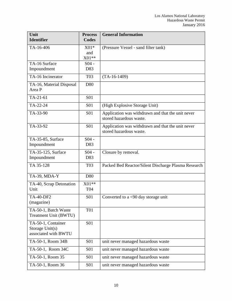
Los Alamos National Laboratory Hazardous Waste Permit
January 2016
10
Unit Identifier
Process Codes
General Information
TA-16-406 X01* and
X01**
(Pressure Vessel - sand filter tank)
TA-16 Surface Impoundment
S04 -D83
TA-16 Incinerator T03 (TA-16-1409)
TA-16, Material Disposal Area P
D80
TA-21-61 S01
TA-22-24 S01 (High Explosive Storage Unit)
TA-33-90 S01 Application was withdrawn and that the unit never stored hazardous waste.
TA-33-92 S01 Application was withdrawn and that the unit never stored hazardous waste.
TA-35-85, Surface Impoundment
S04 - D83
TA-35-125, Surface Impoundment
S04 - D83
Closure by removal.
TA 35-128
T03 Packed Bed Reactor/Silent Discharge Plasma Research
TA-39, MDA-Y D80
TA-40, Scrap Detonation Unit
X01** T04
TA-40-DF2 (magazine)
S01 Converted to a <90 day storage unit
TA-50-1, Batch Waste Treatment Unit (BWTU)
T01
TA-50-1, Container Storage Unit(s) associated with BWTU
S01
TA-50-1, Room 34B S01 unit never managed hazardous waste
TA-50-1, Room 34C S01 unit never managed hazardous waste
TA-50-1, Room 35 S01 unit never managed hazardous waste
TA-50-1, Room 36 S01 unit never managed hazardous waste

Los Alamos National Laboratory Hazardous Waste Permit
January 2016
11
Unit Identifier
Process Codes
General Information
TA-50-1, Room 38 S01 unit never managed hazardous waste
TA-50-1, Room 38A S01 unit never managed hazardous waste
TA-50-1, Room 59 S01 Radioactive Liquid Waste Treatment Facility (RLWTF)
TA-50-1, Room 60A
T04 Cementation Treatment Unit
Proposed treatment process was revised to generator treatment in a < 90 day storage area.
TA-50-37
T03 Controlled Air Incinerator (CAI)
TA-50-37 RAMROD
T04 Radioactive Materials Research, Operations and Demonstration Facility (RAMROD).
LANL withdraws permit request. Convert unit(s) to <90 day storage.
TA-50-37, Storage Tanks
S02 Located in Room 115
TA 50-37-112
S01, T03 Location of Controlled Air Incinerator (CAI), part of RAMROD Facility
TA-50-37-114 S01 Part of RAMROD
TA-50-37, Room 115 S01 - S02
Location of storage tanks and waste feed tanks
Part of RAMROD
TA-50-37, Room 117 S01 Room used for container storage.
Part of RAMROD
TA-50-37, Room 118
S01 Room used for container storage.
Part of RAMROD
TA-50-114 S01 Storage shed
TA-50-137
S01 Storage Bldg
Unit was never built
TA-50-138 S01 Storage Bldg
Unit was never built
TA-50-139 S01 Storage pad
Unit was never built

Los Alamos National Laboratory Hazardous Waste Permit
January 2016
12
Unit Identifier
Process Codes
General Information
TA-50-140 S01 Storage pad
Unit was never built
TA 53-166
S04 South Surface Impoundment
Change from closure as a TSD to cleanup under HSWA
TA 53-166 S04 NE Surface Impoundment
Change from closure as a TSD to cleanup under HSWA
TA 53-166 S04 NW Surface Impoundment
Change from closure as a TSD to cleanup under HSWA
TA-54-L, Waste Oil Storage Tank (WOST)
S02
TA-54-L, Truck Mounted Container Treatment System
T01 Unit was proposed in a 1993 permit modification and was withdrawn in a 1998 Part A.
TA-54-L, Bldg. 35, Storage/ Treatment Tanks (4)
S02 and (T01)
Pad below the tanks remains operational for waste storage.
TA-55-4, Oxygen Sparging Treatment Furnace
T04
TA-55-4, B38 S01 Unit also referred to as TA-55-4, basement, Area 2
TA-55-4, basement. Area 7 North end of basement CSA
S01 Unit was never used for hazardous waste storage and was withdrawn in the 1998 Part A.
TA-55-4-401 Mixed waste Monitoring CSA (Area 8 also called FLO-1)
S01 Unit was never used for hazardous waste storage and was withdrawn in the 1998 Part A.
TA-55-4-401 Sphere Material Removal CSA (Area 9)
S01 Unit was never used for hazardous waste storage and was withdrawn in the 1998 Part A.

Los Alamos National Laboratory Hazardous Waste Permit
January 2016
13
Unit Identifier
Process Codes
General Information
TA-55-4-401 CSA for Evaporator Salt Precipitate (Area 10)
S01 This unit was included as part of the evaporator glovebox storage tank system in the June 1996 TA-55 Part B
TA-55-4-433 Mixed Waste Monitoring CSA
S01 (Area 11 – referenced as Area 10 in June 1996)
Unit was never used for hazardous waste storage and was withdrawn in the 1998 Part A.
TA-55-4-432 CSA Glovebox Process Waste
S01 (Area 12 - referenced as Area 11 in June 1996)
Unit was never used for hazardous waste storage and was withdrawn in the 1998 Part A.
TA-55-41 CSA Vault S01 Unit was never used for hazardous waste storage and was withdrawn in the 1998 Part A.
TA-55-185 S01 Unit never managed hazardous waste.
TA-63 Chemical Waste Treatment Skid
T01 This unit was never constructed and was withdrawn in the 1998 Part A application.
TA-63 Liquid Waste Storage Tanks (6)
S02 These tanks were never constructed and were withdrawn in the 1998 Part A application.


