lord softshoetm isolator - lordfulfillment.com · 1 softshoe isolator use and maintenance manual...
TRANSCRIPT

LORD® SoftShoeTM Isolator Use and Maintenance Manual
USER MANUAL
OIL & GAS TECHNOLOGY | LORD CORPORATION

ii
SoftShoe Isolator Use and Maintenance Manual
Table of Contents1.0 Introduction ................................................................................1
2.0 Function .....................................................................................1
3.0 Assembly into MWD/LWD Tool String ......................................13.1 Mechanical .............................................................................13.2 O-Ring Placement ..................................................................13.3 UBHO Requirements .............................................................23.4 Muleshoe Landing Sleeve Requirements ..............................33.5 Location in MWD String ..........................................................4
4.0 Operating Parameters ...............................................................44.1 Maximum Operating Conditions .............................................44.2 Maximum Static Loads ...........................................................44.3 Explosive Decompression ......................................................4
5.0 Parts List ....................................................................................5
6.0 Redress Kits ..............................................................................6
7.0 Recommended Service Kit Stock ............................................7
8.0 Field Checks and Maintenance ................................................78.1 Overall Length (OAL) Inspection [Shoulder-to-Shoulder] ......7
9.0 Service Tools ..............................................................................89.1 Standard Tools ........................................................................89.2 Special Tools ..........................................................................9
10.0 Service Instructions ................................................................1010.1 Disassembly .........................................................................1010.2 Assembly ..............................................................................12
Listing of TablesTable 1: UBHO Drawings ........................................2Table 2: Muleshoe Landing Sleeve Drawings .........3Table 3: Maximum Operating Conditions ................4Table 4: Maximum Static Loads ..............................4Table 5: Medium SoftShoe Parts List .......................5Table 6: Large SoftShoe Parts List ..........................5Table 7: Medium SoftShoe Basic Redress Kits .......6Table 8: Large SoftShoe Basic Redress Kits ...........6Table 9: Suggested Stock .......................................7Table 10: OAL Shoulder-to-Shoulder .......................7Table 11: Installation Torque ....................................8Table 12: Thread Lubricants & Locker ....................8Table 13: Required Standard Tools .........................8Table 14: Special Tools ............................................9
Listing of FiguresFigure 1: O-Ring Placement .........................................1Figure 2: SoftShoe Assembly in UBHO ........................2Figure 3: UBHO Critical Geometry ...............................2Figure 4: Y-65057-3-1/ Y-65248-3-1 Altered Muleshoe, 1-Piece Bottom Sleeve ..............3Figure 5: Y-65057-2-1/ Y-65248-2-1 Altered Muleshoe, 1-Piece Bottom Sleeve ..............3Figure 6: Y-65057-2-1/ Y-65248-2-1 Altered Muleshoe, Bottom Sleeve with Insert ..........3Figure 7: SoftShoe Isolator Location in UBHO .............4Figure 8: J-28542-31/ -35 SoftShoe Shoulder-to- Shoulder Length ..........................................7Figure 9: Internal Joints ...............................................8Figure 10: External Joints ............................................8Figure 11: Torque Wrench, Assembly Tool, Pin Wrench (Preferred Tools) ..........................................8Figure 12: Friction Vise (ZV55-54) (Preferred Tool) ......9Figure 13: Chain Vise (Optional Tool) ...........................9Figure 14: Gearench C27-34-F Chain Wrench (Optional Tool) .............................................9Figure 15: FAS-64603-2 / -3 Assembly Tool ..................9

1
SoftShoe Isolator Use and Maintenance Manual
1.0 IntroductionLORD® J-28542-31 and J-28542-35 MWD Tool SoftShoeTM
Isolators (patent pending) are designed for service in air, foam, or
mud drilling operations. The use and maintenance requirements
are summarized in this document. The Medium and Large
SoftShoe Isolator components differ slightly to ensure that the
most appropriate design is used to yield the highest reliability and
longevity.
2.0 FunctionThe LORD J-28542-31 / J-28542-35 MWD Tool SoftShoe Isolator
(herein referred to as the SoftShoe Isolator) is designed to protect
the sensitive electronics in an MWD string by isolating these
components from mid-range and high frequency vibrations. The
isolator will also attenuate certain levels of shock inputs.
3.0 Assembly into MWD/LWD Tool String
3.1 MechanicalThe Isolator has been designed to be assembled into the UBHO
using standard 3/4-10 UNC grub screws and standard o-rings.
3.2 O-Ring PlacementRefer to Figure 1.
Figure 1: O-Ring Placement(4) O-rings No O-rings

2
3.3 UBHO RequirementsThe SoftShoe Isolator requires the use of a UBHO that has a
sufficient bore depth to accommodate the additional 8.25" of
length added to the Muleshoe Landing Sleeve, such that it will
not protrude into the connection. This ensures that the MWD and
Muleshoe Landing Sleeve itself are not subject to high wash.
The standard UBHO o-ring gland area without the SoftShoe is
approximately 4 inches long. When adding the SoftShoe Isolator in
the UBHO, the gland area is increased to 7 inches in length. The
o-rings are now installed on the SoftShoe instead of the Muleshoe
Landing Sleeve. This allows the Muleshoe Landing Sleeve to
move freely. The gland geometry is critical in order to sufficiently
seal. UBHO drawings are available through LORD.
Figure 2: SoftShoe Assembly in UBHO
Figure 3: UBHO Critical GeometryCritical Geometry
Gap to allow Movement
Table 1: UBHO Drawings
Medium Drawing Number
Large Drawing Number
Short Description
Y-65248-1 Y-65057-1 UBHO
3
3.4 Muleshoe Landing Sleeve RequirementsThe Isolator requires the use of a standard muleshoe landing
sleeve that has been altered. The modification involves adding
threads to the downstream end of the Muleshoe Landing Sleeve
to attach to the SoftShoe Isolator. Alternatively, Muleshoe Sleeves
can be made new in this configuration, in which case, the external
o-ring grooves may be eliminated. Drawings detailing this
modification are available from LORD.
Table 2: Muleshoe Landing Sleeve Drawings
Medium Drawing Number
Large Drawing Number
Short Description
Y-65248-2-1 Y-65057-2-1 Altered Muleshoe Landing Sleeve
Y-65248-3-1* Y-65057-3-1* Altered Muleshoe Landing Sleeve
*The 3-1 configurations are recommended for optimum performance.
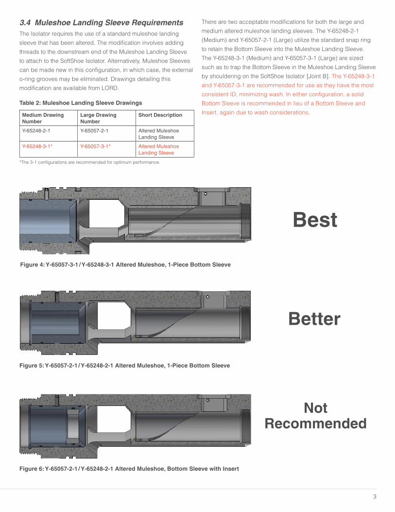
There are two acceptable modifications for both the large and
medium altered muleshoe landing sleeves. The Y-65248-2-1
(Medium) and Y-65057-2-1 (Large) utilize the standard snap ring
to retain the Bottom Sleeve into the Muleshoe Landing Sleeve.
The Y-65248-3-1 (Medium) and Y-65057-3-1 (Large) are sized
such as to trap the Bottom Sleeve in the Muleshoe Landing Sleeve
by shouldering on the SoftShoe Isolator [Joint B]. The Y-65248-3-1
and Y-65057-3-1 are recommended for use as they have the most
consistent ID, minimizing wash. In either configuration, a solid
Bottom Sleeve is recommended in lieu of a Bottom Sleeve and
Insert, again due to wash considerations.
Best
Figure 4: Y-65057-3-1 / Y-65248-3-1 Altered Muleshoe, 1-Piece Bottom Sleeve
Better
Figure 5: Y-65057-2-1 / Y-65248-2-1 Altered Muleshoe, 1-Piece Bottom Sleeve
NotRecommended
Figure 6: Y-65057-2-1 / Y-65248-2-1 Altered Muleshoe, Bottom Sleeve with Insert

4
Figure 7: SoftShoe Isolator Location in UBHO
3.5 Location in MWD StringThe Isolator has been designed to support the MWD string and
attach directly to the downstream end of the Muleshoe Landing
Sleeve located in the UBHO sub. This can be seen in detail in the
illustrated view drawings available from LORD.
4.0 Operating Parameters
4.1 Maximum Operating ConditionsThe Isolator was designed for the operating conditions shown in
Table 3.
Table 3: Maximum Operating Conditions
Temperature 350°F maximum
Pressure N/A
The Isolator can withstand temperatures of 350°F and beyond;
however, extended periods of exposure to this extreme condition
should be avoided. Prolonged exposure to consistent elevated
temperatures (>280°F) will accelerate the degradation of the
elastomer package, reducing the elastomer’s overall useful life.
Elastomer Kits rated for high temperature use are available,
please contact your LORD representative for details.
The Isolator has no pressure rating limitations as it is pressure
compensated with the downhole environment.
4.2 Maximum Static LoadsThe maximum loads for the Isolator are shown in Table 4. Note
that the recommended assembly torque is 350 ft-lbs, well below
the maximum torque.
Table 4: Maximum Static Loads
Maximum Torque 500 ft-lb
Axial Load (Fishing Load) 20,000 lb
4.3 Explosive DecompressionThe Isolator was not designed to function following an explosive
decompression event. If any such event should occur, the Isolator
should be removed from use, completely broken down, assessed
for damage, and any damaged components replaced.
Downhole
UBHO
SoftShoe Isolator
Altered Muleshoe Landing Sleeve
5
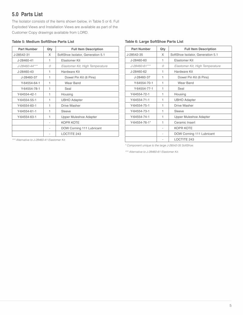
5.0 Parts ListThe Isolator consists of the items shown below, in Table 5 or 6. Full
Exploded Views and Installation Views are available as part of the
Customer Copy drawings available from LORD.
Table 5: Medium SoftShoe Parts List
Part Number Qty Full Item Description
J-28542-31 X SoftShoe Isolator, Generation 5.1
J-28460-41 1 Elastomer Kit
J-28460-44*** 0 Elastomer Kit, High Temperature
J-28460-43 1 Hardware Kit
J-28460-37 1 Dowel Pin Kit (6 Pins)
Y-64554-64-1 1 Wear Band
Y-64554-78-1 1 Seal
Y-64554-42-1 1 Housing
Y-64554-55-1 1 UBHO Adapter
Y-64554-60-1 1 Drive Washer
Y-64554-61-1 1 Sleeve
Y-64554-63-1 1 Upper Muleshoe Adapter
- KOPR KOTE
- DOW Corning 111 Lubricant
- LOCTITE 243
*** Alternative to J-28460-41 Elastomer Kit.
Table 6: Large SoftShoe Parts List
Part Number Qty Full Item Description
J-28542-35 X SoftShoe Isolator, Generation 5.1
J-28460-60 1 Elastomer Kit
J-28460-61*** 0 Elastomer Kit, High Temperature
J-28460-62 1 Hardware Kit
J-28460-37 1 Dowel Pin Kit (6 Pins)
Y-64554-70-1 1 Wear Band
Y-64554-77-1 1 Seal
Y-64554-72-1 1 Housing
Y-64554-71-1 1 UBHO Adapter
Y-64554-75-1 1 Drive Washer
Y-64554-73-1 1 Sleeve
Y-64554-74-1 1 Upper Muleshoe Adapter
Y-64554-76-1* 1 Ceramic Insert
- KOPR KOTE
- DOW Corning 111 Lubricant
- LOCTITE 243
* Component unique to the large J-28542-35 SoftShoe.
*** Alternative to J-28460-61 Elastomer Kit.

6
6.0 Redress KitsCertain components on the Isolator are intended to be replaced
on a regular basis. These items can be purchased as part of a
basic redress kit, see Table 7 or 8. Additionally, major metals are
available for purchase - refer to the Y-64554-XX Part Numbers
listed in Table 5 or 6.
Table 7: Medium SoftShoe Basic Redress Kits
Kit Number Kit Description Qty Component Part Number
Description
J-28460-41 Elastomer Kit1 J-28542-24 Elastomer Stack, Compression
1 J-28542-25 Elastomer Stack, Rebound
J-28460-44 HT Elastomer Kit1 J-28542-33 HT Elastomer Stack, Compression
1 J-28542-34 HT Elastomer Stack, Rebound
J-28460-43 Hardware Kit
1 Y-64554-64 Wear Band
1 J-28460-37 Dowel Pin Kit
1 Y-64554-78 Seal
J-28460-37 Pin Kit 6 LSTP9-18-10 Dowel Pins
Table 8: Large SoftShoe Basic Redress Kits
Kit Number Kit Description Qty Component Part Number
Description
J-28460-60 Elastomer Kit1 J-28542-36 Elastomer Stack, Compression
1 J-28542-237 Elastomer Stack, Rebound
J-28460-61 HT Elastomer Kit1 J-28542-38 HT Elastomer Stack, Compression
1 J-28542-39 HT Elastomer Stack, Rebound
J-28460-62 Hardware Kit
1 Y-64554-70 Wear Band
1 J-28460-37 Dowel Pin Kit
1 Y-64554-77 Seal
J-28460-37 Pin Kit 6 LSTP9-18-10 Dowel Pins

7
7.0 Recommended Service Kit StockLORD recommends that certain service kit items be put in stock
by the users of the Isolator to facilitate quick repair or replacement
of wear items. This section will detail the recommended kits and
quantities that should be kept on hand.
Quantities of each kit are given per number of Isolators in service
(see Table 9). For example, for each SoftShoe Isolator in service,
two (2) Hardware Kits are recommended to be kept in stock. For
some lower wear items, a single kit can support several Isolators.
Table 9: Suggested Stock
Medium SoftShoe Part Number
Large SoftShoe Part Number
Short DescriptionSuggested Stock
Quantity per Isolator(s)
J-28460-41 J-28460-60** Elastomer Kit 1 2
J-28460-43 J-28460-62* Hardware Kit 2 1
Y-64554-42-1 Y-64554-72-1 Housing 1 5
Y-64554-55-1 Y-64554-71-1 UBHO Adapter 1 5
Y-64554-63-1 Y-64554-74-1 Muleshoe Adapter 1 5
Y-64554-61-1 Y-64554-73-1 Sleeve 2 1
Y-64554-60-1 Y-64554-75-1 Drive Washer 1 5
N/A Y-64554-76-1 Ceramic Insert 1 5
* Customer’s discretion to be used, alternatively individual components could be stocked in lieu of hardware kit.
**Alternative versions could be stocked in place.
8.0 Field Checks and Maintenance
8.1 Overall Length (OAL) Inspection [Shoulder-to-Shoulder]The nominal starting gap between the Housing and Muleshoe
Adapter on the Isolator is 0.395-0.375 inches long when measured
shoulder-to-shoulder as shown in Figure 8. Between runs, the
length can be checked as a reference using the below method.
The tool should be fully inspected and evaluated in between runs
or after 400 hours, whichever comes first.
Table 10: OAL Shoulder-to-Shoulder
Nominal 0.395 - 0.375 inches
Minimum 0.280 inches
The anti-rotation feature should also be checked before the
Isolator is run below the rotary table. To do so, attempt to manually
rotate the Isolator. If the part rotates, tear down the Isolator and
ensure pins are installed and are in working condition.
Figure 8: J-28542-31 / -35 SoftShoe Shoulder-to-Shoulder
Length

8
Table 11: Installation Torque
Joint Installation Torque
A 350 ft-lb
B 350 ft-lb
C 150 ft-lb
Table 12: Thread Lubricants & Locker/Sealant
Joint Lubricant/Thread Locker/Thread Sealant
A KOPR KOTE
B KOPR KOTE* or LOCTITE 243
C LOCTITE 243
*KOPR KOTE recommended.
9.0 SERVICE TOOLS
9.1 Standard ToolsThe Isolator was designed to be assembled and disassembled
using primarily standard tools.
Pipe wrenches shall NOT be used during assembly or
disassembly of the Isolator. Additionally, torches or similar heat
generating devices shall NOT be used in an attempt to loosen
joints.
Table 13: Required Standard Tools
SoftShoe Size
Size Tool Description Part Number
Large 3.75 inch Friction Vise Petol Gearench: ZV55-54
Large 3.75 inch Friction Vise Inserts Petol Gearench: ZUV55:3.750 – modified, trimmed to OAL of 4.5"
Medium 3.125 inch Friction Vise Inserts Petol Gearench: ZUV55:3.125 - modified, trimmed to OAL of 4.5"
Both — Chain Vise
Both 3/8 dia Pin Pin Wrench LORD: J-28542-5
Both — Chain Wrench Petol Gearench: C27-34-F
Large 3.75 inch Friction Tong Petol Gearench: ZT5:3.750
Medium 3.125 inch Friction Tong Petol Gearench: ZT5:3.125
Both 1/2 Drive Breaker Bar or Ratchet
Both 1/2 Drive Torque Wrench
Preferred Tool Alternate Tool
Figure 9: Internal Joints Figure 10: External Joints
Joint C
Joint A
Joint B
Figure 11: Torque Wrench, Assembly Tool, Pin Wrench (Preferred Tools)

9
9.2 Special ToolsSpecialized tools are used to assist in the assembly of the Isolator
and are available directly from LORD. These tools are shown in
Table 14.
Table 14: Special Tools
SoftShoe Tool No. Tool Description
J-28542-31 (Medium) FAS-64603-2 Drive Nut Socket, Medium
J-28542-35 (Large) FAS-64603-3 Drive Nut Socket, Large
FAS-64603-2 / -3 is a socket used to install the drive washer.
(FAS-64603-2, Medium is pictured)
Figure 12: Friction Vise (ZV55-54) (Preferred Tool) Figure 13: Chain Vise (Optional Tool)
Figure 14: Gearench C27-34-F Chain Wrench (Optional Tool)
Figure 15: FAS-64603-2 / -3 Assembly Tool
10
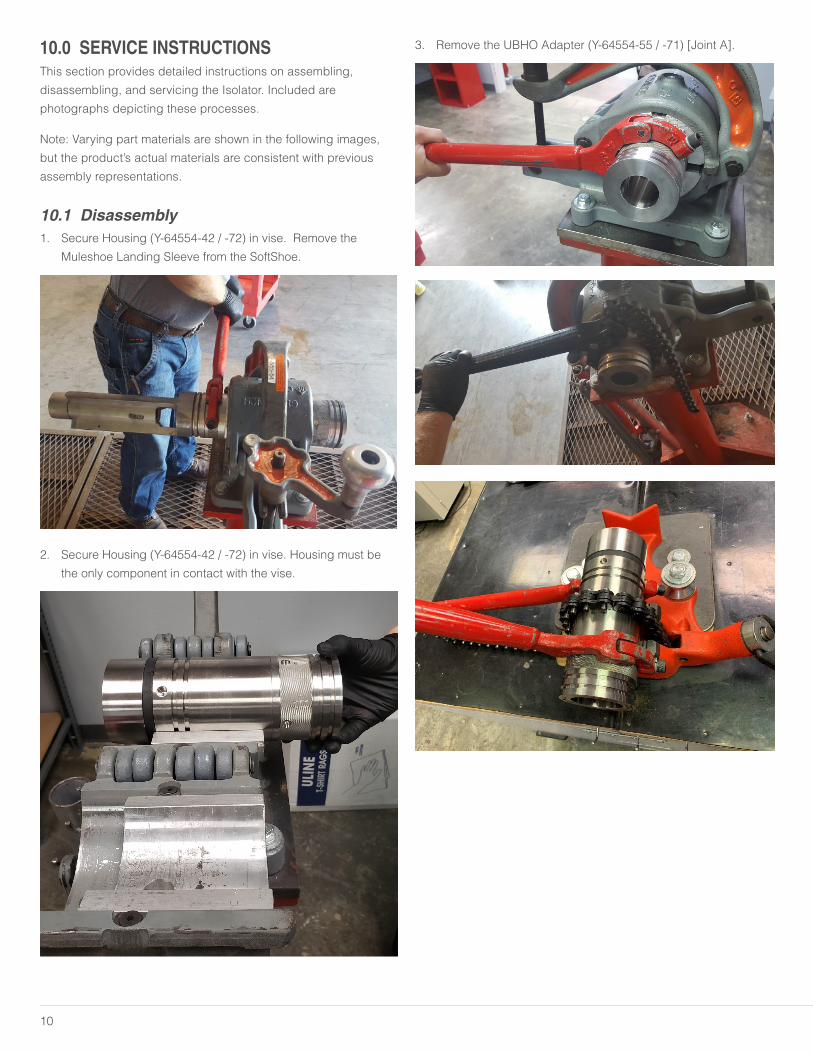
10.0 SERVICE INSTRUCTIONSThis section provides detailed instructions on assembling,
disassembling, and servicing the Isolator. Included are
photographs depicting these processes.
Note: Varying part materials are shown in the following images,
but the product’s actual materials are consistent with previous
assembly representations.
10.1 Disassembly1. Secure Housing (Y-64554-42 / -72) in vise. Remove the
Muleshoe Landing Sleeve from the SoftShoe.
2. Secure Housing (Y-64554-42 / -72) in vise. Housing must be
the only component in contact with the vise.
3. Remove the UBHO Adapter (Y-64554-55 / -71) [Joint A].

11
4. Remove the Compression Elastomer Stack (J-28542-24 / -33,
J-28542-36 / -38).
5. Remove the Drive Washer (Y-64554-60 / -75) and Sleeve
(Y-64554-61 / -73) using the Assembly Tool (FAS-64603-2 / -3)
[Joint B].
6. Remove the Rebound Elastomer Stack (J-28542-25 / -34,
J-28542-37 / -39).

12
7. Slide apart the Muleshoe Adapter (Y-64554-63 / -74) from the
Housing.
8. Remove the (6) Dowel Pins (J-28460-37) and Seal (Y-64554-77
/ -78).
9. Remove Wear Band (Y-64554-64 / -70) from UBHO Adapter
(Y-64554-55 / -71).
10.2 Assembly1. Install Wear Band (Y-64554-64 / -70) into UBHO Adapter
(Y-64554-55 / -71).

13
2. **Large SoftShoe (J-28542-35) Only**
Install the Wash Insert (Y-64554-76) into the Muleshoe Adapter
(Y-64554-74) using Blue Loctite 243.
3. Install the Seal (Y-64554-77 / -78) onto the Muleshoe Adapter
(Y-64554-63 / -74).
4. Grease Dowel Pin Grooves, Install (6) Pins (J-28460-37) into
Muleshoe Adapter (Y-64554-63 / -74).
5. Slide the Housing (Y-64554-42 / -72) onto the Muleshoe
Adapter (Y-64554-63 / -74).
6. Install the Rebound Elastomer Stack (J-28542-25 / -34,
J-28542-37 / -39).
7. Install the Sleeve (Y-64554-61 / -73) into the Drive Washer
(Y-64554-60 / -75).

14
8. Apply Loctite 243 to the Drive washer (Y-64554-60 / -75) and
install.
9. Torque Drive Washer (Y-64554-60 / -75) to 150 ft-lbs with
Assembly Tool (FAS-64603-2 / -3).
15
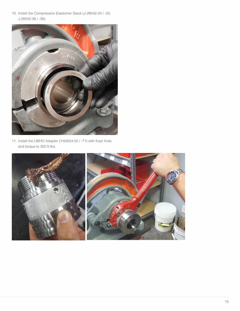
10. Install the Compression Elastomer Stack (J-28542-24 / -33,
J-28542-36 / -38).
11. Install the UBHO Adapter (Y-64554-55 / -71) with Kopr Kote
and torque to 350 ft-lbs.

LORD provides valuable expertise in adhesives and coatings, vibration and motion control, and magnetically responsive technologies. Our people work in collaboration with our customers to help them increase the value of their products. Innovative and responsive in an ever-changing marketplace, we are focused on providing solutions for our customers worldwide.
LORD Corporation World Headquarters111 Lord DriveCary, NC 27511-7923 USA
Customer Support Center (in United States & Canada)+1 877 ASK LORD (275 5673)
www.lord.com
For a listing of our worldwide locations, visit LORD.com.
Houston Area Office 2455 FM 2920Suite BSpring, TX 77388
Phone: +1 855 796 1595
©2019 LORD Corporation OD UM1003 | MRO-00004 (Rev.0 4/19)
No part of this publication may be reproduced, transmitted, transcribed, stored in a retrieval system or translated into any language in any form by any means without written permission of LORD Corporation.
LORD and SoftShoe are trademarks of LORD Corporation or one of its subsidiaries.