lord, m. l., turner-smith, a . “ orthopedic prosthetics ... · lord, m. l., turner-smith, a . “...
TRANSCRIPT

Lord, M. L., Turner-Smith, A . “ Orthopedic Prosthetics and Orthotics in Rehabilitation.”The Biomedical Engineering Handbook: Second Edition.Ed. Joseph D. BronzinoBoca Raton: CRC Press LLC, 2000

140Orthopedic Prosthetics
and Orthotics inRehabilitation
140.1 Fundamentals140.2 Applications
Computer-Aided Engineering in Customized Component Design • Examples of Innovative Component Design
140.3 Summary
An orthopedic prosthesis is an internal or external device that replaces lost parts or functions of theneuroskeletomotor system. In contrast, a orthopedic orthosis is a device that augments a function of theskeletomotor system by controlling motion or altering the shape of body tissue. For example, an artificialleg or hand is a prosthesis, whereas a calliper (or brace) is an orthosis. This chapter addresses onlyorthoses and external orthopedic prostheses; internal orthopedic prostheses, such as artificial joints, area subject on their own.
When a human limb is lost through disease or trauma, the integrity of the body is compromised inso many ways that an engineer may well feel daunted by the design requirements for a prostheticreplacement. Consider the losses from a lower limb amputation. Gone is the structural support for theupper body in standing, along with the complex joint articulations and muscular motor system involvedin walking. Lost also is the multimode sensory feedback, from inter alia pressure sensors on the sole ofthe foot, length and force sensors in the muscles, and position sensors in the joints, which closed thecontrol loop around the skeletomotor system. The body also has lost a significant percentage of its weightand is now asymmetrical and unbalanced.
We must first ask if it is desirable to attempt to replace all these losses with like-for-like components.If so, we need to strive to make a bionic limb of similar weight embodying anthropomorphic articulationswith equally powerful motors and distributed sensors connected back into the wearer’s residual neuro-muscular system. Or, is it better to accept the losses and redefine the optimal functioning of the newunit of person-plus-technology? In many cases, it may be concluded that a wheelchair is the optimalsolution for lower limb loss. Even if engineering could provide the bionic solution, which it certainlycannot at present despite huge inroads made into aspects of these demands, there remain additionalproblems inherent to prosthetic replacements to consider. Of these, the unnatural mechanical interfacebetween the external environment and the human body is one of the most difficult. Notable, in place ofweight bearing through the structures of the foot that are well adapted for this purpose, load must nowbe transferred to the skeletal structures via intimate contact between the surface of residual limb andprosthesis; the exact distribution of load becomes critical. To circumvent these problems, an alternativedirect transcutaneous fixation to the bone has been attempted in limited experimental trials, but this
Marilyn LordKing’s College London
Alan Turner-SmithKing’s College London
© 1997 by CRC Press LLC
brings its own problems of materials biocompatability and prevention of infection ingress around theopening through the skin. Orthotic devices are classified by acronyms that describe the joint which theycross. Thus an AFO is an ankle-foot orthosis, a CO is a cervical orthosis (neck brace or collar), and aTLSO is a thoracolumbosacral orthosis (spinal brace or jacket). The main categories are braces for thecervix (neck), upper limb, trunk, lower limb, and foot. Orthoses are generally simpler devices thanprostheses, but because orthoses are constrained by the existing body shape and function, they can presentan equally demanding design challenge. Certainly the interaction with body function is more critical,and successful application demands an in-depth appreciation of both residual function and the probablereaction to external interference. External orthotics are often classified as structural or functional, theformer implying a static nature to hold an unstable joint and the latter a flexible or articulated systemto promote the correct alignment of the joints during dynamic functioning. An alternative orthoticapproach utilizes functional electrical stimulation (FES) of the patient’s own muscles to generate appro-priate forces for joint motion; this is dealt with in Chapter 142.
140.1 Fundamentals
Designers of orthotic and prosthetic devices are aware of the three cardinal considerations—function,structure, and cosmesis.
For requirements of function, we must be very clear about the objectives of treatment. This requiresfirst an understanding of the clinical condition. Functional prescription is now a preferred route for themedical practitioner to specify the requirements, leaving the implementation of this instruction to theprosthetist, orthotist, or rehabilitation technologist. The benefits of this distinction between client spec-ification and final hardware will be obvious to design engineers. Indeed, the influence of design procedureson the supply process is a contribution from engineering that is being appreciated more and more.
The second requirement for function is the knowledge of the biomechanics that underlies both thedysfunction in the patient and the function of proposed device to be coupled to the patient. Kinematics,dynamics, energy considerations, and control all enter into this understanding of function. Structure isthe means of carrying the function, and finally both need to be embodied into a design that is cosmeticallyacceptable. Some of the fundamental issues in these concepts are discussed here.
To function well, the device needs an effective coupling to the human body. To this end, there is oftensome part that is molded to the contours of the wearer. Achieving a satisfactory mechanical interface ofa molded component depends primarily on the shape. The internal dimensions of such components arenot made an exact match to the external dimensions of the limb segment, but by a process of rectification,the shape is adjusted to relieve areas of skin with low load tolerance. The Shapes are also evolved toachieve appropriate load distribution for stability of coupling between prosthetic socket and limb or, inorthotic design, a system of usually three forces that generates a moment to stabilize a collapsing joint(Fig. 140.1). Alignment is a second factor influencing the interface loading. For lower limb prosthesesparticularly, the alignment of the molded socket to the remainder of the structural components also willbe critical in determining the moments and forces transmitted to the interface when the foot is flat onthe ground. The same is true for lower limb orthoses, where the net action of the ground reaction forcesand consequent moments around the natural joints are highly dependent on the alignment taken up bythe combination of orthosis and shoe. Adjustability may be important, particularly for children orprogressive medical conditions. Functional components that enable desirable motions are largely straight-forward engineering mechanisms such as hinges or dampers, although the specific design requirementsfor their dynamic performance may be quite complex because of the biomechanics of the body. Anexample of the design of knee joints is expanded below. These motions may be driven from externalpower sources but more often are passive or body-powered mechanisms. In orthoses where relativelysmall angular motions are needed, these may be provided by material flexibility rather than mechanisms.
The structural requirements for lower-limb prosthetics have been laid down at a consensus meeting(1978) bases on biomechanical measurement of forces in a gait laboratory, referred to as the Philadelphiastandards and soon to be incorporated into an ISO standard (ISO 13404,5; ISO 10328).Not only are the
© 1997 by CRC Press LLC

load level and life critical, but so is the mode of failure. Sudden failure of an ankle bolt resulting indisengagement of an artificial foot is not only potentially life-threatening to an elderly amputee who fallsand breaks a hip but also can be quite traumatic to unsuspecting witnesses of the apparent event ofautoamputation. Design and choice of materials should ensure a controlled slow yielding, not brittlefracture. A further consideration is the ability of the complete structure to absorb shock loading, eitherthe repeated small shocks of walking at the heel strike or rather more major shocks during sports activitiesor falls. This minimizes the shock transmitted through the skin to the skeleton, known to cause bothskin lesions and joint degeneration. Finally, the consideration of hygiene must not be overlooked; theuser must be able to clean the orthosis or prosthesis adequately without compromising its structure orfunction.
Added to the two elements of structure and function, the third element of cosmesis completes thetrilogy. Appearance can be of great psychological importance to the user, and technology has its contri-bution here, too. As examples, special effects familiar in science fiction films also can be harnessed toprovide realistic cosmetic covers for hand or foot prostheses. Borrowing from advanced manufacturingtechnology, optical shape scanning linked to three-dimensional (3D) computer-aided design, and CNCmachining can be pressed into service to generate customized shapes to match a contralateral remaininglimb. Up-to-date materials and component design each contribute to minimize the “orthopedic appli-ance” image of the devices (Fig. 140.2). In providing cosmesis, the views of the user must remainparamount. The wearer will often choose an attractive functional design in preference to a life like designthat is not felt to be part of his or her body.
Upper limb prostheses are often seen as a more interesting engineering challenge than lower limb,offering the possibilities for active motor/control systems and complex articulations. However, the marketis an order of magnitude smaller and cost/benefit less easy to prove—after all, it is possible to function
FIGURE 140.1 Three-force system required in an orthosis to control a valgus hindfoot due to weakness in thehindfoot supinators.
© 1997 by CRC Press LLC

fairly well with one arm, but try walking with one leg. At the simplest end, an arm for a below-elbowamputee might comprise a socket with a terminal device offering a pincer grip (hand or hook) that canbe operated through a Bowden cable by shrugging the shoulders. Such body-powered prostheses mayappear crude, but they are often favored by the wearer because of a sense of position and force feedbackfrom the cable, and they do not need a power supply. Another, more elegant method of harnessing bodypower is to take a muscle made redundant by an amputation and tether its tendon through an artificiallyfashioned loop of skin: the cable can then be hooked through the loop [Childress, 1989].
Externally powered devices have been attempted using various power sources with degrees of success.Pneumatic power in the form of a gas cylinder is cheap and light, but recharging is a problem thatexercised the ingenuity of early suppliers: where supplies were not readily available, even schemes toinvolve the local fire services with recharging were costed. Also, contemplate the prospect of bringing aloaded table fork toward your face carried on the end of a position-controlled arm powered with spongy,low-pressure pneumatic actuators, and you will appreciate another aspect of difficulties with this source.Nevertheless, gas-powered grip on a hand can be a good solution. Early skirmishes with stiffer hydraulicservos were largely unsuccessful because of power supply and actuator weight and oil leakage. Electricactuation, heavy and slow at first, has gradually improved to establish its premier position. Input controlto these powered devices can be from surface electromyography or by mechanical movement of, forexample, the shoulder or an ectromelic limb. Feedback can be presented as skin pressure, movement ofa sensor over the skin, or electric stimulation. Control strategies range from position control around a
FIGURE 140.2 The ARGO reciprocating-gait orthosis, normally worn under the clothing, with structural compo-nents produced from 3D CAD. (Courtesy of Hugh Steeper, Ltd., U.K.)
© 1997 by CRC Press LLC

single joint or group of related joints through combined position and force control for hand grip tocomputer-assisted coordination of entire activities such as feeding.
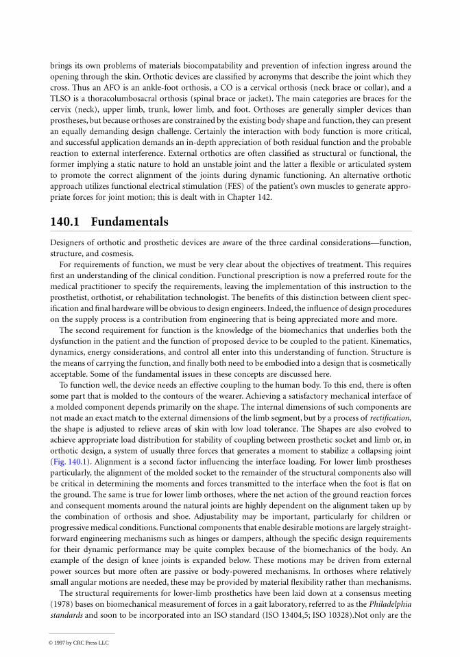
The physical designs in prosthetic and orthotic devices has changed substantially over the past decade.One could propose that this is solely the introduction of new materials. The sockets of artificial limbshave always been fashioned to suit the individual patient, historically by carving wood, shaping leather,or beating sheet metal. Following the introduction of thermosetting fiber-reinforced plastics hand-shapedover a plaster cast of the limb residuum, substitution of thermoforming plastics that could be automat-ically vacuum-formed made a leap forward to give light, rapidly made, and cosmetically improvedsolutions. Polypropylene is the favored material in this application. The same materials permitted thenew concept of custom-molded orthoses. Carbon fiber composites substituted for metal have certainlyimproved the performance of structural components such as limb shanks. But some of the progress owesmuch to innovative thinking. The flex foot is a fine example, where a traditional anthropomorphic designwith imitation ankle joint and metatarsal break is completely abandoned and a functional design adoptedto optimize energy storage and return. This is based on two leaf springs made from Kevlar, joined togetherat the ankle with one splaying down toward the toes to form the forefoot spring and the other rearwardto form the heel spring (Fig. 140.3). Apart from the gains for the disabled athletes for whom the footwas designed–and these are so remarkable that there is little point in competing now without thisfoot–clients across all age groups have benefited from the adaptability to rough ground and shock-absorption capability.
FIGURE 140.2 (continued)
© 1997 by CRC Press LLC
140.2 Applications
Computer-Aided Engineering in Customized Component Design
Computer-aided engineering has found a fertile ground for exploitation in the process of design ofcustomized components to match to body shape. A good example is in sockets for artificial limbs. Whatprosthetists particularly seek is the ability to produce a well-fitting socket during the course of a singlepatient consultation. Traditional craft methods of casting the residual limb in plaster of paris, pouringa positive mold, manual rectification, and then socket fabrication over the rectified cast takes too long.
By using advanced technology, residual limb shapes can be captured in a computer, rectified bycomputer algorithms, and CNC machined to produce the rectified cast in under an hour so that withthe addition of vacuum-formed machinery to pull a socket rapidly over the cast, the socket can be readyfor trial fitting in one session. There are added advantages too, in that the shape is now stored in digitalform in the computer and can be reproduced or adjusted whenever and wherever desired. Although suchsystems are still in an early stage of introduction, many practicing prosthetists in the United States havenow had hands-on experience of this technology, and a major evaluation by the Veterans Administrationhas been undertaken [Houston et al., 1992].
Initially, much of the engineering development work went into the hardware components, a difficultbrief in view of the low cost target for a custom product. Requirements are considerably different fromthose of standard engineering, e.g., relaxation in the accuracies required (millimeters, not microns);aneed to measure limb or trunk parts that are encumbered by the attached body, which may resist beingorientated conveniently in a machine and which will certainly distort with the lightest pressure; and aneed to reproduce fairly bulky items with strength to be used as a sacrificial mold. Instrumentation forbody shape scanning has been developed using methods of silhouettes, Moiré fringes, contact probesmeasuring contours of plaster casts, and light triangulation. Almost universally the molds are turned by“milling on a spit” [Duncan & Mair, 1983], using an adapted lathe with a milling head to spiral downa large cylindrical plug of material such as plaster of paris mix. Rehabilitation engineers watch with greatinterest, some with envy, the developments in rapid prototyping manufacture, which is so successful inreducing the cycle time for one-off developments else-where in industry, but alas the costs of techniques suchas stereolithography are as yet beyond economic feasi-bility for our area.
Much emphasis also has been placed on the graphicsand algorithms needed to achieve rectification. Opin-ions vary as to what extent the computer should simplyprovide a more elegant tool for the prosthetist to exer-cise his or her traditional skills using 3D modeling andon-screen sculpting as a direct replacement for manualplaster rectification or to what extent the computersystem should take over the bulk of the process by anexpert systems approach. Systems currently availabletend to do a little of each. A series of rectification mapscan be held as templates, each storing the appropriaterelief or buildup to be applied over a particular ana-tomic area of the limb. Thus the map might provide fora ridge to be added down the front of the shin of a lowerlimb model so that the eventual socket will not pressagainst the vulnerable bony prominence of the tibia(Fig. 140.4). Positioning of the discrete regions to matchindividual anatomy might typically be anchored to oneor more anatomic features indicated by the prosthetist. FIGURE 140.3 The Flex Foot.
© 1997 by CRC Press LLC

The prosthetist is also able to free-form sculpt a particular region by pulling the surface interactivelywith reference to graphic representation (Fig. 140.5); this is particularly useful where the patient hassome unusual feature not provided for in the templates.
As part of this general development, finite-element analysis has been employed to model the soft tissuedistortion occurring during limb loading and to look at the influence of severity of rectification in theresultant distribution of interface stress [e.g., Reynolds & Lord, 1992] (Fig. 140.6). In engineering terms,this modeling is somewhat unusual and decidedly nonlinear. For a start, the tissues are highly deformablebut nearly incompressible, which raises problems of a suitable Poisson ratio to apply in the modeling.Values of n = 0.3 to n = 0.49 have been proposed, based on experimental matching of stress-strain curvesfrom indentation of limb tissue in vivo. In reality, though, compression (defined as a loss of volume)may be noted in a limb segment under localized external pressure due to loss of mass as first the blood
FIGURE 140.4 A rectification require defined over the tibia of lower limb stump using the Shapemaker applicationfor computer-aided socket design.
FIGURE 140.5 Adjusting a socket contour with reference to 3D graphics and cross-sectional profiles in the UCLCASD system. (Reproduced from Reynolds and Lord [1992] with permission.)
© 1997 by CRC Press LLC

is rapidly evacuated and then interstitial fluids are more slowly squeezed out. Also, it is difficult to definethe boundaries of the limb segment at the proximal end, still attached to the body, where soft tissues caneasily bulge up and out. This makes accurate experimental determination of the stress-strain curves forthe tissue matrix difficult. A nonlinear model with interface elements allowing slip to occur between skinand socket at the limit of static friction may need to be considered, since the frictional conditions at theinterface will determine the balance between shear and direct stresses in supporting body weight againstthe sloping sidewalls. Although excessive shear at the skin surface is considered particularly damaging,higher pressures would be required in its complete absence.
In a similar vein, computer-aided design (CAD) techniques are also finding application in the designof bespoke orthopedic footwear, using CAD techniques from the volume fashion trade modified to suitthe one-off nature of bespoke work. This again requires the generation of a customized mold, or shoelast, for each foot, in addition to the design of patterns for the shoe uppers [Lord et al., 1991]. Thephilosophy of design of shoe lasts is quite different from that of sockets, because last shapes haveconsiderable and fundamental differences from foot shapes. In this instance, a library of reference lastshapes is held, and a suitable one is selected both to match the client’s foot shape and to fulfill theshoemaking needs for the particular style and type of shoe. The schematic of the process followed indevelopment of the Shoemaster system is shown in Fig. 140.7.
Design of shoe inserts is another related application, with systems to capture, manipulate, and repro-duce underfoot contours now in commercial use. An example is the Ampfit system, where the foot isplaced on a platform to which preshaped arch supports or other wedges or domes may first be attached.A matrix of round-ended cylinders is then forced up by gas pressure through both platform and supports,supporting the foot over most of the area with an even load distribution. The shape is captured fromthe cylinder locations and fed into a computer, where rectification can be made similar to that describedfor prosthetic sockets. A benchtop CNC machine then routs the shoe inserts from specially providedblanks while the client waits.
FIGURE 140.6 Finite-element analysis employed to determine the sensitivity of interface pressure to socket shaperectification: (a) limb and socket; (b) elements in layers representing idealized geometry of bone, soft tissue, andsocket liner; (c) rectification map of radial differences between the external free shape of the limb and the internaldimensions of socket; and (d) FE predictions of direct pressure. (Courtesy of Zhang Ming, King’s College London.)
© 1997 by CRC Press LLC

FIGURE 140.6 (continued)
© 1997 by CRC Press LLC

Examples of Innovative Component Design
An Intelligent Prosthetic Knee
The control of an artificial lower limb turns out to be most problematic during the swing phase, duringwhich the foot is lifted off the ground to be guided into contact ahead of the walker. A prosthetic lowerlimb needs to be significantly lighter than its normal counterpart because the muscular power is notpresent to control it. Two technological advances have helped. First, carbon fiber construction has reducedthe mass of the lower limb, and second, pneumatic or hydraulically controlled damping mechanisms forthe knee joint have enabled adjustment of the swing phase to suit an individual’s pattern of walking.
Swing-phase control of the knee should operate in three areas:
1. Resistance to flexion at late stance during toe-off controls any tendency to excessive heel rise atearly swing.
2. Assistance to extension after midswing ensures that the limb is fully extended and ready for heelstrike.
3. Resistance before a terminal impact at the end of the extension swing dampens out the inertialforces to allow a smooth transition from flexed to extended knee position.
In conventional limbs, parameters of these controls are determined by fixed components (springs,bleed valves) that are set to optimum for an individual’s normal gait at one particular speed, e.g., thepneumatic controller in Fig. 140.8. If the amputee subsequently walks more slowly, the limb will tend tolead, while if the amputee walks more quickly, the limb will tend to fall behind; the usual compensatoryactions are, respectively, an unnatural tilting of the pelvis to delay heel contact or abnormal kickingthrough of the leg.
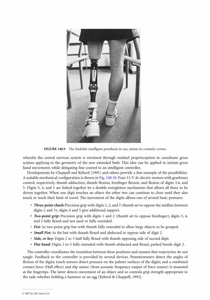
In a recent advance, intelligence is built into the swing-phase controller to adjust automatically forcadence variations (Fig. 140.9). A 4-bit microprocessor is used to adjust a needle valve, via a linear stepper
FIGURE 140.7 Schematic of operation of the Shoemaster shoe design system based on selection of a basis last froma database of model lasts. A database of styles is also employed to generate the upper patterns.
© 1997 by CRC Press LLC

motor, according to duration of the preceding swing phase [Zahedi, in press]. The unit is programmed bythe prosthetist to provide optimal damping for the particular amputee’s swing phase at slow, normal, andfast walking paces. Thereafter, the appropriate damping is automatically selected for any intermediate speed.
A Hierarchically Controlled Prosthetic Hand
Control of the intact hand is hierarchical. It starts with the owner’s intention, and an action plan isformulated based on knowledge of the environment and the object to be manipulated. For gross move-ments, the numerous articulations rely on “preprogrammed” coordination from the central nervoussystem. Fine control leans heavily on local feedback from force and position sensors in the joints andtactile information about loading and slip at the skin. In contrast, conventional prostheses depend onthe conscious command of all levels of control and so can be slow and tiring to use.
Current technology is able to provide both the computing power and transducers required to recreatesome of a normal hand’s sophisticated proprioceptive control. A concept of extended physiologic prop-rioception (EPP) was introduced for control of gross arm movement [Simpson & Kenworthy, 1973]
FIGURE 140.8 Pneumatic cylinder action in a swing phase controller. (Reprinted with permission from S. Zahedi,The Results of the Field Trial of the Endolite Intelligent Prosthesis, internal publication, Chas. A. Blatchford & Sons, U.K.)
© 1997 by CRC Press LLC
whereby the central nervous system is retrained through residual proprioception to coordinate grossactions applying to the geometry of the new extended limb. This idea can be applied to initiate grosshand movements while delegating fine control to an intelligent controller.
Developments by Chappell and Kyberd [1991] and others provide a fine example of the possibilities.A suitable mechanical configuration is shown in Fig. 140.10. Four 12-V dc electric motors with gearboxescontrol, respectively, thumb adduction, thumb flexion, forefinger flexion, and flexion of digits 3,4, and5. Digits 3, 4, and 5 are linked together by a double-swingletree mechanism that allows all three to bedriven together. When one digit touches an object the other two can continue to close until they alsotouch or reach their limit of travel. The movement of the digits allows one of several basic postures:
• Three-point chuck: Precision grip with digits 1, 2, and 3 (thumb set to oppose the midline betweendigits 2 and 3); digits 4 and 5 give additional support.
• Two-point grip: Precision grip with digits 1 and 2 (thumb set to oppose forefinger); digits 3, 4,and 5 fully flexed and not used or fully extended.
• Fist: As two-point grip but with thumb fully extended to allow large objects to be grasped.
• Small Fist: As fist but with thumb flexed and abducted to oppose side of digit 2.
• Side, or key: Digits 2 to 5 half fully flexed with thumb opposing side of second digit.
• Flat hand: Digits 2 to 5 fully extended with thumb abducted and flexed, parked beside digit 2.
The controller coordinates the transition between these positions and ensures that trajectories do nottangle. Feedback to the controller is provided by several devices. Potentiometers detect the angles offlexion of the digits; touch sensors detect pressure on the palmer surfaces of the digits; and a combinedcontact force (Hall effect) and slip sensor (from acoustic frequency output of force sensor) is mountedat the fingertips. The latter detects movement of an object and so controls grip strength appropriate tothe task–whether holding a hammer or an egg [Kyberd & Chappell, 1993].
FIGURE 140.9 The Endolite intelligent prosthesis in use, minus its cosmetic covers.
© 1997 by CRC Press LLC

The whole hand may be operated by electromyo-graphic signals from two antagonistic muscles in thesupporting forearm stump, picked up at the skin sur-face. In response to tension in one muscle, the handopens progressively and then closes to grip with anautomatic reflex. The second muscle controls themode of operation as the hand moves between thestates of touch, hold, squeeze, and release.
A Self-Aligning Orthotic Knee Joint
Knee orthosis are often supplied to resist knee flexionduring standing and gait at an otherwise collapsingjoint. The rigid locking mechanisms on these devicesare manually released to allow knee flexion duringsitting. Fitting is complicated by the difficulty ofattaching the orthosis with its joint accurately alignedto that of the knee. The simple diagram in Fig. 140.11shows how misplacement of a simple hinged orthosiswith a notional fixed knee axis would cause the cuffson the thigh and calf to press into the soft tissues ofthe limb (known as pistoning).
The human knee does not have a fixed axis, though,but is better represented as a polycentric joint. In asagittal (side) view, it is easy to conceptualize the ori-gin of these kinematics from the anatomy of the cru-ciate ligaments running crisscross across the joint,which together with the base of the femur and thehead of the tibia form a classic four-bar linkage. The
FIGURE 140.11 The problem caused by misplacement of a single-axis orthotic joint (a) is overcome by an orthosis(b) with a self-aligning axis. (The Laser system, courtesy of Hugh Steeper, Ltd., U.K.)
FIGURE 140.10 The Southampton hand prosthesiswith four degrees of freedom in a power grip. Anoptical/acoustic sensor is mounted on the thumb.(Reprinted from Kyberd and Chappell [1993], Fig. 1.)
© 1997 by CRC Press LLC
polycentric nature of the motion can therefore be mimicked by a similar geometry of linkage on theorthosis.
The problem of alignment still remains, however, and precision location of attachment points is notpossible when gripping through soft tissues. In one attempt to overcome this specific problem, the kneemechanism has been designed with not one but two axes (Fig. 140.11). The center of rotation is thenfree to self-align. This complexity of the joint while still maintaining the ability to fixate the knee andmeeting low weight requirements is only achieved by meticulous design in composite materials.
140.3 Summary
The field of prosthetics and orthotics is one where at present traditional craft methods sit alongside theapplication of high technology. Gradually, advanced technology is creeping into most areas, bringingvast improvements in hardware performance specifications and aesthetics. This is, however, an area wherethe clinical skills of the prosthetist and orthotist will always be required in specification and fitting andwhere many of the products have customized components. The successful applications of technology arethose which assist the professional to exercise his or her judgment, providing him or her with good toolsand means to realize a functional specification.
Since the demand for these devices is thankfully low, their design and manufacture are small scale interms of volume. This taxes the skills of most engineers, both to design the product at reasonable up-front costs and to manufacture it economically in low volume. For bespoke components, we are movingfrom a base of craft manufacture through an era when modularization was exploited to allow small-batch production toward the use of CAD. In the latter, the engineering design effort is then embodiedin the CAD system, leaving the prosthetist or orthotist to incorporate clinical design for each individualcomponent.
Specific examples of current applications have been described. These can only represent a small partof the design effort that is put into prosthetics and orthotics on a continuing basis, making advances inmaterials and electronics in particular available.
We are also aware that in the space available, it has not been possible to include a discussion of thevery innovative work that is being done in intermediate technology for the third world, for which theInternational Society of Prosthetics and Orthotics (address below) currently has a special working group.
Defining Terms
Biocompatability: Compatibility with living tissue, e.g., in consideration of toxicity, degradability, andmechanical interfacing.
CNC machining: Use of a computer numerically controlled machine.Cosmesis: Aesthetics of appearance.Ectromelia: Congenital gross shortening of the long bones of a limb.Functional prescription: A doctor’s prescription for supply of a device written in terms of its function
as opposed to embodiment.Neuroskeletomotor system: The skeletal frame of the body with the muscles, peripheral nerves, and
central nervous system of the spine and brain, which together participate in movement andstabilization of the body.
Rectified, rectification: Adjustment of a model of body shape to achieve a desirable load distributionin a custom-molded prosthesis or orthosis.
Soft tissues: Skin, fat, connective tissues, and muscles which, along with the hard tissues of bone, teeth,etc. and the fluids, make up the human body.
Transcutaneous: Passing through the skin.
© 1997 by CRC Press LLC

References
Chappell PH, Kyberd PJ. 1991. Prehensile control of a hand prosthesis by a microcontroller. J BiomedEng 13:363.
Childress DS. 1989. Control philosophies for limb prostheses. In J Paul, et al. (eds), Progress in Bioengi-neering, pp 210–215. New York, Adam Hilger.
Duncan JP, Mair SG. 1983. Sculptured Surfaces in Engineering and Medicine. Cambridge, England,Cambridge Univ. Press.
Houston VL, Burgess EM, Childress DS, et al. 1992. Automated fabrication of mobility aids (AFMA):Below-knee CASD/CAM testing and evaluation. J Rehabil Res Dev 29:78.
Kyberd PJ, Chappell PH. 1993. A force sensor for automatic manipulation based on the Hall effect. MeasSci Technol 4:281.
Lord M, Foulston J, Smith PJ. 1991. Technical evaluation of a CAD system for orthopaedic shoe-upperdesign. Eng Med Proc Instrum Mech Eng 205:109.
Reynolds DP, Lord M. 1992. Interface load analysis for computer-aided design of below-knee prostheticsockets. Med Biol Eng Comput 30:419.
Simpson DC, Kenworthy G. 1973. The design of a complete arm prosthesis. Biomed Eng 8:56.Zahedi S. In press, 1994. Evaluation and biomechanics of the intelligent prosthesis: A two-year study.
Orthop Tech.
Further Information
Bowker P, Condie DN, Bader DL, Pratt DJ (eds). Biomechanical Basis of Orthotic Management. Oxford,Butterworth-Heinemann, 1993.
Murdoch G, Donovan RG (eds). 1988. Amputation Surgery and Lower Limb Prosthetics. Boston, Black-well Scientific Publications.
Nordin M, Frankel V. 1980. Basic Mechanics of the Musculoskeletal System, 2d ed. Philadelphia, Lea &Febiger, 1980.
Smidt GL (ed). 1990. Gait in Rehabilitation. New York, Churchill-Livingstone.
Organizations
International Society of Prosthetics and Orthotics (ISPO), Borgervaenget 5,2100 Copenhagen Ø, Den-mark [tel (31) 20 72 60].
Department of Veterans Affairs, VA Rehabilitation Research and Development Service, 103 Gay Street,Baltimore, MD 21202-4051.
Rehabilitation Engineering Society of North America (RESNA), Suite 1540, 1700 North Moore Street,Arlington, VA 22209-1903.
© 1997 by CRC Press LLC