loopcare verification codes (0-99) - fairpoint communications
TRANSCRIPT

LoopCare Verification Codes (0-99) • VER 0: TEST OK • VER 0A: TEST OK • VER 0B: CPE or HIGH RESISTANCE OPEN • VER 0C: CPE or HIGH RESISTANCE OPEN • VER 0D: OPEN IN OR DSL TERM • VER 0E: OPEN OUT BALANCED OR DSL TERM • VER 0H: ROH DETECTED DURING TEST • VER 0L: NO FAULTS TO BENCHMARKED LENGTH • VER 0M: TEST OK MTU • VER 0P: PROBABLY TEST OK • VER 0R: TEST OK • VER 0T: OUT OF TOLERANCE CONDITION • VER 05: TEST OK - CHANNEL NOT TESTED • VER 6: BUSY-SPEECH • VER 11: CROSS TO WORKING PAIR- FAULT • VER 12: AC FEMF FAULT • VER 13: HAZARDOUS POTENTIAL • VER 14: CROSS TO WORKING PAIR: MARGINAL • VER 15: DC FEMF MARGINAL • VER 16: AC FEMF MARGINAL • VER 17: RESISTIVE FAULT AND DC FEMF • VER 18: OPEN OUT AND CROSS • VER 21: GROUND FAULT • VER 22: SHORT FAULT • VER 23: SWINGING RESISTANCE: FAULT • VER 24: SWINGING RESISTANCE: MARGINAL • VER 25: SHORT AND GROUND • VER 26: MDF TEST RECOMMENDED- LOW
RESISTANCE • VER 27: DC RESISTANCE- MARGINAL • VER 28: SHORT OR GROUND • VER 3: OPEN IN • VER 30: SWITCH COMMON EQUIP BAD • VER 31: INVALID LINE CIRCUIT • VER 32: CANNOT DRAW DIAL TONE • VER 33: CAN'T BREAK DIAL TONE • VER 34: POSSIBLE INVALID ACCESS • VER 35: OPEN IN AND CROSS

• VER 36: LINE CIRCUIT AND DIAL TONE PROBLEM • VER 37: DIAL TONE BURST DETECTED • VER 38: POSSIBLE CO WIRING ERROR • VER 39: CO EQUIP BAD - ISTF BAD - LINE CARD BAD
- PROTOCOL HANDLER BAD • VER 40: CO EQUIP SUSPECT • VER 41: OPEN OUT BALANCED • VER 42: OPEN OUT IN CABLE • VER 43: HIGH RESISTANCE OPEN • VER 44: OPEN OUT 2-PARTY OR BRIDGE LIFTERS • VER 45: OPEN OUT - NEAR DROP • VER 46: OPEN ON PREMISES • VER 47: OPEN IN REMOTE TERMINAL • VER 48: T1 FACILITY BAD • VER 50: COT CHANNEL UNIT SUSPECT • VER 51: CO BATTERY ON PAIR GAIN SYSTEM • VER 52: INVALID PAIR GAIN CO SIGNATURE • VER 53: PAIR GAIN TEST ACCESS FAILURE -
POSSIBLE BUSY CONDITION • VER 54: PAIR GAIN SYSTEM FAILURE • VER 55: PAIR GAIN CHANNEL FAILURE • VER 56: BAD PAIR GAIN COT CHANNEL UNIT • VER 57: BAD RT CHANNEL UNIT • VER 58: BAD COT AND RT CHANNEL UNITS • VER 59: RT CHANNEL UNIT SUSPECT • VER 60: BUSY PACKET • VER 61: LINE IN USE • VER 63: CRAFT ACTION • VER 71: RECEIVER OFF HOOK (ROH) • VER 72: MDF TEST RECOMMENDED- PERMANENT
SIGNAL • VER 73: LINE IN USE OR PERMANENT SIGNAL • VER 74: PERMANENT SIGNAL • VER 75: SHORT - PROBABLY ROH • VER 80: DIAL OK • VER 81: DIAL NOT OK • VER 90: C-MESSAGE NOISE • VER 91: INVALID PBX SIGNATURE • VER 92: INVALID AC SIGNATURE • VER 93: POOR BALANCE • VER 95: RESISTIVE FAULT AND OPEN

• VER 96: MARGINAL BALANCE • VER 97: DERIVED PR NOT TESTED-PHYSICAL PR
NOT SERVED • VER 98: ANALYSIS OF FULL RESULTS NEEDED • VER 99: MULTIPLE FAULTS DETECTED
VER 0: TEST OK
Overview
No obvious trouble was detected on the line. However, there may still be a problem with parts of the loop that were not tested. In general, when the system tests OK, there is no problem indicated by any of the detailed results. For metallic testing, the DC resistances and voltage are within the acceptable range, the AC signature is valid, and a loop length is reported. For higher-layer testing, such as Broadband and VoIP, the reported statistics and/or graphics indicate that each of the tested layers and network elements is functioning normally. For more information, see the section of the Test Request Guide that corresponds to the particular test that was run,
Example
VER 0: TEST OK
CRAFT: DC SIGNATURE MLT: DC SIGNATURE AC SIGNATURE KOHMS VOLTS KOHMS VOLTS KOHMS RNGRS 3500 T-R 3500 T-R 9 1 T-R 3500 0 T-G 3500 0 T-G 4500 T-G 3500 0 R-G 3500 0 R-G 4600 R-G
Additional Information
This example is a TEST OK for a single party line. Note the CRAFT and LoopCare DC signatures show high resistances (3500 K ohms) and low voltage (0 Volts). The AC signature indicates the presence of a ringer tip to ring. The central office check indicates that the line circuit arrangement of battery and ground was valid and LoopCare was able to draw and break dial tone properly. In addition, the capacitive balance (100%) and the longitudinal balance (65 DB) were both good. Finally, the length of the loop is given as the last piece of information about the line.
Also take note that you may occasionally get a TEST OK message if there is a keyset on the customer's line.
bPON Feature
VER 0: DROP TEST OK
A bPON test on a customer drop detected no obvious problems.
VER 0A: TEST OK

Overview
VER 0A indicates that either a FULL(X) or LOOP(X) test request was run and the signatures returned show an ADSL served line.Testing indicates that the line is OK. One of the following summary messages appears.
ADSL C.O. SPLITTER SIGNATURE FOUND NON SIGNATURED SPLITTER DETECTED
Example
VER 0A: TEST OK
ADSL C.O. SPLITTER SIGNATURE FOUND
CRAFT: DC SIGNATURE MLT: DC SIGNATURE AC SIGNATURE
KOHMS VOLTS KOHMS VOLTS KOHMS RNGRS
3500 T-R 3500 T-R 15 YES T-R
3500 0 T-G 3500 0 T-G 2000 T-G
3500 0 R-G 3500 0 R-G 2000 R-G
BALANCE
CAP 100 % LOOP LENGTH = 9100 FT
LONG 65 DB
VER 0B: CPE or HIGH RESISTANCE OPEN
Overview
LoopCare did not detect any obvious trouble on the line, however, it did find either a CPE termination or a high resistance open on the line. In most cases this will indicate that it is a CPE termination. The remote possibility exists however, that it could be a high resistance open problem.
LoopCare sets VER 0B when it finds the termination through the Breakthrough CPE Detection tests. See the System Description for more information on this feature.

VER 0C: CPE or HIGH RESISTANCE OPEN
Overview
LoopCare did not detect any obvious trouble on the line, however, it did find either a CPE termination or a high resistance open on the line. In most cases this will indicate that it is a CPE termination. The remote possibility exists however, that it could be a high resistance open problem.
Additional Information
This example is a TEST OK for a single party line, Centrex lines, Key Systems, and loop-start PBX lines with CPE termination. These lines may or may not have line records. Note the CRAFT and LoopCare DC signatures show high resistances (3500 Kohms) and low voltage (0 Volts). The message "CPE or HIGH RESISTANCE OPEN" is shown because of the remote possibility that there is a high resistance open condition on the line. It should be noted that a ringer configuration test is not performed here.
The central office check indicates that the line circuit arrangement of battery and ground was valid and LoopCare was able to draw and break dial tone properly. In addition, the capacitive balance (100%) and the longitudinal balance (65 DB) were both good. Finally, the length of the loop is given as the last piece of information about the line.
VER 0D: OPEN IN OR DSL TERM
Overview
LoopCare has detected either an open condition or an xDSL termination with an AC signature similar to that of an open condition on the loop. It has been determined that the open is in or very close to the Central Office. There is an offset value (in feet) stored in the computer for each test unit. If the open is detected within this offset limit, it is considered an open in. An open is a physical break in the line.
Example
VER 0D: OPEN IN OR DSL TERM
CRAFT: DC SIGNATURE MLT: DC SIGNATURE AC SIGNATURE KOHMS VOLTS KOHMS VOLTS KOHMS 3500 T-R 3500 T-R 2000 T-R 3500 0 T-G 3500 0 T-G 1267 T-G 3500 0 R-G 3500 0 R-G 1038 R-G

VER 0E: OPEN OUT BALANCED OR DSL TERM
Overview
LoopCare has detected either an open condition or an xDSL termination with an AC signature similar to that of an open condition on the loop. It has been determined that the open is out of the Central Office. The capacitive balance, which indicates the difference between the capacitance in each side of the line, is 99% or better.
Example
VER 0E: OPEN OUT BALANCED OR DSL TERM
CRAFT: DC SIGNATURE MLT: DC SIGNATURE AC SIGNATURE KOHMS VOLTS KOHMS VOLTS KOHMS 3500 T-R 3500 T-R 2000 T-R 3500 0 T-G 3500 0 T-G 1267 T-G 3500 0 R-G 3500 0 R-G 1038 R-G
VER 0H: ROH DETECTED DURING TEST
Overview
VER 0H denotes that an open loop condition was found during testing and that an ROH condition occurred during the test. This is an indication that there is a undetectable CPE on the loop and that it went off-hook during testing. This condition could be caused by a FAX or Answering machine or a human.
When this condition occurs, the data from the Central Office portion of the test is discarded because of the unexpected short on the loop. Run a CO test to determine the validity of the line circuit and dial tone. If the CO test passes, treat the VER 0H same as a VER 0. Running a LOOP test by itself results in a VER 41 or other open VER code. This is normal. The loop should be considered terminated with an undetectable CPE.
Example
VER 0H: ROH DETECTED DURING TEST
USE CO REQ FOR LINE CKT & DIALTONE

VER 0L: NO FAULTS TO BENCHMARKED LENGTH
Overview
When a test returns a VER41 (OPEN OUT BALANCED) for a POTS test (narrowband only) and the loop length is within tolerance of the BENCH result in the BMDB, the VER code is changed to 0L.
For information on loop length tolerance, see the BMDB section of the OA&M Guide .
Example
VER 0L: TEST OK NO FAULTS TO BENCHMARKED LENGTH
VER 0M: TEST OK MTU
Overview
VER 0M (zero M) is used by LMOS on the TR and DMLT masks and by ADSL Pre-qualification tests to indicate a TEST OK condition on a line that has a Maintenance Termination Unit (MTU). In LMOS, this VER code is used for flowthrough.
EXAMPLE
VER 0M: TEST OK MTU
VER 0P: PROBABLY TEST OK
Overview
LoopCare has analyzed a marginal DC fault on the line under test and determined that there is a high probability that it does not affect service. This VER code should be treated as a TEST OK and an attempt should be made to close out any trouble report.
EXAMPLE
VER 0P: PROBABLY TEST OK

VER CODE MAPPED FROM VER <CODE>
VER 0R: TEST OK
Overview
This is an otherwise Test OK result where the results are sufficiently different from the BENCH result in the Benchmark Database to remove existing data about the circuit. Candidate VER CODES for rebenching are all "0" VER codes and 41 and 46. The conditions under which a circuit is rebenched can be found in the BMDB Re-Bench section of the System Description and the BMDB section of the OA&M Guide.
Example
VER 0R : TEST OK BENCHMARK DATA STORED
CRAFT: DC SIGNATURE MLT: DC SIGNATURE AC SIGNATURE
KOHMS VOLTS KOHMS VOLTS KOHMS RNGRS
3500 T-R 3500 T-R 9 Y T-R
3500 0 T-G 3500 0 T-G 2000 T-G
3500 0 R-G 3500 0 R-G 2000 R-G
VER 0T: OUT OF TOLERANCE CONDITION
Overview
This VER code is displayed on the TV mask when the FULL/LOOP test result for a TN differs from the Benchmark by a user-configured pre-set threshold. Measured parameters include Loop Length, Capacitive Balance, and any of the three AC Impedances.
One of the following summary messages may also appear with VER 0T:
• AC IMPEDANCE IS OUT OF TOLERANCE
• CAPACITIVE BALANCE IS OUT OF TOLERANCE
Additional Information
Refer to the LoopCare Test Requests User Guide for detailed information and procedures.

VER 05: TEST OK - CHANNEL NOT TESTED
Alternative
With the Reclassify VER Code 5x feature turned on, the message is as follows:
TEST OK - CHANNEL TESTS IGNORED
Label
VER_05 (zero five) is applicable to all switches and applies to both integrated and universal DLC loops. It indicates that all metallic tests passed, but that the channel test was either not made, didn't complete in time or the returned results did not match the acceptable signatures. It does not mean that the channel is bad. For IDLC in 5ESS switches, it may be an indication that there may be a shortage of transmission test facility (TTF) responders (The TTF performs the ISLC channel tests). If the VER 55-58 reclassification feature is enabled, VER 55-58 codes will be changed to VER 05 with a summary message of TEST OK - CHANNEL TESTS IGNORED. Use the V55 override to disable this feature.
Exclusions
This VER Code applies to the LTF, LTS, DCTU and CMU test heads. With this VER Code, the RSA may be able to arrange a front end close out as no trouble
affecting the loop has been identified.
Example
VER 05 : TEST OK - CHANNEL TESTS IGNORED
CRAFT: DC SIGNATURE MLT: DC SIGNATURE AC SIGNATURE
KOHMS VOLTS KOHMS VOLTS KOHMS RNGRS
3500 T-R 3500 T-R 11 YES T-R
3500 0 T-G 3500 0 T-G 1959 T-G
3500 0 R-G 3500 0 R-G 1962 R-G
BALANCE CAP 100 % LONG 65 DB
VER 6: BUSY-SPEECH

Overview
The system found the line busy with what it identifies as conversation on the line. Testing is stopped at this point.
Additional Information
Hold the trouble until the customer is finished talking on the line, then retest the line with the LoopCare.
See Also
VER codes related to VER 6 (BUSY- SPEECH) are listed below:
VER 61 LINE IN USE
VER 11: CROSS TO WORKING PAIR- FAULT
Overview
DC foreign voltage (battery) was detected on the line. This can be caused by DC current flowing from one line to another, as can happen if exposed wires from the lines touch or come close. The side of the line that is crossed usually has a low resistance to ground. A cross is usually a cable trouble, that is where lines are most likely to come in contact.
Example
VER 11 :CROSS TO WORKING PAIR: RING SIDE MODERATE BATTERY R-G - 9 V
CRAFT: DC SIGNATURE MLT: DC SIGNATURE AC SIGNATURE
KOHMS VOLTS KOHMS VOLTS KOHMS RNGRS
3500 T-R 3500 T-R 9 1 T-R
3500 0 T-G 3500 0 T-G 4500 T-G
3500 0 R-G 3500 0 R-G 4600 R-G
VER 11: CROSS TO WORKING PAIR: RING SIDE
MODERATE BATTERY R-G - 9 V
CRAFT: DC SIGNATURE MLT: DC SIGNATURE AC SIGNATURE
KOHMS VOLTS KOHMS VOLTS KOHMS RNGRS
1676 T-R 3500 T-R 9 Y T-R

1633 T-G 2801 0 T-G 117 T-G
389 -9 R-G 415 -46 R-G 98 R-G
Additional Information
LoopCare identifies a cross in the following manner:
• First the LoopCare DC SIGNATURE must fit the thresholds given below:
RESISTANCE VOLTAGE > 10 K T-R > 1 K T-G > 20 V T-G and/or > 1 K R-G > 20 V R-G
• If the LoopCare DC SIGNATURE indicates a CROSS, then the CRAFT DC VOLTAGE is calculated. If the CRAFT voltage is greater than the locally determined fault threshold, then this condition is a CROSS FAULT (VER 11).
• If the CRAFT VOLTAGE is below the locally established fault value, then the condition is a CROSS MARGINAL (VER 14).
The locally settable CRAFT voltage threshold is adjusted from the SAM mask via the CT request. The default value is -6 volts.
Note the relationships between the LoopCare DC VOLTAGE, the LoopCare DC RESISTANCE, and the CRAFT DC VOLTAGE. The CRAFT DC VOLTAGE is less than the LoopCare DC VOLTAGE (-9 to -46 respectively R-G). This difference is due to the way the measurements are made to calculate each voltage. Simply stated the LoopCare DC VOLTAGE gives you the actual amount of voltage present on the line. The CRAFT DC VOLTAGE gives you the amount of voltage on the line that is measured across the DC resistance. It is actually what a craft meter would see if the measurement was made next to the Loop Test System of LoopCare. The lower the resistance the more CRAFT DC VOLTAGE will be found. The higher the resistance the less CRAFT DC VOLTAGE will be found. Therefore, as the DC resistance approaches 0, the CRAFT and LoopCare DC VOLTAGE values will be closer.
A cross is usually a cable problem. This makes sense when you realize the most likely place for two telephone pairs to come in contact is in the cable where they are bundled together.
See Also
VER codes related to VER 11 (CROSS FAULT) are listed below:
VER 14 (CROSS MARGINAL) VER 15 (DC FEMF MARGINAL) VER 17 (RESISTIVE FAULT AND DC FEMF) VER 18 (OPEN OUT AND CROSS)
VER 12: AC FEMF FAULT
Overview

An AC foreign voltage greater than the locally determined fault value (default value is 25 volts) was detected on the line. The locally settable AC foreign voltage (FEMF) value is changed from the SAM transaction via the CT request.
This condition could be caused by a cross with a power line, or AC induction due to telephone lines being close to power lines.
Additional Information
If this trouble is dispatched to a repair person, that person should be advised to use caution when working on the line. Anytime there is AC voltage on the line there is a potential danger.
See Also
VER codes related to VER 12 (AC FEMF FAULT) are listed below
VER 13 HAZARDOUS POTENTIAL VER 16 AC FEMF MARGINAL
VER 13: HAZARDOUS POTENTIAL
Overview
The preliminary LoopCare tests on the line indicate that there is a potentially dangerous amount of voltage on the line ( > 150 Volts DC or 53 Volts rms AC). When LoopCare identifies this condition, it will stop testing.
Additional Information
Hazardous potential could be caused by a high voltage surge on a line due to a number of conditions, including a cross with a power line or lightning striking the line. The LoopCare equipment will remain attached to the line, but all further test requests will only check to see if the Hazardous Potential is still present.
This condition could be potentially dangerous. It is important that you warn any craft person working with the line of the possible hazard.
Example
VER 13: HAZARDOUS POTENTIAL DANGER- ADVISE SUPERVISOR USE EXTREME CAUTION
See Also
VER codes related to VER 13 (HAZARDOUS POTENTIAL) are listed below:
VER 12 AC FEMF FAULT VER 16 AC FEMF MARGINAL

VER 14: CROSS TO WORKING PAIR: MARGINAL
Overview
LoopCare detected the presence of DC foreign voltage (also called foreign battery) below the fault level (marginal) on the line. This is caused by DC current flowing on the line from another telephone line. The source of the voltage is the CO battery of the other line. The battery can be present tip to ground, ring to ground or both. The side of the line that has the battery will usually have low resistance (a ground).
Additional Information
LoopCare identifies a cross in the following manner:
First the LoopCare DC SIGNATURE must fit the thresholds given below:
RESISTANCE VOLTAGE > 10 K T-R > 1 K T-G > 20 V T-G and/or > 1 K R-G > 20 V R-G
• If the LoopCare DC SIGNATURE indicates a CROSS, then the CRAFT DC VOLTAGE is calculated. If the CRAFT voltage is greater than the locally determined fault threshold, then this condition is a CROSS FAULT (VER 11).
• If the CRAFT VOLTAGE is below the locally established fault value, then the condition is a CROSS MARGINAL (VER 14).
• The locally settable CRAFT voltage threshold is adjusted from the CRSB mask. The default value is -6 volts.
Note the relationships between the LoopCare DC VOLTAGE, the LoopCare DC RESISTANCE, and the CRAFT DC VOLTAGE. The CRAFT DC VOLTAGE is less than the LoopCare DC VOLTAGE (-3 to -46 respectively R-G). This difference is due to the way the measurements are made to calculate each voltage. Simply stated the LoopCare DC VOLTAGE gives you the actual amount of voltage present on the line. The CRAFT DC VOLTAGE gives you the amount of voltage on the line that is measured across the DC resistance. Actually, this measurement is what the craft meter would see if the measurement was made next to the Loop Test System of LoopCare. The lower the resistance the more CRAFT DC VOLTAGE will be found. The higher the resistance the less CRAFT DC VOLTAGE will be found. Therefore, as the DC resistance approaches 0, the CRAFT and LoopCare DC VOLTAGE values will be closer.
A cross is usually a cable problem. This makes sense when you realize the most likely place for two telephone pairs to come in contact is in the cable where they are bundled together.
See Also
VER codes related to VER 14 (CROSS MARGINAL) are listed below:
VER 11 (CROSS FAULT) VER 15 (DC FEMF MARGINAL)

VER 17 (RESISTIVE FAULT AND DC FEMF) VER 18 (OPEN OUT AND CROSS)
VER 15: DC FEMF MARGINAL
Overview
The LoopCare DC VOLTAGE detected on the line was between -8 and -20 volts. In addition, no other problems are found on the line. Note that while the CRAFT DC VOLTAGE values will be displayed in the summary, it is the LoopCare DC VOLTAGE values that identify this condition.
Additional Information
A VER 15 (DC FEMF MARGINAL) is probably a cable trouble. This condition is very similar to both CROSS TO WORKING PAIR conditions (VER 14 and 15) since it indicates that foreign DC battery is on the line. The distinction of this condition is that the LoopCare DC VOLTAGE does not match the expected voltage of the LoopCare DC SIGNATURE for a cross. LoopCare expects to see an LoopCare DC VOLTAGE greater than 20 volts in order to call the trouble a cross. In this case the LoopCare DC VOLTAGE will never be greater than 20 volts.
Basically, VER 15 (DC FEMF MARGINAL) is usually a cross-like condition with a small amount of voltage on the line. The LoopCare DC RESISTANCE on the side of the line with the voltage, while below 3500 K ohms, is usually close to or above 1000 K ohms. DC resistances in this range will result in some voltage on the line, but not much.
Because of the particular DC resistance range and the low amount of battery on the line, this condition might be difficult for a craft person to locate in the field. Follow local procedures when handling this type of trouble.
Example
VER15: DC FEMF MARGINAL LONGITUDINAL NOISE 93 DB
CRAFT: DC SIGNATURE MLT: DC SIGNATURE AC SIGNATURE KOHMS VOLTS KOHMS VOLTS KOHMS RNGRS 2095 T-R 3500 T-R 9 Y T-R 2095 0 T-G 3500 0 T-G 2000 T-G 1378 -1 R-G 1716 -19 R-G 2000 R-G
See Also
VER codes related to VER 15 (DC FEMF MARGINAL) are listed below:
VER 11 CROSS FAULT VER 14 CROSS MARGINAL VER 17 RESISTIVE FAULT AND DC FEMF VER 18 OPEN OUT AND CROSS

VER 16: AC FEMF MARGINAL
Overview
An AC foreign voltage less than the locally determined fault value (default value is 25 volts) but greater than the display threshold (15 volts). The locally settable AC foreign voltage (FEMF) value is changed from the SAM transaction via the CT request.
This condition could be caused by a cross with a power line, or AC induction due to telephone lines being close to power lines.
Additional Information
While there is not a great deal of AC voltage on the line, it may be appropriate to inform the repair person that there is some foreign AC voltage on the line and to use caution.
See Also
VER codes that are related to VER 16 (AC FEMF MARGINAL) are listed below:
VER 12 AC FEMF FAULT VER 13 HAZARDOUS POTENTIAL
VER 17: RESISTIVE FAULT AND DC FEMF
Overview
LoopCare has detected a stable resistive trouble (short or ground) that is below the locally established fault threshold. In addition, the LoopCare DC VOLTAGE on the line is greater than 8 volts.
Additional Information
Many of the troubles that are grouped under this VER code are CROSS-like conditions that did not match the LoopCare DC SIGNATURE of a cross for one of the following reasons:
• The T-R LoopCare resistance was > 10 K
• The T-G and R-G LoopCare resistance was < 1 K
• The LoopCare voltage on the line was > -20 V
Another case may be that the VER condition may be a LINE IN USE condition or a PERMANENT SIGNAL condition that did not match the LoopCare DC SIGNATURE for those conditions. To check for this possibility, match the LoopCare DC SIGNATURE against what is expected for a

LINE IN USE or a PERMANENT SIGNAL condition. If the values are very close, you might suspect that you have such a condition.
See Also
VER codes that are related to VER 17 (RESISTIVE FAULT AND DC FEMF) are listed below:
VER 11 CROSS FAULT VER 14 CROSS MARGINAL VER 15 DC FEMF MARGINAL VER 21 GROUND FAULT VER 22 SHORT FAULT VER 25 SHORT AND GROUND VER 61 LINE IN USE VER 73 LINE IN USE OR PERMANENT SIGNAL VER 74 PERMANENT SIGNAL
VER 18: OPEN OUT AND CROSS
Overview
LoopCare has detected an open on the line and has determined that the open is out of the CO. In addition, a cross to a working pair has been detected.
If the line is served by a digital loop carrier system (DLCS) and is tested by a Remote Measurement Unit (RMU), LoopCare has determined that the open is out of the Remote Terminal (RT) of the carrier system.
Additional Information
Usually, when there is more than one trouble on the line, they are related in some way. One likely situation is that there is an open in the cable and the open wires in the cable are crossed. Here, the open is causing the cross to working pair condition.
This VER code is likely to reflect cable trouble. One likely possibility is that the line is open and one or both of the open sides are crossed with another pair. This could happen if the cable were cut and the open ends were contacting each other.
If the line is served by a DLCS and tested by an RMU, the distance provided by LoopCare is measured from the RT of the DLCS. Since the "cable" of a carrier-system-served line is part of the carrier system, the fault would necessarily be between the RT and the station for such lines.
See Also
The following VER codes are related to VER 18 (OPEN OUT AND CROSS):
VER 11 CROSS FAULT VER 14 CROSS MARGINAL

VER 41 OPEN OUT BALANCED VER 42 OPEN OUT CABLE VER 45 OPEN OUT NEAR DROP
VER 21: GROUND FAULT
Overview
This condition indicates that the LoopCare DC RESISTANCE to ground (ring-ground and/or tip-ground) is below the locally settable fault threshold. The default threshold for a ground fault is 150 K ohms. On a normal line the LoopCare DC RESISTANCE to ground is high (usually > 3500 K ohms).
LoopCare will not display the AC SIGNATURE with DC resistance to ground less than 50 Kohms. With this fault condition, VER code 21 will be displayed with either an open or a termination.
Additional Information
A ground condition can be caused when the insulation between wires of a pair is worn down and the wires either come in contact with or establish an electrical path to a grounded object. Most grounds occur outside of the central office. You can assume that the ground is out of the central office on an LoopCare VER 21. When the resistances are very low the trouble may be in or out of central office. LoopCare, however, realizes this and in such cases recommends that you run an MDF test to sectionalize the trouble.
On a regular plain old telephone line (POTS) the only valid path to ground is in the central office line circuit on the tip and ring sides of the line. Any other path to ground, unless specifically identified as being caused by CO, Outside Plant, or Termination equipment, is a trouble.
When the customer goes off-hook the central office line circuit puts battery on the line. This battery goes out from the CO on the ring side of the line and flows between tip and ring at the receiver (ROH). It then completes the loop by returning to the ground in the central office on the tip side of the line. If there is a path to ground at any other point in the circuit then some or all of the current will leak out of the loop. How much current leaks out of the loop depends on the severity of the ground. The harder the ground the more current will leak out and the more severe the trouble.
Sometimes the pair is grounded to another working telephone line. When this happens we can identify this if the battery from the other pair is detected. This will happen if we are crossed to the ring-side of the other pair. Remember the battery is found on the ring side of the line. When this happens it is called a cross to working pair. For more information see the module on VER 11 (CROSS TO WORKING PAIR FAULT) or VER 14 (CROSS TO WORKING PAIR MARGINAL).
For an ISDN line with an NT1, when there is a hard fault on one side, a ghost fault can appear on the other side. We will mask the light ghost fault and only display the hard fault. If there is a double sided fault, only the hard fault will be displayed and the other fault masked. Therefore, in this case, when the fault which was displayed has been fixed and a retest is run, a fault could appear on the other side. This is because there was initially a double sided fault.
See Also
VER codes related to VER 21 (GROUND FAULT) are listed below:
VER 17 RESISTIVE FAULT AND DC FEMF VER 22 SHORT FAULT VER 23 SWINGING RESISTANCE FAULT VER 24 SWINGING RESISTANCE MARGINAL VER 25 SHORT AND GROUND VER 27 DC RESISTANCE MARGINAL VER 95 RESISTIVE FAULT AND OPEN
VER 22: SHORT FAULT
Overview
This condition indicates that the LoopCare DC resistance tip to ring is below the locally settable fault threshold. The default threshold for a short fault is 150 kohms. On a normal line the LoopCare DC resistance tip to ring is high (usually > 3500 kohms).
LoopCare will not display the AC SIGNATURE with short less than 50 Kohms. With this DC fault condition, VER code 22 will be displayed with either an open or a termination.
Additional Information
A short condition can be caused when the insulation between wires of a pair is worn down and the wires either come in contact with or establish an electrical path with each other. Most shorts occur outside of the central office. You can assume that the short is out of the central office on an LoopCare VER 22. When the resistances are very low the trouble may be in or out of central office. LoopCare, however, realizes this and in such cases recommends that you run an MDF test to sectionalize the trouble.
A short allows a path for the central office current to go between tip and ring. The only valid path between tip and ring is at the customer's phone when it is off-hook. Any other short, unless specifically identified as being caused by CO, outside plant, or termination equipment, is a trouble. When the customer goes off-hook (ROH), the central office line circuit puts battery on the line. This battery goes out from the central office on the ring side of the line and flows between tip and ring at the receiver. It then completes the loop by returning to the ground in the central office on the tip side of the line. If there is a short at any other point in the circuit, some or all of the current will not reach the receiver but will take the shorter path to the central office ground. How much current takes this shorter path depends on the severity of the short. The harder the short the more current will take this path between tip and ring instead of the short at the receiver.
See Also VER 17 RESISTIVE FAULT AND DC FEMF VER 21 GROUND FAULT VER 25 SHORT AND GROUND VER 26 MDF TEST RECOMMENDED- LOW RESISTANCE VER 27 DC RESISTANCE MARGINAL

VER 71 ROH VER 75 SHORT - PROBABLY ROH VER 95 RESISTIVE FAULT AND OPEN
VER 23: SWINGING RESISTANCE: FAULT
Overview
LoopCare detects a ground below the locally established fault value but greater than 10 K ohms. A SOAK test is then run on the line to determine the stability of the ground (determines whether the DC resistances of the ground vary with time). If the ground is not stable (a swinging condition), then LoopCare will display VER 23.
LoopCare will not display the AC SIGNATURE with DC faults less than 50 Kohms. With this fault condition, VER code 23 will be displayed with either an open or a termination.
Additional Information
The SOAK test is used to determine the stability of resistive troubles to ground. The SOAK test is run when the LoopCare DC RESISTANCE to ground (T-G or R-G) is between 10 and 1000 K ohms. The SOAK test is not run if there is a short or cross condition identified. Sometimes the ground problem may be due to some temporary condition like a wet cable. As the cable dries, the trouble becomes less severe.
The SOAK test puts voltage on the line and then takes six measurements of the DC resistance. If the last of the six measurements is 20% greater than the DC resistance measured before the SOAK test, LoopCare determines that the ground is not stable (SWINGING). If the largest of the six measurements is greater than 2000 K ohms LoopCare indicates that the trouble has come clear (DRIED OUT).
See Also
VER codes related to VER 23 (SWINGING RESISTANCE- FAULT) are listed below:
VER 21 GROUND VER 24 SWINGING RESISTANCE- MARGINAL
VER 24: SWINGING RESISTANCE: MARGINAL
Overview

LoopCare detects a ground above the locally established fault value but less than 1000 K ohms. A SOAK test is then run on the line to determine the stability of the ground (determines whether the DC resistances of the ground vary with time). If the ground is not stable (a swinging condition), then LoopCare will display VER 24.
Additional Information
The SOAK test is used to determine the stability of resistive troubles to ground. The SOAK test is run when the LoopCare DC RESISTANCE to ground (T-G or R-G) is between 10 and 1000 K ohms. The SOAK test is not run if a short or a cross condition is identified. Sometimes the ground problem may be due to some temporary condition like a wet cable. As the cable dries, the trouble becomes less severe.
The SOAK test puts voltage on the line and then takes six measurements of the DC resistance. If the last of the six measurements is 20% greater than the DC resistance measured before the SOAK test, LoopCare determines that the ground is not stable (SWINGING). If the largest of the six measurements is greater than 2000 K ohms LoopCare indicates that the trouble has come clear (DRIED OUT).
See Also
VER codes related to VER 24 (SWINGING RESISTANCE- MARGINAL) are listed below:
VER 21 GROUND FAULT VER 23 SWINGING RESITANCE- FAULT VER 27 DC RESISTANCE MARGINAL
VER 25: SHORT AND GROUND
Overview
This VER code indicates that LoopCare has detected a short fault (DC resistance tip to ring below the local fault threshold). In addition, one or both of the ground DC resistances was below the local fault threshold. On a normal line all the LoopCare DC resistances should be high (usually > 3500 K ohms).
LoopCare will not display the AC SIGNATURE with DC faults less than 50 Kohms. With this fault condition, VER code 25 will be displayed with either an open or a termination.
Additional Information
A short or ground condition can be caused when the insulation on the telephone wires is worn or becomes wet, exposing the wires. Most grounds and shorts occur outside of the central office. You can assume that such a condition is out of the central office on an LoopCare VER 25. When the resistances are very low the trouble may be in or out of central office. LoopCare, however, realizes this and in such cases recommends that you run an MDF test to sectionalize the trouble.
A short allows a path for the central office current to go between tip and ring. A ground is a source that absorbs the central office current. The only valid path between tip and ring is at the customer's phone when it is off-hook. The only valid grounds are the tip and ring grounds in the

central office line circuit. Unless the line records indicate that there is CO, Outside Plant, or Termination equipment that also cause low DC resistance, any other short or ground is a trouble.
When the customer goes off-hook the central office line circuit puts battery on the line. This battery goes out from the CO on the ring side of the line and flows between tip and ring at the receiver (ROH). It then completes the loop by returning to the ground in the central office on the tip side of the line. If there is a short at any other point in the circuit then some or all of the current will not reach the receiver but will take the shorter path to the CO ground. Likewise, if there are any other path to ground other than the ground in the CO, the current will leak off the line before it can complete the circuit. How much current leaks from the circuit at the ground or short fault depends on the severity of the resistive fault. The harder the problem the more current will leave the circuit.
See Also
VER codes related to VER 25 (SHORT AND GROUND) are listed below:
VER 21 GROUND FAULT VER 22 SHORT FAULT VER 27 DC RESISTANCE MARGINAL
VER 26: MDF TEST RECOMMENDED- LOW RESISTANCE
Overview
This VER code indicates that LoopCare has detected a short and/or ground(s) on the line below the locally settable fault threshold. The default threshold for a resistive fault is 150 kohms. In addition, the LoopCare DC resistance of one or more of the troubles was low enough that LoopCare could not determine if the trouble was in or out of the central office. Therefore, LoopCare recommends an MDF test to sectionalize the problem in or out of the C.O.
The thresholds that determine whether or not the MDF test is recommended are listed below. These thresholds represent the LoopCare DC resistance after the test trunk resistances are subtracted. This subtraction is done by LoopCare and is not displayed for the user. It is possible that this VER code could be set even if the values in the LoopCare DC resistances are greater than those given below.
THRESHOLD FOR RECOMMENDING MDF TEST
Any one of these values could set VER 26.
T-R < 0.1 kohm
T-G < 0.07 kohm
R-G < 0.07 kohm

On a normal line all the LoopCare DC resistances should be high (usually > 3500 kohms).
Additional Information
The LoopCare DC resistance values may be recorded for each central office where an MDF test could be used. This would supplement the decision LoopCare makes when it sets VER 26.
If the displayed LoopCare DC resistance value is between 0 and 100 ohms, LoopCare recognizes the trouble as a short that may be within or outside the central office (VER 26) and recommends an MDF test to sectionalize the trouble. If the resistance value is between 100 ohms and 3.4 kohms, LoopCare may determine that the trouble stems from an ROH condition (VER 71) or requires manual confirmation of this (VER 75). If the resistance value is above 3.4 kohms, LoopCare classifies the problem as a short between the central office and the subscriber (VER 22).
See Also VER 21 GROUND FAULT VER 22 SHORT FAULT VER 25 SHORT AND GROUND VER 71 ROH VER 75 SHORT - PROBABLY ROH
VER 27: DC RESISTANCE- MARGINAL
Overview
This VER code indicates that LoopCare has detected a short or a ground condition and the LoopCare DC RESISTANCE was above the locally settable fault threshold, but below 1000 K ohms. This is a marginal condition, not a fault. On a normal line the LoopCare DC resistances should be high (usually > 3500 K ohms).
Additional Information
A short or ground condition can be caused when the insulation on the telephone wires is worn or becomes wet, exposing the wires. This exposure can provide a path for current to escape from the loop.
A short allows a path for the central office current to go between tip and ring. A ground is a source that absorbs the central office current. The only valid path between tip and ring is at the customer's phone when it is off-hook. The only valid paths to ground are the tip and ring grounds in the central office line circuit. Unless the line records specifically indicate that there is CO, Outside Plant, or Termination equipment on the line that can cause low DC resistance, any other short or ground is a trouble. When the customer goes off-hook the current from the central office line circuit battery flows on the line. This current goes out from the CO on the ring side of the line and flows between tip and ring at the receiver (ROH). It then completes the loop by returning to the ground in the central office on the tip side of the line. If there is a short at any other point in the circuit then some or all of the current will not reach the receiver but will take the shorter path

to the CO ground. Likewise, if there are any other path to ground other than the ground in the CO, the current will leak off the line before it can complete the circuit. How much current leaks from the circuit at the ground or short fault depends on the severity of the resistive fault. The harder the problem the more current will leak from the circuit.
In this case the ground is not a very severe problem, it is marginal (note the summary message LIGHT SHORT). Repair people may have a more difficult time locating the trouble since it is only a marginal one.
See Also
VER codes that are related to VER 27 (DC RESISTANCE MARGINAL) are listed below:
VER 21 GROUND FAULT VER 22 SHORT FAULT
VER 28: SHORT OR GROUND
Overview
A drop test was run on an POTS/ISDN-SDV or bPON line. The test failed due to a possible short across the line circuit or a leakage to ground.
Example
VER 28: SHORT OR GROUND
VER 3: OPEN IN
Overview
LoopCare has detected an open condition and has determined that the open is in or very close to the central office. An open is simply a physical break in the line.
There is an offset value (in feet) stored in the computer for each NNX. As a result of this offset, an open that is outside the CO but very close to it will be identified as an open in.
Note that LoopCare does not give a distance to the open when the open is in the CO.
Example
VER 3: OPEN IN
CRAFT: DC SIGNATURE MLT: DC SIGNATURE AC SIGNATURE KOHMS VOLTS KOHMS VOLTS KOHMS

3500 T-R 3500 T-R 2000 T-R 3500 0 T-G 3500 0 T-G 1267 T-G 3500 0 R-G 3500 0 R-G 1038 R-G
Additional Information
The offset footage is designed to bias opens in favor of the CO when LoopCare detects an open. This is because an open in the central office is handled by a dispatch in. A dispatch in is less expensive than a dispatch out.8
See Also
VER codes related to VER 3 (OPEN IN) are listed below:
VER 35 OPEN IN AND CROSS VER 38 POSSIBLE CO WIRING ERROR VER 41 OPEN OUT BALANCED
VER 30: SWITCH COMMON EQUIP BAD
Overview
When the status indicates that an ISDN line is taken out of service because either the Integrated Services Line Unit (ISLU) or Packet Switching Unit (PSU) is not functioning properly, VER 30 is returned with the appropriate summary message.
Additional Information
VER_30 was added with the implementation of LoopCare/ISDN. The first summary message that appears for this VER code is:
VER 30: SWITCH COMMON EQUIP BAD
Additional summary messages that may appear with the VER code are as follows:
ISLU BAD PSU BAD SWITCH INDICATES ISDN SERVICE
Refer to LoopCare/ISDN Summary Messages for a brief description of each Summary Message. The DSL Port Status messages associated with VER 30 depend on the actual summary message received. See the following chart:
Applicable Summary Messages DSL Status
ISLU BAD D-OOS-FE-ISLU

B-OOS-FE-ISLU
PSU BAD D-OOS-FE-PSUB- OOS-FE-PSU
VER 31: INVALID LINE CIRCUIT
Overview
LoopCare checked the central office line circuit and the arrangement of battery and ground was not what was expected based on the line record information. Normally, the proper line circuit arrangement would be battery (with a ground) on the ring side and ground on the tip side.
Another case that could cause this VER condition is if the line circuit was open on both tip and ring sides.
Additional Information
This condition is usually a central office problem.
See Also
VER codes related to VER 31 (INVALID LINE CKT ARRANGEMENT) are listed below:
VER 36 LINE CKT AND DIAL TONE PROBLEM
VER 32: CANNOT DRAW DIAL TONE
Overview
LoopCare attempts to draw and break dial tone after it checks the central office line circuit. In this VER condition, LoopCare was not able to draw dial tone within the allotted 6 second interval.
Additional Information
This VER condition is usually a central office problem. However, sometimes in busy office situations (emergencies, etc.) the load on the office might cause a delay in drawing or breaking dial tone. This delay may cause a VER 32 condition.
Example

VER 32: CAN'T DRAW DIAL TONE
CRAFT: DC SIGNATURE MLT: DC SIGNATURE AC SIGNATURE
KOHMS VOLTS KOHMS VOLTS KOHMS RNGRS 3500 T-R 3500 T-R 9 Y T-R 3500 0 T-G 3500 0 T-G 2000 T-G 3500 0 R-G 3500 0 R-G 2000 R-G
CENTRAL OFFICE BALANCE LINE CKT OK CAP 100 % CAN'T DRAW DT LONG 65 DB
See Also
VER codes related to VER 32 (CAN'T DRAW DIAL TONE) are listed below:
VER 33 CAN'T BREAK DIAL TONE VER 36 LINE CKT AND DIAL TONE PROBLEMS VER 37 DIAL TONE BURST DETECTED
VER 33: CAN'T BREAK DIAL TONE
Overview
LoopCare attempts to draw and break dial tone after it checks the central office line circuit. In this VER condition, LoopCare was able to draw dial tone within the allotted 6 second interval but it was not able to break dial tone within the 1 second interval.
Example
VER 33: CAN'T BREAK DIAL TONE
CRAFT: DC SIGNATURE MLT: DC SIGNATURE AC SIGNATURE
KOHMS VOLTS KOHMS VOLTS KOHMS RNGRS 3500 T-R 3500 T-R 9 Y T-R 3500 0 T-G 3500 0 T-G 2000 T-G 3500 0 R-G 3500 0 R-G 2000 R-G
CENTRAL OFFICE BALANCE LINE CKT OK CAP 100 % CAN'T BREAK DT LONG 65 DB

Additional Information
This VER condition is usually a central office problem. However, during busy office conditions (emergencies, etc.) the load on the central office may cause delays in attempts to break dial tone. Such delays could cause VER 33 conditions.
See Also
VER codes related to VER 33 (CAN'T BREAK DIAL TONE) are listed below:
VER 31 CAN"T DRAW DIAL TONE VER 36 LINE CKT AND DIAL TONE PROBLEM VER 37 DIAL TONE BURST DETECTED
VER 34: POSSIBLE INVALID ACCESS
Overview
This VER condition indicates that LoopCare could have made an improper access to the line. LoopCare identifies this condition in the following manner. When LoopCare identifies an OPEN IN condition, it checks for the central office line circuit. If LoopCare "sees" the line circuit then it assumes the open in is valid. If LoopCare does not "see" the line circuit, then the condition may be an open between the test trunk and the line circuit or an invalid access to the line.
Example
VER 34: POSSIBLE INVALID ACCESS
CRAFT: DC SIGNATURE : DC SIGNATURE AC SIGNATURE KOHMS VOLTS KOHMS VOLTS KOHMS 3500 T-R 3500 T-R 35 T-R 3500 0 T-G 3500 0 T-G 2000 T-G 3500 0 R-G 3500 0 R-G 2000 R-G
Additional Information
If LoopCare can't see the line circuit it is because either the open was between the test trunk and the switch, or LoopCare hasn't accessed the line. If LoopCare hasn't accessed the line, that means it is testing out over a test trunk with no termination. When LoopCare tests this it looks like an open in. Since the test trunk is not connected to the line or the switch there is no way that LoopCare can access or see the central office line circuit (line identification in Crossbar offices). Note that this condition is more common in Crossbar offices.
True invalid accesses are not frequent. If this VER code appears, you should drop access (if you kept access from the TV mask) and retest it. If the access was bad, then the next request should give you proper access to the line. If the VER 34 still appears, then the access is good but the line is open between the test trunk and the line circuit.

See Also
VER codes related to VER 34 (POSSIBLE INVALID ACCESS) are listed below:
VER 3 OPEN IN VER 38 POSSIBLE C.O. WIRING ERROR
VER 35: OPEN IN AND CROSS
Overview
LoopCare has detected an open and has determined that the open is in or very close to the central office. In addition, LoopCare has detected an LoopCare DC SIGNATURE that matches the requirements for a cross to working pair.
> 10 K T-R > 1 K > 20 V T-G or > 1 K > 20 V R-G
Additional Information
This situation is usually a central office problem. What might happen is that the pair is open at the frame and one of the open leads is grounded against something in the central office. This ground can then cause battery from the central office line circuit to be drawn out on the line. The combination of the ground and battery causes a cross type signature.
See Also
VER codes that are related to VER 35 (OPEN IN AND CROSS) are listed below:
VER 11 CROSS FAULT VER 14 CROSS MARGINAL VER 3 OPEN IN
VER 36: LINE CIRCUIT AND DIAL TONE PROBLEM
Overview
LoopCare has detected an invalid line circuit arrangement in the central office. In addition, LoopCare can neither draw nor break dial tone from the central office.
Unless the records specify differently, the usual line circuit arrangement is battery (with a ground) on the ring side and a ground on the tip side. Also LoopCare should be able to draw dial tone within six seconds and break dial tone within one second.

Additional Information
This VER condition, which is not very common, indicates a central office problem.
See Also
VER codes related to VER 36 (LINE CKT AND DIAL TONE PROBLEMS) are listed below:
VER 31 INVALID LINE CKT ARRANGEMENT VER 32 CAN'T DRAW DIAL TONE VER 33 CAN'T BREAK DIAL TONE
VER 37: DIAL TONE BURST DETECTED
Overview
This VER code will appear on lines served by 1ESS, 2ESS, 5ESS, or DMS100 * switches. If LoopCare can't draw dial tone, it checks for a one-second burst of tone. This burst can be caused by one of the following conditions:
1. Denied service
2. Unigauge loop
3. Remote make-busy key feature
4. Voice Dialing Line.
The detection of the one-second tone prevents misleading draw- and break-dial-tone results.
* As of the G3I1.0 Release of LoopCare, a new feature is available that identifies switch types S-EWSD, FET150, AXE-10, SC-DCO, GTD-5 and NEAX. VER 37 will also appear on lines served by these switch types. Switch identification for these switch types will default to DMS100 at locations that do not purchase this feature.
Additional Information
To prevent false dispatches from misleading line circuit tests, a check is made for a one-second tone burst if it isn't possible to draw dial tone. The one-second burst can be caused by a number of different things listed above. Check the line record information to determine which condition exists. For example, if it turns out that service is denied or there is a remote busy key feature, follow local procedures. If the loop is Unigauge, a dispatch to the central office is probably the best action.
See Also
VER codes related to VER 37 (DIAL TONE BURST DETECTED) are listed below:
VER 32 CAN'T DRAW DIAL TONE VER D1 DENIED SERVICE - TERMINATING

VER D2 DENIED SERVICE - ORIGINATING VER D3 DENIED SERVICE
VER 38: POSSIBLE CO WIRING ERROR
Overview
This VER code may have different meanings depending on the type of line being tested (POTS or ISDN). If its a POTS line, then the line is served by a crossbar switch. When LoopCare detects an open in on a crossbar line it attempts to determine if the open in is valid. LoopCare monitors the line for a 480 HZ tone. If the tone is detected, LoopCare decides that the OPEN IN is due to a wiring problem in the office. It reports a VER 38. If the tone is not heard, LoopCare reports a VER 3 - OPEN IN.
If the line being tested is an ISDN line, and a digital loopback test finds that the problem is between the switch and the COT and not in the COT channel unit nor in the line card, VER 38 with the appropriate summary message is returned.
Additional Information
This VER code was created to reduce the number of false OPEN IN detections. This condition occurs when the line is busy and the no-test connector is used to cut through the busy line. However, the line is not properly accessed and an invalid open in detection results. This problem is due to a CO wiring problem with the no-test connectors. When this VER code appears, retest the line since the chance of a second invalid access is remote. If the next test comes up with the same VER code, then run a test with an MDF access. On a long term basis, the bureau should keep track of the occurrence of VER 38 in crossbar offices to pick up a wiring problem that occurs over time.
If this happens to be an ISDN line, then the testing has narrowed the problem down to be somewhere between the switch and the COT.
VER_38 existed with LoopCare, but was enhanced with LoopCare/ISDN. The first summary message that appears for the VER code is:
VER 38 POSSIBLE CO-WIRING ERROR
Additional summary messages that may appear with the VER code are as follows:
COULD BE COT CU COULD BE CUSTOMER LOOP COULD BE LINE CARD COULD BE NT1 COULD BE RT CU COULD NOT COMPLETE METALLIC TEST LINE RECORD CONFIGURATION MISMATCH NO PDN AVAILABLE FOR METALLIC ACCESS
Refer to LoopCare/ISDN Summary Messages for a brief description of each Summary Message.

See Also
VER codes related to VER 38 (POSSIBLE CO WIRING ERROR) are listed below:
VER 3 OPEN IN
VER 39: CO EQUIP BAD - ISTF BAD - LINE CARD BAD - PROTOCOL HANDLER BAD
Overview
When the digital loopback test indicates that either the line card or the Integrated Services Test facility (ISTF) or Protocol Handler (PH) is not functioning properly, VER 39 with the appropriate summary message is returned.
Additional Information
VER_39 was added with the implementation of LoopCare/ISDN.
The first summary message that appears for this VER code is one of the following:
VER 39: CO EQUIP BAD VER 39: ISTF BAD VER 39: LINE CARD BAD VER 39: PROTOCOL HANDLER BAD
Additional summary messages that may appear with the VER code are as follows:
COULD BE CO-WIRING COULD BE COT CU COULD BE CUST PREM EQUIP COULD BE CUSTOMER LOOP COULD BE LINE CARD COULD BE NT1 COULD BE RT CU COULD BE TDSL LOOP COULD NOT COMPLETE METALLIC TEST CO EQUIP BAD - ISTF BAD - LINE CARD BAD - PROTOCOL HANDLER BAD COULD NOT GAIN METALLIC ACCESS DIGITAL TEST BUSY ISTF BAD LAYER 1 COUNT BAD LAYER 1 PM COUNT CORRUPT LAYER 1 PM GOOD LINE RECORD CONFIGURATION MISMATCH

METALLIC TEST NOT RUN METALLIC TEST OK NO PDN AVAILABLE FOR METALLIC ACCESS ONLY CIRCUIT SWITCHED TEST FAIL PROTOCOL HANDLER BAD
Refer to LoopCare/ISDN Summary Messages for a brief description of each Summary Message.
VER 40: CO EQUIP SUSPECT
Overview
When a digital loopback test can not conclusively indicate that the switch equipment has a problem but points toward the switch, VER 40 with a summary message is returned. The summary message also indicates what other equipment besides the CO equipment is suspect.
Additional Information
VER_40 was added with the implementation of LoopCare/ISDN.
The first summary message that appears for this VER code is one of the following:
VER 40: LINE CARD SUSPECT VER 40: PROTOCOL HANDLER SUSPECT
Additional summary messages that may appear with the VER code are as follows:
CO-WIRING SPAN L1 PM BAD COULD BE CO-WIRING COULD BE COT CU COULD BE CUSTOMER LOOP COULD BE NT1 COULD BE RT CU COULD NOT COMPLETE METALLIC TESTING DIGITAL TEST BUSY LINE RECORD CONFIGURATION MISMATCH NO PDN AVAILABLE FOR METALLIC ACCESS
Refer to LoopCare/ISDN Summary Messages for a brief description of each Summary Message.
VER 41: OPEN OUT BALANCED

Overview
LoopCare has detected an open on the line and has determined that the open is outside the central office. An open is simply a physical break in the telephone line. In a balanced open, LoopCare estimates that the lengths of both sides of the line are roughly the same. The capacitive balance, which indicates the difference in capacitance between both sides of the line, is 99% or greater. The higher the balance, the closer the lengths of each side match each other.
LoopCare also provides an estimate of the distance of the open from the central office.
If the line is served by a digital loop carrier system (DLCS) and is tested by a Remote Measurement Unit (RMU), then LoopCare provides an estimate of the distance of the open from the Remote Terminal (RT) of the DLCS.
Example
VER 41: OPEN OUT BALANCED
CRAFT: DC SIGNATURE MLT: DC SIGNATURE AC SIGNATURE KOHMS VOLTS KOHMS VOLTS KOHMS 3500 T-R 3500 T-R 2000 T-R 3500 0 T-G 3500 0 T-G 1267 T-G 3500 0 R-G 3500 0 R-G 1038 R-G
Additional Information
In a balanced open, both sides of the line are roughly the same length. This means either both sides of the line are open at the same place (the line is cut in one place), or the open is on one side of the line but is very close to the customer's termination. In this latter case, because one side of the line is open very near the end, it is still very close to being as long as the other side which continues to the customer's premises.
Balanced opens are usually open on both sides in the same place. There is no direct way to tell whether the open is close to the station or back in the cable. The distance of the open from the central office, however, can be helpful in pinpointing the open more specifically.
See Also
VER codes related to VER 41 (OPEN OUT- BALANCED) are listed below:
VER 18 OPEN OUT AND CROSS VER 3 OPEN IN VER 42 OPEN OUT- CABLE VER 44 OPEN OUT- 2 PTY OR BRIDGE LIFTER VER 45 OPEN OUT- NEAR DROP VER 95 RESISTIVE FAULT AND OPEN
VER 42: OPEN OUT IN CABLE

Overview
LoopCare has detected an unbalanced open on the line. When an open is unbalanced, one side of the line is significantly shorter than the other one - and that's usually because only one side is really open, the shorter one. LoopCare uses capacitive balance to decide if the open is balanced or not. If the CAP BAL is less than 99%, it calls the condition an unbalanced open. This can be an open in the drop wire (Open Out Near Drop - VER 45) or an open in the cable (Open Out in Cable - VER 42). (The drop is, by definition, the last thousand feet or so of the metallic path. The cable is, by definition, the rest of the metallic path.)
When LoopCare sees an unbalanced open, it computes another measurement to determine the location of the open - to see if it is open in the cable or in the drop. LoopCare decides that the open is in the drop if one of the following is true:
1. The CAP BAL is greater than 97% but less than 99%.
2. The CAP BAL is greater than 95% but less than or equal to 97% and the distance to the station is less than 500 feet.
If the CAP BAL is less than 99% and the above two conditions are not applicable, the open is in the cable (VER 42).
The general idea is that the distance from the station to the open must be larger than the distance from the CO to the open for the trouble to be in the cable.
LoopCare reports the side that is open and the distances from the open to the station and CO, as well as the CAP BAL.
If the line is served by a digital loop carrier system and is tested by a Remote Measurement Unit (RMU), then LoopCare makes its measurements from the Remote Terminal (RT) of the digital loop carrier system. LoopCare uses the same procedures, but now reports distances from the RT instead of from the CO.
Additional Information
As mentioned above, the estimates of the open's distance from both the CO and the station are displayed to the user. These should be helpful in coordinating a repair person's search for the trouble.
See Also
VER codes related to VER 42 (OPEN OUT- CABLE) are listed below:
VER 18 OPEN OUT AND CROSS VER 41 OPEN OUT- BALANCED VER 44 OPEN OUT- 2 PT OR BRIDGE LIFTERS VER 45 OPEN OUT- NEAR DROP VER 95 RESISTIVE FAULT AND OPEN
VER 43: HIGH RESISTANCE OPEN

Overview
LoopCare makes two AC tests to determine if there is an open on the line. The first AC test is run with 10 volts, if an open is suspected from this test, the results are stored and a second AC test is run. The second AC test is run with 60 volts. If the AC resistance T-R for this 60 volt test is less than 20 k ohms or if there is no value returned for the T-R AC resistance, a check is made for the DC resistance. If the DC resistances are all greater than 1000 k ohms, then the VER code 43 is displayed (high resistance open out).
An open is simply a physical break in the telephone line. in some cases, the break in the line is not a clean one. This could happen if the problem is caused by corrosion on the customer's line. Corrosion of the telephone pair may cause the low voltage test to see an open condition but permits the high voltage test to see the terminations. Such corrosion can cause intermittent problems with telephone service.
In addition to the case of corrosion, a high resistance open message can indicate one of the following:
1. The customer has a single telephone with a high resistance ringer (for example, a princess or trimline set).
2. The customer has an illegal device which permits free long distance calls.
Additional Information
One recommendation for handling a high resistance open is to be sure that the line is really open. Try to call the customer. If you get through to the customer and there are popping or cracking sounds on the line, the line could be going open. If everything sounds fine there could be no problem. In either case, you might want to retest again to be sure.
See Also
Because a high resistance open is a "marginal" or "intermittent" type of problem that may come and go depending on the exact state of the line, a repair person may have difficulty locating and clearing the open. VER codes related to VER 43 (OPEN OUT: HIGH RESISTANCE) are listed below:
VER 18 OPEN OUT AND CROSS VER 41 OPEN OUT- BALANCED VER 42 OPEN OUT- CABLE VER 44 OPEN OUT- 2 PTY OR BRIDGE LIFTERS VER 45 OPEN OUT- NEAR DROP VER 95 RESISTIVE FAULT AND OPEN
VER 44: OPEN OUT 2-PARTY OR BRIDGE LIFTERS

Overview
LoopCare has detected an open and has determined that the open is outside the central office (CO). An open is simply a physical break in the line. The line records for this line indicate that it is a two-party service or has bridge lifters on it.
Because of the two-party service or the bridge lifters, no open measurements are available for this condition. The capacitive balance and the distances calculated from the capacitances can be distorted by the bridge lifters or equipment on a two-party line. This distortion can produce wrong or misleading values. In order to avoid this, no measurements are displayed. The open is outside of the CO, but LoopCare cannot decide if the open is balanced or located in the cable or drop.
If the line is served by a digital loop carrier system (DLCS) and is tested by a Remote Measurement Unit (RMU), then all measurements are made from the Remote Terminal (RT) of the DLCS. Bridge lifters are not used with pair gain systems. However, a two-party, RMU-tested line would give LoopCare uncertainties that are similar to those with a two-party, LTS-tested line. Thus, no length measurements are displayed in this case either.
See Also
VER codes related to VER 44 (OPEN OUT- 2 PTY OR BRIDGE LIFTER) are listed below:
VER 41 OPEN OUT- BALANCED VER 44 OPEN OUT- CABLE VER 45 OPEN OUT- NEAR DROP
VER 45: OPEN OUT - NEAR DROP
Overview
An open has been detected and it has been determined that the open is outsi the Central Office, probably in or very near the drop wire, and that the difference in length between the two sides of the line is marginal. The capacitive balance value will be between 95% and 99%. This range indicates that the open is likely to be back from the station in the drop wire or the cable just beyond the drop.
When LoopCare sees an unbalanced open, it computes another measurement to determine the location of the open - to see if it is open in the cable or in the drop. LoopCare decides that the open is in the drop if one of the following is true:
1. The CAP BAL is greater than 97% but less than 99%.
2. The CAP BAL is greater than 95% but less than or equal to 97% and the distance to the station is less than 500 feet.
The general idea is that the distance from the station to the open must be smaller than the distance from the CO to the open for the trouble to be in the drop.
LoopCare reports the side that is open and the distances from the open to the station and CO, as well as the CAP BAL.

If the line is served by a digital loop carrier system and is tested by a Remote Measuring Unit (RMU), then LoopCare makes its measurements from the Remote Terminal (RT) of the digital loop carrier system. LoopCare uses the same procedures, but now reports distances from the RT instead of from the CO.
The following summary messages may appear with this VER code:
OPEN - NO RINGER SEEN This message may appear when a test request is performed on a bPON line, among others, and VER 45 is the result.
OPEN - NO NT1 SEEN
Example
VER 45: OPEN OUT NEAR DROP- CAP BAL 98 % DISTANCE FROM STATION 170 FT DISTANCE FROM C.O. 14800 FT
CRAFT: DC SIGNATURE MLT: DC SIGNATURE AC SIGNATURE KOHMS VOLTS KOHMS VOLTS KOHMS 3500 T-R 3500 T-R 1583 T-R 3500 0 T-G 3500 0 T-G 1146 T-G 3500 0 R-G 3500 0 R-G 876 R-G
Additional Information
As mentioned above the estimates of the open's distance from both the CO and the station are displayed. These should be helpful in coordinating a repair person's search for the trouble. On display masks, the capacitive balance is rounded to the nearest whole number.
See Also
VER codes related to VER 45 (OPEN OUT- NEAR DROP) are listed below:
VER 18 OPEN OUT AND CROSS VER 41 OPEN OUT- BALANCED VER 42 OPEN OUT- CABLE VER 44 OPEN OUT- 2 PTY OR BRIDGE LIFTER VER 95 RESISTIVE FAULT AND OPEN
VER 46: OPEN ON PREMISES
Overview
LoopCare has tested a line with a Maintenance Termination Unit (MTU) on it. An MTU is a device that may be installed near the customer's premises to help LoopCare determine whether a trouble is located in the network or on the customer's premises. In this case LoopCare has tested

the line and recognizes the electrical signature of the MTU. However, the termination on the line (ringer) is not seen due to an open. Because LoopCare can "see" as far as the MTU it assumes that the line has continuity to at least that point. Therefore, the open must be beyond the protector on the customer's premises.
Additional Information
Because the open is reliably located on the customer's premises no estimate of the distance to the open from the CO or the station is made, however, if the Loop Length Reporting Enhancement feature is on, a loop length will be reported for this VER Code.
See Also
VER codes related to VER 46 (OPEN ON PREMISES) are listed below:
VER 18 OPEN OUT AND CROSS VER 41 OPEN OUT- BALANCED VER 42 OPEN OUT- CABLE VER 44 OPEN OUT- 2 PTY OR BRIDGE LIFTER VER 45 OPEN OUT: NEAR DROP VER 95 RESISTIVE FAULT AND OPEN
VER 47: OPEN IN REMOTE TERMINAL
Overview
LoopCare has detected an open condition when testing with a Remote Measurement Unit (RMU), which is located in a SLC(TM)-96 remote terminal. The remote terminal is located several miles outside the central office. LoopCare has determined that the open is in or very close to the remote terminal. An open is simply a physical break in the line.
There is an offset value (in feet) stored in the computer for each NNX. As a result of this offset, an open that is outside the remote terminal but very close to it will be identified as an open in remote terminal.
Note that LoopCare does not give a distance to the open when the open is in the remote terminal.
This VER Code may also appear when the distance measured is 0-10% less than the DLC calibration value configured in the OAM->RT WIRE CENTER->TG Distance.
Example
VER 47: OPEN IN REMOTE TERMINAL
CRAFT: DC SIGNATURE MLT: DC SIGNATURE AC SIGNATURE KOHMS VOLTS KOHMS VOLTS KOHMS 3500 T-R 3500 T-R 2000 T-R

3500 0 T-G 3500 0 T-G 1267 T-G 3500 0 R-G 3500 0 R-G 1038 R-G
Additional Information
The offset footage is designed to bias opens in favor of the remote terminal when LoopCare detects an open.
See Also
VER codes related to VER 47 (OPEN IN REMOTE TERMINAL) are listed below:
VER 41 OPEN OUT- BALANCED VER 42 OPEN OUT- CABLE VER 44 OPEN OUT- 2 PTY OR BRIDGE LIFTER VER 43 OPEN OUT: HIGH RESISTANCE VER 45 OPEN OUT: NEAR DROP VER 46 MAINTENANCE UNIT FOUND ON LINE OPEN IN REMOTE TERMINAL OPEN ON PREMISES OPEN IN LTE
VER 48: T1 FACILITY BAD
Overview
A T1 facility can exist between the Central Office Terminal (COT) and Remote Terminal (RT), or between two D4 channel banks. When either the status returned from the switch or the digital loopback indicates that the T1 facility is bad, VER 48 is returned.
Also, if the loopback test indicates that either the facility is provisioned for 64K restricted or 56K restricted services and not for 64K clear services, LoopCare/ISDN sees it as a problem, and VER 48 is returned with the proper summary message. The ISDN BRI service should be provisioned for 64kbs clear channels. Three types of data rates are tested by LoopCare/ISDN: 64K restricted (64R), 64K clear (64C), and 56K restricted (56R). 64K clear is used to test the circuit provisioned to support 64K-bps clear channel.
Additional Information
VER_48 was added with the implementation of LoopCare/ISDN.
The first summary message that appears for this VER code is:
VER 48: T1 FACILITY BAD
Additional summary messages that may appear with the VER code are as follows:
CHANNEL PROVISIONED FOR 56R CHANNEL PROVISIONED FOR 64R
COULD NOT COMPLETE METALLIC TEST LINE RECORD CONFIGURATION MISMATCH NO PDN AVAILABLE FOR METALLIC ACCESS STATUS SHOW LINK AFTER COT BAD
Refer to LoopCare/ISDN Summary Messages for a brief description of each Summary Message.
CHANNEL UNIT X UNDER TEST (VER 48)
VER 48 is returned when the status of the line indicates that the DSL is taken out of service because there is a test in progress somewhere on the line. If the DSL is served by a digital carrier system, VER_48 is set to indicate where in the carrier system maintenance activity is occurring.
Additional Information
VER_48 was added with the implementation of LoopCare/ISDN.
The first summary message that appears for this VER code is:
VER 48: CHANNEL UNIT X UNDER TEST
An additional summary message that may appear with the VER code follows:
LINE IS OUT OF SERVICE
Refer to LoopCare/ISDN Summary Messages for a brief description of each Summary Message.
VER 50: COT CHANNEL UNIT SUSPECT
Overview
When either the status, digital tests or metallic tests indicate that the trouble may be in the COT channel unit, but can not conclusively say that the problem is the channel unit, VER 50 with the appropriate summary message is returned.
Additional Information
VER_50 was added with the implementation of LoopCare/ISDN. The first summary message that appears for this VER code is:
VER 50: COT CHANNEL UNIT SUSPECT
Additional summary messages that may appear with the VER code are as follows:
COULD BE RT CU COULD BE T1 FACILITY COULD NOT COMPLETE METALLIC TEST DIGITAL TEST BUSY LINE RECORD CONFIGURATION MISMATCH NO PDN AVAILABLE FOR METALLIC ACCESS

STATUS SHOWS CU HAS PROBLEM
Refer to LoopCare/ISDN Summary Messages for a brief description of each Summary Message.
VER 51: CO BATTERY ON PAIR GAIN SYSTEM
Overview
A busy (with no speech) condition is detected on a line on a DLC system off a PGTC. Testing determines that there is voltage on the line not due to a line in use or a permanent signal condition. LoopCare assumes that there is CO battery on the pair gain access system. Testing is stopped and no metallic access is attempted.
Additional Information
This condition is a central office problem. It should be routed to the CO to clear.
See Also
VER codes related to VER 51 (C.O. BATTERY ON PAIR GAIN SYSTEM) are listed below:
VER 52 INVALID PAIR GAIN CO SIGNATURE VER 53 PAIR GAIN TEST ACCESS FAILURE - POSSIBLE BUSY CONDITION VER 54 PAIR GAIN SYSTEM FAILURE VER 55 PAIR GAIN CHANNEL FAILURE
VER 52: INVALID PAIR GAIN CO SIGNATURE
Overview
Prior to metallic access LoopCare attempts to identify the CO signature for the UDLC or IDLC equipment. If the CO signature that is identified is not one that is expected, LoopCare will call the signature invalid and this summary will be set. Testing is stopped and no metallic access is attempted.
Additional Information
This condition could exist due to a record error. The UDLC or IDLC equipment may not be on the line as the records indicate or the service may not be the one indicated in the records. Determine whether or not the records are correct. If they are not, follow local procedures for correcting them. If they are correct and there is an invalid CO signature, the problem is most likely in the central office.

When the DLC Testing Feature (DLC testing independent of line records) is used, you may notice a significant decrease in the number of VER codes 52 and U6 (UNEXPECTED UNIVERSAL (INTEGRATED) PAIR GAIN SYSTEM being displayed because, with the feature turned on, line records will be used less in testing.
See Also
VER codes related to VER 52 (INVALID PAIR GAIN CO SIGNATURE) are listed below:
VER 51 CO BATTERY ON PAIR GAIN SYSTEM VER 53 PAIR GAIN TEST ACCESS FAILURE - POSSIBLE BUSY CONDITION VER 54 PAIR GAIN SYSTEM FAILURE VER 55 PAIR GAIN CHANNEL FAILURE
VER 53: PAIR GAIN TEST ACCESS FAILURE -POSSIBLE BUSY CONDITION
Overview
LoopCare cannot establish metallic access on the pair gain line to be tested. This is either because someone else is using the metallic access path, or the access path is defective at some point. Testing is stopped and no further test access is attempted. LoopCare automatically drops access to the line.
Additional Information
Since there is a possible busy condition, retest the line to check if access is available. However, if the VER 53 result re-occurs, it is likely that the metallic access path is defective at some point. Possible causes are:
• Defective, wrong type, unplugged or missing CTU
• Translations needed for integrated testing
• Inhibit/SCSD leads not/improperly wired or translated
• Defective or missing channel unit
• Defective, unplugged or missing 28-lead PGTC cable
• DLC common unit defective
• Power unit missing in DLC system
See Also VER codes related to VER 53 (PAIR GAIN TEST ACCESS FAILURE - POSSIBLE BUSY CONDITION) are listed below: VER 51 C.O. BATTERY ON PAIR GAIN SYSTEM VER 52 INVALID PAIR GAIN C.O. SIGNATURE VER 54 PAIR GAIN SYSTEM FAILURE

VER 55 PAIR GAIN CHANNEL FAILURE
VER 54: PAIR GAIN SYSTEM FAILURE
Overview
LoopCare cannot make metallic access on the pair gain system because of either a major alarm or some other failure in the system. Testing is stopped.
When a VER Code 54 is generated, LoopCare will automatically drop access to the line.
Additional Information
There are four possible modifying messages with this VER code:
1. *DUE TO TEST SYSTEM FAILURE
This means LoopCare has seen some unidentified system failure. For example, this could be a problem with the COT channel unit, or with the wiring in the CO.
2. *DUE TO MAJOR ALARM
LoopCare has seen that the DLC system is in Major Alarm. This means that this is a facility failure and a number of customers are affected.
3. *DUE TO MAJOR ALARM OR BUSY ACCESS SYSTEM
LoopCare determined that the system is either in major alarm or is busy. You should probably try to run this test again in a few minutes to see if it was indeed just busy. If you get this message repeatedly, it probably means that the DLC is in major alarm, and you should act accordingly.
See Also
VER codes related to VER 54 (PAIR GAIN SYSTEM FAILURE) are listed below:
VER 51 C.O. BATTERY ON PAIR GAIN SYSTEM VER 52 INVALID PAIR GAIN C.O. SIGNATURE VER 53 PAIR GAIN TEST ACCESS FAILURE - POSSIBLE BUSY CONDITION VER 55 PAIR GAIN CHANNEL FAILURE VER 56 BAD COT CHANNEL UNIT VER 57 BAD RT CHANNEL UNIT VER 58 BAD COT AND RT CHANNEL UNIT
VER 55: PAIR GAIN CHANNEL FAILURE

Overview
If metallic access is made, LoopCare conducts its regular testing. Meanwhile, the Digital Loop Carrier (DLC) conducts a self test to determine the condition of the digital carrier channel. If this self check indicates a failure, this VER code is set.
Additional Information
This problem is most likely a central office problem and should be dispatched to them.
See Also
VER codes related to VER 55 (PAIR GAIN CHANNEL FAILURE) are listed below:
VER 51 C.O. BATTERY ON PAIR GAIN SYSTEM VER 52 INVALID PAIR GAIN C.O. SIGNATURE VER 53 PAIR GAIN TEST ACCESS FAILURE - POSSIBLE BUSY CONDITION VER 54 PAIR GAIN SYSTEM FAILURE VER 56 BAD COT CHANNEL UNIT VER 57 BAD RT CHANNEL UNIT VER 58 BAD COT AND RT CHANNEL UNIT
VER 56: BAD PAIR GAIN COT CHANNEL UNIT
Overview
If the condition of the digital carrier channel indicates a failure at the Central Office Terminal (COT), VER 56 is returned. The condition of the digital carrier channel is determined by a Digital Loop Carrier (DLC) self-check. This VER Code is only returned for SLC lines which use the Extended Test Controller (XTC) on either POTS or ISDN lines.
Additional Information
VER_56 existed with LoopCare, but was enhanced with LoopCare/ISDN. The first summary message that appears for this VER code is:
VER COT CU BAD
Additional summary messages that may appear with the VER code are as follows:
COULD BE NT1 COULD BE RT CU COULD BE T1 FACILITY COULD NOT COMPLETE METALLIC TEST

DIGITAL TEST BUSY LINE RECORD CONFIGURATION MISMATCH NO PDN AVAILABLE FOR METALLIC ACCESS
Refer to LoopCare/ISDN Summary Messages for a brief description of each Summary Message.
See Also
VER codes related to VER 56 (BAD COT CHANNEL UNIT) are listed below:
VER 51 C.O. BATTERY ON PAIR GAIN SYSTEM VER 52 INVALID PAIR GAIN C.O. SIGNATURE VER 53 PAIR GAIN TEST ACCESS FAILURE - POSSIBLE BUSY CONDITION VER 54 PAIR GAIN SYSTEM FAILURE VER 55 PAIR GAIN CHANNEL FAILURE VER 57 BAD RT CHANNEL UNIT VER 58 BAD COT/RT CHANNEL UNIT
VER 57: BAD RT CHANNEL UNIT
Overview
If the condition of the digital carrier channel indicates a problem in the RT channel unit, VER 57 is returned. The condition of the digital carrier channel is determined by a Digital Loop Carrier (DLC) self-check. VER 57 can be returned for either POTS or ISDN lines.
Additional Information
VER_57 existed with LoopCare, but was enhanced with LoopCare/ISDN. The first summary message that appears for this VER code is:
VER 57: BAD RT CHANNEL UNIT
Additional summary messages that may appear with the VER code are as follows:
CHAN TEST FAIL - RINGING CHAN TEST FAIL - OFF HOOK CHAN TEST FAIL - RETURN LOSS CHAN TEST FAIL - NOISE CHAN TEST FAIL - CHAN LOSS COULD BE CUSTOMER LOOP COULD BE T1 FACILITY COULD NOT COMPLETE METALLIC TEST LINE RECORD CONFIGURATION MISMATCH NO PDN AVAILABLE FOR METALLIC ACCESS
Refer to LoopCare/ISDN Summary Messages for a brief description of each Summary Message.
VER 58: BAD COT AND RT CHANNEL UNITS
Overview
If metallic access is made, LoopCare conducts its regular testing. Meanwhile, the Digital Loop Carrier (DLC) conducts a self test to determine the condition of the digital carrier channel. If this self check indicates a failure at the COT and RT, this VER code is set.
Additional Information
This VER code is the result of enhanced channel diagnostics which will only be run on certain DLC systems, e.g., SLC Series 5.
See Also
VER codes related to VER 58 (BAD COT AND RT CHANNEL UNITS) are listed below:
VER 51 CO BATTERY ON PAIR GAIN SYSTEM VER 52 INVALID PAIR GAIN CO SIGNATURE VER 53 PAIR GAIN TEST ACCESS FAILURE - POSSIBLE BUSY CONDITION VER 54 PAIR GAIN SYSTEM FAILURE VER 55 PAIR GAIN CHANNEL FAILURE VER 56 BAD COT CHANNEL UNIT VER 57 BAD RT CHANNEL UNIT
VER 59: RT CHANNEL UNIT SUSPECT
Overview
When digital or metallic tests indicate that a problem may exist at the RT channel unit but cannot confirm it, VER 59 with the appropriate summary message is returned. In such cases, other equipment and not the RT CU could be bad. The summary message indicates what else could be suspect.
Additional Information
VER_59 was added with the implementation of /ISDN. The first summary message that appears for this VER code is:
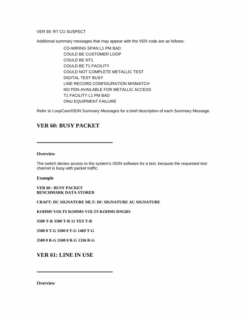
VER 59: RT CU SUSPECT
Additional summary messages that may appear with the VER code are as follows:
CO-WIRING SPAN L1 PM BAD COULD BE CUSTOMER LOOP COULD BE NT1 COULD BE T1 FACILITY COULD NOT COMPLETE METALLIC TEST DIGITAL TEST BUSY LINE RECORD CONFIGURATION MISMATCH NO PDN AVAILABLE FOR METALLIC ACCESS T1 FACILITY L1 PM BAD ONU EQUIPMENT FAILURE
Refer to LoopCare/ISDN Summary Messages for a brief description of each Summary Message.
VER 60: BUSY PACKET
Overview
The switch denies access to the system's ISDN software for a test, because the requested test channel is busy with packet traffic.
Example
VER 60 : BUSY PACKET BENCHMARK DATA STORED
CRAFT: DC SIGNATURE MLT: DC SIGNATURE AC SIGNATURE
KOHMS VOLTS KOHMS VOLTS KOHMS RNGRS
3500 T-R 3500 T-R 11 YES T-R
3500 0 T-G 3500 0 T-G 1469 T-G
3500 0 R-G 3500 0 R-G 1336 R-G
VER 61: LINE IN USE
Overview

LoopCare has determined that the line was being used at the time of testing, but no speech was detected. Further analysis showed the Line In Use signature for the switch in question. This condition can occur for all switch types (see below for the different LIU signatures).
Additional Information
In step-by-step offices, a VER 61 indicates a "called party" line in use. This condition is defined as the case where LoopCare tests the called party and a talk path is established but no speech is detected.
The following signatures define this VER Code:
SWITCH LoopCare RESISTANCE LoopCare VOLTAGE 1,2 & 3 ESS 0 to 3500 K T-R -36 to -75 Volts one side to ground 07 to 1.2 K T-G +15 to -15 Volts other side to ground 07 to 1.2 K R_G SXS > 200 K T-R 0 to 2.5 K T-G < 3V T-G > 200 K R-G < 3V R-G 1 & 5 XBAR < 10 K T-R 0 to 1 K T-G -42 to -54 Volts one side to ground 0 to 1 K R-G +10 to -10 Volts other side to ground
On a Crossbar switch an additional check is made for a 500 Hz permanent signal. If this signal is not detected, a line in use condition exists. If it is detected, permanent signal is identified and an ROH test is attempted.
See Also
VER codes related to VER 61 (LINE IN USE) are listed below:
VER 17 RESISTIVE FAULT AND DC FEMF VER 72 MDF TEST RECOMMENDED- PERM SIGNAL VER 73 LINE IN USE OR PERMANENT SIGNAL VER 74 PERMANENT SIGNAL
VER 63: CRAFT ACTION
Overview
When status of the Digital Subscriber Line (DSL) indicates that it has been taken out of service because a person is doing maintenance work on it, VER_63 is returned. The status returned by the switch can be:
D-OOS-MAIN DIS (D-channel is out of service, disabled for maintenance) B-OOS-MAIN DIS (B-channel is out of service, disabled for maintenance)

D-OOS-MANUAL REMOVE (D-channel is out of service, manually removed)
Additional Information
VER_63 was added with the implementation of LoopCare/ISDN. The first summary message that appears for this VER code is:
VER 63: CRAFT ACTION
Additional summary messages that may appear with the VER code are as follows:
DSL OUT OF SERVICE USER MANUALLY OUT OF SERVICE
Refer to LoopCare/ISDN Summary Messages for a brief description of each Summary Message.
VER 71: RECEIVER OFF HOOK (ROH)
Overview
When LoopCare sees an initial busy condition, it also see a short. LoopCare thinks that the line is being used, but no speech was detected. It then checked for a Line In Use or Permanent Signal condition, but didn't find one. Next it runs the receiver-off-hook (ROH) test and an ROH condition was detected. (This condition will exist only if the DC resistance value falls between 100 ohms and 3.4 kohms.) No further tests are performed.
Additional Information
If the displayed LoopCare DC resistance value is between 0 and 100 ohms, LoopCare recognizes the trouble as a short that may be within or outside the central office (VER 26) and recommends an MDF test to sectionalize the trouble. If the resistance value is between 100 ohms and 3.4 kohms, LoopCare may determine that the trouble stems from an ROH condition (VER 71) or requires manual confirmation of this (VER 75). If the resistance value is above 3.4 kohms, LoopCare classifies the problem as a short between the central office and the subscriber (VER 22).
Example
VER 71: BUSY- NO SPEECH
ROH
See Also
VER codes related to VER 71 (ROH) are listed below:
VER 22 SHORT

VER 6 SPEECH VER 61 LINE IN USE VER 72 MDF TEST RECOMMENDED- PERM SIGNAL VER 73 LINE IN USE OR PERM SIGNAL VER 74 PERMANENT SIGNAL VER 75 SHORT - PROBABLY ROH
VER 72: MDF TEST RECOMMENDED- PERMANENT SIGNAL
Overview
This VER code will appear on crossbar numbers that are equipped with 7AREGs. First, LoopCare decides that the line is busy, but hears no speech. Then, LoopCare detects permanent signal on the line, but cannot release the CO battery. So, it recommends an MDF test.
Additional Information
The MDF test is recommended so that the CO battery can be removed from the line. When the line is accessed and tested from an MDF trunk (with a LOOP test for example) the CO part of the line is physically removed from the circuit. This allows the test to be made on the outside part of the line without interference from the CO battery. The trouble can then be sectionalized. The following LoopCare DC SIGNATURE will identify this condition:
SWITCH LoopCare RESISTANCE LoopCare VOLTAGE 1,5 XBAR < 10 K T-R 0 to 1 K T-G -42 to -54 Volts one side to ground 0 to 1 K R-G +10 to -10 Volts other side to ground
See Also
VER codes related to VER 72 (MDF TEST RECOMMENDED- PERMANENT SIGNAL) are listed below:
VER 61 LINE IN USE VER 71 ROH VER 73 LINE IN USE OR PERMANENT SIGNAL VER 74 PERMANENT SIGNAL
VER 73: LINE IN USE OR PERMANENT SIGNAL

Overview
LoopCare decided that the line was busy, but didn't see any speech. Next it checks for permanent signal or line in use conditions. This VER Code will occur in two conditions:
1. In a step-by-step office only -- either a line in use condition exists on the line or a permanent signal is present. In the step-by-step, these two conditions cannot be distinguished. If it is permanent signal, it is caused by one of the following:
o ROH (not detectable because line is not ROH-testable)
o Resistive fault drawing in the line circuit.
2. In either an SXS or ESS switching office -- if a busy signature is detected and the T-R LoopCare DC RESISTANCE is between 0 and 3500 K ohms
3. In a 5ESS office -- with a hard short of 0.1 to 3.4 K ohms, the ROH test cannot always be run. When LoopCare detects this condition, this VER code will be set. To investigate the problem further, run an MDF test.
Additional Information
This condition rarely occurs on a line served by an ESS office but occurs more frequently on step-by-step. The signatures under which these messages will be displayed are given below:
ESS, SXS
A busy signature was detected and the LoopCare resistance is 0 to 3500 K T-R. This condition rarely occurs in an ESS office.
The following LoopCare resistances and voltages are identified:
ESS only
LoopCare RESISTANCE LoopCare VOLTAGE
0 to 3500 K T-R
.07 to 1.2 K T-R
.07 to 1.2 K R-G
-36 to -75 Volts one side to ground and +15 to -15 Volts other side to ground.
SXS only
LoopCare RESISTANCE LoopCare VOLTAGE
0 to 3500 K T-R
.07 to 1 K T-R
.07 to 1 K R-G
-30 to -75 Volts one side to ground and +22 to -22 Volts other side to ground.
To determine if the permanent signal is caused by an ROH, you could attempt to call the customer or monitor the line (with TV). If the ROH cannot be confirmed, assume that the trouble is a resistive fault.

See Also
VER codes related to VER 73 (LINE IN USE OR PERMANENT SIGNAL) are listed below:
VER 17 RESISTIVE FAULT AND DC FEMF VER 61 LINE IN USE VER 72 MDF TEST RECOMMENDED- PERMANENT SIGNAL VER 74 PERMANENT SIGNAL
VER 74: PERMANENT SIGNAL
Overview
In ESS and crossbar offices, LoopCare decides that the line is busy, but there is no speech. Next, it checks for permanent signal and finds it. The permanent signal is on the line because of a resistive fault or an ROH condition that LoopCare cannot detect because the line is not ROH testable.
Additional Information
The LoopCare DC SIGNATURES that identify a permanent signal condition are listed below:
SWITCH LoopCare RESISTANCE LoopCare VOLTAGE
1,2,& 3 ESS
.15 to 3.4 T-R
> 150 K T-G
> 150 K R-G
< 3 Volts T-G
< 3 Volts R-G
1,5 XBAR
< 10 K T-R
0 to 1 K T-G
0 to 1 K R-G
-42 to -54 Volts one side to ground +10 to -10 Volts on the other side
To determine if the permanent signal is caused by an ROH try to call the customer or monitor the line with the TV mask. If the ROH cannot be confirmed, assume that the trouble is a resistive fault.
See Also
VER codes related to VER 74 (PERMANENT SIGNAL) are listed below:
VER 17 RESISTIVE FAULT AND DC FEMF VER 61 LINE IN USE

VER 71 ROH VER 72 MDF TEST RECOMMENDED- PERMANENT SIGNAL VER 73 LINE IN USE OR PERMANENT SIGNAL
VER 75: SHORT - PROBABLY ROH
Overview
In all central offices except those with crossbar switches, LoopCare determines that a tip-to-ring short exists if the resistance value on the displayed LoopCare DC signature is below the locally settable fault threshold. (Default value for the threshold is 150 kohms.)
If the resistance value is between 100 ohms and 3.4 kohms, LoopCare will run a receiver-off-hook (ROH) test. If this test doesn't verify an ROH condition, it may not be possible for LoopCare to determine directly whether the trouble is the result of an off-hook receiver or a short. LoopCare then will display the VER 75 message, which asks that you verify the presence of an ROH condition either by monitoring the line, checking with the subscriber, or following local procedures. If an ROH condition apparently does not exist, you should then dispatch craft to locate the trouble.
Additional Information
If the displayed LoopCare DC resistance value is between 0 and 100 ohms, LoopCare recognizes the trouble as a short that may be within or outside the central office (VER 26) and recommends an MDF test to sectionalize the trouble. If the resistance value is between 100 ohms and 3.4 kohms, LoopCare may determine that the trouble stems from an ROH condition (VER 71) or requires manual confirmation of this (VER 75). If the resistance value is above 3.4 kohms, LoopCare classifies the problem as a short between the central office and the subscriber (VER 22).
See Also
VER codes related to VER 75 (SHORT - PROBABLY ROH) are listed below:
VER 22 SHORT FAULT VER 26 MDF TEST RECOMMENDED- LOW RESISTANCE VER 71 ROH
VER 80: DIAL OK
Overview

The LoopCare rotary dial test (DIAL) was run and the results indicate that the dial was working properly. This means that the dial speed was correct (8 to 11 pulses per second), and the percent break was within acceptable ranges (57 to 64 percent).
Additional Information
The LoopCare rotary dial test is only available from the TV and TEST masks. As a result this VER code will not appear on a basic or mini output report.
See Also
VER codes related to VER 80 (DIAL OK) are listed below:
VER 81 DIAL NOT OK
VER 81: DIAL NOT OK
Overview
The LoopCare rotary dial (DIAL) test has been run and a problem with the dial has been detected. The problem could be with the dial speed (correct dial speed is 8 to 11 pulses per second), or the percent break (the correct range for the break is 57 to 64%). Remember, however, that the percent break may occasionally fall within this range and the summary message will still say DIAL NOT OK. This is because the break that is reported in the test results is an average for all 10 pulses. If even one fails, LoopCare will report that the dial was not ok, but the average break may still fall within the acceptable range.
Additional Information
The LoopCare rotary dial test is only available from the TV and TEST mask. Therefore this VER code will never appear on a basic or mini output report.
See Also
VER codes related to VER 81 (DIAL NOT OK) are listed below:
VER 80 DIAL OK
VER 90: C-MESSAGE NOISE
Overview
C-message noise metallic and/or C-message noise longitudinal faults have been found on the pair. C-message noise on the pair is measured in the units of decibels reference nice (dBrnC) (decibels above reference noise, C-message weighted) and subjected to the standard C-message filtering (~300 to 3,000 Hz). C-message filtering is used because it is the normal voice

frequency range of a POTS line. Two measurements are made: longitudinal (noise to ground) and metallic, and noise balance is calculated from them.
Example
VER 90: C-MESSAGE NOISE LONGITUDINAL NOISE 93 DB
CRAFT: DC SIGNATURE MLT: DC SIGNATURE AC SIGNATURE KOHMS VOLTS KOHMS VOLTS KOHMS RNGRS 3500 T-R 3500 T-R 1583 Y T-R 3500 0 T-G 3500 0 T-G 1146 T-G 3500 0 R-G 3500 0 R-G 876 R-G
VER 91: INVALID PBX SIGNATURE
Overview
The LoopCare DC SIGNATURE was not what was expected for the type of PBX termination indicated in the line record. A list of the valid LoopCare DC SIGNATURES for PBXs is found in Appendix E - Valid DC Signatures.
Additional Information
Check the LoopCare DC SIGNATURE that is displayed against the DC signature expected for a 756 PBX. A 756 PBX should have the following LoopCare DC SIGNATURES:
756 A option S
KOHMS VOLTS 18-25 T-R > 200 < 3 T-G > 200 < 3 R-G
756 A option R
KOHMS VOLTS > 54 T-R 7-13 40-55 T-G > 200 < 3 R-G
The LoopCare DC SIGNATURE in the above example does not match a valid DC signatures. The line record may be incorrect and the condition on the line might be a fault.
See Also
VER codes related to VER 91 (INVALID PBX SIGNATURE) are listed below:

VER 92 INVALID AC SIGNATURE VER U2 UNEXPECTED PBX SIGNATURE
Also refer to Appendix C (TERM EQUIPMENT EFFECTS), and APPENDIX E (VALID DC SIGNATURES).
VER 92: INVALID AC SIGNATURE
Overview
LoopCare has found that the AC SIGNATURE was not what was expected for the type of equipment and services indicated in the line records. A list of the valid AC SIGNATURES is provided in Appendix F (VALID AC SIGNATURES).
Additional Information
Check the LoopCare AC SIGNATURE against the AC signature expected for a Key System. A Key system should have the following AC signature:
KOHMS 2-18 T-R > 25 T-G > 25 R-G
In the example above, the AC resistance T-R is not within the 2-18 Kohm range, thus causing the invalid AC signature.
If the AC signature displayed does not match the one expected, determine if the AC signature matches any of the valid ones listed in Appendix F. It could be that the line records are wrong but the termination is a recognizable one.
If the AC signature does not match any in Appendix F, then the condition might indicate trouble on the line.
See Also
VER codes related to VER 92 (INVALID AC SIGNATURE) are listed below:
VER 91 INVALID PBX SIGNATURE VER G1 POSSIBLE LONG LOOP VER U3 UNEXPECTED RINGER TERMINATION
Also refer to Appendix C (TERM EQUIPMENT EFFECTS) and Appendix F (VALID AC SIGNATURES).
VER 93: POOR BALANCE

Overview
LoopCare detects no major faults on the line except poor longitudinal balance (below the locally settable fault threshold), and poor capacitive balance (less than 95%). This condition could be caused by one of the following:
• ringer improperly connected to ground
• cable imbalance due to bridge tap
• incomplete line records (for example, if a line has a range extender (REG) and the associated line record byte is missing, the line will look unbalanced).
Important! There is no longitudinal balance test for RMUs, CMUs, and REG units; therefore this VER code refers to poor capacitance balance in the case of RMUs, CMUs, and REG units. If the RMU is used, however, as a DMU-C or DMU-R, then the longitudinal balance and soak tests will be performed.
Additional Information
On a single party service this problem most likely could be handled by dispatching someone to station.
On a two party line, the condition may be caused by one party having more phones than the other. If this is the case some of the recommendations include:
• Reassign parties
• add C.O. bridge
• add dummy ringers to the line to balance the ringers on each side.
See Also
VER codes related to VER 93 (POOR BALANCE) are listed below:
VER 96 MARGINAL BALANCE
VER 95: RESISTIVE FAULT AND OPEN
Overview
LoopCare has detected one or more DC resistances below the locally settable fault value (short or grounds). In addition, LoopCare has detected an open on the line. Because of the effect of the resistive fault on the line, LoopCare may not be able to tell if the open is in or out of the central office.

An open is simply a physical break in a telephone line. This can be the result of corrosion on the customer's line, or other causes. Sometimes, the wires are shorted together or have DC leakages to ground, as well. When these resistive faults are present, the normal measurements that LoopCare makes of distance to an open circuit can not be made reliably. In this case, LoopCare gives you a VER 95, with resistive faults between 50 Kohms and the level determined below (usually 150 Kohms).
The level at which LoopCare decides not to measure the distance is set by a local Facilities Manager in the telephone company. If the value is not set, then LoopCare will use 150 Kohms.
If the line is served by a Digital Loop Carrier System (DLCS) and is tested by a Remote Measurement Unit (RMU), then LoopCare makes its measurements from the Remote Terminal (RT) of the DLCS. Thus, since LoopCare can only measure "out" from the RT, LoopCare knows that the fault is at or beyond the RT.
Additional Information
It is likely that both troubles are related. If the values of the resistive fault are large enough to indicate that the fault is outside of the CO (approximately > 2 Kohms) you can assume that the open is also out of the CO. If clearing one problem does not lead to clearing the other, a subsequent test (post dispatch) will detect it.
See Also
VER codes related to VER 95 (RESISTIVE FAULT AND OPEN) are listed below:
VER 21 GROUND FAULT VER 22 SHORT FAULT VER 25 SHORT AND GROUND VER 41 OPEN OUT- BALANCED VER 42 OPEN OUT- CABLE VER 44 OPEN OUT- 2 PTY OR BRIDGE LIFTER VER 45 OPEN OUT- NEAR DROP
VER 96: MARGINAL BALANCE
Overview
LoopCare has detected no major faults on the line, but the longitudinal balance was marginal (less than 65 DB but greater than the locally settable fault value, which by default is 40 DB).
Additional Information
The marginal balance is generally not a severe problem. However, depending on the customer report, work load, and local policy, you can choose whether or not to dispatch someone on this trouble.
See Also

VER codes related to VER 96 (MARGINAL BALANCE) are listed below:
VER 93 POOR BALANCE
VER 97: DERIVED PR NOT TESTED-PHYSICAL PR NOT SERVED
Overview
LoopCare is requested to test a derived pair. However, the derived pair cannot be tested because the physical pair is on a line not served by LoopCare.
Additional Information
If the derived pair cannot be tested because the physical pair is not served by LoopCare, you should probably send the trouble to a bureau where the physical pair can be test.
See Also
VER codes related to VER 97 (DERIVED PR NOT TESTED-PHYSICAL PR NOT SERVED) are listed below:
VER NT TEST NOT MADE (NOT TESTED) VER NV NOT VERIFIED (NOT TESTED)
VER 98: ANALYSIS OF FULL RESULTS NEEDED
Overview
This VER code condition is a "catch-all" condition set when LoopCare does not identify or set any VER code conditions in testing. As a default, VER 98 is displayed to the user with the messages explaining that the detailed results should be examined. One condition that might commonly set this VER code is the case where the line is an uncataloged AC termination or a multiparty (4 or 8) line. In these cases LoopCare does not know what the AC signature should look like and does not attempt to classify the condition on the line. Instead it leaves the analysis up to the user.
The summary messages and the detailed results should provide the necessary information about the trouble.
Additional Information

VER 98 is set because no VER condition is detected. There will be summary messages to indicate what you should look at in the detailed test results to identify the condition on the line. This means that you should examine the DC and AC signatures and compare them against known valid signatures. Also look at other information such as balance and central office information to identify any particular pattern. Sometimes there are no test results or only incomplete test results. This situation could be due to premature termination of testing. A good suggestion in this case would be to retest the line in an attempt to get more complete results. If, however, the same thing occurs and no test results are available, follow local procedures.
VER 99: MULTIPLE FAULTS DETECTED
Overview
This VER code condition is a "catch-all" for cases where LoopCare wants to return more than one VER code. The summary messages and the detailed results will provide the necessary information about the trouble.
Additional Information
When VER 99 is set the summary messages should provide enough information to identify the problems. There is such a wide range of conditions that could cause VER 99 that it is not really practical to list the known ones here. In addition, there are conditions that we really don't know about right now. As you work with LoopCare you will find certain patterns of test results resulting in VER 99. It would be a good idea to keep track of these cases, especially if the actions required to handle them are similar.