london southend airport airspace change proposal southend airport - airspace change proposal...
TRANSCRIPT

LONDON SOUTHEND AIRPORT - AIRSPACE CHANGE PROPOSAL
CL-5113–ACP-008 Part B Annex A Final Cyrrus Limited Annex A 1 of 19
London Southend Airport
Airspace Change Proposal
Introduction of Standard Instrument Departure Procedures
to Routes in the London Terminal Control Area
Sponsor Consultation - 2016
Annex A to Part B
of the Consultation Document
Runway 23 Departures via EVNAS – LAM

LONDON SOUTHEND AIRPORT - AIRSPACE CHANGE PROPOSAL
CL-5113–ACP-008 Part B Annex A Final Cyrrus Limited Annex A 2 of 19
Contents of Annex A to Part B
1. RUNWAY 23: DEPARTURES TO THE WEST ....................................................... ANNEX A 3
2. THE LAM 1F SID PROCEDURE ........................................................................ ANNEX A 5
3. DIFFERENCES BETWEEN THE LAM1F SID AND THE PDR ..................................... ANNEX A 9
4. OTHER OPTIONS CONSIDERED ..................................................................... ANNEX A 11
5. ENVIRONMENTAL IMPACT .......................................................................... ANNEX A 13
APP A1. DIAGRAM OF THE LAM 1F SID OVERLAID ON OS TOPOGRAPHICAL MAP............ ANNEX A 15
APP A2. DIAGRAMS OF THE LAM 1F SID AND HISTORIC TRACKS OF AIRCRAFT FLYING THE PDR ANNEX A 16
APP A3. SEL CHART FOR AIRBUS A319 ...................................................................... ANNEX A 18
APP A4. DEPARTURE SWATHES FOR LAM PDR AND LAM 1F SID .................................. ANNEX A 19
LONDON SOUTHEND AIRPORT - AIRSPACE CHANGE PROPOSAL
CL-5113–ACP-008 Part B Annex A Final Cyrrus Limited Annex A 3 of 19
1. Runway 23: Departures to the west (EVNAS – LAM)
1.1. The procedure is known as the LAM 1F SID and reflects as closely as practicable the PDR from Runway 231.
1.2. EVNAS is a position within the LTMA approximately 2NM west of Hanningfield Reservoir and has previously been used to define the historic PDRs from LSA. LAM is the site (near to Stapleford Aerodrome) of a ground-based navigational facility (Lambourne VOR/DME) which defines a number of Airway alignments and traffic flows which are essential to the operation of the LTMA, in particular the traffic flow inbound to LHR from the east2.
1.3. It is emphasised at the outset that the portion of the SID from EVNAS to LAM is essentially for flight planning purposes only, in order to provide procedure design linkage to the LTMA route network. Aircraft will seldom actually follow this portion of the SID as they will, normally prior to EVNAS, have been given further climb clearance and a tactical routing towards the north-west to facilitate the most expeditious flight profiles and use of airspace. However, due to other routes in the vicinity, it has not been possible to develop a formal flight plannable route within the procedure and airspace design requirements which reflects the normal day-to-day routing of aircraft. This is explained in more detail later in this document.
1.4. This route is currently utilised (Summer 2015) by approximately 11 scheduled services per week3. It is also used by non-scheduled and positioning flights within the UK and Ireland. Forecast traffic growth is expected to lead to approximately 50 flights per week by 2021.
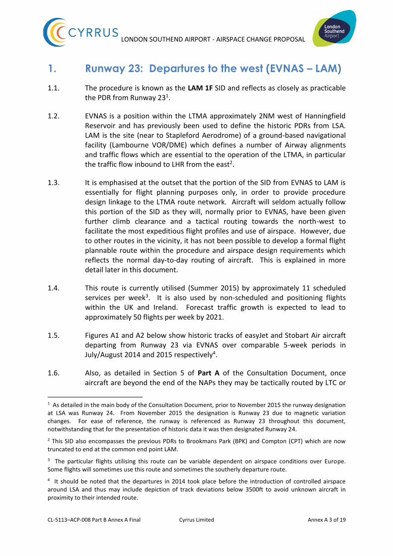
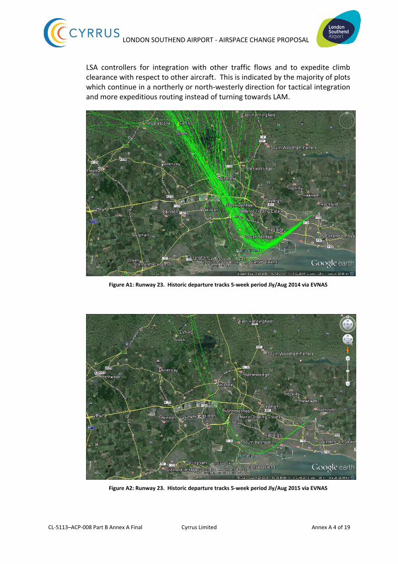
1.5. Figures A1 and A2 below show historic tracks of easyJet and Stobart Air aircraft departing from Runway 23 via EVNAS over comparable 5-week periods in July/August 2014 and 2015 respectively4.
1.6. Also, as detailed in Section 5 of Part A of the Consultation Document, once aircraft are beyond the end of the NAPs they may be tactically routed by LTC or
1 As detailed in the main body of the Consultation Document, prior to November 2015 the runway designation at LSA was Runway 24. From November 2015 the designation is Runway 23 due to magnetic variation changes. For ease of reference, the runway is referenced as Runway 23 throughout this document, notwithstanding that for the presentation of historic data it was then designated Runway 24.
2 This SID also encompasses the previous PDRs to Brookmans Park (BPK) and Compton (CPT) which are now truncated to end at the common end point LAM.
3 The particular flights utilising this route can be variable dependent on airspace conditions over Europe. Some flights will sometimes use this route and sometimes the southerly departure route.
4 It should be noted that the departures in 2014 took place before the introduction of controlled airspace around LSA and thus may include depiction of track deviations below 3500ft to avoid unknown aircraft in proximity to their intended route.
LONDON SOUTHEND AIRPORT - AIRSPACE CHANGE PROPOSAL
CL-5113–ACP-008 Part B Annex A Final Cyrrus Limited Annex A 4 of 19
LSA controllers for integration with other traffic flows and to expedite climb clearance with respect to other aircraft. This is indicated by the majority of plots which continue in a northerly or north-westerly direction for tactical integration and more expeditious routing instead of turning towards LAM.
Figure A1: Runway 23. Historic departure tracks 5-week period Jly/Aug 2014 via EVNAS
Figure A2: Runway 23. Historic departure tracks 5-week period Jly/Aug 2015 via EVNAS
LONDON SOUTHEND AIRPORT - AIRSPACE CHANGE PROPOSAL
CL-5113–ACP-008 Part B Annex A Final Cyrrus Limited Annex A 5 of 19
2. The LAM 1F SID procedure
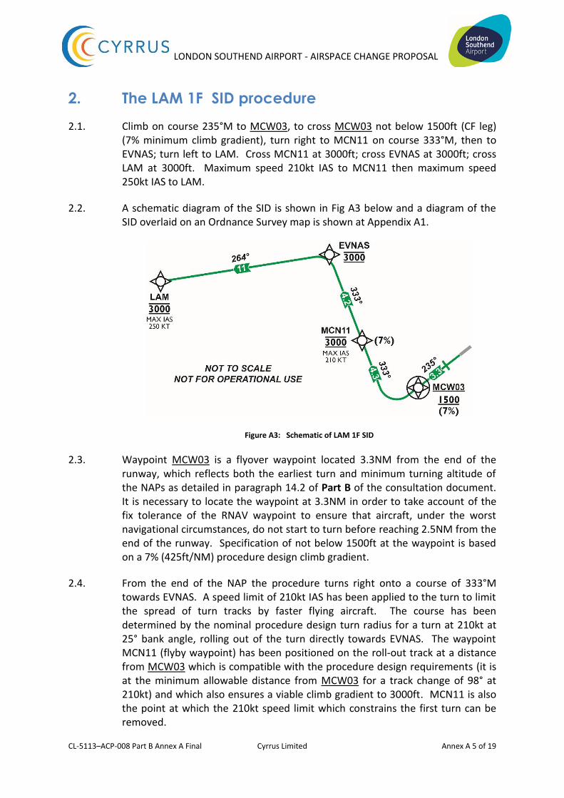
2.1. Climb on course 235°M to MCW03, to cross MCW03 not below 1500ft (CF leg) (7% minimum climb gradient), turn right to MCN11 on course 333°M, then to EVNAS; turn left to LAM. Cross MCN11 at 3000ft; cross EVNAS at 3000ft; cross LAM at 3000ft. Maximum speed 210kt IAS to MCN11 then maximum speed 250kt IAS to LAM.
2.2. A schematic diagram of the SID is shown in Fig A3 below and a diagram of the SID overlaid on an Ordnance Survey map is shown at Appendix A1.
Figure A3: Schematic of LAM 1F SID
2.3. Waypoint MCW03 is a flyover waypoint located 3.3NM from the end of the runway, which reflects both the earliest turn and minimum turning altitude of the NAPs as detailed in paragraph 14.2 of Part B of the consultation document. It is necessary to locate the waypoint at 3.3NM in order to take account of the fix tolerance of the RNAV waypoint to ensure that aircraft, under the worst navigational circumstances, do not start to turn before reaching 2.5NM from the end of the runway. Specification of not below 1500ft at the waypoint is based on a 7% (425ft/NM) procedure design climb gradient.
2.4. From the end of the NAP the procedure turns right onto a course of 333°M towards EVNAS. A speed limit of 210kt IAS has been applied to the turn to limit the spread of turn tracks by faster flying aircraft. The course has been determined by the nominal procedure design turn radius for a turn at 210kt at 25° bank angle, rolling out of the turn directly towards EVNAS. The waypoint MCN11 (flyby waypoint) has been positioned on the roll-out track at a distance from MCW03 which is compatible with the procedure design requirements (it is at the minimum allowable distance from MCW03 for a track change of 98° at 210kt) and which also ensures a viable climb gradient to 3000ft. MCN11 is also the point at which the 210kt speed limit which constrains the first turn can be removed.
LONDON SOUTHEND AIRPORT - AIRSPACE CHANGE PROPOSAL
CL-5113–ACP-008 Part B Annex A Final Cyrrus Limited Annex A 6 of 19
2.5. Vertical constraints
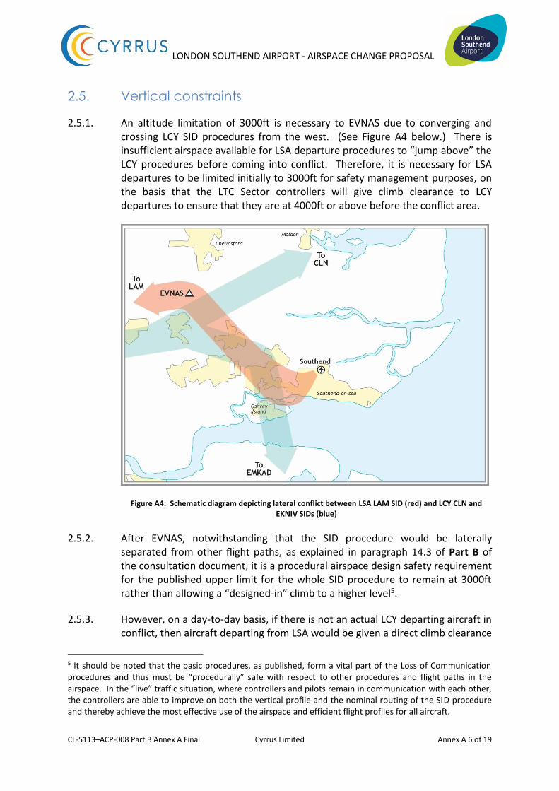
2.5.1. An altitude limitation of 3000ft is necessary to EVNAS due to converging and crossing LCY SID procedures from the west. (See Figure A4 below.) There is insufficient airspace available for LSA departure procedures to “jump above” the LCY procedures before coming into conflict. Therefore, it is necessary for LSA departures to be limited initially to 3000ft for safety management purposes, on the basis that the LTC Sector controllers will give climb clearance to LCY departures to ensure that they are at 4000ft or above before the conflict area.
Figure A4: Schematic diagram depicting lateral conflict between LSA LAM SID (red) and LCY CLN and EKNIV SIDs (blue)
2.5.2. After EVNAS, notwithstanding that the SID procedure would be laterally separated from other flight paths, as explained in paragraph 14.3 of Part B of the consultation document, it is a procedural airspace design safety requirement for the published upper limit for the whole SID procedure to remain at 3000ft rather than allowing a “designed-in” climb to a higher level5.
2.5.3. However, on a day-to-day basis, if there is not an actual LCY departing aircraft in conflict, then aircraft departing from LSA would be given a direct climb clearance
5 It should be noted that the basic procedures, as published, form a vital part of the Loss of Communication procedures and thus must be “procedurally” safe with respect to other procedures and flight paths in the airspace. In the “live” traffic situation, where controllers and pilots remain in communication with each other, the controllers are able to improve on both the vertical profile and the nominal routing of the SID procedure and thereby achieve the most effective use of the airspace and efficient flight profiles for all aircraft.

LONDON SOUTHEND AIRPORT - AIRSPACE CHANGE PROPOSAL
CL-5113–ACP-008 Part B Annex A Final Cyrrus Limited Annex A 7 of 19
to a higher level either once in contact with the LTC radar controller or by the LSA radar controller in co-ordination with the LTC controllers. Standing Agreements will be in place between LSA ATC and LTC Sectors to ensure that climb clearance above the initial limit is given to the aircraft at the earliest opportunity.
2.5.4. Empirical evidence indicates that aircraft departing from LSA would regularly be expected to be above 4000ft6 before reaching the vicinity of EVNAS, notwithstanding that this cannot, for the safety management reasons detailed above, be specified within the procedure. Figure A5 below provides a colour-coded plot of historic climb performance of departing aircraft via EVNAS over a 5-week period in July/August 2015.
Figure A5: Colour coded climb profile of departing flights Summer 2015. [Colour coding: Below 3000ft red; 3000 – 4000ft orange; 4000 – 5000ft yellow;
5000 – 7000ft light green; above 7000ft dark green]
2.5.5. It can be seen that for these flights, all aircraft had been cleared to climb and were above 3000ft before completing the first turn after departure and slowest climbing aircraft was above 4000ft before reaching Hanningfield Reservoir (i.e. abeam EVNAS).
2.6. Radar Vectoring
2.6.1. As noted in Section 5 and paragraph 9.4 of Part A of the consultation document, it is essential that controllers retain the operational flexibility to integrate
6 An A319 given unrestricted climb clearance in typical weather conditions could be expected to be at approximately 6000ft by EVNAS.
LONDON SOUTHEND AIRPORT - AIRSPACE CHANGE PROPOSAL
CL-5113–ACP-008 Part B Annex A Final Cyrrus Limited Annex A 8 of 19
aircraft flight paths with one another to achieve the most effective and efficient overall traffic flow and to get departing aircraft climbing to their cruising levels as quickly as possible. Therefore, once aircraft have completed the NAP segment of the SID procedure, controllers may use radar vectoring to achieve the most efficient and expeditious flight profiles of aircraft at the lower levels of the TMA airspace.
2.6.2. This flexibility is particularly important, and will remain so, for aircraft departing from LSA towards the EVNAS.
2.6.3. Notwithstanding that the flight plannable SID routing must be via LAM for airspace design purposes, it is invariably more efficient on a tactical basis for controllers to radar vector LSA departing aircraft away from the holding pattern at LAM (for LHR inbound aircraft) and more towards the north or north-west.
2.6.4. However, there is no fixed, or predetermined, track for such radar vectoring; the chosen flight path would be dependent on many factors such as the position of STN departing (runway 22) or arriving (runway 04) aircraft and LUT eastbound departures within the overall traffic flow. Controllers are also required to ensure that LSA departing aircraft are given prompt climb clearance so that they stay above the base levels of controlled airspace.
2.6.5. Thus departing aircraft via EVNAS are likely to be radar vectored somewhat to the east of EVNAS and are highly unlikely to fly along the EVNAS – LAM segment of the SID. Equally, they will invariably be given climb clearance above 3000ft well before reaching the vicinity of EVNAS.
LONDON SOUTHEND AIRPORT - AIRSPACE CHANGE PROPOSAL
CL-5113–ACP-008 Part B Annex A Final Cyrrus Limited Annex A 9 of 19
3. Differences between the LAM 1F SID and the PDR
3.1. Diagrams showing the proposed LAM 1F SID overlaid on the actual tracks of aircraft operating on the previous LAM/BPK/CPT PDRs are shown at Appendix A2. The widths of the swathes depicted in Appendix A2 are ±1NM from the nominal route centre-line for the outer swathe, which represents the “worst case” flight safety navigational tolerance used for procedure design, and ±0.2NM for the inner swathe, which represents what we expect to be the day-to-day navigation accuracy expected on RNAV1 routes (based on experience of other ATM applications of RNAV-1 operations elsewhere).
3.2. It should be noted that the PDRs were, historically, not designed to any formal procedure design criteria and the tracks to be flown were not specified with reference to the navigation infrastructure. It is therefore not possible to provide an exact comparison between the nominal tracks of the SID procedure (designed to PANS-OPS criteria) and the PDR. However, the SID reflects, as closely as practicable, the historic PDRs via EVNAS to LAM (including this portion of the PDRs to BPK and CPT) and the operation of aircraft on the SID will generally reflect the historic distribution of aircraft using the PDR.
3.3. Procedure design speed limits were not applied to the PDR, other than the standard international airspace speed limit of 250kt IAS outside controlled airspace. We have applied a speed limit of 210kt IAS for the SID procedure to limit the westerly extent of the initial turn by faster aircraft. In selecting an appropriate speed limit a fine balance is necessary between the preferred operating configurations and speeds of the variety of aircraft using the route and the ATM and environmental objectives. The application of the speed limit ensures that LSA departing aircraft do not fly further to the west than is necessary in the initial turn and assists in resolving the conflict between LSA departures and LCY departures as quickly as possible. The procedure initial speed limit is removed as soon as is practicable within the procedure design criteria.
3.4. It is seen from the diagrams at Appendix A2 that the route of the proposed SID procedure reflects as closely as practicable the historically demonstrated routing of aircraft following the PDR.
3.5. With respect to the upper limit of the procedures, before the introduction of controlled airspace departing aircraft via EVNAS were permitted to climb initially to 3400ft. This was to ensure that the aircraft remained outside controlled airspace until given further climb clearance by LTC, the base level of controlled airspace being 3500ft. However, where both aircraft are inside controlled airspace the vertical separation to be applied by ATC is 1000ft. Thus, with the introduction of controlled airspace at LSA in April 2015 the upper limit of the PDRs has been changed to 3000ft. To ensure that standard separation is

LONDON SOUTHEND AIRPORT - AIRSPACE CHANGE PROPOSAL
CL-5113–ACP-008 Part B Annex A Final Cyrrus Limited Annex A 10 of 19
sustained with the introduction of SIDs, the initial level incorporated in the procedure design for LSA SID procedures must be 3000ft.
LONDON SOUTHEND AIRPORT - AIRSPACE CHANGE PROPOSAL
CL-5113–ACP-008 Part B Annex A Final Cyrrus Limited Annex A 11 of 19
4. Other Options considered
4.1. Use of flyby waypoints: The use of flyby waypoints throughout the procedure design, which would be the preferred methodology for aircraft navigation systems, was considered in the outline development of the procedure design. However, the positioning of the initial waypoint (defining the start of the first turn following noise abatement) to meet both the procedure design criteria and the definition of the noise abatement procedure meant that the track “rolling out” of the turn towards EVNAS would be noticeably to the west of the track achieved by aircraft following the PDR. Conversely, using a flyover waypoint to define the start of the turn indicated that aircraft would more closely replicate the tracks flown on the PDRs. LSA therefore elected to utilise the flyover waypoint configuration rather than flyby configuration.
4.2. Direct to LAM: This option is not feasible. This track would be almost “head on” to southbound routes from STN7, LUT and Northolt (which are normally altitude restricted on the southbound leg due to higher traffic inbound to LHR) and would converge too rapidly with all departure procedures from LCY to ensure that the necessary separation standards could be achieved. Opportunity for early climb would be extremely limited and LSA departures would be subject to significant departure delay caused by the closer presence of conflicting LCY departures. Furthermore, notwithstanding that the formal SID procedure must be specified via LAM for flight plannable linkage to the LTMA route structure, the day-to-day ATM tactical requirement for efficient airspace utilisation is to route departing aircraft further to the east. Therefore a procedure design routing directly to LAM would be less representative of the ATM requirement. Therefore this option has been ruled out.
4.3. An earlier right turn: A right turn before 2.5NM from the end of the runway would offer distinct operational advantages to ATC as it would provide greater flexibility in reducing (but not eliminating) the conflict between aircraft departing from LCY and aircraft departing from LSA. It would also provide a more expeditious turn away from the LCY approach path along the Thames Estuary. However, it would result in overflight of a larger population as more people in Eastwood and Rayleigh would be more affected by departing aircraft at low altitude. Moreover, an earlier right turn would require a change to the NAPs. LSA is not seeking to change the long-standing NAPs, which are the subject of a Section 106 Agreement. Therefore, this option has been ruled out.
4.4. A later right turn: Extending the “straight ahead” element of the departure procedures to beyond the 3.3M position (i.e. 2.5NM + fix tolerance) would increase the interaction between departure procedures from LSA and those from LCY to the extent that lateral separation of aircraft could not be assured.
7 Due regard has been taken of the proposed change to the distribution of STN southbound traffic for the LAMP Phase 1a airspace arrangements.
LONDON SOUTHEND AIRPORT - AIRSPACE CHANGE PROPOSAL
CL-5113–ACP-008 Part B Annex A Final Cyrrus Limited Annex A 12 of 19
Thus LSA departing traffic would be wholly dependent on “gaps” between successive LCY departures resulting in increased ATC co-ordination, departure delays and potentially, runway congestion at LSA. Departing aircraft would be held down at lower altitudes for longer as the conflict with LCY traffic would take longer to resolve. Furthermore, any substantial westerly extension of the LSA departure track would place it in conflict with the approach path to runway 28 at LCY. Moreover, this option would require the provision of further, highly contentious controlled airspace for the containment of the SID IFPs. This option is not feasible and therefore ruled out.
4.5. More northerly route to the east of EVNAS: This possibility was considered in detail in the airspace development stage as tactical (radar directed) routing of aircraft in the pre-controlled airspace era was frequently used to expedite departing traffic and facilitate earlier climb clearances (as depicted in the track plots at Figure A1). A more easterly route would have avoided the congested uncontrolled airspace around Hanningfield Reservoir in the design of the Southend Controlled Airspace. However, complex procedural lateral and vertical conflictions would exist against STN inbound and outbound traffic and LCY inbound traffic as well as against LSA inbound traffic from the north. Extensive and detailed studies by NATS and LSA, taking due regard of the airspace configuration and route structure for LAMP Phase 1a, were unable to devise a safe, standard and flight plannable route to join the Airways System though the north-eastern part of the LTMA that was procedurally safe. Thus routing of the formal SID procedure via LAM must be retained, notwithstanding that in most circumstances departing aircraft will be tactically routed once they are under the control of LTC and climbing to higher levels.
4.6. Higher procedure altitudes: Extensive and detailed studies were carried out co-operatively by LSA and the NATS LAMP Phase 1a development team to try and establish an upper limit above 3000ft at EVNAS for the LSA departure procedure. However, conflict with LCY departure procedures crossing above and the projected climb performance of the LCY traffic precluded, on a safety management basis, the allocation of a higher level for LSA aircraft turning right after departure (see Figure A4 above). Furthermore, the safety management requirements with respect to “stepped climbs” in SID procedures and SSR Mode S depiction on LTC radar controllers data displays (as explained in paragraph 14.3 of Part B of the consultation document) has precluded the inclusion of higher levels in the published procedure.

LONDON SOUTHEND AIRPORT - AIRSPACE CHANGE PROPOSAL
CL-5113–ACP-008 Part B Annex A Final Cyrrus Limited Annex A 13 of 19
5. Environmental impact
5.1. The nominal route of the SID very closely reflects both the NAP and the nominal route of the PDR within the constraints of the procedure design criteria. Furthermore, the day-to-day ATC management of aircraft on the SID will very closely reflect the previous operation of aircraft on the PDR in that they will be radar vectored to the north-west instead of turning towards LAM. However, the improved overall airspace efficiencies afforded by the recently introduced LAMP Phase 1a airspace arrangements are expected to result in much earlier climb clearance for LSA departing aircraft on this route.
5.2. The Airport Noise Contours are not affected by the change from PDR to SID as detailed in Part A Section 7. The increase in contour size from 2014 to 2021 would occur irrespective of whether the departure procedures remain as current or are changed to SIDs.
5.3. The introduction of a speed limit for the initial turn of the SID, together with a specified track towards EVNAS, will reduce the spread of aircraft tracks around the turn and the initial routing towards EVNAS, thereby reducing the number of people affected by departing aircraft on this route.
5.4. The SEL Chart at Appendix A3 shows a slight change to the alignment of the “far out” extremity of the 80dB(A) SEL contour. This is due to the position of the first flyover waypoint which defines the NAP as a consequence of the PANS-OPS procedure design criteria.
5.5. Table A1 below shows the area and population within the 80 and 90 dB(A) SEL footprints for departures by the Airbus A319 on the current route and the proposed SID procedure.
SEL Value
Runway Route
Area (Km2) Population (thousands)
Current route
SID Current route
SID
90 dB(A)
23 LAM
2.6 2.6 4.8 4.5
80 dB(A)
12.6 12.6 36.3 37.2
Table A1: SEL Footprints LAM PDR and LAM 1F SID
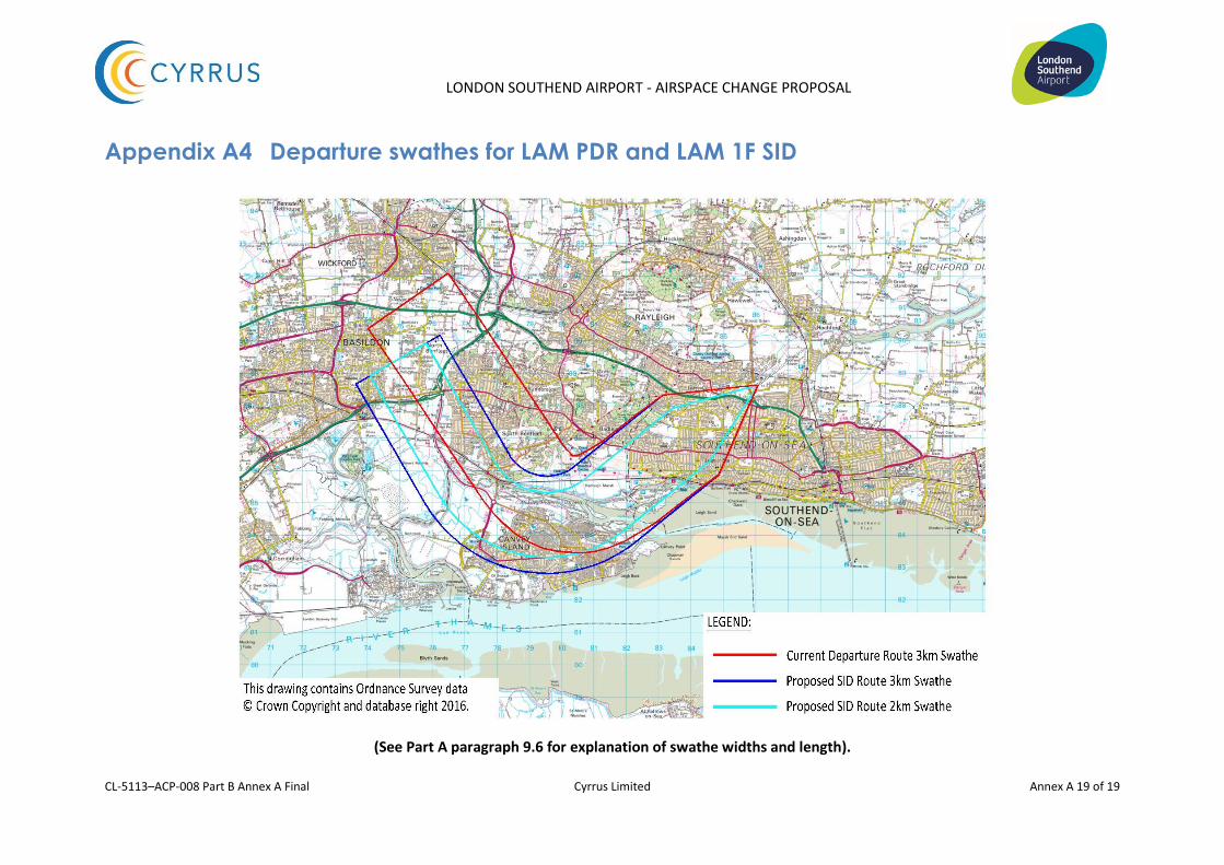
5.6. The Chart at Appendix A4 shows the departure swathes against which population counts have been made. The criteria against which the swathe widths and length have been determined are detailed in Part A Section 9.5 of the consultation document. Whilst the swathe widths reflect the general

LONDON SOUTHEND AIRPORT - AIRSPACE CHANGE PROPOSAL
CL-5113–ACP-008 Part B Annex A Final Cyrrus Limited Annex A 14 of 19
practice used at other UK airports it should be noted that we expect the day-to-day track-keeping performance for departing aircraft using the RNAV-1 SID procedures to be better than the 2km swathe width used for this analysis.
5.7. Table A2 below provides a comparative count of the number of people within the respective swathes for the historic PDR and the proposed LAM 1F SID.
Runway Route
Population (thousands)
Current Route (PDR) (nominal 3km width)
SID (nominal 2km width)
23 LAM 87.4 58.6
Table A2: Population Count for PDR and SID
5.8. The introduction of properly constructed RNAV SIDs with a navigation standard of RNAV-1 will result in improved repeatability of tracks in accordance with CAA policy and DfT guidance and this, in conjunction with the recently introduced controlled airspace around LSA and the improved airspace efficiency resulting from the recently introduced LAMP Phase 1a airspace arrangements, will enable earlier climb clearance to be given to departing aircraft above the 3000ft initial limitation of the SID procedure However, tactical radar vectoring of aircraft before reaching EVNAS will remain an operational requirement in order to achieve the most efficient flight profiles and use of airspace further away from LSA.
5.9. Therefore, it is concluded that the impact of changing the PDR to a formal SID procedure brings an overall environmental benefit to communities on the ground as well as to improved flight profiles and reduced fuel burn for aircraft operators.
LONDON SOUTHEND AIRPORT - AIRSPACE CHANGE PROPOSAL
CL-5113–ACP-008 Part B Annex A Final Cyrrus Limited Annex A 15 of 19
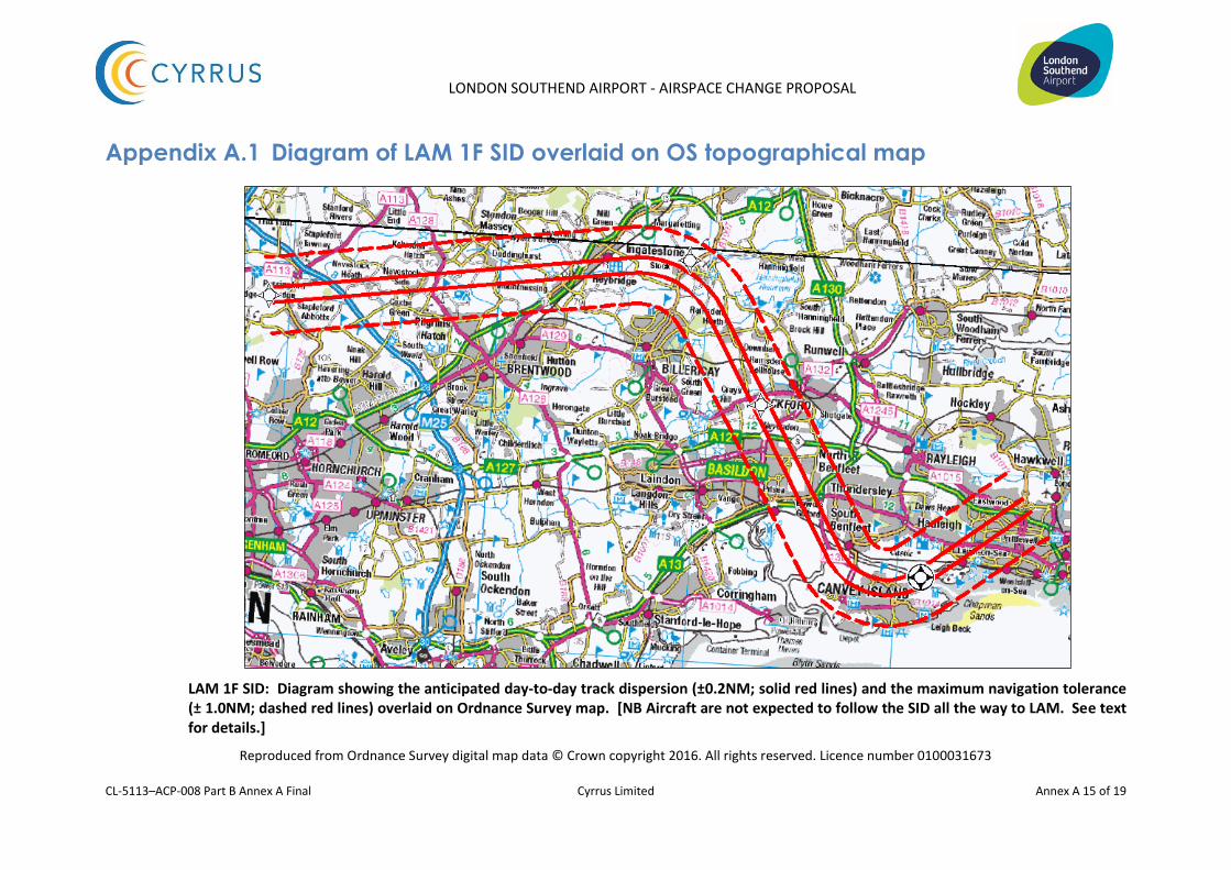
Appendix A.1 Diagram of LAM 1F SID overlaid on OS topographical map
LAM 1F SID: Diagram showing the anticipated day-to-day track dispersion (±0.2NM; solid red lines) and the maximum navigation tolerance (± 1.0NM; dashed red lines) overlaid on Ordnance Survey map. [NB Aircraft are not expected to follow the SID all the way to LAM. See text for details.]
Reproduced from Ordnance Survey digital map data © Crown copyright 2016. All rights reserved. Licence number 0100031673
LONDON SOUTHEND AIRPORT - AIRSPACE CHANGE PROPOSAL
CL-5113–ACP-008 Part B Annex A Final Cyrrus Limited Annex A 16 of 19
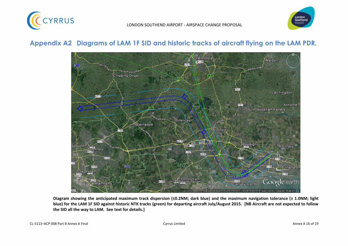
Appendix A2 Diagrams of LAM 1F SID and historic tracks of aircraft flying on the LAM PDR.
Diagram showing the anticipated maximum track dispersion (±0.2NM; dark blue) and the maximum navigation tolerance (± 1.0NM; light blue) for the LAM 1F SID against historic NTK tracks (green) for departing aircraft July/August 2015. [NB Aircraft are not expected to follow the SID all the way to LAM. See text for details.]

LONDON SOUTHEND AIRPORT - AIRSPACE CHANGE PROPOSAL
CL-5113–ACP-008 Part B Annex A Final Cyrrus Limited Annex A 17 of 19
Diagram showing the anticipated maximum track dispersion (±0.2NM; dark blue) and the maximum navigation tolerance (± 1.0NM; light blue) for the LAM 1F SID against historic NTK tracks (green) for departing aircraft July/August 2014. [NB Aircraft are not expected to follow the SID all the way to LAM. See text for details.]

LONDON SOUTHEND AIRPORT - AIRSPACE CHANGE PROPOSAL
CL-5113–ACP-008 Part B Annex A Final Cyrrus Limited Annex A 18 of 19
Appendix A3 SEL Chart for A319 aircraft.
LONDON SOUTHEND AIRPORT - AIRSPACE CHANGE PROPOSAL
CL-5113–ACP-008 Part B Annex A Final Cyrrus Limited Annex A 19 of 19
Appendix A4 Departure swathes for LAM PDR and LAM 1F SID
(See Part A paragraph 9.6 for explanation of swathe widths and length).