london midland region - wordpress.com
TRANSCRIPT


LONDON MIDLAND REGION
B R I T I S H R A I L W A Y S
MINISTRY OF TRANSPORT, Berkeley Square House,
Berkeley Square, London, W. 1.
19th March, 1952. SIR,
I have the honour to report for the information of the Minister of Transport, in accordance with the Order dated 21st September 1951, the result of my Inquiry into the derailment which occurred at approximately 11.15 a m . on that day near Weedon, about 14 miles south of Rugby, on the Western Division double-track main line in the London Midland Region, British Railways.
The 8.20 a.m. Up express passenger train from Liverpool to Euston, comprising 15 bogie coaches hauled by a Pacific type engine, was travelling at 60-65 m.p.h. on the leaving transition of a left handed curve of about 50 chains radius, when the leading bogie wheels of the engine were derailed to the right ; the cause was an engine defect. The derailment was not noticed by the enginemen at this stage and the train continued forward at speed for more than + mile on the straight without serious damage to the flat bottom track. No more wheels were derailed until the train reached the bull head rails just beyond the short Stowe Hill tunnel, when the leading bogie wheels began to smash the chairs and break up the track with the result that the whole of the train left the rails except for the last two vehicles.
The engine went down the 12 ft. embankment to the left, and fell on its left hand side: on soft ground. The wreckage of the coaches at the front of the train was severe, and I regret to state that seven passengers and'one of the dining car staff were killed outright and seven passengers died subsequently in hospital. In addition, 26 passengers, the engine driver, and nine members of the dining car staff were admitted to hospital, or 36 persons in all, of whom 15 were discharged on the same day, and 25 others sustained minor injuries or shock. The driver, who was on the left hand side of the footplate, had a fortunate escape from serious injury when he was buried in coal from the tender as the engine overturned ; the fireman clung to the right hand side of the cab and was unhurt.
The wreckage of the eight leading coaches was piled behind and alongside the overturned engine across both the tracks. It was seen by the signalman at Heyford box 950 yards ahead when he heard the noise of the final derailment, and he stopped the approaching Down "Royal Scot" express a t his outer home signal at 11.19 am., and afterwards drew it forward to the box. The block and telephone wires northward were severed, but the signalman got a message through to the Control via Blisworth, the next junction box to the south. Medical and other assistance was also summoned from all possible sources by some officers of the Metropolitan Police who had seen the wreckage from their car on the neighbouring main road. The Northamptonshire County Police were quickly on the scene and performed outstanding services in co-ordinating the work of rescue.
Local doctors were in attendance within seven minutes. They were assisted in first aid by two doctors who were travelling in the train, and medical staff and ambulances had arrived in force by 11.45 a m . Passengers from the derailed train and from the Down Royal Scot co-operated in the rescue work with the local railway staff, the Police and the Northamptonshire County Fire Brigade, with the result that all of the injured were on their way to hospital by 12.15 pm., one hour after the accident. Detachments were also sent by the Royal Army Ordnance Corps from the Weedon depot and by the Royal Army Medical Corps, and valuable assistance was given by local residents, as well as by the Salvation Army and the W.V.S., who set up mobile canteens ; it should be mentioned that a retired nurse, Miss Raynor, who is more than 70 years of age, walked two miles to the site from Weedon carrying a case of medical supplies. The success of the relief work generally was due in no small measure to the plans which have been drawn up by the Railway Executive in conjunction with the Police all over the country for dealing with emergencies of this kind.
The heavy breakdown cranes from Rugby and Willesden arrived at 1.32 p m . and 4.0 p m . respectively, and were supplemented a t 5.30 p m . by the breakdown train from Bletchley. Permanent way gangs were also required to relay 155 yards of the Up line, and to put new rails in 40 yards of the Down line. Many men of the breakdown and relaying gangs worked without a break except for snatched meals until the lines were re-opened to traffic at 5.30 pm. on 22nd September after an interruption of just over 30 hours.
The crane work was hampered by the embankment site. Rerailing of the slightly damaged vehicles at the rear of the train was straightforward, but the nine leading coaches had to be set aside clear of the tracks and removed during subsequent week ends when the line would be closed to traffic. The engine lay at such a distance from the tracks that it was impossible to lift it bodily, and two cranes had to be used to roll it upright onto a sleeper crib at the foot of the bank ; it was then drawn back to formation level on a temporary close-sleepered track and lifted on to the Up line. These awkward operations could not be completed until Sunday 28th October after the coaches had been got out of the way and piles driven into the bank to support the cranes.

The blockage of the line resulted in the cancellation of a considerable number of freight trains and a few passenger trains, but most of the passenger traffic in both directions was diverted to the alternative route through Northampton with comparatively slight delays, and road services were organised for the local traffic. The Down Royal Scot was worked back to Blisworth a t 1.45 p.m. and sent forward from there on its journey via Northampton ; it conveyed a considerable number of passengers from the derailed train who changed at Northampton into trains for London. The Weedon stationmaster, Mr. S. Yorke, who had hastened to the site on learning of the accident through the Control, took a prominent share in these arrangements and did much good work in other ways.
The weather was fine, though it was not particularly warm, and the rails were dry
1. The general characteristics of the section of the Line concerned and the gradients are shown by Figs. 1 a n d 3 on the attached Plan A. Weedon is a wayside station about 13 miles south of Rugby on the West Coast main line to London (Euston) from the North. As the surrounding country is hilly, there is considerable cut and fill, and the Up line falls towards Weedon on easy gradients for the 6+ miles from the Kilsby Tunnel summit. Up trains approach the station on a left handed curve which is followed by a right handed curve beyond the platforms and then by another left handed curve. The initial derailment occurred
1 1
rather less than a mile beyond the station on the leaving transition of this last left handed curve, which is approximately 840 yards long and is designed as a compound curve with radius varying from 48 to 53 chains. After that the line is straight for the 1,597 yards to the point where the train was finally derailed after passing 3 through the 492 yards Stowe Hill tunnel, and for a considerable distanc'e beyond.
2. Fig. 1 also shgws the types of permanent way laid in the Up line. The material on the last 710 yards of the curve in question and on the succeeding straight nearly to the tunnel consisted of flat bottom rails of very heavy section, 131 lbs. per yard. This was followed through the tunnel by a length laid with British Railways standard 109 lbs. flat bottom rails, extending to the junction with the 95 lbs. R.B.S. bull head track where the complete derailment began.
The 131 lbs. rails had been laid experimentally in 1939 with clip fastenings on rolled steel bearing plates coach screwed to the timber sleepers. of which there were 24 per 60 feet rail length. The rails were joined by four-bolt fishplates weighing 86f lbs. per pair. Owing to wear in the clip fastenings this length was "replated" in 1949 with cast iron bearing plates as used for 110 lbs. F.B. rails, and elastic spike fastenings, two inside add one outside each rail.
3. The curve was last surveyed, re-aligned and re-canted in 1941, when the monuments were adjusted in the six foot way. As shown by Fig. 4 on Plan B, they provide for a leaving transition of 270 feet, by which the cant is run down on a gradient of 11540 from the 5a ins. on the last part of the circular curve, where the radius is 48 chains ; this is the theoretical or equilibrium cant for 65 m.p.h., and represents a deficiency of l* ins. at 75 m.p.h., the maximum speed now permitted. Within this limit there is no restriction on any of the reverse curves at Weedon. With present day timings, the usual speed of Up express trains at this point is 65-70 m.p.h.
4. I examined the track in detail a few days after the accident ; it had received no attention in the meantime, and traffic was passing under speed restriction. The low rails on the curve were not much worn, but side wear on the high rails was nearing the permissible limit and the cross section given at Fig. 5 on Plan B was representative. Some rails had been changed owing to the development of cracks in the webs at the joints ; in one case a piece had actually broken out of the rail end, and owing to these failures and the side wear, the 131 lbs. track as a whole had been proposed for renewal in 1953, after 14 years life.
Y 5. Fig. 4 also shows the actual gauge and cant on the last 240 yards of the curve, as well as the actual
radii calculated from the versines of 90 feet overlapping chords, measured on the low rail. It will be seen that the gauge generally varied from slightly tight to + in. slack, although there were two points where it was S!,, in. and Ji8 in. slack. Most of the variations appeared to be due to the loose fit of the feet of the 131 lbs. rails between the shoulders of the "110 lbs." bearing plates. It did not appear, however, that the rails were moving laterally on the plates under traffic, and there were no signs of movement of the bearing
i plates on the sleepers, which were in sound condition generally, though a few of the elastic spikes were beginning to work loose and move upward. The actual radius of the circular curve as disclosed by the versine measurements varied from 35 to 60 chains, but the maximum "slew" required at any point to restore the curve to its designed radius of 48 chains was calculated to be not more than .62 in., and the alignment appeared to be very good to the eye.
6. There were no longitudinal drains in the six foot way or the cess, but a few piped cross drains had been laid towards the canal on the Up side. The stone ballast, which was laid in 1939, was ample in quantity with good shoulders, but it was more or less clogged with dirt and this had its effect on the drainage. There were the usual signs of wet formation under some of the sleepers, as shown on the plan, and measurements were taken by void meters under the load of a heavy engine to ascertain the true cross levels.

These are shown by the "live cant" dotted line in Fig. 4 ; it will be noted that the regularity was well maintained on the circular curve, but it was not so good on the transition where the formation is inclined to be wet in the shallow cutting. In particular, there was a variation from '/,. in. low 72 feet before the point of derailment to in. high 40 feet before it ; at the point of derailment itself the cant was correct at l + ins. Over this length the "top" of the high rail was well nigh perfect, but there were noticeable variations in the Level of the low rail, and the low rail joint "A" appeared to be standing high. One effect of these variations was to steepen the cant gradient locally to li240 and 11320 from the designed run-off of 11540 on the transition curve.
The running on the curve was last tested by a Hallade instrument on 11th April 1951, about five months before the accident. The speed of the train was approximately 70 m.p.h., and the graphical record did not indicate any serious faults in alignment or cross level.
1 7. The engine was No. 46207, "Princess Arthur of Connaught". I t was built at Crewe in 1935 and was stationed at Edge Hill (Liverpool) shed. As shown by the outline diagram, Fig. 7 on Plan C, it was of the four-cylinder 4-6-2 express passenger type, classed 8P, and it was driven from the left hand side. The wupled
C wheels are 6 ft. 6 ins. diameter and the tractive effort at 85 % of the boiler pressure (250 lbs. per square in.) is 40,3M) Ibs. With a load of 22 tons 10 cwts. on each of the coupled axles, the weight in working order with six wheeled tender is 159 tons 3 cwts. The wheelbase of the engine is 37 ft. 9 ins., with a rigid wupled wheelbase of, 15 ft. 3 ins. As is usual in engines of long wheelbase, the middle coupled wheels have thin flanges, but the bogie and rear pony wheels have flanges '1, in. thicker than standard to improve steadiness of running at high speed. The coupled wheels have underhung and the rear carrying wheels overhung laminated springs. The leading bogie has a single inverted laminated spring at each side, the load on which is divided between the leading and trailing axle boxes by twin compensating beams. The designed weighr distribution is shown by the diagram.
8. The weight of the engine at the front end is transmitted to the bogie centre casting by heavy cast steel brackets bolted to the main frames at each side. A hemispherical projection on the underside of each bracket is seated in a cast iron cup with a plane under-surface, which slides, in accordance with the lateral displacement of the bogie, on an oil-lubricated gunmetal alloy pad on the bogie centre casting. As shown by Fig. 8, there is a socket at each side of the centre casting which bears directly on a spigot formed integrally with the buckle of the laminated spring, and the weight on the spring is transferred to the axle boxes by the twin compensating beams which are linked to it. The comparatively light bar frames of the bogie, of which the long horn stays form the lower members, thus carry no weight and serve only to locate the axles longitudinally and laterally. Nor is any weight carried by the central bogie pivot. Side control is by coil springs acting with an initial centring force of 4 tons, rising to 5 tons at the maximum displacement to one side of 2'1, ins.
9. The rear carrying axle is mounted in a pony truck with a trailing arm of 6 ft. 10 ins. radius. As with the leading bogie, the weight is transferred to the pony frame by two ball and cup assemblies, but some additional damping is given by self-lubricating ferrobestos pads on the plane sliding surfaces. Side control is also by coil springs, initially at 1.44 tons, rising to 2.96 tons a t the maximum displacement to one side of 4& ins. The control springs of the bogie and of the rear pony truck are so disposed that lateral wear is automatically taken up, and no uncontrolled side play can develop, apart from that due to wear of axle box surfaces and wheel bosses.
1
10. At the time of the derailment, engine No. 46207 had run 980,537 miles since it was put into service in 1935, and 139,395 since the last general repair in May 1949. It had run 81,405 miles since the tyres had last been turned to restore their profile at a "Heavy Intermediate" repair in May 1950, and 39,985 miles since all the axle boxes were refitted at a "Casual" repair in March 1951. On 19th June 1951, the engine was stopped for piston and valve examination and at the same time it was lifted for renewal of the rear truck bearing pads. The weight distribution was adjusted before it went into traffic again on 28th June -see also Paragraph 28 below. On 23rd July the spring of the right hand middle coupled wheel was found broken and was changed.
11. At a routine examination a few days before the accident, it was found that the left leading bogie wheel flange was wearing sharp, and the two bogie axles (together with the axle boxes) were changed over, front to rear and vice versa, when the engine was stopped at Edge Hill shed for the periodical "X" examination on the 19th and 20th September. The train in question was the first which the engine bad worked since the bogie axles were changed round, and subsequent examination after stripping in Crewe workshops disclosed that the leading bogie axle boxes were too tight in the horn guides. As will be seen later, this was the cause of the derailment.

12. The 15 bogie vehicles were screw coupled throughout, with British Standard gangways, and all were equipped with long stroke sbock absorbing buffers of former London Midland and Scottish Railway design. AU had steel underframes and bodies framed in hard wood with sheet steel panelling. They were marshalled as follows from front to rear :-
Year Weight Description Built T. Cwt.
1. Corridor 3rd Brake-5609. . . . 1933 30 0 2. Corridor 1st Brake-5070 . . . . . 1950 -30 0 3. Corridor 1st-1064 . . . . . . 1937 31 0 4. Corridor 1st-1125 . . . . . . 1950 30 0 5. Corridor 1st-1123 .. . . . . 1950 30 0 6. 1st Vestibule Dining Car-7568 . . 1939 35 0 7. Kitchen Car-30102.. . . . . 1938 35 0 8. Vestibule 3rd-9480.. . . . . 1938 29 0 9. Vestibule 3rd-9446 . .. . . . . 1938 29 0
10. Corridor 3rd-1650 . . . . . . 1934 31 0 I I . Corridor 3rd-2057 . . . . . . 1938 32 0 12. Corridor 3rd-13183 , . . . . 1950 32 0 13. Corridor 3rd-1770 ,. . . . . 1934 32 0 14. Corridor 3rd-1644 . . . . . . 1934 31 0 15. Corridor 3rd Brake-26864. . . . 1950 30 0
- 467 0 -
All the vehicles were vacuum braked, and had direct admission valves. The brake power of the train as a whole, with the steam brake on the coupled wheels of the engine and on the tender, was approximately 73% of the total weight of 626 tons. The total length was 329 yards.
13. The "Point of Derailment" shown in Fig. 4 on Plan B is the commencement of the flange mark on the surface of the high rail. This mark was a perfectly distinct trace of dark oil crossing the rail surface in a length of 37 ft. as shown by Fig. 6. There was no indentation of the rail surface whatever, and the general character of the mark suggested that the wheel was very lightly loaded at the critical moment. Nor does it appear that there was any great lateral thrust ; there was practically no scoring of the running edge of the rail before the flange began to climb, and after it had reached the rail surface it ran nearly parallel with the edge for more than 16 ft. before i t finally crossed over and dropped to the outside.
14. For the next few feet, the outside edge of the high rail had been scored by the back of the flange, and there were signs that an outside spike had been struck about 10 ft. beyond the end of the mark on the rail surface. After that, the derailed pair of wheels had continued to run displaced about 7-10 ins. to the right of the track alignment. The right hand wheel did not drop sufficiently for the flange to break the cast iron bearing plates or even to mark them heavily, but it continued to strike and damage the outside spikes without affecting their hold to any material extent. The sleepers were indented in the four foot way fairly continuously by the flange of the left hand wheel, and a considerable number of the inside spikes on the left hand rail were flattened by its tread.
15. These effects were noticed all along the straight up to and through the tunnel, and it was clear that only one pair of wheels had been derailed so far. The damage to the sleepers and fittings over this length ,
was trivial, but the track as a whole was thrown out of alignment by the passage of the engine and the train. The distortion was scarcely noticeable for the first 265 yards beyond the initial flange mark, but thenceforward for about 450 yards it alternated fairly regularly to the left and right, varying in amplitude from very slight to a maximum of 7 ins. ; the distance between successive left-right-left waves was fairly consistent a t 6C70 ft. There was practically no disturbance of the alignment through the tunnel, nor on the 224 yards of flat bottom track beyond it, on which the derailed wheels had begun to take a rather more sinuous course before they reached the bull head rails and began to smash the chairs. The effects of the derailment up to this point, including the track distortion, are indicated by Fig. l on Plan A.
16. The results of the final derailmeh, which occurred while the train was still travelling at about 60 m.p.h. are shown by Fig. 2 on Plan A. From the commencement of the bull head track, the rails were in place in the broken chairs for approximately 122 yards to the point where it appeared that the engine was completely derailed by the widening of the gauge, and began to break up the track before it was diverted down the 12 ft. embankment to the left. Thenceforward, the track of the Up Line was completely swept away for approximately 72 yards by the irregular movement of the bogies of the derailed coaches at the front of the train. The engine and tender came to rest on their left hand sides, and the front end of the engine was half buried in the soft clay field a t the foot of the bank, about 97 yards beyond the point where it was first completely derailed ; except for some dstortion of the bogie frame and a broken footstep, it was practically undamaged.

The leading third brake remained coupled to the tender. It was on its left hand side half way down the hank, with the 2nd coach, a corridor first, which had become detached, almost upside down behind and outside it in the field. The bodies of these two coaches were wrecked by the 6th, a first class diner, which was thrown across and on top of them. The 3rd and 4th coaches, also corridor firsts, were converted to a barely recognisable mass of wreckage across both the tracks and on the bank, but the 5th cbach, another corridor first, seems to have passed clear of the wreckage ahead of it, and it came to rest on the hank alongside and above the engine without very serious structural damage, though the rear end was crushed.
As mentioned above, the 6th coach was thrown on its right hand side across the 1st and 2nd ; it was not so seriously damaged as some of the others, hut the kitchen car, marshalled 7th, was demolished as it was thrust sideways and overturned on to the remains of the 3rd and 4th. The 8th coach, a vestibule third, came to rest upright diagonally across the tracks to the right with its front end panels torn out. The 9th coach, which remained coupled to the 8th, went partly down the hank and was leaning over a t about 45" but it and the remaining six vehicles were practically in line, with the last two still on the rails. The front end panels of the 9th coach were crushed against the twisted underframe of the 7th, hut there was no. serious damage to the others in reas of it.
It seemed, therefore, that the first two vehicles had followed the engine down the hank, and that the next six had assumed a'"star" formation as they ran on to the remains of the track which had been broken up by the derailed engine. The shock of their sudden deceleration from high speed was mainly
i absorbed by the destruction of the 3rd, 4th and 7th vehicles, the bodies, underframes and bogies of which were piled in a central heap of debris across the tracks and on the left band face of the bank. In addition to destruction of the bodies, therk was severe distortion of the underframes, and the heavy steel underframe
F members of the 4th coach were twisted through 180".
17. The following is a summary of approximate distances with reference to the commencement of the tlange mark on the high rail of the transition curve :-
. . . . Rugby Station . . . . . . 14 miles North
. . . . Weedon Station . . . . . . 1 ,, ,. Commencement of left hand curve . . . . 810 yards ,, Commencement of flat bottom track . . . . 680 ,, F,
Commencement of leaving transition. . . . 58 ,, ,p
Commencement of flange mark on high rail. . - First spike struck on outside of high rail . . 16 yards South End of leaving transition . . . . . . 32 ,, ,. Commencement of track distortion . . . . 265 ,, ,,
. . . End of track distortion. . . . . 715 $B ,, . . . Stowe Hill Tunnel, North end. . . 759 ,, ,B
. . ,. S , ,, South e n d . . . . 1,251 ,, ,, . . . . Junction with bullhead track . . 1,475 ,, .,
. . . . Commencement of final derailment 1,597 ,, ,, Front of engine after derailment . . . . 1,694 ,, ,, Heyford Signal Box . . . . . . . . 2,640 ,, ,, Blisworth Station . . . . . . . . 6 miles South
EVIDENCE OF TRAINMEN 18. The train left Liverpool (Lime Street) at 8.23 am., 3 niinutes late. Owing to signal checks it lost time
in running the 35 miles to the stop a t Crewe, and it left there at 10.28 a.m., 10 minutes late. There were further signal checks between Crewe and Rugby where the train was not booked to stop, and it ran through Rugby station a t 10.58 a.m., 16 minutes late, according to the guard's journal and the signal box bookings. The actual average speed for the 76 miles from Crewe to Rugby, start to pass, was 50.7 m.p.h. compared with the booked average speed of 54.3 m.p.h.
As has been mentioned, the final derailment was heard and seen by the signalman at Heyford box, and he recorded the time as 11.14 a.m., 16 minutes after the recorded time a t Rugby No. 7 box. From consideration of these times in relation to the hooking a t intermediate boxes, it seemed reasonable to
k assume that approximately 17 minutes were occupied in running the 15t miles from Rugby No. 7 box to the point of the final derailment, representing an average speed of approximately 54 m.p.h., which corresponds fairly closely with the booked average speed of this train from Rugby to Blisworth. In order to maintain this average, a maximum of about 65 m.p.h. is normally required through Weedon, and Driver Tomlin's estimate that he was travelling at about that speed on the Weedon curves was probably not far out ; it received some confirmation from Stationmaster Yorke, who saw the train pass through the station at, he said, about the usual speed. Tomlin said that he was running down the gradient with the regulator just open and the gear a t 15% cut off and, as be did not alter the controls on the slight rise to Stowe Hill tunnel, the speed may have come down to about 60 m.p.h. at the moment when the train was finally derailed.
19. Tomlin, who is stationed a t Camden Shed, is 52 years of age and has been a driver for 13 years ; he has long experience of this route and had been driving express trains between Euston Liverpool and Manchester for six months, often with engines of this class. In spite of his severe shock, he was able to give
at my Inquiry, 6 days after the accident. He stated that he had booked on duty at Edge HiU Shed a t 6.35 a.m. on the morning of the accident after lodging at Liverpool for the night. He had found that engine No. 46207 had been oiled and generally prepared for him by another pair of men, hut he went round the engine to make sure that the lubricator corks were all in place, and also gave some oil to the lubricators of the bogie side bearer slides. After coaling and watering the engine, he left the shed at 7.35 a.m. to work the 8.20 a.m. train.
5

He described the journey as uneventful, apart from the signal delays, up to the moment of the final derdhent , and said that the engine was steaming and pulling well. He had no fault to find with the riding either of the engine or the tender at any part of the journey, and he mentioned specially that the riding was very comfortable a t about 65 m.p.h. right through the Weedon curves. He noticed no unusual noise or lurching of any kind as the train continued along the straight up to and through the tunnel. Soon after the engine had emerged from the tunnel, he began to feel that it was "shaking" at the front end, and he remarked to the fireman that something seemed to he wrong with the leading bogie. He shut the regulator and applied the brake fully, but the engine was derailed almoit immediately afterwards, and he said that all was over in a matter of seconds from his first impression that something was wrong. Driver Tomlin was told of the track distortion which had been found at several points on the straight between the end of the curve and the tunnel, hut he remained unshaken in his statement that he had felt no unusual movement of any kind until the very last moment.
20. The fireman was A. S. Wallis of Camden Shed. He was Driver Tomlin's regular mate, and he evidently had a detailed knowledge of the road. He generally confirmed Tomlin's account and said that he had no difficulty in maintaining a full head of steam throughout the journey. He considered that the engine was riding very well, though there was a certain amount of rolling on the Weedon curves, as he would have expected at a speed of 60-65 m.p.h. ; he added, however, that the track there had been improved a good deal during the past year. He went on to say that the engine steadied down as usual as it ran on to the straight, and he was quite sure that he noticed no abnormal noise or oscillation until he heard Tomlin say that there was something wrong with the leading bogie, just after the engine had passed under the bridge South ofthe tunnel. He then saw sparks and dust flying from the front end, a few seconds before the engine was completely derailed.
So far as he could recollect, he was standing up a t the time and he held on the right hand side of the cab as the engine went down the hank and overturned to the left. He escaped with a few bruises
1 and had no difficulty in climbing out. He then went forward to Heyford box to warn the signalman ; according to the latter, Wallis arrived at the box in a very shocked condition a few minutes before the Down Royal Scot was drawn forward to the box at 11.50 a m .
21. The Guard, P. J. Burns, who was travelling in the brake compartment of the rearmost coach, said that the train was running at its normal speed through Weedon, and that he felt no unusual oscillation until he was thrown to the floor by a severe lurch a second or two before the coach came to rest. He went forward and on seeing Fireman Wallis running ahead he returned to the rear and protected the obstruction. Others who said that they had noticed no unqsual movement before the tunnel were Travelling Ticket Collector B. Madeley, who was starting forward from the rear coach to check tickets, and Driver W. Robertson, who was sitting in the brake compartment at the front of the leading coach ; Robertson had been learning the road from the footplate between Liverpool and Crewe.
22. On the other hand, several persons in the train referred to' rough riding or lurching in varying degrees before entering the tunnel, and all were agreed that it was followed by smooth running through the tunnel itself. Goods Guard R. W. Wehh, who was acting as Assistant Guard from Crewe to Bletchley, was in the brake compartment of the 2nd coach. He said that the riding was "very rough with a rattling noise and side to side movement" just before entering the tunnel, and that he would have reported it when he got out at Bletchley ; he did not think it was bad enough to stop the train specially for report, still less to make an emergency brake application. Assistant Cook B. J. Sorrell and Kitchen Porter H. Lever were together in the kitchen car, marshalled 7th in the train. Both men spoke of violent lateral oscillation before entering the tunnel which broke some crockery and threw some pots off the stove. They had remarkable escapes from serious injury when the kitchen car was demolished during the course of the final derailment. Mrs. D. Purcell, a travelling carriage cleaner, was with Guard Burns in the rear brake compartment at the time. She felt "a bit of wobbling" but she was not alarmed and thought it was "just the speed; she made some remark about it to Burns, but he did not reply. Violent lurching just before the tunnel was also mentioned in letters which I received from two passengers, one in the 3rd coach and the other in the fifth.
23. Written statements were furnished by the crew of the preceding train. This was the 6.32 a m . express from Llandudno to Euston, which passed through Weedon at speed at approximately 10.46 a m . Neither the driver, fireman nor guard felt any rough riding or lurching on the curves and the driver said that the road seemed to be in good condition, and that it had not deteriorated in any way since he had been over it the week before.
EVIDENCE REGARDING THE TRACK
24. Mr. B. E. B. Walker, District Engineer, Northampton, had last inspected this length of 131 ihs. Bat bottom track hhout six months before the accident. On account of the failure of the rail ends and the side wear, he had given instructions that it should be submitted for renewal in 1953. He considered that the variations of gauge were of little moment as they were not caused by weakness of the fastenings, and that they would not have led to unsteadiness of running on the curve where the flanges were normally pressed against the outer rail. Mr. Walker, and tbe Chief Permanent Way Inspector, Mr. C. E. A. Hall, thought that the alignment of the circular curve and the transition could hardly be criticised, but that the variations of cross level on the transition were such as to require attention by the ganger, though not as a matter of immediate urgency ; they felt sure, however, that the variations were not sufficient in themselves io account for the derailment, and Mr. Hall expressed the opinion that their effect would hardly he felt on the footplate. Referring to the drainage, Mr. Walker said that it was his intention to lay a drain in the six foot way through this cutting, hut that there were other places where drainage improvements were more urgent.

25. Permanent Way Inspector E. Hughes had been in charge of this district since 4th June, and was responsible for 16) miles of the main line from Roade Junction to Kilsby South. He was on his holiday at the time of the accident, and Permanent Way Inspector F. E. Harlow was acting for him. Mr. Hughes considered that the Up line at the site of the derailment was "fairly good". He explained that this qualified approval was due to the clogged and dirty ballast which required riddling, hut he was well satisfied with the maintenance of alignment, gauge and cross level, which he had inspected carefully with a gauge ahout six weeks before the accident ; he had also made a more cursory inspection 10 days before it. He spoke highly of the ganger in charge of the length, H. Stone. Mr. Harlow had not heen over this section of line until the day of the derailment. Shortly after it occurred he examined the Up line in rear of the initial flange mark ; he thought the alignment was good, but he noticed "one or two little spots" where attention was required to the levels.
26. Ganger Stone had been in charge for five years of the length gang of seven men, including himself, which was responsible for the 2% miles of double track from Weedon Station to Stowe Hill tunnel, hoth inclusive. The gang had been at full strength for some time before the derailment, hut Stone said there was always plenty of work to do, especially in the cutting near the site of tbe initial derailment where the formation was inclined to be wet ; he added that the low rail particularly of hoth tracks required fairly frequent attention to maintain its proper level under load, though the alignment gave little trouble, as he would have expected with the lateral stiffness of the heavy flat bottom rails. He had had very little trouble with the gauge since the rails were "replated" and refastened with elastic spikes in 1949.
On 12th September he had repacked about 7 or 8 rail lengths of the Up line on the transition curve, in the course of ordinary repair work to remedy low joints and some hanging sleepers. He had first "trimmed" the high rail and then had adjusted the low rail to the correct cant according to the monuments by shovel packing with chippings. In accordance with usual practice, he had left the ioints a little high to allow for their settlement under traffic, and he thought that the joint A-see Paragraph6and Fig. 4-which was found to he standing high on the low rail side, might not have gone down quite as much as he had expected. He said that this joint and a few others near it were apt to be troublesome, particularly after wet weather. He had not, however, heard of any complaints from enginemen about the running on this curve, and it was confirmed that no such reports had been received in the District Engineer's Office.
Stone and his gang were working on the track at the south end of Weedon Station when the train passed. He thought it was travelling at about the usual speed of Up express trains through weedon, perhaps 65 m.p.h.
EVIDENCE REGARDING THE ENGINE 27. After a good deal of excavation, it was possibleio examine the tyres of all the wheels of the engine
and the tender as they lay on their sides. The only wheels which bore markings to correspond with the continuous damage to the elastic spikes on the right hand sides of the rails, as described above, were the leading wheels of the bogie. On the right hand wheel there was a,network of light indentations all round the circumference towards the back of the flange, and the left hand wheel was similarly marked towards the edge of the tread, as would be expected if the wheels had been running over the spikes with a comparatively light load on them ; i n addition to these continuous light markings, there were deeper bruises, spaced at irregular intervals, on the flange of the right hand wheel and at the edge of the tread of the left hand wheel, which may have been caused by violent contact with the chairs as the wheels ran on to the bull head track. The coupled wheels had a few irregular bruises which had evidently been caused by the final derailment, and the rear pony and tender wheels were practically unmarked. It was thus established at an early stage that the leading wheels of the engine bogie had become derailed to the outside of the transition curve where the first mark was observed. It was also clear from the character of the damage to the track that no other wheels were derailed until the engine reached the bull head track beyond the tunnel.
28. Further examination of the engine a s i t lay could only be superficial. So far as could he seen, it was not damaged structurally except for considerable distortion of the bogie framing-see Fig. 9 on Plan C- and all the bearing springs and their attachments appeared to be intact. After the engine had heen re-railed on 28th October, it was worked to Crewe with a spare bogie and was weighed on arrival at the works with the original bogie in position ; the following table compares the record of this weighing with the designed distribution :- As weighed at Crewe on
Designed 6.1 1 .5 1 after derailment LH & RH LH RH
T. C. T. C. T. C . Leading Bogie . . . . . . 5 5 5 1 4 15 Trailing Bogie . . . . . . 5 5 5 1 4 15 Leading Coupled . . . . . . 11 5 10 10 10 7 Driving Coupled . . . . . . 11 5 11 6* 11 6 Trailing Coupled . . . . . . 11 5 12+ 12+ Rear Truck . . . . . . . . 8 0 9 6 7 l l+ - Weight on each side . . . . 52 5 53 44 50 14t
Total Weight . . . . 104 10 103 19 -- It will be noted that the weights on the right hand side of the bogie were lighter than standard,
but owing to the damage and the general disturbance which the engine had received, they cannot he regarded as representative of the conditions before the derailment. The weights had been adjusted as nearly as ~ossible to the standard distribution on 28th June, and there is no reason to suppose that this adjustment had been lost to any material extent at the time of the derailment nearly three months later.
7

29. After the engine had been weighed, a11 the running gear was stripped in the shops and the engine was lifted off its wheels. The absence of structural damage, apart from the distorted bogie frame, was conlirmed and all the laminated hearing springs were found in good condition with no broken plates ; they were subsequently tested and there was no material variation from standard in the relation of deflection to load. With the exception of the flange of the left trailing bogie wheel, which was wearing sharp and bad been changed from front to rear on 19th September,--see Paragraph 11-all the tyres and flanges, including those of the leading bogie wheels which were first derailed, had good profiles. There was no excessive side play between the axles knd the boxes and between the boxes and the horns, and wear at the bogie central pivot was slight. The two side control coil springs of the bogie were intact and properly fitted ; they also were subjected to a deflection-load test with satisfactory results.
30. The engine axle boxes were of solid bronze, with white metal linings in the journal bearings and on the flat surfaces working against the wheel bosses and the steel horn guides. All the journals and their hearings were in excellent condition with no signs of overheating. The coupled and rear carrying boxes were a good working fit in the horn gaps and had evidently been rising and falling freely under the action of the springs.
31. It was found, however, that both the leading axle boxes of the bogie were much too tight in the fore and aft direction, and there were unusually bright patches of considerable area on all of the four white metalled faces, which were clear evidence of excessive friction. The two trailing axle boxes of the bogie were a very slack fit, with more than 3:,, in . fore and aft play on the right hand side.
32. Measurements across the white metalled faces of the bogie axle boxes and between the horn gaps were taken with external and internal micrometers respectively, the latter with the long hornstays tightly bolted up. These measurements, which were taken at nine different points on the surfaces in each case, are tabulated in the Appendix and their averaged values are summarised below in diagrammatic form. The horn "rectangles" were true and had evidently not been affected by the frame distortion :-
LEADING TRAIL1 N G
I Difference 75 thousandths 1 I ('/64 ") I
A x l e b o x
Right Fit (thousandths) 17 Tight
Horn Gap
Left
Horn Gap
Fit (thousondths) 13 Tight
Axlebox
I i Difference 50 thousandths I l- ( 3 ~ 4 ' ) I
I appmx. I
33. It will be observed that there was an interference of 17 thousandths of an inch between the axle box and the guide of the right hand leading wheel which was derailed initially on the transition curve, and that the interference on the opposite side was 13 thousandths ; expansion of the boxes under the ordinary

running warmth might have increased the tightness by 3 or 4 thousandths. When the bogie frame was inverted with the hornstays removed, it was possible to "enter" each of the leading axle hoxes into its horn gap, but neither would fall into place under its own weight, and several blows with a heavy lead hammer were necessary to drive it down so that the hornstay could be bolted on. With the hornstays bolted in position both the axle boxes were tightly locked.
34. The right hand and left hand trailing'axle boxes were as much as S/s2 in. and l/,, in. slack respectively, and the difference between the dimensions of the two axle boxes on the right hand side was nearly 5/6, in. The ample clearances which existed between all four hoxes and their guides before the axles were changed over are shown diagonally on the diagram. The standard clearance in new work or at shop refits is 10 to 17 thousandths, and the nominal dimensions of the horn gaps and of the axle boxes when new is 9.75 ins. The enlargement to the figures shown in the diagram above was due to wear during the life of the bogie, as corrected at successive refits by renewal of the axle box face linings and grinding of the horn faces to restore their truth.
35. It has been the practice for a long time on the London Midland and Scottish Railway, and latterly in the London Midland Region, to change engine bogie wheels from front to back at the sheds (and in some cases from right to left) in order to even out tyre wear, and so keep engines in traffic for as long as possible between visits to the shops for tyre turning. A reminder on the subject was sent to the Divisional Motive Power Superintendents in July 1949.
36. When bogie axles are changed in this way, the bogie frame is first held up to the main frames by chains, or bolts and yokes, and packing pieces are placed above the axle boxes of the coupled wheels to prevent the whole engine settling down when the bogie axles are removed. The engine is then placed with the leading bogie wheels on the hydraulic drop tahle, which is then lowered carrying with it the axle complete with its boxes. After the engine has been drawn back, the table is raised again to rail level and the bogie axle is run forward clear. The engine is then moved forward again to place the trailing bogie axle over the tahle and the process is repeated.
The two axles are then changed over by a crane and the table is again used to raise them, one by one, into their places in the horns of the bogie frame. Before this is done it is the practice for the fitter to make sure by using inside and outside callipers that the axle boxes will have sufficient clearance to work freely in their "new" horns ; comparison of the axle box dimensions, front and rear, by outside callipers serves as a good indication whether e~ther is likely to be too tight in its new position. It is, of course, aU important to avoid any risk of binding, but otherwise no great refinement of fit is necessary with bogie axle boxes which do not have to withstand any piston thrust.
37. On 13th September it was reported by one of the examining fitters at Edge Hill Motive Power Depot that the flange of the left leading hogie wheel was beginning to wear sharp, and the Foreman Fitter, Mr. W. H. Backhouse, endorsed the repair card that the bogie axles should be changed over when the engine was next stopped for " X examination and boiler wash out. This was due on 19th September, and Fitter H. Bennett was given the task of stripping the bogie for the change soon after the engine had arrived at Edge Hill after working the 4.30 pm. express train from Euston on that day. He removed the front guard irons, the cylinder cock pipes and the two long hogie horn stays, and after that he was put on other work. It will be seen later that Bennett also replaced these components after the axles had been changed over by Fitter W. Taylor on the wheel drop pit.
38. Taylor, who is 47 years of age, had joined the service as an apprentice a t Edge Hill shed. He was appointed Fitter Grade I in 1939, and had been employed on wheel dropping work since 1946 ; according to his own statement, he was thoroughly experienced in the changing over of locomotive bogie axles, though he had not done so before on an engine of this particular class. He was first interviewed a few days after the accident when it was already clear that the derailment had been initiated by the leading bogie wheels. Although the engine !pd not yet been stripped and examined, the possibility that the leading axle boxes might have been binding in the horns was one of the 6rst things that came to mind, and Taylor was closely questioned on this point.
At that time, he was sure that the original "back" boxes had not been too tight in their new position in the front horns, and he said that they had gone up nicely when the drop table was raised ; he thought that their fore and aft clearance might have been l!,, in., and that the clearance of the original front hoxes in their new position in the back horns had probably been 'i,, in. or in. He was sure that none of the four boxes was tight, and he realised that tightness was "one of the main things" to look out for. He had found "many a time" when changing bogie axles that a box was too big to go up into the horns, in which case, he said, it was usual to leave the boxes in their original horns and change over the axles only ; this would require refitting of the journal bearings, and Taylor said that if he had any difficulty in the matter he would consult the supervisor.
39. Taylor was interviewed again after the engine had been examined at Crewe, and the measurements which are recorded in paragraph 32 above were explained to him in detail. He was unable to account for the tightness which was found in the leading boxes, and when he was asked to try and think what had gone wrong, he replied, "I cannot make it out. I am very particular about a tight box, more so than anything. I have always been told that and my father before me. He was a charge-hand in the shops, and he always told me that".
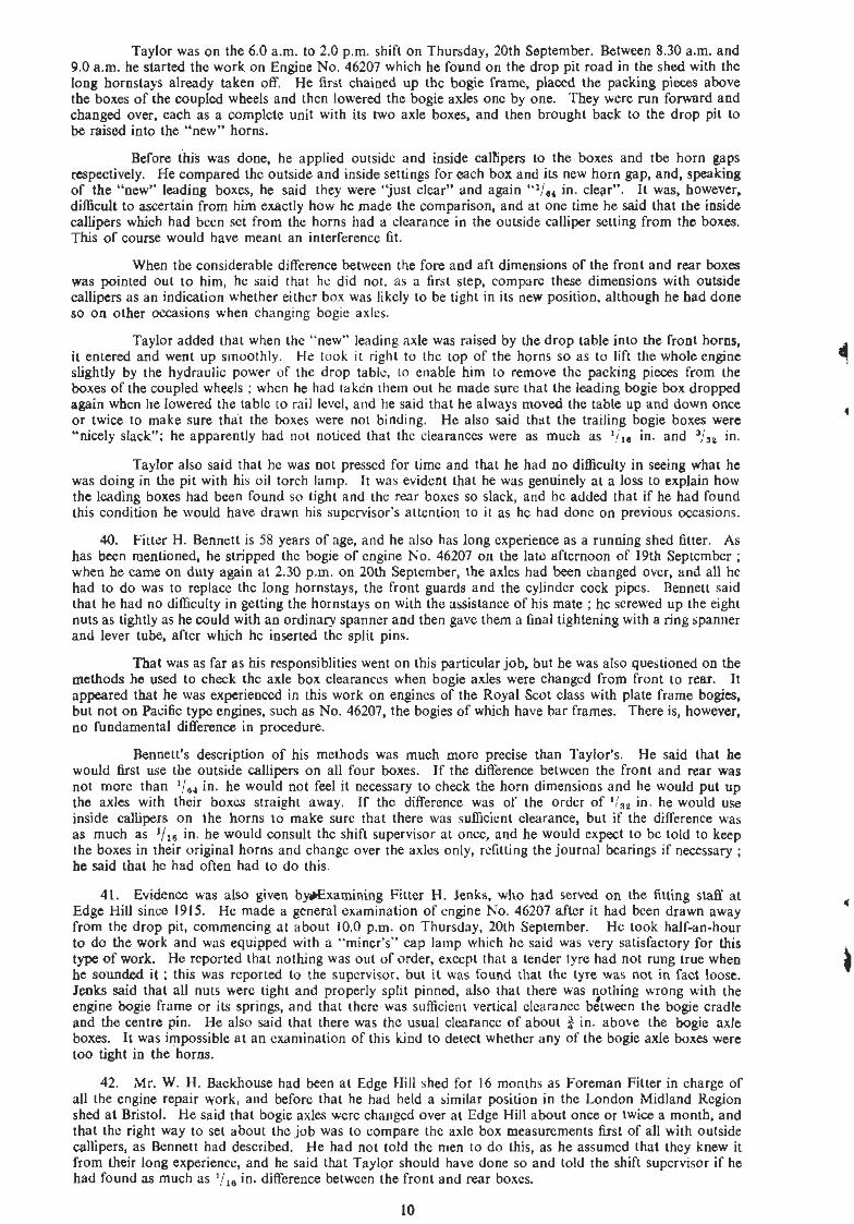
Taylor was on the 6.0 a m . to 2.0 p m . shift on Thursday, 20th September. Between 8.30 a m . and 9.0 a m . he started the work on Engine No. 46207 which he found on the drop pit road in the shed with the long hornstays already taken off. He first chained up the bogie frame, placed the packing pieces above the boxes of the coupled wheels and then lowered the hogie axles one by one. They were run forward and changed over, each as a complete unit with its two axle boxes, and then brought hack to the drop pit to be raised into the "new" horns.
Before ihis was done, he applied outside and inside caltipers to the boxes and the horn gaps respectively. He compared the outside and inside settings for each box and its new horn gap, and, speaking of the "new" leading hoxes, he said they were "just clear" and again "'/,, in. clear". It was, however, difficult to ascertain from h i exactly how he made the comparison, and a t one time he said that the inside callipers which had heen set from the horns had a clearance in the outside calliper setting from the hoxes. This of course would have meant an interference fit.
When the considerable difference hetween the fore and aft dimensions of the front and rear boxes was pointed out to him, he said that he did not. as a first step, compare these dimensions with outside callipers as an indication whether either box was likely to be tight in its new position, although he had done so on other occasions when changing bogie axles.
Taylor added that when the "new" leading axle was raised by the drop tahle into the front horns, it entered and went up smoothly. He took it right to the top of the horns so as to lift the whole engine slightly by the hydraulic power of the drop table, to enable him to remove the packing pieces from the boxes of the coupled wheels ; when he had taken them out he made sure that the leading bogie box dropped again when he lowered the tahle to rail level, and he said that he always moved the table up and down once or twice to make sure that the boxes were not binding. He also said that the trailing bogie boxes were "nicely slack"; he apparently had not noticed that the clearances were as much as in. and 3/,, in.
Taylor also said that he was not pressed for time and that he had no difficulty in seeing what he was doing in the pit with his oil torch lamp. It was evident that he was genuinely a t a loss to explain how the leading hoxes had been found so tight and the rear boxes so slack, and he added that if he had found this condition he would have drawn his supervisor's attention to it as he had done on previous occasions.
40. Fitter H. Bennett is 58 years of age, and he also has Iong experience as a running shed fitter. As has been mentioned, he stripped the bogie of engine No. 46207 on the late afternoon of 19th September ; when he came on duty again at 2.30 p m . on 20th September, the axles had been changed over, and all he had to do was to replace the long hornstays, the front guards and the cylinder cock pipes. Bennett said that he had no difficulty in getting the hornstays on with the assistance of his mate ; he screwed up the eight nuts as tightly as he could with an ordinary spanner and then gave them a final tightening with a ring spanner and lever tube, after which he inserted the split pins.
That was as far as his responsiblities went on this particular job, but he was also questioned on the methods he used to check the axle box clearances when hogie axles were changed from front to rear. It appeared that he was experienced in this work on engines of the Royal Scot class with plate frame bogies, hut not on Pacific type engines, such as No. 46207, the bogies of which have bar frames. There is, however. no fundamental difference in procedure.
Bennett's description of his methods was much more precise than Taylor's. He said that he would first use the outside callipers on all four boxes. If the difference hetween the front and rear was not more than l;,, in. he would not feel it necessary to check the horn dimensions and he would put up the axles with their hoxes straight away. If the difference was of the order of 'l,, in. he would use inside callipers on the horns to make sure that there was sufficient clearance, but if the difference was as much as l/,, in. he would consult the shift supervisor at once, and he would expect to he told to keep the hoxes in their original horns and change over the axles only, refitting the journal hearings if necessary ; he said that he had often had to do this.
41. Evidence was also given by9Examining Fitter H. Jenks, who had served on the fitting staff a t Edge Hill since 1915. He made a general examination of engine No. 46207 after it had been drawn away from the drop pit, commencing at about 10.0 p.m. on Thursday, 20th September. He took half-an-hour to do the work and was equipped with a "miner's" cap lamp which he said was very satisfactory for this type of work. He reported that nothing was out of order, except that a tender tyre had not rung true when he sounded it ; this was reported to the supervisor, but i t was found that the tyre was not in fact loose. Jenks said that all nuts were tight and properly split pinned, also that there was 5othing wrong with the engine bogie frame or its springs, and that there was sufficient vertical clearance hetween the hogie cradle and the centre pin. He also said that there was the usual clearance of ahout $ in. above the bogie axle boxes. It was impossible at an examination of this kind to detect whether any of the bogie axle boxes were too tight in the horns.
42. Mr. W. H. Backhouse had heen at Edge Hill shed for 16 months as Foreman Fitter in charge of all the engine repair work, and before that he had held a similar position in the London Midland Region shed at Bristol. He said that bogie axles were changed over at Edge W ahout once or twice a month, and that the right way to set ahout the job was to compare the axle box measurements h s t of all with outside callipers, as Bennett had described. He had not told the men to do this, as he assumed that they knew it from their long experience, and he said that Taylor should have done so and told the shift supervisor if he had found as much as l!,, in. difference hetween the front and rear boxes.
10

Mr. Backhouse said that if there was ':,, in. difference, the larger box should be machined or filed down, but when he was told that neither Bennett nor Taylor had said anything about removing metal from the axle box faces, he said that it was more usual for the boxes to be kept in their original horns in such circumstances and to be refitted to the "new" journals ; in that event, the engine would have to go for a trial run for "breaking in again". He could not suggest how Taylor had come to make the mistake, except that he might have put his caUipers across the boxes and the horns "out of line" ; he did not think, however, that a man of Taylor's experience would have done so.
When Mr. Backhouse was asked whether it was usual to leave such important work to a fitter without supervision, especially as the free fit of an axle box in its horns was essential to the safe running of the engine, he replied that if there was any difficulty, the fitter would call the attention of the shift supervisor, or himself. If things were going right, the fitters would not be interfered with ; there were 50 fitters at the shed, and he could not get round to see all their work. He also said that as a general rule the hornstays should be in place when the horn gap measurements were taken. He thought that this should apply to bogie horns as well as to the horns of coupled wheels, hut he could not say why the practice was not being followed.
t Mr. Backhouse said that Taylor and Bennett were both good workmen, though the former was
inclined to be erratic and might become flustered if things were not going right ; he had noticed this particularly on breakdown work.
43. There is no doubt whatever that the derailment of the leading wheels of the engine bogie was brought about by the lack of freedom of the axle boxes in the horns, and the way in which it developed into a major disaster has already been described.
44. The initial derailment took place on what was probably a length of the strongest track material in the country and, except for the clogged and dirty ballast which had affected the drainage, its general maintenance was good. The alignment on the circular curve and on the transition Left little to be desired, and the inequalities in the cross level were such as might have been expected with a certain degree of wetness in the formation, in spite of the continuous attention whch had evidently been given to its adjustment by Ganger Stone and his men.
I consider that, on the whole, the condition of the track was very fairly summarised in the evidence which was given by the District Engineer, Mr. Walker, the Chief Permanent Way Inspector, Mr. Hall, and by Permanent Way Inspectors Hughes and Harlow, and I am satisfied that the hest had been done under the local conditions which were not exceptional. I also agree with Mr. Walker's and Mr. Harlow's opinions that the variations in cross level which were present on the transition were not such as to give rise to any serious disturbance a t speed of a well designed engine in roadworthy condition. No undue rolling was felt at any point on the Weedon curves by the enginemen of the train concerned, nor by any one of the crew of the preceding express train.
45. Nor can there be any suggestion that the Pacific type engines of the former London and Midland Scottish Railway are, by the design of their wheel base and vertical and lateral springing, unduly sensitive to inequalities in the track. They have been employed regularly on the fastest express trains since their introduction 17 years ago with no suspicion of this kind and, indeed, have a particularly good reputation for steadiness of running.
L
46. The long length of the flange mark, and its parallel coursC for more than 16 feet may be regarded as proof that there was no abnormal side thrust by the flange of the right hand leading bogie wheel as it v became derailed. The bogie was thus performing its normal function of guiding the engine steadily as it left the curve, and in these circumstances the likelihood of derailment would be remote unless the leading
i wheels were relieved in some way of much or their proper load. The faint chara'cter of the mark on the rail surface suggested from the very first that this had occurred, although the hearing springs were subsequently found in order and there was no reason to believe that their adjustment was not correct or nearly so at the time of the derailment.
47. As this was the first trip which the engine had made since the bogie axles had been changed over, special attention was directed to the fit of the axle boxes in their horns. The conditions which were found on examination have been set out in detail in paragraphs 31-34, and it was clear that the freedom of the leading wheels to rise and fall under the action of the springs, and so retain their load as they followed the ordinary inequalities of the track, had been severely restricted by the tight fit of their axle boxes, which would have been accentuated by their expansion under the ordinary warmth of running. While it is probable that the inequalities of cross level on the transition curve provided the ultimate occasion for relief of load on the right hand leading bogie wheel as its axle box was locked or partially locked in the horns, it would be wrong to suggest that the condition of the track was responsible for the derailment of an engine with a defect of this order. Indeed the risk of derailment had been present continuously since the train had left Liverpool and no one can say how nearly it had been avoided a t other points during the journey.

48. Fitter W. Taylor mismanaged the task of changing over the two axles, which should have been well within the capacity of a skilled man of his long experience. His mistake would no doubt have been avoided if he had first of all ascertained the considerable difference between the fore and aft dimensions of the front and rear boxes, as he stated he had done on previous similar occasions ; be also seems to have appreciated that he should consult the supervisor if he had found that any of the boxes would have been unduly tight, or indeed much too slack, in their new positions. He had plenty of time for the work and it is di5cult to understand wby be did neither of these things, as he seemed to be a conscientious type of man and his record hitherto has been good ; moreover, he understood fully that over-tightness of an axle box on its horns was the one thing to he avoided above all otlrers.
It was obvious, however, that Taylor was not a clear thinker and there may have been some significance in his own statement-paragraph 39-that the inside calliper settings from the horns bad a clearance in the outside calliper settings from the boxes. He may thus have fallen into the simple error of interpreting the difference the wrong way round, and what he thought was a clearance of about l/,, inch was in fact an interference fit of the same order. He had no difficulty in pushing up the over large boxes into the front horns by means of the drop table, and they came down again under the weight of the axle when the table was lowered, but this may well be explained by lack of rigidity of the horn block assemblies when their lower ends were unsupported by the long bornstays which are integral members of the bar framing. Nor does it appear that measurements of the horn gaps without the stays in position can be very reliable with this type of frame, but i n the absence of definite instructions that they should be taken with the stays bolted up, 1 do not think that a man in Taylor's position can be blamed for not doing so, especially as his experience of changing axles was confined to engines with plate frame bogies where these considerations do not apply, at any rate to the same extent.
49. Although Fitter Taylor was at fault, I cannot feel that there had been sufficiently direct supervision and control of an operation which had such an important bearing on the safety of running, and I find it difficult to accept Mr. Backhouse's contention that he was unable to get round and give some personal attention to the work of axle changing when i t was done at the most two or three times a month at his shed. It appeared, however, that it had been accepted for a long time throughout the Region that the question of axle box clearances in such circumstances should be left to the discretion of the workman himself with no standard procedure laid down for his guidance, subject only to consultation with the supervisor if be found himself in difficulty.
50. Neither of the enginemen were aware that there was something amiss with the bogie until the derailed wheels began to smash the chairs of the bull head track a few seconds before the final derailment. This is understandable, as past experience has shown that the derailment of a single pair of wheels, especially towards the front of a large engine, is not necessarily heard or felt in the cab, and in this case the wheels were meeting with httle obstruction as they ran, more or less suspended, over the flat bottom track.
I have no doubt that the distortion of the track for some 450 yards on the bank north of the tunnel was initiated by lateral osciuation of the engine as it ran forward aft& much of the guiding effect of the bogie had been lost, and the fact that the distortion did not continue further was probably due to the higher resistance of the ballast in the tunnel and cutting. It i's difficult to say to what extent this oscillation was felt on the footplate above the ordinary movement of an engine at speed, hut in any event I am satisfied that the statements of the enginemen that they had no recollection of any unusual disturbance until the last moment, were made in all good faith.
C
On the other hand, rough riding and lurching were noticed by Guard Webb in the 2nd coach before the train entered the tunnel, also by passengers in the 3rd and 5th coaches and by the staff in the kitchen car marshalled 7th and, in view of their experience, I cannot accept that nothing of the kind was felt by Guard Burns in the last coach, which was not derailed, especially as the travelling carriage cleaner, Mrs. Purcell, spoke to him about it at the time. ,
Although a brake application directly the lurching was felt might have at least reduced the final consequences, I do not consider that any one of the train crew should be criticised for failing to take such immediate action, as it is Likely that they were reassured almost at once by the resumption of smooth running through the tunnel, whatever may have been their first reactions. The most that could have been expected in these circumstances would have been a decision to stop the train at the next box to ask that the track should be examined before a following train was allowed through the section.
51. The transposition of bogie axles had been carried out for many years in the London Midland Region without failure, but the fact that this engine went into traffic in unsafe condition has drawn attention to the need for better regulation of the work, which has to be done in the running sheds, under conditions which are d i h e n t from those in the main workshops with all their facilities for the close control of standards of fit.

This has now been appreciated. As soon as the tight fit was discovered, the Divisional Motive Power Superintendents in the London Midland Region were informed of all the circumstances, and orders wcre issued that no locomotive axles should be changed round without their personal authority, pending further review of policy and procedure. The changing of bogie axles in this way to even out tyre wear has hitherto been confined to the London Midland Region, and it is now being considered by the Railway Executive whether, as a matter of engine repair policy, th;s operation should be standardised as a general practice for British Railways or discontinued altogether as not worth while. I do not see any inherent objection on safety grounds to a practice which may be economical and avoid premature withdrawal of engines from traffic for tyre turning, provided always that adequate precautions are taken to ensure that the work is properly done. ,
52. While running shed filters are generally skilled and experienced men, they are none the less liable i n varying degree to human failure, and the circumstances of this accident have shown that it is not always sutlicient to leave standards of clearance and methods of procedure in work of this importance to their discretion and Lo place the onus on them to consult the supervisor if they think it necessary. If, therefore, it is decided to continue and extend the practice of axle changing in this way, I consider that the standards and methods to be adopted should be fully and precisely laid down, and that the final responsibility for compliance with them generally, and for ensuring that the axle boxes are correctly fitted in the horns, should rest with a senior member of the supervisory staff.
5 3 . It has been recognised that the measurement of the horn gaps should be taken with the hornstays bolted up in position, but I cannot feel that the use of inside and outside callipers can be realty satisfactory for checking the axle box clearances, especially under the conditions in the older Motive Power Depots where :he lighting is not of the best. Callipers of the large size necessary for this work are comparatively heavy and clumsy, and it is not easy to judge by eye small differences of the order of l!,, in. or '/,, in. between "internal" and "external" settings, especially when the internal setting has to be the larger of the two. Nor is it practicable under the conditions to transfer the actual settings to a steel rule and read off the difference in this way. 1 think, thzrefore, that some means should be provided so that the actual difference in dimensions between the horn gap and the axle box can be readily determined in units of measurement. Internal and external micrometers of simplified design are under consideration for this purpose, but whatever method is decided, the effective supervision of repair work must be relied on in the long run t o ensure that engines are in safe condition for traffic before they leave the shed.
54. A feature of the accident was the lack of serious damage to nearly 1,500 yards of flat bottom track material by the derailed pair of bogie wheels, and complete derailment was postponed until they began to smash the chairs of the bull head rails. In addition, therefore, to its advantages over hull head track of increased lateral and vertical strength, it is clear that Aat bottom track of this design, with shallow base plates and elastic spike fastenings, is less vulnerable to damage by derailed wheels.
I have the honour to be,
Sir,
Your obedient Servant,
G. R. S. WILSON, Lieutenant-Colonel.
The Secretary, Ministry of Transport.

APPENDIX
THE RAILWAY EXECUTIVE (LONDON MIDLAND REGION)
Mechanical and Electrical Engineer's Department,
Works Manager's Office,
CREWE.
9th November, 1951
DOIExp.
ENGINE NO. 46207. DIMENSIONS OF BOGIE HORNS AND BOXES.
Left Leading Right Leading
0 C I I C 0 10.021 10.026 10.033 10.000 10.003 10.003 10.024 10.023 10.024 10.006 l0.004 10.003 10.017 10.019 10.019 9.998 9.998 10.000
Average 10.023 Average 10.002 .
Left Trailing Right Trailing
0 C I I C 0 9.987 9.988 9.983 9.928 9.925 9.926 9.968 9.968 9.965 9.926 9.929 9.930 9.966 9.967 9.968 9.923 9.925 9.930
Average 9.973 Average.9.927
BOGIE HORNS WITH TIE BARS UP
Left Leading Right Leading
0 C I I C 0 10.015 10.015 10.013 9.971 9.977 9.981 10.009 10.007 10.008 9.985 9.985 9.g9 10.006 10.008 10.012 9.993 9.992 9.996
Average 10.010 Average 9.985
Left Trailing Right Trailing
0 C I I C 0 10.062 10.053 10.051 10.031 10.032 10.048 10.043 10.042 10.042 10.031 10.026 10.026 10.037 10.035 10.035 10.035 10.030 10.027
Average 10.044 Average 10.032


FIG.7 ENGINE N0.46207 (CLASS 8 P )
2 5 0 Ibs. per s q . in.
/ Empty { Engine 9 4 -7- 2 Weight Tender 76 - l6 - 0
Weights in Working Order 21- 0 2 2 - 10 22- 10 22- 10 1 6 - 0 18- 12 17- 16 18- 5
FRONT
FRAME BENT
FRAME BENT
REAR
I PLAN C /
F IG. 9 DISTORTED BOG1 E FRAME
N O T T O S C A L E
L E A D I N G T R A I L I N G
SECTION T H R O U G H OF BOGIE OUTSIDE VIEW WITH WHEEL REMOVED VlEW FROM L E A D I N G END VIEW THROUGH OF WHEEL
FIG. 8 GENERAL DESIGN OF LEADING BOGIE SCALE: 1 % I N C H E S T O 1 FOOT