logicore ip floating-point operator v6 - xilinx · introduction the xilinx ... mentor graphics...
TRANSCRIPT

LogiCORE IP Floating-Point Operator v6.2Product Guide
PG060 December 18, 2012
Floating-Point Operator v6.2 www.xilinx.com 2PG060 December 18, 2012
Table of Contents
SECTION I: SUMMARY
IP Facts
Chapter 1: OverviewUnsupported Features. . . . . . . . . . . . . . . . . . . . . . . . . . . . . . . . . . . . . . . . . . . . . . . . . . . . . . . . . . . . . . 6Licensing and Ordering Information . . . . . . . . . . . . . . . . . . . . . . . . . . . . . . . . . . . . . . . . . . . . . . . . . . . 6
Chapter 2: Product SpecificationStandards . . . . . . . . . . . . . . . . . . . . . . . . . . . . . . . . . . . . . . . . . . . . . . . . . . . . . . . . . . . . . . . . . . . . . . . . 7Performance. . . . . . . . . . . . . . . . . . . . . . . . . . . . . . . . . . . . . . . . . . . . . . . . . . . . . . . . . . . . . . . . . . . . . . 9Resource Utilization. . . . . . . . . . . . . . . . . . . . . . . . . . . . . . . . . . . . . . . . . . . . . . . . . . . . . . . . . . . . . . . 10Port Descriptions . . . . . . . . . . . . . . . . . . . . . . . . . . . . . . . . . . . . . . . . . . . . . . . . . . . . . . . . . . . . . . . . . 22
Chapter 3: Designing with the CoreGeneral Design Guidelines . . . . . . . . . . . . . . . . . . . . . . . . . . . . . . . . . . . . . . . . . . . . . . . . . . . . . . . . . 28Accumulator Design Guidelines . . . . . . . . . . . . . . . . . . . . . . . . . . . . . . . . . . . . . . . . . . . . . . . . . . . . . 31Clocking. . . . . . . . . . . . . . . . . . . . . . . . . . . . . . . . . . . . . . . . . . . . . . . . . . . . . . . . . . . . . . . . . . . . . . . . . 34Resets . . . . . . . . . . . . . . . . . . . . . . . . . . . . . . . . . . . . . . . . . . . . . . . . . . . . . . . . . . . . . . . . . . . . . . . . . . 34Protocol Description . . . . . . . . . . . . . . . . . . . . . . . . . . . . . . . . . . . . . . . . . . . . . . . . . . . . . . . . . . . . . . 34
Chapter 4: C Model ReferenceFeatures . . . . . . . . . . . . . . . . . . . . . . . . . . . . . . . . . . . . . . . . . . . . . . . . . . . . . . . . . . . . . . . . . . . . . . . . 42Overview . . . . . . . . . . . . . . . . . . . . . . . . . . . . . . . . . . . . . . . . . . . . . . . . . . . . . . . . . . . . . . . . . . . . . . . 42Unpacking and Model Contents . . . . . . . . . . . . . . . . . . . . . . . . . . . . . . . . . . . . . . . . . . . . . . . . . . . . . 43Installation . . . . . . . . . . . . . . . . . . . . . . . . . . . . . . . . . . . . . . . . . . . . . . . . . . . . . . . . . . . . . . . . . . . . . . 44C Model Interface. . . . . . . . . . . . . . . . . . . . . . . . . . . . . . . . . . . . . . . . . . . . . . . . . . . . . . . . . . . . . . . . . 44Compiling . . . . . . . . . . . . . . . . . . . . . . . . . . . . . . . . . . . . . . . . . . . . . . . . . . . . . . . . . . . . . . . . . . . . . . . 64Linking. . . . . . . . . . . . . . . . . . . . . . . . . . . . . . . . . . . . . . . . . . . . . . . . . . . . . . . . . . . . . . . . . . . . . . . . . . 64Dependent Libraries . . . . . . . . . . . . . . . . . . . . . . . . . . . . . . . . . . . . . . . . . . . . . . . . . . . . . . . . . . . . . . 65Example . . . . . . . . . . . . . . . . . . . . . . . . . . . . . . . . . . . . . . . . . . . . . . . . . . . . . . . . . . . . . . . . . . . . . . . . 66

Floating-Point Operator v6.2 www.xilinx.com 3PG060 December 18, 2012
SECTION II: VIVADO DESIGN SUITE
Chapter 5: Customizing and Generating the CoreGUI . . . . . . . . . . . . . . . . . . . . . . . . . . . . . . . . . . . . . . . . . . . . . . . . . . . . . . . . . . . . . . . . . . . . . . . . . . . . 70Using the Floating-Point Operator IP Core. . . . . . . . . . . . . . . . . . . . . . . . . . . . . . . . . . . . . . . . . . . . . 76Parameter Values in the XCI File. . . . . . . . . . . . . . . . . . . . . . . . . . . . . . . . . . . . . . . . . . . . . . . . . . . . . 77Output Generation. . . . . . . . . . . . . . . . . . . . . . . . . . . . . . . . . . . . . . . . . . . . . . . . . . . . . . . . . . . . . . . . 79
Chapter 6: Detailed Example DesignDemonstration Test Bench . . . . . . . . . . . . . . . . . . . . . . . . . . . . . . . . . . . . . . . . . . . . . . . . . . . . . . . . . 80
Chapter 7: Constraining the Core
SECTION III: APPENDICES
Appendix A: MigratingParameter Changes in the XCO/XCI File . . . . . . . . . . . . . . . . . . . . . . . . . . . . . . . . . . . . . . . . . . . . . . . 84Port Changes . . . . . . . . . . . . . . . . . . . . . . . . . . . . . . . . . . . . . . . . . . . . . . . . . . . . . . . . . . . . . . . . . . . . 85Functionality Changes . . . . . . . . . . . . . . . . . . . . . . . . . . . . . . . . . . . . . . . . . . . . . . . . . . . . . . . . . . . . . 87Special Considerations when Migrating to AXI . . . . . . . . . . . . . . . . . . . . . . . . . . . . . . . . . . . . . . . . . 87
Appendix B: DebuggingFinding Help on Xilinx.com . . . . . . . . . . . . . . . . . . . . . . . . . . . . . . . . . . . . . . . . . . . . . . . . . . . . . . . . . 88Debug Tools . . . . . . . . . . . . . . . . . . . . . . . . . . . . . . . . . . . . . . . . . . . . . . . . . . . . . . . . . . . . . . . . . . . . . 90Simulation Debug. . . . . . . . . . . . . . . . . . . . . . . . . . . . . . . . . . . . . . . . . . . . . . . . . . . . . . . . . . . . . . . . . 90Interface Debug . . . . . . . . . . . . . . . . . . . . . . . . . . . . . . . . . . . . . . . . . . . . . . . . . . . . . . . . . . . . . . . . . . 90
Appendix C: Additional ResourcesXilinx Resources . . . . . . . . . . . . . . . . . . . . . . . . . . . . . . . . . . . . . . . . . . . . . . . . . . . . . . . . . . . . . . . . . . 91References . . . . . . . . . . . . . . . . . . . . . . . . . . . . . . . . . . . . . . . . . . . . . . . . . . . . . . . . . . . . . . . . . . . . . . 91Revision History . . . . . . . . . . . . . . . . . . . . . . . . . . . . . . . . . . . . . . . . . . . . . . . . . . . . . . . . . . . . . . . . . . 92Notice of Disclaimer. . . . . . . . . . . . . . . . . . . . . . . . . . . . . . . . . . . . . . . . . . . . . . . . . . . . . . . . . . . . . . . 92

Floating-Point Operator v6.2 www.xilinx.com 4PG060 December 18, 2012
SECTION I: SUMMARY
IP Facts
Overview
Product Specification
Designing with the Core
C Model Reference
Floating-Point Operator v6.2 www.xilinx.com 5PG060 December 18, 2012 Product Specification
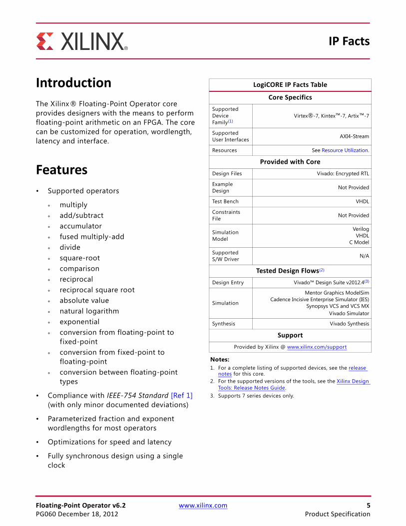
IntroductionThe Xilinx ® Floating-Point Operator core provides designers with the means to perform floating-point arithmetic on an FPGA. The core can be customized for operation, wordlength, latency and interface.
Features• Supported operators
° multiply
° add/subtract
° accumulator
° fused multiply-add
° divide
° square-root
° comparison
° reciprocal
° reciprocal square root
° absolute value
° natural logarithm
° exponential
° conversion from floating-point to fixed-point
° conversion from fixed-point to floating-point
° conversion between floating-point types
• Compliance with IEEE-754 Standard [Ref 1] (with only minor documented deviations)
• Parameterized fraction and exponent wordlengths for most operators
• Optimizations for speed and latency
• Fully synchronous design using a single clock
IP Facts
LogiCORE IP Facts Table
Core SpecificsSupported Device Family(1)
Virtex®-7, Kintex™-7, Artix™-7
Supported User Interfaces AXI4-Stream
Resources See Resource Utilization.
Provided with CoreDesign Files Vivado: Encrypted RTL
Example Design Not Provided
Test Bench VHDL
Constraints File Not Provided
Simulation Model
VerilogVHDL
C Model
Supported S/W Driver N/A
Tested Design Flows(2)
Design Entry Vivado™ Design Suite v2012.4(3)
Simulation
Mentor Graphics ModelSimCadence Incisive Enterprise Simulator (IES)
Synopsys VCS and VCS MXVivado Simulator
Synthesis Vivado Synthesis
SupportProvided by Xilinx @ www.xilinx.com/support
Notes: 1. For a complete listing of supported devices, see the release
notes for this core.2. For the supported versions of the tools, see the Xilinx Design
Tools: Release Notes Guide.3. Supports 7 series devices only.
Floating-Point Operator v6.2 www.xilinx.com 6PG060 December 18, 2012
Chapter 1
OverviewThe Xilinx® Floating-Point Operator core allows a range of floating-point arithmetic operations to be performed on FPGA. The operation is specif ied when the core is generated, and each operation variant has a common interface. This interface is shown in Figure 2-1.
Unsupported FeaturesSee Standards.
Licensing and Ordering InformationThis Xilinx LogiCORE™ IP module is provided at no additional cost with the Xilinx Vivado™ Design Suite under the terms of the Xilinx End User License. Information about this and other Xilinx LogiCORE IP modules is available at the Xilinx Intellectual Property page. For information about pricing and availability of other Xilinx LogiCORE IP modules and tools, contact your local Xilinx sales representative.

Floating-Point Operator v6.2 www.xilinx.com 7PG060 December 18, 2012
Chapter 2
Product Specification
Standards
IEEE-754 SupportThe Xilinx® Floating-Point Operator core complies with much of the IEEE-754 Standard [Ref 1]. The deviations generally provide a better trade-off of resources against functionality. Specif ically, the core deviates in the following ways:
• Non-Standard Wordlengths
• Denormalized Numbers
• Rounding Modes
• Signaling and Quiet NaNs
Non-Standard Wordlengths
The Xilinx Floating-Point Operator core supports a different range of fraction and exponent wordlength than defined in the IEEE-754 Standard.
Basic Formats:
• binary32 (Single Precision Format) – uses 32 bits, with a 24-bit fraction and 8-bit exponent.
• binary64 (Double Precision Format) – uses 64 bits, with 53-bit fraction and 11-bit exponent.
• binary128 (Quadruple Format) – not supported
Extendable Precision Formats (not available on all operators):
• Uses up to 80 bits.
• Exponent width of 4 to 16 bits.
• Fraction width of 4 to 64 bits
Note: Limitations apply based on exponent width. See the GUI for actual ranges.

Floating-Point Operator v6.2 www.xilinx.com 8PG060 December 18, 2012
Chapter 2: Product Specification
Denormalized Numbers
The exponent limits the size of numbers that can be represented. It is possible to extend the range for small numbers using the minimum exponent value (0) and allowing the fraction to become denormalized. That is, the hidden bit becomes zero such that
. Now the value is given by:
These denormalized numbers are extremely small. For example, with single precision the value is bounded . As such, in most practical calculation they do not contribute to the end result. Furthermore, as the denormalized value becomes smaller, it is represented with fewer bits and the relative rounding error introduced by each operation is increased.
The Xilinx Floating-Point Operator core does not support denormalized numbers for most operators. In FPGAs, the dynamic range can be increased using fewer resources by increasing the size of the exponent (and a 1-bit increase for single precision increases the range by ). If necessary, the overall wordlength of the format can be maintained by an associated decrease in the wordlength of the fraction.
To provide robustness, the core treats denormalized operands as zero with a sign taken from the denormalized number. Results that would have been denormalized are set to an appropriately signed zero.
The exception to the above rules is the absolute value operator, which propagates denormalized operands to the output.
The support for denormalized numbers cannot be switched off on some processors. Therefore, there might be very small differences between values generated by the Floating-Point Operator core and a program running on a conventional processor when numbers are very small. If such differences must be avoided, the arithmetic model on the conventional processor should include a simple check for denormalized numbers. This check should set the output of an operation to zero when denormalized numbers are detected to correctly reflect what happens in the FPGA implementation.
Rounding Modes
Only the default rounding mode, Round to Nearest (as defined by the IEEE-754 Standard [Ref 1]), is supported on most operators. This mode is often referred to as Round to Nearest Even, as values are rounded to the nearest representable value, with ties rounded to the nearest value with a zero least significant bit. The accumulator operator only supports Round Towards Zero.
b0b0.b1b2…bp 1– 1<
v 1–( )s22
we 1–2–
–0.b1b2…bwf 1–=
v 2 126–<
2256

Floating-Point Operator v6.2 www.xilinx.com 9PG060 December 18, 2012
Chapter 2: Product Specification
Signaling and Quiet NaNs
The IEEE-754 Standard requires provision of Signaling and Quiet NaNs. However, the Xilinx Floating-Point Operator core treats all NaNs as Quiet NaNs. When any NaN is supplied as one of the operands to the core, the result is a Quiet NaN, and an invalid operation exception is not raised (as would be the case for signaling NaNs). The exceptions to this rule are floating-point to f ixed-point conversion and the absolute value operator. For detailed information of the floating-point to f ixed-point conversion, see the behavior of INVALID_OP. For the absolute value operator, Signaling NaNs are propagated from input to output.
Accuracy of Results
Compliance to the IEEE-754 Standard requires that elementary arithmetic operations produce results accurate to half of one Unit in the Last Place (ULP). The Xilinx Floating-Point Operator satisf ies this requirement for the multiply, add/subtract, fused multiply-add, divide, square-root and conversion operators. The reciprocal, reciprocal square-root, natural logarithm and exponential operators produce results which are accurate to one ULP. The accuracy of the accumulator operator is variable. See Accumulator Design Guidelines.
Performance
LatencyThe latency of most operators can be set between 0 and a maximum value that is dependent upon the parameters chosen (1). The maximum latency of the Floating-Point Operator core for all operators can be found on the GUI.
The maximum latency of the divide and square root operations is Fraction Width + 4, and for compare operation it is two cycles. The float-to-float conversion operation is three cycles when either fraction or exponent width is being reduced; otherwise it is two cycles. It is two cycles, even when the input and result widths are the same, as the core provides conditioning in this situation. For more information, see Operation Selection.
1. The accumulator operator has a minimum latency of 1 clock cycle.

Floating-Point Operator v6.2 www.xilinx.com 10PG060 December 18, 2012
Chapter 2: Product Specification
Resource UtilizationThe resource requirements and maximum clock rates for the Floating-Point Operator core achievable on Kintex™-7, and Artix™-7 FPGAs are summarized as follows for the case of maximum latency and no aresetn or aclken pins. Unless otherwise stated, Non-Blocking flow control is used for all configurations. For selected use cases, f igures are provided for the Blocking and Performance flow control configuration which permits backpressure.
Note: Both LUT and FF resource usage and maximum frequency reduce with latency. Minimizing latency minimizes resources.
The maximum clock frequency results were obtained by double-registering input and output ports to reduce dependence on I/O placement. The inner level of registers used a separate clock signal to measure the path from the input registers to the f irst output register through the core.
The resource usage results do not include the “characterization” registers and represent the true logic used by the core. LUT counts include SRL16s or SRL32s.
Clock frequency does not take clock jitter into account and should be derated by an amount appropriate to the clock source jitter specification.
The maximum achievable clock frequency and the resource counts might also be affected by other tool options, additional logic in the FPGA, using a different version of Xilinx tools, and other factors.
It is possible to improve performance of the Xilinx Floating-Point Operator within a system context by placing the operator within an area group. Placement of both the logic slices and XtremeDSP™ slices can be contained in this way. If multiply-add operations are used, then placing them in the same group can be helpful. Groups can also include any supporting logic to ensure that it is placed close to the operators.
All results were produced using Vivado™ Design Suite 2012.4.
Custom Format: 17-Bit Fraction and 24-Bit Total WordlengthThe resource requirements and maximum clock rates achievable with 17-bit fraction and 24-bit total wordlength on Kintex-7 are summarized in Table 2-2.
Table 2-1: Speed File Version
FPGA Family Speed File Version
Kintex-7 PRODUCTION 1.08a 2012-11-02
Artix-7 ADVANCED 1.06c 2012-11-02

Floating-Point Operator v6.2 www.xilinx.com 11PG060 December 18, 2012
Chapter 2: Product Specification
Table 2-2: Characterization of 17-Bit Fraction and 24-Bit Total Wordlength on Kintex-7 FPGA
Operation
Resources(1)Maximum Frequency
(MHz)(2)(3)
Embedded FPGA Logic Kintex-7
Type Number LUT-FFPairs LUTs FFs -1 Speed Grade
Multiply DSP48E1 (max usage) 2 171 53 168 463
DSP48E1 (full usage) 1 139 69 135 463
Logic (no usage) 389 316 400 435
Add/Subtract Logic (no usage) 421 290 440 549
Fused Multiply-Add DSP48E1 (full usage) 3 909 625 885 530
DSP48E1 (medium usage) 1 887 601 898 475
Accumulator(4) DSP48E1 (max usage) 5 993 565 991 413
DSP48E1 (full usage) 2 1002 581 1019 414
Logic (no usage) 1060 685 982 408
Fixed to float Int24 input 143 127 141 421
Float to fixed Int24 result 190 132 190 621
Float to float Single to 24-17 format 94 27 87 566
24-17 to single 54 19 54 602
Compare Programmable 42 36 12 625
Divide RATE=1 685 447 899 499
RATE=19 201 166 169 390
Square Root RATE=1 448 262 518 595
RATE=18 156 103 149 573
Absolute Value(5) Any width 0 0 0 0 625
MultiplyFlow Control: Blocking, Optimize Goal: Performance
DSP48E1 (max usage) 2 313 145 301 463

Floating-Point Operator v6.2 www.xilinx.com 12PG060 December 18, 2012
Chapter 2: Product Specification
The resource requirements and maximum clock rates achievable with 17-bit fraction and 24-bit total wordlength on Artix-7 are summarized in Table 2-3.
Add/SubtractFlow Control: Blocking, Optimize Goal: Performance
Logic (no usage) 542 389 578 531
Notes: 1. The device used for these f igures is an XC7K70T-1.2. Area and maximum clock frequencies are provided as a guide and might vary with new releases of the Xilinx
implementation tools.3. Maximum clock frequencies are shown in MHz. Clock frequency does not take jitter into account and should be
de-rated by an amount appropriate to the clock source jitter specif ication.4. The accumulator operator has been configured with the following parameter values: Accumulator MSB = 30;
Accumulator LSB = -20; Input MSB = 30.5. The absolute value operator uses neither logic or registers so does not become the critical path in any realistic
circuit.
Table 2-2: Characterization of 17-Bit Fraction and 24-Bit Total Wordlength on Kintex-7 FPGA (Cont’d)
Operation
Resources(1)Maximum Frequency
(MHz)(2)(3)
Embedded FPGA Logic Kintex-7
Type Number LUT-FFPairs LUTs FFs -1 Speed Grade
Table 2-3: Characterization of 17-Bit Fraction and 24-Bit Total Wordlength on Artix-7 FPGAs
Operation
Resources(1)Maximum Frequency
(MHz)(2)(3)
Embedded FPGA Logic Artix-7
Type Number LUT-FF Pairs LUTs FFs -1 Speed Grade
Multiply DSP48E1 (max usage)
2 174 53 168 350
DSP48E1 (full usage) 1 135 69 135 376
Logic (no usage) 387 316 400 276
Add/Subtract Logic (no usage) 418 290 440 354
Fused Multiply-Add DSP48E1 (full usage) 3 896 626 885 356
DSP48E1 (medium usage)
1 926 599 898 317
Accumulator(4) DSP48E1 (max usage)
5 1005 562 991 280
DSP48E1 (full usage) 2 1051 580 1019 277
Logic (no usage) 1018 681 982 256

Floating-Point Operator v6.2 www.xilinx.com 13PG060 December 18, 2012
Chapter 2: Product Specification
Single-Precision FormatThe resource requirements and maximum clock rates achievable with single-precision format on Kintex-7 FPGAs is summarized in Table 2-4.
Fixed to float Int24 input 151 127 141 297
Float to fixed Int24 result 186 132 190 374
Float to float Single to 24-17 format 86 27 87 368
24-17 to single 49 19 54 460
Compare Programmable 43 37 12 409
Divide RATE=1 713 447 899 351
RATE=19 201 166 169 245
Square Root RATE=1 443 262 518 375
RATE=18 156 103 149 360
Absolute Value(5) Any width 0 0 0 0 464
MultiplyFlow Control: Blocking, Optimize Goal: Performance
DSP48E1 (max usage) 2 308 145 301 346
Add/SubtractFlow Control: Blocking, Optimize Goal: Performance
Logic (no usage) 546 389 578 337
Notes: 1. The device used for these f igures is an XC7A100T-1.2. Area and maximum clock frequencies are provided as a guide and might vary with new releases of the Xilinx
implementation tools.3. Maximum clock frequencies are shown in MHz. Clock frequency does not take jitter into account and should be
de-rated by an amount appropriate to the clock source jitter specif ication.4. The accumulator operator has been configured with the following parameter values: Accumulator MSB = 30;
Accumulator LSB = -20; Input MSB = 30.5. The absolute value operator uses no logic nor registers so does not become the critical path in any realistic circuit.
Table 2-3: Characterization of 17-Bit Fraction and 24-Bit Total Wordlength on Artix-7 FPGAs (Cont’d)
Operation
Resources(1)Maximum Frequency
(MHz)(2)(3)
Embedded FPGA Logic Artix-7
Type Number LUT-FF Pairs LUTs FFs -1 Speed Grade

Floating-Point Operator v6.2 www.xilinx.com 14PG060 December 18, 2012
Chapter 2: Product Specification
Table 2-4: Characterization of Single-Precision Format on Kintex-7 FPGAs
Operation
Resources(1)MaximumFrequency(MHz)(2)(3)
Embedded FPGA Logic 18K Block RAMs
Kintex-7
Type Number LUT-FFPairs LUTs FFs -1 Speed
Grade
Multiply DSP48E1 (max usage) 3 127 81 123 0 463
DSP48E1 (full usage) 2 192 89 196 0 463
DSP48E1 (medium usage) 1 357 242 373 0 463
Logic 674 574 683 0 462
Add/Subtract DSP48E1 (speed optimized, full usage) 2 354 238 342 0 463
Logic (speed optimized, no usage) 578 379 602 0 550
Logic (low latency) 656 500 668 0 447
Fused Multiply-Add DSP48E1 (full usage) 4 1283 802 1233 0 488
DSP48E1 (medium usage) 2 1246 766 1238 0 438
Accumulator(4) DSP48E1 (full usage) 5 1537 894 1551 0 410
DSP48E1 (medium usage) 2 1566 915 1588 0 412
Logic 1662 1097 1552 0 375
Fixed to float Int32 input 213 164 229 0 559
Float to fixed Int32 result 242 175 237 0 557
Float to float Single to double 70 21 70 0 625
Compare Programmable 51 48 12 0 624
Divide RATE=1 1252 777 1656 0 425
RATE=26 256 209 209 0 406
Square Root RATE=1 716 442 929 0 529
RATE=25 201 129 194 0 530
Reciprocal DSP48E1 (full usage) 8 365 149 404 0 414
Logic (no usage) 1604 1121 1756 0 418
Reciprocal Square Root DSP48E1 (full usage) 9 523 237 561 1 429
Logic (no usage) 2242 1825 2365 1 375
Absolute Value(5) N/A 0 0 0 0 625
Natural Logarithm DSP48E1 (full usage) 13 808 611 956 0 493
DSP48E1 (medium usage) 4 1059 804 1205 0 437
Logic 1639 1281 1827 0 421

Floating-Point Operator v6.2 www.xilinx.com 15PG060 December 18, 2012
Chapter 2: Product Specification
Exponential DSP48E1 (full usage) and BRAM (full usage) 7 594 359 623 2 458
DSP48E1 (full usage) 7 1089 827 660 0 410
DSP48E1 (medium usage) 1 1171 909 712 0 405
Logic 1641 1360 1174 0 377
MultiplyFlow Control: Blocking, Optimize Goal: Performance
DSP48E1 (max usage) 3 282 196 296 0 463
Add/SubtractFlow Control: Blocking, Optimize Goal: Performance
DSP48E1 (speed optimized,full usage) 2 502 360 520 0 463
Notes: 1. The device used for these f igures is an XC7K70T-1.2. Area and maximum clock frequencies are provided as a guide and might vary with new releases of the Xilinx implementation
tools.3. Maximum clock frequencies are shown in MHz. Clock frequency does not take jitter into account and should be de-rated by
an amount appropriate to the clock source jitter specif ication.4. The accumulator has been configured with the following parameter values; Accumulator MSB = 45; Accumulator LSB = -37;
Input MSB = 45.5. The absolute value operator uses no logic nor registers so does not become the critical path in any realistic circuit.
Table 2-4: Characterization of Single-Precision Format on Kintex-7 FPGAs (Cont’d)
Operation
Resources(1)MaximumFrequency(MHz)(2)(3)
Embedded FPGA Logic 18K Block RAMs
Kintex-7
Type Number LUT-FFPairs LUTs FFs -1 Speed
Grade

Floating-Point Operator v6.2 www.xilinx.com 16PG060 December 18, 2012
Chapter 2: Product Specification
The resource requirements and maximum clock rates achievable with single-precision format on Artix-7 FPGAs is summarized in Table 2-5.
Table 2-5: Characterization of Single-Precision Format on Artix-7 FPGAs
Operation
Resources(1)MaximumFrequency
(MHz)(2)(3)
Embedded FPGA Logic 18K Block RAMs
Artix-7
Type Number LUT-FFPairs LUTs FFs -1 Speed
Grade
Multiply DSP48E1 (max usage) 3 127 81 123 0 387
DSP48E1 (full usage) 2 203 89 196 0 347
DSP48E1 (medium usage) 1 376 242 373 0 320
Logic 684 574 683 0 308
Add/Subtract DSP48E1 (speed optimized, full usage)
2 345 238 342 0 357
Logic (speed optimized, no usage) 561 379 602 0 318
Logic (low latency) 630 499 668 0 295
Fused Multiply-Add DSP48E1 (full usage) 4 1274 805 1233 0 331
DSP48E1 (medium usage) 2 1232 763 1238 0 285
Accumulator(4) DSP48E1 (full usage) 5 1545 896 1551 0 279
DSP48E1 (medium usage) 2 1486 914 1588 0 277
Logic 1627 1102 1552 0 248
Fixed to float Int32 input 202 164 229 0 354
Float to fixed Int32 result 240 175 237 0 344
Float to float Single to double 61 21 70 0 445
Compare Programmable 51 48 12 0 396
Divide RATE=1 1225 777 1656 0 314
RATE=26 253 209 209 0 254
Square Root RATE=1 753 442 929 0 329
RATE=25 193 129 194 0 336
Reciprocal DSP48E1 (full usage) 8 369 148 404 0 279
Logic (no usage) 1523 1118 1756 0 284
Reciprocal Square Root
DSP48E1 (full usage) 9 528 237 561 1 280
Logic (no usage) 2259 1824 2365 1 240
Absolute Value(5) N/A 0 0 0 0 464

Floating-Point Operator v6.2 www.xilinx.com 17PG060 December 18, 2012
Chapter 2: Product Specification
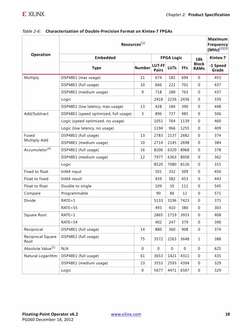
Double-Precision FormatThe resource requirements and maximum clock rates achievable with double-precision format on Kintex-7 FPGAs are summarized in Table 2-6.
Natural Logarithm DSP48E1 (full usage) 13 856 612 956 0 336
DSP48E1 (medium usage) 4 1096 804 1205 0 261
Logic 1620 1281 1827 0 281
Exponential DSP48E1 (full usage) and BRAM (full usage)
7 611 358 623 2 348
DSP48E1 (full usage) 7 1080 827 660 0 281
DSP48E1 (medium usage) 1 1188 909 712 0 280
Logic 1657 1359 1174 0 284
MultiplyFlow Control: Blocking, Optimize Goal: Performance
DSP48E1 (max usage) 3 303 196 296 0 363
Add/SubtractFlow Control: Blocking, Optimize Goal: Performance
DSP48E1 (speed optimized, full usage) 2 504 360 520 0 336
Notes: 1. The device used for these f igures is an XC7A100T-1.2. Area and maximum clock frequencies are provided as a guide and might vary with new releases of the Xilinx implementation
tools.3. Maximum clock frequencies are shown in MHz. Clock frequency does not take jitter into account and should be de-rated by
an amount appropriate to the clock source jitter specif ication.4. The accumulator has been configured with the following parameter values; Accumulator MSB = 45; Accumulator LSB = -37;
Input MSB = 45.5. The absolute value operator uses no logic nor registers so does not become the critical path in any realistic circuit.
Table 2-5: Characterization of Single-Precision Format on Artix-7 FPGAs (Cont’d)
Operation
Resources(1)MaximumFrequency
(MHz)(2)(3)
Embedded FPGA Logic 18K Block RAMs
Artix-7
Type Number LUT-FFPairs LUTs FFs -1 Speed
Grade
Floating-Point Operator v6.2 www.xilinx.com 18PG060 December 18, 2012
Chapter 2: Product Specification
Table 2-6: Characterization of Double-Precision Format on Kintex-7 FPGAs
Operation
Resources(1)MaximumFrequency(MHz)(2)(3)
Embedded FPGA Logic 18kBlockRAMs
Kintex-7
Type Number LUT-FFPairs LUTs FFs -1 Speed
Grade
Multiply DSP48E1 (max usage) 11 674 181 694 0 453
DSP48E1 (full usage) 10 666 221 701 0 437
DSP48E1 (medium usage) 9 718 280 763 0 437
Logic 2418 2236 2436 0 339
DSP48E1 (low latency, max usage) 13 428 184 390 0 448
Add/Subtract DSP48E1 (speed optimized, full usage) 3 896 737 985 0 506
Logic (speed optimized, no usage) 1051 764 1139 0 460
Logic (low latency, no usage) 1194 966 1255 0 409
Fused Multiply-Add
DSP48E1 (full usage) 13 2783 2137 2682 0 374
DSP48E1 (medium usage) 10 2714 2145 2698 0 384
Accumulator(4) DSP48E1 (full usage) 16 8206 6320 8968 0 378
DSP48E1 (medium usage) 12 7977 6363 8958 0 362
Logic 8520 7080 8126 0 315
Fixed to float Int64 input 501 332 509 0 456
Float to fixed Int64 result 459 382 453 0 443
Float to float Double to single 109 35 111 0 545
Compare Programmable 90 86 12 0 571
Divide RATE=1 5133 3196 7423 0 375
RATE=55 493 410 380 0 303
Square Root RATE=1 2865 1719 3933 0 408
RATE=54 402 247 379 0 390
Reciprocal DSP48E1 (full usage) 14 880 360 908 0 374
Reciprocal Square Root
DSP48E1 (full usage) 75 3572 2263 3648 1 388
Absolute Value(5) N/A 0 0 0 0 0 625
Natural Logarithm DSP48E1 (full usage) 61 3653 1421 4311 0 435
DSP48E1 (medium usage) 23 3553 2593 4394 0 329
Logic 0 5677 4471 6507 0 329

Floating-Point Operator v6.2 www.xilinx.com 19PG060 December 18, 2012
Chapter 2: Product Specification
Exponential DSP48E1 (full usage) and BRAM (full usage) 26 2072 1100 2251 5 446
DSP48E1 (full usage) 26 3007 2257 2303 0 397
DSP48E1 (medium usage) 15 3098 2503 2273 0 388
Logic 0 7201 6578 6387 0 317
MultiplyFlow Control: Blocking,Optimize Goal: Performance
DSP48E1 (max usage) 11 965 391 1028 0 447
Add/SubtractFlow Control: Blocking,Optimize Goal: Performance
DSP48E1 (speed optimized, full usage) 3 1204 949 1323 0 442
Notes: 1. The device used for these f igures is an XC7K70-1.2. Area and maximum clock frequencies are provided as a guide and might vary with new releases of the Xilinx
implementation tools.3. Maximum clock frequencies are shown in MHz. Clock frequency does not take jitter into account and should be de-rated by
an amount appropriate to the clock source jitter specif ication.4. The accumulator operator has been configured with the following parameter values; Accumulator MSB = 269; Accumulator
LSB = -268; Input MSB = 269.5. The absolute value operator uses no logic nor registers so does not become the critical path in any realistic circuit.
Table 2-6: Characterization of Double-Precision Format on Kintex-7 FPGAs (Cont’d)
Operation
Resources(1)MaximumFrequency(MHz)(2)(3)
Embedded FPGA Logic 18kBlockRAMs
Kintex-7
Type Number LUT-FFPairs LUTs FFs -1 Speed
Grade
Floating-Point Operator v6.2 www.xilinx.com 20PG060 December 18, 2012
Chapter 2: Product Specification
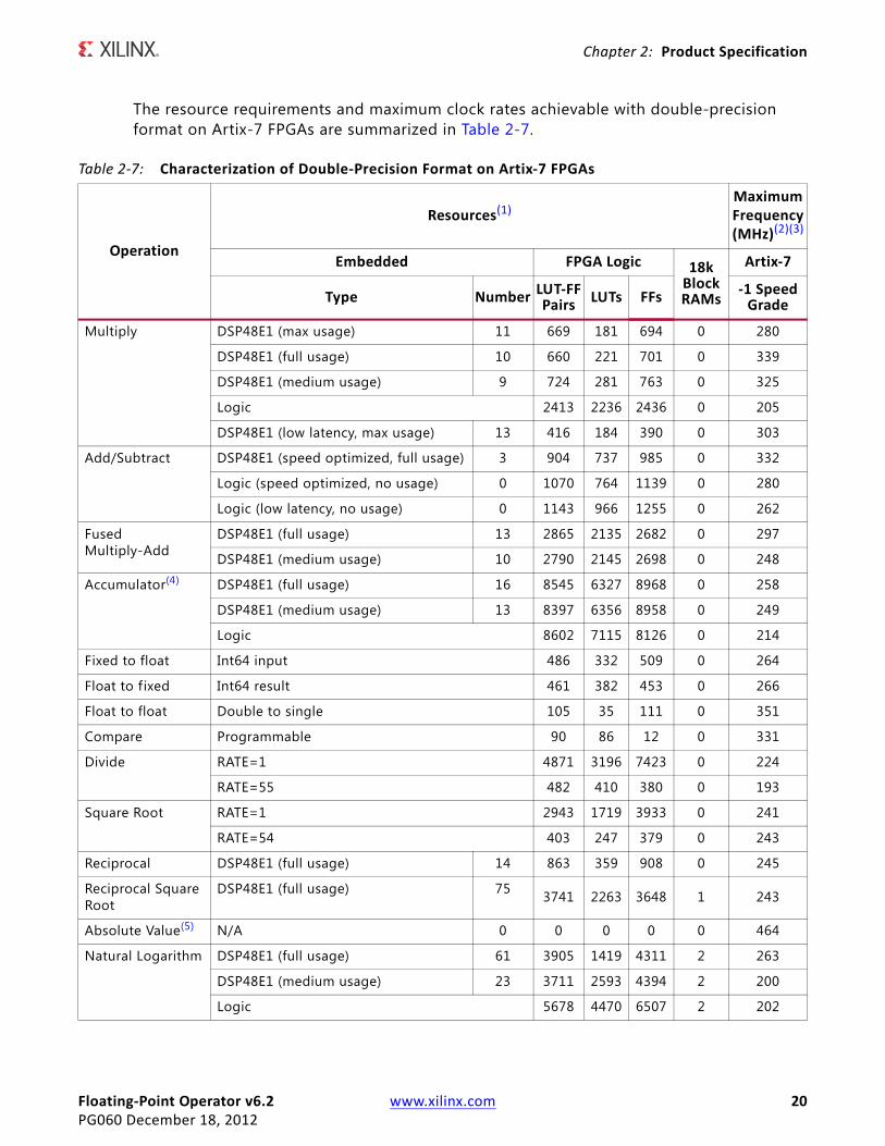
The resource requirements and maximum clock rates achievable with double-precision format on Artix-7 FPGAs are summarized in Table 2-7.
Table 2-7: Characterization of Double-Precision Format on Artix-7 FPGAs
Operation
Resources(1)MaximumFrequency(MHz)(2)(3)
Embedded FPGA Logic 18kBlockRAMs
Artix-7
Type Number LUT-FFPairs LUTs FFs -1 Speed
Grade
Multiply DSP48E1 (max usage) 11 669 181 694 0 280
DSP48E1 (full usage) 10 660 221 701 0 339
DSP48E1 (medium usage) 9 724 281 763 0 325
Logic 2413 2236 2436 0 205
DSP48E1 (low latency, max usage) 13 416 184 390 0 303
Add/Subtract DSP48E1 (speed optimized, full usage) 3 904 737 985 0 332
Logic (speed optimized, no usage) 0 1070 764 1139 0 280
Logic (low latency, no usage) 0 1143 966 1255 0 262
Fused Multiply-Add
DSP48E1 (full usage) 13 2865 2135 2682 0 297
DSP48E1 (medium usage) 10 2790 2145 2698 0 248
Accumulator(4) DSP48E1 (full usage) 16 8545 6327 8968 0 258
DSP48E1 (medium usage) 13 8397 6356 8958 0 249
Logic 8602 7115 8126 0 214
Fixed to float Int64 input 486 332 509 0 264
Float to fixed Int64 result 461 382 453 0 266
Float to float Double to single 105 35 111 0 351
Compare Programmable 90 86 12 0 331
Divide RATE=1 4871 3196 7423 0 224
RATE=55 482 410 380 0 193
Square Root RATE=1 2943 1719 3933 0 241
RATE=54 403 247 379 0 243
Reciprocal DSP48E1 (full usage) 14 863 359 908 0 245
Reciprocal Square Root
DSP48E1 (full usage) 75 3741 2263 3648 1 243
Absolute Value(5) N/A 0 0 0 0 0 464
Natural Logarithm DSP48E1 (full usage) 61 3905 1419 4311 2 263
DSP48E1 (medium usage) 23 3711 2593 4394 2 200
Logic 5678 4470 6507 2 202

Floating-Point Operator v6.2 www.xilinx.com 21PG060 December 18, 2012
Chapter 2: Product Specification
Exponential DSP48E1 (full usage) and BRAM (full usage) 26 2093 1100 2251 5 261
DSP48E1 (full usage) 26 3091 2257 2303 0 261
DSP48E1 (medium usage) 15 3179 2503 2273 0 240
Logic 7328 6583 6387 0 199
MultiplyFlow Control: Blocking,Optimize Goal: Performance
DSP48E1 (max usage) 11 981 391 1028 0 329
Add/SubtractFlow Control: Blocking,Optimize Goal: Performance
DSP48E1 (speed optimized, full usage) 3 1190 949 1323 0 321
Notes: 1. The device used for these f igures is an XC7A100T-1.2. Area and maximum clock frequencies are provided as a guide and might vary with new releases of the Xilinx implementation
tools.3. Maximum clock frequencies are shown in MHz. Clock frequency does not take jitter into account and should be de-rated by
an amount appropriate to the clock source jitter specif ication.4. The accumulator operator has been configured with the following parameter values; Accumulator MSB = 269; Accumulator
LSB = -268; Input MSB = 269.5. The absolute value operator uses no logic nor registers so does not become the critical path in any realistic circuit.
Table 2-7: Characterization of Double-Precision Format on Artix-7 FPGAs (Cont’d)
Operation
Resources(1)MaximumFrequency(MHz)(2)(3)
Embedded FPGA Logic 18kBlockRAMs
Artix-7
Type Number LUT-FFPairs LUTs FFs -1 Speed
Grade

Floating-Point Operator v6.2 www.xilinx.com 22PG060 December 18, 2012
Chapter 2: Product Specification
Port Descriptions
The ports employed by the core are shown in Figure 2-1. They are described in more detail in Table 2-8. All control signals are active-High with the exception of aresetn.
X-Ref Target - Figure 2-1
Figure 2-1: Core Schematic Symbol

Floating-Point Operator v6.2 www.xilinx.com 23PG060 December 18, 2012
Chapter 2: Product Specification
All AXI4-Stream port names are lower case, but for ease of visualization, upper case is used in this document when referring to port name suff ixes, such as TDATA or TLAST.
Table 2-8: Core Signal Pinout
Name Direction Description
aclk Input Rising-edge clock
aclken Input Active-High clock enable (optional)
aresetn Input Active-Low synchronous clear (optional), always takes priority over aclken). This signal must be asserted for a minimum of 2 clock cycles.
s_axis_a_tvalid Input TVALID for channel A
s_axis_a_tready Output TREADY for channel A
s_axis_a_tdata Input TDATA for channel A. See TDATA Packing for internal structure
s_axis_a_tuser Input TUSER for channel A
s_axis_a_tlast Input TLAST for channel A
s_axis_b_tvalid Input TVALID for channel B
s_axis_b_tready Output TREADY for channel B
s_axis_b_tdata Input TDATA for channel B. See TDATA Packing for internal structure
s_axis_b_tuser Input TUSER for channel B
s_axis_b_tlast Input TLAST for channel B
s_axis_c_tvalid Input TVALID for channel C
s_axis_c_tready Output TREADY for channel C
s_axis_c_tdata Input TDATA for channel C. See TDATA Packing for internal structure
s_axis_c_tuser Input TUSER for channel C
s_axis_c_tlast Input TLAST for channel C
s_axis_operation_tvalid Input TVALID for channel OPERATION
s_axis_operation_tready Output TREADY for channel OPERATION
s_axis_operation_tdata Input TDATA for channel OPERATION. See TDATA Packing for internal structure
s_axis_operation_tuser Input TUSER for channel OPERATION
s_axis_operation_tlast Input TLAST for channel OPERATION
m_axis_result_tvalid Output TVALID for channel RESULT
m_axis_result_tready Input TREADY for channel RESULT
m_axis_result_tdata Output TDATA for channel RESULT. See TDATA Subfield for internal structure
m_axis_result_tuser Output TUSER for channel RESULT
m_axis_result_tlast Output TLAST for channel RESULT

Floating-Point Operator v6.2 www.xilinx.com 24PG060 December 18, 2012
Chapter 2: Product Specification
A Channel (s_axis_a_tdata)
Operand A input.
B Channel (s_axis_b_tdata)
Operand B input.
C Channel (s_axis_c_tdata)
Operand C input.
aclk
All signals are synchronous to the aclk input.
aclken
When aclken is deasserted, the clock is disabled, and the state of the core and its outputs are maintained.
Note: aresetn takes priority over aclken.
aresetn
When aresetn is asserted, the core control circuits are synchronously set to their initial state. Any incomplete results are discarded, and m_axis_result_tvalid is not generated for them. While aresetn is asserted m_axis_result_tvalid is synchronously deasserted. The core is ready for new input one cycle after aresetn is deasserted (1), at which point slave channel tvalids are asserted. aresetn takes priority over aclken. If aresetn is required to be gated by aclken, then this can be done externally to the core.
IMPORTANT: aresetn must be driven low for a minimum of two clock cycles to reset the core.
Operation Channel (s_axis_operation_tdata)
The operation channel is present when add and subtract operations are selected together, or when a programmable comparator is selected. The operations are binary encoded as specified in Table 2-9.
1. See the warning described in Non-Blocking Mode.

Floating-Point Operator v6.2 www.xilinx.com 25PG060 December 18, 2012
Chapter 2: Product Specification
Result Channel (m_axis_result_tdata)
If the operation is compare, then the valid bits within the result depend upon the compare operation selected. If the compare operation is one of those listed in Table 2-9, then only the least signif icant bit of the result indicates whether the comparison is TRUE or FALSE. If the operation is condition code, then the result of the comparison is provided by 4-bits using the encoding summarized in Table 2-10.
The following flag signals provide exception information. Additional detail on their behavior can be found in the IEEE-754 Standard. The exception flags are not presented as discrete signals in Floating-Point Operator v6.2, but instead are provided in the RESULT channel m_axis_result_tuser subfield. For more details, see Output Result Channel.
The accumulator operator adds two non-standard exception flags: Accumulator Input Overflow, and Accumulator Overflow. For more information about these flags, see Accumulator Design Guidelines.
Table 2-9: Encoding of s_axis_operation_tdata
FP Operation s_axis_operation_tdata(5 : 0)Add 000000
Subtract 000001
Compare(Programmable)
Unordered(1) 000100
Less Than 001100
Equal 010100
Less Than or Equal 011100Greater Than 100100
Not Equal 101100
Greater Than or Equal 1101001. An unordered comparison returns TRUE when either (or both) of the operands are NaN, indicating that the
operands’ magnitudes cannot be put in size order.
Table 2-10: Condition Code Summary
Compare Operationm_axis_result_tdata(3 : 0)
Result3 2 1 0
Programmable 0 A OP B = FALSE
1 A OP B = TRUE
Condition Code Unordered > < EQ Meaning
0 0 0 1 A = B
0 0 1 0 A < B
0 1 0 0 A > B
1 0 0 0 A, B or both are NaN.
Floating-Point Operator v6.2 www.xilinx.com 26PG060 December 18, 2012
Chapter 2: Product Specification
UNDERFLOW
Underflow is signaled when the operation generates a non-zero result which is too small to be represented with the chosen precision. The result is set to zero. Underflow is detected after rounding.
Note: A number that becomes denormalized before rounding is set to zero and underflow signaled.
OVERFLOW
Overflow is signaled when the operation generates a result that is too large to be represented with the chosen precision. For most operators, the output is set to a correctly signed .
Due to its different rounding mode, the accumulator operator sets the output to the target format's largest f inite number with the sign of the pre-rounded result.
INVALID_OP
Invalid general-computational or signaling-computational operations are signaled when the operation performed is invalid. According to the IEEE-754 Standard [Ref 1], the following are invalid operations:
1. Any operation on a signaling NaN. (This is not relevant to the core as all NaNs are treated as Quiet NaNs).
2. Addition or subtraction of infinite values where the sign of the result cannot be determined. For example, magnitude subtraction of infinities such as (+ ) +(- ).
3. Multiplication, or fused multiply-add, where .
4. Division where 0/0 or ∞/∞.
5. Square root if the operand is less than zero. A special case is sqrt(-0), which is defined to be -0 by the IEEE-754 Standard.
6. When the input of a conversion precludes a faithful representation that cannot otherwise be signaled (for example NaN or infinity).
7. Natural Logarithm if the input is less than 0. A special case is log(-0) which is defined to be - .
When an invalid operation occurs, the associated result is a Quiet NaN. In the case of floating-point to f ixed-point conversion, NaN and infinity raise an invalid operation exception. If the operand is out of range, or an infinity, then an overflow exception is raised. By analyzing the two exception signals it is possible to determine which of the three types of operand was converted. (See Table 2-11.)
∞
∞ ∞
0 ∞×
∞

Floating-Point Operator v6.2 www.xilinx.com 27PG060 December 18, 2012
Chapter 2: Product Specification
When the operand of a Floating-point to f ixed-point conversion is a NaN, the result is set to the most negative representable number. When the operand is infinity or an out-of-range floating-point number, the result is saturated to the most positive or most negative number, depending upon the sign of the operand.
Note: Floating-point to f ixed-point conversion does not treat a NaN as a Quiet NaN, because NaN is not representable within the resulting f ixed-point format, and so can only be indicated through an invalid operation exception.
The absolute value operator does not signal an invalid operation when a Signaling NaN is input, as it is not a general computational or a signaling computational operation.
Note: The fused multiply-add operator does not signal an invalid operation when + Quiet NaN is performed.
DIVIDE_BY_ZERO
DIVIDE_BY_ZERO is asserted when a divide operation is performed where the divisor is zero and the dividend is a f inite non-zero number. The result in this circumstance is a correctly signed infinity.
DIVIDE_BY_ZERO is asserted when a logarithm operation is performed where the operand is zero. The result in this circumstance is negative infinity.
Table 2-11: Invalid Operation Summary
Operand Invalid Operation Overflow Result
+ Out of Range 0 1 011...11
- Out of Range 0 1 100...00
+ Infinity 1 1 011...11
- Infinity 1 1 100...00
NaN 1 0 100...00
0 ∞×

Floating-Point Operator v6.2 www.xilinx.com 28PG060 December 18, 2012
Chapter 3
Designing with the CoreThis chapter includes guidelines and additional information to make designing with the core easier.
General Design GuidelinesThe floating-point and fixed-point representations employed by the core are described in Floating-Point Number Representation and Fixed-Point Number Representation.
Floating-Point Number RepresentationThe core employs a floating-point representation that is a generalization of the IEEE-754 Standard [Ref 1] to allow for non-standard sizes. When standard sizes are chosen, the format and special values employed are identical to those described by the IEEE-754 Standard.
Two parameters have been adopted for the purposes of generalizing the format employed by the Floating-Point Operator core. These specify the total format width and the width of the fractional part. For standard single precision types, the format width is 32 bits and fraction width 24 bits. In the following description, these widths are abbreviated to and
, respectively.
A floating-point number is represented using a sign, exponent, and fraction (which are denoted as ’s,’ ’E,’ and , respectively).
The value of a floating-point number is given by:
The binary bits, , have weighting , where the most signif icant bit is a constant 1. As such, the combination is bounded such that and the number is said to be normalized. To provide increased dynamic range, this quantity is scaled by a positive or negative power of 2 (denoted here as E). The sign bit provides a value that is negative when , and positive when .
The binary representation of a floating-point number contains three fields as shown in Figure 3-1.
wwf
b0.b1b2…bwf 1–
v 1–( )s2Eb0.b1b2…bwf 1–=
bi 2 i– b01 b0.b1b2…bp 1– 2<≤
s 1= s 0=

Floating-Point Operator v6.2 www.xilinx.com 29PG060 December 18, 2012
Chapter 3: Designing with the Core
As is a constant, only the fractional part is retained, that is, . This requires only bits. Of the remaining bits, one bit is used to represent the sign, and bits represent the exponent.
The exponent f ield, , employs a biased unsigned integer representation, whose value is given by:
The index, i, of each bit within the exponent field is shown in Figure 3-1.
The signed value of the exponent, , is obtained by removing the bias, that is,.
In reality, is not the wordlength of the fraction, but the fraction with the hidden bit, , included. This terminology has been adopted to provide commonality with that used to describe f ixed-point parameters (as employed by Xilinx System Generator™ for DSP).
Special Values
Several values for , and have been reserved for representing special numbers, such as Not a Number (NaN), Infinity ( ), Zero (0), and denormalized numbers (see Denormalized Numbers for an explanation of the latter). These special values are summarized in Table 3-1.
X-Ref Target - Figure 3-1
Figure 3-1: Bit Fields within the Floating-Point Representation
fes
3 wf -11 2we-1 0
0wf -2wf -1w -1
w
wf -1Bit position
Bit significance (i)
DS335_02_050609
b0 f b1…bwf 1–=
wf 1– we w wf–=
e
e ei2i
i 0=
we 1–
=
E
E e 2we 1–
1–( )–=
wf b0
s e f∞

Floating-Point Operator v6.2 www.xilinx.com 30PG060 December 18, 2012
Chapter 3: Designing with the Core
In Table 3-1 the sign bit is undefined when a result is a NaN. The core generates NaNs with the sign bit set to 0 (that is, positive). Also, infinity and zero are signed. Where possible, the sign is handled in the same way as finite non-zero numbers. For example, ,
and . A meaningless operation such as raises an invalid operation exception and produces a NaN as a result.
Fixed-Point Number RepresentationFor the purposes of f ixed-point to floating-point conversion, a f ixed-point representation is adopted that is consistent with the signed integer type used by Xilinx System Generator for DSP. Fixed-point values are represented using a two’s complement number that is weighted by a f ixed power of 2. The binary representation of a fixed-point number contains three f ields as shown in Figure 3-2 (although it is still a weighted two’s complement number).
In Figure 3-2, the bit position has been labeled with an index i. Based upon this, the value of a fixed-point number is given by:
Table 3-1: Special Values
Symbol for Special Value s Field e Field f Field
NaN don’t care -1 (that is, )
Any non-zero field.For results that are NaN the most signif icant bit of fraction is set (that is, )
sign of -1 (that is, )Zero (that is, )
sign of 0 Zero (that is, )
denormalized sign of number 0 Any non-zero field
X-Ref Target - Figure 3-2
Figure 3-2: Bit Fields within the Fixed-Point Representation
2we 1–
e 11...11=
f 10...00=
∞± ∞ 2we 1–
e 11...11=f 00...00=
0± 0 f 00...00=
0– 0–( )+ 0–=
0– 0+ 0= ∞– ∞–( )+ ∞–= ∞– ∞+
fractionintegers
0wf -1wf w -1
w
wf -1Bit position (i)
DS335_03_050609
v 1–( )s2w 1– wf–
bw 2– …bwf.bwf 1– …b1b0+=
Floating-Point Operator v6.2 www.xilinx.com 31PG060 December 18, 2012
Chapter 3: Designing with the Core
For example, a 32-bit signed integer representation is obtained when a total width of 32 and a fraction width of 0 are specif ied. Round to Nearest is employed within the conversion operations.
To provide for the sign bit, the width of the integer f ield must be at least 1, requiring that the fractional width be no larger than w-1.
Accumulator Design Guidelines
Configuring the AccumulatorThe accumulator operator has been implemented as a floating-point wrapper around a f ixed point accumulator to reduce resources and to allow a throughput of one sample per clock cycle. Three parameters are required to configure the accumulator:
• Input MSB – The MSB of the largest number that can be accepted.
• LSB – The LSB of the smallest number that can be accepted. It is also the LSB of the accumulated result.
• MSB – The MSB of the largest result. It can be up to 54 bits greater than the Input MSB.
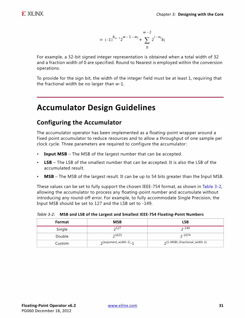
These values can be set to fully support the chosen IEEE-754 format, as shown in Table 3-2, allowing the accumulator to process any floating-point number and accumulate without introducing any round-off error. For example, to fully accommodate Single Precision, the Input MSB should be set to 127 and the LSB set to -149.
Table 3-2: MSB and LSB of the Largest and Smallest IEEE-754 Floating-Point Numbers
Format MSB LSB
Single 2127 2-149
Double 21023 2-1074
Custom 2(exponent_width-1)-1 2(1-MSB)-(fractional_width-1)
1–( )bw 1– 2
w 1– wf–2
i wf–bi
0
w 2–
+=

Floating-Point Operator v6.2 www.xilinx.com 32PG060 December 18, 2012
Chapter 3: Designing with the Core
Resource usage can be reduced if these parameters are set to match the bounds on the dataset that is used with the accumulator. For example, if the largest value that will be accumulated is 100,000 then the MSB can be set to 17, substantially reducing the width of the accumulator.
The LSB controls the accuracy of the accumulator. Input values with an LSB smaller than the LSB of the accumulator are truncated (Round Towards Zero) introducing a maximum error of 2LSB-1 per accumulation. In the worst case, the lower log2(n) bits of the accumulator are incorrect after n such accumulations. If accuracy to 2x is required after n accumulations then the LSB needs to be set to . For example, if accuracy to 2-16 is required after 1000 accumulations, the LSB needs to be set to .
The MSB of the accumulator sets the maximum value that can be accumulated. The set value can be up to 54 bits greater than the Input MSB, which allows one number to be accumulated every clock cycle for one year at 400 MHz. If the MSB is set to be greater than the maximum value of the IEEE-754 format then the result can cause an IEEE-754 overflow unless sufficient subtractions occur to bring it back into range (this is for a positive accumulated value. For a negative accumulated value, suff icient additions need to occur.)
Denormalized NumbersThe accumulator is consistent with the other operators in its handling of denormalized values. Denormalized numbers seen on the input are flushed to zero. Denormalized numbers on the output are flushed to zero and the Underflow flag is set. However, denormalized numbers generated in the accumulator are retained within the accumulator to maintain accuracy.
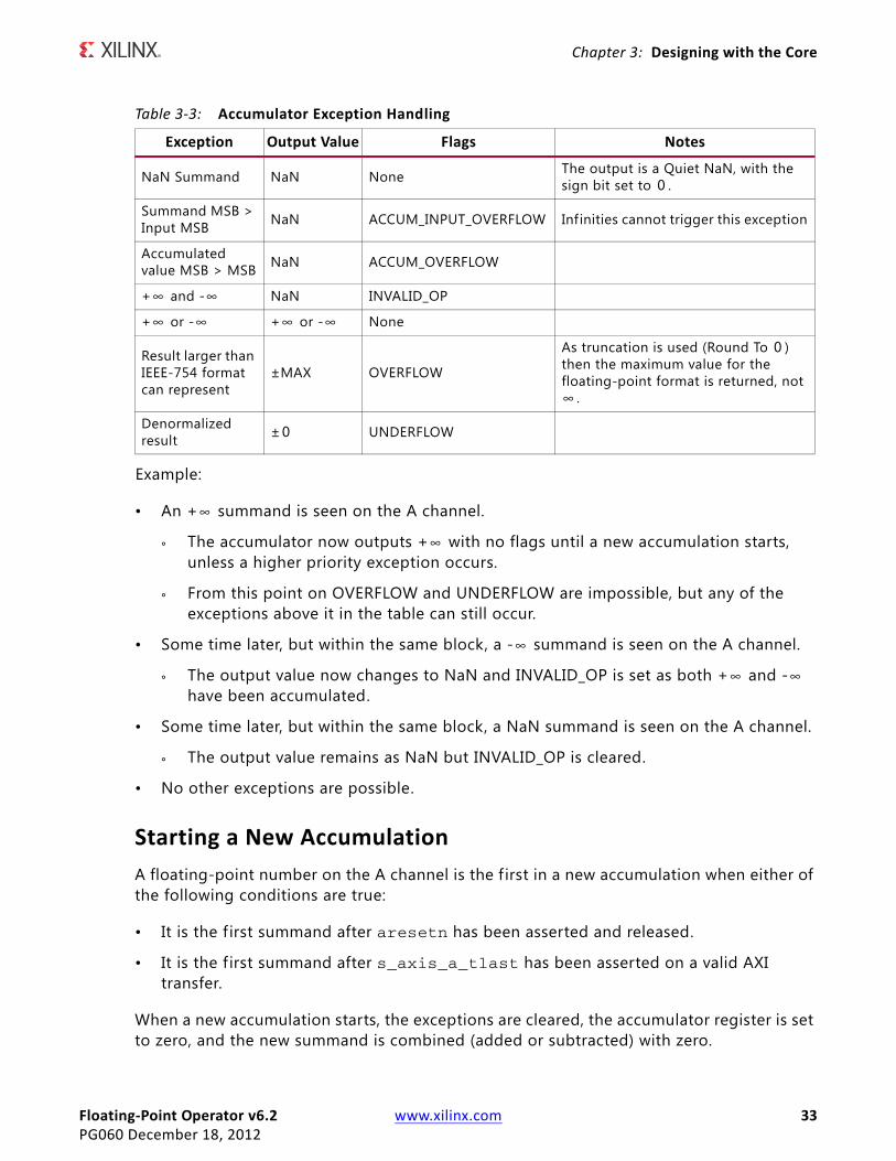
ExceptionsThe accumulator handles exceptions in order shown in Table 3-3. All exceptions except for OVERFLOW and UNDERFLOW are unrecoverable. (1)
After an unrecoverable exception occurs, the output value and flags remain set until a new accumulation is started. The output value and flags can subsequently change if an exception above it in the table occurs.
1. OVERFLOW and UNDERFLOW represent the state of the accumulated value after it has been converted to a floating-point number. Following operations might bring the accumulator back into a valid range so these exceptions are handled on a per-output basis. All other exceptions represent the state of the accumulator itself and recovery is only possible by ending the accumulation.
x N( )2log–
16– 1000( )2log– 26–=
Floating-Point Operator v6.2 www.xilinx.com 33PG060 December 18, 2012
Chapter 3: Designing with the Core
Example:
• An + summand is seen on the A channel.
° The accumulator now outputs + with no flags until a new accumulation starts, unless a higher priority exception occurs.
° From this point on OVERFLOW and UNDERFLOW are impossible, but any of the exceptions above it in the table can still occur.
• Some time later, but within the same block, a - summand is seen on the A channel.
° The output value now changes to NaN and INVALID_OP is set as both + and - have been accumulated.
• Some time later, but within the same block, a NaN summand is seen on the A channel.
° The output value remains as NaN but INVALID_OP is cleared.
• No other exceptions are possible.
Starting a New AccumulationA floating-point number on the A channel is the f irst in a new accumulation when either of the following conditions are true:
• It is the f irst summand after aresetn has been asserted and released.
• It is the f irst summand after s_axis_a_tlast has been asserted on a valid AXI transfer.
When a new accumulation starts, the exceptions are cleared, the accumulator register is set to zero, and the new summand is combined (added or subtracted) with zero.
Table 3-3: Accumulator Exception Handling
Exception Output Value Flags Notes
NaN Summand NaN None The output is a Quiet NaN, with the sign bit set to .
Summand MSB > Input MSB NaN ACCUM_INPUT_OVERFLOW Infinities cannot trigger this exception
Accumulated value MSB > MSB NaN ACCUM_OVERFLOW
+ and - NaN INVALID_OP
+ or - + or - None
Result larger than IEEE-754 format can represent
±MAX OVERFLOW
As truncation is used (Round To ) then the maximum value for the floating-point format is returned, not
.
Denormalized result ± UNDERFLOW
0
∞ ∞
∞ ∞ ∞ ∞
0
∞
0
∞
∞
∞
∞ ∞

Floating-Point Operator v6.2 www.xilinx.com 34PG060 December 18, 2012
Chapter 3: Designing with the Core
ClockingThe Floating-Point Operator core uses a single clock, called aclk . All input and output interfaces and internal state are subject to this single clock.
ResetsThe Floating-Point Operator core uses a single, optional, reset input called aresetn. This signal is active-Low and must be asserted for a minimum of two clock cycles to ensure correct operation. aresetn is a global synchronous reset which resets all control states in the core; all data in transit through the core is lost when aresetn is asserted.
Protocol Description
AXI4-Stream ConsiderationsThe conversion to AXI4-Stream interfaces brings standardization and enhances interoperability of Xilinx IP LogiCORE™ solutions. Other than general control signals such as aclk , aclken and aresetn, all inputs and outputs to and from the Floating-Point Operator core are conveyed using AXI4-Stream channels. A channel consists of TVALID and TDATA always, plus several optional ports and fields. In the Floating-Point Operator, the optional ports supported are TREADY, TLAST and TUSER. Together, TVALID and TREADY perform a handshake to transfer a message, where the payload is TDATA, TUSER and TLAST. The Floating-Point Operator operates on the operands contained in the TDATA fields and outputs the result in the TDATA field of the output channel. The Floating-Point Operator does not use TUSER and TLAST inputs as such, (1) but the core provides the facility to convey these fields with the same latency as for TDATA. This facility is expected to ease use of the Floating-Point Operator in a system. For example, the Floating-Point Operator might be operating on streaming packetized data. In this example, the core could be configured to pass the TLAST of the packetized data channel, thus saving the system designer the effort of constructing a bypass path for this information. For further details on AXI4-Stream interfaces see [Ref 6] and [Ref 7].
1. The accumulator does use TLAST as an input. For more information, see TLAST in the Accumulator Operator.

Floating-Point Operator v6.2 www.xilinx.com 35PG060 December 18, 2012
Chapter 3: Designing with the Core
Basic Handshake
Figure 3-3 shows the transfer of data in an AXI4-Stream channel. TVALID is driven by the source (master) side of the channel and TREADY is driven by the receiver (slave). TVALID indicates that the value in the payload f ields (TDATA, TUSER and TLAST) is valid. TREADY indicates that the slave is ready to receive data. When both TVALID and TREADY are TRUE in a cycle, a transfer occurs. The master and slave set TVALID and TREADY respectively for the next transfer appropriately.
Non-Blocking Mode
The term Non-Blocking means that lack of data on one input channel does not block the execution of an operation if data is received on another input channel. The full flow control of AXI4-Stream is not always required. Blocking or Non-Blocking behavior is selected using the Flow Control parameter or GUI field. The core supports a Non-Blocking mode in which the AXI4-Stream channels do not have TREADY, that is, they do not support back pressure. The choice of Blocking or Non-Blocking applies to the whole core, not each channel individually. Channels still have the non-optional TVALID signal, which is analogous to the New Data (ND) signal on many cores prior to the adoption of AXI4-Stream interfaces. Without the facility to block dataflow, the internal implementation is much simplif ied, so fewer resources are required for this mode.
RECOMMENDED: This mode is recommended when moving to this core version from a pre-AXI4-Stream core with minimal change.
When all of the present input channels receive an active TVALID, an operation is validated and the output TVALID (suitably delayed by the latency of the core) is asserted to qualify the result. Operations occur on every enabled clock cycle and data is presented on the output channel payload f ields regardless of TVALID. This is to allow a minimal migration from previous core versions. Figure 3-4 shows the Non-Blocking behavior for a case of an adder with latency of one cycle.
IMPORTANT: For performance, aresetn is registered internally, which delays its action by a clock cycle. The effect of this is that any transaction input in the cycle following the de-assertion of aresetn
X-Ref Target - Figure 3-3
Figure 3-3: Data Transfer in an AXI4-Stream Channel
ACLK
TVALID
TREADY
TDATA
TLAST
TUSER
D1 D2 D3 D4
L1 L2 L3 L4
U1 U2 U3 U4

Floating-Point Operator v6.2 www.xilinx.com 36PG060 December 18, 2012
Chapter 3: Designing with the Core
is reset by the action of aresetn, resulting in an output data value of zero. m_axis_result_tvalid is also inactive for this cycle.
Blocking Mode
The term Blocking means that operation execution does not occur until fresh data is available on all input channels. The full flow control of AXI4-Stream aids system design because the flow of data is self-regulating. Data loss is prevented by the presence of back pressure (TREADY), so that data is only propagated when the downstream datapath is ready to process the data.
The Floating-Point Operator has one, two or three input channels and one output channel. When all input channels have validated data available, an operation occurs and the result becomes available on the output. If the output is prevented from off-loading data because TREADY is low then data accumulates in the output buffer internal to the core. When this output buffer is nearly full the core stops further operations. This prevents the input buffers from off-loading data for new operations so the input buffers f ill as new data is input. When the input buffers f ill, their respective TREADYs are deasserted to prevent further input. This is the normal action of back pressure.
The inputs are tied in the sense that each must receive validated data before an operation is prompted. Therefore, there is an additional blocking mechanism, where at least one input channel does not receive validated data while others do. In this case, the validated data is stored in the input buffer of the channel.
After a few cycles of this scenario, the buffer of the channel receiving data f ills and TREADY for that channel is deasserted until the starved channel receives some data. Figure 3-5 shows both blocking behavior and back pressure for the case of an adder. The first data on channel A is paired with the f irst data on channel B, the second with the second and so on. This demonstrates the ‘blocking’ concept. The diagram further shows how data output is delayed not only by latency, but also by the handshake signal m_axis_result_tready. This is ‘back pressure’. Sustained back pressure on the output along with data availability on the inputs eventually leads to a saturation of the core buffers, leading the core to signal that
X-Ref Target - Figure 3-4
Figure 3-4: Non-Blocking Mode
aclk
s_axis_a_tvalid
s_axis_a_tdata
s_axis_b_tvalid
s_axis_b_tdata
m_axis_result_tvalid
m_axis_result_tdata
A1 A2 A3 A4 A5 A6 A7 A8
B1 B2 B3 B4 B5 B6 B7 B8
A1+B1 A2+B2 A3+B3 A4+B4 A5+B5 A6+B6 A7+B7 A8+B

Floating-Point Operator v6.2 www.xilinx.com 37PG060 December 18, 2012
Chapter 3: Designing with the Core
it can no longer accept further input by deasserting the input channel TREADY signals. The minimum latency in this example is 2 cycles, but it should be noted that in Blocking operation latency is not a useful concept. Instead, as the diagram shows, the important idea is that each channel acts as a queue, ensuring that the first, second, third data samples on each channel are paired with the corresponding samples on the other channels for each operation.
Note: The core buffers have a greater capacity than implied by the diagram.
TDATA Packing
Fields within an AXI4-Stream interface are not given arbitrary names. Normally, information pertinent to the application is carried in the TDATA field. To ease interoperability with byte-oriented protocols, each subfield within TDATA which could be used independently is f irst extended, if necessary, to f it a bit f ield which is a multiple of 8 bits. For example, say the Floating-Point Operator is configured to have an A operand with a custom precision of 11 bits (5 exponent and 6 mantissa bits). The operand would occupy bits (10 : 0). Bits (15 : 11) would be ignored. The bits added by byte orientation are ignored by the core and do not result in additional resource use.
A, B and C Input Channels
TDATA Structure for A, B and C Channels
Input channels A, B and C carry data for use in calculations in their TDATA fields. See Figure 3-6.
X-Ref Target - Figure 3-5
Figure 3-5: Blocking Mode
aclk
s_axis_a_tvalid
s_axis_a_tready
s_axis_a_tdata
s_axis_b_tvalid
s_axis_b_tready
s_axis_b_tdata
m_axis_result_tvalid
m_axis_result_tready
m_axis_result_tdata
A1 A2 A3 A4 A5 A6 A7
B1 B2 B3 B4 B5 B6 B7 B8
A1+B1 A2+B2 A3+B3 A4+B4 A5+B5 A6+B6 A7+B

Floating-Point Operator v6.2 www.xilinx.com 38PG060 December 18, 2012
Chapter 3: Designing with the Core
Figure 3-7 illustrates how the previous example of a custom precision input with 11 bits maps to the TDATA channel.
TDATA Structure for OPERATION Channel
The OPERATION channel exists only when add and subtract operations are selected together, or when a programmable comparator is selected. The binary encoded operation code, as specif ied in Table 2-9, are 6 bits in length. However, due to the byte-oriented nature of TDATA, this means that TDATA has a width of 8 bits.
TLAST and TUSER Handling
This section covers TLAST and TUSER handling in a variety of scenarios.
TLAST in All Operators Apart from the Accumulator Operator
TLAST in AXI4-Stream is used to denote the last transfer of a block of data. The Floating-Point Operator core operates on a per-sample basis where each operation is independent of any other before or after. Because of this, there is no need for TLAST on a Floating-Point Operator core. The TLAST signal is supported on each channel purely as an optional aid to system design for the scenario in which the data stream being passed
X-Ref Target - Figure 3-6
Figure 3-6: TDATA Structure for A, B and C Channels
X-Ref Target - Figure 3-7
Figure 3-7: Custom Precision Input (11 bits) Mapped to TDATA Channel
X-Ref Target - Figure 3-8
Figure 3-8: TDATA Structure for OPERATION Channel

Floating-Point Operator v6.2 www.xilinx.com 39PG060 December 18, 2012
Chapter 3: Designing with the Core
through the Floating-Point Operator core does indeed have some packetization, but which is not relevant to the core operation. The facility to pass TLAST removes the burden of matching latency to the TDATA path, which can be variable, through the Floating-Point Operator core.
TLAST in the Accumulator Operator
TLAST is used in the accumulator to signal the last sample in a block of data. The next sample received after the one with TLAST asserted is loaded into the accumulator to start a fresh accumulation.
On the result channel, TLAST is used to signal the last result in a block of data. The result with TLAST asserted represents the f inal accumulation of all of the data in the block.
TUSER
TUSER is for ancillary information that qualif ies or augments the primary data in TDATA. The TUSER signal is supported on each channel purely as an optional aid to system design for the scenario in which the data stream being passed through the Floating-Point Operator core does indeed have some ancillary field, but which is not relevant to the core operation. The facility to pass TUSER removes the burden of matching latency to the TDATA path, which can be variable, through the Floating-Point Operator core.
TLAST Options
All Operators Apart from the Accumulator Operator
TLAST for each input channel is optional. When present, each input channel can be passed through the Floating-Point Operator core. When more than one channel has TLAST enabled, each input channel can pass a logical AND or logical OR of the TLASTs input. When no TLASTs are present on any input channel, the output channel does not have TLAST either.
Accumulator Operator
The accumulator has no TLAST options because TLAST is not optional.
X-Ref Target - Figure 3-9
Figure 3-9: TUSER Structure for A, B, C and OPERATION Channels

Floating-Point Operator v6.2 www.xilinx.com 40PG060 December 18, 2012
Chapter 3: Designing with the Core
TUSER Options
TUSER for each input channel is optional. Each has user-selectable width. These fields are concatenated, without any byte-orientation or padding, to form the output channel TUSER f ield. The TUSER field from channel A forms the least signif icant portion of the concatenation, then TUSER from channel B, TUSER from channel C, and TUSER from channel OPERATION.
For example, if channels A and OPERATION both have TUSER subfields with widths of 5 and 8 bits respectively, and no exception flag signals (for example, underflow) are selected, the output TUSER is a suitably delayed concatenation of A and OPERATION TUSER f ields, 13 bits wide, with A in the least signif icant 5 bit positions (4 downto 0).
Output Result Channel
TDATA Subfield
The internal structure of the RESULT channel TDATA subfield depends on the operation performed by the core.
For numerical operations (for example, add, multiply) TDATA contains the numerical result of the operation and is a single floating-point or f ixed-point number. The result width is sign-extended to a byte boundary if necessary. This is shown in Figure 3-10.
For Comparator operations, the result is either a 4-bit f ield (Condition Code) or a single bit indicating TRUE or FALSE. In both cases, the result is zero-padded to a byte boundary, as shown in Figure 3-11.
TUSER Subfield
The TUSER subfield is present if any of the input channels have an (optional) TUSER subfield, or if any of the exception flags (underflow, overflow, invalid operation, divide by zero, Accumulator Input Overflow and Accumulator Overflow) have been selected. The formatting of the TUSER fields is shown in Figure 3-12.
If any field of TUSER is not present, f ields in more signif icant bit positions move down to f ill the space. For example, if the overflow exception flag is selected, but the underflow exception flag is not, the overflow exception flag result moves to the least-signif icant bit position in the TUSER subfield.
No byte alignment is performed on TUSER f ields. All f ields present are immediately adjacent to one another with no padding between them or at the most signif icant bit.

Floating-Point Operator v6.2 www.xilinx.com 41PG060 December 18, 2012
Chapter 3: Designing with the Core
X-Ref Target - Figure 3-10
Figure 3-10: TDATA Structure for Numerical Result ChannelX-Ref Target - Figure 3-11
Figure 3-11: TDATA Structure for Comparator Result ChannelX-Ref Target - Figure 3-12
Figure 3-12: TUSER Structure for Result Channel

Floating-Point Operator v6.2 www.xilinx.com 42PG060 December 18, 2012
Chapter 4
C Model ReferenceThe Xilinx ® LogiCORE ™ IP Floating-Point Operator core bit accurate C model is a self-contained, linkable, shared library that models the functionality of this core with finite precision arithmetic. This model provides a bit accurate representation of the various modes of the Floating-Point Operator v6.2 core, and it is suitable for inclusion in a larger framework for system-level simulation or core-specif ic verif ication.
The C model is an optional output of the Vivado™ Design Suite. For information about generating IP source outputs, see Vivado Design Suite User Guide: Using the Vivado IDE (UG893) [Ref 10].
Features• Bit accurate with Floating-Point Operator core
• Available for 32-bit and 64-bit Linux platforms
• Available for 32-bit and 64-bit Windows platforms
• Supports all features of the Floating-Point Operator core
• Designed for integration into a larger system model
• Example C code showing how to use the C model functions
Overview This product guide provides information about the Xilinx LogiCORE IP Floating-Point Operator v6.2 bit accurate C model for 32-bit and 64-bit Linux, and 32-bit and 64-bit Windows platforms.
The model consists of a set of C functions that reside in a shared library. Example C code is provided to demonstrate how these functions form the interface to the C model. Full details of this interface are given in C Model Interface.
The model is bit accurate but not cycle-accurate; it performs exactly the same operations as the core. However, it does not model the core latency or its interface signals.

Floating-Point Operator v6.2 www.xilinx.com 43PG060 December 18, 2012
Chapter 4: C Model Reference
Unpacking and Model ContentsThere are separate ZIP f iles containing all the f iles necessary for use with a specif ic computing platform. Each ZIP f ile contains:
• The C model shared library
• Multiple Precision Integers and Rationals (MPIR) [Ref 4] and Multiple Precision Floating-point Reliable (MPFR) [Ref 3] shared libraries
• The C model header f ile
• The example code showing customers how to call the C model
Note: The C model uses MPIR and MPFR libraries. MPIR is an interface-compatible version of the GNU Multiple Precision (GMP) [Ref 2] library, with greater support for Windows platforms. MPIR has been compiled using its GMP compatibility option, so the MPIR library and header f ile use GMP file names. MPFR uses GMP, but here has been configured to use MPIR instead. Source code for the MPIR library, the MPFR library, and the Visual Studio project f iles for MPFR can be obtained from www.xilinx.com/guest_resources/gnu/.
Table 4-1: Example C Model ZIP File Contents - Linux
File Description
floating_point_v6_2_bitacc_cmodel.h Header f ile which defines the C model API
libIp_floating_point_v6_2_bitacc_cmodel.so Model shared object library
libgmp.so.7 MPIR library, used by the C model
libmpfr.so.4 MPFR library, used by the C model
gmp.h MPIR header file, used by the C model
mpfr.h MPFR header file, used by the C model
run_bitacc_cmodel.c Example program for calling the C model
allfns.c Detailed example C code showing how to call every C model function
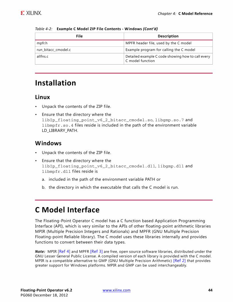
Table 4-2: Example C Model ZIP File Contents - Windows
File Description
floating_point_v6_2_bitacc_cmodel.h Header f ile which defines the C model API
libIp_floating_point_v6_2_bitacc_cmodel.dll Model dynamically linked library
libIp_floating_point_v6_2_bitacc_cmodel.lib Model .lib f ile for compiling
libgmp.dll MPIR library, used by the C model
libgmp.lib MPIR .lib file for compiling
libmpfr.dll MPFR library, used by the C model
libmpfr.lib MPFR .lib file for compiling
gmp.h MPIR header file, used by the C model
Floating-Point Operator v6.2 www.xilinx.com 44PG060 December 18, 2012
Chapter 4: C Model Reference
Installation
Linux• Unpack the contents of the ZIP f ile.
• Ensure that the directory where the libIp_floating_point_v6_2_bitacc_cmodel.so, libgmp.so.7 and libmpfr.so.4 f iles reside is included in the path of the environment variable LD_LIBRARY_PATH.
Windows• Unpack the contents of the ZIP f ile.
• Ensure that the directory where the libIp_floating_point_v6_2_bitacc_cmodel.dll, libgmp.dll and libmpfr.dll f iles reside is
a. included in the path of the environment variable PATH or
b. the directory in which the executable that calls the C model is run.
C Model InterfaceThe Floating-Point Operator C model has a C function based Application Programming Interface (API), which is very similar to the APIs of other floating-point arithmetic libraries MPIR (Multiple Precision Integers and Rationals) and MPFR (GNU Multiple Precision Floating-point Reliable library). The C model uses these libraries internally and provides functions to convert between their data types.
Note: MPIR [Ref 4] and MPFR [Ref 3] are free, open source software libraries, distributed under the GNU Lesser General Public License. A compiled version of each library is provided with the C model. MPIR is a compatible alternative to GMP (GNU Multiple Precision Arithmetic) [Ref 2] that provides greater support for Windows platforms. MPIR and GMP can be used interchangeably.
mpfr.h MPFR header file, used by the C model
run_bitacc_cmodel.c Example program for calling the C model
allfns.c Detailed example C code showing how to call every C model function
Table 4-2: Example C Model ZIP File Contents - Windows (Cont’d)
File Description

Floating-Point Operator v6.2 www.xilinx.com 45PG060 December 18, 2012
Chapter 4: C Model Reference
Two example C f iles, run_bitacc_cmodel.c and allfns.c, are included, that demonstrate how to call the C model. See these f iles for examples of using the interface described in the following sections.
The Application Programming Interface (API) of the C model is defined in the header f ile floating_point_v6_2_bitacc_cmodel.h. The interface consists of data structures and functions as described in the following sections.
Data TypesThe C types defined for the Floating-Point Operator C model are shown in Table 4-3.
xip_fpo_prec_t is used for initializing variables of type xip_fpo_t and xip_fpo_fix_t.
xip_fpo_prec_t and xip_fpo_exp_t are of type long for compatibility with MPFR, not because they need a greater numerical range than provided by int.
The Floating-Point Operator C model functions use xip_fpo_t and xip_fpo_fix_t for input and output variables. Users should use these types for all custom precision floating-point and f ixed-point variables. Defining this type as a one-element array of the
Table 4-3: Floating-Point Operator C Model Data Types
Name Type Description
xip_fpo_prec_t long Precision of mantissa or exponent (bits)
xip_fpo_sign_t int Sign bit of a floating-point number
xip_fpo_exp_t long Exponent of a floating-point number
xip_fpo_t struct[1] Custom precision floating-point number (internally defined as a one-element array of a structure)
xip_fpo_fix_t struct[1] Custom precision fixed-point number (internally defined as a one-element array of a structure)
xip_fpo_ptr struct *Pointer to underlying custom precision floating-point struct. Equivalent to xip_fpo_t but easier to use in certain situations (for example, terminator in xip_fpo_inits2 function).
xip_fpo_fix_ptr struct *Pointer to underlying custom precision f ixed-point struct. Equivalent to xip_fpo_fix_t but easier to use in certain situations (for example, terminator in xip_fpo_fix_inits2 function).
xip_fpo_exc_t int
Bitwise flags which when set indicate exceptions that occurred during an operation:bit 0: underflowbit 1: overflowbit 2: invalid operationbit 3: divide by zerobit 4: operation not supported by Floating-Point Operator v6.2 core (for example, add with different precision operands)bit 5: accumulator input overflowbit 6: accumulator overflow

Floating-Point Operator v6.2 www.xilinx.com 46PG060 December 18, 2012
Chapter 4: C Model Reference
underlying struct means that when a user declares a variable of this type, the memory for the struct members is automatically allocated, and the user can pass the variable as-is to functions with no need to add a * to pass a pointer, and it is automatically passed by reference. This is the same method as used by MPIR [Ref 4] and MPFR [Ref 3].
xip_fpo_t is an IEEE-754 compatible floating-point type, except that signaling NaNs and denormalized numbers are not supported. If a signaling NaN is stored in an xip_fpo_t variable, the value becomes a quiet NaN. Similarly, denormalized numbers are converted to zero (with an underflow exception, if appropriate).
xip_fpo_exc_t is the return value type of most functions.
The C model API also provides versions of its operation functions for single and double precision, using standard C data types float and double respectively. This provides an easy use model for applications that do not require custom precision.
Functions There are several C model functions accessible to the user.
Information Functions
The Floating-Point Operator C model information functions are shown in Table 4-4.
Initialization Functions
The Floating-Point Operator C model initialization functions are shown in Table 4-5. Most functions have variants to handle floating-point and fixed-point variables.
Table 4-4: Floating-Point Operator C Model Information Functions
Name Return Arguments Description
xip_fpo_get_version const char * void Return the Floating-Point Operator C model version, as a null-terminated string. For v6.2 this is “6.2”.
Table 4-5: Floating-Point Operator C Model Initialization Functions
Name Return Arguments Description
xip_fpo_init2 void xip_fpo_t x, xip_fpo_prec_t exp,xip_fpo_prec_t mant
Initialize floating-point variable x, set its exponent precision to exp, its mantissa precision to mant, and its value to NaN.
xip_fpo_fix_init2 void xip_fpo_fix_t x, xip_fpo_prec_t i,xip_fpo_prec_t frac
Initialize f ixed-point variable x, set its integer precision to i, its fraction precision to frac, and its value to zero.

Floating-Point Operator v6.2 www.xilinx.com 47PG060 December 18, 2012
Chapter 4: C Model Reference
xip_fpo_inits2 void xip_fpo_prec_t exp,xip_fpo_prec_t mant,xip_fpo_t x, ...
Initialize all xip_fpo_t variables pointed to by the argument list, set their exponent precision to exp, their mantissa precision to mant, and their value to NaN. The last item in the list must be a null pointer of type xip_fpo_t (or equivalently xip_fpo_ptr).
xip_fpo_fix_inits2 void xip_fpo_prec_t i,xip_fpo_prec_t frac,xip_fpo_fix_t x, ...
Initialize all xip_fpo_fix_t variables pointed to by the argument list, set their integer precision to i, their fraction precision to frac, and their value to zero. The last item in the list must be a null pointer of type xip_fpo_fix_t (or equivalently xip_fpo_fix_ptr).
xip_fpo_clear void xip_fpo_t x Free the memory used by x.
xip_fpo_fix_clear void xip_fpo_fix_t x Free the memory used by x.
xip_fpo_clears void xip_fpo_t x,... Free the memory used by all xip_fpo_t variables pointed to by the argument list. The last item in the list must be a null pointer of type xip_fpo_t (or equivalently xip_fpo_ptr).
xip_fpo_fix_clears void xip_fpo_fix_t x,... Free the memory used by all xip_fpo_fix_t variables pointed to by the argument list. The last item in the list must be a null pointer of type xip_fpo_fix_t (or equivalently xip_fpo_fix_ptr).
xip_fpo_set_prec void xip_fpo_t x, xip_fpo_prec_t exp,xip_fpo_prec_t mant
Reset x to an exponent precision of exp, a mantissa precision of mant, and set its value to NaN. The previous value of x is lost.
xip_fpo_fix_set_prec void xip_fpo_fix_t x, xip_fpo_prec_t i,xip_fpo_prec_t frac
Reset x to an integer precision of i, a fraction precision of frac, and set its value to zero. The previous value of x is lost.
xip_fpo_get_prec_mant xip_fpo_prec_t xip_fpo_t x Return the mantissa precision (in bits) of x.
xip_fpo_get_prec_exp xip_fpo_prec_t xip_fpo_t x Return the exponent precision (in bits) of x.
xip_fpo_fix_get_prec_frac xip_fpo_prec_t xip_fpo_fix_t x Return the fraction precision (in bits) of x.
xip_fpo_fix_get_prec_int xip_fpo_prec_t xip_fpo_fix_t x Return the integer precision (in bits) of x.
Table 4-5: Floating-Point Operator C Model Initialization Functions (Cont’d)
Name Return Arguments Description

Floating-Point Operator v6.2 www.xilinx.com 48PG060 December 18, 2012
Chapter 4: C Model Reference
A floating-point number has a minimum exponent required to support normalization:
If the exponent width specif ied for xip_fpo_init2 or xip_fpo_set_prec for initializing or resetting a floating-point variable is too small, it is internally increased to the minimum permitted width.
A variable should be initialized only once, or be cleared using xip_fpo_clear between initializations. To change the precision of a variable that has already been initialized, use xip_fpo_set_prec.
An example of initializing and clearing floating-point variables is shown:
xip_fpo_t x, y, z;xip_fpo_init2 (x, 11, 53); // double precisionxip_fpo_inits2 (7, 17, y, z, (xip_fpo_ptr) 0); // custom precision// perform operationsxip_fpo_set_prec (8, 24, y); // change to single precision// more operationsxip_fpo_clears (x, y, z, (xip_fpo_ptr) 0);
Assignment Functions
The Floating-Point Operator C model assignment functions are shown in Table 4-6. Most functions have variants to handle both floating-point and f ixed-point variables. Functions are provided for assigning Floating-Point Operator C model variables from MPIR and MPFR variables for ease of use alongside these existing libraries.
minimum exponent width ceil 2 fraction width 3+( )log( ) 1+=

Floating-Point Operator v6.2 www.xilinx.com 49PG060 December 18, 2012
Chapter 4: C Model Reference
Table 4-6: Floating-Point Operator C Model Assignment Functions
Name Return Arguments Description
xip_fpo_set xip_fpo_exc_t xip_fpo_t rop,xip_fpo_t op
Set the value of rop to op.(1)
xip_fpo_fix_set xip_fpo_exc_t xip_fpo_fix_t rop, xip_fpo_fix_t op
xip_fpo_set_ui xip_fpo_exc_t xip_fpo_t rop, unsigned long op
xip_fpo_fix_set_ui xip_fpo_exc_t xip_fpo_fix_t rop, unsigned long op
xip_fpo_set_si xip_fpo_exc_t xip_fpo_t rop, signed long op
xip_fpo_fix_set_si xip_fpo_exc_t xip_fpo_fix_t rop, signed long op
xip_fpo_set_uj xip_fpo_exc_t xip_fpo_t rop, uintmax_t op
xip_fpo_fix_set_uj xip_fpo_exc_t xip_fpo_fix_t rop, uintmax_t op
xip_fpo_set_sj xip_fpo_exc_t xip_fpo_t rop, intmax_t op
xip_fpo_fix_set_sj xip_fpo_exc_t xip_fpo_fix_t rop, intmax_t op
xip_fpo_set_flt xip_fpo_exc_t xip_fpo_t rop, float op
xip_fpo_fix_set_flt xip_fpo_exc_t xip_fpo_fix_t rop, float op
xip_fpo_set_d xip_fpo_exc_t xip_fpo_t rop, double op
xip_fpo_fix_set_d xip_fpo_exc_t xip_fpo_fix_t rop, double op
xip_fpo_set_z xip_fpo_exc_t xip_fpo_t rop,mpz_t op
Set the value of rop to the value of GMP/MPIR integer op.(1)
xip_fpo_fix_set_z xip_fpo_exc_t xip_fpo_fix_t rop,mpz_t op
xip_fpo_set_q xip_fpo_exc_t xip_fpo_t rop,mpq_t op
Set the value of rop to the value of GMP/MPIR rational number op.(1)
xip_fpo_fix_set_q xip_fpo_exc_t xip_fpo_fix_t rop,mpq_t op
xip_fpo_set_f xip_fpo_exc_t xip_fpo_t rop,mpf_t op
Set the value of rop to the value of GMP/MPIR floating-point number op.(1)
xip_fpo_fix_set_f xip_fpo_exc_t xip_fpo_fix_t rop,mpf_t op

Floating-Point Operator v6.2 www.xilinx.com 50PG060 December 18, 2012
Chapter 4: C Model Reference
xip_fpo_set_str and xip_fpo_fix_set_str
The functions xip_fpo_set_str and xip_fpo_fix_set_str take a string argument (actually const char *) and an integer base. They have the same usage as the MPFR function mpfr_set_str.
The base is a value between 2 and 62 or zero. The string is a representation of numeric data to be read and stored in the floating-point variable. The whole string must represent a valid floating-point number.
The form of numeric data is a non-empty sequence of significand digits with an optional decimal point, and an optional exponent consisting of an exponent prefix followed by an
xip_fpo_set_fr xip_fpo_exc_t xip_fpo_t rop,mpfr_t op
Set the value of rop to the value of MPFR floating-point number op.(1)
xip_fpo_fix_set_fr xip_fpo_exc_t xip_fpo_fix_t rop,mpfr_t op
xip_fpo_set_ui_2exp xip_fpo_exc_t xip_fpo_t rop, unsigned long op,xip_fpo_exp_t e
Set the value of rop to op multiplied by two to the power of e.(1)
xip_fpo_set_si_2exp xip_fpo_exc_t xip_fpo_t rop, signed long op,xip_fpo_exp_t e
xip_fpo_set_uj_2exp xip_fpo_exc_t xip_fpo_t rop, uintmax_t op,intmax_t e
xip_fpo_set_sj_2exp xip_fpo_exc_t xip_fpo_t rop, intmax_t op,intmax_te
xip_fpo_set_str xip_fpo_exc_t xip_fpo_t rop,const char *s,int base
Set the value of rop to the string in s which is in the base base. See xip_fpo_set_str and xip_fpo_fix_set_str for details.(1)
xip_fpo_fix_set_str xip_fpo_exc_t xip_fpo_fix_t rop,const char *s,int base
xip_fpo_set_nan void xip_fpo_t x Set the value of x to NaN.
xip_fpo_set_inf void xip_fpo_t x,int sign
Set the value of x to plus infinity if sign is non-negative, minus infinity otherwise.
xip_fpo_set_zero void xip_fpo_t x,int sign
Set the value of x to plus zero if sign is non-negative, minus zero otherwise.
Notes: 1. Any exceptions that occur are signaled in the return value.
When assigning to a f ixed-point variable, if overflow occurs, the result is saturated and the return value is the largest representable f ixed-point number of the correct sign. Converting a NaN returns the most negative representable f ixed-point number and the invalid operation exception is signaled in the return value.
Table 4-6: Floating-Point Operator C Model Assignment Functions (Cont’d)
Name Return Arguments Description

Floating-Point Operator v6.2 www.xilinx.com 51PG060 December 18, 2012
Chapter 4: C Model Reference
optional sign and a non-empty sequence of decimal digits. A significand digit is either a decimal digit or a Latin letter (62 possible characters), with A = 10, B = 11, ..., Z = 35; case is ignored in bases less or equal to 36, in bases larger than 36, a = 36, b = 37, ..., z = 61. The value of a signif icant digit must be strictly less than the base. The decimal point can be either the one defined by the current locale or the period (the f irst one is accepted for consistency with the C standard and the practice, the second one is accepted to allow the programmer to provide numbers from strings in a way that does not depend on the current locale). The exponent prefix can be e or E for bases up to 10, or @ in any base; it indicates a multiplication by a power of the base. In bases 2 and 16, the exponent prefix can also be p or P, in which case the exponent, called binary exponent, indicates a multiplication by a power of 2 instead of the base (there is a difference only for base 16); in base 16 for example 1p2 represents 4 whereas 1@2 represents 256.
If the argument base is 0, then the base is automatically detected as follows. If the signif icand starts with 0b or 0B, base 2 is assumed. If the signif icand starts with 0x or 0X, base 16 is assumed. Otherwise base 10 is assumed.
Note: The exponent (if present) must contain at least a digit. Otherwise, the possible exponent prefix and sign are not part of the number (which ends with the signif icand). Similarly, if 0b, 0B, 0x or 0X is not followed by a binary/hexadecimal digit, then the subject sequence stops at the character 0, thus 0 is read.
Special data (for infinities and NaN) can be @inf@ or @nan@(n-char-sequence-opt), and if base <= 16, it can also be infinity, inf, nan or nan(n-char-sequence-opt), all case insensitive. A n-char-sequence-opt is a possibly empty string containing only digits, Latin letters and the underscore (0, 1, 2, ..., 9, a, b, ..., z, A, B, ..., Z, _).
Note: There is an optional sign for all data, even NaN. For example, -@nAn@(This_Is_Not_17) is a valid representation for NaN in base 17.
If the whole string cannot be parsed into a floating-point or f ixed-point number, then an invalid operation exception is signaled. In this case, rop might have changed. Overflow or underflow can occur if the string is parsed to a floating-point or f ixed-point number that is too large or too small to represent in the floating-point or f ixed-point precision of the variable.
Conversion Functions
The Floating-Point Operator C model conversion functions are shown in Table 4-7. Most functions have variants to handle both floating-point and f ixed-point variables.
Functions that convert to a standard C data type return the converted result as that data type. Any exceptions that occur are ignored. Functions that convert to GMP or MPFR data types place the result in the f irst argument and return exception flags, as with most Floating-Point Operator C model functions.
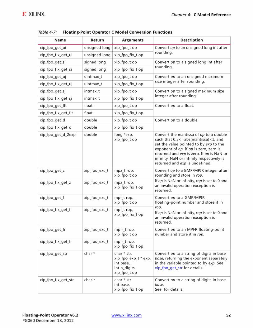
Floating-Point Operator v6.2 www.xilinx.com 52PG060 December 18, 2012
Chapter 4: C Model Reference
Table 4-7: Floating-Point Operator C Model Conversion Functions
Name Return Arguments Description
xip_fpo_get_ui unsigned long xip_fpo_t op Convert op to an unsigned long int after rounding.xip_fpo_fix_get_ui unsigned long xip_fpo_fix_t op
xip_fpo_get_si signed long xip_fpo_t op Convert op to a signed long int after rounding.xip_fpo_fix_get_si signed long xip_fpo_fix_t op
xip_fpo_get_uj uintmax_t xip_fpo_t op Convert op to an unsigned maximum size integer after rounding.xip_fpo_fix_get_uj uintmax_t xip_fpo_fix_t op
xip_fpo_get_sj intmax_t xip_fpo_t op Convert op to a signed maximum size integer after rounding.xip_fpo_fix_get_sj intmax_t xip_fpo_fix_t op
xip_fpo_get_flt float xip_fpo_t op Convert op to a float.
xip_fpo_fix_get_flt float xip_fpo_fix_t op
xip_fpo_get_d double xip_fpo_t op Convert op to a double.
xip_fpo_fix_get_d double xip_fpo_fix_t op
xip_fpo_get_d_2exp double long *exp,xip_fpo_t op
Convert the mantissa of op to a double such that 0.5<=abs(mantissa)<1, and set the value pointed to by exp to the exponent of op. If op is zero, zero is returned and exp is zero. If op is NaN or infinity, NaN or infinity respectively is returned and exp is undefined.
xip_fpo_get_z xip_fpo_exc_t mpz_t rop,xip_fpo_t op
Convert op to a GMP/MPIR integer after rounding and store in rop.If op is NaN or infinity, rop is set to 0 and an invalid operation exception is returned.
xip_fpo_fix_get_z xip_fpo_exc_t mpz_t rop,xip_fpo_fix_t op
xip_fpo_get_f xip_fpo_exc_t mpf_t rop,xip_fpo_t op
Convert op to a GMP/MPIR floating-point number and store it in rop.If op is NaN or infinity, rop is set to 0 and an invalid operation exception is returned.
xip_fpo_fix_get_f xip_fpo_exc_t mpf_t rop,xip_fpo_fix_t op
xip_fpo_get_fr xip_fpo_exc_t mpfr_t rop,xip_fpo_t op
Convert op to an MPFR floating-point number and store it in rop.
xip_fpo_fix_get_fr xip_fpo_exc_t mpfr_t rop,xip_fpo_fix_t op
xip_fpo_get_str char * char * str,xip_fpo_exp_t * exp,int base,int n_digits,xip_fpo_t op
Convert op to a string of digits in base base, returning the exponent separately in the variable pointed to by exp. See xip_fpo_get_str for details.
xip_fpo_fix_get_str char * char * str,int base,xip_fpo_fix_t op
Convert op to a string of digits in base base. See for details.

Floating-Point Operator v6.2 www.xilinx.com 53PG060 December 18, 2012
Chapter 4: C Model Reference
xip_fpo_get_str
The function xip_fpo_get_str has the same usage as the MPFR function mpfr_get_str. n_digits is either zero or the number of significant digits output in the string; in the latter case, n_digits must be greater or equal to 2. The base can vary from 2 to 62. If the input number is an ordinary number, the exponent is written through the pointer exp (for input 0, the exponent is set to 0).
The generated string is in the base specified by base. Each string character is either a decimal digit or a Latin letter (62 possible characters). For base in the range 2 to 36, decimal digits and lower case letters are used, with a = 10, b = 11, … z = 35. For base in the range 37 to 62, digits, upper case, and lower case letters are used, with A = 10, B = 11, ..., Z = 35, a = 36, b = 37, ..., z = 61.
The generated string is a fraction, with an implicit radix point immediately to the left of the f irst digit. For example, the number -3.1416 would be returned as "-31416" in the string and 1 written at exp. The value is rounded to provide n_digits of output, using round to nearest even: if op is exactly in the middle of two consecutive possible outputs, the one with an even signif icand is chosen, where both significands are considered with the exponent of op. For an odd base, this might not correspond to an even last digit: for example with 2 digits in base 7, (14) and a half is rounded to (15) which is 12 in decimal, (16) and a half is rounded to (20) which is 14 in decimal, and (26) and a half is rounded to (26) which is 20 in decimal.
If n_digits is zero, the number of digits of the significand is chosen large enough so that re-reading the printed value with the same precision recovers the original value of op. More precisely, in most cases, the chosen precision of str is the minimal precision m depending only on p = PREC(op) and b that satisf ies the above property, that is, m = 1 + ceil(p*log(2)/log(b)), with p replaced by p-1 if b is a power of 2.
xip_fpo_free_str void char * str Free a string allocated by xip_fpo_get_str or xip_fpo_fix_get_str.
xip_fpo_fix_free_str void char * str A synonym for xip_fpo_free_str.
xip_fpo_sizeinbase int xip_fpo_t op,int base
Return the size of op measured in number of digits in the given base. base can vary from 2 to 62. The sign of op is ignored.Returns -1 if an error occurs.Use to determine the space required when converting op to a string using xip_fpo_get_str or xip_fpo_fix_get_str.
xip_fpo_fix_sizeinbase int xip_fpo_fix_t op,int base
Table 4-7: Floating-Point Operator C Model Conversion Functions (Cont’d)
Name Return Arguments Description

Floating-Point Operator v6.2 www.xilinx.com 54PG060 December 18, 2012
Chapter 4: C Model Reference
If str is a null pointer, space for the significand is allocated using the GMP/MPIR current allocation function which is malloc() by default, and a pointer to the string is returned. To free the memory used by the returned string, you must use xip_fpo_free_str.
If str is not a null pointer, it should point to a block of storage large enough for the signif icand, that is, at least max(n_digits + 2, 7) if n_digits > 0, or xip_fpo_sizeinbase (op, base) + 2 otherwise. The extra two bytes are for a possible minus sign, and for the terminating null character, and the value 7 accounts for -@Inf@ plus the terminating null character.
A pointer to the string is returned, unless there is an error, in which case a null pointer is returned.
xip_fpo_fix_get_str
The function xip_fpo_fix_get_str has the same usage as the GMP/MPIR function mpz_get_str. The base can vary from 2 to 62.
The generated string is in the base specified by base. Each string character is either a decimal digit or a Latin letter (62 possible characters). For base in the range 2 to 36, decimal digits and lower case letters are used, with a = 10, b = 11, … z = 35. For base in the range 37 to 62, digits, upper case, and lower case letters are used, with A = 10, B = 11, ..., Z = 35, a = 36, b = 37, ..., z = 61.
The generated string is either an integer value with no radix point, or a fraction with an explicit radix point. All signif icant digits are returned, but no leading or trailing zeros are returned. No rounding is carried out.
If str is a null pointer, space for the significand is allocated using the current allocation function, and a pointer to the string is returned. To free the memory used by the returned string, you must use xip_fpo_fix_free_str.
If str is not a null pointer, it should point to a block of storage large enough for the result, that being xip_fpo_fix_sizeinbase (op, base) + 2. The extra two bytes are for a possible minus sign, and the terminating null character.
Operation Functions
The Floating-Point Operator C model functions that model operations of the core are shown in Table 4-8. In addition to functions using xip_fpo_t and xip_fpo_fix_t type arguments to provide custom precision, alternative versions of functions using standard C data types float and double are also provided to make it easy for customers who do not need custom precision. For f ixed to float and float to fixed functions, float and double to and from int are provided. For float to float functions, all combinations of float and double are provided: where these data types are the same, the function provides a means to condition numbers (convert signaling NaNs to quiet NaNs, convert denormalized numbers to zero).

Floating-Point Operator v6.2 www.xilinx.com 55PG060 December 18, 2012
Chapter 4: C Model Reference
Table 4-8: Floating-Point Operator C Model Operation Functions
Name Return Arguments Description
xip_fpo_add xip_fpo_exc_t xip_fpo_t rop,xip_fpo_t op1,xip_fpo_t op2
Set rop = op1 + op2. rop, op1 and op2 must have identical precisions, otherwise an operation not supported exception is returned.
xip_fpo_add_flt xip_fpo_exc_t float * rop,float op1,float op2
Set rop = op1 + op2. Single precision version.
xip_fpo_add_d xip_fpo_exc_t double * rop,double op1,double op2
Set rop = op1 + op2. Double precision version.
xip_fpo_sub xip_fpo_exc_t xip_fpo_t rop,xip_fpo_t op1,xip_fpo_t op2
Set rop = op1 - op2. rop, op1 and op2 must have identical precisions, otherwise an operation not supported exception is returned.
xip_fpo_sub_flt xip_fpo_exc_t float * rop,float op1,float op2
Set rop = op1 - op2. Single precision version.
xip_fpo_sub_d xip_fpo_exc_t double * rop,double op1,double op2
Set rop = op1 - op2. Double precision version.
xip_fpo_accum_create_state xil_fpo_accum_state * int exponent_width,int fractional_width,int accumulator_msb,int input_msb,int accumulator_lsb
Returns a pointer to a xil_fpo_accum_state object. This is needed by all the other accumulator functions.
xip_fpo_accum_reset_state void xil_fpo_accum_state *state Resets the xil_fpo_accum_state object. Call this to start a new accumulation. Has the effect of clearing the accumulator and resetting the exception flags.
xip_fpo_accum_destroy_state void xil_fpo_accum_state *state Destroys the xil_fpo_accum_state object and frees any memory allocated. The xil_fpo_accum_state object pointer can no longer be used.

Floating-Point Operator v6.2 www.xilinx.com 56PG060 December 18, 2012
Chapter 4: C Model Reference
xip_fpo_accum_sample xip_fpo_exc_t xip_fpo_t rop,xip_fpo_t op,bool subtract,xil_fpo_accum_state *state
Add/Subtract op to/from the accumulator and return the result. Adds when subtract = false; Subtracts when subtract = true.rop and op must have identical precisions, otherwise an operation not supported exception is returned.
xip_fpo_accum_sample_flt xip_fpo_exc_t float * rop,float op,bool subtract,xil_fpo_accum_state *state
Add/Subtract op to/from the accumulator and return the result. Single precision version.Adds when subtract = false; Subtracts when subtract = true.
xip_fpo_accum_sample_d xip_fpo_exc_t double * rop,double op,bool subtract,xil_fpo_accum_state *state
Add/Subtract op to/from the accumulator and return the result. Double precision version.Adds when subtract = false; Subtracts when subtract = true.
xip_fpo_mul xip_fpo_exc_t xip_fpo_t rop,xip_fpo_t op1,xip_fpo_t op2
Set rop = op1 × op2. rop, op1 and op2 must have identical precisions, otherwise an operation not supported exception is returned.
xip_fpo_mul_flt xip_fpo_exc_t float * rop,float op1,float op2
Set rop = op1 × op2. Single precision version.
xip_fpo_mul_d xip_fpo_exc_t double * rop,double op1,double op2
Set rop = op1 × op2. Double precision version.
xip_fpo_fma xip_fpo_exc_t xip_fpo_t rop,xip_fpo_t op1,xip_fpo_t op2,xip_fpo_t op3
Set rop = (op1 x op2) + op3. rop, op1, op2, and op3 must have identical precisions, otherwise an operation not supported exception is returned.
xip_fpo_fma_flt xip_fpo_exc_t float * rop,float op1,float op2,float op3
Set rop = (op1 x op2) + op3. Single precision version.
Table 4-8: Floating-Point Operator C Model Operation Functions (Cont’d)
Name Return Arguments Description

Floating-Point Operator v6.2 www.xilinx.com 57PG060 December 18, 2012
Chapter 4: C Model Reference
xip_fpo_fma_d xip_fpo_exc_t double * rop,double op1,double op2,double op3
Set rop = (op1 x op2) + op3. Double precision version.
xip_fpo_fms xip_fpo_exc_t xip_fpo_t rop, xip_fpo_t op1, xip_fpo_t op2, xip_fpo_t op3
Set rop = (op1 x op2) - op3. rop, op1, op2, and op3 must have identical precisions, otherwise an operation not supported exception is returned.
xip_fpo_fms_flt xip_fpo_exc_t float * rop, float op1, float op2, float op3
Set rop = (op1 x op2) - op3. Single precision version.
xip_fpo_fms_d xip_fpo_exc_t double * rop,double op1,double op2,double op3
Set rop = (op1 x op2) - op3. Double precision version.
xip_fpo_div xip_fpo_exc_t xip_fpo_t rop,xip_fpo_t op1,xip_fpo_t op2
Set rop = op1/op2. rop, op1 and op2 must have identical precisions, otherwise an operation not supported exception is returned.
xip_fpo_div_flt xip_fpo_exc_t float * rop,float op1,float op2
Set rop = op1 / op2. Single precision version.
xip_fpo_div_d xip_fpo_exc_t double * rop,double op1,double op2
Set rop = op1/op2. Double precision version.
xip_fpo_rec(1) xip_fpo_exc_t xip_fpo_t rop,xip_fpo_t op
Set rop = 1/op. rop and op must have identical precisions, otherwise an operation not supported exception is returned.
xip_fpo_rec_flt xip_fpo_exc_t float * rop,float op
Set rop = 1/op. Single precision version.
xip_fpo_rec_d xip_fpo_exc_t double * rop,double op
Set rop = 1/op. Double precision version.
xip_fpo_sqrt xip_fpo_exc_t xip_fpo_t rop,xip_fpo_t op
Set rop = square root of op. rop and op must have identical precisions, otherwise an operation not supported exception is returned.
xip_fpo_sqrt_flt xip_fpo_exc_t float * rop,float op
Set rop = square root of op. Single precision version.
Table 4-8: Floating-Point Operator C Model Operation Functions (Cont’d)
Name Return Arguments Description

Floating-Point Operator v6.2 www.xilinx.com 58PG060 December 18, 2012
Chapter 4: C Model Reference
xip_fpo_sqrt_d xip_fpo_exc_t double * rop,double op
Set rop = square root of op. Double precision version.
xip_fpo_recsqrt(1) xip_fpo_exc_t xip_fpo_t rop,xip_fpo_t op
Set rop = 1/(square root of op). rop and op must have identical precisions, otherwise an operation not supported exception is returned.
xip_fpo_recsqrt_flt xip_fpo_exc_t float * rop,float op
Set rop = 1/(square root of op). Single precision version.
xip_fpo_recsqrt_d xip_fpo_exc_t double * rop,double op
Set rop = 1/(square root of op). Double precision version.
xip_fpo_abs xip_fpo_exc_t xip_fpo_t rop,xip_fpo_t op
Set rop = |op|. rop and op must have identical precisions, otherwise an operation not supported exception is returned.
xip_fpo_abs_flt xip_fpo_exc_t float * rop,float op
Set rop = |op|. Single precision version.
xip_fpo_abs_d xip_fpo_exc_t double * rop,double op
Set rop = |op|. Double precision version.
xip_fpo_log(1) xip_fpo_exc_t xip_fpo_t rop,xip_fpo_t op
Set rop = natural logarithm of op. rop and op must have identical precisions, otherwise an operation not supported exception is returned.
xip_fpo_log_flt xip_fpo_exc_t float * rop,float op
Set rop = natural logarithm of op. Single precision version.
xip_fpo_log_d xip_fpo_exc_t double * rop,double op
Set rop = natural logarithm of op. Double precision version.
xip_fpo_exp(1) xip_fpo_exc_t xip_fpo_t rop,xip_fpo_t op
Set rop = exponential of op. rop and op must have identical precisions, otherwise an operation not supported exception is returned.
xip_fpo_exp_flt xip_fpo_exc_t float * rop,float op
Set rop = exponential of op. Single precision version.
xip_fpo_exp_d xip_fpo_exc_t double * rop, double op
Set rop = exponential of op. Double precision version.
Table 4-8: Floating-Point Operator C Model Operation Functions (Cont’d)
Name Return Arguments Description

Floating-Point Operator v6.2 www.xilinx.com 59PG060 December 18, 2012
Chapter 4: C Model Reference
xip_fpo_exp_array(1) int xip_fpo_t * rop,xip_fpo_t * op,xip_fpo_exc_t *exceptions,unsigned long long num_values
Process an array of values This provides a signif icant performance improvement over calling xip_fpo_exp for individual values. Set rop[i] = exponential of op[i]. All rop[] and op[] entries must have identical precisions, otherwise an operation not supported exception is returned. The return value indicates the last array element processed (either successfully or with an operation not supported exception)
xip_fpo_exp_flt_array void float * rop, float * op,xip_fpo_exc_t exceptions*,unsigned long long num_values
Process an array of values. This provides a signif icant performance improvement over calling xip_fpo_exp_flt for individual values. Set rop[i] = exponential of op[i]. Single precision version.
xip_fpo_exp_d_array void double * rop,double * op,xip_fpo_exc_t * exceptions,unsigned long long num_values
Process an array of values. This provides a signif icant performance improvement over calling xip_fpo_exp_d for individual values. Set rop[i] = exponential of op[i]. Double precision version.
xip_fpo_unordered xip_fpo_exc_t int * res,xip_fpo_t op1,xip_fpo_t op2
Set res = 1 if op1 or op2 is a NaN, 0 otherwise. op1 and op2 must have identical precisions, otherwise an operation not supported exception is returned.
xip_fpo_unordered_flt xip_fpo_exc_t int * res,float op1,float op2
Set res = 1 if op1 or op2 is a NaN, 0 otherwise. Single precision version.
xip_fpo_unordered_d xip_fpo_exc_t int * res,double op1,double op2
Set res = 1 if op1 or op2 is a NaN, 0 otherwise. Double precision version.
Table 4-8: Floating-Point Operator C Model Operation Functions (Cont’d)
Name Return Arguments Description

Floating-Point Operator v6.2 www.xilinx.com 60PG060 December 18, 2012
Chapter 4: C Model Reference
xip_fpo_equal xip_fpo_exc_t int * res,xip_fpo_t op1,xip_fpo_t op2
Set res = 1 if op1 = op2, 0 otherwise. op1 and op2 must have identical precisions, otherwise an operation not supported exception is returned.
xip_fpo_equal_flt xip_fpo_exc_t int * res,float op1,float op2
Set res = 1 if op1 = op2, 0 otherwise. Single precision version.
xip_fpo_equal_d xip_fpo_exc_t int * res,double op1,double op2
Set res = 1 if op1 = op2, 0 otherwise. Double precision version.
xip_fpo_less xip_fpo_exc_t int * res,xip_fpo_t op1,xip_fpo_t op2
Set res = 1 if op1 < op2, 0 otherwise. op1 and op2 must have identical precisions, otherwise an operation not supported exception is returned.
xip_fpo_less_flt xip_fpo_exc_t int * res,float op1,float op2
Set res = 1 if op1 < op2, 0 otherwise. Single precision version.
xip_fpo_less_d xip_fpo_exc_t int * res,double op1,double op2
Set res = 1 if op1 < op2, 0 otherwise. Double precision version.
xip_fpo_lessequal xip_fpo_exc_t int * res,xip_fpo_t op1,xip_fpo_t op2
Set res = 1 if op1 <= op2, 0 otherwise. op1 and op2 must have identical precisions, otherwise an operation not supported exception is returned.
xip_fpo_lessequal_flt xip_fpo_exc_t int * res,float op1,float op2
Set res = 1 if op1 <= op2, 0 otherwise. Single precision version.
xip_fpo_lessequal_d xip_fpo_exc_t int * res,double op1,double op2
Set res = 1 if op1 <= op2, 0 otherwise. Double precision version.
xip_fpo_greater xip_fpo_exc_t int * res,xip_fpo_t op1,xip_fpo_t op2
Set res = 1 if op1 > op2, 0 otherwise. op1 and op2 must have identical precisions, otherwise an operation not supported exception is returned.
xip_fpo_greater_flt xip_fpo_exc_t int * res,float op1,float op2
Set res = 1 if op1 > op2, 0 otherwise. Single precision version.
Table 4-8: Floating-Point Operator C Model Operation Functions (Cont’d)
Name Return Arguments Description

Floating-Point Operator v6.2 www.xilinx.com 61PG060 December 18, 2012
Chapter 4: C Model Reference
xip_fpo_greater_d xip_fpo_exc_t int * res,double op1,double op2
Set res = 1 if op1 > op2, 0 otherwise. Double precision version.
xip_fpo_greaterequal xip_fpo_exc_t int * res,xip_fpo_t op1,xip_fpo_t op2
Set res = 1 if op1 >= op2, 0 otherwise. op1 and op2 must have identical precisions, otherwise an operation not supported exception is returned.
xip_fpo_greaterequal_flt xip_fpo_exc_t int * res,float op1,float op2
Set res = 1 if op1 >= op2, 0 otherwise. Single precision version.
xip_fpo_greaterequal_d xip_fpo_exc_t int * res,double op1,double op2
Set res = 1 if op1 >= op2, 0 otherwise. Double precision version.
xip_fpo_notequal xip_fpo_exc_t int * res,xip_fpo_t op1,xip_fpo_t op2
Set res = 1 if op1 <> op2 or either op1 or op2 are NaN, 0 otherwise. op1 and op2 must have identical precisions, otherwise an operation not supported exception is returned.
xip_fpo_notequal_flt xip_fpo_exc_t int * res,float op1,float op2
Set res = 1 if op1 <> op2 or either op1 or op2 are NaN, 0 otherwise. Single precision version.
xip_fpo_notequal_d xip_fpo_exc_t int * res,double op1,double op2
Set res = 1 if op1 <> op2 or either op1 or op2 are NaN, 0 otherwise. Double precision version.
xip_fpo_condcode xip_fpo_exc_t int * res,xip_fpo_t op1,xip_fpo_t op2
Compare op1 and op2, and set the least significant 4 bits of res to the resulting condition code. See Table 4-9 for the condition code encoding. op1 and op2 must have identical precisions, otherwise an operation not supported exception is returned.
xip_fpo_condcode_flt xip_fpo_exc_t int * res,float op1,float op2
Compare op1 and op2, and set the least significant 4 bits of res to the resulting condition code. See Table 4-9 for the condition code encoding. Single precision version.
Table 4-8: Floating-Point Operator C Model Operation Functions (Cont’d)
Name Return Arguments Description

Floating-Point Operator v6.2 www.xilinx.com 62PG060 December 18, 2012
Chapter 4: C Model Reference
xip_fpo_condcode_d xip_fpo_exc_t int * res,double op1,double op2
Compare op1 and op2, and set the least significant 4 bits of res to the resulting condition code. See Table 4-9 for the condition code encoding. Double precision version.
xip_fpo_flttofix xip_fpo_exc_t xip_fpo_fix_t rop,xip_fpo_t op
Set rop = op, rounding as required. rop and op must have compatible precisions (see xip_fpo_flttofix and xip_fpo_fixtoflt), otherwise an operation not supported exception is returned.
xip_fpo_flttofix_int_flt xip_fpo_exc_t int * rop,float op
Set rop = op, rounding as required. Single precision to integer version.
xip_fpo_flttofix_int_d xip_fpo_exc_t int * rop,double op
Set rop = op, rounding as required. Double precision to integer version.
xip_fpo_fixtoflt xip_fpo_exc_t xip_fpo_t rop,xip_fpo_fix_t op
Set rop = op, rounding as required. rop and op must have compatible precisions (see xip_fpo_flttofix and xip_fpo_fixtoflt), otherwise an operation not supported exception is returned.
xip_fpo_fixtoflt_flt_int xip_fpo_exc_t float * rop,int op
Set rop = op, rounding as required. Integer to single precision version.
xip_fpo_fixtoflt_d_int xip_fpo_exc_t double * rop,int op
Set rop = op, rounding as required. Integer to double precision version.
xip_fpo_flttoflt xip_fpo_exc_t xip_fpo_t rop,xip_fpo_t op
Set rop = op, rounding as required. rop and op can have different precisions.
xip_fpo_flttoflt_flt_flt xip_fpo_exc_t float * rop,float op
Set rop = op, rounding as required. Single to single precision version (for conditioning numbers).
xip_fpo_flttoflt_flt_d xip_fpo_exc_t float * rop,double op
Set rop = op, rounding as required. Double to single precision version.
xip_fpo_flttoflt_d_flt xip_fpo_exc_t double * rop,float op
Set rop = op, rounding as required. Single to double precision version.
Table 4-8: Floating-Point Operator C Model Operation Functions (Cont’d)
Name Return Arguments Description
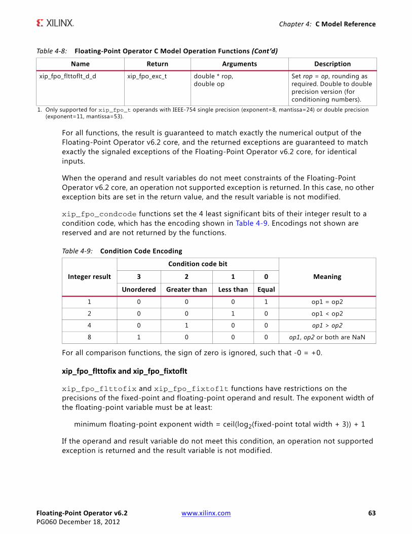
Floating-Point Operator v6.2 www.xilinx.com 63PG060 December 18, 2012
Chapter 4: C Model Reference
For all functions, the result is guaranteed to match exactly the numerical output of the Floating-Point Operator v6.2 core, and the returned exceptions are guaranteed to match exactly the signaled exceptions of the Floating-Point Operator v6.2 core, for identical inputs.
When the operand and result variables do not meet constraints of the Floating-Point Operator v6.2 core, an operation not supported exception is returned. In this case, no other exception bits are set in the return value, and the result variable is not modif ied.
xip_fpo_condcode functions set the 4 least signif icant bits of their integer result to a condition code, which has the encoding shown in Table 4-9. Encodings not shown are reserved and are not returned by the functions.
For all comparison functions, the sign of zero is ignored, such that -0 = +0.
xip_fpo_flttofix and xip_fpo_fixtoflt
xip_fpo_flttofix and xip_fpo_fixtoflt functions have restrictions on the precisions of the fixed-point and floating-point operand and result. The exponent width of the floating-point variable must be at least:
minimum floating-point exponent width = ceil(log2(fixed-point total width + 3)) + 1
If the operand and result variable do not meet this condition, an operation not supported exception is returned and the result variable is not modif ied.
xip_fpo_flttoflt_d_d xip_fpo_exc_t double * rop,double op
Set rop = op, rounding as required. Double to double precision version (for conditioning numbers).
1. Only supported for xip_fpo_t operands with IEEE-754 single precision (exponent=8, mantissa=24) or double precision (exponent=11, mantissa=53).
Table 4-8: Floating-Point Operator C Model Operation Functions (Cont’d)
Name Return Arguments Description
Table 4-9: Condition Code Encoding
Integer result
Condition code bit
Meaning3 2 1 0
Unordered Greater than Less than Equal
1 0 0 0 1 op1 = op2
2 0 0 1 0 op1 < op2
4 0 1 0 0 op1 > op2
8 1 0 0 0 op1, op2 or both are NaN

Floating-Point Operator v6.2 www.xilinx.com 64PG060 December 18, 2012
Chapter 4: C Model Reference
CompilingCompilation of user code requires access to the floating_point_v6_2_bitacc_cmodel.h header file and the header f iles of the MPIR and MPFR dependent libraries, gmp.h and mpfr.h. The header f iles should be copied to a location where they are available to the compiler. Depending on the location chosen, the include search path of the compiler might need to be modif ied.
The floating_point_v6_2_bitacc_cmodel.h header f ile must be included f irst, because it defines some symbols that are used in the MPIR and MPFR header f iles. The floating_point_v6_2_bitacc_cmodel.h header file includes the MPIR and MPFR header f iles, so these do not need to be explicitly included in source code that uses the C model. When compiling on Windows, the symbol NT must be defined, either by a compiler option, or in user source code before the floating_point_v6_2_bitacc_cmodel.h header f ile is included.
LinkingTo use the C model the user executable must be linked against the correct libraries for the target platform.
Note: The C model uses MPIR and MPFR libraries. It is also possible to use GMP or MPIR, and MPFR libraries from other sources, for example, compiled from source code. For details, see Dependent Libraries.
Linux The executable must be linked against the following shared object libraries:
• libgmp.so.7
• libmpfr.so.4
• libIp_floating_point_v6_2_bitacc_cmodel.so
Using GCC, linking is typically achieved by adding the following command line options:
-L. -lgmp -lmpfr -lIp_floating_point_v6_2_bitacc_cmodel
This assumes the shared object libraries are in the current directory. If this is not the case, the -L. option should be changed to specify the library search path to use.
Using GCC, the provided example program run_bitacc_cmodel.c can be compiled and linked using the following command:

Floating-Point Operator v6.2 www.xilinx.com 65PG060 December 18, 2012
Chapter 4: C Model Reference
gcc run_bitacc_cmodel.c -o run_bitacc_cmodel -I. -L. -lgmp -lmpfr -lIp_floating_point_v6_2_bitacc_cmodel
WindowsThe executable must be linked against the following dynamic link libraries:
• libgmp.dll
• libmpfr.dll
• libIp_floating_point_v6_2_bitacc_cmodel.dll
Depending on the compiler, the import libraries might also be required:
• libgmp.lib
• libmpfr.lib
• libIp_floating_point_v6_2_bitacc_cmodel.lib
Using Microsoft Visual Studio, linking is typically achieved by adding the import libraries to the Additional Dependencies entry under the Linker section of Project Properties.
Dependent LibrariesThe C model uses MPIR and MPFR libraries. They are governed by the GNU Lesser General Public License. You can obtain source code for the MPIR and MPFR libraries from www.xilinx.com/guest_resources/gnu/. Pre-compiled MPIR and MPFR libraries are provided with the C model, using the following versions of the libraries:
• MPIR 2.2.1
• MPFR 3.0.1
As MPIR is a compatible alternative to GMP, the GMP library can be used in place of MPIR. It is possible to use GMP or MPIR and MPFR libraries from other sources, for example, compiled from source code.
GMP and MPIR in particular, and MPFR to a lesser extent, contain many low level optimizations for specif ic processors. The libraries provided are compiled for a generic processor on each platform, using no optimized processor-specific code. These libraries work on any processor, but run more slowly than libraries compiled to use optimized processor-specific code. For the fastest performance, compile libraries from source on the machine on which you run the executables.
Source code and compilation scripts are provided for the versions of MPIR and MPFR that were used to compile the provided libraries. Source code and compilation scripts for any
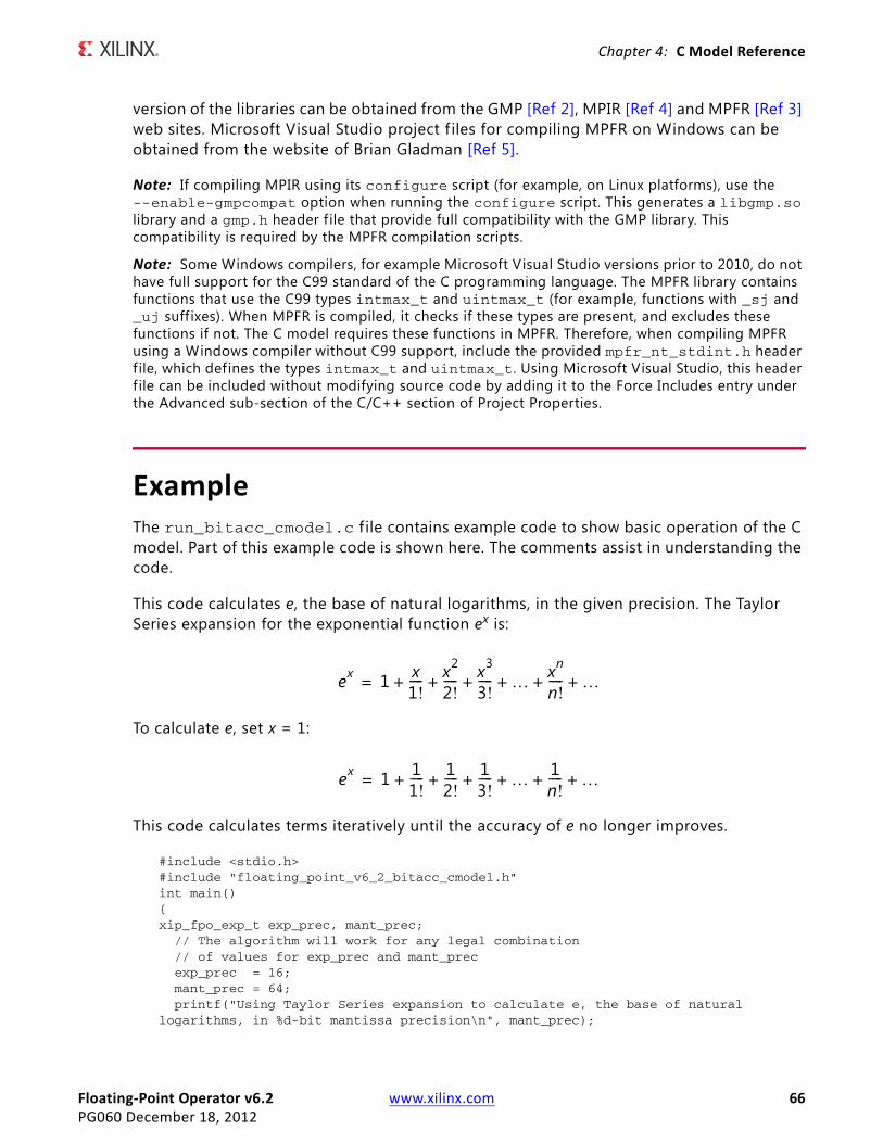
Floating-Point Operator v6.2 www.xilinx.com 66PG060 December 18, 2012
Chapter 4: C Model Reference
version of the libraries can be obtained from the GMP [Ref 2], MPIR [Ref 4] and MPFR [Ref 3] web sites. Microsoft Visual Studio project f iles for compiling MPFR on Windows can be obtained from the website of Brian Gladman [Ref 5].
Note: If compiling MPIR using its configure script (for example, on Linux platforms), use the --enable-gmpcompat option when running the configure script. This generates a libgmp.so library and a gmp.h header f ile that provide full compatibility with the GMP library. This compatibility is required by the MPFR compilation scripts.
Note: Some Windows compilers, for example Microsoft Visual Studio versions prior to 2010, do not have full support for the C99 standard of the C programming language. The MPFR library contains functions that use the C99 types intmax_t and uintmax_t (for example, functions with _sj and _uj suff ixes). When MPFR is compiled, it checks if these types are present, and excludes these functions if not. The C model requires these functions in MPFR. Therefore, when compiling MPFR using a Windows compiler without C99 support, include the provided mpfr_nt_stdint.h header f ile, which defines the types intmax_t and uintmax_t. Using Microsoft Visual Studio, this header f ile can be included without modifying source code by adding it to the Force Includes entry under the Advanced sub-section of the C/C++ section of Project Properties.
ExampleThe run_bitacc_cmodel.c f ile contains example code to show basic operation of the C model. Part of this example code is shown here. The comments assist in understanding the code.
This code calculates e, the base of natural logarithms, in the given precision. The Taylor Series expansion for the exponential function ex is:
To calculate e, set x = 1:
This code calculates terms iteratively until the accuracy of e no longer improves.
#include <stdio.h>#include "floating_point_v6_2_bitacc_cmodel.h"int main(){xip_fpo_exp_t exp_prec, mant_prec; // The algorithm will work for any legal combination // of values for exp_prec and mant_prec exp_prec = 16; mant_prec = 64; printf("Using Taylor Series expansion to calculate e, the base of natural logarithms, in %d-bit mantissa precision\n", mant_prec);
ex 1 x1!---- x2
2!---- x3
3!---- … xn
n!---- …+ + + + + +=
ex 1 11!---- 1
2!---- 1
3!---- … 1
n!---- …+ + + + + +=
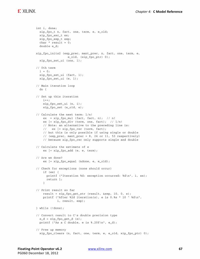
Floating-Point Operator v6.2 www.xilinx.com 67PG060 December 18, 2012
Chapter 4: C Model Reference
int i, done; xip_fpo_t n, fact, one, term, e, e_old; xip_fpo_exc_t ex; xip_fpo_exp_t exp; char * result = 0; double e_d;
xip_fpo_inits2 (exp_prec, mant_prec, n, fact, one, term, e, e_old, (xip_fpo_ptr) 0); xip_fpo_set_ui (one, 1);
// 0th term i = 0; xip_fpo_set_ui (fact, 1); xip_fpo_set_ui (e, 1);
// Main iteration loop do {
// Set up this iteration i++; xip_fpo_set_ui (n, i); xip_fpo_set (e_old, e);
// Calculate the next term: 1/n! ex = xip_fpo_mul (fact, fact, n); // n! ex |= xip_fpo_div (term, one, fact); // 1/n! // Note: an alternative to the preceding line is: // ex |= xip_fpo_rec (term, fact); // but this is only possible if using single or double // (exp_prec, mant_prec = 8, 24 or 11, 53 respectively) // because xip_fpo_rec only supports single and double
// Calculate the estimate of e ex |= xip_fpo_add (e, e, term);
// Are we done? ex |= xip_fpo_equal (&done, e, e_old);
// Check for exceptions (none should occur) if (ex) { printf ("Iteration %d: exception occurred: %d\n", i, ex); return 1; }
// Print result so far result = xip_fpo_get_str (result, &exp, 10, 0, e); printf ("After %2d iteration(s), e is 0.%s * 10 ^ %d\n", i, result, exp);
} while (!done);
// Convert result to C's double precision type e_d = xip_fpo_get_d (e); printf ("As a C double, e is %.20f\n", e_d);
// Free up memory xip_fpo_clears (n, fact, one, term, e, e_old, xip_fpo_ptr) 0);

Floating-Point Operator v6.2 www.xilinx.com 68PG060 December 18, 2012
Chapter 4: C Model Reference
xip_fpo_free_str (result);return 0;}

Floating-Point Operator v6.2 www.xilinx.com 69PG060 December 18, 2012
SECTION II: VIVADO DESIGN SUITE
Customizing and Generating the Core
Detailed Example Design
Constraining the Core

Floating-Point Operator v6.2 www.xilinx.com 70PG060 December 18, 2012
Chapter 5
Customizing and Generating the CoreThis chapter includes information on how to customize and generate the core in the Vivado™ Design Suite.
GUIThe Floating-Point Operator core GUI provides several tabs with fields to set the parameter values for the particular instantiation required. This section provides a description of each GUI f ield.
The GUI allows configuration of the following:
• Core operation
• Wordlength
• Implementation optimizations, such as use of XtremeDSP™ slices
• Optional pins
All Configuration TabsAll configuration tabs allow the Component Name to be specified.
Component Name
The component name is used as the base name of the output f iles generated for the core. Names must start with a letter and be composed using the following characters: a to z, 0 to 9, and “_”.
Operation Selection TabThe floating-point operation can be one of the following:
• Add/Subtract
• Accumulator
• Multiply
Floating-Point Operator v6.2 www.xilinx.com 71PG060 December 18, 2012
Chapter 5: Customizing and Generating the Core
• Fused Multiply-Add
• Divide
• Reciprocal
• Square-root
• Reciprocal square root
• Absolute value
• Natural logarithm
• Exponential
• Compare
• Fixed-to-float
• Float-to-fixed
• Float-to-float
When Add/Subtract, Accumulator or Fused Multiply-Add is selected, it is possible for the core to perform both operations, or just add or subtract. When both are selected, the operation performed on a particular set of operands is controlled by the s_axis_operation channel (with encoding defined in Table 2-9).
When Add/Subtract, Accumulator, Multiply, Fused Multiply-Add, Natural Logarithm or Exponential is selected, the level of XtremeDSP slice usage can be specif ied according to FPGA family as described in the AXI4-Stream Channel Options section.
When Compare is selected, the compare operation can be programmable or f ixed. If programmable, then the compare operation performed should be supplied through the s_axis_operation channel (with encoding defined in Table 2-9). If a f ixed operation is required, then the operation type should be selected.
When Float-to-float conversion is selected, and exponent and fraction widths of the input and result are the same, the core provides a means to condition numbers, that is, convert denormalized numbers to zero, and signaling NaNs to quiet NaNs.
Precision of Inputs and Precision of Results TabsThese tabs let you specify the precision of the operand and the precision of the result. Availability of the precision of results depends on the configuration selected on the Operation Selection Tab.
The parameters in these tabs define the number of bits used to represent quantities. The type of the operands and results depend on the operation requested. For f ixed-point conversion operations, either the operand or result is f ixed-point. For all other operations, the output is specif ied as a floating-point type.

Floating-Point Operator v6.2 www.xilinx.com 72PG060 December 18, 2012
Chapter 5: Customizing and Generating the Core
Note: For the condition-code compare operation, m_axis_result_tdata(3:0) indicates the result of the comparison operation. For other compare operations m_axis_result_tdata(0:0) provides the result.
Table 5-1 defines the general limits of the format widths.
There are also some further limits for specific cases which are enforced by the GUI:
• The exponent width (that is, Total Width-Fraction Width) should be chosen to support normalization of the fractional part. This can be calculated using:
Minimum Exponent Width = ceil [log2(Fraction Width+3)] + 1
For example, a 24-bit fractional part requires an exponent of at least 6 bits (for example, {ceil [log2 (27)]+1}).
• For conversion operations, the exponent width of the floating-point input or output is also constrained by the Total Width of the f ixed-point input or output to be a minimum of:
Minimum Exponent Width = ceil [log2(Total Width+3)] + 1
For example, a 32-bit integer requires a minimum exponent of 7 bits.
A summary of the width limits imposed by exponent width is provided in Table 5-2.
Table 5-1: General Limits of Width and Fraction Width
Format TypeFraction Width Exponent/Integer Width Width
Min Max Min Max Min Max
Floating-Point 4 64 4 16 4 64
Fixed-Point 0 63 1 64 4 64
Table 5-2: Summary of Exponent Width Limits
Floating-Point Fraction Width or Fixed-Point Total Width Minimum Exponent Width
4 to 5 4
6 to 13 5
14 to 29 6
30 to 61 7
61 to 64 8

Floating-Point Operator v6.2 www.xilinx.com 73PG060 December 18, 2012
Chapter 5: Customizing and Generating the Core
Internal Precision TabThe Internal Precision Tab is available only with the Accumulator. The tab allows you specify the following:
• Accumulator MSB
• Accumulator LSB
• Input MSB
See Configuring the Accumulator for more information.
Optimizations TabThe Optimizations tab lets you specify the following:
• Architecture Optimizations
• Implementation Optimizations
Architecture Optimizations
For multiplication (double precision), addition/subtraction and Accumulator operations, it is possible to specify a latency optimized architecture, or speed optimized architecture. The latency optimized architecture offers reduced latency at the expense of increased resources.
Implementation Optimizations
• DSP Slice Usage allows the level of XtremeDSP slice multiplier use to be specified.
• Block Memory Usage allows the level of Block Memory use to be specif ied.
DSP Slice Usage
The level and type of multiplier usage depends upon the operation. See the GUI for details on how many DSP Slices are used for each configuration.
Block Memory Usage
Block memory usage can currently only be specif ied for the Exponential operator. Figure 5-3 summarizes the options for block memory.
Table 5-3: Block Memory Usage for Exponential Operator
Block Memory Usage Single Double
No usage Distributed memory Distributed memory
Full usage 1 RAMB36 5 RAMB18

Floating-Point Operator v6.2 www.xilinx.com 74PG060 December 18, 2012
Chapter 5: Customizing and Generating the Core
Options TabThe Options tab lets you specify:
• Flow Control Options
• Latency and Rate Configuration
• Control Signals
• Optional Output Fields
• AXI4-Stream Channel Options
Flow Control Options
These parameters allow the AXI4-Stream interface to be optimized to suit the surrounding system.
• Flow Control
° Blocking: When the core is configured to a Blocking interface, it waits for valid data to be available on all input channels before performing a calculation. Back pressure from downstream modules is possible.
° NonBlocking: When the core is configured to use a NonBlocking interface, a calculation is performed on each cycle where all input channel TVALIDs are asserted. Back pressure from downstream modules is not possible.
• Optimize Goal
° Resources: This option reduces the logic resources required by the AXI4-Stream interface, at the expense of maximum achievable clock frequency.
° Performance: This option allows maximum performance, at the cost of additional logic required to buffer data in the event of back pressure from downstream modules.
• RESULT channel has TREADY
° Unchecking this option removes TREADY signals from the RESULT channel, disabling the ability for downstream modules to signal back pressure to the Floating-Point Operator core and upstream modules.
Latency and Rate Configuration
This parameter describes the number of cycles between an operand input and result output. The latency of all operators can be set between 0 (1) and a maximum value that is dependent upon the parameters chosen.
1. 1 for the Accumulator.

Floating-Point Operator v6.2 www.xilinx.com 75PG060 December 18, 2012
Chapter 5: Customizing and Generating the Core
Cycles per Operation
The 'Cycles per Operation' GUI parameter describes the minimum number of cycles that must elapse between inputs. This rate can be specif ied. A value of 1 allows operands to be applied on every clock cycle, and results in a fully-parallel circuit. A value greater than 1 enables hardware reuse. The resources consumed by the core reduces as the number of cycles per operation is increased. A value of 2 approximately halves the resources used. A fully sequential implementation is obtained when the value is equal to Fraction Width+1 for the square-root operation, and Fraction Width+2 for the divide operation.
Control Signals
Pins for the following global signals are optional:
• ACLKEN: Active-High clock enable.
• ARESETn: Active-Low synchronous reset. Must be driven low for a minimum of two clock cycles to reset the core.
Optional Output Fields
The following exception signals are optional and are added to m_axis_result_tuser when selected:
• UNDERFLOW, OVERFLOW, INVALID_OPERATION, DIVIDE_BY_ZERO, ACCUM_OVERFLOW (accumulator only) and ACCUM_INPUT_OVERFLOW (accumulator only)
• See TLAST and TUSER Handling for information on the internal packing of the exception signals in m_axis_result_tuser.
AXI4-Stream Channel Options
The following sections allow configuration of additional AXI4-Stream channel features:
• A Channel Options
° Enables TLAST and TUSER input fields for the A operand channel, and allows definition of the TUSER f ield width.
• B Channel Options
° Enables TLAST and TUSER input fields for the B operand channel (when present), and allows definition of the TUSER field width.
• C Channel Options
° Enables TLAST and TUSER input fields for the C operand channel (when present), and allows definition of the TUSER field width.

Floating-Point Operator v6.2 www.xilinx.com 76PG060 December 18, 2012
Chapter 5: Customizing and Generating the Core
• OPERATION Channel Options
° Enables TLAST and TUSER input fields for the OPERATION channel (when present), and allows definition of the TUSER field width.
• Output TLAST Behavior
° When at least one TLAST input is present on the core, this option defines how the m_axis_result_tlast signal should be generated. Options are available to pass any of the input TLAST signals without modif ication, or to logically OR or AND all input TLASTs.
Using the Floating-Point Operator IP Core The Vivado Customize IP dialog box performs error-checking on all input parameters. Resource estimation and latency information are also available.
Several f iles are produced when a core is generated, and customized instantiation templates for Verilog and VHDL design flows are provided in the .veo and .vho f iles, respectively. For detailed instructions, see the Vivado Design Suite User Guide: Designing with IP (UG896) [Ref 14].
Core Use through System Generator for DSPThe Floating-Point Operator core is available through Xilinx System Generator, a DSP design tool that enables the use of The Mathworks model-based design environment Simulink® for FPGA design. The Floating-Point Operator is used within DSP math building blocks provided in the Xilinx blockset for Simulink. The blocks that provide floating-point operations using the Floating-Point Operator core are:
• AddSub
• Accumulator
• Mult
• Fused Multiply-Add
• CMult (Constant Multiplier)
• Divide
• Reciprocal
• SquareRoot
• Reciprocal SquareRoot
• Absolute
• Logarithm
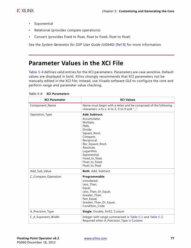
Floating-Point Operator v6.2 www.xilinx.com 77PG060 December 18, 2012
Chapter 5: Customizing and Generating the Core
• Exponential
• Relational (provides compare operations)
• Convert (provides f ixed to float, float to f ixed, float to float)
See the System Generator for DSP User Guide (UG640) [Ref 8] for more information.
Parameter Values in the XCI FileTable 5-4 defines valid entries for the XCI parameters. Parameters are case sensitive. Default values are displayed in bold. Xilinx strongly recommends that XCI parameters not be manually edited in the XCI f ile; instead, use Vivado software GUI to configure the core and perform range and parameter value checking.
Table 5-4: XCI Parameters
XCI Parameter XCI Values
Component_Name Name must begin with a letter and be composed of the following characters: a to z, A to Z, 0 to 9 and "_".
Operation_Type Add_Subtract,Accumulator,Multiply,FMA,Divide,Square_Root,Compare,Reciprocal,Rec_Square_Root,Absolute,Logarithm,Exponential,Fixed_to_float,Float_to_fixed,Float_to_float
Add_Sub_Value Both, Add, Subtract
C_Compare_Operation Programmable,Unordered,Less_Than,Equal,Less_Than_Or_Equal,Greater_Than,Not_Equal,Greater_Than_Or_Equal,Condition_Code
A_Precision_Type Single, Double, Int32, Custom
C_A_Exponent_Width Integer with range summarized in Table 5-1 and Table 5-2. Required when A_Precision_Type is Custom.

Floating-Point Operator v6.2 www.xilinx.com 78PG060 December 18, 2012
Chapter 5: Customizing and Generating the Core
C_A_Fraction_Width Integer with range summarized in Table 5-1 and Table 5-2. Required when A_Precision_Type is Custom.
Result_Precision_Type Single, Double, Int32, Custom.
C_Result_Exponent_Width Integer with range summarized in Table 5-1 and Table 5-2. Required when Result_Precision_Type is Custom.
C_Result_Fraction_Width Integer with range summarized in Table 5-1 and Table 5-2. Required when Result_Precision_Type is Custom.
C_Accum_Msb Integer with range specified in GUI. Required when Operation_Type is Accumulator.
C_Accum_Lsb Integer with range specified in GUI. Required when Operation_Type is Accumulator.
C_Accum_Input_Msb Integer with range specified in GUI. Required when Operation_Type is Accumulator.
C_Optimization Speed_OptimizedLow_Latency
C_Mult_Usage No_Usage,Medium_Usage,Full_Usage,Max_Usage
C_BRAM_Usage No_Usage,Full_Usage
Maximum_Latency False, True
C_Latency Integer with range 0 to the maximum latency of core as discussed in Latency (default is maximum latency). Required when Maximum_Latency is False.
C_Rate Integer with range 1 to maximum rate as described in Cycles per Operation (default is 1).
Has_ARESETn False, True
Has_ACLKEN False, True
C_Has_UNDERFLOW False, True
C_Has_OVERFLOW False, True
C_Has_INVALID_OP False, True
C_Has_DIVIDE_BY_ZERO False, True
C_Has_ACCUM_INPUT_OVERFLOW False, True. Used when Operation_Type is Accumulator.
C_Has_ACCUM_OVERFLOW False, True. Used when Operation_Type is Accumulator
Flow_Control Blocking, NonBlocking
Axi_Optimize_Goal Resources, Performance
Has_RESULT_TREADY True, False
Has_A_TLAST False, True
Table 5-4: XCI Parameters (Cont’d)
XCI Parameter XCI Values

Floating-Point Operator v6.2 www.xilinx.com 79PG060 December 18, 2012
Chapter 5: Customizing and Generating the Core
Output GenerationTable 5-5 shows the f iles associated with the core.
Has_A_TUSER False, True
A_TUSER_Width Integer with range 1 to 256. Default is 1.
Has_B_TLAST False, True
Has_B_TUSER False, True
B_TUSER_Width Integer with range 1 to 256. Default is 1.
Has_C_TLAST False, True
Has_C_TUSER False, True
C_TUSER_Width Integer with range 1 to 256. Default is 1.
Has_OPERATION_TLAST False, True
Has_OPERATION_TUSER False, True
OPERATION_TUSER_Width Integer with range 1 to 256. Default is 1.
RESULT_TLAST_Behv Null, Pass_A_TLAST, Pass_B_TLAST, Pass_OPERATION_TLAST, OR_All_TLASTs, AND_all_TLASTs, Pass_C_TLAST
Table 5-5: Core Files
Name Description
<component_name>.xci Input f ile containing the parameters used to customize the core.
<component_name>.veo Template f iles containing code that can be used as a model for instantiation of the customized core.
<component_name>.vho<component_name>.vhd VHDL model of the core.
<component_name>.v Structural Verilog model of the core.
/doc/pg060-floating-point.pdf /doc/floating_point_v6_2_vinfo.html Core documents
floating_point_v6_2_readme.txt Readme file for the core.
/demo_tb/tb_<component_name>.vhd Demonstration test bench for the core.
/cmodel/floating_point_v6_2_bitacc_cmodel_*.zip C model of the core.
Table 5-4: XCI Parameters (Cont’d)
XCI Parameter XCI Values
Floating-Point Operator v6.2 www.xilinx.com 80PG060 December 18, 2012
Chapter 6
Detailed Example Design
Demonstration Test BenchWhen the core is generated using the Vivado™ Design Suite, a demonstration test bench is created. This is a simple VHDL test bench that exercises the core.
The demonstration test bench source code is one VHDL f ile: demo_tb/tb_<component_name>.vhd in the Vivado output directory. The source code is comprehensively commented.
Using the Demonstration Test BenchThe demonstration test bench instantiates the generated Floating-Point Operator core.
Compile the netlist and the demonstration test bench into the work library (see your simulator documentation for more information on how to do this). Then simulate the demonstration test bench. View the test bench signals in your simulator's waveform viewer to see the operations of the test bench.
The Demonstration Test Bench in DetailThe demonstration test bench performs the following tasks:
• Instantiates the core
• Generates input data
• Generates a clock signal
• Drives the input signals of the core to demonstrate core features
• Checks that the output signals of he core obey AXI4-Stream protocol rules (data values are not checked to keep the test bench simple)
• Provides signals showing the separate fields of AXI4-Stream TDATA and TUSER signals
The demonstration test bench drives the core input signals to demonstrate the features and modes of operation of the core. The operations performed by the demonstration test bench
Floating-Point Operator v6.2 www.xilinx.com 81PG060 December 18, 2012
Chapter 6: Detailed Example Design
are appropriate for the configuration of the generated core, and are a subset of the following operations:
1. An initial phase where the core is initialized and no operations are performed.
2. Perform a single operation, and wait for the result.
3. Perform 100 consecutive operations with incrementing data.
4. Perform operations while demonstrating the AXI4-Stream control signals’ use and effects.
5. If ACLKEN is present: Demonstrate the effect of toggling aclken.
6. If ARESETn is present: Demonstrate the effect of asserting aresetn.
7. Demonstrate the handling of special floating-point values (NaN, zero, infinity).
Customizing the Demonstration Test BenchThe clock frequency of the core can be modified by changing the CLOCK_PERIOD constant.
For instructions on simulating your core, see the Vivado Design Suite User Guide: Logic Simulation (UG900) [Ref 12].
For instruction on implementing your core, see Vivado Design Suite User Guide: Implementation (UG904) [Ref 13].

Floating-Point Operator v6.2 www.xilinx.com 82PG060 December 18, 2012
Chapter 7
Constraining the CoreThere are no constraints associated with this core.

Floating-Point Operator v6.2 www.xilinx.com 83PG060 December 18, 2012
SECTION III: APPENDICES
Migrating
Debugging
Additional Resources

Floating-Point Operator v6.2 www.xilinx.com 84PG060 December 12, 2012
Appendix A
MigratingIn the Vivado Design Suite, you can update an existing XCO file from versions 4.0, 5.0, 6.0 and 6.1 to Floating-Point Operator, v6.2.
Note: For v4.0 and v5.0 the upgrade mechanism alone does not create a core compatible with v6.2. See Instructions for Minimum Change Migration. Floating-Point Operator v6.2 has parameters additional to v4.0 and v5.0 for AXI4-Stream support.
Floating-Point Operator v6.2 is backwards compatible with v6.1 both in terms of parameters and ports. Figure A-1 shows the changes to XCO parameters from versions 4.0, 5.0, 6.0 and 6.1 to version 6.2. For clarity, XCO parameters with no changes are not shown.
See also Vivado Design Suite Migration Methodology Guide (UG911) [Ref 14] for information on migrating to the Vivado™ Design Suite.
Parameter Changes in the XCO/XCI FileTable A-1: XCO/XCI Parameter Changes from v4.0, v5.0, v6.0 and v6.1 to v6.2(1)
Version 4.0 and 5.0 Version 6.2 Notes
C_Has_CE Has_ACLKEN Renamed only
C_Has_SCLR Has_ARESETn Renamed only. While the sense of the aresetn signal has changed (now active-Low), this XCO parameter determined whether or not the pin exists and has not changed.
C_Latency C_Latency Depending on the AXI4-Stream Flow Control options selected (Blocking/NonBlocking), a minimum latency greater than previous core versions might be imposed.
Flow_Control New as of version 6.0
Axi_Optimize_Goal New as of version 6.0
Has_RESULT_TREADY New as of version 6.0
Has_A_TLAST New as of version 6.0
Has_A_TUSER New as of version 6.0
A_TUSER_Width New as of version 6.0

Floating-Point Operator v6.2 www.xilinx.com 85PG060 December 12, 2012
Appendix A: Migrating
Port ChangesTable A-2 details the changes to port naming, additional or deprecated ports and polarity changes from v4.0, v5.0, v6.0 and v6.1 to v6.2.
Has_B_TLAST New as of version 6.0
Has_B_TUSER New as of version 6.0
B_TUSER_Width New as of version 6.0
Has_OPERATION_TLAST New as of version 6.0
Has_OPERATION_TUSER New as of version 6.0
OPERATION_TUSER_Width New as of version 6.0
RESULT_TLAST_Behv New as of version 6.0
Has_C_TLAST New as of version 6.2
Has_C_TUSER New as of version 6.2
C_TUSER_Width New as of version 6.2
C_Has_ACCUM_INPUT_OVERFLOW New as of version 6.2
C_Has_ACCUM_OVERFLOW New as of version 6.2
C_Accum_Msb New as of version 6.2
C_Accum_Lsb New as of version 6.2
C_Accum_Input_Msb New as of version 6.2
Notes: 1. Parameters in v6.0, v6.1 and v6.2 are unchanged except for the additions required for new operators.
Table A-2: Port Changes from v4.0, v5.0, v6.0 and v6.1 to v6.2(1)
Versions 4.0 and 5.0 Version 6.2 Notes
CLK aclk Rename only
CE aclken Rename only
SCLR aresetn Rename and change of sense (now active-Low). Must now be asserted for at least two clock cycles to effect a reset.
A(N-1:0) s_axis_a_tdata (byte (N)-1:0) byte (N) is to round N up to the next multiple of 8
B(N-1:0) s_axis_b_tdata (byte (N)-1:0) byte (N) is to round N up to the next multiple of 8
OPERATION(5 : 0) s_axis_operation_tdata (7 : 0)
Table A-1: XCO/XCI Parameter Changes from v4.0, v5.0, v6.0 and v6.1 to v6.2(1) (Cont’d)
Version 4.0 and 5.0 Version 6.2 Notes
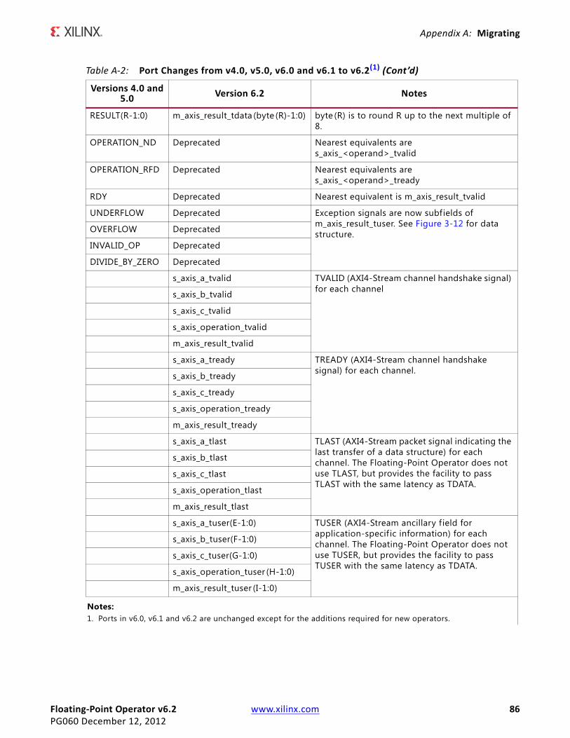
Floating-Point Operator v6.2 www.xilinx.com 86PG060 December 12, 2012
Appendix A: Migrating
RESULT(R-1:0) m_axis_result_tdata (byte (R)-1:0) byte (R) is to round R up to the next multiple of 8.
OPERATION_ND Deprecated Nearest equivalents are s_axis_<operand>_tvalid
OPERATION_RFD Deprecated Nearest equivalents are s_axis_<operand>_tready
RDY Deprecated Nearest equivalent is m_axis_result_tvalid
UNDERFLOW Deprecated Exception signals are now subfields of m_axis_result_tuser. See Figure 3-12 for data structure.OVERFLOW Deprecated
INVALID_OP Deprecated
DIVIDE_BY_ZERO Deprecated
s_axis_a_tvalid TVALID (AXI4-Stream channel handshake signal) for each channels_axis_b_tvalid
s_axis_c_tvalid
s_axis_operation_tvalid
m_axis_result_tvalid
s_axis_a_tready TREADY (AXI4-Stream channel handshake signal) for each channel.s_axis_b_tready
s_axis_c_tready
s_axis_operation_tready
m_axis_result_tready
s_axis_a_tlast TLAST (AXI4-Stream packet signal indicating the last transfer of a data structure) for each channel. The Floating-Point Operator does not use TLAST, but provides the facility to pass TLAST with the same latency as TDATA.
s_axis_b_tlast
s_axis_c_tlast
s_axis_operation_tlast
m_axis_result_tlast
s_axis_a_tuser(E-1:0) TUSER (AXI4-Stream ancillary field for application-specif ic information) for each channel. The Floating-Point Operator does not use TUSER, but provides the facility to pass TUSER with the same latency as TDATA.
s_axis_b_tuser(F-1:0)
s_axis_c_tuser(G-1:0)
s_axis_operation_tuser (H-1:0)
m_axis_result_tuser (I-1:0)
Notes: 1. Ports in v6.0, v6.1 and v6.2 are unchanged except for the additions required for new operators.
Table A-2: Port Changes from v4.0, v5.0, v6.0 and v6.1 to v6.2(1) (Cont’d)
Versions 4.0 and 5.0 Version 6.2 Notes

Floating-Point Operator v6.2 www.xilinx.com 87PG060 December 12, 2012
Appendix A: Migrating
Functionality Changes
Latency ChangesThere is no change in latency from Floating-Point Operator v6.0 or v6.1 to v6.2. The latency of Floating-Point Operator v6.2 is different compared to v4.0 and v5.0 in general. The update process cannot account for this and guarantee equivalent performance.
Importantly, when in Blocking Mode, the latency of the core is variable, so only the minimum possible latency can be determined.
When in Non-Blocking Mode, the latency of the core for equivalent performance is the same as that for the equivalent configuration of v4.0 and v5.0.
Special Considerations when Migrating to AXI
Instructions for Minimum Change MigrationTo configure the Floating-Point Operator v6.2 to most closely mimic the behavior of pre-AXI versions the translation is as follows:
Parameters
Set Flow Control to NonBlocking and uncheck all AXI4-Stream channel options (TUSER and TLAST).
Ports
Rename and map signals as detailed in Port Changes. Tie all TVALID signals on input channels (A, B, OPERATION) to 1.
Remember to account for aresetn being active-Low, and the requirement to assert aresetn for at least two clock cycles to reset the core.
Performance
The fully-pipelined latency of the v6.2 core with a Non-Blocking interface configuration is the same as the v4.0 and v5.0 cores.

Floating-Point Operator v6.2 www.xilinx.com 88PG060 December 12, 2012
Appendix B
DebuggingThis appendix includes details about resources available on the Xilinx Support website and debugging tools. In addition, this appendix provides a step-by-step debugging process and a flow diagram to guide you through debugging the Floating-Point Operator core.
The following topics are included in this appendix:
• Finding Help on Xilinx.com
• Debug Tools
• Simulation Debug
• Interface Debug
Finding Help on Xilinx.comTo help in the design and debug process when using the Floating-Point Operator, the Xilinx Support web page (www.xilinx.com/support) contains key resources such as product documentation, release notes, answer records, information about known issues, and links for opening a Technical Support WebCase.
DocumentationThis product guide is the main document associated with the Floating-Point Operator. This guide, along with documentation related to all products that aid in the design process, can be found on the Xilinx Support web page (www.xilinx.com/support) or by using the Xilinx Documentation Navigator.
Download the Xilinx Documentation Navigator from the Design Tools tab on the Downloads page (www.xilinx.com/download). For more information about this tool and the features available, open the online help after installation.
Release NotesKnown issues for all cores, including the Floating-Point Operator are described in theIP Release Notes Guide (XTP025).

Floating-Point Operator v6.2 www.xilinx.com 89PG060 December 12, 2012
Appendix B: Debugging
Solution CentersSee the Xilinx Solution Centers for support on devices, software tools, and intellectual property at all stages of the design cycle. Topics include design assistance, advisories, and troubleshooting tips.
Known IssuesAnswer Records include information about commonly encountered problems, helpful information on how to resolve these problems, and any known issues with a Xilinx product. Answer Records are created and maintained daily ensuring that users have access to the most accurate information available.
Answer Records for this core are listed below, and can also be located by using the Search Support box on the main Xilinx support web page. To maximize your search results, use proper keywords such as
• Product name
• Tool message(s)
• Summary of the issue encountered
A filter search is available after results are returned to further target the results.
Answer Records for the Floating-Point Operator
Known issues for all cores, including the Floating-Point Operator are described in theIP Release Notes Guide (XTP025).
Contacting Technical SupportXilinx provides premier technical support for customers encountering issues that require additional assistance.
To contact Xilinx Technical Support:
1. Navigate to www.xilinx.com/support.
2. Open a WebCase by selecting the WebCase link located under Support Quick Links.
When opening a WebCase, include:
• Target FPGA including package and speed grade.
• All applicable Xilinx Design Tools and simulator software versions.
• Additional f iles based on the specif ic issue might also be required. See the relevant sections in this debug guide for guidelines about which f ile(s) to include with the WebCase.
Floating-Point Operator v6.2 www.xilinx.com 90PG060 December 12, 2012
Appendix B: Debugging
Debug ToolsThere are many tools available to address Floating-Point Operator design issues. It is important to know which tools are useful for debugging various situations.
ChipScope Pro ToolThe ChipScope™ Pro debugging tool inserts logic analyzer, bus analyzer, and virtual I/O cores directly into your design. The ChipScope Pro debugging tool allows you to set trigger conditions to capture application and integrated block port signals in hardware. Captured signals can then be analyzed through the ChipScope Pro logic analyzer tool. For detailed information for using the ChipScope Pro debugging tool, see www.xilinx.com/tools/cspro.htm.
C-Model ReferencePlease see Chapter 4, C Model Reference in this guide for tips and instructions for using the provided C-Model f iles to debug your design.
Simulation DebugThe First Result After Reset is MissingWhen the Floating-Point Operator core is configured to use Non-Blocking mode, any transaction input in the cycle following the de-assertion of aresetn is lost. For more information, see Non-Blocking Mode in the AXI4-Stream Considerations section.
Interface DebugAXI4-Stream InterfacesIf data is not being transmitted or received, check the following conditions:
• If transmit <interface_name>_tready is stuck low following the <interface_name>_tvalid input being asserted, the core cannot send data.
• If the receive <interface_name>_tvalid is stuck low, the core is not receiving data.
• Check that the ACLK inputs are connected and toggling.
• Check that the AXI4-Stream waveforms are being followed. See AXI4-Stream Considerations.

Floating-Point Operator v6.2 www.xilinx.com 91PG060 December 12, 2012
Appendix C
Additional Resources
Xilinx ResourcesFor support resources such as Answers, Documentation, Downloads, and Forums, see the Xilinx Support website at:
www.xilinx.com/support
For a glossary of technical terms used in Xilinx documentation, see:
www.xilinx.com/company/terms.htm
References1. ANSI/IEEE, IEEE Standard for Binary Floating-Point Arithmetic, ANSI/IEEE Standard
754-2008. IEEE-754.
2. The GNU Multiple Precision Arithmetic (GMP) Library gmplib.org
3. The GNU Multiple Precision Floating-Point Reliable (MPFR) Library www.mpfr.org
4. The GNU Multiple Precision Integers and Rationals (MPIR) library www.mpir.org
5. Multiple Precision Arithmetic on Windows, Brian Gladman:http://gladman.plushost.co.uk/oldsite/computing/gmp4win.php
6. Xilinx AXI Reference Guide (UG761)
7. AMBA 4 AXI4-Stream Protocol Version 1.0 Specif ication
8. System Generator for DSP User Guide (UG640)
9. Vivado Design Suite User Guides website
10. Vivado Design Suite User Guide: Using the Vivado IDE (UG893)
11. Vivado Design Suite User Guide: Designing with IP (UG896)
12. Vivado Design Suite User Guide: Logic Simulation (UG900)

Floating-Point Operator v6.2 www.xilinx.com 92PG060 December 12, 2012
Appendix C: Additional Resources
13. Vivado Design Suite User Guide: Implementation (UG904)
14. Vivado Design Suite Migration Methodology Guide (UG911)
Revision HistoryThe following table shows the revision history for this document.
Notice of DisclaimerThe information disclosed to you hereunder (the “Materials”) is provided solely for the selection and use of Xilinx products. To the maximum extent permitted by applicable law: (1) Materials are made available “AS IS” and with all faults, Xilinx hereby DISCLAIMS ALL WARRANTIES AND CONDITIONS, EXPRESS, IMPLIED, OR STATUTORY, INCLUDING BUT NOT LIMITED TO WARRANTIES OF MERCHANTABILITY, NON-INFRINGEMENT, OR FITNESS FOR ANY PARTICULAR PURPOSE; and (2) Xilinx shall not be liable (whether in contract or tort, including negligence, or under any other theory of liability) for any loss or damage of any kind or nature related to, arising under, or in connection with, the Materials (including your use of the Materials), including for any direct, indirect, special, incidental, or consequential loss or damage (including loss of data, profits, goodwill, or any type of loss or damage suffered as a result of any action brought by a third party) even if such damage or loss was reasonably foreseeable or Xilinx had been advised of the possibility of the same. Xilinx assumes no obligation to correct any errors contained in the Materials or to notify you of updates to the Materials or to product specifications. You may not reproduce, modify, distribute, or publicly display the Materials without prior written consent. Certain products are subject to the terms and conditions of the Limited Warranties which can be viewed at http://www.xilinx.com/warranty.htm; IP cores may be subject to warranty and support terms contained in a license issued to you by Xilinx. Xilinx products are not designed or intended to be fail-safe or for use in any application requiring fail-safe performance; you assume sole risk and liability for use of Xilinx products in Critical Applications: http://www.xilinx.com/warranty.htm#critapps.© Copyright 2012 Xilinx, Inc. Xilinx, the Xilinx logo, Artix, ISE, Kintex, Spartan, Virtex, Vivado, Zynq, and other designated brands included herein are trademarks of Xilinx in the United States and other countries. ARM is a registered trademark of ARM in the EU and other countries. The AMBA trademark is a registered trademark of ARM Limited. MATLAB and Simulink are registered trademarks of The MathWorks, Inc. All other trademarks are the property of their respective owners.
Date Version Revision
07/25/12 1.0 Initial Xilinx release. This Product Guide is derived from DS816 and UG812.
12/18/12 2.0 • Updated to core v6.2 and Vivado Design Suite 2012.4.• Removed support for ISE Design Suite, and Virtex-6,
Spartan-6 and Zynq-7000 devices.• Added support for accumulator, fused multiply-add and
exponential operators. • Updated Resource Utilization numbers.• Added C Input Channel.• Added Appendix B, Debugging.