logic and data representation revision. and gate a b a b all inputs have to be true ( i.e 1) for the...
TRANSCRIPT
Logic and data representation
Revision
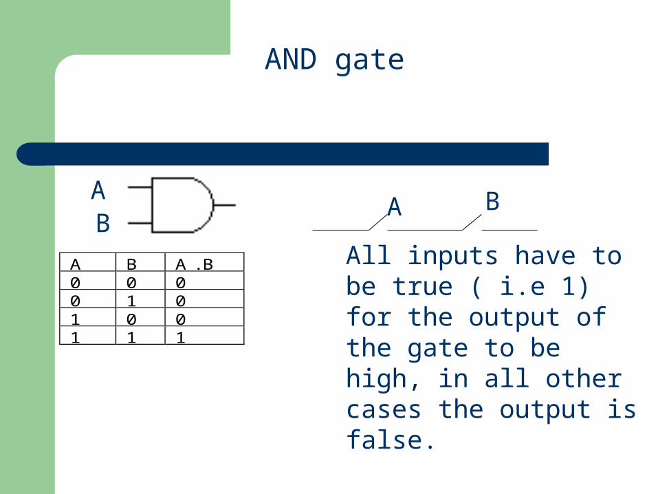
AND gate
AB
A B
A B A . B0 0 00 1 01 0 01 1 1
All inputs have to be true ( i.e 1) for the output of the gate to be high, in all other cases the output is false.
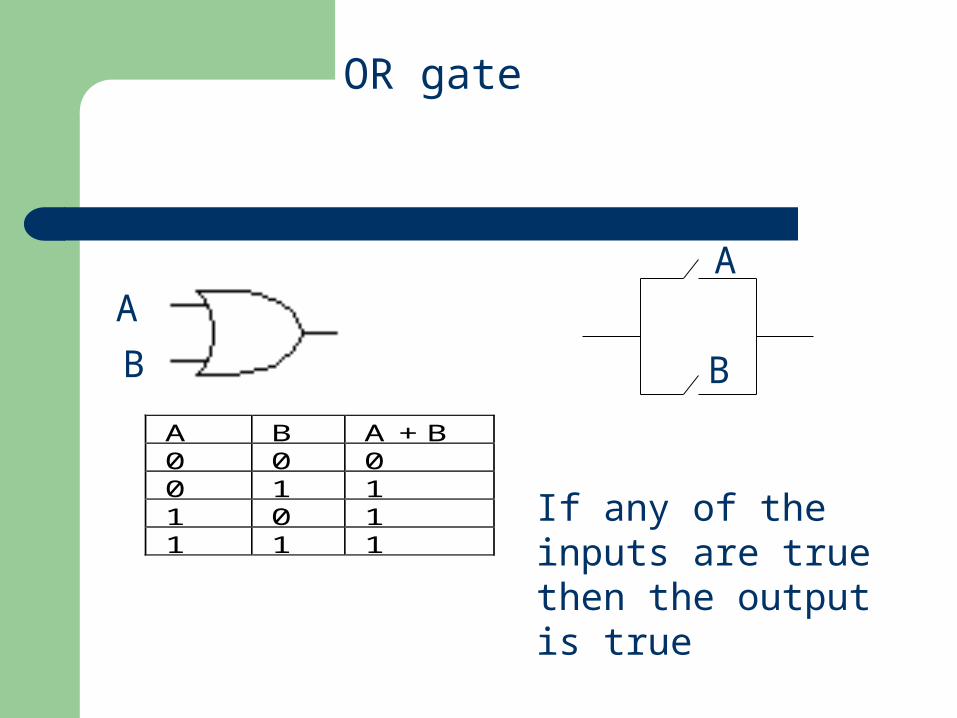
OR gate
A B A + B0 0 00 1 11 0 11 1 1
A
B
A
B
If any of the inputs are true then the output is true
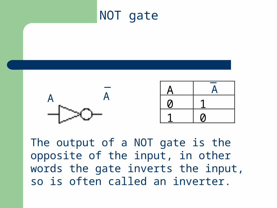
A0 11 0
A_
A
_A
NOT gate
The output of a NOT gate is the opposite of the input, in other words the gate inverts the input, so is often called an inverter.
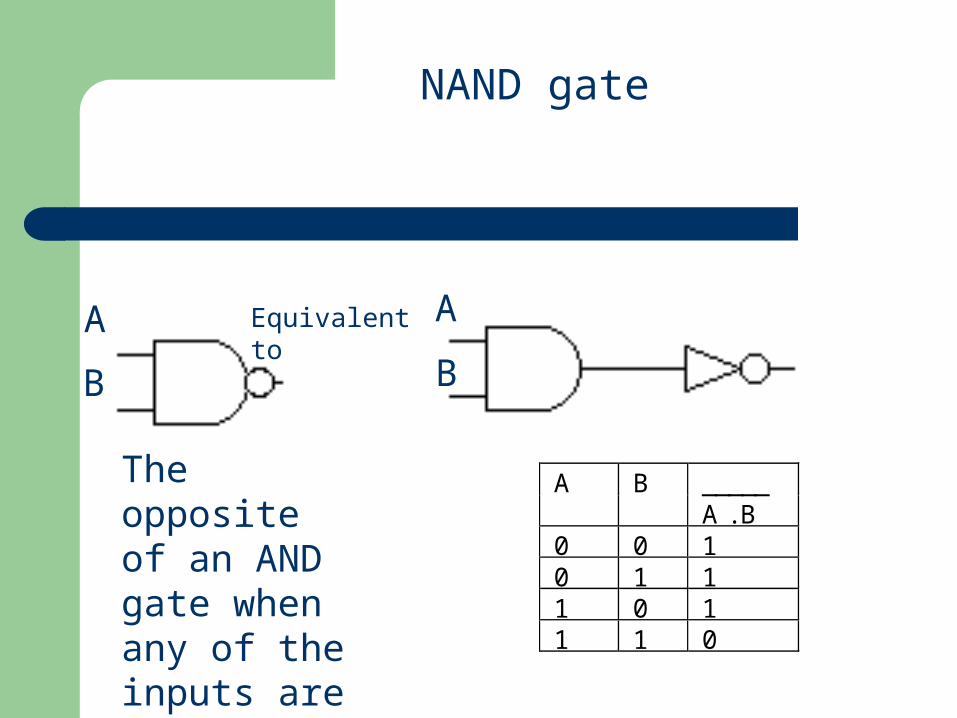
NAND gate
_____A BA . B
0 0 10 1 11 0 11 1 0
The opposite of an AND gate when any of the inputs are false the output is true
Equivalentto
A
B
A
B
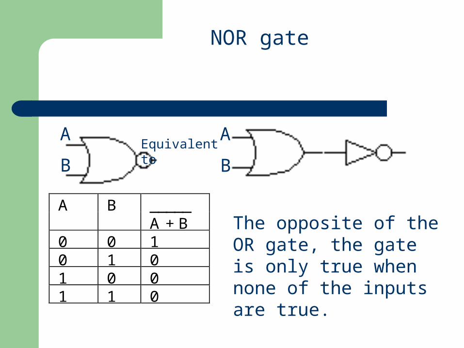
_____A BA + B
0 0 10 1 01 0 01 1 0
A
B
A
BEquivalentto
The opposite of the OR gate, the gate is only true when none of the inputs are true.
NOR gate
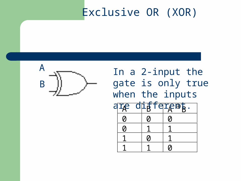
A B A B0 0 00 1 11 0 11 1 0
A
B
Exclusive OR (XOR)
In a 2-input the gate is only true when the inputs are different.
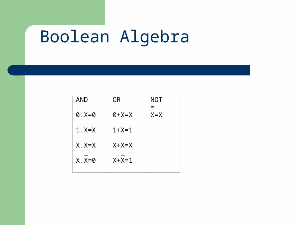
AND OR NOT = 0.X=0 0+X=X X=X 1.X=X 1+X=1 X.X=X X+X=X _ _ X.X=0 X+X=1
Boolean Algebra
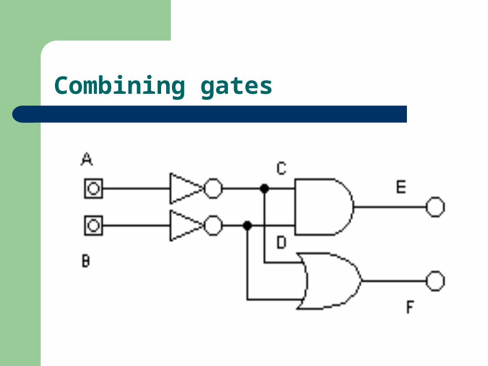
Combining gates
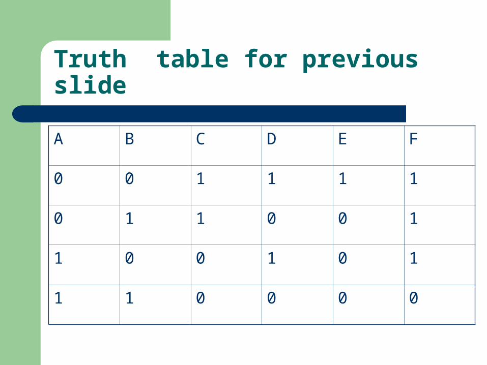
Truth table for previous slide
A B C D E F
0 0 1 1 1 1
0 1 1 0 0 1
1 0 0 1 0 1
1 1 0 0 0 0
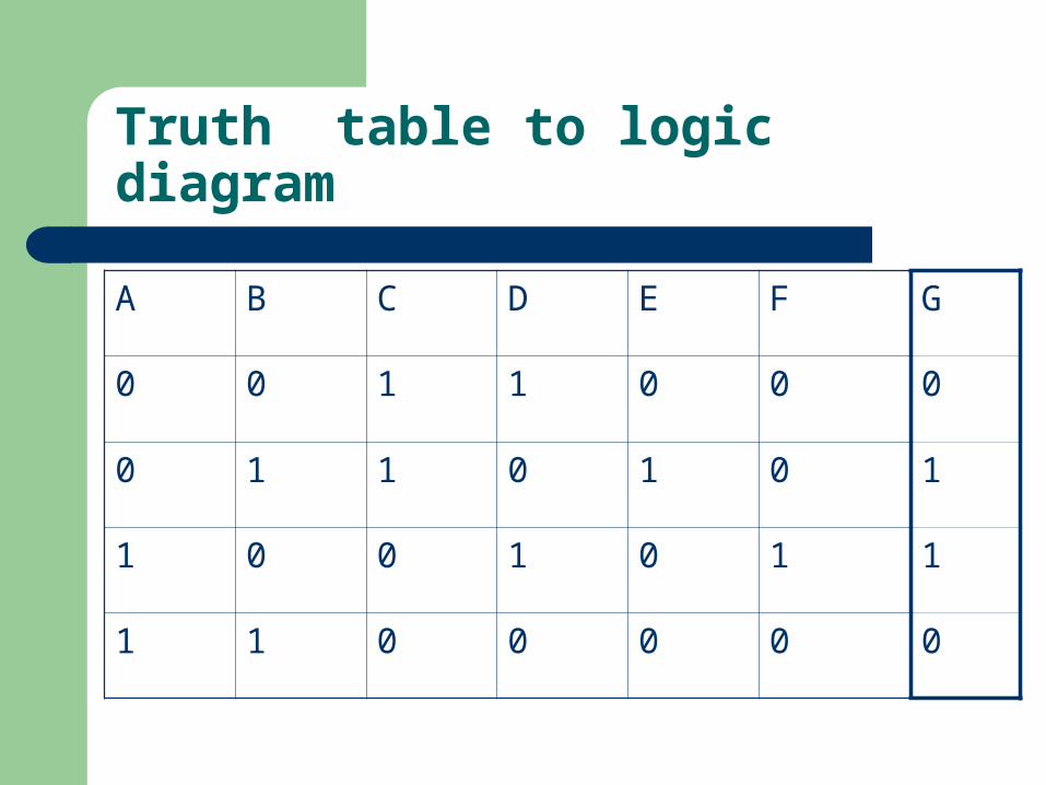
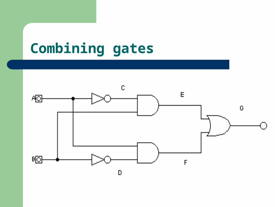
Truth table to logic diagram
A B C D E F G
0 0 1 1 0 0 0
0 1 1 0 1 0 1
1 0 0 1 0 1 1
1 1 0 0 0 0 0
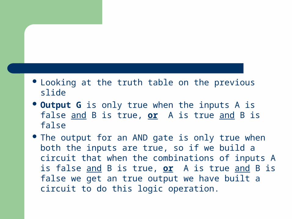
Looking at the truth table on the previous slide Output G is only true when the inputs A is false
and B is true, or A is true and B is false The output for an AND gate is only true when both
the inputs are true, so if we build a circuit that when the combinations of inputs A is false and B is true, or A is true and B is false we get an true output we have built a circuit to do this logic operation.
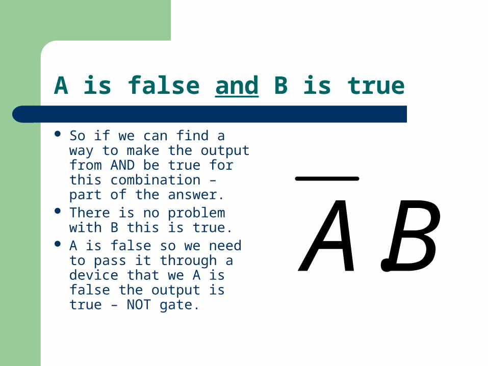
A is false and B is true
So if we can find a way to make the output from AND be true for this combination – part of the answer.
There is no problem with B this is true.
A is false so we need to pass it through a device that we A is false the output is true – NOT gate.
BA.
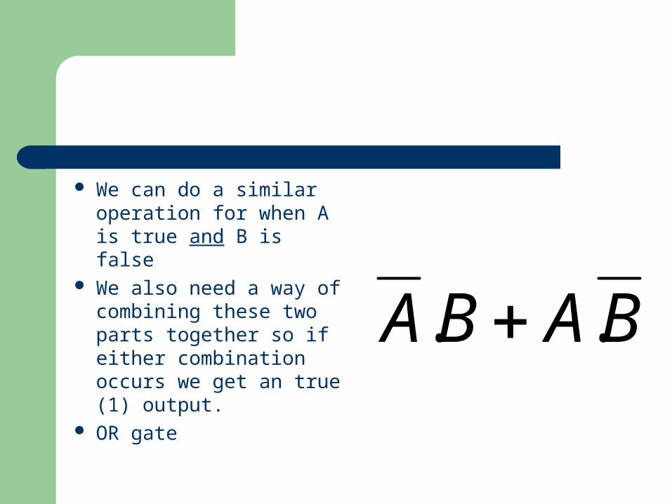
We can do a similar operation for when A is true and B is false
We also need a way of combining these two parts together so if either combination occurs we get an true (1) output.
OR gate
BABA ..
Combining gates
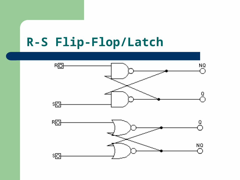
R-S Flip-Flop/Latch
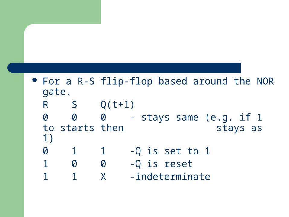
For a R-S flip-flop based around the NOR gate.R S Q(t+1)0 0 0 - stays same (e.g. if 1 to starts then stays as 1) 0 1 1 -Q is set to 11 0 0 -Q is reset1 1 X -indeterminate
Where Q(t) is the current value (or state) of the output Q and Q(t+1) is the state of Q that will be produce.
X is indeterminate (due to the outputs dependent on which gate changes first)
D-type
Data (D) only appears at the output Q on a clock pulse.
So if D=1 on a clock pulse, R=0,S=1 and Q=1.
So if D=0 on a clock pulse R=1,S=0 and Q=0.
Otherwise Q stays the same.
Shift Register
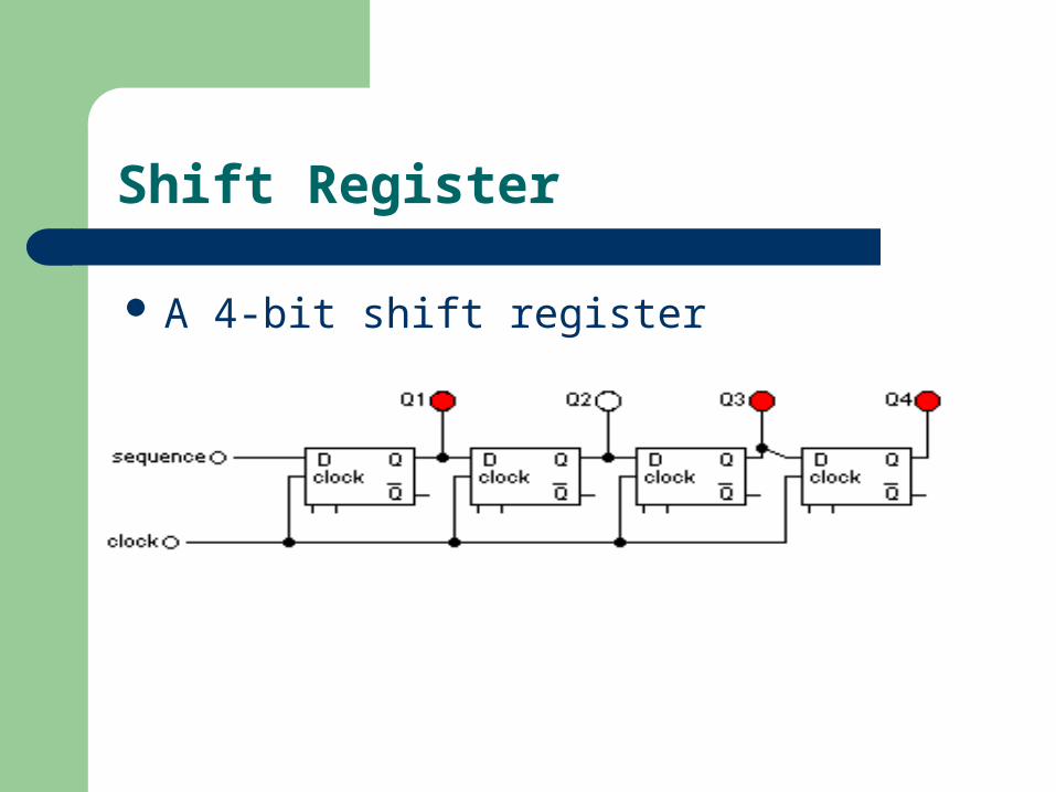
A 4-bit shift register
Shift Register
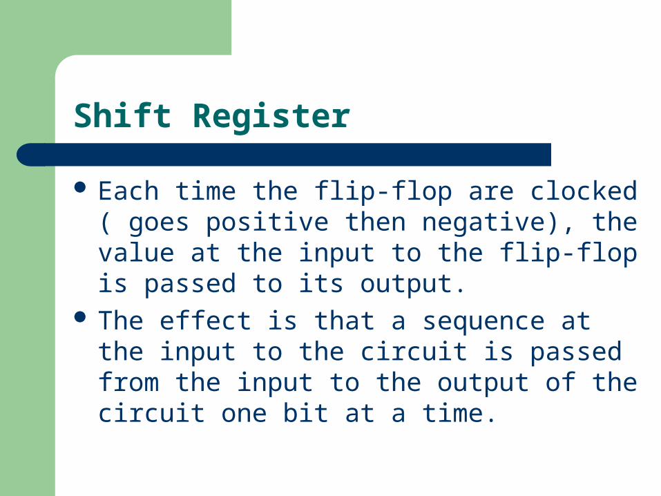
Each time the flip-flop are clocked ( goes positive then negative), the value at the input to the flip-flop is passed to its output.
The effect is that a sequence at the input to the circuit is passed from the input to the output of the circuit one bit at a time.
J-K Flip-Flop
Three inputs - J,K,and clock This is a master-slave arrangement, the inputs
are isolated from the outputs by the second latch, which does not change until after the master has ‘latched’.
J-K Flip-Flop
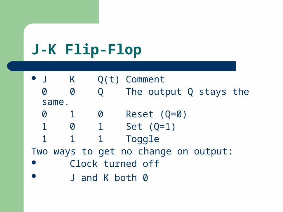
J K Q(t) Comment0 0 Q The output Q stays the same.0 1 0 Reset (Q=0)1 0 1 Set (Q=1)1 1 1 Toggle
Two ways to get no change on output: Clock turned off J and K both 0
Numbering Systems (Binary)
The two-state nature of logic gates means the use of 0 or 1, as the basic unit of the count is natural.
Data is represented by binary digits (bits), words are groups of bits, but by convention the
size of words are multiples of 8 bits (or a byte). bit furthest right as the least significant bit (lsb)
and bit furthest left as the most significant bit as the
most significant bit (msb).
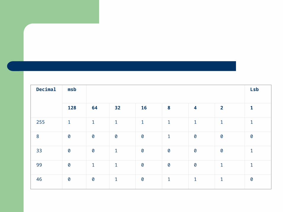
Decimal
msb Lsb
128 64 32 16 8 4 2 1
255 1 1 1 1 1 1 1 1
8 0 0 0 0 1 0 0 0
33 0 0 1 0 0 0 0 1
99 0 1 1 0 0 0 1 1
46 0 0 1 0 1 1 1 0
Numbering system (Hexadecimal)
A base-16 system with 16 possible digits {0,1,2,3,4,5,6,7,8,9,A,B,C,D,E,F}. Each hexadecimal number can be represented by 4 bits .
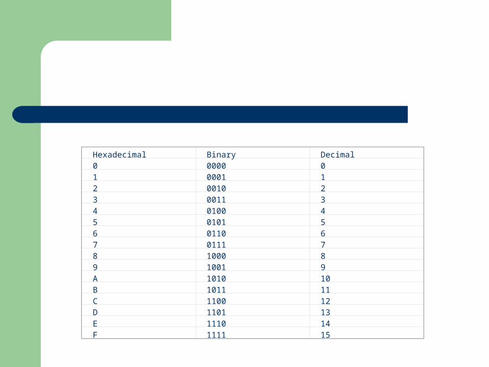
Hexadecimal Binary Decimal0 0000 01 0001 12 0010 23 0011 34 0100 45 0101 56 0110 67 0111 78 1000 89 1001 9A 1010 10B 1011 11C 1100 12D 1101 13E 1110 14F 1111 15
Negative and Positive Numbers
So far is the discussion no mention has been made about the being able to represent negative numbers, how can both negative and positive number be stored.
2’s complement
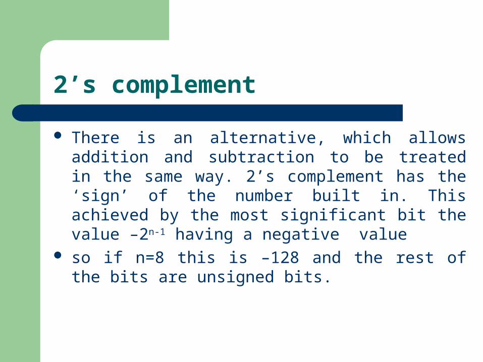
There is an alternative, which allows addition and subtraction to be treated in the same way. 2’s complement has the ‘sign’ of the number built in. This achieved by the most significant bit the value –2n-1 having a negative value
so if n=8 this is –128 and the rest of the bits are unsigned bits.
2’s complement
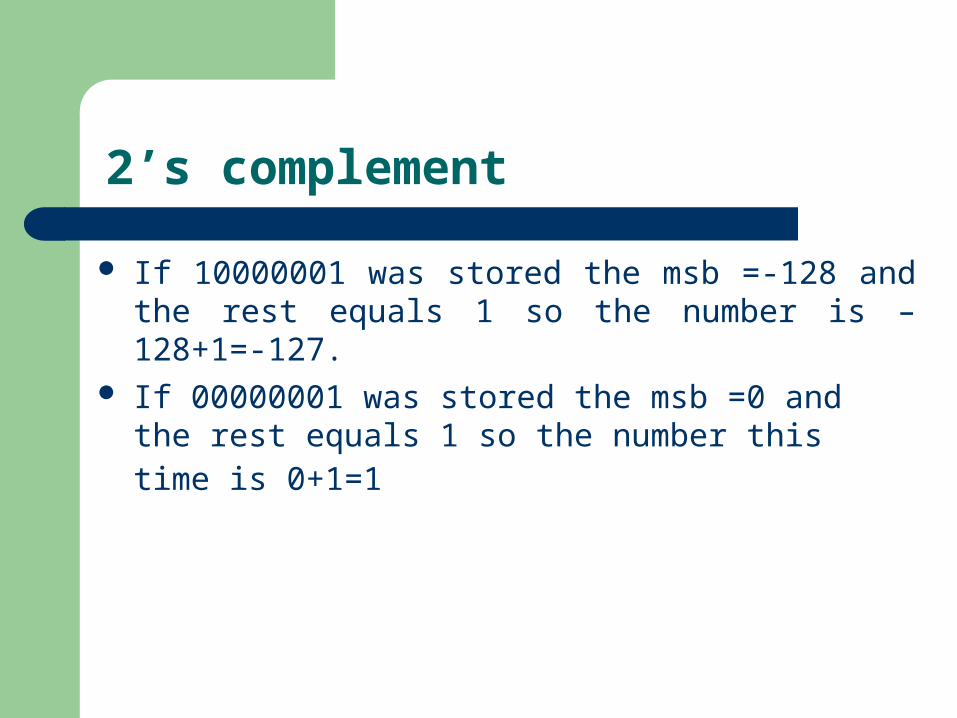
If 10000001 was stored the msb =-128 and the rest equals 1 so the number is –128+1=-127.
If 00000001 was stored the msb =0 and the rest equals 1 so the number this time is 0+1=1
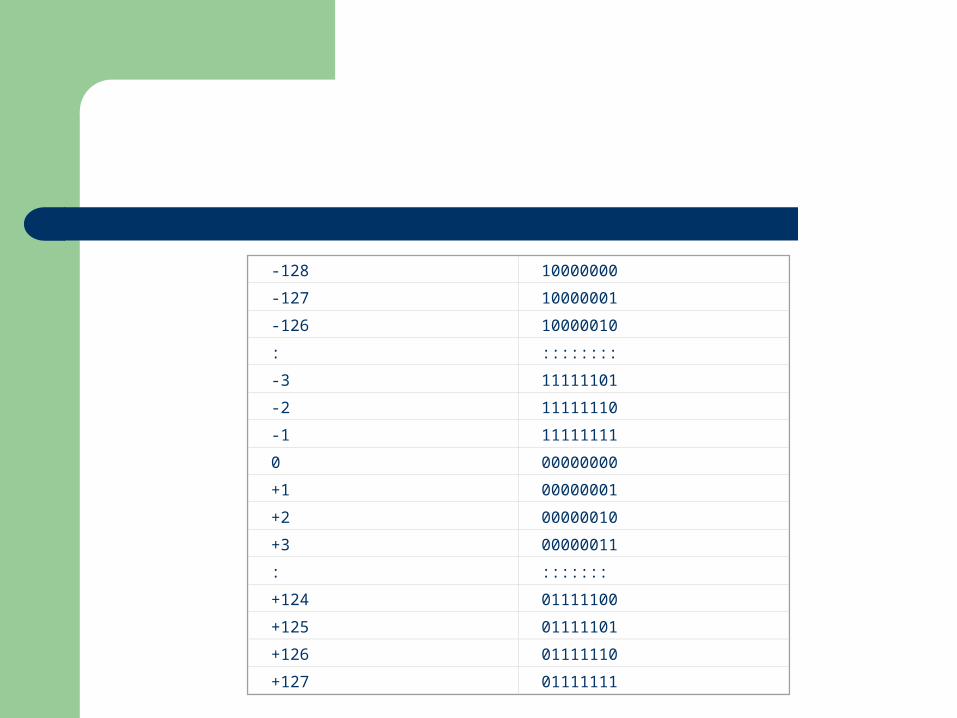
-128 10000000
-127 10000001
-126 10000010
: ::::::::
-3 11111101
-2 11111110
-1 11111111
0 00000000
+1 00000001
+2 00000010
+3 00000011
: :::::::
+124 01111100
+125 01111101
+126 01111110
+127 01111111
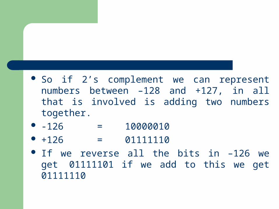
So if 2’s complement we can represent numbers between –128 and +127, in all that is involved is adding two numbers together.
-126 = 10000010 +126 = 01111110 If we reverse all the bits in –126 we get
01111101 if we add to this we get 01111110
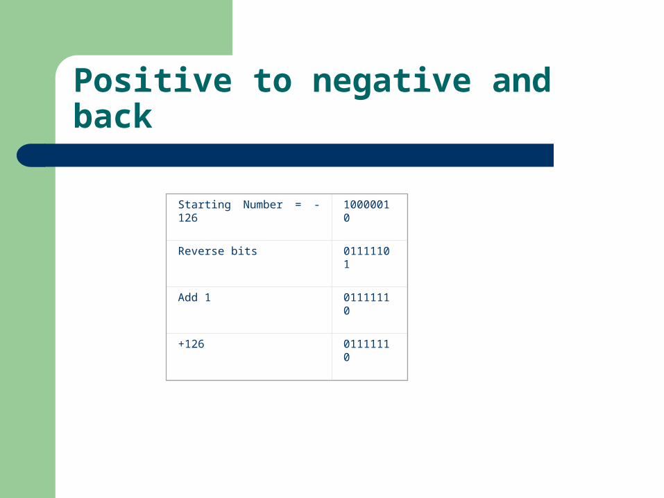
Starting Number = -126 10000010
Reverse bits 01111101
Add 1 01111110
+126 01111110
Positive to negative and back
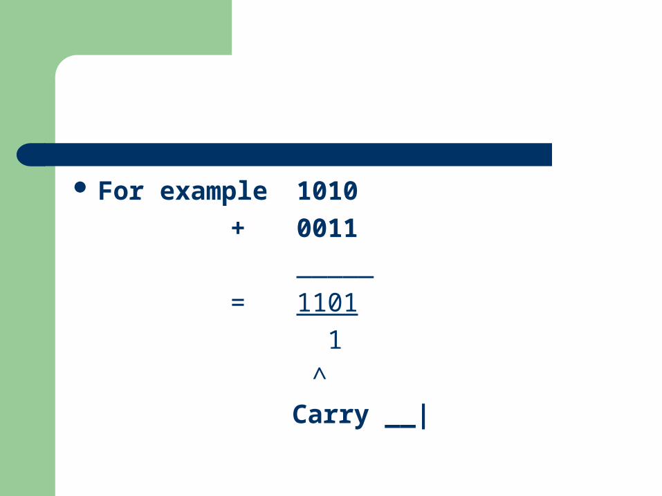
For example 1010+ 0011
_____
= 1101 1
^ Carry __|
Binary subtraction
Binary subtraction is performed by converting the second number into it’s two’s complement and adding. So there is not a need for a subtracting circuit.
As an example: 14-6

Subtraction Example
Number A=14 00001110
Number B=6 00000110
Reverse bits in Number B 11111001
+1 11111010
B 2’s Complement = C 11111010
14 00001110
2’s Complement of 6 11111010
add
8 00001000
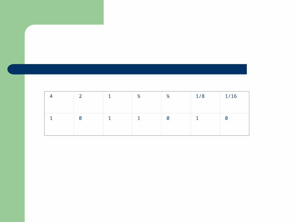
4 2 1 ½ ¼ 1/8 1/16
1 0 1 1 0 1 0
Floating-point numbers
Often we want to represent very small, very large numbers or numbers with fractional parts. For example, 33550000 or 0.00000001451. One way of doing this is scientific notation where these numbers are split into two parts a number with a decimal point within it (called the mantissa) and a power of 10 (called the exponent).
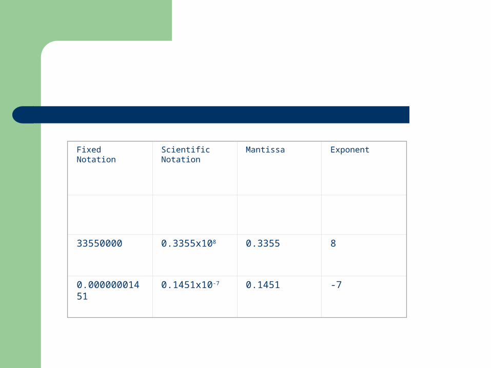
Fixed Notation Scientific Notation
Mantissa Exponent
33550000 0.3355x10⁸ 0.3355 8
0.00000001451
0.1451x10⁻⁷ 0.1451 -7
The decimal number 5.625 could be represented as 101.101. If we use this mantissa and exponent idea, it could also be written as 1.01101x22 (Normalised) where the exponent shows the final position of the binary point relative to the current position.
Because the binary point can be altered depending on the magnitude of the exponent, it often refereed to as a floating-point representation.
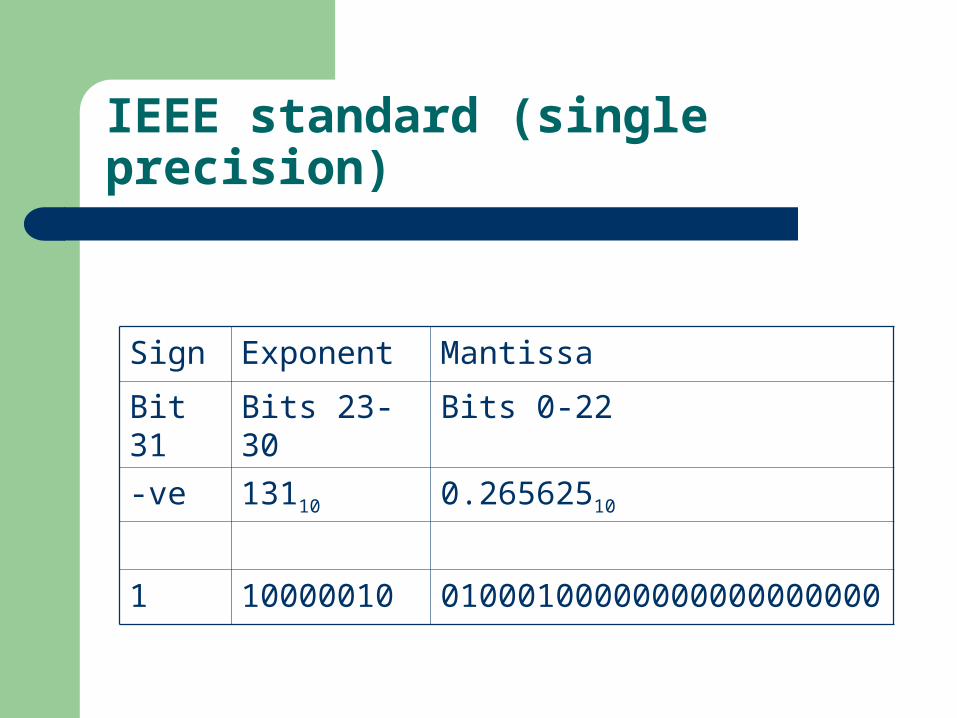
IEEE standard (single precision)
Sign Exponent Mantissa
Bit 31 Bits 23-30 Bits 0-22
-ve 13110 0.26562510
1 10000010 01000100000000000000000
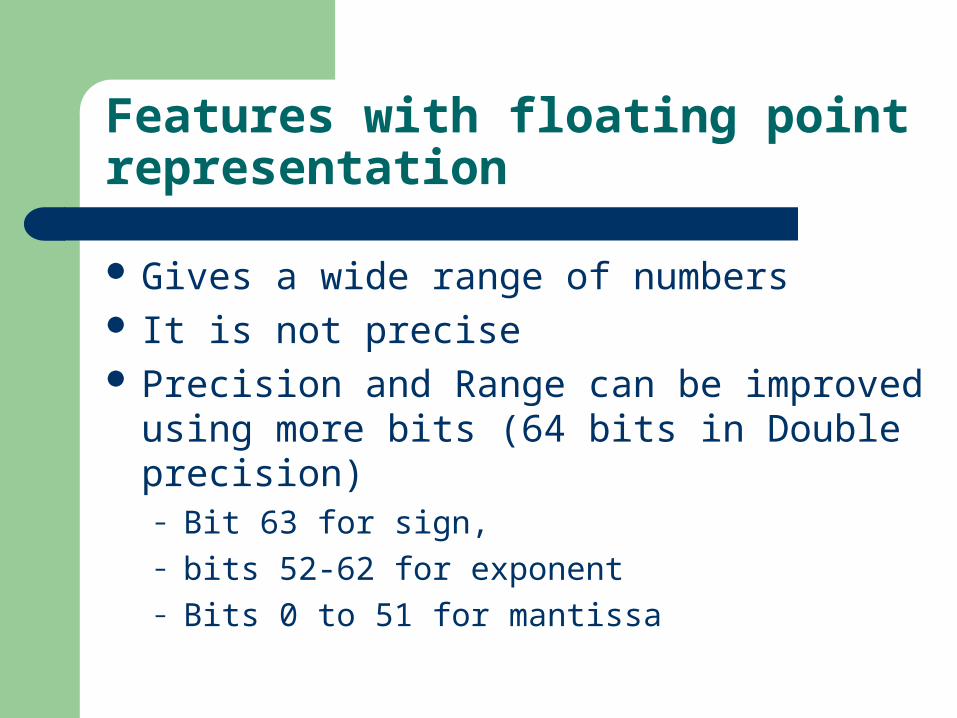
Features with floating point representation
Gives a wide range of numbers It is not precise Precision and Range can be improved using
more bits (64 bits in Double precision)– Bit 63 for sign, – bits 52-62 for exponent– Bits 0 to 51 for mantissa
ASCII
Most common text representation. Each character has a code. Special characters such as space, return, etc
have codes. American Standards Code for Information
Interchange. Alternatives: EBCDIC not widely used.
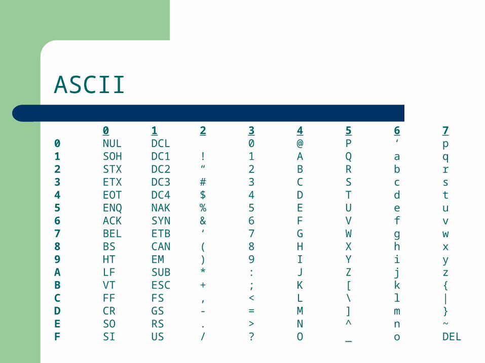
ASCII
0 1 2 3 4 5 6 70 NUL DCL 0 @ P ‘ p1 SOH DC1 ! 1 A Q a q2 STX DC2 “ 2 B R b r3 ETX DC3 # 3 C S c s4 EOT DC4 $ 4 D T d t5 ENQ NAK % 5 E U e u6 ACK SYN & 6 F V f v7 BEL ETB ‘ 7 G W g w8 BS CAN ( 8 H X h x9 HT EM ) 9 I Y i yA LF SUB * : J Z j zB VT ESC + ; K [ k {C FF FS , < L \ l |D CR GS - = M ] m }E SO RS . > N ^ n ~F SI US / ? O _ o DEL
Unicode
ASCII used 7 bits (often the 8th bit used to help check the data was transferred correctly).
Therefore, limited a small character set.
Unicode is a 16-bit system, and can deal with the requirements of the modern system, with the need for different character sets for different languages.
ASCII
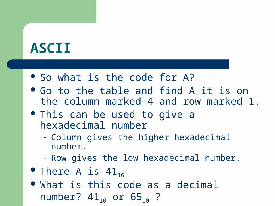
So what is the code for A? Go to the table and find A it is on the column
marked 4 and row marked 1. This can be used to give a hexadecimal
number– Column gives the higher hexadecimal number.– Row gives the low hexadecimal number.
There A is 4116
What is this code as a decimal number? 4110 or 6510 ?
Test yourself!
Go to URL: http://library.northampton.ac.uk/exams/index.php?sterm=csy1014&stage=all&year=all
Download summer exam papers for 2004 and 2005 (ones ending in N)
– From 2004 paper do Q1,Q5 a,b,d– From 2005 paper do Q2a,c,d; Q5