logic 2 and logic 3 - hit products corp · logic 2 and logic 3 two wire irrigation controllers p.o....
TRANSCRIPT
Logic 2 and Logic 3
Two Wire Irrigation Controllers
P.O. Box 929, 556 S. Mirage Avenue Lindsay, CA 93247
For Technical Assistance: 800-468-0071 ext. 331
MADE IN THE USA UPDATED 3/03/03
Read Entire Instruction Booklet Before Installation
TABLE OF CONTENTS
1. Installing the Logic 2 and Logic 3, Valve Wiring 2. Valve Wiring 3. Selecting Proper Wire Size 4. Wire Connections 5. Testing Controller Surge Protection Board 6. Controller Lightning Protection 7. Features and Programming the Logic 2 and the Logic 3 8. Pre Wet, Fertigation and Setting Pause 9. Start Times, Total Run Times and Calendar 10. Definitions and Looping Program 6
11. Program/Master Valve ON/OFF, Test Cycle
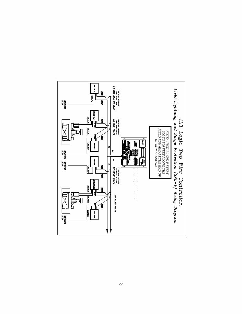
12. Semi/Manual/Program Clear, Rain Delay, Run 13. Programming of Logic Receivers / Diamond Settings 14. Receiver Programming Instructions 15. Receiver Number Identification Tags, “Do’s & Don’ts” 16. Rain OFF Wiring Instructions 17. Rain OFF Diagram 18. Wire Chart 19. Wire Chart 20. Common Field Wiring Example 21. Field Wire Example-Pump Start Relay 22. Field Lightning and Surge Protection Wiring Diagram
Installation and field wiring instructions. Read booklet completely before beginning installation. NOTICE: Before installation, receivers must all be programmed. See page 14 for receiver programming instructions
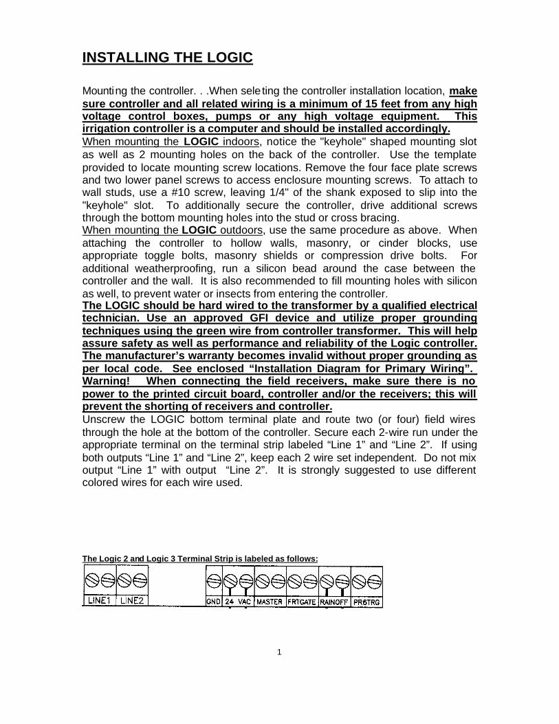
INSTALLING THE LOGIC Mounting the controller. . .When sele ting the controller installation location, make sure controller and all related wiring is a minimum of 15 feet from any high voltage control boxes, pumps or any high voltage equipment. This irrigation controller is a computer and should be installed accordingly. When mounting the LOGIC indoors, notice the "keyhole" shaped mounting slot as well as 2 mounting holes on the back of the controller. Use the template provided to locate mounting screw locations. Remove the four face plate screws and two lower panel screws to access enclosure mounting screws. To attach to wall studs, use a #10 screw, leaving 1/4" of the shank exposed to slip into the "keyhole" slot. To additionally secure the controller, drive additional screws through the bottom mounting holes into the stud or cross bracing. When mounting the LOGIC outdoors, use the same procedure as above. When attaching the controller to hollow walls, masonry, or cinder blocks, use appropriate toggle bolts, masonry shields or compression drive bolts. For additional weatherproofing, run a silicon bead around the case between the controller and the wall. It is also recommended to fill mounting holes with silicon as well, to prevent water or insects from entering the controller. The LOGIC should be hard wired to the transformer by a qualified electrical technician. Use an approved GFI device and utilize proper grounding techniques using the green wire from controller transformer. This will help assure safety as well as performance and reliability of the Logic controller. The manufacturer’s warranty becomes invalid without proper grounding as per local code. See enclosed “Installation Diagram for Primary Wiring”. Warning! When connecting the field receivers, make sure there is no power to the printed circuit board, controller and/or the receivers; this will prevent the shorting of receivers and controller. Unscrew the LOGIC bottom terminal plate and route two (or four) field wires through the hole at the bottom of the controller. Secure each 2-wire run under the appropriate terminal on the terminal strip labeled “Line 1” and “Line 2”. If using both outputs “Line 1” and “Line 2”, keep each 2 wire set independent. Do not mix output “Line 1” with output “Line 2”. It is strongly suggested to use different colored wires for each wire used. The Logic 2 and Logic 3 Terminal Strip is labeled as follows:
1
VALVE WIRING
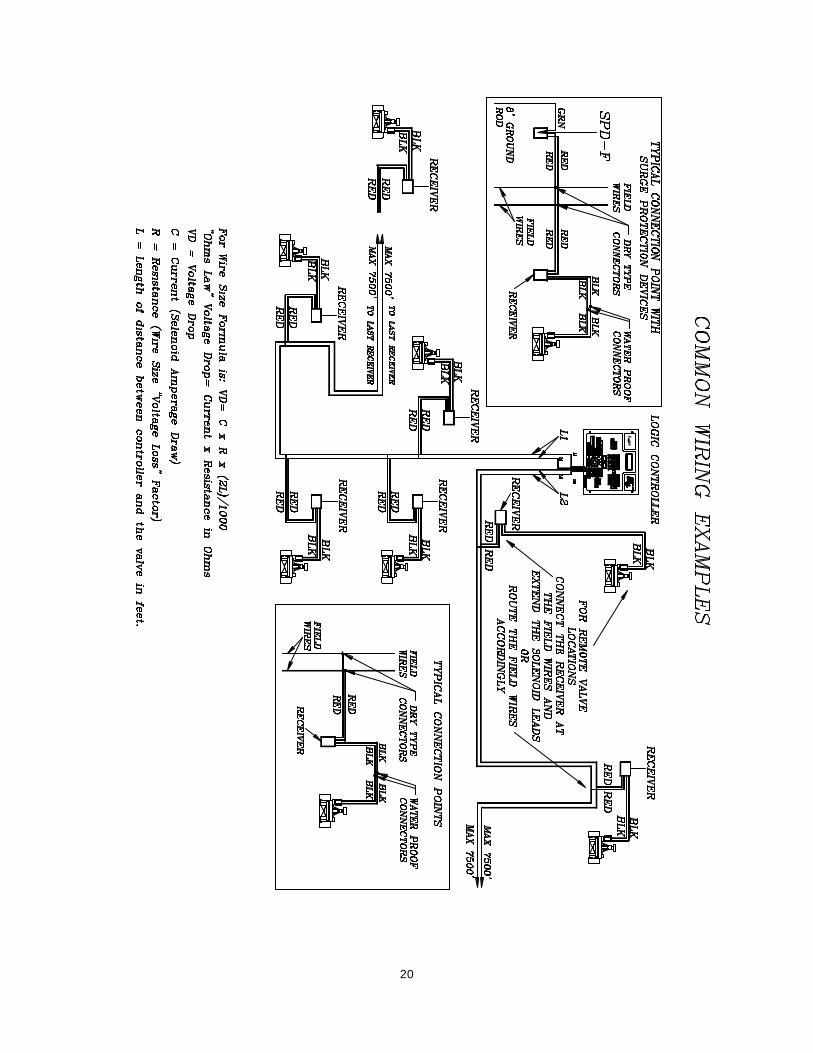
The field wiring from the controller to the receivers consists of either one or two, 2-wire runs, which connect, in series, to each valve location. Each 2-wire run is totally independent of the other relative to wire size requirements and the number of valves operating simultaneously. Both 2-wire runs receive and output the exact same information. The purpose of 2 independent 2 wire runs are for reducing the potential amount of “back tracking” when valves are located in more than one general direction from the controller. Theoretically, with the Logic controller located in the center of an irrigation project, one 2-wire run would go one direction and the other 2-wire run could go the other direction. “Line 1” is one 2-wire run; “Line 2” is the second available 2-wire run. The 2-wire runs start at the controller and end at the last receiver/valve for that wire run. Do not loop or make a complete connected circle. For the main 2-wire runs, it is very important to size the wire properly. Consideration for designing the proper wire size includes the total wire distance from controller to the farthest receiver and how many valves will be operating simultaneously. Wire size must be designed using Ohm’s law for any application. The field wiring should consist of one or two continuous main 2 wire runs starting at the controller terminal labeled “Line 1” or “Line 2” continuing to the last receiver/valve of that wire run. If using the dual output feature, use one continuous length of wire independently from each output “Line 1” and the second independent 2 wire run from “Line 2”. Every receiver is to be connected directly anywhere on one of your main two-wire continuous runs. Do not tee or branch the main two wire runs. To access remote valve(s), attach the two red receiver wires (one red wire to each field wire) of the main two wire run. Extend the black solenoid leads from the receiver and attach to the solenoid at the valve. The distance from a receiver to the solenoid is limited only by standard wire sizing/distance and voltage drop parameters. From the controller to the solenoid the voltage can not exceed 7 voltage loss. The last receiver installed is the end of the main two wire run. You may operate a maximum of four of the same numbered receivers or four valves maximum of any random numbered receivers at any one time. This will affect the wire size, as more power draw will be needed. (See wire-sizing guide.) Use the following formula when designing your wire size for each Logic 2 wire run. Consult attached wire charts to insure proper wire gage. Minimum wire size and type is 14 Ga. Always use direct bury, heavy jacket, solid core copper wire
.
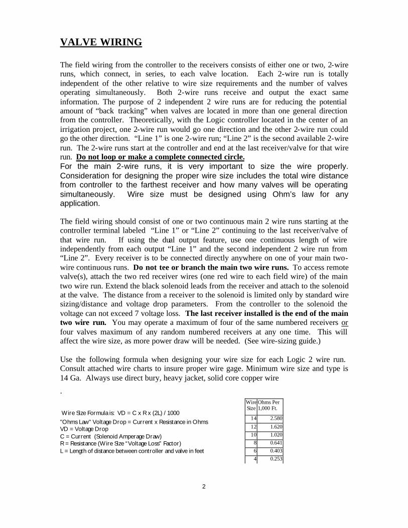
Wire Size Formula is: VD = C x R x (2L) / 1000 "Ohms Law" Voltage Drop = Current x Resistance in Ohms VD = Voltage Drop C = Current (Solenoid Amperage Draw) R = Resistance (Wire Size “Voltage Loss” Factor) L = Length of distance between controller and valve in feet
2
Wire Size
Ohms Per 1,000 Ft.
14 2.580
12 1.62010 1.020
8 0.6416 0.4034 0.253
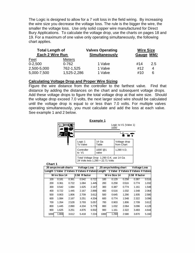
The Logic is designed to allow for a 7 volt loss in the field wiring. By increasing the wire size you decrease the voltage loss. The rule is the bigger the wire, the smaller the voltage loss. Use only solid copper wire manufactured for Direct Bury Applications. To calculate the voltage drop, use the charts on pages 18 and 19. For a maximum of one valve only operating simultaneously, the following chart applies.
Total Length of Valves Operating Wire Size Each 2 Wire Run Simultaneously Gauge MM2 Feet Meters 0-2,500 0-762 1 Valve #14 2.5 2,500-5,000 762-1,525 1 Valve #12 4 5,000-7,500 1,525-2,286 1 Valve #10 6 Calculating Voltage Drop and Proper Wire Sizing Figure the wire distance from the controller to the farthest valve. Find that distance by adding the distances on the chart and subsequent voltage drops. Add these voltage drops to figure the total voltage drop at that wire size. Should the voltage drop exceed 7.0 volts, the next larger sized wire should be calculated until the voltage drop is equal to or less than 7.0 volts. For multiple valves operating simultaneously, you must calculate and add the loss at each valve. See example 1 and 2 below.
Example 1
Chart 1
Logic to V1 (Valve 1) 1000́
Logic 1 To Valve
14 Ga Table
Voltage drop from Chart
Controller to V1
1000´@1 valve
1.290 V.D.
Total Voltage Drop 1.290 O.K. use 14 Ga 24 Volts less 1.290 = 22.71 Volts
CALENDAR ODD / EVEN
PRE WET / FERTIGATION
MASTER CLEAR
PROGRAM RECEIVER
FERTIGATION ON
MASTER ON
.35 amps inrush charts Voltage Loss .25 amps holding chart Voltage Loss
Length 1 Valve 2 Valves 3 Valves 4 Valves Length 1 Valve 2 Valves 3 Valves 4 Valves
Wire Size 14 2.58 R factor Wire Size 14 2.58 R factor
100 0.181 0.361 0.542 0.722 100 0.129 0.258 0.387 0.516200 0.361 0.722 1.084 1.445 200 0.258 0.516 0.774 1.032300 0.542 1.084 1.625 2.167 300 0.387 0.774 1.161 1.548400 0.722 1.445 2.167 2.890 400 0.516 1.032 1.548 2.064500 0.903 1.806 2.709 3.612 500 0.645 1.290 1.935 2.580600 1.084 2.167 3.251 4.334 600 0.774 1.548 2.322 3.096700 1.264 2.528 3.793 5.057 700 0.903 1.806 2.709 3.612800 1.445 2.890 4.334 5.779 800 1.032 2.064 3.096 4.128900 1.625 3.251 4.876 6.502 900 1.161 2.322 3.483 4.644
1000 1.806 3.612 5.418 7.224 1000 1.290 2.580 3.870 5.160
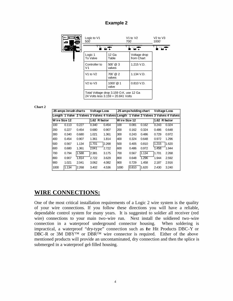
Example 2
Logic 1 To Valve
12 Ga Table
Voltage drop from Chart
Controller to V1
500´@ 3 valves
1.215 V.D.
V1 to V2 700´@ 2 valves
1.134 V.D.
Total Voltage drop 3.159 O.K. use 12 Ga 24 Volts less 3.159 = 20.841 Volts
V2 to V3 1000´@ 1 valve
0.810 V.D.
Logic to V1 V1 to V2 V2 to V3 500́ 700́ 1000´
Chart 2
.35 amps inrush charts Voltage Loss .25 amps holding chart Voltage Loss Length 1 Valve 2 Valves 3 Valves 4 Valves Length 1 Valve 2 Valves 3 Valves 4 Valves
Wire Size 12 1.62 R factor Wire Size 12 1.62 R factor 100 0.113 0.227 0.340 0.454 100 0.081 0.162 0.243 0.324
200 0.227 0.454 0.680 0.907 200 0.162 0.324 0.486 0.648 300 0.340 0.680 1.021 1.361 300 0.243 0.486 0.729 0.972 400 0.454 0.907 1.361 1.814 400 0.324 0.648 0.972 1.296
500 0.567 1.134 1.701 2.268 500 0.405 0.810 1.215 1.620 600 0.680 1.361 2.041 2.722 600 0.486 0.972 1.458 1.944
700 0.794 1.588 2.381 3.175 700 0.567 1.134 1.701 2.268
800 0.907 1.814 2.722 3.629 800 0.648 1.296 1.944 2.592 900 1.021 2.041 3.062 4.082 900 0.729 1.458 2.187 2.916
1000 1.134 2.268 3.402 4.536 1000 0.810 1.620 2.430 3.240
WIRE CONNECTIONS: One of the most critical installation requirements of a Logic 2 wire system is the quality of your wire connections. If you follow these directions you will have a reliable, dependable control system for many years. It is suggested to soldier all receiver (red wire) connections to your main two-wire run. Next install the soldiered two-wire connection in a waterproof underground connector housing. When soldering is impractical, a waterproof “dry-type” connection such as the Hit Products DBC-Y or DBC-R or 3M DBY™ or DBR™ wire connector is required. Either of the above mentioned products will provide an uncontaminated, dry connection and then the splice is submerged in a waterproof gel- filled housing.
4
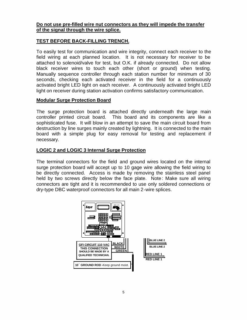
Do not use pre-filled wire nut connectors as they will impede the transfer of the signal through the wire splice. TEST BEFORE BACK-FILLING TRENCH. To easily test for communication and wire integrity, connect each receiver to the field wiring at each planned location. It is not necessary for receiver to be attached to solenoid/valve for test, but O.K. if already connected. Do not allow black receiver wires to touch each other (short or ground) when testing. Manually sequence controller through each station number for minimum of 30 seconds, checking each activated receiver in the field for a continuously activated bright LED light on each receiver. A continuously activated bright LED light on receiver during station activation confirms satisfactory communication. Modular Surge Protection Board The surge protection board is attached directly underneath the large main controller printed circuit board. This board and its components are like a sophisticated fuse. It will blow in an attempt to save the main circuit board from destruction by line surges mainly created by lightning. It is connected to the main board with a simple plug for easy removal for testing and replacement if necessary. LOGIC 2 and LOGIC 3 Internal Surge Protection The terminal connectors for the field and ground wires located on the internal surge protection board will accept up to 10 gage wire allowing the field wiring to be directly connected. Access is made by removing the stainless steel panel held by two screws directly below the face plate. Note : Make sure all wiring connectors are tight and it is recommended to use only soldered connections or dry-type DBC waterproof connectors for all main 2-wire splices.
CALENDAR ODD / EVEN
PRE WET / FERTIGATION
MASTER CLEAR
PROGRAM RECEIVER
FERTIGATION ON
MASTER ON
BLACK WHITE GREEN
10´ GROUND ROD -Keep ground moist.
? ?
? ?
GFI CIRCUIT 110 VAC THIS CONNECTION
SHOULD BE MADE BY A QUALIFIED TECHNICIAN. RED LINE 1
RED LINE 1
BLUE LINE 2 BLUE LINE 2
5

Controller Lightning Protection It is recommended that, in environments where either power surges or direct lightning strikes are possible, the following installation of grounding protection be followed on the primary input power supply. Every Logic controller is supplied with a heavy duty-surge protection kit that will protect your controller against power surges on the primary side. To activate, it must be installed per local grounding codes. In case a power surge exceeds the limitations of the board, the surge protection kit will blow and a new surge protection replacement kit can easily be installed without the need to replace the whole controller (Part #L-SPD-F). Field Wiring/Receiver Lightning Protection As with any electronic equipment buried in the field, it is recommended to use surge protection devices every 300 – 500 feet along the main 2 wire run and at the end. These model #L-SPD-F, field surge protection kits are to be installed at same convenient location as any receiver. Each L-SPD-F does require a grounding rod-not included with the Hit Products model #L-SPD-F. Attach the green #L-SPD-F wire to the grounding rod. See diagram on page 22.
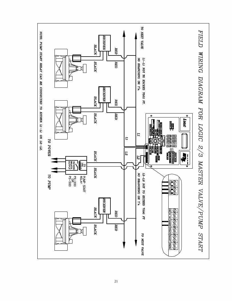
Pump Start Relay When using a pump start relay, the relay shall be a 24 VAC coil with a maximum inrush of .35 amps and holding .25 amps. The relay will act as a slave to the magnetic relay to control the pump motor. You can use up to a 5hp Hit Products pump start relay attached directly to the relay terminal. See diagram on page 21.
Fertigation The controller is fitted with a separate relay to operate a 24VAC system with a maximum inrush of .35 amps and holding .25 amps at 24VAC, for application of fertilizer or other material injection systems. A slave relay should be used to operate any auxiliary pumps or injection systems exceeding the above power requirements. Read This First! The LOGIC Controllers are so easy to program because the four sets of black up/down buttons correspond to whatever is directly above them in the display. You can toggle between ON and OFF, set hours, minutes, and seconds, or even select program numbers, valve numbers, and start times simply by using these up/down buttons located directly under their functions. For more advanced special feature functions look to right of up/down buttons. These advanced features may be accessed by having dial in corresponding number to that number in box to the left of function. **************************************************************************************“NOTE”
When you first install your LOGIC 2 or LOGIC 3 controller, press Master Clear to clear all possible information stored in the unit. Put dial in position 10, Press top right Up/Down key under “CLR” OFF. Push Advanced Feature button. Controller will automatically clear ALL programmable data except current date and time.
6

FEATURES LOGIC 2 LOGIC 3
Stations Available 1-42 1-128 Programs Available 8 16
Run Time Per Station 0-10 hours, 59 min. Max. 0-10 hours, 59 min. Max. Programs 5 & 6 0-59 min., 59 sec. 0-59 min., 59 sec. Calendar 0-28 days Max.,ODD/EVEN 0-28 days Max.,ODD/EVEN
Water Budget 0-250% 0-250% Rain OFF Days 0-31 days Max. 0-31 days Max.
Pause 0-59 sec. 0-59 sec. PROGRAMMING THE LOGIC 2 and LOGIC 3 CONTROLLERS The Logic controller is a very simple controller to program. It has built in features and automatic programming that will be explained throughout these instructions. Please read the entire operational manual before starting to program the Logic controller. The controller programming consists of 8 buttons to control the display, a twelve position rotary switch and a special function key for more special options. The 8 buttons that control the display are located directly below the portion of the display they control. Each set (two buttons) of buttons operates the display up or down for ease of getting to the function, number, valve or time desired. For ease of explanation, the following terminology will be used throughout these instructions. The set of buttons to the far left will be button set 1, directly right of these will be set 2, directly right of set 2 will be set 3 and the last set or far right set will be set 4, the special feature button in the upper right of the control panel, will be referred to as set 5 . The main rotary dial has 12 positions just like the numbered hour positions on a clock 1-12. The rotary switch consists of the following positions and functions:
Position 1 CurrentDate/ Current Time
Current Date: Set today’s Date, use set 2 to set month, use set 3 to set day of month, use set 4 to set year, i.e.: 5/30/01 Current Time: Set time of day, use set 1 to change display from date to time, use set 2 to set hour (this will set A.M. or P.M.), use set 3 to set minutes, use set 4 to “Zero out” seconds.
Position 2
Pre Wet – Special Feature Button Fertigation – Special Feature Button
Set Valve Run Times: Use set 1 to choose the program, use set 2 to choose the valve number, use set 3 to set hours, use set 4 to set minutes. Input the total irrigation run time desired for each valve, including pre wet and fertigation time.
7
Valve Run Times

Pre Wet and Fertigation option: Press set 5, the display will now be the same, except with the following changes, a “P” will show in front of Hours. Use set 3 or 4 to set amount of hours and minutes for the pre-wet time. Press set 5, again the display will stay the same except for a “F’ that will show in front of hours, use sets 3 or 4 to set the amount of hours and minutes for fertigation. NOTE: At no time will the controller permit the total time of pre-wet and fertigation to exceed the total run time programmed. No pre-wet run times need to be programmed in order to run the fertigation mode. NOTE: Programs 5 and 6 can only be set in minutes and seconds, as all other programs can be set in hours and minutes. The maximum run times can be set from 1 minute to 10 hours and 59 minutes on all programs except 5 and 6, which can be set for a minimum of 10 seconds to a maximum of 59 minutes and 59 seconds. With the water budget feature (position 8) these run times can be increased or decreased from 0% to 250% in 5% increments. Definitions: Pre-wet will run concurrently at the start of the valve run time. Fertigation will start at the conclusion of the programmed pre wet cycle and will automatically activate the fertigation relay (terminals located on the bottom of the controller board). If only fertigation time is programmed and no pre-wet time is programmed, fertigation will start at the commencement of the valve run time programmed. This relay will remain activated for as long as the fertigation is programmed. If the total valve run time is 15 minutes, pre wet for 3 minutes and fertigation for 5 minutes, then there will be 7 minutes remaining of valve run time after the fertigation cycle ends. Note: A maximum of any 4 receivers/valves (any combination) may be operated simultaneously. Wire size must be designed for simultaneous multi-valve operation on same 2 wire run.
Position 3 Pause
Pause: Use set 1 to choose the program, use set 2 or 3 to set desired time, use set 4 to turn master valve or pump start function ON or OFF during pause function. Definitions: Pause: Amount of time delay between sequential valve openings in a program Master: Master ON will keep the master valve or pump relay ON during pause. Master OFF: Will turn master valve or pump relay OFF during pause. Note: In order for this option to function, the master valve must be activated (see position 8 below) for that specific program.
8
Position 4 Start Time To set start times, use set 1 to choose the desired program, use set 2 to choose the start number, (always use start 1 for the first start time after midnight and so on through start 8 (Logic II) start 16 (Logic III) use set 3 to set the hour of the start time, use set 4 to set the minutes of the start time. Note: The start time is part of the first leg of a preprogrammed function called “Diamond Settings” Refer to Diamond settings at the end of this programming guide for full details.
Position 5 Total Run Time To review the total run time in a specific program, use set 1 to choose the program number. The total run time of that specific program is shown in the lower right hand position of the display. You can review the water budget setting along with the total run time in this position. If the water budget is changed from the default of 100%, the total run times will change in this position, but in position 2, the valve run times will stay as inputted. The actual running of the valve is determined by the input in position 2 multiplied by the water budget setting in position 8. To review the numbered day of the calendar the controller is currently on, use set 1 to choose the program desired. The day of the calendar will be displayed directly right of the word “DAY” in the upper display. You can change the day of the calendar by using set 3 buttons. This will or can bring all days of all programs to the same day for calendar purposes. Note: By adjusting the budget up or down (0% to 250%) it will change the total run time. See position 8 for further discussion. The budget is the second leg of the Diamond Setting.
Position 6 Calendar The calendar is the third leg of the Diamond Setting. After programming the run times and the start times, the calendar will automatically establish the minimum calendar period. You can manually change the calendar to any desired period, longer than the minimum “Auto-calendar” period, but not shorter. By pressing set 1 to select the program, press set 2 to change the number of days desired in the calendar, (if the total run time exceeds one day, the calendar can not be set backwards. Press set 3 to review the days of the calendar. By pressing set 3 repetitively, the display above set 4 will show one of the following events: Strt (start), run or off for each day of the calendar. Note: The calendar automatically resets all programs to Day 1, today, for all programs when “Master Clear” is activated. The calendar automatically resets to Day 1, today, whenever a “Program Clear” function is activated for that specific program. The calendar automatically resets to today, Day 1, when any value in “Calendar” (Position 6) is changed. The calendar can be manually changed to any day being today in Position 5, “Total Run Time”. Day value has to be equal to or less than “calendar” number of days.
9
Definitions: Start: This is the day of the calendar that the program will start. This will be automatically set upon initial programming or set by the user. This is day 1 of the calendar, the day you set up the calendar or programmed the program or let the auto-calendar set up the calendar. Run: The total run time of the program has carried over into the second or more days and the program will be running these days to complete. Off: The user has programmed in additional days that the program will not be active. Odd/Even: May be accessed by pressing Feature Key #6. Runtime must not go beyond 11:59p.m. Note: The number of days that the calendar automatically sets up is determined as follows: The number of hours from 12:00 midnight to the first start time plus the total run time, divided by 24 hours will equal the number of calendar days. Example : If a start time is 8:00am, then the first calculation would be 8 hours plus a total run time of 56 hours for a grand total of 64 hours, divided by 24 hours would equal a 2.67 day calendar, the display would show a 3 day calendar, as follows, day 1 STRT, day 2 RUN, and day 3 RUN. If you wanted to irrigate every 4th day, use set 2 to expand the calendar from 3 days to 4 days, day 4 wo uld show OFF. Another example would be to run a program Monday, Wednesday and Friday. The auto-calendar would set up as 1 day, set the calendar to 7 days. If Tuesday were the day you set up the program, this would be day 1 of the calendar. Therefore you would change day 1 from STRT to Off, and then set up day 2 (Wed.) as a STRT (start) and day 3 off, day 4 STRT (Fri), day 5 off, day 6 off and day 7(Mon) STRT. Note: To further understand the Diamond setting for calendar, read the Diamond setting on page 13.
Position 7 Looping Program 6
Any valve run times and start times set in program 6 can be looped if desired. There must be individual run times for each valve and one start time in program 6 for looping to be activated. Use set 3 and set 4 to establish the total amount of loop time desired. Use set 2 to turn looping feature ON or OFF. Hints for using Looping: Looping will run a program continuously for the amount of time set in position 7 looping. For example: If looping is set for 6 hours and the start time is 8:00 am, program 6 will start at 8:00 am and run for 6 hours. A new lawn can be irrigated for 5 minutes every hour by doing the following. Valves 1, 2 and 3 operate the new lawn, set run times for 5 minutes each on valves 1, 2 and 3, then go to a valve that is not being used and set run time for 45 minutes. You want to irrigate from 10 am until 5 pm. Set start time for program 6 at 10:00 am and go to position 7, set loop for 7 hours and turn looping ON. The program will start at 10 am and run va lve 1 for 5 minutes, then valve 2 for 5 minutes and then valve 3 for 5 minutes and then the valve that is not being used for 45 minutes and then back to valve 1 and so on until 7 hours runs out, which will be 5:00 PM. Caution! If operating with a pump, the 45 minutes will cause “Dead Heading” on the pump and may damage the pump or pipelines
10
Note: Program 6 can be sensor activated, such as a temperature sensor. The terminals for remote operation are located on the terminal board and marked pr6trg (program 6 trigger). Program the amount of run times per valve in program 6, do not put in a start time, make sure the program is ON in position 8 and whether or not the master should run with program 6. Program the amount of loop time in position 7. The contacts on the board are “Normally Open”, when the remote sensor activates and closes the contacts for more than 30 seconds, program 6 will operate for the looping time programmed. If for any reason the remote sensor contact opens during the looping cycle, the looping cycle will continue until the programmed time is completed. The sensor must open and close the contacts to operate the looping cycle a second time. If, for any reason, the contacts open and close during the preprogrammed length of looping, the looping program will reset at that time and start over again.
Position 8 Program/Master Valves ON/OFF
Pump Start
Water Budget % Use set 1 to choose the program desired, use set 2 to turn a program ON or OFF (a fully programmed program can be disabled by the this function) use set 3 to turn the master valve or pump start ON or OFF during the program running, use set 4 to increase or decrease the budget feature of the program. (The amount of time in position 2 will not change in the display but the actual run time will be increased or decreased by the amount of budget %). The new “water budgeted” run times can be viewed in position 5. Note: The water budget is the fourth leg of the Diamond Settings (see page 13 for more on the Diamond Settings).
Position 9
Use set 1 to set run time in minutes, use set 2 to set run time of seconds for test cycle, and use set 4 to turn ON or OFF test cycle. The controller will immediately run each valve in sequence for the predetermined run time for visual review of the systems operation. Note: The pause setting in position 3 for program 1 will determined the amount of pause between stations during the test cycle operation.
11
Test Cycle
Position 10 Semi/ Manual/ Program Clear
Master Clear – Special Feature Button Semi- use set 1 to choose the program you want to activate for one cycle, use set 2 to activate that program ON. At the conclusion, the controller will revert to automatic after 30 minutes, without putting the rotary switch back to "Run". Manual — Press set 3 to activate manual mode, use set 1 to choose the specific valve number to be operated manually for a predetermined time, use set 2 to set amount of hours to run, use set 3 to set amount of minutes, use set 4 to tell the controller whether or not you want the master valve or the pump start on during this manual operation. Valve will immediately be activated for that period of time. At the conclusion, the controller will go back to “RUN” mode without turning the rotary switch back to the “RUN” position. You can activate up to 4 valves at the same time in manual mode. Note: In running semi or running a valve manually, position 8 will dictate whether the master valve or the pump start will run with that program or valves(s). Program Clear/Program: Use set 4 to choose program clear, use set 1 to choose the program that you desire to clear all the information from, use set 4 to answer yes. Note: By clearing the program all information for that program is deleted. Master Clear will clear all the information in the controller by way of the following: Turn rotary switch to position 10, press set 4, and then press the special function set 5, “Master Clear”. All programming data in all programs will be deleted. Only the current time and date will remain. Position 11
To set days of delay (controller will not run for the number of days set) press set 1 for the number of days of delay, remember the new day starts at midnight. To turn controller ON or OFF press set 4 to turn controller ON or OFF. In the OFF position, controller will keep time but no output will be made to activate valves on any program. See pages 16 and 17.
Position 12 Program Receiver – Special Feature Button
In the run position controller will execute all that you have instructed it to do. The controller can be programmed while running an automatic program. While programming, the operation will stop; after programming turn dial back to position 12 (Run). If today is a start day the controller will resume operation. If it is a run day, the controller will wait until the next start time or start day. Note: If position 10 is used and left in position 10, the controller will automatically revert to position 12 (Run) after 30 minutes and resume any automatic programmed functions.
12
Rain Delay Auto/On/Off
Run
DIAMOND SETTINGS The DS as we call it, is an automatic calendar setting after run times and start times are entered. The DS will set the minimum days of the irrigation calendar. This is to protect against overlapping within a program. After initial programming of the Logic, run times and start times, the DS will not allow you to enter additional run times or increase the budget so that it will exceed the current calendar days set. If you are unable to increase run times, check your “total run time” in position 5. If the “total run time” for that program is close to the number of current calendar days for that program you may have to increase the number of calendar days to get the controller to accept increased run times, increased water budget or adding more valves with run times to that program. The same is true of increasing the water budget, the calendar may have to be extended to accommodate the extended run times to allow the program to complete its cycle.
The DS sets the calendar automatically as follows. The start time entered is calculated as to how many hours past 12 midnight it is, for example an 8AM start time would be 8 hours from midnight or the start of that day, then the DS looks at total run times including pause time and adds the time from midnight to the start time together. If the total time exceeds 24 hours the calendar is set for two days, if the total time exceeds 48 hours the calendar is set to a three-day calendar and so on. The first day will be set as a STRT day (Start) the following day will be “run” days. The day you programmed this program, automatically becomes day 1 of the calendar, for example a three-day calendar programmed on Monday would look like the following:
Day 1 STRT would be Monday Day 2 RUN would be Tuesday Day 3 RUN would be Wednesday Day 1 STRT would be Thursday Day 2 RUN would be Friday And so on; please note that any calendar not divisible by 7 will run on different days of the week as the year progresses. If the above example were changed to a five-day calendar the days 4 and 5 would show OFF. It is important to remember if the total run time of a program is under 23 hours and 59 minutes, the DS automatically sets the calendar to one day. Even if the start time is set to allow the program to run past midnight into the next day. The same is true if multiple start times are used in the same program and the total runtime of the program multiplied by the number of start times is under 23 hours and 59 minutes. The DS wi ll not allow multiple start times that total more than 23 hours and 59 minutes.
13
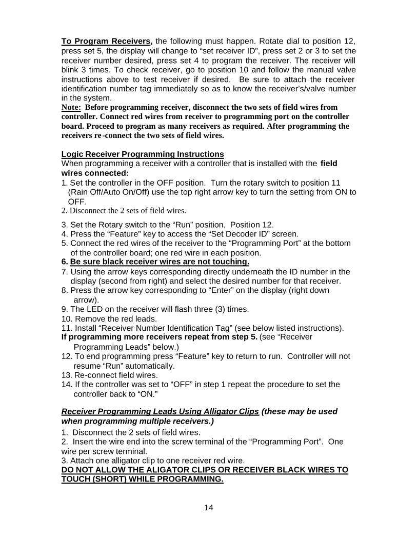
To Program Receivers, the following must happen. Rotate dial to position 12, press set 5, the display will change to “set receiver ID”, press set 2 or 3 to set the receiver number desired, press set 4 to program the receiver. The receiver will blink 3 times. To check receiver, go to position 10 and follow the manual valve instructions above to test receiver if desired. Be sure to attach the receiver identification number tag immediately so as to know the receiver’s/valve number in the system. Note: Before programming receiver, disconnect the two sets of field wires from controller. Connect red wires from receiver to programming port on the controller board. Proceed to program as many receivers as required. After programming the receivers re -connect the two sets of field wires. Logic Receiver Programming Instructions When programming a receiver with a controller that is installed with the field wires connected: 1. Set the controller in the OFF position. Turn the rotary switch to position 11
(Rain Off/Auto On/Off) use the top right arrow key to turn the setting from ON to OFF.
2. Disconnect the 2 sets of field wires.
3. Set the Rotary switch to the “Run” position. Position 12. 4. Press the “Feature” key to access the “Set Decoder ID” screen. 5. Connect the red wires of the receiver to the “Programming Port” at the bottom
of the controller board; one red wire in each position. 6. Be sure black receiver wires are not touching. 7. Using the arrow keys corresponding directly underneath the ID number in the
display (second from right) and select the desired number for that receiver. 8. Press the arrow key corresponding to “Enter” on the display (right down
arrow). 9. The LED on the receiver will flash three (3) times. 10. Remove the red leads. 11. Install “Receiver Number Identification Tag” (see below listed instructions). If programming more receivers repeat from step 5. (see “Receiver
Programming Leads” below.) 12. To end programming press “Feature” key to return to run. Controller will not
resume “Run” automatically. 13. Re-connect field wires. 14. If the controller was set to “OFF” in step 1 repeat the procedure to set the
controller back to “ON.”
Receiver Programming Leads Using Alligator Clips (these may be used when programming multiple receivers.) 1. Disconnect the 2 sets of field wires. 2. Insert the wire end into the screw terminal of the “Programming Port”. One wire per screw terminal. 3. Attach one alligator clip to one receiver red wire. DO NOT ALLOW THE ALIGATOR CLIPS OR RECEIVER BLACK WIRES TO TOUCH (SHORT) WHILE PROGRAMMING.
14
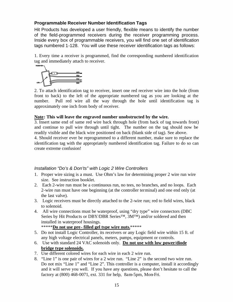
Programmable Receiver Number Identification Tags Hit Products has developed a user friendly, flexible means to identify the number of the field-programmed receivers during the receiver programming process. Inside every box of programmable receivers, you will find one set of identification tags numbered 1-128. You will use these receiver identification tags as follows: 1. Every time a receiver is programmed, find the corresponding numbered identification tag and immediately attach to receiver.
2. To attach identification tag to receiver, insert one red receiver wire into the hole (from front to back) to the left of the appropriate numbered tag as you are looking at the number. Pull red wire all the way through the hole until identification tag is approximately one inch from body of receiver. Note: This will leave the engraved number unobstructed by the wire. 3. Insert same end of same red wire back through hole (from back of tag towards front) and continue to pull wire through until tight. The number on the tag should now be readily visible and the black wire positioned on back (blank side of tag). See above. 4. Should receiver ever be reprogrammed to a different number, make sure to replace the identification tag with the appropriately numbered identification tag. Failure to do so can create extreme confusion!
Installation “Do’s & Don’ts” with Logic 2 Wire Controllers 1. Proper wire sizing is a must. Use Ohm’s law for determining proper 2 wire run wire
size. See instruction booklet. 2. Each 2-wire run must be a continuous run, no tees, no branches, and no loops. Each
2-wire run must have one beginning (at the controller terminal) and one end only (at the last valve).
3. Logic receivers must be directly attached to the 2-wire run; red to field wires, black to solenoid.
4. All wire connections must be waterproof, using “dry type” wire connectors (DBC Series by Hit Products or DBY/DBR Series™, 3M™) and/or soldered and then installed in waterproof housings. *****Do not use pre- filled gel type wire nuts.*****
5. Do not install Logic Controller, its receivers or any Logic field wire within 15 ft. of any high voltage electrical panels, meters, pumps, equipment or controls.
6. Use with standard 24 VAC solenoids only. Do not use with low power/diode bridge type solenoids.
7. Use different colored wires for each wire in each 2 wire run. 8. “Line 1” is one pair of wires for a 2 wire run. “Line 2” is the second two wire run.
Do not mix “Line 1” and “Line 2”. This controller is a computer, install it accordingly and it will serve you well. If you have any questions, please don’t hesitate to call the factory at (800) 468-0071, ext. 331 for help, 8am-5pm, Mon-Fri.
15
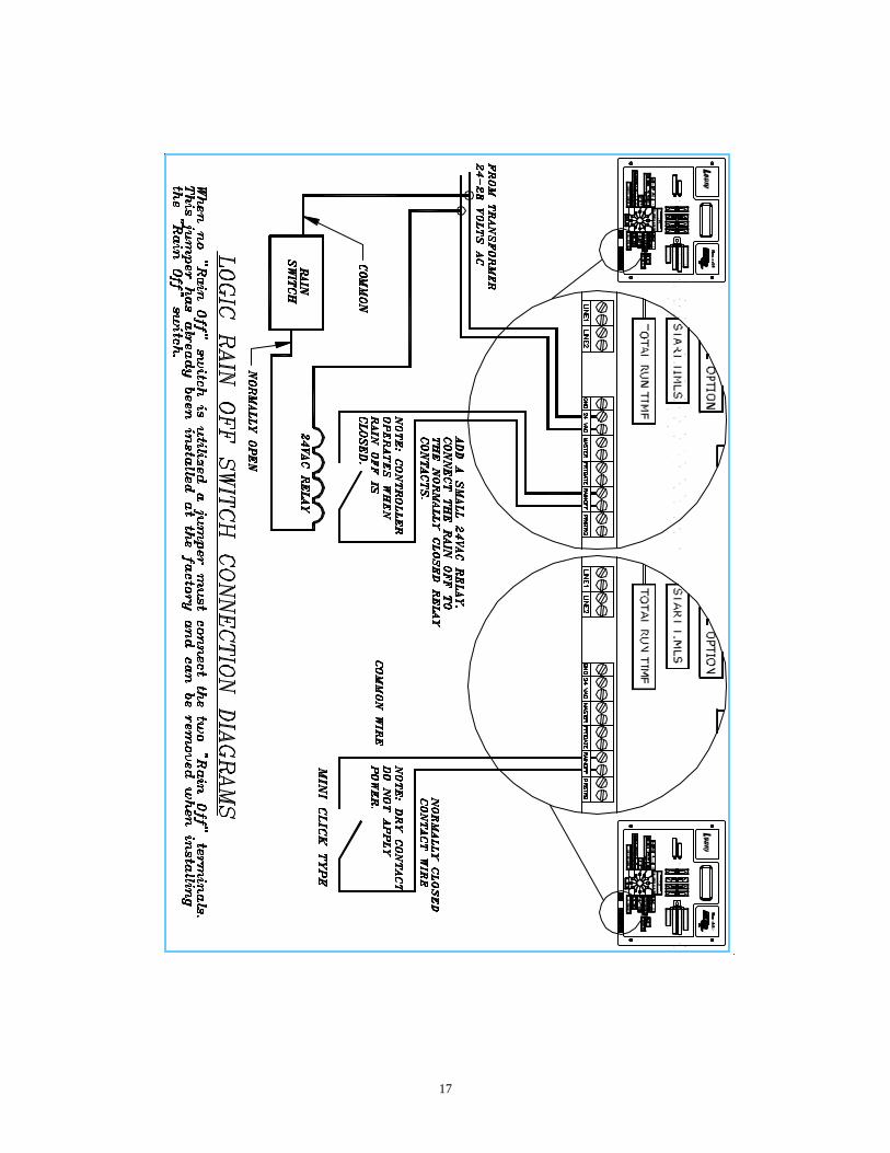
Logic “RAIN OFF” Switch Wiring Instructions Location: The rain off terminal is located on the bottom right of the Controller board labeled “RAIN OFF”. These two terminal screws must be jumped with a wire to close the circuit and enable normal operation. This jumper wire is factory installed. It is to be removed if utilizing a “Rain Off” switch. Function: This is a normally closed, dry contact circuit. When the circuit is open the unit will display RAIN and turn off all station output. When the contact is closed the program will resume running where it would have been at that time during normal operating mode. Important Note: Do not apply live power directly to these contacts. Tips: Problem example 1: When using a rain off switch at distances from the controller, the controller sometimes does not receive the on/off signal from the sensor. Remedy: A) Relocate the sensor near the controller. B) Use a larger wire size to eliminate the resistance from the long distance of the run. C) For sensors requiring an isolation relay, Example: Rain guard type (see drawing). Relocate the relay to inside the Logic controller cabinet. The sensor itself may be at a remote location. Problem example 2: The LCD display alternates from the normal text to the word RAIN. This is caused from application of 24VAC to the sensor input. Note: 24VAC will not permanently damage the sensor, but proper wiring must be completed to restore normal operation. Remedy: This input is a dry contact only. A single wire from one terminal screw to a normally closed contact with a single return wire to the second terminal is required. Use care that neither wire is connected to the common or other power line. When acquiring a relay check the schematic that the actuator/coil is isolated from the contacts in the output section (no common connections are made internally). Most solid-state block relays have a Triac connected to the common internally and are not suitable for this application. Suggested 24VAC relays are: Omron LY2-AC24, Potter & Brumfield KHAU-17A11-24, NTE /Mauser 526-R11A10-24. Another source for relays (24VAC Coil, DPDT/SPDT contacts) is your local Radio Shack store.
P.O. Box 929, 556 S. Mirage Avenue
Lindsay, CA 93247 For Technical Assistance: 800-468-0071 ext. 331
16
CA
LE
ND
AR
O
DD
/
E
VE
N
PR
E
WE
T
/
FE
RT
IG
AT
IO
N
MA
ST
ER
C
LE
AR
PR
OG
RA
M
RE
CE
IV
ER
FE
RT
IG
AT
IO
N
ON
MA
ST
ER
O
N
CA
LE
ND
AR
O
DD
/
E
VE
N
PR
E
WE
T
/
FE
RT
IG
AT
IO
N
MA
ST
ER
C
LE
AR
PR
OG
RA
M
RE
CE
IV
ER
FE
RT
IG
AT
IO
N
ON
MA
ST
ER
O
N
17
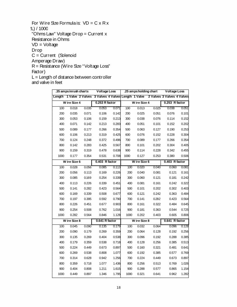
For Wire Size Formula is: VD = C x R x (2L) / 1000
"Ohms Law" Voltage Drop = Current x Resistance in Ohms VD = Voltage Drop C = Current (Solenoid Amperage Draw) R = Resistance (Wire Size “Voltage Loss” Factor) L = Length of distance between controller and valve in feet
.35 amps inrush charts Voltage Loss .25 amps holding chart Voltage Loss
Length 1 Valve 2 Valves 3 Valves 4 Valves Length 1 Valve 2 Valves 3 Valves 4 Valves
Wire Size 4 0.253 R factor Wire Size 4 0.253 R factor
100 0.018 0.035 0.053 0.071 100 0.013 0.025 0.038 0.051
200 0.035 0.071 0.106 0.142 200 0.025 0.051 0.076 0.101
300 0.053 0.106 0.159 0.213 300 0.038 0.076 0.114 0.152
400 0.071 0.142 0.213 0.283 400 0.051 0.101 0.152 0.202
500 0.089 0.177 0.266 0.354 500 0.063 0.127 0.190 0.253
600 0.106 0.213 0.319 0.425 600 0.076 0.152 0.228 0.304
700 0.124 0.248 0.372 0.496 700 0.089 0.177 0.266 0.354
800 0.142 0.283 0.425 0.567 800 0.101 0.202 0.304 0.405
900 0.159 0.319 0.478 0.638 900 0.114 0.228 0.342 0.455
1000 0.177 0.354 0.531 0.708 1000 0.127 0.253 0.380 0.506
Wire Size 6 0.403 R factor Wire Size 6 0.403 R factor
100 0.028 0.056 0.085 0.113 100 0.020 0.040 0.060 0.081
200 0.056 0.113 0.169 0.226 200 0.040 0.081 0.121 0.161
300 0.085 0.169 0.254 0.339 300 0.060 0.121 0.181 0.242
400 0.113 0.226 0.339 0.451 400 0.081 0.161 0.242 0.322
500 0.141 0.282 0.423 0.564 500 0.101 0.202 0.302 0.403
600 0.169 0.339 0.508 0.677 600 0.121 0.242 0.363 0.484
700 0.197 0.395 0.592 0.790 700 0.141 0.282 0.423 0.564
800 0.226 0.451 0.677 0.903 800 0.161 0.322 0.484 0.645
900 0.254 0.508 0.762 1.016 900 0.181 0.363 0.544 0.725
1000 0.282 0.564 0.846 1.128 1000 0.202 0.403 0.605 0.806
Wire Size 8 0.641 R factor Wire Size 8 0.641 R factor
100 0.045 0.090 0.135 0.179 100 0.032 0.064 0.096 0.128
200 0.090 0.179 0.269 0.359 200 0.064 0.128 0.192 0.256
300 0.135 0.269 0.404 0.538 300 0.096 0.192 0.288 0.385
400 0.179 0.359 0.538 0.718 400 0.128 0.256 0.385 0.513
500 0.224 0.449 0.673 0.897 500 0.160 0.321 0.481 0.641
600 0.269 0.538 0.808 1.077 600 0.192 0.385 0.577 0.769
700 0.314 0.628 0.942 1.256 700 0.224 0.449 0.673 0.897
800 0.359 0.718 1.077 1.436 800 0.256 0.513 0.769 1.026
900 0.404 0.808 1.211 1.615 900 0.288 0.577 0.865 1.154
1000 0.449 0.897 1.346 1.795 1000 0.321 0.641 0.962 1.282
18
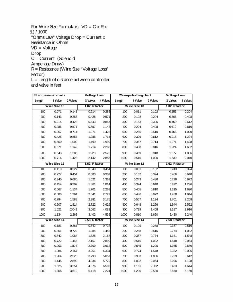
For Wire Size Formula is: VD = C x R x
(2L) / 1000 "Ohms Law" Voltage Drop = Current x Resistance in Ohms VD = Voltage Drop C = Current (Solenoid Amperage Draw) R = Resistance (Wire Size “Voltage Loss” Factor) L = Length of distance between controller and valve in feet
19
.35 amps inrush charts Voltage Loss .25 amps holding chart Voltage Loss
Length 1 Valve 2 Valves 3 Valves 4 Valves Length 1 Valve 2 Valves 3 Valves 4 Valves
Wire Size 10 1.02 R factor Wire Size 10 1.02 R factor
100 0.071 0.143 0.214 0.286 100 0.051 0.102 0.153 0.204
200 0.143 0.286 0.428 0.571 200 0.102 0.204 0.306 0.408
300 0.214 0.428 0.643 0.857 300 0.153 0.306 0.459 0.612
400 0.286 0.571 0.857 1.142 400 0.204 0.408 0.612 0.816
500 0.357 0.714 1.071 1.428 500 0.255 0.510 0.765 1.020
600 0.428 0.857 1.285 1.714 600 0.306 0.612 0.918 1.224
700 0.500 1.000 1.499 1.999 700 0.357 0.714 1.071 1.428
800 0.571 1.142 1.714 2.285 800 0.408 0.816 1.224 1.632
900 0.643 1.285 1.928 2.570 900 0.459 0.918 1.377 1.836
1000 0.714 1.428 2.142 2.856 1000 0.510 1.020 1.530 2.040
Wire Size 12 1.62 R factor Wire Size 12 1.62 R factor
100 0.113 0.227 0.340 0.454 100 0.081 0.162 0.243 0.324
200 0.227 0.454 0.680 0.907 200 0.162 0.324 0.486 0.648
300 0.340 0.680 1.021 1.361 300 0.243 0.486 0.729 0.972
400 0.454 0.907 1.361 1.814 400 0.324 0.648 0.972 1.296
500 0.567 1.134 1.701 2.268 500 0.405 0.810 1.215 1.620
600 0.680 1.361 2.041 2.722 600 0.486 0.972 1.458 1.944
700 0.794 1.588 2.381 3.175 700 0.567 1.134 1.701 2.268
800 0.907 1.814 2.722 3.629 800 0.648 1.296 1.944 2.592
900 1.021 2.041 3.062 4.082 900 0.729 1.458 2.187 2.916
1000 1.134 2.268 3.402 4.536 1000 0.810 1.620 2.430 3.240
Wire Size 14 2.58 R factor Wire Size 14 2.58 R factor
100 0.181 0.361 0.542 0.722 100 0.129 0.258 0.387 0.516
200 0.361 0.722 1.084 1.445 200 0.258 0.516 0.774 1.032
300 0.542 1.084 1.625 2.167 300 0.387 0.774 1.161 1.548
400 0.722 1.445 2.167 2.890 400 0.516 1.032 1.548 2.064
500 0.903 1.806 2.709 3.612 500 0.645 1.290 1.935 2.580
600 1.084 2.167 3.251 4.334 600 0.774 1.548 2.322 3.096
700 1.264 2.528 3.793 5.057 700 0.903 1.806 2.709 3.612
800 1.445 2.890 4.334 5.779 800 1.032 2.064 3.096 4.128
900 1.625 3.251 4.876 6.502 900 1.161 2.322 3.483 4.644
1000 1.806 3.612 5.418 7.224 1000 1.290 2.580 3.870 5.160
20
21
CA
LE
ND
AR
O
DD
/
E
VE
N
PR
E
WE
T
/
FE
RT
IG
AT
IO
N
MA
ST
ER
C
LE
AR
PR
OG
RA
M
RE
CE
IV
ER
FE
RT
IG
AT
IO
N
ON
MA
ST
ER
O
N
NO
TE: INSTALL SPD
-F E
VE
RY
300 TO 500 F
EE
T ALO
NG
THE
F
IELD
RU
N A
ND
AT TH
E E
ND
OF
TH
E RUN
AS SHO
WN
.
22