loft experiment definition document anticipated transient
TRANSCRIPT

- _ _ _ _ _ _ _ _ _ _ _ _ .
EGG-LOFT-5732NE L9 Series
EDD L9-3s March 11,1982
LOFT EXPERIMENT DEFINITION DOCUMENT
ANTICIPATED TRANSIENT TEST SERIES
NUCLEAR TEST L9-3
gge festarck. and y %f n, cal wsknec eMP. Kuan
U.S. Department of EnergyIdaho Operations Office * Idaho National Engineering Laboratory
N'
1 .
.,j[.A
1 fd %;$-[j[,3/ g _s.
-== m m _.- Fya, ra: j h, g a a. m..,
-,a, pe q m.
1 .. r,..s _ b ; ic/b- S1o.<,- - -
:. -rou'wum.rruurups wummesme e r user' L W ~ ,
i- N."F[=F _-.. ~ ~ w nr:.L Y.K::- ' - ,am 1 m
" r- _ . _ . . ,
. mmmn># 9,,,u ---WQ'*O *
.., n .-.n .,-, ~
.2 L ., E ~My%g'' 4
,- m-
-
R % '..
i f * '~m . . ,
s sdhw %??$2s'
This is an informal report intended for use as a preliminary or working document
Preparr.d forU.S. N clear Regulatcry Commission
i
Under DOE Contract No. DE-AC07-76ID01570 0FIN Nn. A6048 Eb Maho8208040043 820311 y N*PDR RES8208040043 PDR
_ _ _ _ _ __ ]

3
! [EGsG..~.... M EG4G 396'
INTERIM REPORT1144<
Accessiore No.EGG-LOFT-5732Report No.
i
Contract Program or Project Title:.
| LOFT Program
'
Subject of this Document,
LOFT Experiment Definition DocumentAnticipated Trartsfent Test Series L9
s.Type of Documat ~ ,i
#EDD
,.
,
'Author (s):
P. Kuan1
i
Date of Document:March 11,1982
,
:Responsible NRC Individual and NRC Office or Division:
;
G. D. McPherson, Chief, LOFT Research BranchDivision of Reactor Safety Research, USNRC
This document was prepared primarily for preliminary or internal use. it has not receivedf ull review and approval. Since there may be substantive changes, this document should
not be considered final.
EG&G Idaho, Inc.Idaho Falls, Idaho 83415
Prepared for theU.S. Nuclear Regulatory Commission
_. Washington, D.C.Under DOE Contract No. DE-AC07 761001570
| NRC FIN No. A6048'.

. . .___-._- .. _.-- . - . . _ . . - . . _ - .
8 -
|EGG-LOFT-5732
!NE L9 Series
EDD L9-3
!|
LOFT EXPERIMENT DEFINITION DOCUMENT,
!
ANTICIPATED TRANSIENT TEST SERIES!
NUCLEAR TEST L9-3
By
P. Kuan
O! March 11,1982
|
s
O
- .- _ - _ ---- -- - _ . - - - . -.

.. . _ - _ _ - _ _ _ - _ _ _ _ - _ .._ . .. - .
i s ,
,
.i
O .
LOFT EXPERIMENT DEFINITION 00ClNENT
ANTICIPATED TRANSIENTS WITH MULTIPLE FAILURES'
NUCLEAR TEST L9-3
hReviewed:Manager, LOFT Prdgram Dividon
? lbk wwm kmAL ths/wi '
Mar)1ger, LOFT Facility Division
d-4 L-er,(0F''MeasurementsDivisionTMan
O atQ L/oneA r=%Mu2 49~'
.
Manager, LOFT Technical Support Division
MkApproved:'!
Manager, LOFT Department
Authorized {A _ blh %Pfor Release: /
! Confidrathn Docdnt Control and Services
DOE /ID Approval Letter
From: J. E. SoleckiTo: L. P. LeachDate: March 9, 1982
O
- + - - - , - --. e. mm , _ _,.w%. .-m.- , y. v., , ,-..., - 7,,. -y,.,,_. .y., -m- _ . , _ . -mg

- . . . - . _ _ - _ _ _ _ . _ _ - - _ - _ _ . _ - - . - . _ - --.. ... _. .-.. . - -. . __ _-
t ,
i2
f, FOREWORD,
This document defines the objectives, system configuration, initialIj
|conditions, measurement requirements, and scenario for the Loss-of-Fluid
Loss ofTest (LOFT) Experiment L9-3, Anticipated Transient Without Scram:The information provided herein is intended to provide guidance ,
Feedwater.to the preparation of (1) Experiment Operating Specification (E05),i
(2) Instrument and Data Acquisition Requirements (10AR), (3) Experiment|
Prediction (EP), and (4) Experiment Safety Analysis (ESA). Plant
| modifications and the installation of measuring instruments should also,
| ,
proceed on the basis of this document. !'
;'
|
iI.
i
;
!
!:1
I;
!
!|i
|
|
ii
,
,,---------~.._,,-.,,--,,_.,-,.-..--.,---u. . _ - - - > - ~ , _ - - - . , , - . , . , , . . , - . , ,,-. ,- _. -n , - - -- - ,_ - . . . - ,,, . , - - . - , _ . . , . , , , , , .

. _ - . _. -
n .
CONTENTS
G
iiFOREWORD .............................................................
vACRONYMS AND NOMENCLATURE ............................................
I1. INTRODUCTION ....................................................
42. EXPERIMENT OBJECTIVES ...........................................
73. SYSTEM CONFIGURATION ............................................
104. INITIAL CONDITIONS ..............................................
115. MEASUREMENT REQUIREMENTS ........................................
126. SEQUENCE OF EVENTS ..............................................14
7. DISCUSSION ......................................................
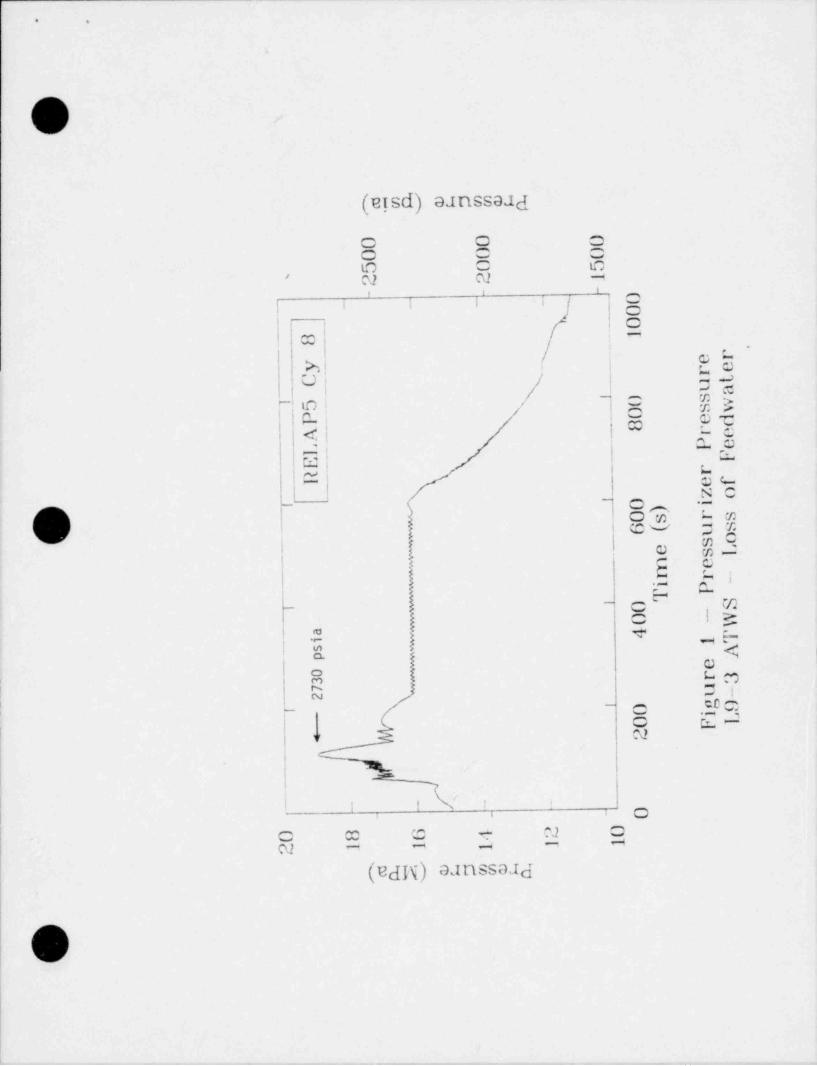
147.1 Maximum Pressure Planning .................................
7.2 Parameters Affecting the Value of the Maximum Pressure .... 15
7.2.1 Power to Volume Ratio ............................. 15|
%7.2.2 Moderator Temperature Coefficient ................. 16
!
7.2.3 Steam Generator Secondary Inventory ............... 17
7.2.4 Timing of Turbine Trip ............................ 18
7.2.5 Pressurizer Vapor Volume .......................... 19
7.2.6 Primary Relief Capacity ........................... 20
'
207.3 Auxiliary Feedwater .......................................
217.4 Recovery Procedure ........................................
7.4.1 High Pressure Injection Boric Acid Solution ....... 22i
7.4.2 Control of the Auxiliary Feedwater Flow ........... 22
7.4.3 Termination of the Test ........................... 23i
24REFERENCES...........................................................
25APPENDIX--PLANNING CALCULATION .......................................!1
PARAMETERS .................................................
FIGURES 1 THROUGH 18 ......................................., s
,
%d
iii, .
f
|
(l
- -- __

a_-. uu-a_A4,.a 4_.-- wem 4- h-h-'a a-- - M- --- 4 --s--LE ----a - A- .- -s- 6 -.--._ - - . - _ _ai m a a
FIGURES
1. LOFT L9-3 Test System Configuration . . 9
.
1
:t
l
!
|
|
|
|
l
I
I*
!!
e
iv |
_ _ _ _ . __..._ _. _ _-.--._ --- _-~_ --- ---- -- - -- -

. , - - _ - - - - . _ _ _ , : - _ _ _ _ _
- ,
3; . ,) d' ' , .
! ,
J., v -sj,
' ~
( wACRONYMS AND NOMENCLATURE
1 '
|- ' ..
, ,
' .xxe'American Society ofsMec5anical Engineers: s. *
N* ASME ,
j .r a, x ss
I ATWS * '- Anticipated Transient Without Scram s
| 's~
't
BST Blowdown Suppression Tanki! );'-,
w , y,
-
i CFR Code of Federal Regulations,
4
.
ECCS Emergency Core Cooling System,
! EFPH Effective-Full-Power-Hours,
| EOS Experiment Operating Specification s
..
Experiment PredictionEP
ESA Experiment Safety Analysis -
.
| HPIS High Pressure l'njecton System'
IDAR Instruqent aqd Data Acquisi. tion Requirements,
,
! keff -Effective Neutron Multiplication factor
) LOCA y loss-of-Coolant Accident (
! LCFTg . Loss-of-Fluid Test xs
i 3
MPa 106 Pascals .
|,,
, >~
I MTC Moderator Temperadsfe Coefficient '-
' . x-
| NRC Nuclear Regulatory Commission',
x s-
I
! PORV Power Operated Relief Valve.
! ,
PRD , Pressure Reduction and Decontamination'.s
phiay Pounds per Square Inch, Absolute .
t
PWR Pressurizee ifter Reactor
%. 'N
*
%
N
4
.
'
%/ ,
s
t-
s
\
s
I'
- - _ - , - - . - . ~ . _ . . . . - _ - _ . _ _ , _ _ _ _ ~ . . . . _ . - _ . _ . _ _ - . . _ _ . _ , ....--.-,__.--...-e . _ - . - - , _ , _ . - -. ,, , , - - - --_m .
. .. - . _ _ - . _-.
< >
LOFT EXPERIMENT DEFINITION DOCUMENT NUCLEAR TEST L9-3
OV 1. INTRODUCTION
Anticipated Transients Without Scram ( ATWS) for light water reuctorsis an unresolved safety issue of the U.S. Nuclear Regulatory Comission(NRC). The significance of ATWS in reactor safety is that some ATWS eventscan result in high system pressures which can potentially lead to fuel
4
damage and the release of a large amount of fission products.
Despite differences of opinion within the nuclear industry, theregulatory staff of the NRC has consistently held that "... the likelihoodof severe consequences arising from an ATWS event is acceptably small, butthat the future likelihood of severe ATWS consequences could become
unacceptably lar e and measures should be taken to diminish such;
consequences."(2 To address the ATWS issue, the NRC in September 1980
published a proposed ATWS ruleU) to amend the Code of Federal'
Regulations (10CFR50). After a year of public meetings and comments, the
b) NRC will soon issue a revised ATWS rule (November 1981). The Code of,
t
! Federal Regulations may then be amended and the regulation is expected tov
include measures both to reduce the likelihood of ATWS events a'nd tomitigate the consequences of an ATWS once it has occurred.( )The
planning of the L9-3 experiment is based on NRC's regulatory position,
Icontained in SECY-80-409 as well as those expected to be addressed in'
the forthcoming revision to the ATWS rule.
| In evaluating ATWS accidents the NRC lists ten initiating events for>
pressurized water reactors (PWRs), which are expected to occur one or more,
times during the life of a nuclear power unit. These events can be
classified into four categories, i.e., (a) reactivity related accidents(rod withdrawal, boron dilution, inactive primary loop startup, loadincrease, excessive cooldown), (b) degradation of reactor heat transfer
;
(loss of primary flow, loss of electrical load, loss of normal electricalpower), (c) degradation of reactor heat sink (loss of normal feedwater),
! O1
;
r
- - - , - . . . , . , , . - . - , . _ . - . _ _ - - _ . 4 - . . - . . --
- - - . - . - - _ _ - - - -

_ _ _ _ _ _ _ _ _ _ _ _ _ _ _ _ _ _ _
< ,
and (d) primary system depressurization caused by accidental opening of apressurizer relief valve. The L9-3 experiment is intended to simulate theimportant physical conditions following a loss of feedwater without scramtransient hypothesized for future commercial PWRs conforming to theacceptance criteria proposed by the NRC.I
Upon loss of feedwater to the steam generators in a PWR power plant,the heat transfer from the primary to the secondary system is degraded with
the decrease in steam generator secondary inventory. Normally the reactorwill trip (insert control rods to shutdown the reactor, or scram) on asignal of low feedwater flow or low steam generator level. In the absenceof a scram the steam generator secondary will soon boil dry and most of theheat produced by the reactor core will be dissipated in the primary fluid,raising its temperature. The expansion of the primary fluid associatedwith its temperature rise at first compresses the vapor space of thepressurizer, forcing the relief and safety volves to open. Subsequentlythe pressurizer will be filled with liquid water and the system pressurewill continue to rise to a maximum when the volumetric relief flow rateequals the volumetric expansion rate of the primary fluid at constant
It is this maximum pressure that constitutes one of the mainpressure.
safety concerns of ATWS events.
According to PWR vendors calculations,4 a loss of feedwater ATWS
yields one of the highest primary pressures among the initiating eventsmentioned earlier (the others being loss of load or rod withdrawal at zeropower). With the exception of Westinghouse plants, such an accident in
presently operating large commercial PWRs early in their life will resultin maximum primary stresses exceeding the " Level C Service Limit" as
defined in Article NCA-2000 of Section III of the ASME Boiler and PressureVessel Code. Such stresses may cause large deformations in areas ofstructural discontinuity (Level C Service Limit) or damages to componentsthat may breach the integrity of the primary coolant pressure boundary(much higher than Level C Service Limit), leading to a loss-of-coolantaccident (LOCA). The NRC's proposed regulation will limit the maximum
primary stress to less than the " Level C Service Limit" in all components
m
2
_ _ _ _ _ _ _ _ .

9 e
except in the steam generator tubes whose integrity may be evaluated based
[D on a conservative assessment of tests and likely condition of the tubesover their design life. The LOFT L9-3 experiment is designed to achieve apeak primary pressure that will result in stress levels slightly below the" Level C Service Limit" in commercial PWRs. The L9-3 peak pressure will,
therefore, be representative of the maximum expected pressure in commercialreactors that will be allowed under future rulemaking.
Another major concern of a loss of feedwater without scram accident isthe long-term shutdown capabilities of PWR systems after the initial peakpressure has passed. According to the NRC staff, after evaluating the PWRvendors submittals in response to an NRC request on ATWS analysis,
long-term shutdown has not been adequately addressed by the vendors.2One reason is that the transient computer codes ,6,7 used by the PWR5
vendors are no longer applicable when significant voids appear in the'
primary system after coolant loss from the power operated relief valvesi
(PORV)/ safety valves; another is that the vendors have not clearlydelineated the recovery procedures and the corresponding mitigating
O j systems. The L9-3 experiment will explore a way to depressurize theg
primary system by timely latching open the PORV and by using the auxiliaryfeedwater system for additional heat removal. In addition, highconcentration boron solution will be injected into the system to
l permanently shut down the reactor. This will be at least a first step inbringing the reactor to a stabl' cold shutdown condition after a loss offeedwater ATWS.
V
3
|
-. ..

1
i ,
2. EXPERIMENT OBJECTIVES
,
To address issues relating to system response and plant recovery'
procedures following a loss-of-feedwater ATWS in a comercial nuclear pcwerplant, the following programmatic objectives have been 6 tablished for theL9-3 experiment:
1. Provide experimental data for benchmarking PWR vendors' ATWS
computer codes as requred by the NRC proposed ATWS rule (USNRC
SECY-80-409).
2. Evaluate alternate methods of achieving long term shutdown(without the insertion of control rods) following an ATWS event,to address concerns defined in the proposed NRC staff rule
(Federal Register Vol. 46, No. 226).
To support the above programatic objectives, several specific testobjectives for the L9-3 experiment have been defined. In establishing
these test objectives, it is realized that results from the LOFT experimentmay not necessarily be directly applicable to the larger comercialplants. However, by application of the codes to LOFT results, it isexpected that an assessment of the capabilities of the codes to predictimportant system response characteristics during an ATWS event in acomercial pressurized water reactor can be obtained. Therefore, the testspecific objectives for L9-3 are:
1. To achieve a maximum primary system pressure that is several
measuring standard errors above the code safety valve opening
pressure setpoint but below 110% of the setpoint pressure,
i 2. To determine the transient reactor power by using availableneutron flux instrumentation and measured core thermal-hydraulic
parameters to assess the applicability of the point kineticsmodel used in predicting transient reactor power.
|: o
4
__ _ _ _ _ _

_ _
i ,
3. To determine the steam generator secondary dryout behavior andA its effect on the primary system response characteristics.
4. To determine the two-phase and subcooled flow characteristics of
the experimental pressurizer PORV and safety valve at high
| pressures (> 17 MPa (2500 psia)).
,
In support of the above objectives, the test should provide data on at'
least the following parameters with a time resolution of 1 second or lessin the first 250 seconds of the transient:
1. Pressurizer pressure, level, and temperature
:
2. Primary system average fluid temperature, core average fluid
j temperature, and cladding temperatures
3. Steam generator level and pressure
f
4. Transient reactor fission power derived from neutron flux| measurements
,
5. Pressurizer PORV and safety valve flow rates
6. An estimate of the primary system leakage rate in addition to,
| PORV and safety valve flow rates.
The recovery procedure consists of manually latching open the PORV todepressurize the primary system and manually initiating high pressure
;
| injection with high concentration boron solution. The auxiliary feedwaterI system will be used to regulate the cooldown rate of the primary system.
Specifically, the objective of the recovery procedure is to answer thequestion:
,
!
5
i
;
. _ . . - - - - . _ _ _ _ _ _ _ _ - , _ _ -
_ _ - _ __

. ,
With a present design of the high pressure injection system and theauxiliary feedwater system (the Trojan PWR), can the reactor be brought toa safe cold shutdown condition without inserting the control rods following
a loss of main feedwater transient?
:
'
.
I
{i
,
,
I
|
|
:1
6
i
. , _ , _ - _ _ _ _ _ . _ _ _ . , _ _ . . _ . _ _ _ , _ _ . . _ . _ _ . . . _ _ _ _ . . . _ _ _ _ . . . . . _ . . _ . _ _ _ _ _ _ _ _ _ _ _ _ _ _ . . _ _ . _ _ _ _ . _ . _ _ _ . _ _ . . _ _. ---_

. ,
3. SYSTEM CONFIGURATION
The system configuration for the L9-3 experiment is shown in
Figure 1. During most of the transient, especially during the phase whenthe experiment is to provide benchmark data for computer code assessment,the inactive broken loop fluid has negligible effects cn the system
For this reason and consistent with plant modificationresponse.constraints, the steam generator and primary coolant pump simulators in thebroken loop shall be isolated from the system; the broken loop hot legshall terminate at flange FL-19 and the broken loop cold leg shallterminate at isolation valve CV-P-138-2. Other explanations on the system
configuration are given below.
1. The reflood assist bypass valves CV-P-138-70 and CV-P-138-71
shall be closed during the test.
2. The pressurizer spray bypass valve V-4031-IVE shall be open
during the test and the pressurizer spray control valveCV-P-139-5-1 shall open and close in response to normal
pressurizer pressure control signals. Full flow through thespray control valve should be 0.57 kg/s (12 gpm, power scaled toa Westinghouse PWR).
3. The pressurizer cycling and backup heaters shall be operative.
4. The primary coolant pump injection system shall be isolated. ,
5. The primary coolant pumps PC-P-1 and PC-P-2 shall be operative.
; 6. The plant PORV isolation valve CV-P-139-18 shall be open and theplant PORV CV-P-139-5-4 shall be inactive and closci.
7. The experimental PORV and safety valves shall be simulated by aj
single valve, CV-P-139-87, with a double actuator such that the!
O>sv. -.
a
i
>. _ _

. ,
first position corresponds to the PORV and the second position
O corresponds to the PORV and the safety valves combined. (The
installation of a single valve in lieu of two or more valves inparallel, as in a commercial PWR, is due to the limitation ofplant space.) The PORV setpoints are: Open, 16.20 MPa,(2350 psia); close,16.00 MPa (2320 psia). The safety valvesetpoints are: Open, 17.24 MPa, (2500 psia); close, 16.46 MPa,(2388 psia).
8. The plant safety valves RV-200 and RV-201 lifting setpoint shall,
be 19.3 MPa (2800 psia) and be designed in such a way as to givethe maximum relief flow consistent with the plant configuration.A discussion of the setpoint is providad in Section 7.1.
9. The main steam isolation valve CV-P4-ll shall be open.
10. The steam control valve CV-P4-10 shall open and close according
to requirements given in Section 6.
)v 11. The main feedwater shall be shut off at the initiation of the
test, and the auxiliary feedwater system shall be operative inaccordance with requirements set in Section 6.
12. The primary coolant purification system shall be isolated duringthe test.
13. Only the high pressure injection system (HPIS) of the emergency
,
core cooling systera (ECCS) will be used in the test. The HPIS' should be able to inject 1000 kg (2200 lb) of 7000 parts per
million (ppm) boron (by weight) solution (temperature 300 K,80*F) at a rate of 0.38 kg/s (6 gpm) up to a primary systempressure of 17.2 MPa (2500 psia). The injection is into thedowncomer of the reactor vessel.
\V8
y , -7,. . - - - - - , -- -- - - _% __ _ _ _ +

,
_- ._ _ . . _ _ _ _ . _ _ _ ._ _ - . . _ . _ _ _ _ ____m. m._ .m. _ _ _ - m. . _ . - . _ _ . . _ . _ _ .. _ . ._
I1
i L
| -
F>
i
Ii
, .
!
|I -
,. F
I!
sv Hv136 IJF
to n 10
fha ~$ P PHU *
Surnp Suesp
'3m' CW.
g, t
F4RV p,
ft 'O200|6sn , 'to .nHv
201 5 teem teceg, = ...__.e..s, , .. - 6 .n
t 1G an - BST gy ,,'
5 en e Il 12 ,6* ;' M4.n recomenee ,g 3
pc w i p '
53*** | v 5000 CZpt 2 \ CV
k ,' \ F '3"i
pg p ,39 preessoa +2* ' 21 q g, * * ^ FL $Ausst ary teedeetet g
| 1, 7,| 1
v 3BO C2' ~ DST I1
l '" 16 en ECCed.e% vower"p g 39 S '" #*
he set 67 cv i - "" " O ' ' ' " 4 en *" ' "e
|I ga an %
kne p 13y LJ II ' go ,n'I
f o BST# '"
1 tre m Sg 3,,,
1I 1f1* jl j 7 ,9 p,w2182 en/ 9 433, ,y g b 76 70
10 b"'O' '''* HIO priniasy cooie ier
94 m pues.p qp.g
M '",
10en , '
10 see
PC P I [} Coed legPeenweise, 14 en
ia a ,,cv , r .i, c,0.no ip P 139 3 ,,j //heater
, , , _ _D 'l' |
-al
kso in ' * t is '" P'aa'r coo'*a' iu .aCv
Bar kup p g3g pump e
M *'8' 41
Qea~ 'o "
i cvva v sisi <7 p
PW -
im.um,gy . t ,,2 .s n.
. . . . ,, , , ,
.,,,e.n _ta Q'
, _. p p~ . . , , -
j _,,,a .n'
a
d ece44
!
) Figure 1. LOFT L9-3 test system configuration3
-
;
i
:1
I- _ ___ . _ _ _ . .._

.
- - - - - - - - ...
I
l 4. INITIAL CONDITIONS
Normal operating conditions in commercial PWRs vary from plant to
plant, so exact typicality considerations have little meaning. Instead,
the L9-3 Test initial conditions are designed to approximate commercial PWR
operating conditions and at the same time to be consistent with the safetyanalysis of the LOFT plant itself without compromising experimentobjectives.
The L9-3 experiment initial conditions are defined as:
i
1. Reactor power 49.5 0.5 MW
2. Average primary temperature 569.311 K (56512*F)
3. Core delta T (T ot - Tcold) 21.1 1 1 K (38 1 2*F)h
| 4. Pressurizer pressure 14.95 1 0.1 MPa (2169 1 15 psia)
5. Pressurizer level 1.168 1 0.05 m (46 + 2 inches)
| 6. Primary coolant pumps speed Consistent with reactor power andcore delta T
i
! 7. Control rod position 1.37 1 0.1 m (54.0 1 0.5 inches)
8. Main feedwater temperature Consistent with primary conditions1
9. Main feedwater flow Consistent with primary conditions
10. Main steam flow Consistent with primary conditionsI
( 11. Steam pressure Consistent with primary conditionst
12. Steam generator level 3.2 1 0.1 m (126 1 4 inches)above top of tube sheet
; 13. Boron concentration Enough to keep reactor critical4
|
|
t O,
10
:i
l
l, - . _ _ _ . . _ . _ _ _ _ _ _ . . _ _ _ . _ . _ _ _ __. _ _ _ . _ _ _ _

_
. ,
5. MEASUREMENT REQUIREMENTS
The following are important measurements to be obtained during the
L9-3 experiment:
1. Pressurizer pressure, level, and temperature,
2. Hot leg fluid temperature (Thot) and cold leg fluid temperature(Tcold), core average fluid temperature, cladding temperatures,
3. Steam generator level and pressure; steam flow rate,
4. Reactor neutron fluxes,
5. Pressurizer experimental PORV and safety valve flow rate and itsupstream density.
,
In addition to the above, the following should be ascertained beforethe test, monitored during the test or after the test:
s
1. Pressurizer spray and pressurizer spray bypass flows,
2. Primary coolant pumps speed and primary system loop flow rate,
3. Auxiliary feedwater flow rate,
4. ECC ir.jection flow rate,
5. Pretest monitoring of primary system leakage rate, and
6. Blowdown suppression tank (BST) inventory.
The important parameters of the test are shown in the planningcalculation (Appendix).
O11
- _ _ _ _ _ _ _ _ _ _ _ _ _ _ _ _ _ _ _ _ _ _ .

.
. .
6. SEQUENCE OF EVENTS
Prior to the initiation of the L9-3 Test, the LOFT reactor should be'
operated continuously near 50 MW such that the decay heat level at1000 seconds after a scram from 50 MW should be at least 800 kW. Thiscorresponds to an operating history of over 40 effective-full-power-hours(EFPH). After satisfying the requirement on decay heat build-up, thereactor should be brought to the initial conditions specified in Section 4as soon as practicable. During this period of pre-test operation, theplant leakage rate should be carefully monitored. Experimental datarecording should start at least 1 minute prior to experiment initiation.
To initiate the test, the main feedwater to the steam generator shallbe shut off at the fastest possible rate. The normal scram system (reactorprotection system) should be inhibited such that the control rods willremain at 1.37 m (54.0 inches) above the full-in position throughout the-test. The primary coolant pumps shall be kept running at constant speed asat the initiation of the test. The pressurizer sprays and heaters should
3respond to plant conditions as during normal operation. The experimental
D PORV and safety valve should operate as designed for the test.
With the steam control valve left open at its initial position, thesteam generator is expected to dry out about 100 seconds after terminationof feedwater flow. The steam control valve should be closed upon
t
indication of steam generator dryout (steam pressure below 4.14 MFa
i (600 psia)). The last action is designed to protect the steam generatortubes from overpressure but with little extra perturbation on the primary
transient.
The maximum primary pressure is expected to occur within about150 seconds after both the experimental PORV and safety valves are open and'
when they are discharging subcooled water from the pressurizer.
!)
12
I. - _ _ - . , - _ - _ __ . . __ .-. -_ - - - - - _ .

. .. -. . - . . ._ -
*,
NoSubsequently the valves will cycle near their respective setpoints.
manual actions should be taken until at least 10 minutes into the transient(measured from the initiating time),
TheThe recovery procedure starts at 10 minutes into the transient.i
operator actions are: (1) latching open the PORV, (2) initiating auxiliaryfeedwater, and (3) initiating high pressure injection. Subsequently the
+
PORV should be closed when the pressurizer pressure drops to 15.0 MPa>
(2175 psia). The auxiliary feedwater (temperature 294 K, 70*F) flow rateshould be used to control primary cooldown until the average primary
!
coolant temperature drops to 583 K (590*F) and then it should be used to
regulate the average primary temperature at around 588 K (600*F), or bej The steamshut off to maintain minimum cooldown of the primary system.
generator secondary pressure should be controlled above 4.14 MPa(600 psia). The high pressure injection should be kept on until testtermination (flow rate 0.38 kg/s, 6 gpm). The test will be complete when10 minutes has elapsed since the average primary fluid temperature first
drops to 583 K (590*F) after the initiation of the recovery crocedures..
The expected test transient history is shown in the Appendix at thev'1
f end of this document.i
!
1
!!
!
i
i
!
1
: O13.
i
ww _m r.m . . w-e---- ,..--.w >m.y-e yw -----+,.-e.-n%p- - --%-, --->y- -- e nrp - ., % w er = = *u.'

* .
7. DISCUSSION,
!v/ 7.1 Maximum Pressure Planning
According to NRC's proposed regulation, the maximum calculatedpressure for an early-in-life commercial PWR ouring an hypothesized ATWSaccident should be below a pressure that will cause a Service Level C Limitstress to occur in the primary system except in the steam generator tubes(see Introduction). This pressure corresponds approximately to 120% of thedesign pressure which is usually 17.24 MPa (2500 psia). In order to
provide benchmark data on the most severe pressure transient resulting froman ATWS for code assessment, it is therefore necessary to achieve a peak
pressure slightly below 20.69 MPa (3000 psia) during the experiment.
The LOFT plant at the present has a design pressure of 17.24 MPaIf the maximum(2500 psia), a typical design pressure for commercial PWRs.
pressure during the L9-3 experiment does indeed cause Level C stress in theprimary system (corresponding to a pressure above 18.96 MPa (2750 psia)),
/m\ extensive requalification of the plant may have to be performed after the)
test and damaged components, if any, have to be replaced. Costconsiderations, therefore, set an upper limit on the pressure to be
achieved during the test.
The lower limit on the maximum pressure to be achieved during the L9-3
experiment is constrained by the experimental objective of obtainingbenchmark data for code assessments. Measurement uncertainties, plant test
conditions, and model sensitivities probably will result in maximumpressure uncertainties of 1.4 MPa (200 psia). In order to evaluate the
capabilities of the codes to predict a peak pressure, the planned peakpressure should therefore be approximately 1.4 MPa (200 psia) above the
safety valve setpoint, or the design pressure.
/\ !w./
14
-

= ,
Based on the above discussion, the planning effort has been directed
] toward achieving a maximum pressure of 18.6 MPa (2700 psia), a pressurethat will not require extensive plant requalification and at the same time
will provide some challenge to model calculations.
Although at a pressure of 18.6 MPa (2700 psia) the LOFT plant is notexpected to be damaged, the plant must be protected against higherpressures during the test. The two plant safety valves (RV 200 and RV 201)will be installed for this purpose. These two valves are designed to givethe maximum relief capacity consistent with the current plant configurationsuch that when they open at any time during the transient, further pressurerise is limited to a few tenths of MPa (a few tens of psi). If these
valves would open, the experiment, of course, would be terminated. In
order to prevent an early abort of the test, the opening set-point of thesevalves is planned to be set at 19.3 MPa (2800 psia) pressurizer pressure.
7.2 Parameters Affecting the Value of the Maximum Pressure
The most important parameters affecting the maximum pressure attainedduring a loss of feedwater ATWS are (a) initial power to coolant volumeratio, (b) moderator temperature coefficient, (c) steam generator inventoryat the time when feedwater is lost, (d) the timing of turbine trip (closingof the steam control valve for LOFT), (e) initial pressurizer vapor volume,and (f) total relief capacity of the pressurizer. These are discussedindividually in the following subsections.
7.2.1 Power to Volume Ratio
The initial reactor power to coolant volume ratio affects the pressuretransient in two ways through the rise in the coolant temperature after theheat sink is degraded or lost. First, a rise in the coolant, or moderator,temperature will cause a decrease in reactivity and, hence, in reactorpower; the higher the rise in temperature, the more the decrease in reactorpower. A high power to volume ratio will cause a higher initial
f b
| 15
i_ _ _ _ _ .-.. _ _ _ _ _ . . _ - . - _ _ _ _ _ _ . . . _ . _ _ . _ . _ _ . _ . . _ _ . _ _ . _ -

* ,-__ ~ _ _ _ - . - - . _ - . . - . -~.
r
temperature rise rate, but a faster feedback so that the eventual-
7
temperature rise rate will be alleviated to some extent. (It should be
reiterated here that the peak pressure occurs when the primary coolant.
expansion rate at constant pressure, which is a function of the temperaturerise rate, balances the relief rate.) Secondly, for the same power, a
|small coolant volume will have a higher temperature rise, but since the
,
coolant expansion coefficient (volume increase per unit of temperature)increases with temperature, this will tend to increase the maximum pressure.
:
The coolant " volume" that is being discussed in this subsection is
more appropriately defined as the effective volume of the coolant that isi
actually heated up during the transient. Therefore the pressurizer,anddead-ended volumes in the system should be excluded in the consideration.
3The effective volume of LOFT is 5.4 m3 (190 ft ) and its initial poweris 50 MW. The Trojan plant, a Westinghouse PWR, has an effective volume of'
3303 M3 (10,700 ft ) and a power of about 3400 MW. The power to volume3
! ratios of LOFT and Trojan are respectively 9.3 MW/m3 (0.26 MW/ft ) and3
! 11.2 MW/m3 (0.32 MW/ft ). The lower ratio for 1.0FT will tend to give a
lower peak pressure during a loss of feedwater ATWS.
1; 7.2.2 Moderator Temperature Coefficient
What is usually referred to as the moderator temperature coefficient.
(MTC) is actually a combined coefficient of several factors. The moderatorin a PWR is a dilute aqueous boric acid solution. The boron in thesolution is used to reduce the excess reactivity in the reactor core and
i
the water molecules to moderate fission neutrons to thermal energies forfurther fission. As the temperature of the moderator rises, it expands and
1
the moderating capability is reduced. This will (a) cause more leakage of
neutrons from the reactor core and (b) less fission due to the reduction infission cross-section. On the other hand the reduction in boron densitydue to the expansion will decrease the neutron absorption rate, preserving
| more neutrons for further fission. These combined effects in general make
||
O16
i
_, , , , _ . _ , , . . _ _ . _ _ _ . _ . . _ , _ . . _ _ . _ _ _ , . . _ . . _ . . _ __ - _ . _ . _ _ _ _ _ _ _ . _ - _ , _ _ _ _ _ _ . _ __

*.
the MTC negative ir, PWRs, except possibly at the very beginning of theiroperating life. The nTC decreases (becomes more negative) with operatingO life of a PWR as the boron concentration is reduced.
The MTC is usually expressed as a change in keff per degree changein the moderator temperature. From a reactor power transient point of view
divided by theit is more appropriately expressed in dollars (keffdelayed neutron fraction) per degree temperature. For generic WestinghousePWRs early in their operating life, the MTC is about -50.02/K(-$0.012/*F). For LOFT at the time of the L9-3 Test, it is estimated to be-50.069/K(-$0.039/*F). The more negative LOFT MTC will give a fasterpower decrease for the same rise in temperature. Consequently if all otherparameters were scaled to Westinghouse PWRs, the peak pressure during theL9-3 Test would be less than those experienced by Westinghouse PWRs early
in their operating life.
7.2.3 Steam Generator Secondary Inventory
The initial steam generator secondary inventory determines the powerlevel of the reactor when the steam generator is boiled dry completely.
Following steam generator dryout, practically all the heat generated in the;
reactor core will be dissipated in the primary coolant, raising itstemperature. The larger the initial steam generator inventory, the longer
I will be the dryout time and consequently the lower will be the power levelat the time of dryout oue to moderator temperature-reactivity effects.Therefore the maximum pressure during the transient will be lower for a
reactor system having a larger initial steam generator inventory. Forreactors of different powers, the ratio of the steam generator inventory tothe power is the relevant parameter.
For 4-loop Westinghouse PWRs, the steam generator inventory isequivalent to the steam produced in about 100 full-power-seconds; for LOFT,it is 75 full-power-seconds. Assuming other conditions being typical, theLOFT reactor will have a higher maximum pressure during a loss of feedwaterATWS than 4-loop Westinghouse PWRs.
O17

_ _
* s,
i
7.2.4 Timing of Turbine Trip
s
in a Westinghouse PWR, a turbine trip (closure of all turbine steamInadmission valves) will be initiated on receiving a reactor trip signal.
an ATWS accident, the failure to trip the reactor is usually attributed tothe failure to cut off electrical power to the reactor control rods or tomechanical blockage in the reactor core such that the control rods cannot
,
be inserted. The contribution to the probability of failure to scram fromsignal failures is negligibly small because of the reliability ofelectronic systems and the degree of redundancy built into the systems.Upon loss of feedwater to the steam generators, a reactor trip signal maybe generated from (a) steam flow-feedwater flow mismatch coincident withlow steam generator water level, (b) low-low steam generator water level,
,
(c) pressurizer high pressure, or (d) pressurizer high water level. In an
ATWS, a turbine trip is, therefore, likely to occur before the steam
J generators boil dry.
A turbine trip before steam generator dryout will have the effect of:
| Q temporarily raising the primary temperature, reducing the reactor powerbecause of the moderator temperature rise. The steam generated following
turbine trip will be dumped to the atmosphere through relief valves in acommercial PWR. Due to the early reduction in the reactor power, the
integrated energy dissipation in the primary coolant will be less than itwould be otherwise without a turbine trip before steam generator dryout.
| Therefore the earlier the turbine trip, the less will be the maximum
pressure achieved during an ATWS.
In the L9-3 Test, the steam control valve will be closed when thesteam generator secondary dries out (pressure drops below 4.14 MPa(600 psia)). This is not a typical action in a commercial PWR, but is
,
designed to achieve a primary pressure higher than the pressurizer safety;
valve setpoint and to protect the integrity of the steam generator tubes.'
1
18
_ . - . _ __- ._- _ _ - _ - _ . . _ _ . - , _ . -
* *
Without such a late steam control valve closure, the primary pressure will( peak only slightly above the safety valve setpoint due to the large(
negative LOFT MTC.
7.2.5 Pressurizer Vapor Volume
During a loss of feedwater ATWS, the maximum pressure is expected tooccur after the pressurizer is totally filled with liquid water from theexpansion of the primary coolant. The time required to achieve thisdepends on the ratio of the initial pressurizer vapor volume to theeffective primary coolant volume; the higher the ratio, the longer the timeinterval, assuming the same power transient. The reactor power is expectedto be a monotonically decreasing function of time, so the peak pressurewill be lower when it occurs later in the transient, since lower reactorpower means lower coolant expansion rate. The relief capacity is assumedto increase with pressure.
Pressurizer level settings vary from plant to plant in commercialPWRs. For example, the Zion plant has the same pressurizer volume as the
3 3Trojan plant (51 r.i or 1800 f t ), but the Zion operating pressurizervapor volume is about 18 m3 (650 ft )l0 while that of Trojan is3
334 m3 (1200 f t ), according to the Trojan Final Safety AnalysisReport.II The LOFT L9-3 Test initial pressurizer vapor volume is
3approximately 0.28 m3 (10 ft ). The ratios of pressurizer vapor volume
to effective primary coolant volume are 5.3% for LOFT, 5.6% for Trojan, and10.7% for Zion. The reason for setting a low ratio for LOFT is againintended to increase the maximum pressure during the transient to
counteract the overwhelming effect of a too negative MTC. The setting isalso consistent with safety requirements for the operation of LOFT.
I
!
!
,
!O.
19
|
l

. .
7.2.6 Primary Relief CapacityGU The primary relief capacity is probably the most important parameter
which can be adjusted in LOFT to give the desired maximum pressure during aloss of feedwater ATWS. The total relief capacity in most commercial PWRs'
consists of relief flow from the PORVs and the code safety valves installedon the press _urizer. The higher the relief capacity, the lower will be themaximum pressure during an ATWS, assuming the maximum pressure exceeds the2
opening setpoints of the valves. If the volumetric relief flow rate islower than the primary coolant expansion rate at constant pressure when thevalves first open, the pressure will keep increasing until the relief flowrate equals the expansion rate.
The L9-3 Test PORV is sized to relieve 0.66 kg/s (5250 lb/hr) ofsaturated steam at 16.2 MPa (2350 psia) upstream pressure, a valueconsistent with the minimum PORV capacity of Westinghouse PWRs on a power
scaled basis (1.33 x 10⁻² kg/s-MW, or 105 lb/hr-MW). In the initial
pressure rise during the transient, the PORV will be open at 16.2 MPa(2350 psia), but the pressure will keep rising until the safety valve
;opening setpoint (17.2 MPa, or 2500 psia) is reached. Further rise in'
pressure will depend on the relief capacity designed for the safety valve.
In order to achieve a maximum pressure of 18.6 MPa (2700 psia, see
Section 7.1), planning calculations show that the safety valve reliefcapacity should be set at 1.26 kg/s (10,000 lb/hr) saturated steam at17.2 MPa (2500 psia) upstream pressure. Incidentally, this relief capacity
approximately corresponds to the relief capacity of two out of three safetyi valves in Westinghouse PWRs on a power scaled basis.
7.3 Auxiliary Feedwater
In a Westinghouse PWR, when the steam generator feedwater pumps arei
tripped, the auxiliary feedwater pumps will automatically start and deliverlow temperature feedwater to the steam generators. The auxiliary feedwater
G20
:
. . .

. .
system will also automatically operate when a low-low steam generator water
level is detected. In general, part of the auxiliary feedwater isdelivered by a steam turbine driven pump, the rest by an electricallydriven pump (s). Trojan plant has two electrically driven auxiliaryfeedwater pumps, each capable of delivering 60 kg/s (960 gpm) 294 K (70*F)water. The LOFT auxiliary feedwater system is capable of delivering1.0 kg/s (16 gpm) 294 K (70 F) water. An attempt should be made to use thefull capacity to simulate approximately that of one electrically drivenauxiliary feedwater pump at the Trojan plant on a power scaled basis.Actual plant temperature and pressure condition at the time of recovery mayrequire lesser feedwater flow rate to sucessfully regain plant control.
Due to the large negative MTC in LOFT, the startup of the auxiliaryf eedwater will be delayed until the pressure peak has passed. In fact, the
auxiliary feedwater will be delayed until the recovery portion of the testdue to temperature typicality considerations. (See Section 7.4.2)
7.4 Recovery Procedure
The concept of a recovery from an ATWS is to bring the reactor to a'
stable cold shutdown condition indefinitely without ever inserting the!
control rods. To do this, high concentration boric acid solution has to beinjected into the reactor core. In the Trojan plant, upon initiation of
,
3high pressure injection, 3.4 m3 (120 ft ) of 21,000 ppm by weight baron,
solution will be injected into the primary system against a system pressurebelow about 18 MPa (2600 psia) followed by an almost unlimited amount of2000 ppm by weight boron solution. During the early operating life of a'
commercial PWR, the capacity of the 21,000 ppm boron may not be capable of'
assuring reactor subcriticality at cold shutdown temperatures less than370 K (=200 F) wihtout control rod insertion. So a large amount of2000 ppm boron injection may be required over a long period of time. If
during this time the primary temperature decreases so fast that thepositive reactivity addition from the moderator temperature feedback
|O21
- . - . ._. _- . -. -. ..-. . - . - .- . - _ - . . - - _ -

. - . - .- - .
. <.
4
exceeds the negative reactivity addition from the boron solution, thereactor will become critical again and the subsequent recovery will be>
considerably more complicated. The L9-4 Test recovery is designed to bothinject boron solution and control the primary system cooldown rate.j
7.4.1 High Pressure Injection Boric Acid Solution
i
Owing to the limitation of the LOFT facility and the short periodallowed for test planning and preparation, the LOFT HPIS cannot be modified
to simulate that or commercial PWRs in the L9-3 Test. Instead, 7000 ppm
baron solution will be used in the test. This will assure that the reactor;
will be kept sufficiently subcritical during the recovery such thati
recriticality will not occur.
Another typicality of the L9-3 Test HPIS is that the injection is intoi the reactor vessel downcomer instead of the cold leg. The reason is that
|the cold leg injection train of the HPIS is required for pre-test reactorcontrol with low concentration boron solution. This difference in the
|injection location in the L9-3 Test and is commercial PWR is not expected
to be significant.,
7.4.2 Control of the Auxiliary Feedwater Flow!
The initiation of auxiliary feedwater at 10 minutes into the test isnot considered as part of operator actions. In a commercial PWR, the
auxiliary feedwater will come on quite early after the loss of mainfeedwater to the steam generators as mentioned earlier (Section 7.3). If a
|loss of feedwater ATWS were to occur at a commercial PWR early in its'
j operating life, even with early auxiliary feedwater initiation, the primary,' coolant temperature would approach its saturation temperature in a short
interval due to the slow decrease in reactor power. On the other hand, thelarge negative LOFT MTC will drive down the reactor power quite fast,;.
giving a much slower temperature rise. The delay of the initiation of the|
| .
I22
. _ _ _ _ _ _ _ _ _ _ _ _ _ _ _ _ . _
. . _ _. - - - - -. . ._ -
- .
auxiliary feedwater in the L9-3 Test is designed to achieve temperature
() typicality to a commercial PWR in its early operating life, just as the
! relief valve is sized to achieve pressure typicality (Section 7.2.6).
Later in the recovery, the auxiliary feedwater will be turned on andoff to control the primary coolant temperature around 590 K (=600*F) orto achieve a minimum cooldown rate by turning it off until testterminatica. These actions are properly considered as operator actions.
7.4.3 Termination of the Test
The termination criterion as discussed in Section 6 will assure theacquisition of the necessary information for assessing the interaction
f characteristics of the HPIS fluid with the primary coolant. It will also
give valuable information on the controllability of the reactor systemtoward a cold shutdown without inserting the control rods.
1
-
1
i
!!
i
S,
1
23|
|
t

- _.
. .
REFERENCES
/ \
b1. " Proposed Rulemaking to Amend 10 CFR Part 50 Concerning Anticipated
Transients Without Scram (ATWS) Events," USNRC SECY-80-409,September 4, 1980.
2. " Anticipated Transients Without Scram for Light Water Reactors," NUREG0460, Vol. 4, March 1980.
3. "Liticipated Transients Without Scram for Light Water Reactors,"NsREG-0460, Vol. 2, Appendix IV, April 1978.
4 " Anticipated Transients Without Scram for Light Water Reactors,"NUREG-0460, Vol. 2, Appendices XIV, XV, and XVII, April 1978.
5. "CADDS - Computer Applications to Direct Digital Simulation ofTransients in PWRs With or Without Scram," Babcock & Wilcox Co. ReportBAW-10098, Rev.1, February 1978.
6. CENPD-107P, "CESEC - Digital Simulation of a Combustion EngineeringNuclear Supply System," April 1974 and Suppl. 1P, April 1974, Suppl. 1Amendent 1P, November 1975, Suppl. 3, August 1975, Suppl. 4-P,December 1975, Suppl 5-P, June 1976 on "ATWS Model Modifications toCESEC."
7. "LOFTRAN Code Description," Westinghouse Electric Corporation Reportp) WCAP-7878, Rev. 1, January 1977.(,
%J8. " Proposed Rulemaking to Amend 10 CFR Part 50 Concerning Anticipated
Transients Without Scram (ATWS) Events," USNRC SECY-80-409,Enclosure E, September 4, 1980.
9. " Anticipated Transients Without Scram for Light Water Reactors,"NUREG-0460, Vol. 4, Appendix B, March 1980.
10. J. E. Koske, Private Communication.
11. " Trojan Nuclear Plant Final Safety Analysis Report," Portland GeneralElectric Company, USAEC Docket No. 50-344, February, 1973.
i
r
U24
l-. . - . _ - . . - . - . - _ _ _ . _ _ . .-

- . _ . - _ _ _ ..
. .
4
APPENDIX'
i
PLANNING CALCULATION
The figures shown in this appendix are ootained from a RELAP5
|calculation using a LOFT model derived from the one used in theLOFT L9-1 Test Experiment Prediction. The calculation should not beconsidered as an experiment prediction since the model has not incorporated
the improvements made since the L9-1 Test, such as ambient heat losses and7
| an upgraded steam generator model. The calculation also does not followprecisely the parameters defined in this document. The figures should beI
used as a visual aid to the understanding of the test and as a reference to
design measuring instrument ranges.,
i
i
l
i
4
!
.
4
i
!
I'
. .
i
,' 25
_. _ ... - .- -- - - - _ _ . . _ - . . _ , . - - - . . _ . - . . - - . - , - _ - - . ... - -- - . .- - - ~ . - . . _ . _ -

l|
. .
,
OFT , TE. A eA. CF ATER4
INITIA_ CONDITIONS
Aerage Pr imary Tenperature. . . . . . . . . . . . . . . . 565 FPressurizer Pressure....................... 2168 psia
~
Core Delta T............................... 38 FPressurtzer Level.......................... 46 inReactor Power.............................. 50.0 tWOperating History.......................... 40 efph
Axiliary Feedwater at 600 seconds, 16 spm, 70 F
OPEPPTOR ACTICNS AT 600 SECONDS
Latch open PORY to depressurize to 2175 psia and then close it
Initiate safety injection, 6 spm, 70 F, 3000 ppm baron
E)PERIPENTR_ RELIET VAX CHWACTERISTICS
PORY: Open, 2350 psla; Close, 2320 psia;Saturated Steam Flow at 2350 psia: 5250 lb/hr
Safety: Open, 2500 psta; Close, 2470 psia;Saturated Steam Flow at 2500 psia: 10,000 lb/hr
Steam Generator Secondary Pressure subsequently controlledbetween 400 and 450 psia
-
--- . _ - _ _ _ _ . - - _ _ __
,| | i
.
.
_
g _.
1
_
gsaU euo$$rL?
-
0 0 00 0 05 0 52 2 1,
- - -
- - - 000
_
_
-
18r'ey r e
C u at_
s3 5'
0 sw0_ P_ 8 ed
r e .
. A -
Pe .
-
- L PE r _
.
.
- R ef ,
. zo' 0.
,
0)s rsie- -
6( us-
- ose sL
-. m r-.e .
~~
i P-
' Ti 0 S
0 - W ..
_
a 4 1T_
,
_
- i -- A _-
s -
p e _
0 r3-
3-
u--
7-- 2
-i k ' 0 g9-
.i L0 F
-
: 2
v-
- -_
-
~ 0-,
_
0 8 6 4 2 0'
2 1 1 1 1 1
2B6 S ~Dy"0: 4_
'
@
-
i! ,i,!! !i|.!,! 4 i i )I|l:I

-
'I
* e
a
R
(ut){ GAOLt'
o \'O C CQ C T N
i ii, gi
, i gO"
CO.-
a ~>-
65
c$- O >,
O C4O E<
a u2rg o-.N (-
N-
M-
~
C m,4 p|
.
0 m,o 8o- gt -
e u-b CL.
.i.
p.ms.
_- o- w
C NU,
e :_.,
'
O ,Ws,
L%
O,- e,e sm I
~
O -.
x N
t .
| ',
1.| ! ~i)
!. O, n * *
1 cd ~ ~ C
h (tu) IOAOl'
1''
i.
;
1
4
5'
t.._.__-,. . - _ _ _ _ . . _ . _ , _ . _ _ _ _ _ _ _ _ . . _ . _ _ _ __ __ _.

;
'. .
,, - _ .
I :,
i
@ iF |
r
:.'
i'
'
(do) alnauaadwal Il!
Ii o o o
+ N o (: o o o'! o
, , i ,
| | I o L ;'
o C I1
i "e i.oo -
; % .- ,
C.
h! n o .
,
i,
O po; e c-
- c o -
t e a 02 .
;
I s o & - :C iw
J % O i
'A Dk; g .N ,'1
-%L o
f- o ;moe z mev m zeo ,o L ._:
<
C 1 i~.
- i ;
'r* G |.' r|
- - o o rn! O Sb' + cr
AQ| m :
Ico-
- o o .
JO oN
3.ot
[ !i. oi ,
.
o o o o o .
N * o Q COio o o O O
(>[) aan]e.Iedwal ;
@.
-- _ - . . . - --_ - - - - . - - _ _ _ _ ~ - - . . - . - - - . - . - - . - . .-

1. .
1
!@,
i
i4
I .
i:
| (do) aanaeaadulal,
'
o a o =i iw a e cii D D CD Ci
i i i i f a e' ' ''
o ~s
l'a D
j- _am| c. .
,
,
f fJ
'
i
j.yf C'
; gyj- ci o-
i L /, o a-*< ( EE .
-
a :A LN! %; e.
% NL>eM R
!-
!'Om Loa m
; e- zA :W v -
j o e _: ;
i- a$ % t.
.L1
I.-
- h!- o t rA |'
| 0 > .
e EC |i ;%'
e i
T |'
ot - 1 o a ,
'
o uA |
N g |'
.e-N i
! | | |
. i . . O !,
o o o o o o+ M N' * C QC C O C C C
(>I) aangeaadwal,
@ .
- - _ . _ _ _ _ _ _ _ _ _ _ . -. - -- _ _ _ _. .- _ . _ . - - -

-.. . _ . _ _ - . - _ _ . _ . _ . _ - - - . - - - - - . - . . .. _ .. _
l -
- ~
:!
:..
Ii'
I;
I>.
!,
i1,
i |
| (do) aanquaadulal |
1
i o o o o iCC (C <* N '
fo o o o o j, , , ,
i i i i o L .
o 3 !, o a |
co - c rLes. m
O n o-
O po:e 2 ''
.
~O^ o c"' > |*
rP :: |cL o1 -
< o xL 5 [
'
r.c eE ,
:; e .s" t,,,, !
l - - o |' o--
, m!oz z z
'I cc v m* !z -
I C|
C LJ i.
\ h CL.
I |
2,
i - - 8= 5?n..-
~
i agi a Q.
.
!
! Dk ('
ti'
I m, !c
C- - o Q !d iO e 'N L
,
i D |.u i.
; .
I .! .! !. O ;.;
I o o o c o o .
o cn !I e a cu -
. o o o o o O .'
ts
(>I) aanleaadtual |!
@ \;
. Ii
i,
i<
v -m- w - -w e w , . . . - .-mm- .- --w~-w>~-e.-~~ --- - - , - . - - - - - - - - - - - - - - - - - - - - -

_ _ _ _ -
- - _ _ _ . _ . _ _ . _ . _ _ . _ _ . _ . _ . . _ . . _ . _ _ . _ _ ,
i . .
l i
!@ :i
)
(do) aangeaadwal.
o o oc o O ,
CD D .C -,
o, , ,
o L! | | 6 o o !! C a i
e| :: - c
L - i1
oL li h n e4 O rs
ds ;- e- o o i* .::
|c., o -
tD4, a ;c g1tM ,
% E '
%j- O- .--
C--
@; aw . m
c0 v z; aoo ,_:c
FQD>
I'
i,- d
L
:- - o& o en
<> bo
; + r_,- ';<
m4 C 1
o- - o ao ud; N y,
enC
i -
1
!l I l
i i o ,
i
o o o o o :
+ N o 00 CO L
a o a c c|
i
,-
i. (>I) aanicaadwal!
l
, ,
! [,
a
m m - w- w wm r - ._-.yv.w-- -- --wee.www-+.-.==ww. , . _ - - - - - - - - - -- - - .+

_ _ - - _ - . - _ - . - . . . - - . - . _ . . - - - - - . - _ - . - . _ - - - -.
.
|
'
|
k |2
!.
| (do) aangeaadulal ;'
1
! o o o !
i c o c| D o C |
1 1 1
'i i i o
o i
o * |o - - :
)1 p - ,
a u >
y.
| cc 0 ,
: o as-
oC!- o a> '- C
.
a o c4i s o CCvw ;
4 O C) 'i
: if bN! c;i ou
% O '
@- - o omoe omev z
o :O|* a
! $ F-i <.- *- a& v2
| C 3+ u:
! I k6 .
e t'
cI- - o :o
o 3JN . D.
o
w
! I i. , , o
o o o o oy N o CC CO
c D D D C
(x) aanaeaadwal
>
-,e---,. . . , -. .--. . - - - -. . - - - - - - - - . - - - - - - - - - - -

. .._ _ _ _ -_ _
..
O;
!!
(do) aanaeaadtuoio o c c I
D 4 N OO C C C I
;, , , ,
i l I i C i,.oO O" L |O
DL ~m 'oO.6 Ca
L dO~
- C O% >'% O
@3U< -
v ;a e 1 !M 9.'% c
yC |' %
- ,
% s ,
OD T t
cv O rn|; O-
: C Lar O
\
.b N|f
- e 3m~
\- C
a y: * I EI e<| o ni L Ii ~
!~ C 3C'C cu ~
N ~~
%,
i l i i< i i i i o4
! O O O O O Oj M N * O C CC
D D D D C Di
'
| ()[) OJn}UJadLUO1
|@|
!
4
>
#. - - - - - , , .n-------..--_ .-. _ _ . _ . . . . . . . . - . - . . . - _ . - - - . ~ - - . ~ -.

,
, .
@r
||
(do) aanleJadulal ,
o o o oo + cu o
Io o o oi
t I t t - o |i i i < o
o a .
- a !o?% '
> C '
O- d
u tc ce ,- c
- oa o af :
o cs<i ,
a 8o i
'A wk u
'
c: D IoI
- o 5 im 'oz U v:ov 7) itoo *J \
E e |i
: t I ;-i |
i - - o& p ro~
,
: O ic! *
I E<'
;'
: c) ;
O ,.
e;I .
t "Q r- - o Docu .E8 -
,
, ,
| % ;1l
,
!i i t i o [j s e e a
( o o o o o o !
o G QO N ~
o o o (O O O.
(>I) aangeaadwal
!
.
.---.-,-,_--__m_ m.,--.._- - - ._w- , - . .--_.--__%-,-- -,w,,. -- %mse- ww. wc-m-,-..w---.,--

__.__.___ . _ _ _ _ _ _ _ _ . - . _ _ _ _ _ _ _ _ _ _ _ - _ _ _ _ _ _ _ _ _ _ _ _ _ .
..
,t
,
I
!
i @j
!'t
I (do) aln;uaadulal!
.
| c o o o !e + cu o ;
.
j C o C o, , , , ,
;
i, i i i I oo ,
o O l
| cat- a
c, .
h a5a ,
'
i o a .
si- o o' - c
! a o ~4e pe
, -e,_a eaN NA
i Zi
t "o! __ o m
m -
oe azco w w'
'a a, le!
6 a,ae.
>c. ,-
- p' D ip
t o 3+ 1 ._.ok t
M .
e 'oe66_ _ g D ao
al .?s
|
I I I I
i i . i o-
o o o o o oa n2 - o a coe e o e o o
(>[) aanleaadt.ual
O
__ - - - _ _ - _ -__ _ - _

__ _ _ _ _ _ _ _ _ _ _ _ . _ _ _ _ _ _ _ _ _ _ _ _ _ _ _ _ _ . . _ _ _ _ . _ _ _ . . . _
._,
[
! @ 9 9 ~
~
> -|,
1 -
!
t
|J1-
1 I I ~I
RELAP5 Cy 8I
i
! O ---- 0
ii
i n- .E[ -1 -
-50 v-
-
e ? I-
> -- !
e -2 -- oa J
- -100 |-
! -3 - (- _ !~
i|
-
i i i i- -150
_40 200 400 600 800 1000
Time (s)
Figure 11 - Steam Generat.or LevelL9-3 ATWS -- Loss of' Feedwat.cr
I'
!
.. . - -. . - ._- _ _ - -. . . __ _ _ . -- _ _ ._ _ _ _ _ _ _
>-

.. . --- uw------~.- -- - _ -.----- ---.. -- . . - - - - - . - - -- - .- ~ ~ - -.-- - - - - - - . - . - . . - . ~ . . .
j . .
.
i
.,
'
; (u!sd) aanssaadi o o o o o oi o o o o o o
CC 6 C C T C*
t t i f f
i l ao eo %-
.
cc ,-
t mu -A m e,
O C s
1 >c~ c
I P O--
0'a o ji
a %? is~ c-a a2cc n-,
%! c 'CC| _
I_ OT C- a
' e iev az io r
$ E" |.
. aiaE s_
- O wo Cr2 >
.'-*I E<i
N>
! we1
- - o EC 1
o g- t
N '
en..-, w,
I I I. > > > > i o ;
O O 4 O N
(udW) aansseldi
!
>
:i
i4
,-..,_ _ .. - - . - . _ -. - _ - . _ . . . _ _ _ , _ - . _ - - _ _ - . _ _ _ _ _ _ _ . - . - . _ . - -- - - . - - .

_ - - . . _ - - . _ _ . . - . - . . . _ _ _ _ - - - _ _ _ - _ _ _ - - . .
. .,
l
!
Ii
(JM/QI 000T) aleg Atold
o o oo o o oN + - 0 O yi , , , ,
i i o eo'-
i : S %i w
_ _ ; r -
.
h c-O m3
. o e- _- _ O o d
w .>cCL oD b4 .
a 5oze o* Cu
-_ oOo? C mo mev
. OO! o a
E E,.- i
$wF- o
a wbv ._,
! I<co a* I
Q- O oc u-,
> N ?-a me==mammanum 9
_
- wc\ I i
i i i 4 oo o o oco cu -
(s/3>I) aleg Atold
\
_ - _ . .- . - . . - _ _ .- . -.. _ - __ - _ ___ _________ - _

, _ _ _ _ _ . . . ._ ._ ___ _ _ . . . _ _ _ _ _ _ . . - . . . . . _ . . _ _ . . . _ . . _ _ _ . _ _ - _ _ _ .
1 ,
t-; . .
I;
I *
.
!, S !.
t.
i.
1
!|
(AW) Jenod ,.'
e
i O O O O O OOi e o + O Cu -
', , . i r
. I i i i i OO
! O ;'
i cc -% -^ ,
i| k s$h 0O
! o= ';
- o ~ C a >' '
; 4 OM L c
o' a a .cCC 4
: % 0,cc -C) O
j-
~~ Cn c:; enO eni co v v;n
3O-!
!O '
b Peir .
i,,
- -
- O b4 fF
.
! w44
i L O| pl ,
- O uGO ~A,
,' CV N t
;
!
I i 1l. O. . ..
O O O O O O OO O t O CV "
'
i (AM) aemod1
.
. ,
i
!
i
1n
'et---p-=&w v~ g-w,.-. vs _ .-r.- - . - - - - - - - - - - - ' - - * - ' - - - - - - - - - - - - -

I
;. .
,
i
|~
,
|
!
!
(AilV) J0 Modi
O O O o o OO O 4 O N - o
I f ? t !
I I O i'O
OCD - t
G -
'
h CJ %> 0Q # a
S5- 0 - Oa O -
4 O C3A O&Er2 g
..D C.-.(.
E: O- ._ O m.
O :n u cn| C" O %''
9f e 4
O~MOJ l.
b %gi r - gO | 3 ;
- + :, t,
! 0%~
C-
I % IO =q r
O es "N ;~ ;
4
!, !,, , O< ,
O O o oC v N
(AtN) Jamod ,.
t
@;
.
' *
- - --- _
__ - .- - - - - - - . - . - - -

. _ - - - - . - _ __ - _ - _ _ _ . . _ _ _ - . . - - _ _ .__ -...- _ - _ _- - - .-..-.-- - _ _
|:
1
il
|
3.53.5 , , , ,
RELAP5 Cy 8- - 3.03- -
nm
- - 2.5 k5 2.5 -- %I % v
v
-- 2.0 8| @ 2--
ki k oI
o-- 1.5 A
4 1.5 --||| .. . 1.0|
1_ _|
|
f' ' ' ' O.50.5 -
0 200 400 600 800 1000Time (s)
Figure 1G - Reactor Decay PowerL9-3 ATWS - Loss of' Peedwater
111

___
OFlow Rate (kg/s)
o - iu a a ci
o , , i
I i I I
._. .--
m..ao to ;
~ec ocq o _ -
| oa- yn
->" i+#$$b*-3 i A
o 149 -$, 7,m ,o ===
: 2+n 1m0 -.I z mr-
m d ==c,rC o 45-o- + -n:-
$ d- { $ M-a o -om I s
M )'
gm@ mo ,_. r2 p' co >74 o T< o ui _
R_
Ic 9.~. O-O3 )N<
| co-oOo ! ! ,I
', ,
o W l'O QC o o
Flow Rate (1000 lb/hr)
O.
* O

,___ . _ _ . ___ _ _ _ _ _ _ _ . _ _ _ . - _ _ _ _ _ _ _ . _ _ _ .
,1. .
1 .
14
I
@' '
I
!i.
I
(g1J/4[) Xysuae ,
. ,,- o o o a o !+ a N -
[ t ' i
1 i i i o!
oo N'
.2~i co1, m.-I h d5! O e>
O=| - c
- o 3 !
a o,
ay* e a .1 < No~
,
5 '~ wc ouj mo -
!-
- o La*
mow 9m i4
-ev -z4o :
o A {
E,- ,
oij c a' ',
|- - o- a m
O oy.
* E-I<
cc -
{ edI
- - o eoo GA
t
N D.oe.
w,
(_ i i i i ;
i i i i o ,
o o o o o '
o o o oCC (D + N
w/8 ) AMsuag |(g M
@ !;!
i
- - . . . - ~ . . - ~ . , , , , , , . . - . . - . - - - - - . - - - - - -