lockout / tagout energy control - · pdf filelockout / tagout energy control ... control of...
TRANSCRIPT
1
Lockout / Tagout Energy Control
Table of Contents
1.0 Purpose / Policy ..................................................................................................................... 2 2.0 Responsibilities:..................................................................................................................... 2 3.0 Definitions .............................................................................................................................. 3 4.0 Program Elements................................................................................................................. 4 5.0 Training ................................................................................................................................. 4 6.0 Lockout / Tagout Survey...................................................................................................... 5 7.0 Hardware ............................................................................................................................... 6 8.0 Routine Maintenance & Minor Adjustments ..................................................................... 6 9.0 Lockout/Tagout Procedures, Sequence and Responsibilities............................................ 7 10.0 Special Considerations .................................................................................................... 10 11.0 Audits ............................................................................................................................... 10 List of Lockout/Tagout Procedures........................................................................................... 11 Lockout Tagout Procedure 01 Generic Procedure .................................................................. 12 Lockout Tagout Procedure 02 All cord and plug equipment and tools. ................................ 13 Lockout Tagout Procedure 03 All water treatment systems ................................................... 14 Lockout Tagout Procedure 04 Air Handlers ............................................................................ 15 Lockout Tagout Procedure 05 Water Pumps ........................................................................... 16 Lockout Tagout Procedure 06 Sump Pumps............................................................................ 18 Lockout Tagout Procedure 07 Electric space heaters ............................................................. 19 Lockout Tagout Procedure 08 Air Compressors ..................................................................... 20 Lockout Tagout Procedure 09 A/C Units, Heat Pumps .......................................................... 21 Lockout Tagout Procedure 10 Gas Fired Hot Water Heaters ................................................ 22 Lockout Tagout Procedure 11 Chiller Units ............................................................................ 23 Lockout Tagout Procedure 12 Boilers ...................................................................................... 24 Lockout Tagout Procedure 13 Electric hot water heaters ...................................................... 26 Lockout Tagout Procedure 14 Water Tanks ............................................................................ 27 Lockout Tagout Procedure 15 Gas Furnace............................................................................. 28 Lockout Documentation Form................................................................................................... 29
2
Lockout / Tagout Energy Control
1.0 Purpose / Policy
1.1 The energy control (Lockout/Tagout) program covers all servicing, maintenance, repair, modification, replacement, cleaning, or inspection of machines, equipment, and processes where the unexpected energizing or start-up of machines, equipment, processes, or the release of stored energy could represent a hazard to Facilities and Administrative Services employees and contractors.
1.2 This program establishes the requirements for isolation of both kinetic and
potential electrical, chemical, thermal, hydraulic, pneumatic, and gravitational energy prior to equipment repair, adjustment or removal. Reference: OSHA - Control of Hazardous Energy (29 CFR 1910.147).
1.3 This program will safely and effectively protect Facilities and Administrative
Services employees and contractors from the unexpected energizing or start-up of machines or equipment, or release of stored energy during servicing and/or maintenance. The use of lockout/tagout devices and compliance with this program can prevent the occurrence of severe injury and/or death.
2.0 Responsibilities:
2.1 The Assistant Director for Central Plant Operations and the Master Electrician will ensure proper conduct of the program through periodic audits and an annual review. The Assistant Director for Central Plant Operations will maintain documentation of audits and annual reviews, copies will also be maintained by the University Risk Management Office.
2.2 The FAS Training and Development Manager will maintain all training records.
Copies of training records will be maintained in the University Risk Management Office.
2.3 Supervisors are responsible for promoting the safe working practices and
procedures of the program, and ensuring compliance by each employee within their department.
2.4 Employees are responsible for following program requirements, and reporting any
hazardous areas to their supervisor.

3
2.5 The FAS Project Manager will inform the contractor of the
University’s lockout/tagout energy control procedures.
3.0 Definitions
3.1 Affected Employee - An employee whose job requires him/her to operate the equipment that is being serviced. An affected employee becomes an authorized employee when that employee's duties include performing servicing or maintenance on equipment.
3.2 Authorized (Qualified) Employees - are the only ones certified to lock and tagout
equipment or machinery. Whether an employee is considered to be qualified will depend upon various circumstances in the workplace. It is likely for an individual to be considered "qualified" with regard to certain equipment in the workplace, but “unqualified” as to other equipment. An employee, who is undergoing on-the-job training and who, in the course of such training, has demonstrated an ability to perform duties safely at his or her level of training and who is under the direct supervision of a qualified person is considered to be “qualified”.
3.3 Energized - Machines and equipment are energized when they are connected to
an energy source or they contain residual or stored energy.
3.4 Energy-Isolating Device - Any mechanical device that physically prevents the transmission or release of energy. These include but are not limited to, manually operated electrical circuit breakers, disconnect switches, line valves, and blocks.
3.5 Energy Source - Any source of electrical, mechanical, hydraulic, pneumatic,
chemical, thermal, or other energy.
3.6 Energy Control Program - A program intended to prevent the unexpected energizing or the release of stored energy in machines or equipment on which servicing and employees are performing maintenance.
3.7 Lockout - Placement of a locking device on an energy-isolating device in
accordance with an established procedure, ensuring that the energy-isolating device and the equipment being controlled cannot be operated until the locking device is removed.
3.8 Lockout Device - Any device that uses positive means such as a lock, either key
or combination type, to hold an energy-isolating device in a safe position, thereby preventing the energizing of machinery or equipment.

4
3.9 Tagout- The placement of a tag on an energy-isolating device, in accordance with an established procedure, to indicate that the energy-isolating device and the equipment being controlled may not be operated until the tagout device is removed.
3.10 Tagout Device - Any prominent warning device, such as a tag
and a means of attachment, which can be securely fastened to an energy-isolating device in accordance with an established procedure. The tag indicates that the machine or equipment to which it is attached is not to be operated until the tagout device is removed in accordance with the energy control procedure.
4.0 Program Elements The following is an outline of the areas covered within the Lockout / Tagout Program:
5.0 Training 6.0 Lockout/Tagout Survey 7.0 Hardware 8.0 Routine Maintenance and Minor Adjustments 9.0 Lockout/Tagout Procedures, Sequence and Responsibilities 10.0 Special Considerations 11.0 Audits Appendix 1 Lockout Survey Form
5.0 Training
5.1 Authorized Employees Training: All Facilities and Administrative Services maintenance employees, project managers and supervisors will be trained to use Lockout/Tagout procedures. The training will be conducted at the time of initial hire. Retraining shall be held least annually. The training will consist of the following:
5.1.1 A review of general program procedures. 5.1.2 A review of specific procedures for machinery, equipment and processes,
including the hazards involved with working on electrical circuits and/or machinery/equipment.
5.1.3 Location and use of specific procedures, including the proper procedure for locking/tagging out an electrical source or piece of equipment and an explanation of all lockout/tagout hardware and the intended use of each type of hardware.
5.1.4 Reporting Procedures when questions or problems arise.
5
5.2 Affected Employee Training: Training shall encompass the following areas:
5.2.1 Purpose and use of lockout procedures. 5.2.2 Affected Employees may not remove locks, locking devices
or tags from machinery, equipment or circuits. 5.2.3 Only trained and authorized employees will repair, replace or
adjust machinery, equipment or processes.
5.3 Other Employee Training: Training shall encompass the following areas:
5.3.1 Only trained and authorized Employees will repair, replace or adjust machinery or equipment.
5.3.2 Employees who are not authorized may not remove locks, locking devices or tags from machinery, equipment or circuits.
5.4 Retraining shall occur in the event that:
5.4.1 There is a change in the job assignment. 5.4.2 A new hazard is introduced through a change in equipment or processes. 5.4.3 A change is made in the lockout/tagout procedures. 5.4.4 Periodic inspections reveal inadequacies in company procedures or
employee’s lack of knowledge.
5.5 The Assistant Director for Central Plant Operations and the Master Electrician are responsible for ensuring the training is conducted.
5.6 Documentation of the training, including the names of all employees trained, the signature or initials of the qualified trainer, the date, and the subjects covered, shall be retained by FAS Training and Development Manager. Copies of training documentation will also be maintained in the University Risk Management Office.
6.0 Lockout / Tagout Survey
6.1 A Lockout/Tagout survey has been conducted to locate and identify potential energy sources.
6
7.0 Hardware
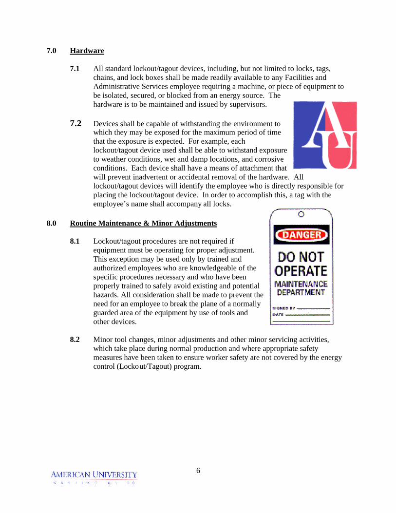
7.1 All standard lockout/tagout devices, including, but not limited to locks, tags, chains, and lock boxes shall be made readily available to any Facilities and Administrative Services employee requiring a machine, or piece of equipment to be isolated, secured, or blocked from an energy source. The hardware is to be maintained and issued by supervisors.
7.2 Devices shall be capable of withstanding the environment to
which they may be exposed for the maximum period of time that the exposure is expected. For example, each lockout/tagout device used shall be able to withstand exposure to weather conditions, wet and damp locations, and corrosive conditions. Each device shall have a means of attachment that will prevent inadvertent or accidental removal of the hardware. All lockout/tagout devices will identify the employee who is directly responsible for placing the lockout/tagout device. In order to accomplish this, a tag with the employee’s name shall accompany all locks.
8.0 Routine Maintenance & Minor Adjustments
8.1 Lockout/tagout procedures are not required if equipment must be operating for proper adjustment. This exception may be used only by trained and authorized employees who are knowledgeable of the specific procedures necessary and who have been properly trained to safely avoid existing and potential hazards. All consideration shall be made to prevent the need for an employee to break the plane of a normally guarded area of the equipment by use of tools and other devices.
8.2 Minor tool changes, minor adjustments and other minor servicing activities,
which take place during normal production and where appropriate safety measures have been taken to ensure worker safety are not covered by the energy control (Lockout/Tagout) program.

7
9.0 Lockout/Tagout Procedures, Sequence and Responsibilities
The following are the minimum procedures to be utilized to place the machinery and equipment in a neutral or zero mechanical state. Specific procedures are developed for each similar type of classification of equipment. Specific procedures are contained in pages 12 through 28. 9.1 Preparation for Shutdown: The authorized employee
will obtain the specific lockout/tagout procedure for the equipment being serviced. The authorized employee will then verify the location of energy isolating devices and complete the energy control documentation form (see page 29).
9.2 Notification: The authorized employee shall notify his or her supervisor, the
information center, central plant operations, and all affected employees that the machinery, equipment or process will be out of service.
9.3 Machine or Equipment Shutdown: The machine or equipment will be secured or shut down using the specific procedures for that specific machine. An orderly shutdown will be utilized to avoid any additional or increased hazards to employees as a result of equipment being de-energized. If the machinery, equipment or process is in operation, follow normal stopping procedures (depress stop button, open toggle switch, etc.). Move switch or levers to "Off" or "Open" positions and close all valves or other energy isolating devices so that the energy source(s) is disconnected or isolated from the machinery or equipment.
9.4 Machine or Equipment Isolation: All energy isolating devices that are needed to
control the energy to the machine or equipment will be physically located and operated in such a manner as to isolate the machine or equipment from the energy source.
9.5 Lockout or Tagout Device Application:
9.5.1 Lockout and/or tagout devices will be affixed to energy isolating devices
by authorized employees. Lockout devices will be affixed in a manner that will hold the energy isolating devices in the "safe" or "off" position. Where tagout devices are used they will be affixed in such a manner that will clearly state that the movement of energy isolating devices from the "safe" or "off" positions is prohibited.

8
9.5.2 Tagout devices will be attached to the same point a
lock would be attached. If the tag cannot be affixed at that point, the tag will be located as close as possible to the device in a position that will be immediately obvious to anyone attempting to operate the device.
9.6 Stored Energy: Following the application of lockout and/or tagout procedures to the energy isolating devices, all potential or residual energy will be relieved, disconnected, restrained, and otherwise rendered safe. Where the re-accumulation of stored energy to a hazardous energy level is possible, verification of isolation will be continued until the maintenance or servicing is complete. Stored energy (capacitors, springs, elevated members, rotating fly wheels, and hydraulic/air/gas/steam systems) must be released, relieved or restrained by grounding, repositioning, blocking and/or bleeding the system.
9.7 Verification of Isolation: Prior to starting work on machines or equipment that
have been locked or tagged out, the authorized employees will verify that isolation or de-energizing the machine or equipment have been accomplished. After ensuring that employees will not be placed in danger, all lockout and tagout measures will be tested by following the normal start up procedures (depress start button, etc.). After testing is completed, place controls in the neutral position.
9.8 Service: Perform the required service.
9.9 Extended Lockout / Tagout: If a shift change will take place before the
machinery or equipment can be restored to service, the lockout/tagout devices must remain. If the task is reassigned to the next shift, those employees must notify the oncoming shift Supervisor and lockout/tagout the devices or equipment before the previous shift may remove their lockout/tagout devices.
9.10 Lockout / Tagout Device Removal: Before lockout and/or tagout devices are
removed and the energy restored to the machine or equipment, the following actions will be taken:
9.10.1 The work area will be thoroughly inspected to ensure that nonessential
items have been removed and that machine or equipment components are operational.
9.10.2 The work area will be checked to ensure that all employees have been
safely positioned or removed. Before the lockout and/or tagout devices are removed, the authorized employee will notify his or her supervisor, the information center, central plant operations, and affected employees.

9
9.10.3 Each lockout and/or tagout device will be
removed from each energy isolating device by the employee who applied the device.
9.10.4 In the event an employee who applied a
lockout/tagout device is not present to remove the device, a supervisor may remove the device by adhering to the following procedure: (Such situations would include an employee leaving work and forgetting to remove his or her lock, or if a piece of equipment is out of service for an extended time and the employee has terminated employment.) 9.10.4.1 Verify that the employee who applied the lock is still an
employee. 9.10.4.2 If the person is still an employee, verify that the employee is not
still working on the equipment by physically checking the work area.
9.10.4.3 Attempt to verify the location of the employee by calling him or her on the radio, or calling him or her at home.
9.10.4.4 Complete the lockout/tagout removal form and forward it to the Assistant Director for Central Plant Operations and the Master Electrician.
9.10.4.5 Thoroughly inspect the work area to ensure that nonessential items have been removed and that machine or equipment components are operational.
9.10.4.6 Ensure that all employees have been safely positioned or removed. Before the lockout and/or tagout devices are removed, the supervisor will notify the information center, central plant operations, and affected employees.
9.11 Outside Contractors: 9.11.1 When an outside contractor conducts maintenance and/or servicing subject
to these lockout/tagout energy control procedures, the contractor shall notify the project manager in writing of the contractors lockout/tagout energy controls procedures.
9.11.2 The project manager will inform the contractor of the University’s
lockout/tagout energy control procedures.
9.11.3 All outside contractors will be notified of this requirement via the contract
or purchase order.

10
10.0 Special Considerations
10.1 Group Lockout/Tagout - When two or more individuals participate in a lockout/tagout energy control operation, each person must apply his/her own lockout/tagout devices.
10.2 Extended Outages/Scheduled Shutdowns - In the event that a piece of
equipment/machine or process must remain out of service because parts are unavailable for repair work to be completed, or items have to be removed and/or sent out for repairs, or additional time is necessary to complete the work, the following precautionary steps shall be taken:
10.2.1 At the end of each scheduled shift, the employee(s) involved shall leave
their personal lock(s)/tag(s) secured.
10.2.2 An employee who has taken the equipment/machinery or process out of service shall notify his or her supervisor, the information center, central plant operations, and all affected employees of the status of the specific outage at the completion of each shift.
11.0 Audits
Periodic audits of this Lockout / Tagout Energy Control Program shall be conducted at least annually to ensure policies and procedures are being followed. If audits reveal inadequacies in Facilities and Administrative Services procedures and/or employee’s lack of knowledge, retraining shall be initiated. The Assistant Director for Central Plant Operations is responsible for ensuring that the audit is completed.
11
Appendix 1 List of Lockout/Tagout Procedures 1. Generic 2. Cord and plug 3. Water treatment 4. Air handling equipment 5. Water pumps 6. Sump Pumps 7. Space heaters 8. Air Compressors 9. A/C units and heat pumps 10. Gas fired hot water heaters 11. Chillers 12. Boilers 13. Electric Hot Water Heaters 14. Water Tanks 15. Gas Furnaces

12
Lockout Tagout Procedure Procedure Number: 01 Equipment: Generic Procedure Step 1 Verify the location of energy isolating devices and the magnitude of the energy. Step 2: Notify the affected employees and work control. Step 3: Shut down by the normal stopping procedure. Step 4: De-activate the energy isolating device(s). Step 5: Lock out the energy isolating device(s) with assigned individual lock(s). Step 6: Dissipate or restrain residual or stored energy. Step 7: Verify the isolation by attempting to start or by testing. Step 8: Perform the service. Step 9: Ensure that nonessential items have been removed and that the equipment is intact. Step 10: Check the work area to ensure that all employees have been safely positioned or removed from the area. Step 11: Verify that the controls are in neutral. Step 12: Remove the lockout devices and reenergize the machine or equipment. Step 13: Notify affected employees.
13
Lockout Tagout Procedure Procedure Number: 02 Equipment: All cord and plug equipment and tools. Step 1: Verify identity of energy sources and isolation devices.
Energy source is 110 volt electric. No isolation device. Cord and plug. This unit might have a starting capacitor.
Step 2: Notify the affected employees. Step 3: Shut down.
Turn off the switch on the unit. Wait until all mechanical parts have stopped moving.
Step 4: De-activate .
Unplug the equipment from the outlet. Step 5: Lock out.
Not necessary to lockout the equipment if it is going to be under your control the entire time. If you must leave the area for any reason, then you must attach your lock and tag to a plug lock on the plug.
Step 6: Dissipate.
Dissipate the capacitor if the unit has one. Step 7: Verify.
Verify that the unit is deenergized by attempting to start the equipment using the on/off switch.
Step 8: Perform the service. Step 9: Ensure that nonessential items have been removed and that the equipment is intact. Step 10: Check the work area to ensure that all employees have been safely positioned or removed from the area. Step 11: Verify that the controls are in neutral or off position. Step 12: Remove the lockout devices and reenergize the machine or equipment. Step 13: Notify affected employees.

14
Lockout Tagout Procedure Procedure Number: 03 Equipment: All water treatment systems . Step 1: Verify location of energy isolating devices and magnitude of energy.
120 volt electricity treatment chemicals water
Step 2: Notify the affected employees and work control. Step 3: Shut down: Shut down the equipment by turning off the switch on the unit. Step 4: De-activate the energy isolating device(s). Unplug the equipment from the outlet. Turn off all water valves Bleed water pressure by cracking open the line Remove chemical suction hose from the container Allow to drain back into the container Step 5: Lock out the energy isolating device(s) with assigned individual lock(s). Not necessary to lockout the equipment if it is going to be under your control the entire time. If you must leave the area for any reason, then you must attach your lock and tag to a plug lock on the plug. Step 6: Dissipate or restrain residual or stored energy. This unit does not have stored or residual energy. Step 7: Verify the isolation by attempting to start or by testing. Verify that the unit is deenergized by attempting to start the equipment using the on/off switch. Step 8: Perform the service. Step 9: Ensure that nonessential items have been removed and that the equipment is intact. Step 10: Check the work area to ensure that all employees have been safely positioned or removed from the area. Step 11: Verify that the on/off switch is in the off position. Step 12: Remove the lockout devices and reenergize the machine or equipment. Step 13: Notify affected employees.

15
Lockout Tagout Procedure Procedure Number: 04 Equipment: Air Handlers Step 1: Verify location of energy isolating devices and the magnitude of energy.
Electric – 120 to 480 volts Starting capacitor (on some units) Hot water Cold water
Step 2: Notify the affected employees and work control. Step 3: Shut down by the normal stopping procedure.
Turn off power at the control point Turn off at breaker or toggle switch if equipped. Wait until fan has stopped moving. Shut off all water valves if necessary (this step usually isn’t necessary)
Step 4: De-activate the energy isolating device(s).
Throw the disconnect to the off position. Step 5: Lock out the energy isolating device(s) with assigned individual lock(s). Step 6: Dissipate or restrain residual or stored energy.
Some fan units have a starting capacitor. Bleed of stored electricity from the capacitor if equipped.
Step 7: Verify the isolation by attempting to start or by testing. Step 8: Perform the service. Step 9: Ensure that nonessential items have been removed and that the equipment is intact. Step 10: Check the work area to ensure that all employees have been safely positioned or removed from the area. Step 11: Verify that the controls are in neutral or off position. Step 12: Remove the lockout devices and reenergize the machine or equipment. Step 13: Notify affected employees.

16
Lockout Tagout Procedure Procedure Number: 05 Equipment: Water Pumps Step 1: Verify location of energy isolating devices and the magnitude of energy.
Most pumps operate on 110 or 220 volt electricity. Some pumps have knife switches for disconnects.
Some pumps may have starting capacitors. Hot water pumps have hot water in and out. Gate or ball valves control water flow. Cold water pumps have cold water in and out. Gate or ball valves control water flow.
Step 2: Notify the affected employees and work control. Step 3: Shut down by the normal stopping procedure.
Turn off the pump by opening the switch closest to the unit. Step 4: De-activate the energy isolating device(s).
If the pump has a knife switch, throw the switch to the off (open) position. Move the breaker to the off (open) position. Close all water valves, in and out.
Step 5: Lock out the energy isolating device(s) with assigned individual lock(s).
Apply lock to knife switch. If not equipped with a knife switch, apply breaker lock to breaker. Apply valve locks to water valves.
Step 6: Dissipate or restrain residual or stored energy.
Dissipate the capacitor. Drain water in lines. Allow hot water lines to cool first.
Step 7: Verify the isolation by attempting to start or by testing. Step 8: Perform the service. Step 9: Ensure that nonessential items have been removed and that the equipment is intact. Step 10: Check the work area to ensure that all employees have been safely positioned or removed from the area. Step 11: Verify that the controls are in neutral or off position.

17
Step 12: Remove the lockout devices and reenergize the machine or equipment. Step 13: Notify affected employees.

18
Lockout Tagout Procedure Procedure Number: 06 Equipment: Sump Pumps Step 1: Verify location of energy isolating devices and the magnitude of energy.
Most units are 120 to 3 phase 480 volt electric cord and plug. Most units have switches operated by a float ball.
Step 2: Notify the affected employees and work control. Step 3: Shut down by the normal stopping procedure.
Make sure toggle switch is in off (open) position. Step 4: De-activate the energy isolating device(s). Unplug the unit. Step 5: Lock out the closest disconnecting energy isolating device(s) with assigned individual lock (s)
Not necessary to lockout the equipment if it is going to be under your control the entire time. If you must leave the area for any reason, then you must attach your lock and tag to a plug lock on the plug.
Step 6: Dissipate or restrain residual or stored energy.
Allow water to drain from the discharge line into the sump pit. Step 7: Verify the isolation by attempting to start or by testing. Step 8: Perform the service. Step 9: Ensure that nonessential items have been removed and that the equipment is intact. Step 10: Check the work area to ensure that all employees have been safely positioned or removed from the area. Step 11: Verify that the controls are in neutral. Step 12: Remove the lockout devices and reenergize the machine or equipment. Step 13: Notify affected employees.

19
Lockout Tagout Procedure Procedure Number: 07 Equipment: Electric space heaters Step 1: Verify location of energy isolating devices and the magnitude of energy. Most heaters operate on 120 or 208 volts electric. Most have toggle switches and breakers. Step 2: Notify the affected employees and work control. Step 3: Shut down by the normal stopping procedure. Turn off the unit by placing the switch or breaker in off (open) position. Step 4: De-activate the energy isolating device(s). Place breaker in off (open) position. Step 5: Lock out the energy isolating device(s) with assigned individual lock(s). Step 6: Dissipate or restrain residual or stored energy. There is no residual energy. Step 7: Verify the isolation by attempting to start or by testing. Step 8: Perform the service. Step 9: Ensure that nonessential items have been removed and that the equipment is intact. Step 10: Check the work area to ensure that all employees have been safely positioned or removed from the area. Step 11: Verify that the controls are in neutral. Step 12: Remove the lockout devices and reenergize the machine or equipment. Step 13: Notify affected employees.
20
Lockout Tagout Procedure Procedure Number: 08 Equipment: Air Compressors Step 1: Verify location of energy isolating devices and the magnitude of energy.
Most air compressors operate on 120 to 480 volts electric. Some compressors have toggle switches, some have push button controls, some have knife switch disconnects. Compressed air in the line.
Step 2: Notify the affected employees and work control. Step 3: Shut down by the normal stopping procedure. Step 4: De-activate the energy isolating device(s).
Throw the breaker to the off (open) position. Throw the d/c to the off (open) position (if equipped).
Step 5: Lock out the energy isolating device(s) with assigned individual lock(s). Step 6: Dissipate or restrain residual or stored energy.
Dissipate the capacitor. Bleed off any air in the line.
Step 7: Verify the isolation by attempting to start or by testing. Step 8: Perform the service. Step 9: Ensure that nonessential items have been removed and that the equipment is intact. Step 10: Check the work area to ensure that all employees have been safely positioned or removed from the area. Step 11: Verify that the controls are in neutral. Step 12: Remove the lockout devices and reenergize the machine or equipment. Step 13: Notify affected employees.
21
Lockout Tagout Procedure Procedure Number: 09 Equipment: A/C Units, Heat Pumps Step 1: Verify location of energy isolating devices and the magnitude of energy. Most A/C units and heat pumps operate on 120 to 3 phase 480 volts electric. Most have starting capacitors. Refrigerant in the lines under pressure. Step 2: Notify the affected employees and work control. Step 3: Shut down by the normal stopping procedure. Step 4: De-activate the energy isolating device(s). Throw knife switch to off (open) position. Throw breaker to off (open) position. Step 5: Lock out the energy isolating device(s) with assigned individual lock(s). Step 6: Dissipate or restrain residual or stored energy.
Dissipate the capacitor. Depending on the work to be performed, refrigerant lines may need to be drained and recovered.
Step 7: Verify the isolation by attempting to start or by testing. Step 8: Perform the service. Step 9: Ensure that nonessential items have been removed and that the equipment is intact. Step 10: Check the work area to ensure that all employees have been safely positioned or removed from the area. Step 11: Verify that the controls are in neutral. Step 12: Remove the lockout devices and reenergize the machine or equipment. Step 13: Notify affected employees.
22
Lockout Tagout Procedure Procedure Number: 10 Equipment: Gas Fired Hot Water Heaters Step 1: Verify location of energy isolating devices and the magnitude of energy.
120 volt electricity Natural gas with gas valves. Some units have electronic ignition. Hot water. Cold water.
Step 2: Notify the affected employees and work control. Step 3: Shut down by the normal stopping procedure. Step 4: De-activate the energy isolating device(s). Turn gas cock to off (closed) position. Throw switch to off (open) position. Turn water valves to off (closed position) Step 5: Lock out the energy isolating device(s) with assigned individual lock(s). Step 6: Dissipate or restrain residual or stored energy.
Bleed any gas. BE SURE THERE ARE NO IGNITION SOURCES NEAR THE UNIT. Bleed off water lines. LET HOT WATER COOL BEFORE BLEEDING.
Step 7: Verify the isolation by attempting to start or by testing. Step 8: Perform the service. Step 9: Ensure that nonessential items have been removed and that the equipment is intact. Step 10: Check the work area to ensure that all employees have been safely positioned or removed from the area. Step 11: Verify that the controls are in neutral. Step 12: Remove the lockout devices and reenergize the machine or equipment. Step 13: Notify affected employees.

23
Lockout Tagout Procedure Procedure Number: 11 Equipment: Chiller Units Step 1: Verify location of energy isolating devices and the magnitude of energy. 120 volt control circuit.
220, 480 or 4160 volt motor current Refrigerant in the lines under pressure. Step 2: Notify the affected employees and work control. Step 3: Shut down by the normal stopping procedure. Step 4: De-activate the energy isolating device(s). Throw knife switch to off (open) position. Throw breaker to off (open) position. Step 5: Lock out the energy isolating device(s) with assigned individual lock(s). Apply tags to all valves, switches, or other isolating devices Step 6: Dissipate or restrain residual or stored energy.
Depending on the work to be performed, refrigerant may need to be recovered. Step 7: Verify the isolation by attempting to start or by testing. Step 8: Perform the service. Step 9: Ensure that nonessential items have been removed and that the equipment is intact. Step 10: Check the work area to ensure that all employees have been safely positioned or removed from the area. Step 11: Verify that the controls are in neutral. Step 12: Remove the lockout devices and reenergize the machine or equipment. Step 13: Notify affected employees.

24
Lockout Tagout Procedure Procedure Number: 12 Equipment: Boilers Step 1: Verify location of energy isolating devices and the magnitude of energy.
Most boilers have 110 volt control circuit and/or pilot ignition. D/C is usually a breaker. Fans can be 110 or 220 volt. Natural gas with ball valves. Fuel oil with OSY’s Hot water with ball valves or OSY Feed water with ball valves or OSY Steam with OSY.
Step 2: Notify the affected employees and work control. Step 3: Shut down by the normal stopping procedure.
This is based on shutdown procedure for boilers 1, 2, and 3 at the main plant. Specific boilers may have different procedures. Stop the burner. Shut off feed water pumps Shut of condensate pumps Shut of makeup valve to condensate pumps Allow time to cool down. Isolate all valves Feed water Condensate Steam stop Gas valves Main Pilot Fuel oil valves Isolate pumps Water feeds Condensate pumps Fuel pumps Turn off control circuit Isolate fans ID FD Unplug water treatment pumps
25
Step 4: De-activate the energy isolating device(s). This was done as part of shutdown procedure. Step 5: Lock out the energy isolating device(s) with assigned individual lock(s).
Apply tags to all valves, switches, or other isolating devices. If boiler is down for the season or for major repair, tags are acceptable. LOCKS MUST BE USED IF BOILER IS DOWN FOR SHORT REPAIR.
Step 6: Dissipate or restrain residual or stored energy. Fans may have capacitors, dissipate capacitors if equipped.
Drain steam, gas, water, oil lines as necessary. Step 7: Verify the isolation by attempting to start or by testing. Step 8: Perform the service. Step 9: Ensure that nonessential items have been removed and that the equipment is intact. Step 10: Check the work area to ensure that all employees have been safely positioned or removed from the area. Step 11: Verify that the controls are in neutral. Step 12: Remove the lockout devices and reenergize the machine or equipment. Step 13: Notify affected employees.
26
Lockout Tagout Procedure Procedure Number: 13 Equipment: Electric hot water heaters Step 1: Verify location of energy isolating devices and the magnitude of energy. Energy is 110 volt electricity Usually only isolating device is a breaker Cold water in – ball or gate valve Hot water out – ball or gate valve Step 2: Notify the affected employees and work control. Step 3: Shut down by the normal stopping procedure. Step 4: De-activate the energy isolating device(s). Step 5: Lock out the energy isolating device(s) with assigned individual lock(s). Step 6: Dissipate or restrain residual or stored energy. Drain water. Step 7: Verify the isolation by attempting to start or by testing. Step 8: Perform the service. Step 9: Ensure that nonessential items have been removed and that the equipment is intact. Step 10: Check the work area to ensure that all employees have been safely positioned or removed from the area. Step 11: Verify that the controls are in neutral. Step 12: Remove the lockout devices and reenergize the machine or equipment. Step 13: Notify affected employees.

27
Lockout Tagout Procedure Procedure Number: 14 Equipment: Water Tanks Step 1: Verify location of energy isolating devices and the magnitude of energy.
Usually the only source of energy will be from water, either hot or cold. Gate, ball, or OSY valves.
Step 2: Notify the affected employees and work control. Step 3: Shut down by the normal stopping procedure. Step 4: De-activate the energy isolating device(s). Close all valves. Allow to cool. Step 5: Lock out the energy isolating device(s) with assigned individual lock(s). Step 6: Dissipate or restrain residual or stored energy. Drain water. Step 7: Verify the isolation by attempting to start or by testing. Step 8: Perform the service. Step 9: Ensure that nonessential items have been removed and that the equipment is intact. Step 10: Check the work area to ensure that all employees have been safely positioned or removed from the area. Step 11: Verify that the controls are in neutral. Step 12: Remove the lockout devices and reenergize the machine or equipment. Step 13: Notify affected employees.

28
Lockout Tagout Procedure Procedure Number: 15 Equipment: Gas Furnace Step 1: Verify location of energy isolating devices and the magnitude of energy. Either 110 or 220 electric. – toggle switches and circuit breakers Natural gas – gas valve Step 2: Notify the affected employees and work control. Step 3: Shut down by the normal stopping procedure. Step 4: De-activate the energy isolating device(s). Step 5: Lock out the energy isolating device(s) with assigned individual lock(s). Step 6: Dissipate or restrain residual or stored energy. Step 7: Verify the isolation by attempting to start or by testing. Step 8: Perform the service. Step 9: Ensure that nonessential items have been removed and that the equipment is intact. Step 10: Check the work area to ensure that all employees have been safely positioned or removed from the area. Step 11: Verify that the controls are in neutral. Step 12: Remove the lockout devices and reenergize the machine or equipment. Step 13: Notify affected employees.

29
Lockout Documentation Form Date . Employee Name . Job Location & #_____________________________________________. Name of equipment/circuit/system being locked out __________________________ . INSTRUCTIONS: Inspect equipment/circuit/system on which the work will be performed. Identify all potential energy sources and lockout capabilities of each source identified. Possible Energy Source Does Source Exist? Can Source be locked out? Chemical Y N Y N Electrical Y N Y N Hydraulic Y N Y N Mechanical Y N Y N Pneumatic Y N Y N Steam Y N Y N Other: specify__________ Y N Y N Comments: ____________________________________________________________ _______________________________________________________________________ I have inspected the above equipment/circuit/system and found the energy sources and lockout conditions as noted above: __________ ____________________ _________ Employee Signature Date Supervisor Signature Date