locking a rubidium oscillator to a remote time …
TRANSCRIPT

40th Annual Precise Time and Time Interval (PTTI) Meeting
527
LOCKING A RUBIDIUM OSCILLATOR TO A REMOTE TIME SCALE USING REAL-TIME
COMMON-VIEW GPS MEASUREMENTS
Michael A. Lombardi Time and Frequency Division
National Institute of Standards and Technology (NIST) Boulder, CO 80305, USA
LTjg. Aaron P. Dahlen Loran Support Unit
United States Coast Guard (USCG) Wildwood, NJ 08260, USA [email protected]
Abstract
This paper introduces a new device, a prototype common-view disciplined oscillator (CVDO) that can be locked to a reference time scale through the use of real-time common-view GPS measurements. A Proportional-Integral-Derivative (PID) controller is used to discipline the oscillator. The PID controller obtains real-time common-view GPS measurements from the Internet at 10-minute intervals, and provides steering corrections to a rubidium oscillator through a serial interface. In principle, the rubidium oscillator can be locked to any time scale that makes real-time common-view data available.
The paper describes the theory of operation of the prototype CVDO, including a
description of the PID controller software. It then presents measurements obtained from a CVDO locked to UTC (NIST), the time scale maintained at the National Institute of Standards and Technology (NIST) in Boulder, Colorado. The paper also describes how a CVDO can emulate other time scales. Results are presented where a CVDO prototype is locked to a time scale located outside of the United States, and then UTC (NIST) is compared to both the original time scale and to the time scale emulator. The paper concludes by discussing some possible applications of CVDOs in metrological and telecommunication areas.
I. INTRODUCTION Real-time timing signals broadcast by radio, such as signals broadcast from the Global Positioning System (GPS) satellites, have long been used to synchronize clocks and syntonize oscillators that are located within the signal’s coverage area. GPS signals that are simultaneously received at two or more sites (common-view) have also long been used to compare clocks or oscillators located at remote sites.

40th Annual Precise Time and Time Interval (PTTI) Meeting
528
Common-view systems require some postprocessing of the data before the measurement results are made available. However, recently developed systems such as the SIM (Interamerican Metrology System) Time network [1] and the NIST Time Measurement and Analysis Service (TMAS) [2] are able to produce common-view measurement results in near real time by utilizing the Internet. This creates new possibilities, because like data received directly from the GPS satellites, near-real-time common-view data can also be used to synchronize clocks and syntonize oscillators. This paper demonstrates this concept and introduces a new device, a common-view disciplined oscillator (CVDO) that can in theory be locked to any reference time scale.
Figure 1. Block diagram of common-view disciplined oscillator system (CVDO).
A block diagram of a prototype CVDO is shown in Figure 1. This system uses two NIST TMAS multi-channel common-view GPS systems. The TMAS implements C/A code, L1-band common view, using low-cost eight-channel GPS receivers. One TMAS unit measures the one pulse per second (1-pps) signal from a master clock; the second TMAS measures the 1-pps signal from a remote clock. Both TMAS units send their measurements via the file transfer protocol (FTP) to an Internet server where the common-view data are processed on the fly, revealing the offset in both time and frequency of the remote clock with respect to the master clock. The computer on the second TMAS system runs Proportional-Integral-Derivative (PID) controller software that obtains the common-view results from the Internet server and sends steering commands through an RS-232 interface that correct the remote clock so that it agrees with the master. The PID controller software is described in detail in Section II.

40th Annual Precise Time and Time Interval (PTTI) Meeting
529
Figure 1 is intentionally generic, because in theory any devices that can generate 1-pps signals can be used as the master and remote clocks, with the remote clock having the additional requirement of a computer interface. However, in practice the master clock will typically be a reference time scale that is traceable to the International System (SI) second, such as UTC (NIST). The remote clock could be a quartz, rubidium, or cesium device. The prototype system uses a rubidium device (Section III), and results from a cesium CVDO experiment are shown in Section VI. II. DESCRIPTION OF PID CONTROLLER SOFTWARE PID controllers are commonly used for applications such as industrial process control, temperature control, and cruise control systems in automobiles, but are seldom mentioned in the time and frequency literature. Perhaps this is because their most likely application is as the control portion of a phase-locked loop (PLL), and the design details are proprietary to the manufacturer and unlikely to be published. However, they are embedded in many time and frequency systems, and a few papers have described the use of PID or proportional-integral (PI) controllers for applications such as the frequency control of a GPS-disciplined oscillator (GPSDO) [3-5], and the jitter reduction of a 1-pps timing signal generated by a GPS clock [6].
A PID controller is the most common control-loop feedback mechanism [7]. Its purpose is to correct the error, e, between a measured process variable (PV) and a desired set point (SP). The PID controller algorithm involves three terms. The P-term determines the reaction to the current error, the I-term determines the reaction based on the sum of recent errors, and the D-term determines the reaction to the rate of change of the error. The weighted sum of these three actions is used to calculate a correction that is applied to the process that is being controlled. The output of the PID-controlled system is the manipulated variable (MV), calculated as
outoutout DIPtMV ++=)( , (1)
where Pout, Iout, and Dout are the contributions to the output from each of the three terms, as defined below.
The P-term makes a change to the output that is proportional to the current error. The P-term is given by
)(teKP pout = , (2)
where Pout is the proportional output, Kp is the proportional gain (a tuning parameter), e is the error (calculated as SP – PV), and t is the time of the current error.
The I-term makes a change to the output that is proportional to both the magnitude of the error and the duration of the error. By integrating the error, the PID controller can account for the accumulated time and frequency offset that should have been corrected previously. The I-term is given by
ττ deKIt
iout )(0∫= , (3)
where Iout is the integral output, Ki is the integral gain (a tuning parameter), e is the error (calculated as SP – PV), and τ is the time in the past that has contributed to the integral response.

40th Annual Precise Time and Time Interval (PTTI) Meeting
530
The D-term is the rate of change of the process error. It can be calculated by determining the slope of the error over time (its first derivative with respect to time) and multiplying this rate of change by the derivative gain:
dttdeKD dout)(
−= , (4)
where Dout is the derivative output, Kd is the derivative gain (a tuning parameter), e is the error (calculated as SP – PV), and t is the instantaneous time [7-10]. A block diagram of a PID controller is shown in Figure 2.
Figure 2. Block diagram of a PID controller.
In the case of the CVDO, the goal is to lock the local oscillator as closely as possible to the reference time scale, which means that the set point (SP) is always 0. The process variable (PV) is the last measured time difference between the local oscillator and the remote time scale. The PID controller software obtains a new value for PV every 10 minutes by activating a common gateway interface (CGI) script on an Internet server that instantly processes the common-view GPS data. The PID controller then uses the hypertext transfer protocol (HTTP) to read the output of the CGI script. Since FTP is used to output raw data and HTTP is used to input processed data, transmission control protocol (TCP) ports 20, 21, and 80 must be open on the local firewall in order for the CVDO to work.
As shown in Equations 2 through 4, each of the three control terms has an associated gain term, Kp, Ki, and Kd, that serve as tuning parameters. The software for the prototype CVDO allows each of the gain parameters to be changed, so that the PID controller can be manually tuned. Tuning the gain parameters changes the speed at which the PID controller responds to errors, the degree to which the controller overshoots the set point, and both the phase noise and stability of the CVDO output. If a gain parameter is set to 0, its associated control term is not used. For example, if Kd is set to 0, the PID controller becomes a PI controller. Our initial tests have shown that inclusion of the D-term does not significantly improve the CVDO’s performance, and more testing is needed to make optimal use of the derivative term. For example, the PID controller software could be enhanced so that it applies the D-term only in specific

40th Annual Precise Time and Time Interval (PTTI) Meeting
531
situations where the negative feedback that it provides is known to improve performance (this is discussed further in Section V).
The display screen of the PID controller software is shown in Figure 3. The screen includes a scrolling window that displays the common-view comparisons (in units of nanoseconds) that have been collected between the CVDO and the remote time scale reference during the past several hours. This window is updated with a new value every 10 minutes. Shortly after the new value is obtained (some delay time is allowed to account for slow network connections), the P, I, and D terms are updated, and a new steering correction is sent to the rubidium oscillator. The screen display is updated to show the new values of the P, I, and D terms, the time of the last steer, and the magnitude of the steering correction. The screen display also calculates the Time deviation (TDEV) [11] at τ = 600 s, using all of the data in the scrolling window.
Figure 3. PID controller display screen.
The PID controller display screen also indicates whether the CVDO is locked or unlocked. The prototype system has two simple requirements that must be met before the CVDO is considered to be locked: the most recent value of PV must be less than 50 ns (indicating accuracy), and the TDEV of the last 20 common-view measurements must be less than 5 ns (indicating stability). If both conditions are met, the PID controller displays a “Locked” message with a green background. If neither condition is met, an “Unlocked” message with a red background is displayed.

40th Annual Precise Time and Time Interval (PTTI) Meeting
532
Once the CVDO is locked, PV values of greater than 50 ns are not used to update the I-term. This simple form of filtering is done to prevent a condition known as integral windup or reset windup. This condition occurs when large, nonlinear errors cause the integral term to become very large or, colloquially, to “wind up” [7,9]. When this happens, the feedback loop is broken and the system will run as an open loop that can wander far from its set point. When the CVDO is unlocked, however, it must be allowed to run as an open loop so that it can eventually return to its set point and relock. Therefore, the 50-ns limit is removed during an unlocked condition, and the I-term limit is set to 2 × PV. Even when the CVDO is unlocked, however, the PID controller limits the maximum allowable frequency change to 5 × 10⁻⁹. Our experience has shown that larger frequency changes can cause the rubidium oscillator to become unstable and behave unpredictably. The PID controller software includes a configuration screen that allows the user to select the serial port used to interface to the rubidium oscillator, to tune the gain parameters, to select the reference time scale (several options are available, including UTC(NIST)), and to select either classic common-view or all-in-view time transfer [12]. The user can also select a steering interval longer than 10 minutes. Although this feature has not been thoroughly tested, it can potentially improve the CVDO’s short-term stability, as discussed in Section III. The local oscillator used for the prototype system is a rubidium device that sells in a rack-mount enclosure for approximately $3000 USD. The device includes a built-in distribution amplifier with six programmable outputs. Each output can produce a frequency output of either 1, 5, or 10 MHz (sine wave or square wave), or a 1-pps timing output. The manufacturer’s aging specification for the rubidium is less than 5 × 10-11 per month. Steering corrections are sent by computer through the serial interface, with a resolution limited to 2 × 10-12. The steering corrections are rounded to match this resolution. All frequency corrections sent to the rubidium must be relative to the “free running factory set” frequency, and not to the last measured frequency. Therefore, the PID controller software saves a log of all corrections. The information in this log is used to reestablish the I-term if power is lost and the controller software is restarted. This allows the CVDO to relock more quickly. More information about the lock acquisition time is provided in Section V. III. CVDO PERFORMANCE Figure 4 is a phase plot of a prototype CVDO locked to UTC (NIST) that is then compared to UTC (NIST). The comparison covers the 40-day period from 10 July through 18 August 2008 (MJD 54657 to 54696). The two GPS antennas are separated by just 36.8 m, so the level of common-view time transfer noise is obviously lower than it would be over a long baseline. As Figure 4 shows, the prototype CVDO closely tracks UTC (NIST). Its timing output was nearly always within ±5 ns of UTC (NIST), with only a few outliers of more than 10 ns. Over the course of the 40-day measurement, the mean time offset of the CVDO with respect to UTC (NIST) was close to the zero set point (~0.2 ns) and the frequency offset was negligible (~1 × 10-16). Figure 5 shows a TDEV graph of the CVDO’s time stability with respect to UTC (NIST). TDEV is near 2 ns at τ = 1 hour, near 0.4 ns at τ = 1 day, and drops below 0.2 ns after an averaging time of several days.

40th Annual Precise Time and Time Interval (PTTI) Meeting
533
Figure 4. Phase plot of CVDO compared to UTC (NIST).
Figure 5. Time Stability of CVDO locked to UTC (NIST).

40th Annual Precise Time and Time Interval (PTTI) Meeting
534
The level of performance demonstrated in Figures 4 and 5 is promising, but further work is planned to try to reduce the amount of phase noise and to improve the short-term stability. One obvious area that can be improved is the filtering of the process variables. A single bad common-view measurement can cause the PID controller to become unlocked or unstable. Some simple safeguards have been added to the software (Section II), but more robust filtering is needed to improve reliability and performance.
Other factors that possibly limit performance are the resolution of the steering corrections, the interval between steering corrections, and the sensitivity of the rubidium oscillator to temperature changes. As noted earlier, the resolution of the rubidium oscillator’s steering corrections is limited to 2 × 10-12, and it would be helpful if finer corrections could be made. However, this is not considered to be a significant problem. Many commercially available GPSDOs work well with devices that have similar or coarser resolution; and the use of a higher-resolution device would increase the CVDO cost. Reducing the interval between steering corrections to less than 10 minutes would require software modifications to the real-time common-view system, because the TMAS units only upload data every 10 minutes. To find out whether a shorter interval would improve performance, we compared the short-term frequency stability of the rubidium oscillator (as measured at NIST) to the short-term stability of a common-clock, common-view GPS comparison between two TMAS units. The Allan deviation (ADEV) was used as the metric, and the results are shown in Figure 6. Note that the x-values of the data points do not line up, since τ0 = 600 s for the common-view data, and the rubidium measurements were obtained with a dual mixer time difference measurement system using a sub-second sampling rate (values where τ is less than 128 s have been omitted from the graph for clarity).
Figure 6. The “crossover” point between local oscillator and time transfer stability.

40th Annual Precise Time and Time Interval (PTTI) Meeting
535
Figure 6 shows that the rubidium stability remains below the level of time transfer noise out to an averaging time of about 1 hour. This indicates that a quieter CVDO output could be obtained by increasing the steering interval to more than 10 minutes. An approximate 60-minute steering interval (the crossover point) might provide the least amount of phase noise, but an interval somewhere between 10 minutes and 60 minutes might provide an optimal mix of reduced phase noise and tightly controlled time synchronization. Poor temperature and humidity control are other factors that might be limiting the performance of the prototype CVDO. This was demonstrated by a test conducted at the Loran Support Unit (LSU) in Wildwood, New Jersey, where a PID controller was used to lock the same model of rubidium used in the prototype to LSU’s cesium ensemble. The top graph shown in Figure 7 shows the phase of the rubidium oscillator’s output during a 10-day period, and the middle and bottom graphs shows the oscillator’s temperature and humidity, respectively, during these same 10 days. During the first 5 days, the rubidium was located in an equipment rack where its temperature fluctuated between 75 and 80°F, leading to phase fluctuations that sometimes exceeded several nanoseconds. To stabilize the temperature, the rubidium was then moved into a plastic box containing a case of water bottles. This change in the rubidium’s location occurred near the midpoint of the Figure 7 graph. After the rubidium was moved, its temperature (as shown in the middle graph) increased by about 10°F, but the temperature range was reduced. The average humidity (bottom graph) dropped by more than 10% and became more stable, but was still subject to some large excursions. The phase data (top graph) showed some obvious improvement, particularly after the rubidium was moved, when the phase amplitude was initially reduced by about 50%. However, there are still some phase fluctuations of two or three nanoseconds that do not correlate exactly with either temperature or humidity variations.
Figure 7. Phase, temperature, and humidity variations of a disciplined rubidium oscillator.

40th Annual Precise Time and Time Interval (PTTI) Meeting
536
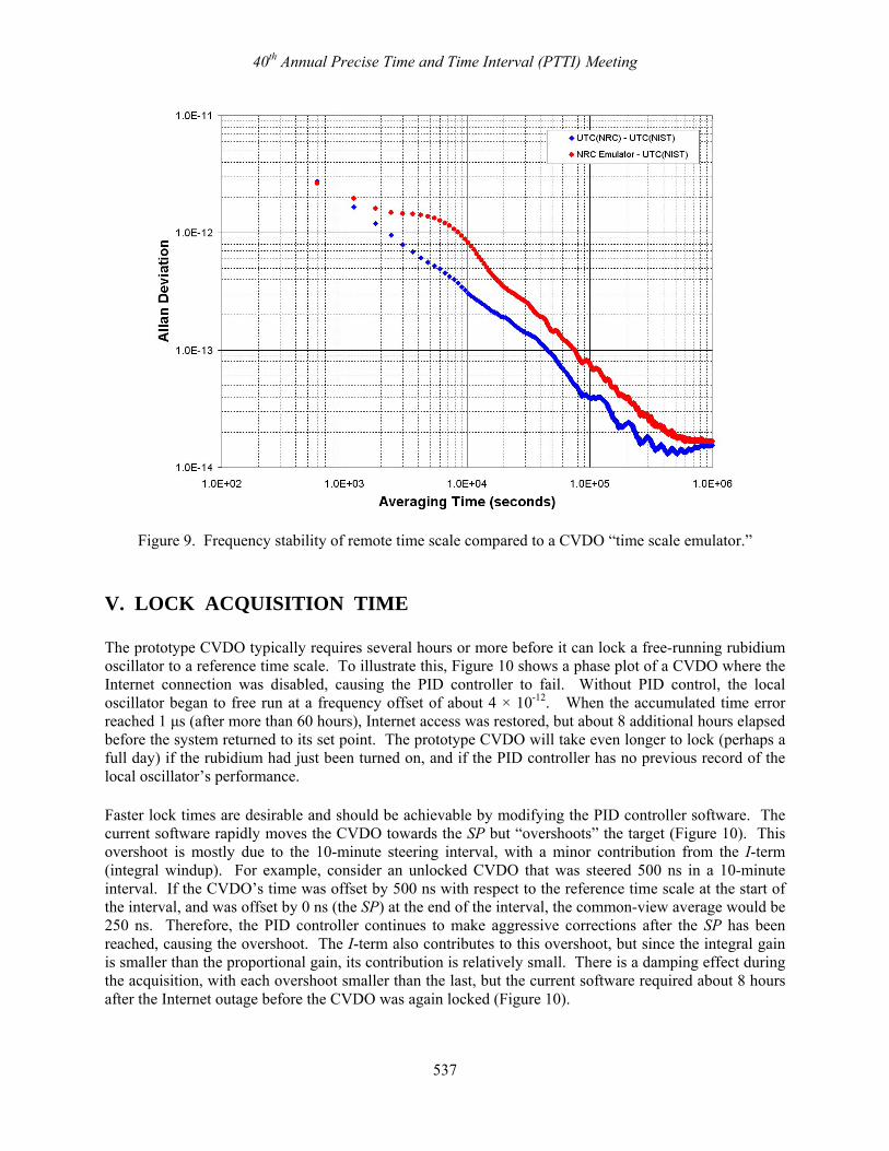
IV. CVDO EMULATION OF A REMOTE TIME SCALE To demonstrate the prototype CVDO’s ability to emulate a reference time scale, a CVDO was locked to UTC (NRC), which is located at the National Research Council (NRC) in Ottawa, Canada. The CVDO was located at NIST in Boulder, about 2199 km from Ottawa. The SIM Time network [1] was then used to simultaneously compare UTC (NIST) both to UTC (NRC) and to the UTC (NRC) emulator. Figure 8 shows a phase plot comparing 1-day averages obtained from both measurements during a 48-day interval (MJD 54735 to 54782). The results shown in Figure 8 show very close agreement, and at first glance, the CVDO performance appears to be equivalent to the reference time scale. However, the all-tau ADEV graph shown in Figure 9 reveals, as expected, that the time scale emulator is less stable than the time scale it is emulating by roughly a factor of two across the range of averaging times. At τ = 1 day, for example, UTC (NRC) has an ADEV of 4.1 × 10⁻¹⁴ with respect to UTC (NIST), as opposed to 7.7 × 10⁻¹⁴ for the CVDO. At τ = 1 hour, the stability difference is still roughly a factor of two, 0.7 × 10⁻¹² for the reference time scale, as opposed to 1.5 × 10⁻¹² for the emulator. The CVDO stability is limited by the instability of its local oscillator, by time transfer noise (which, of course, also affects the direct time scale comparison), and by the other factors discussed in Section III, such as a non-optimal steering interval and temperature fluctuations. We are confident that a “tighter lock” to a reference time scale can be achieved by addressing some of the PID controller issues discussed in Section III, but are encouraged by the prototype’s current level of performance. The frequency stability compares favorably with many GPSDOs [13], and, in principle, a CVDO can be made directly traceable to the reference time scale of any national metrology institute (NMI).
Figure 8. Remote time scale compared to CVDO acting as a time scale “emulator.”
40th Annual Precise Time and Time Interval (PTTI) Meeting
537
Figure 9. Frequency stability of remote time scale compared to a CVDO “time scale emulator.”
V. LOCK ACQUISITION TIME The prototype CVDO typically requires several hours or more before it can lock a free-running rubidium oscillator to a reference time scale. To illustrate this, Figure 10 shows a phase plot of a CVDO where the Internet connection was disabled, causing the PID controller to fail. Without PID control, the local oscillator began to free run at a frequency offset of about 4 × 10-12. When the accumulated time error reached 1 μs (after more than 60 hours), Internet access was restored, but about 8 additional hours elapsed before the system returned to its set point. The prototype CVDO will take even longer to lock (perhaps a full day) if the rubidium had just been turned on, and if the PID controller has no previous record of the local oscillator’s performance.
Faster lock times are desirable and should be achievable by modifying the PID controller software. The current software rapidly moves the CVDO towards the SP but “overshoots” the target (Figure 10). This overshoot is mostly due to the 10-minute steering interval, with a minor contribution from the I-term (integral windup). For example, consider an unlocked CVDO that was steered 500 ns in a 10-minute interval. If the CVDO’s time was offset by 500 ns with respect to the reference time scale at the start of the interval, and was offset by 0 ns (the SP) at the end of the interval, the common-view average would be 250 ns. Therefore, the PID controller continues to make aggressive corrections after the SP has been reached, causing the overshoot. The I-term also contributes to this overshoot, but since the integral gain is smaller than the proportional gain, its contribution is relatively small. There is a damping effect during the acquisition, with each overshoot smaller than the last, but the current software required about 8 hours after the Internet outage before the CVDO was again locked (Figure 10).

40th Annual Precise Time and Time Interval (PTTI) Meeting
538
Figure 10. An example of “overshoot” when the PID controller locks a free-running oscillator. Making better use of the derivative term during the acquisition period might be the key to reducing the lock time. The negative feedback introduced by a properly tuned D-term could potentially reduce the magnitude of the overshoot, forcing the CVDO to lock faster. However, once the CVDO is locked, the software might need to retune the D-term to make it less sensitive to noise in the error term. Otherwise, the derivative gain might amplify the noise to the point where the CVDO output becomes unstable. More work is needed in this area.
VI. A CVDO BASED ON A CESIUM OSCILLATOR
A cesium-based CVDO could be a convenient way to keep a cesium oscillator at a remote location synchronized to a reference time scale, since cesium oscillators have no inherent way of recovering time. In addition, a cesium-based CVDO would have obvious performance advantages over a rubidium device, including: improved stability, less sensitivity to temperature fluctuations, and higher-resolution steering corrections. To see the impact of these advantages, a CVDO experiment was conducted at LSU using a commercially available cesium oscillator with a standard-performance beam tube and an integral phase microstepper that allows steering corrections as fine as 6.3 × 10⁻¹⁵.
The cesium-based CVDO used modified PI controller software that was manually tuned to take advantage of the cesium’s performance characteristics, with the steering interval increased to 1 hour. The common-view data used to steer the device were collected by using a TMAS unit to compare the cesium to UTC (NIST) over a 2588 km baseline. Figure 11 shows the timing stability of the cesium CVDO over a 10-day interval (MJD 54784 to 54793). Note that TDEV is about 0.8 ns at τ values out to 1800 s, which is limited by the transfer noise of the TMAS common-view comparisons over a baseline of this length.

40th Annual Precise Time and Time Interval (PTTI) Meeting
539
Figure 11. Time stability (TDEV) of the LSU cesium-based CVDO compared to UTC (NIST). VII. CVDO RELIABILITY ISSUES Several situations can cause the prototype CVDOs to fail or become unlocked, and refinements to the basic design are needed to make the units more reliable. Like a GPSDO, a CVDO has to deal with the problem of GPS outages due to local interference or other causes. The problem is more pronounced with a CVDO, however, because a GPS failure at either the reference time scale site or the CVDO site can cause a loss of data. And unlike a GPSDO, a CVDO is also vulnerable to Internet outages. An Internet outage at the reference time scale site, the server site, or the CVDO site can prevent new measurement data from being available and force the CVDO to go into holdover mode (Section V). Obviously, no perfect solutions exist for these problems, because if an Internet or GPS outage is long enough, it will eventually cause the CVDO to fail. However, adding additional error trapping routines and “holdover” algorithms to the PID controller software could certainly improve the reliability of the prototype design and make it survive longer outages than it does presently. Another possible enhancement would be to lock the local oscillator to the one-way GPS broadcasts in the event of an Internet outage. VIII. CVDO APPLICATIONS One application for a CVDO is to lock a secondary standard at a calibration or metrology laboratory to the frequency standard of an NMI. NIST is now considering adding the option of a NIST-disciplined oscillator (NISTDO) to its Time Measurement and Analysis Service (TMAS) [2]. This concept was

40th Annual Precise Time and Time Interval (PTTI) Meeting
540
previously demonstrated by researchers in Taiwan, who disciplined remote oscillators via common-view carrier-phase GPS measurements as a means of disseminating traceable frequency [14]. A CVDO service offered by an NMI would allow any subscribing calibration laboratory to locally generate time and frequency signals that are traceable to the SI. Although the performance of an NMI-controlled CVDO is likely to be similar to that of a GPSDO, it could simplify documentation of the traceability chain and perhaps alleviate the concerns of using GPSDOs that are still held by some organizations [13]. A CVDO might also have potential applications in telecommunications systems where a large group of oscillators needs to be synchronized to the same time or syntonized to the same frequency. For example, code division multiple access (CDMA) base stations that support multiple simultaneous channels are required to be synchronized within ±1 μs of each other. They are also required to stay within ±10 μs for periods of up to 8 hours when the external source of timing is disconnected [15]. Figure 10 shows that the prototype CVDO maintained ±1 μs synchronization for more than 60 hours when the Internet connection was disabled, even though no holdover algorithm has been implemented. This rivals or exceeds the holdover performance of many GPSDOs. In addition, the Stratum-1 frequency accuracy requirement of 1 × 10-11 [16,17] should be easily attainable even if a low-cost quartz device is used as the local oscillator. Of course, as mentioned in Section VII, the prototype CVDO is vulnerable to two types of outages, a GPS outage or an Internet outage, which makes it more vulnerable for telecommunications applications than a GPSDO. Therefore, eliminating GPS vulnerability by using a non-GPS common-view signal, such as LORAN or a network timing source, is an intriguing possibility for a future CVDO design. IX. SUMMARY AND CONCLUSIONS A prototype common-view disciplined oscillator (CVDO) system has been designed that can potentially be locked to any time scale that makes real-time common-view data available on the Internet. A PID controller is used to steer the local oscillator. Although the CVDO prototype requires some additional refinement to improve reliability and lock acquisition time, the initial results are promising. CVDOs seem to be natural candidates for deployment in calibration and metrology laboratories, and they might also find applications in telecommunication networks and other areas. X. ACKNOWLEDGMENTS The authors thank the National Research Council (NRC) of Canada for the use of the data shown in Figures 8 and 9. We also thank Tom Parker and Tom Heavner of NIST for their technical review of this manuscript. The identification of commercial products is done for technical completeness only, and implies no endorsement by NIST or USCG. This paper includes contributions from the U.S. government and is not subject to copyright.

40th Annual Precise Time and Time Interval (PTTI) Meeting
541
REFERENCES [1] J. M. Lopez, M. A. Lombardi, A. N. Novick, J-S. Boulanger, R. de Carvalho, R. Solis, and F.
Jimenez, 2008, “The SIM Network: Improved Time Coordination for North, Central, and South America,” in Proceedings of the 22nd European Frequency and Time Forum (EFTF), 23-25 April 2008, Toulouse, France, 9 pp.
[2] M. A. Lombardi and A. N. Novick, 2006, “Remote Time Calibrations via the NIST Time Measurement
and Analysis Service,” Measure: The Journal of Measurement Science, 1, 50-59. [3] R. Hardin and M. Yankowski, 1992, “Performance of a PID Phase Lock Loop with Kalman Filtered
Input Data,” in Proceedings of the 1992 IEEE Frequency Control Symposium (FCS), 27-29 May 1992, Hershey, Pennsylvania, USA (IEEE Publication 92CH3083-3), pp. 238-256.
[4] R. K. Karlquist, L. S. Cutler, E. M. Ingman, J. L. Johnson, and T. Parisek, 1997, “A Low-Profile High-
Performance Crystal Oscillator for Timekeeping Applications,” in Proceedings of the 1997 IEEE International Frequency Control Symposium, 28-30 May 1997, Orlando, Florida, USA (IEEE Publication 97CH36016), pp. 873-884.
[5] B. Shera, 1998, “A GPS-based Frequency Standard,” QST Magazine, 82, 37-44, July 1998. [6] L. Gasparini, O. Zadedyurina, G. Fontana, D. Macii, A. Boni, Y. Ofek, 2007, “A Digital Circuit for
Jitter Reduction of GPS-disciplined 1-pps Synchronization Signals,” in International Workshop on Advanced Methods for Uncertainty Estimation in Measurement (AMUEM), Sardagna, Trento, Italy, 16-18 July 2007, 5 pp.
[7] K. Åström and T. Hägglund, 1995, PID Controllers: Theory, Design, and Tuning (Instrument
Society of America, Research Triangle Park, North Carolina). [8] M. A. Johnson and M. H. Moradi, eds., 2005, PID Control: New Identification and Design
Methods (Springer-Verlag, London). [9] C.-C. Yu, 2006, Autotuning of PID Controllers: A Relay Feedback Approach (Springer-Verlag,
London). [10] A. Dahlen, 2005, “The PID Controller, Parts 1, 2, and 3,” Nuts and Volts, 26, #1, 65-70; #2, 62-68;
& #3, 56-62. [11] “IEEE Standard Definitions of Physical Quantities for Fundamental Frequency and Time Metrology
− Random Instabilities,” IEEE Standard 1139-1999, March 1999. [12] M. A. Lombardi, V. S. Zhang, and R. J. De Carvalho, 2007, “Long Baseline Comparisons of the
Brazilian National Time Scale to UTC (NIST) Using Near Real-Time and Post Processed Solutions,” in Proceedings of the 39th Annual Precise Time and Time Interval (PTTI) Systems and Applications Meeting, 26-29 November 2007, Long Beach, California, USA (U.S. Naval Observatory, Washington, D.C.), pp. 415-426.
[13] M. A. Lombardi, 2008, “The Use of GPS Disciplined Oscillators as Primary Frequency Standards
for Calibration and Metrology Laboratories,” Measure: The Journal of Measurement Science, 3, 56-65.

40th Annual Precise Time and Time Interval (PTTI) Meeting
542
[14] K.-Y. Tu, F.-R. Chang, C.-S. Liao, and L.-S. Wang, 2001, “Frequency Syntonization Using GPS
Carrier Phase Measurements,” IEEE Transactions on Instrumentation and Measurement, IM-50, 833-838.
[15] 3rd Generation Partnership Project 2 (3GPP2), 2004, “Recommended Minimum Performance
Standards for cdma2000 Spread Spectrum Base Stations: Release B,” C.S0010-B, Version 2.0. [16] American National Standard for Telecommunications, 1999, “Synchronization Interface Standards
for Digital Networks,” ANSI T1.101. [17] International Telecommunications Union, 1997, “Timing characteristics of primary reference
clocks,” ITU Recommendation G.811.