lock-n-load ammo plant
TRANSCRIPT

LOCK-N-LOAD®
AMMO PLANT• Auto Progressive (AP™) Reloading Press
• Powder Measure & Case Activated Powder Drop
• Case Feeder
• Pistol Bullet Feeder
OWNER'S MANUAL
Instructional and troubleshooting videos for this product are available on the Hornady website.
Item No. 095160
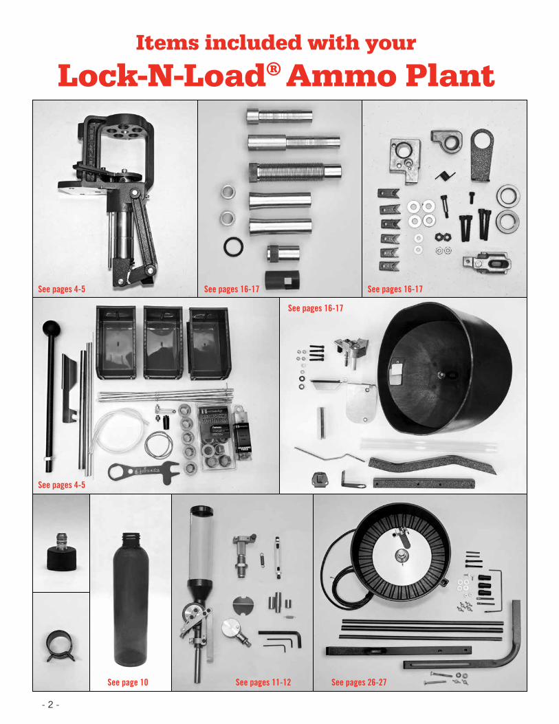
Items included with your
Lock-N-Load® Ammo Plant
See pages 4-5
See pages 4-5
See pages 11-12
See pages 16-17See pages 16-17
See pages 26-27
See pages 16-17
See page 10
- 2 -
Table of ContentsASSEMBLYAP™ Press ....................................................................... Page 4
Powder Measure .............................................................. Page 11
Case Feeder .................................................................... Page 16
Pistol Bullet Feeder .......................................................... Page 26
OPERATIONS .......................................................... Page 34
CHANGE-OVERSThis section covers the selection and installation of the various components needed to change the Ammo Plant from one specific caliber to another.
AP™ Press ....................................................................... Page 38 Shell Plate Die Set Primer Components Primer Slide Primer Tube Primer Punch
Powder Measure .............................................................. Page 40 Changing Powder Metering Insert/Rotor Powder Sleeve/PTX Expander
Case Feeder .................................................................... Page 45 Feed Plate Feed Tube Pivot Adapter/Pivot Adapter Bushing Drop Tube V-Block Adjustments Case Feed Door Adjustment
Pistol Bullet Feeder .......................................................... Page 47 Plate Height Wiper Adjustment Drop Tube Funnel Drop Tube Bullet Feed Die
TROUBLESHOOTINGLock-N-Load® AP™ Press ................................................. Page 50 Shell Plates .................................................................... Page 50
APPENDIXAPPENDIX A Dies & Reloading Essentials Chart ....................................... Page 51APPENDIX B Lock-N-Load® AP™ Press Mounting Template .......................... Page 55
- 3 -

Item No.Production
Part No. Qty. Description1 398318 1 Support Primer Tube
2 398356 1 Tube Primer Pickup, Large
3 398355 1 Tube Primer Pickup, Small
4 398358 1 Tube Primer, Large
5 398357 1 Tube Primer, Small
6 398322 1 Housing Tube Primer
7 392220 1 Screw, BHCS 1/4-20 X 1/2
8 399686 1 Lock-N-Load® AP Bracket
9 392342 1 SHCS SS 3/8-16 X 3/4
10 398359 1 Primer Follower
11 392338 1 Screw, SHCS 10-24 X 1/2
12 — Shell Plate (Sold Separately)
13 392455 1 Bracket Box Cartridge
14 398319A 1 Housing Body Primer Tube
15 392218 1 Primer Slide, Large Assembly
15 392219 1 Primer Slide, Small Assembly
16 392336 1 Spring Primer Slide
17 392363 1 Spring Case Retainer
18 398695 1 AP Breakaway Cam Wire
19 398698 1 Nut, 8-32
20 190216 1 Frame
21 392368 6 Clip C, C-50
22 480039 1 Box Catcher
23 392408 2 Lock-N-Load® AP™ Link
24 398309T 1 Sub Plate
26 398505 1 Primer Seater Punch, Small
26 398507 1 Primer Seater Punch, Large
27 392467 1 Counter Balance Spring
28 392345 1 3/8 Flat Washer SS
29 392355 1 Drive Hub
Item No.Production
Part No. Qty. Description30 392356 1 Drive Shaft
31 392231 2 Screw, BHSCS 8-32 X 3/8
32 392344A 2 Pawl
33 392423 2 Spring Pawl
34 392306 2 Dowel Pin 1/8 X 1/2
35 392221 2 Screw, FHCS 1/4-28 X 3/8
36 290029 1 Spent Primer Tube
37 398163 1 Ram Assembly
38 398422 3 Grease Zerk™
39 392343 1 Toggle
40 392340 1 Pin Yoke
41 392424 5 Spring Washer
42 392417 2 Pin Link Toggle
43 390027 1 Nut Jam, 5/8-18
44 390657 1 Handle
45 480003 1 Knob
47 392358A 1 Index Wheel
48 390081 2 Clip E 1/2
49 392302 5 Lock-N-Load® Bushing, Male
50 392303 5 Lock-N-Load® Bushing O-Ring
51 392301 5 Lock-N-Load® Bushing, Female
52 398697 1 Breakaway Cam Plunger
53 398696 1 Breakaway Cam Wire Spring
54 399853 1 Spent Primer Hose Clamp
55 392365 1 Spent Primer PVC Tube
56 399850 1 Spent Primer Bottle Barbed Fitting
57 399851 1 Spent Primer Bottle Cap
58 399852 1 Spent Primer Bottle
— 9987 1 DVD
Lock-N-Load® Auto Progressive (AP) Reloading Press
PARTS LIST
No-Risk Lifetime WarrantyAll Hornady reloading tools and accessories are warranted against material defects and workmanship for the life of the product. Simply stated – if it breaks, we’ll repair it or replace it at no charge (at Hornady Manufacturing Company’s option).
Hornady reloading tools and accessories are warranted against defective materials and workmanship only. This warranty is void if the product (1) has been damaged by accident or unreasonable use, neglect, improper service or other causes not arising out of defects in material or workmanship; or (2) has been altered or repairs have been made or attempted by other than authorized factory personnel; (3) is used commercially; or (4) has been altered or defaced in any way.
This warranty supersedes all other warranties for Hornady products either written or oral. No other warranty is expressed or implied.
- 4 - ASSEMBLY: AP PRESS
ASSE
MBL
Y

185253
11
1415
1624
2627
35
36
37
344748
48
42 43
44
4140
34 1935
29
17
12
28
9
5
2 3
49
50
257
8
51
20 21
23
22
3132
3338
3945
1
4
6
30
41
10
58
57
55
56
54Lock-N-Load® AP™ Reloading Press
EXPLODED VIEW ASSEMBLY
- 5 -ASSEMBLY: AP PRESS
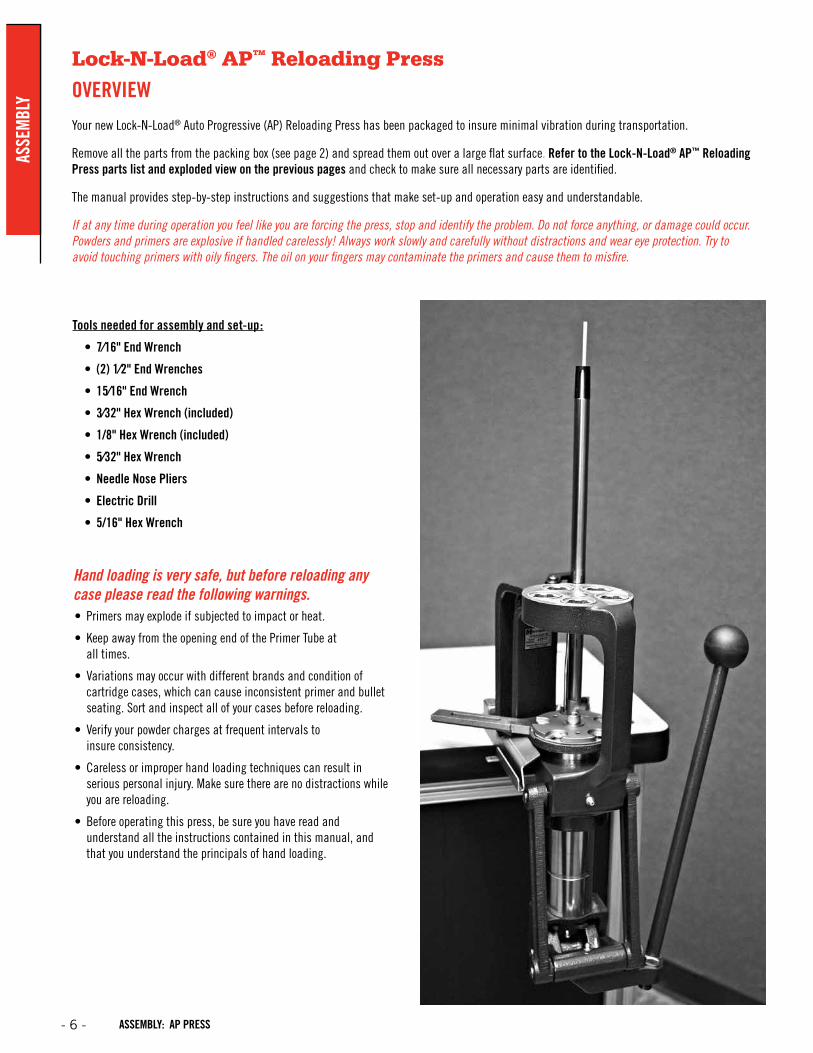
Lock-N-Load® AP™ Reloading Press
OVERVIEW
Your new Lock-N-Load® Auto Progressive (AP) Reloading Press has been packaged to insure minimal vibration during transportation.
Remove all the parts from the packing box (see page 2) and spread them out over a large flat surface. Refer to the Lock-N-Load® AP™ Reloading Press parts list and exploded view on the previous pages and check to make sure all necessary parts are identified.
The manual provides step-by-step instructions and suggestions that make set-up and operation easy and understandable.
If at any time during operation you feel like you are forcing the press, stop and identify the problem. Do not force anything, or damage could occur. Powders and primers are explosive if handled carelessly! Always work slowly and carefully without distractions and wear eye protection. Try to avoid touching primers with oily fingers. The oil on your fingers may contaminate the primers and cause them to misfire.
Hand loading is very safe, but before reloading any case please read the following warnings.• Primers may explode if subjected to impact or heat.
• Keep away from the opening end of the Primer Tube at all times.
• Variations may occur with different brands and condition of cartridge cases, which can cause inconsistent primer and bullet seating. Sort and inspect all of your cases before reloading.
• Verify your powder charges at frequent intervals to insure consistency.
• Careless or improper hand loading techniques can result in serious personal injury. Make sure there are no distractions while you are reloading.
• Before operating this press, be sure you have read and understand all the instructions contained in this manual, and that you understand the principals of hand loading.
Tools needed for assembly and set-up:
• 7⁄16" End Wrench
• (2) 1⁄2" End Wrenches
• 15⁄16" End Wrench
• 3⁄32" Hex Wrench (included)
• 1/8" Hex Wrench (included)
• 5⁄32" Hex Wrench
• Needle Nose Pliers
• Electric Drill
• 5/16" Hex Wrench
- 6 - ASSEMBLY: AP PRESS
ASSE
MBL
Y
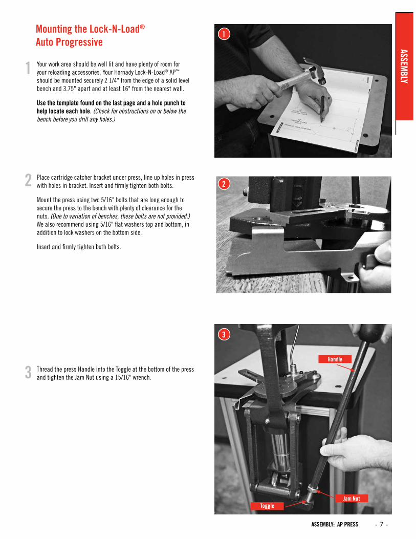
Mounting the Lock-N-Load® Auto Progressive
Your work area should be well lit and have plenty of room for your reloading accessories. Your Hornady Lock-N-Load® AP™ should be mounted securely 2 1/4" from the edge of a solid level bench and 3.75" apart and at least 16" from the nearest wall.
Use the template found on the last page and a hole punch to help locate each hole. (Check for obstructions on or below the bench before you drill any holes.)
Place cartridge catcher bracket under press, line up holes in press with holes in bracket. Insert and firmly tighten both bolts.
Mount the press using two 5/16" bolts that are long enough to secure the press to the bench with plenty of clearance for the nuts. (Due to variation of benches, these bolts are not provided.) We also recommend using 5/16" flat washers top and bottom, in addition to lock washers on the bottom side.
Insert and firmly tighten both bolts.
Thread the press Handle into the Toggle at the bottom of the press and tighten the Jam Nut using a 15/16" wrench.
1
2
3
1
2
3Handle
Jam NutToggle
ASSEMBLY
- 7 -ASSEMBLY: AP PRESS
4
5
6
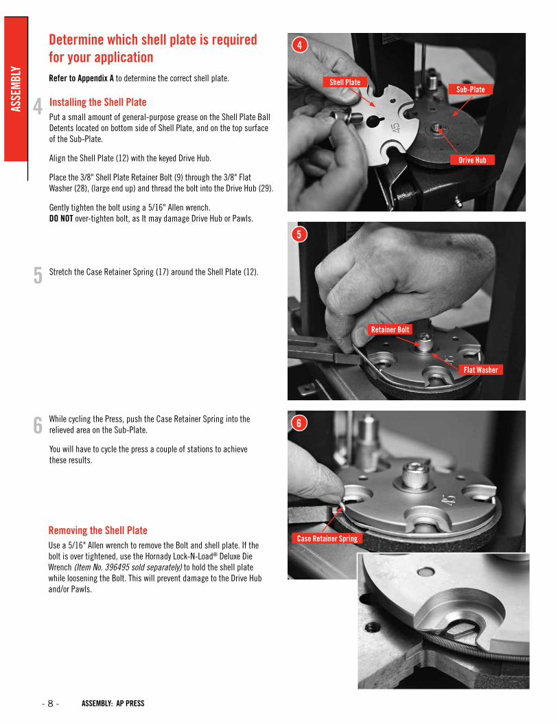
Determine which shell plate is required for your applicationRefer to Appendix A to determine the correct shell plate.
Installing the Shell PlatePut a small amount of general-purpose grease on the Shell Plate Ball Detents located on bottom side of Shell Plate, and on the top surface of the Sub-Plate.
Align the Shell Plate (12) with the keyed Drive Hub.
Place the 3/8" Shell Plate Retainer Bolt (9) through the 3/8" Flat Washer (28), (large end up) and thread the bolt into the Drive Hub (29).
Gently tighten the bolt using a 5/16" Allen wrench. DO NOT over-tighten bolt, as It may damage Drive Hub or Pawls.
Stretch the Case Retainer Spring (17) around the Shell Plate (12).
While cycling the Press, push the Case Retainer Spring into the relieved area on the Sub-Plate.
You will have to cycle the press a couple of stations to achieve these results.
Removing the Shell PlateUse a 5/16" Allen wrench to remove the Bolt and shell plate. If the bolt is over tightened, use the Hornady Lock-N-Load® Deluxe Die Wrench (Item No. 396495 sold separately) to hold the shell plate while loosening the Bolt. This will prevent damage to the Drive Hub and/or Pawls.
4
5
Shell Plate
Retainer Bolt
Sub-Plate
Flat Washer
Drive Hub
Case Retainer Spring
6
- 8 - ASSEMBLY: AP PRESS
ASSE
MBL
Y
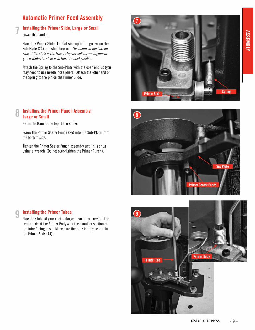
Automatic Primer Feed Assembly Installing the Primer Slide, Large or SmallLower the handle.
Place the Primer Slide (15) flat side up in the groove on the Sub-Plate (24) and slide forward. The bump on the bottom side of the slide is the travel stop as well as an alignment guide while the slide is in the retracted position.
Attach the Spring to the Sub-Plate with the open end up (you may need to use needle nose pliers). Attach the other end of the Spring to the pin on the Primer Slide.
Installing the Primer Punch Assembly, Large or SmallRaise the Ram to the top of the stroke.
Screw the Primer Seater Punch (26) into the Sub-Plate from the bottom side.
Tighten the Primer Seater Punch assembly until it is snug using a wrench. (Do not over-tighten the Primer Punch).
Installing the Primer TubesPlace the tube of your choice (large or small primers) in the center hole of the Primer Body with the shoulder section of the tube facing down. Make sure the tube is fully seated in the Primer Body (14).
7
8
Primer Slide Spring
Primer Seater Punch
Sub Plate
9
7
8
9
Primer TubePrimer Body
ASSEMBLY
- 9 -ASSEMBLY: AP PRESS
10
Primer Tube Housing
11
Primer Tube Support
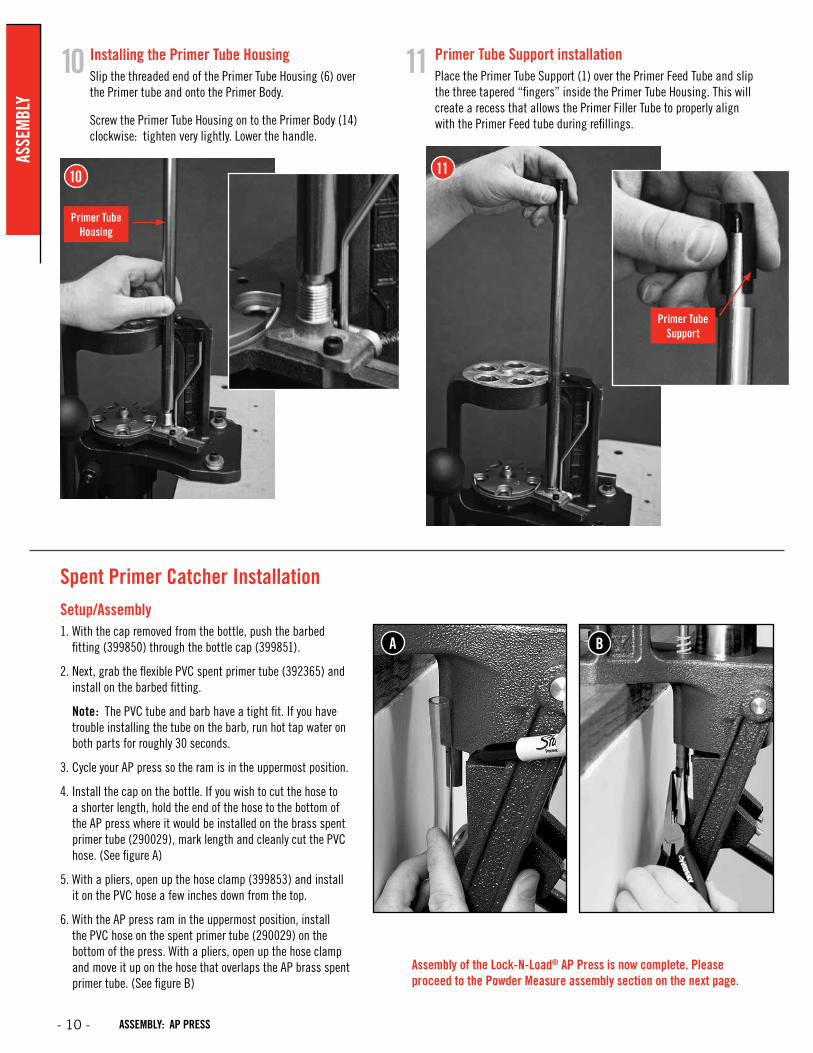
Installing the Primer Tube HousingSlip the threaded end of the Primer Tube Housing (6) over the Primer tube and onto the Primer Body.
Screw the Primer Tube Housing on to the Primer Body (14) clockwise: tighten very lightly. Lower the handle.
Primer Tube Support installationPlace the Primer Tube Support (1) over the Primer Feed Tube and slip the three tapered “fingers” inside the Primer Tube Housing. This will create a recess that allows the Primer Filler Tube to properly align with the Primer Feed tube during refillings.
10 11
Assembly of the Lock-N-Load® AP Press is now complete. Please proceed to the Powder Measure assembly section on the next page.
Spent Primer Catcher Installation Setup/Assembly1. With the cap removed from the bottle, push the barbed
fitting (399850) through the bottle cap (399851).
2. Next, grab the flexible PVC spent primer tube (392365) and install on the barbed fitting.
Note: The PVC tube and barb have a tight fit. If you have trouble installing the tube on the barb, run hot tap water on both parts for roughly 30 seconds.
3. Cycle your AP press so the ram is in the uppermost position.
4. Install the cap on the bottle. If you wish to cut the hose to a shorter length, hold the end of the hose to the bottom of the AP press where it would be installed on the brass spent primer tube (290029), mark length and cleanly cut the PVC hose. (See figure A)
5. With a pliers, open up the hose clamp (399853) and install it on the PVC hose a few inches down from the top.
6. With the AP press ram in the uppermost position, install the PVC hose on the spent primer tube (290029) on the bottom of the press. With a pliers, open up the hose clamp and move it up on the hose that overlaps the AP brass spent primer tube. (See figure B)
A B
- 10 - ASSEMBLY: AP PRESS
ASSE
MBL
Y
Item No.
Production Part Number
Qty. Description
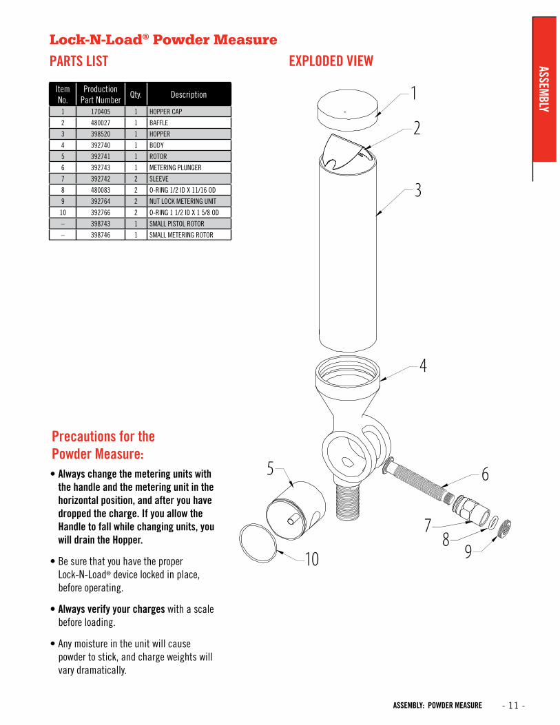
1 170405 1 HOPPER CAP
2 480027 1 BAFFLE
3 398520 1 HOPPER
4 392740 1 BODY
5 392741 1 ROTOR
6 392743 1 METERING PLUNGER
7 392742 2 SLEEVE
8 480083 2 O-RING 1/2 ID X 11/16 OD
9 392764 2 NUT LOCK METERING UNIT
10 392766 2 O-RING 1 1/2 ID X 1 5/8 OD
– 398743 1 SMALL PISTOL ROTOR
– 398746 1 SMALL METERING ROTOR
1
2
3
5
10 98
7
6
4
Lock-N-Load® Powder Measure
PARTS LIST EXPLODED VIEW
Precautions for the Powder Measure:• Always change the metering units with
the handle and the metering unit in the horizontal position, and after you have dropped the charge. If you allow the Handle to fall while changing units, you will drain the Hopper.
• Be sure that you have the proper Lock-N-Load® device locked in place, before operating.
• Always verify your charges with a scale before loading.
• Any moisture in the unit will cause powder to stick, and charge weights will vary dramatically.
ASSEMBLY
- 11 -ASSEMBLY: POWDER MEASURE
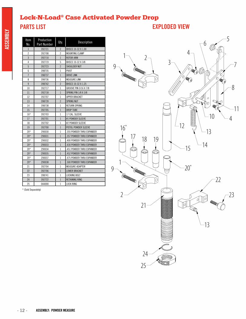
Lock-N-Load® Case Activated Powder Drop
PARTS LIST EXPLODED VIEW
Item No.
Production Part Number
Qty. Description
1 392721 2 BHSCS 10-32 X 1.00
2 392708 2 MOUNTING CLAMP
3 392710 1 ROTOR ARM
4 392719 5 BHSCS 10-32 X 3/8
5 392723 2 SHOULDER NUT
6 398735 1 PIVOT
7 398737 1 DRIVE LINK
8 398736 1 MEASURE LINK
9 398742 2 BHSCS 10-32 X 1.25
10 392717 1 GROOVE PIN 3/16 X 7/8
11 392718 1 SPRING PIN 1/8 X 3/8
12 392707 1 UPPER BRACKET
13 398739 2 SPRING NUT
14 398738 1 RETURN SPRING
15 392705 1 DROP TUBE
16* 392703 1 17 CAL. SLEEVE
17 392701 1 #1 POWDER SLEEVE
18 392702 1 #2 POWDER SLEEVE
19 392700 1 PISTOL POWDER SLEEVE
20* 290030 1 .355 POWDER THRU EXPANDER
20* 290031 1 .357 POWDER THRU EXPANDER
20* 290032 1 .400 POWDER THRU EXPANDER
20* 290033 1 .430 POWDER THRU EXPANDER
20* 290034 1 .451 POWDER THRU EXPANDER
20* 290035 1 .452 POWDER THRU EXPANDER
20* 290037 1 .475 POWDER THRU EXPANDER
20* 290038 1 .500 POWDER THRU EXPANDER
21 392704 1 MEASURE ADAPTER
22 392706 1 LOWER BRACKET
23 398741 1 LOCKING BOLT
24 392722 1 RETAINING RING
25 O44000 1 LOCK RING
* (Sold Separately)
65
7
8
11410
13
14
12
15
20*
22
23
13
21
24
25
2
91
16*
17 18 19
9
1 23
4
- 12 -
ASSE
MBL
Y
ASSEMBLY: POWDER MEASURE
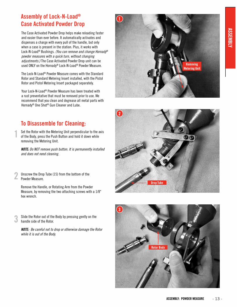
The Case Activated Powder Drop helps make reloading faster and easier than ever before. It automatically activates and dispenses a charge with every pull of the handle, but only when a case is present in the station. Plus, it works with Lock-N-Load® Bushings. (You can remove and change Hornady®
powder measures with a quick turn, without changing adjustments.) The Case Activated Powder Drop unit can be used ONLY on the Hornady® Lock-N-Load® Powder Measure.
The Lock-N-Load® Powder Measure comes with the Standard Rotor and Standard Metering Insert installed, with the Pistol Rotor and Pistol Metering Insert packaged separately.
Your Lock-N-Load® Powder Measure has been treated with a rust preventative that must be removed prior to use. We recommend that you clean and degrease all metal parts with Hornady® One Shot® Gun Cleaner and Lube.
To Disassemble for Cleaning:
Slide the Rotor out of the Body by pressing gently on the handle side of the Rotor.
NOTE: Be careful not to drop or otherwise damage the Rotor while it is out of the Body.
Unscrew the Drop Tube (15) from the bottom of the Powder Measure.
Remove the Handle, or Rotating Arm from the Powder Measure, by removing the two attaching screws with a 1/8" hex wrench.
Set the Rotor with the Metering Unit perpendicular to the axis of the Body, press the Push Button and hold it down while removing the Metering Unit.
NOTE: Do NOT remove push button. It is permanently installed and does not need cleaning.
1
2
3
1
2
3
Removing Metering Unit
Drop Tube
Rotor Body
Assembly of Lock-N-Load® Case Activated Powder Drop ASSEM
BLY
- 13 -ASSEMBLY: POWDER MEASURE
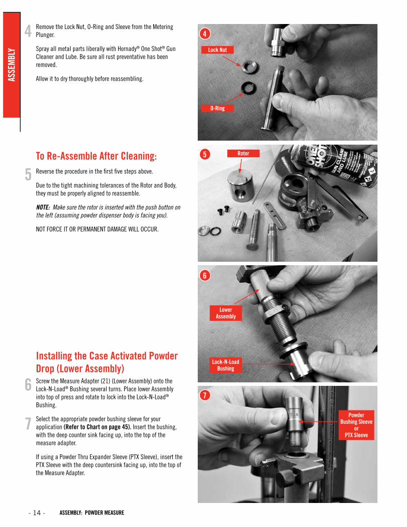
Remove the Lock Nut, O-Ring and Sleeve from the Metering Plunger.
Spray all metal parts liberally with Hornady® One Shot® Gun Cleaner and Lube. Be sure all rust preventative has been removed.
Allow it to dry thoroughly before reassembling.
To Re-Assemble After Cleaning:Reverse the procedure in the first five steps above.
Due to the tight machining tolerances of the Rotor and Body, they must be properly aligned to reassemble.
NOTE: Make sure the rotor is inserted with the push button on the left (assuming powder dispenser body is facing you).
NOT FORCE IT OR PERMANENT DAMAGE WILL OCCUR.
Installing the Case Activated Powder Drop (Lower Assembly)Screw the Measure Adapter (21) (Lower Assembly) onto the Lock-N-Load® Bushing several turns. Place lower Assembly into top of press and rotate to lock into the Lock-N-Load® Bushing.
Select the appropriate powder bushing sleeve for your application (Refer to Chart on page 45). Insert the bushing, with the deep counter sink facing up, into the top of the measure adapter.
If using a Powder Thru Expander Sleeve (PTX Sleeve), insert the PTX Sleeve with the deep countersink facing up, into the top of the Measure Adapter.
Lock-N-LoadBushing
Powder Bushing Sleeve
or PTX Sleeve
4
5
6
7
4
5
6
7
Lock Nut
O-Ring
LowerAssembly
Rotor
- 14 -
ASSE
MBL
Y
ASSEMBLY: POWDER MEASURE
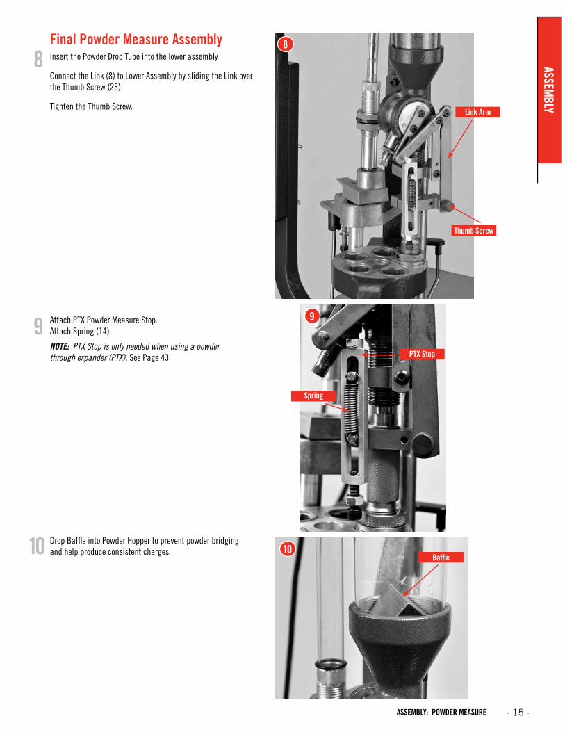
Final Powder Measure Assembly Insert the Powder Drop Tube into the lower assembly
Connect the Link (8) to Lower Assembly by sliding the Link over the Thumb Screw (23).
Tighten the Thumb Screw.
Drop Baffle into Powder Hopper to prevent powder bridging and help produce consistent charges.
Attach PTX Powder Measure Stop. Attach Spring (14).
NOTE: PTX Stop is only needed when using a powder through expander (PTX). See Page 43.
10
9
8
10
9
8
PTX Stop
Thumb Screw
Link Arm
Spring
Baffle
ASSEMBLY
- 15 -ASSEMBLY: POWDER MEASURE

Item No.Production
Part No. Qty. Description1 398441 1 Case Feed Bowl
2 398313 4 10-32 x ¾ FHSCS
4 398445 4 8-32 x 3/4 Screw
5 398443 1 Case Feed Funnel Front
6 398375 2 4-40 Hex Head Lock Nut
7 399630 1 Micro Switch
8 398442 1 Case Feed Funnel Back
9 398376 2 4-40 x 5/8 BHSCS
10 398332 1 Rocker Switch
11 398331 1 Motor
12 398444 1 Motor Cover
13 398320 1 Feed Tube - Large
14 398321 1 Feed Tube - Small
15 398303 1 Feed Tube End Primary
16 398446 1 Feed Tube Mounting Bracket
17 396440 2 Lock Ring
18 398298 1 Pivot Adapter
19 398290 1 Pivot
20 398310 1 1/4 - 3/4 Shoulder Bolt
21 398311 1 3/0 x 3/4 Taper Pin
22 398305 1 Drop Tube - Large
23 398288 1 Spring, Torsion
24 398317 1 Push Rod
25 398371 1 Push Rod Tip
26 390178 6 1/4-20 Hex Head Nut
27 398349 1 Push Rod Bushing
28 398364 1 10 x 1/2 Sheet Metal Screw Pan Head Phillips
29 398344 1 Pivot Body
30 398363 1 Push Rod Spring
31 398343 1 Cam Wire Support
32 398425 1 E Clip 1/4
34 398372 1 Push Rod Lower
37 398285 1 Case Feed Door Adjustment
38 398291 1 Case Slide
39 398307 1 Case Slide Rod Guide
40 398308 1 Case Slide Rod Guide Spring
Item No.Production
Part No. Qty. Description41 392011 2 10-32 Hex Head Nut
42 398289 1 Main Bracket
43 398299 1 Cam Wire
47 398321 2 1/4-20 x 1.25 SHCS
48 390128 4 1/4 Flat Washer Zinc Plated
49 392031 2 1/4" Lock Washer
50 398360 1 Feed Tube Insert - Small
51 398300 1 Pivot Adapter Bushing
52 398301 1 Pivot Bushing
53 398306 1 Drop Tube-Small
54 095310 * Case Feed Plate - Small Pistol
55 095312 * Case Feed Plate - Large Pistol
56 095314 * Case Feed Plate - Small Rifle
57 095316 * Case Feed Plate - Large Rifle
58 059100 * AP Press
59 398346 1 10-24 x 1/2 SHCS
60 398293 1 V-Block #1
61 398297 1 V-Block #2
62 398294 1 V-Block #3
63 398292 1 V-Block #4
64 398295 1 V-Block #5
65 398296 1 V-Block #6
66 398324 1 Plastic Feed Tube Small Bushing
67 390651 2 3/16" Flat Washer SAE
68 390410 1 10-24 x 1/4 BHCS
69 398370 1 Case Feed Bowl Bushing
70 398388 4 1/4-20 x 1.50 SHCS
71 398416 1 O-Ring 7/8 OD, 11/16 ID
73 398361 1 Feed Tube Insert - Intermediate
74 398447 1 Case Feeder Stand 2-PC Upper
75 398449 1 1" Square Tube Connector
76 398448 1 Case Feeder Stand 2-PC Lower
77 399677 1 Case Feeder Tip Stop
78 399691 1 Cam Block Clamp
79 399730 1 ¼-20 X 1.75 SHCS
* Optional Accessories: Sold Separately
Lock-N-Load® Auto Progressive (AP™) Case Feeder
PARTS LIST
- 16 -
ASSE
MBL
Y
ASSEMBLY: CASE FEEDER
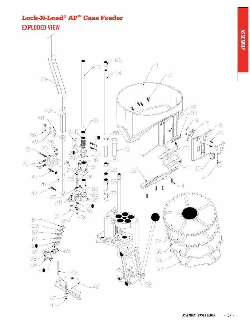
Lock-N-Load® AP™ Case Feeder
EXPLODED VIEW ASSEMBLY
- 17 -ASSEMBLY: CASE FEEDER

Lock-N-Load® AP™ Case Feeder
OVERVIEWYour new AP™ Case Feeder has been packaged to insure minimal vibration and damage during transportation.
Remove all the parts from the packing box (see page 2) and spread them out over a large flat surface. Refer to the Lock-N-Load® Case Feeder parts list and exploded view on the next two pages to make sure all necessary parts are identified.
The manual provides step-by-step instructions and suggestions that make set-up and operation easy and understandable.
NOTE: Everything is designed and machined to fit easily together without modification. If you find that it is necessary to force parts together, stop and check the instructions and illustrations we have provided.
List of needed hand tools:• 3/8" wrench
• 7/16" wrench
• 9/16" wrench
• 1/8" Allen wrench
• 5/32" Allen wrench
• 3/16" Allen wrench
• Pliers or vise grips
• Small hammer
2
1
2
1
Assembling the 2-pc Square Tubing.Place Lower Case Feeder Stand next to mounting holes on the back of the AP™ press to determine proper orientation of the Lower Case Feeder Stand. Once the “top” of the Lower Case Feeder Stand has been determined, place the Lower Case Feeder Stand onto a block of scrap wood. Next insert the Tube Connector into the Lower Case Feeder Stand until the holes align. Place the Feed Tube Mounting Bracket onto the Lower Case Feeder Stand so the Feed Tube Mounting bracket is on the open end of the Tube Connector (see photo). Place a ¼-20 x 1.5" bolt through the Feed Tube Mounting bracket and Lower Case Feeder Stand and loosely attach the flat washer, lock washer, and nut.
Place Upper Case Feeder Stand over the Tube Connector until it touches the Lower Case Feeder Stand. Place a ¼-20 x 1.5" bolt through the Feed Tube Mounting bracket and Upper Case Feeder Stand and securely attach the flat washer, lock washer, and nut. Tighten the lower nut in the Lower Case Feeder Stand.
Attach assembly onto AP™ Press.
Tube connector Upper Case Feeder Stand
Feed Tube Mounting Bracket
Tube connector
INCORRECT ASSEMBLY
CORRECT ASSEMBLY
Lower Case
Feeder Stand
If your AP™ press has a cartridge box bracket that mounts on top of the press, it will need to be changed out for the Main Bracket (42). To do this, unbolt the press from the bench top, remove the old cartridge box bracket, and slide the new Main Bracket under the press so the two raised holes fit into the press mounting holes (see exploded view for correct orientation). Re-mount the press to the bench top using the same hardware that was previously used to bolt the press down.
- 18 -
ASSE
MBL
Y
ASSEMBLY: CASE FEEDER
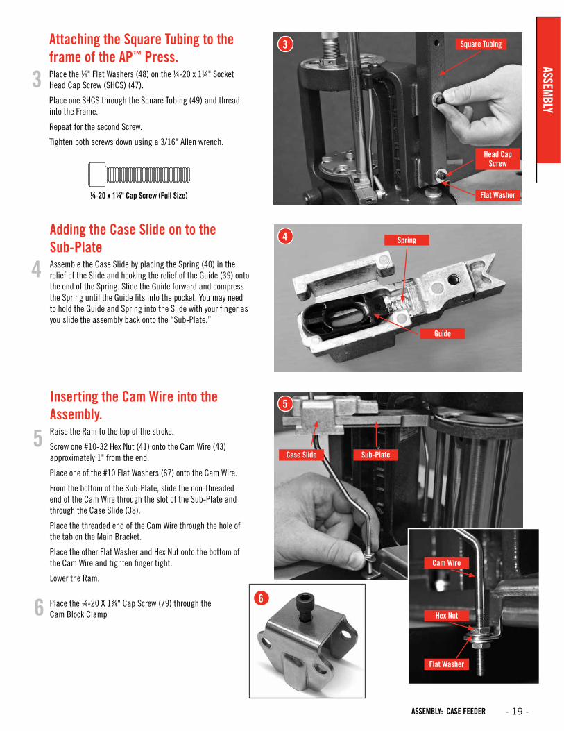
Cam Wire
Hex Nut
Flat Washer
¼-20 x 1¼" Cap Screw (Full Size)
5
4
5
6
4
Attaching the Square Tubing to the frame of the AP™ Press.Place the ¼" Flat Washers (48) on the ¼-20 x 1¼" Socket Head Cap Screw (SHCS) (47).
Place one SHCS through the Square Tubing (49) and thread into the Frame.
Repeat for the second Screw.
Tighten both screws down using a 3/16" Allen wrench.
3
3
Head Cap Screw
Flat Washer
Square Tubing
Inserting the Cam Wire into the Assembly.Raise the Ram to the top of the stroke.
Screw one #10-32 Hex Nut (41) onto the Cam Wire (43) approximately 1" from the end.
Place one of the #10 Flat Washers (67) onto the Cam Wire.
From the bottom of the Sub-Plate, slide the non-threaded end of the Cam Wire through the slot of the Sub-Plate and through the Case Slide (38).
Place the threaded end of the Cam Wire through the hole of the tab on the Main Bracket.
Place the other Flat Washer and Hex Nut onto the bottom of the Cam Wire and tighten finger tight.
Lower the Ram.
Guide
Case Slide Sub-Plate
Spring
Place the ¼-20 X 1¾" Cap Screw (79) through the Cam Block Clamp6
Adding the Case Slide on to the Sub-PlateAssemble the Case Slide by placing the Spring (40) in the relief of the Slide and hooking the relief of the Guide (39) onto the end of the Spring. Slide the Guide forward and compress the Spring until the Guide fits into the pocket. You may need to hold the Guide and Spring into the Slide with your finger as you slide the assembly back onto the “Sub-Plate.”
ASSEMBLY
- 19 -ASSEMBLY: CASE FEEDER
7
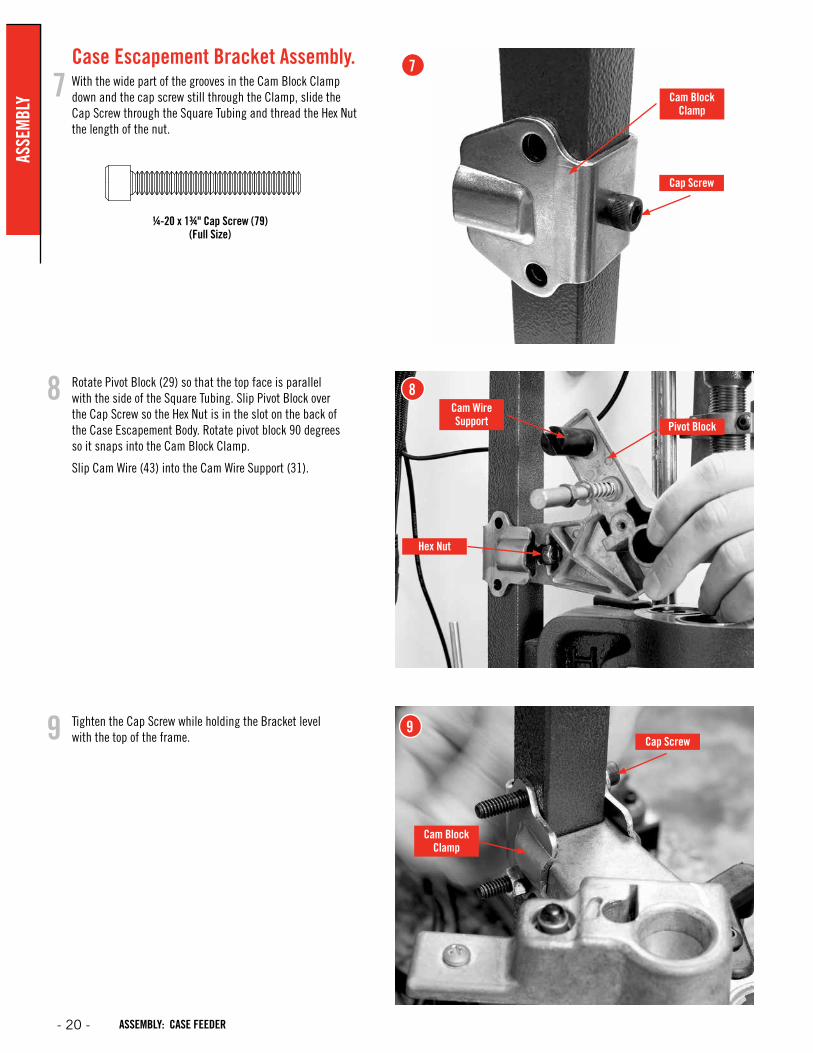
8Cam Wire Support Pivot Block
Cap Screw
Cap Screw
Cam Block Clamp
Cam Block Clamp
Hex Nut
¼-20 x 1¾" Cap Screw (79) (Full Size)
9
Case Escapement Bracket Assembly. With the wide part of the grooves in the Cam Block Clamp down and the cap screw still through the Clamp, slide the Cap Screw through the Square Tubing and thread the Hex Nut the length of the nut.
Rotate Pivot Block (29) so that the top face is parallel with the side of the Square Tubing. Slip Pivot Block over the Cap Screw so the Hex Nut is in the slot on the back of the Case Escapement Body. Rotate pivot block 90 degrees so it snaps into the Cam Block Clamp.
Slip Cam Wire (43) into the Cam Wire Support (31).
7
8
9 Tighten the Cap Screw while holding the Bracket level with the top of the frame.
- 20 -
ASSE
MBL
Y
ASSEMBLY: CASE FEEDER
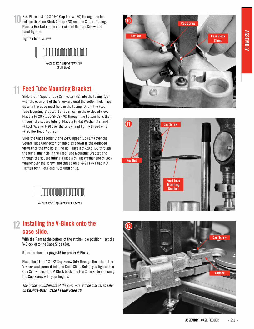
Installing the V-Block onto the case slide.With the Ram at the bottom of the stroke (idle position), set the V-Block onto the Case Slide (38).
Refer to chart on page 45 for proper V-Block.
Place the #10-24 X 1/2 Cap Screw (59) through the hole of the V-Block and screw it into the Case Slide. Before you tighten the Cap Screw, push the V-Block back into the Case Slide and snug the Cap Screw with your fingers.
The proper adjustments of the cam wire will be discussed later on Change-Over: Case Feeder Page 46.
11
12 12
V-Block
Cap Screw
¼-20 x 1½" Cap Screw (Full Size)
11
Feed Tube Mounting Bracket
Hex Nut
Cap Screw
Feed Tube Mounting Bracket.Slide the 1" Square Tube Connector (75) into the tubing (76) with the open end of the V forward until the bottom hole lines up with the uppermost hole in the tubing. Orient the Feed Tube Mounting Bracket (16) as shown in the exploded view. Place a ¼-20 x 1.50 SHCS (70) through the bottom hole, then through the square tubing. Place a ¼ Flat Washer (48) and ¼ Lock Washer (49) over the screw, and lightly thread on a ¼-20 Hex Head Nut (26).
Slide the Case Feeder Stand 2-PC Upper tube (74) over the Square Tube Connector (oriented as shown in the exploded view) until the two holes line up. Place a ¼-20 SHCS through the remaining hole in the Feed Tube Mounting Bracket and through the square tubing. Place a ¼ Flat Washer and ¼ Lock Washer over the screw, and thread on a ¼-20 Hex Head Nut. Tighten both Hex Head Nuts until snug.
7.5. Place a ¼-20 X 1½” Cap Screw (70) through the top hole on the Cam Block Clamp (78) and the Square Tubing. Place a Hex Nut on the other side of the Cap Screw and hand tighten.
Tighten both screws.
¼-20 x 1½" Cap Screw (70) (Full Size)
10 10
Hex Nut
Cap Screw
Cam Block Clamp
ASSEMBLY
- 21 -ASSEMBLY: CASE FEEDER
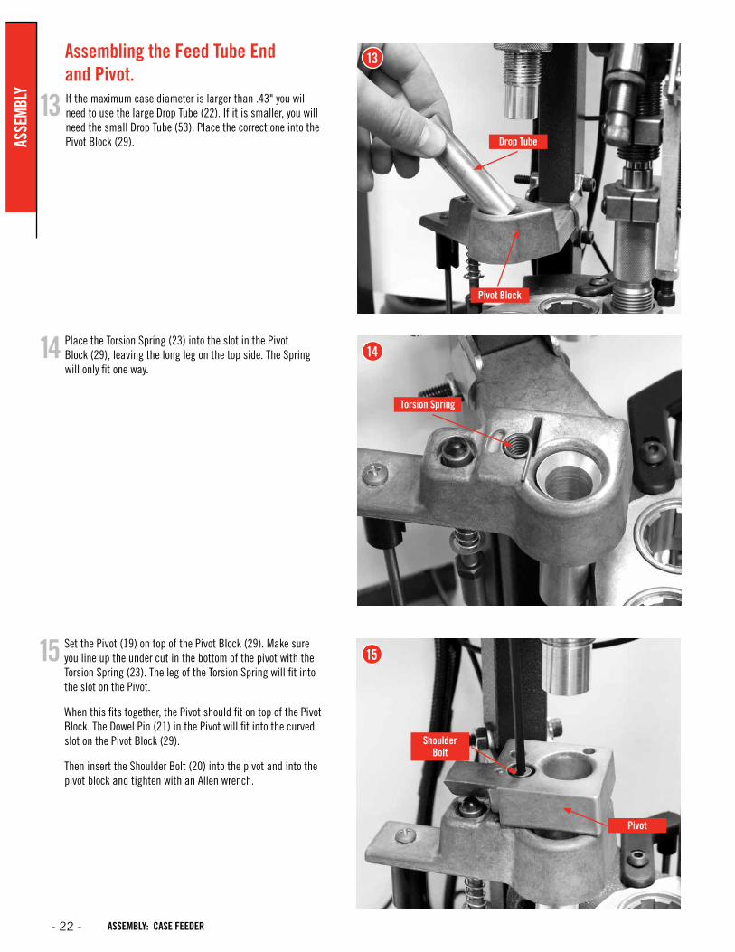
Assembling the Feed Tube End and Pivot.If the maximum case diameter is larger than .43" you will need to use the large Drop Tube (22). If it is smaller, you will need the small Drop Tube (53). Place the correct one into the Pivot Block (29).
14
13
Place the Torsion Spring (23) into the slot in the Pivot Block (29), leaving the long leg on the top side. The Spring will only fit one way.
Set the Pivot (19) on top of the Pivot Block (29). Make sure you line up the under cut in the bottom of the pivot with the Torsion Spring (23). The leg of the Torsion Spring will fit into the slot on the Pivot.
When this fits together, the Pivot should fit on top of the Pivot Block. The Dowel Pin (21) in the Pivot will fit into the curved slot on the Pivot Block (29).
Then insert the Shoulder Bolt (20) into the pivot and into the pivot block and tighten with an Allen wrench.
15
14
Torsion Spring
13
Drop Tube
Pivot Block
15
Shoulder Bolt
Pivot
- 22 -
ASSE
MBL
Y
ASSEMBLY: CASE FEEDER
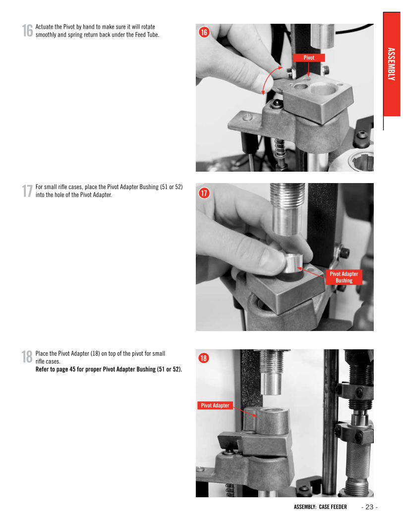
Actuate the Pivot by hand to make sure it will rotate smoothly and spring return back under the Feed Tube.
For small rifle cases, place the Pivot Adapter Bushing (51 or 52) into the hole of the Pivot Adapter.
16
17
16
17
Pivot Adapter Bushing
Pivot
Pivot Adapter
Place the Pivot Adapter (18) on top of the pivot for small rifle cases. Refer to page 45 for proper Pivot Adapter Bushing (51 or 52).
18 18
ASSEMBLY
- 23 -ASSEMBLY: CASE FEEDER

Feed Tube End
Push Rod
Feed Tube
20
20
19
19
Feed Tube End
Placing the Feed Tube End on the Assembly.
Lock Ring
Select the proper Feed Tube and insert it in the top of the Feed Tube End. If you select the Small Feed Tube, you will have to use the Plastic Feed Tube Small Bushing (66). Refer to page 45.
(When feeding some cases, such as the 357 Mag, you may notice that the base of the case will not fall into the hole of the Pivot every time. The base will ride on the radius of the pivot hole. This is correct because when the Push Rod starts to rotate the Pivot, the case will fall into the hole.)
Screw one Lock Ring (17) on the Feed Tube End Primary.
Place it through the hole on the Feed Tube Mounting Bracket (16). Determine whether a Feed Tube Insert is necessary. (Refer to Page 45). If so, place the insert inside of the Feed Tube End Primary. Adjust the height of the Feed Tube End to have approximately 1/16" below the bottom of the tube to the case mouth. With some cases such as the 357 Mag, it may be necessary to adjust the Feed Tube End to where the case mouth sits up inside of the Feed Tube End. These are both starting points, and for your particular case, it may need to be adjusted a little differently. (Long skinny cases, which are shorter than 1.50" long, will not work with the Pivot Adapter.) They may need to be supported at the mouth of the case by the Feed Tube Ends. This will allow the case to feed down the Drop Tubes without falling over and causing double or triple feeds.
Screw on the other Lock Ring (17).
Feed Tube Bushing
SmallFeed Tube
- 24 -
ASSE
MBL
Y
ASSEMBLY: CASE FEEDER
Placing the Feed Bowl Hopper on the Assembly
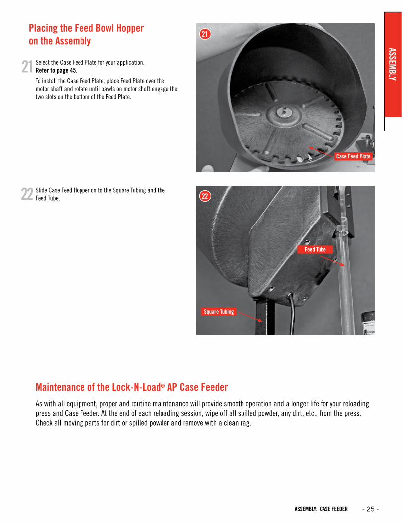
Select the Case Feed Plate for your application. Refer to page 45.
To install the Case Feed Plate, place Feed Plate over the motor shaft and rotate until pawls on motor shaft engage the two slots on the bottom of the Feed Plate.
Slide Case Feed Hopper on to the Square Tubing and the Feed Tube.22
21
22
Square Tubing
Case Feed Plate
Feed Tube
Maintenance of the Lock-N-Load® AP Case FeederAs with all equipment, proper and routine maintenance will provide smooth operation and a longer life for your reloading press and Case Feeder. At the end of each reloading session, wipe off all spilled powder, any dirt, etc., from the press. Check all moving parts for dirt or spilled powder and remove with a clean rag.
21
ASSEMBLY
- 25 -ASSEMBLY: CASE FEEDER

Item No.Production
Part No. Qty. Description
1 392011 3 Nut Hex 10-32 Zinc
2 399209 1 Steel Knurled Thumb Screw
3 399213 1 Tube Spring Clamp
4 399210 1 BHCS 10-32 X 1/4
5 399214 1 Tube Bullet Drop Funnel Large
5 399215 1 Tube Bullet Drop Funnel Medium
5 399216 1 Tube Bullet Drop Funnel Small
6 399205 1 Screw Adjustment Bullet Feed
7 399206 1 Screw Lock Nut Adjustment
8 398067 1 Rubber Washer Flat
9 399208 1 Center Plate Adjustment Nut
10 398400 1 Thumb Screw 1/4-20 X 1/2
11 399202 1 Hopper Turning Plate
12 398401 2 Screw FHSCS 10-32 X 1/4
13 399201 1 Bullet Feed Wheel - Pistol
14 399212 3 Nut Hex 1/4-20
15 399207 1 Center Pin Bullet Plate
16 399218 1 Spur Gear 1.500 P.D., 30 Tooth
17 398313 8 Screw FHSCS 10-32 X 3/4
18 399203 1 Bullet Feeder Base Plate
19 398402 1 Ideler Gear Shaft
Item No.Production
Part No. Qty. Description
20 399102 1 Spur Gear 1.200 P.D. 24 Tooth
21 399244 1 FHCS 1/4-20 X 1/2
22 398381 1 Pin Spirol 1/8 X 3/4
23 398399 1 Motor Bullet Feeder
24 399222 2 Screw Bullet Wiper
25 399242 6 Nut Wing 1/4-20
26 399223 2 Spring Wiper Bullet Feed
27 399224 2 Thumb Screw 8-32 X 1/2
28 399217 1 Tube Holder Bullet Feeder
29 399200 1 Bullet Feed Hopper
30 399211 2 SHCS 1/4-20 X 2
31 390128 6 Washer Flat 1/4"
32 398418 1 Bushing (HEYCO 1147) Black
33 399219 1 Tube Drop Small
33 399243 1 Tube Drop Medium
33 399221 1 Tube Drop Large
34 398332 1 Switch 2 Position
36 399358 1 Support Tube-Bottom
37 399359 1 Support Tube-Top
38 399360 2 1" Square Finishing Plug
39 399362 2 1/4-20x2.5 Carriage Bolt
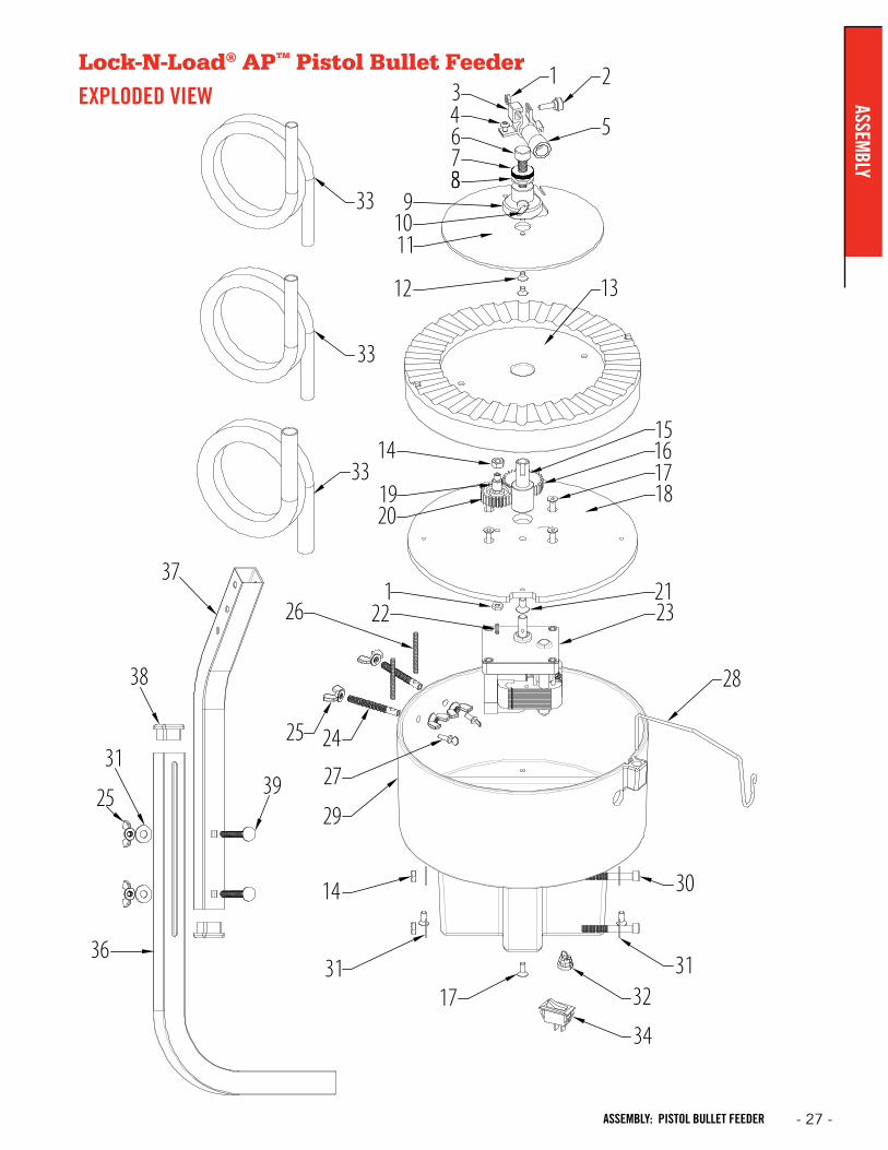
Lock-N-Load® Auto Progressive (AP™) Pistol Bullet Feeder
PARTS LIST
- 26 -
ASSE
MBL
Y
ASSEMBLY: PISTOL BULLET FEEDER
Lock-N-Load® AP™ Pistol Bullet Feeder
EXPLODED VIEW ASSEMBLY
- 27 -ASSEMBLY: PISTOL BULLET FEEDER
Lock-N-Load® AP™ Pistol Bullet Feeder
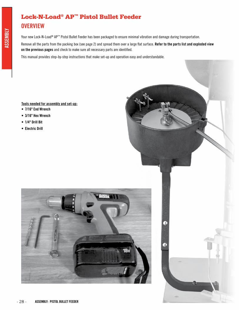
OVERVIEW
Your new Lock-N-Load® AP™ Pistol Bullet Feeder has been packaged to ensure minimal vibration and damage during transportation.
Remove all the parts from the packing box (see page 2) and spread them over a large flat surface. Refer to the parts list and exploded view on the previous pages and check to make sure all necessary parts are identified.
This manual provides step-by-step instructions that make set-up and operation easy and understandable.
Tools needed for assembly and set-up:• 7/16" End Wrench
• 3/16" Hex Wrench
• 1/4" Drill Bit
• Electric Drill
- 28 -
ASSE
MBL
Y
ASSEMBLY: PISTOL BULLET FEEDER
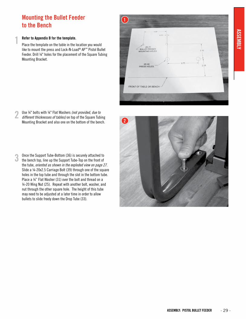
Mounting the Bullet Feeder to the Bench
Refer to Appendix B for the template.
Place the template on the table in the location you would like to mount the press and Lock-N-Load® AP™ Pistol Bullet Feeder. Drill ¼" holes for the placement of the Square Tubing Mounting Bracket.
Use ¼" bolts with ¼" Flat Washers (not provided, due to different thicknesses of tables) on top of the Square Tubing Mounting Bracket and also one on the bottom of the bench.
Once the Support Tube-Bottom (36) is securely attached to the bench top, line up the Support Tube-Top on the front of the tube, oriented as shown in the exploded view on page 27. Slide a ¼-20x2.5 Carriage Bolt (39) through one of the square holes in the top tube and through the slot in the bottom tube. Place a ¼” Flat Washer (31) over the bolt and thread on a ¼-20 Wing Nut (25). Repeat with another bolt, washer, and nut through the other square hole. The height of this tube may need to be adjusted at a later time in order to allow bullets to slide freely down the Drop Tube (33).
1
2
3
1
2
ASSEMBLY
- 29 -ASSEMBLY: PISTOL BULLET FEEDER
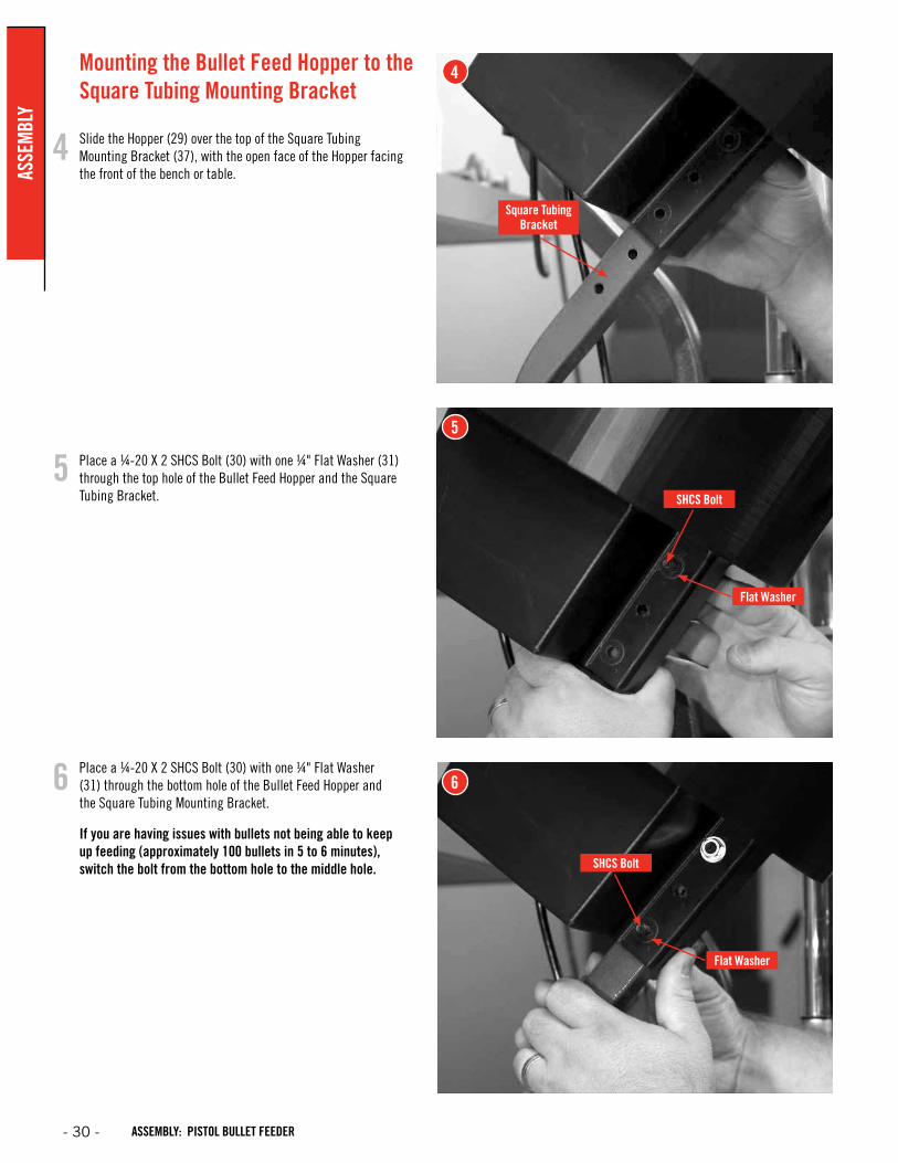
Place a ¼-20 X 2 SHCS Bolt (30) with one ¼" Flat Washer (31) through the bottom hole of the Bullet Feed Hopper and the Square Tubing Mounting Bracket.
If you are having issues with bullets not being able to keep up feeding (approximately 100 bullets in 5 to 6 minutes), switch the bolt from the bottom hole to the middle hole.
Slide the Hopper (29) over the top of the Square Tubing Mounting Bracket (37), with the open face of the Hopper facing the front of the bench or table.
Place a ¼-20 X 2 SHCS Bolt (30) with one ¼" Flat Washer (31)through the top hole of the Bullet Feed Hopper and the Square Tubing Bracket.
Mounting the Bullet Feed Hopper to the Square Tubing Mounting Bracket
4
5
6
Flat Washer
Flat Washer
SHCS Bolt
SHCS Bolt
4
5
6
Square Tubing Bracket
- 30 -
ASSE
MBL
Y
ASSEMBLY: PISTOL BULLET FEEDER
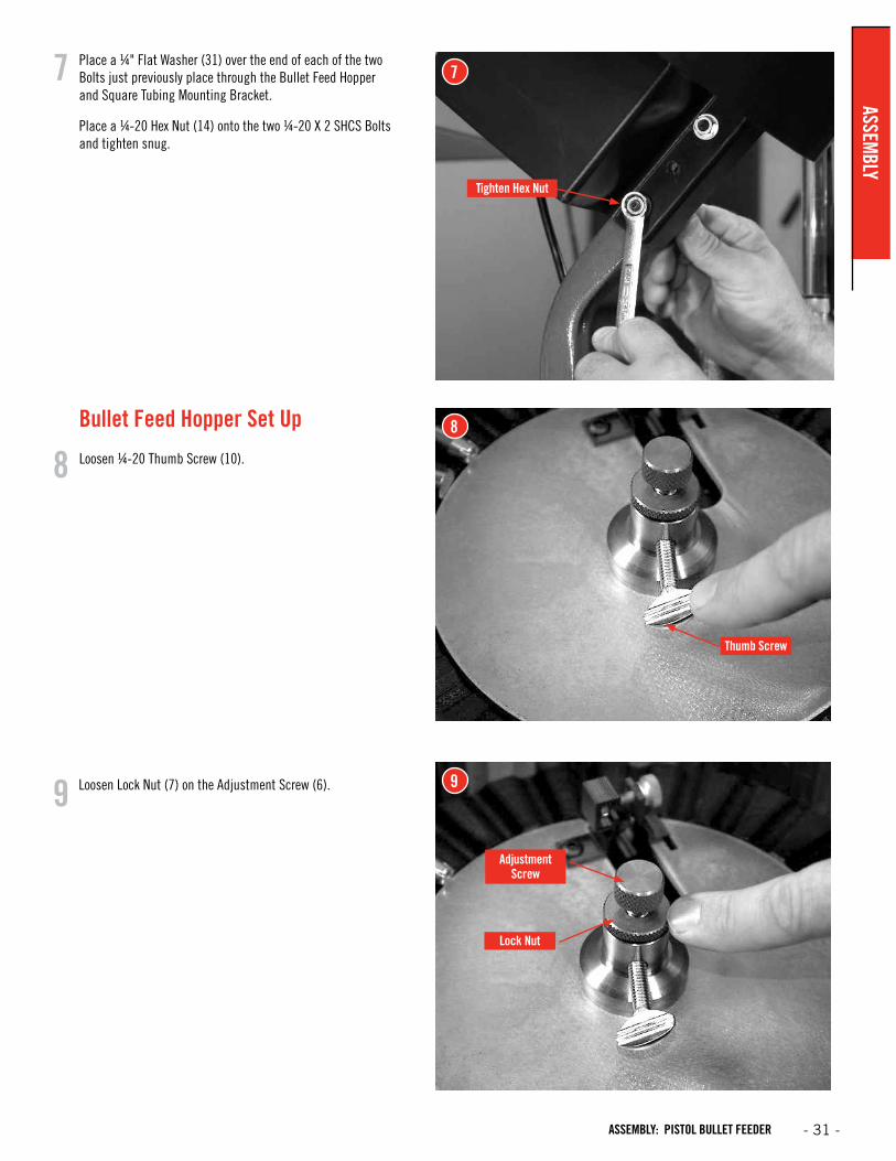
Place a ¼" Flat Washer (31) over the end of each of the two Bolts just previously place through the Bullet Feed Hopper and Square Tubing Mounting Bracket.
Place a ¼-20 Hex Nut (14) onto the two ¼-20 X 2 SHCS Bolts and tighten snug.
Bullet Feed Hopper Set Up
Loosen ¼-20 Thumb Screw (10).
Loosen Lock Nut (7) on the Adjustment Screw (6).
7
8
9
Tighten Hex Nut
Lock Nut
Thumb Screw
7
8
9
Adjustment Screw
ASSEMBLY
- 31 -ASSEMBLY: PISTOL BULLET FEEDER
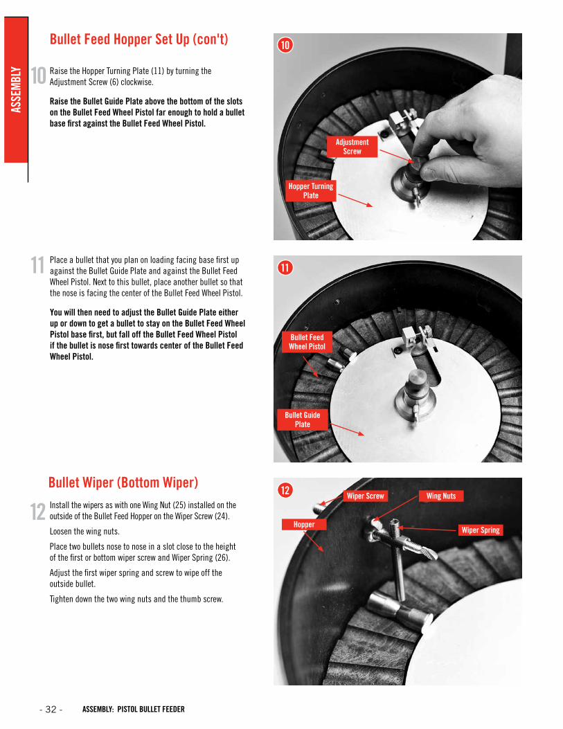
Install the wipers as with one Wing Nut (25) installed on the outside of the Bullet Feed Hopper on the Wiper Screw (24).
Loosen the wing nuts.
Place two bullets nose to nose in a slot close to the height of the first or bottom wiper screw and Wiper Spring (26).
Adjust the first wiper spring and screw to wipe off the outside bullet.
Tighten down the two wing nuts and the thumb screw.
Bullet Wiper (Bottom Wiper)
Raise the Hopper Turning Plate (11) by turning the Adjustment Screw (6) clockwise.
Raise the Bullet Guide Plate above the bottom of the slots on the Bullet Feed Wheel Pistol far enough to hold a bullet base first against the Bullet Feed Wheel Pistol.
Place a bullet that you plan on loading facing base first up against the Bullet Guide Plate and against the Bullet Feed Wheel Pistol. Next to this bullet, place another bullet so that the nose is facing the center of the Bullet Feed Wheel Pistol.
You will then need to adjust the Bullet Guide Plate either up or down to get a bullet to stay on the Bullet Feed Wheel Pistol base first, but fall off the Bullet Feed Wheel Pistol if the bullet is nose first towards center of the Bullet Feed Wheel Pistol.
Bullet Feed Hopper Set Up (con't)
Wiper Screw
Hopper
Wing Nuts
Wiper Spring
10
11
12
10
11
12
Adjustment Screw
Hopper Turning Plate
Bullet Guide Plate
Bullet Feed Wheel Pistol
- 32 -
ASSE
MBL
Y
ASSEMBLY: PISTOL BULLET FEEDER
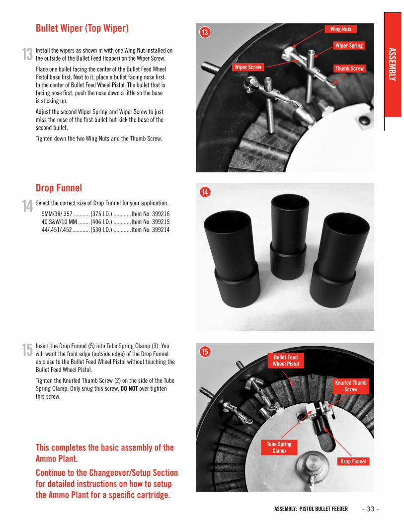
Insert the Drop Funnel (5) into Tube Spring Clamp (3). You will want the front edge (outside edge) of the Drop Funnel as close to the Bullet Feed Wheel Pistol without touching the Bullet Feed Wheel Pistol.
Tighten the Knurled Thumb Screw (2) on the side of the Tube Spring Clamp. Only snug this screw, DO NOT over tighten this screw.
Install the wipers as shown in with one Wing Nut installed on the outside of the Bullet Feed Hopper) on the Wiper Screw.
Place one bullet facing the center of the Bullet Feed Wheel Pistol base first. Next to it, place a bullet facing nose first to the center of Bullet Feed Wheel Pistol. The bullet that is facing nose first, push the nose down a little so the base is sticking up.
Adjust the second Wiper Spring and Wiper Screw to just miss the nose of the first bullet but kick the base of the second bullet.
Tighten down the two Wing Nuts and the Thumb Screw.
Select the correct size of Drop Funnel for your application.
9MM/38/.357 ........... (375 I.D.) ............ Item No. 399216 40 S&W/10 MM ........ (406 I.D.) ............ Item No. 399215 .44/.451/.452 ............ (530 I.D.) ............ Item No. 399214
Drop Funnel
This completes the basic assembly of the Ammo Plant.
Continue to the Changeover/Setup Section for detailed instructions on how to setup the Ammo Plant for a specific cartridge.
Bullet Wiper (Top Wiper)
Wiper Screw Thumb Screw
Wiper Spring
Drop Funnel
Wing Nuts
13
14
15
13
14
15
Tube Spring Clamp
Bullet Feed Wheel Pistol
Knurled Thumb Screw
ASSEMBLY
- 33 -ASSEMBLY: PISTOL BULLET FEEDER

The Hornady Lock-N-Load® AP™ utilizes a high strength aluminum alloy frame with a compound linkage system which operates the 2" diameter cylindrical ram. The Ram houses a drive shaft that is attached to the shell plate at the upper end and the index wheel at the lower end. The toggle contains two spring actuated pawls which alternately engage the index wheel to advance the shell plate through the different reloading stations.
As the handle is lowered, the right Pawl contacts the Index Wheel, advancing the Shell Plate during the first 1 1/2" of upward travel of the Ram. With this upward travel, the cases become aligned with the dies at the top of the Press. As the Shell Plate comes to the top of the press, it guides the cartridge cases into the five die stations to perform the reloading operations except priming.
The handle is then raised to complete the stroke, lowering the Shell Plate. When the Shell Plate comes to within 1 3/4" of the bottom, the left Pawl engages the Index Wheel which advances the Shell Plate into position over the primer to seat it into the case that was just sized and de-primed. Pushing back on the handle with moderate force will seat the new primer into the case.
Once the dies are in place, and all stations are filled, the proper sequence for reloading is listed below.
• Place an empty case into station one. (Using the optional Lock-N-Load® AP™ Case Feeder, this step is automatically done for you.)
• Insert bullet into the powder charged case in station four (or use the optional Lock-N-Load® Bullet Feeder)
• Lower the handle.
• Powder drops into the newly primed case at station three.
• Raise the handle and seat a new primer in the de-primed case that has now moved to station two.
• Loaded cartridge is automatically ejected at station five when handle is raised.
Operation of your Lock-N-Load® Auto Progressive Press
- 34 - OPERATION: AP PRESS
OPER
ATIO
N
2 – Flat Washer
3 – Shell Plate
5 – Drive Hub
6 – Sub Plate
EZject
4 – Retainer Spring Groove
1 – Shell Plate Retainer Bolt
Primer Filler Tube(Large or Small)
Primer Filler Tube(Large or Small)
Primer Feed Tube(Large or Small)
Primer Tube Support
Primer Tube Housing
Primer Filler Tube(Large or Small)
Primer Filler Tube(Large or Small)
Primer Feed Tube(Large or Small)
Primer Tube Support
Primer Tube Housing
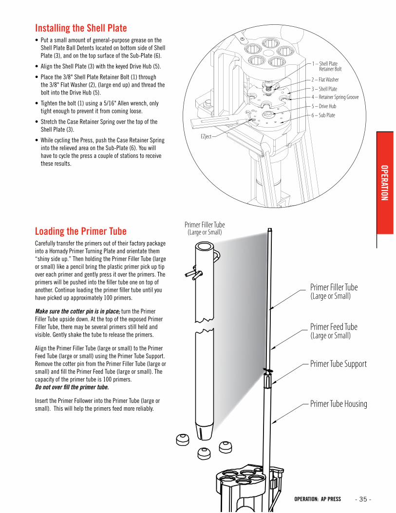
Installing the Shell Plate• Put a small amount of general-purpose grease on the
Shell Plate Ball Detents located on bottom side of Shell Plate (3), and on the top surface of the Sub-Plate (6).
• Align the Shell Plate (3) with the keyed Drive Hub (5).
• Place the 3/8" Shell Plate Retainer Bolt (1) through the 3/8" Flat Washer (2), (large end up) and thread the bolt into the Drive Hub (5).
• Tighten the bolt (1) using a 5/16" Allen wrench, only tight enough to prevent it from coming loose.
• Stretch the Case Retainer Spring over the top of the Shell Plate (3).
• While cycling the Press, push the Case Retainer Spring into the relieved area on the Sub-Plate (6). You will have to cycle the press a couple of stations to receive these results.
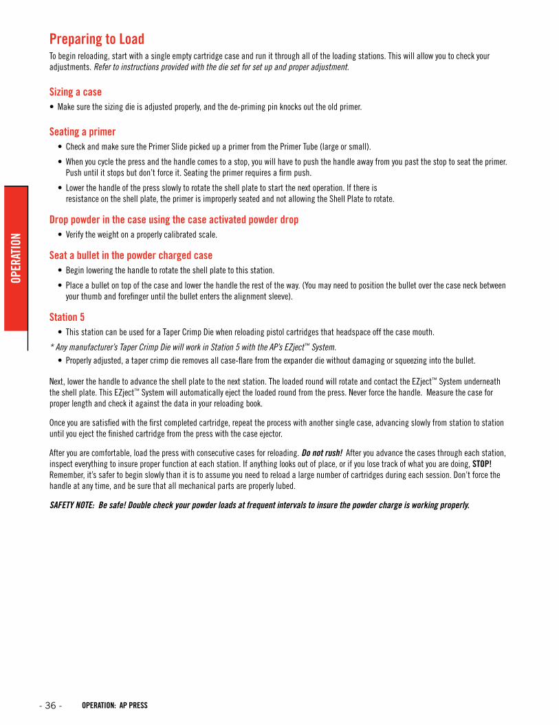
Loading the Primer TubeCarefully transfer the primers out of their factory package into a Hornady Primer Turning Plate and orientate them “shiny side up.” Then holding the Primer Filler Tube (large or small) like a pencil bring the plastic primer pick up tip over each primer and gently press it over the primers. The primers will be pushed into the filler tube one on top of another. Continue loading the primer filler tube until you have picked up approximately 100 primers.
Make sure the cotter pin is in place; turn the Primer Filler Tube upside down. At the top of the exposed Primer Filler Tube, there may be several primers still held and visible. Gently shake the tube to release the primers.
Align the Primer Filler Tube (large or small) to the Primer Feed Tube (large or small) using the Primer Tube Support. Remove the cotter pin from the Primer Filler Tube (large or small) and fill the Primer Feed Tube (large or small). The capacity of the primer tube is 100 primers. Do not over fill the primer tube.
Insert the Primer Follower into the Primer Tube (large or small). This will help the primers feed more reliably.
- 35 -OPERATION: AP PRESS
OPERATION
Preparing to LoadTo begin reloading, start with a single empty cartridge case and run it through all of the loading stations. This will allow you to check your adjustments. Refer to instructions provided with the die set for set up and proper adjustment.
Sizing a case• Make sure the sizing die is adjusted properly, and the de-priming pin knocks out the old primer.
Seating a primer• Check and make sure the Primer Slide picked up a primer from the Primer Tube (large or small).
• When you cycle the press and the handle comes to a stop, you will have to push the handle away from you past the stop to seat the primer. Push until it stops but don’t force it. Seating the primer requires a firm push.
• Lower the handle of the press slowly to rotate the shell plate to start the next operation. If there is resistance on the shell plate, the primer is improperly seated and not allowing the Shell Plate to rotate.
Drop powder in the case using the case activated powder drop• Verify the weight on a properly calibrated scale.
Seat a bullet in the powder charged case• Begin lowering the handle to rotate the shell plate to this station.
• Place a bullet on top of the case and lower the handle the rest of the way. (You may need to position the bullet over the case neck between your thumb and forefinger until the bullet enters the alignment sleeve).
Station 5• This station can be used for a Taper Crimp Die when reloading pistol cartridges that headspace off the case mouth.
* Any manufacturer’s Taper Crimp Die will work in Station 5 with the AP’s EZject™ System.• Properly adjusted, a taper crimp die removes all case-flare from the expander die without damaging or squeezing into the bullet.
Next, lower the handle to advance the shell plate to the next station. The loaded round will rotate and contact the EZject™ System underneath the shell plate. This EZject™ System will automatically eject the loaded round from the press. Never force the handle. Measure the case for proper length and check it against the data in your reloading book.
Once you are satisfied with the first completed cartridge, repeat the process with another single case, advancing slowly from station to station until you eject the finished cartridge from the press with the case ejector.
After you are comfortable, load the press with consecutive cases for reloading. Do not rush! After you advance the cases through each station, inspect everything to insure proper function at each station. If anything looks out of place, or if you lose track of what you are doing, STOP! Remember, it’s safer to begin slowly than it is to assume you need to reload a large number of cartridges during each session. Don’t force the handle at any time, and be sure that all mechanical parts are properly lubed.
SAFETY NOTE: Be safe! Double check your powder loads at frequent intervals to insure the powder charge is working properly.
- 36 - OPERATION: AP PRESS
OPER
ATIO
N
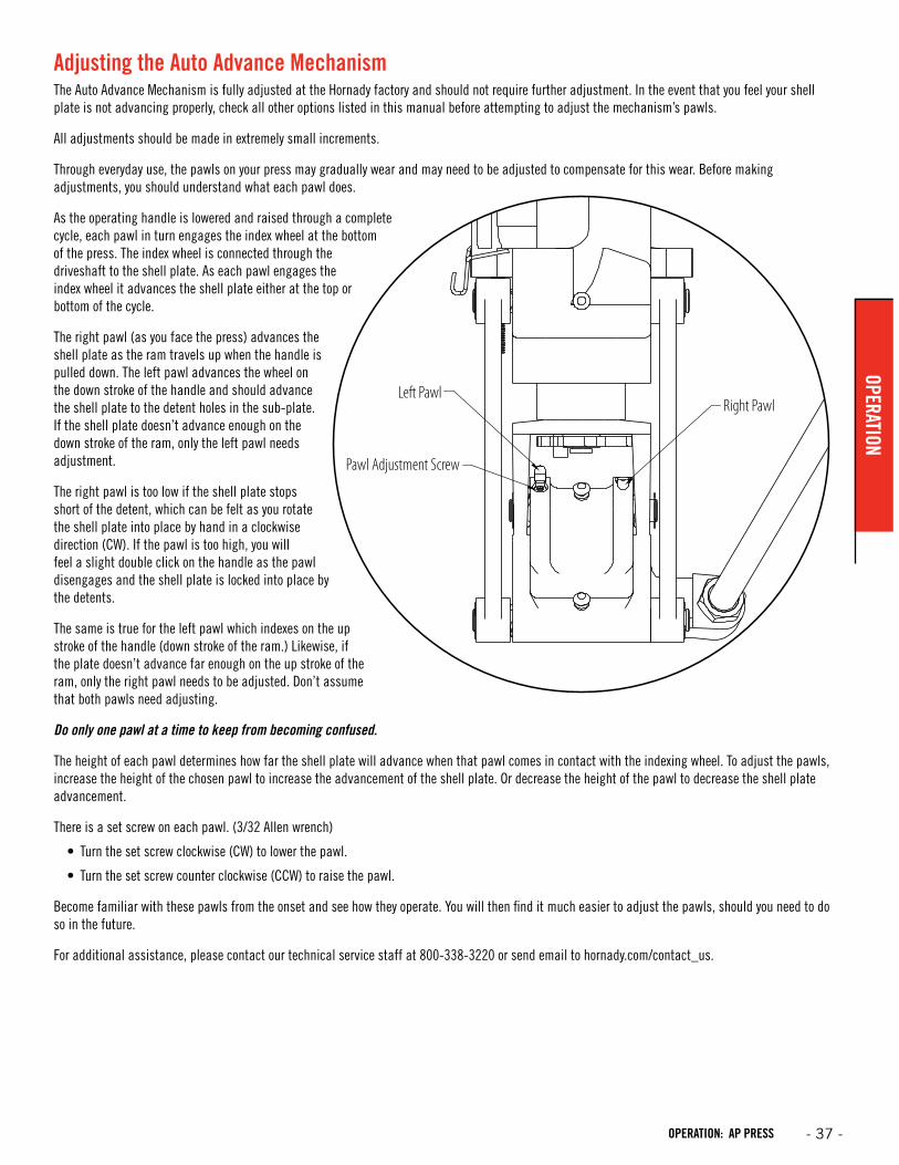
Adjusting the Auto Advance MechanismThe Auto Advance Mechanism is fully adjusted at the Hornady factory and should not require further adjustment. In the event that you feel your shell plate is not advancing properly, check all other options listed in this manual before attempting to adjust the mechanism’s pawls.
All adjustments should be made in extremely small increments.
Through everyday use, the pawls on your press may gradually wear and may need to be adjusted to compensate for this wear. Before making adjustments, you should understand what each pawl does.
As the operating handle is lowered and raised through a complete cycle, each pawl in turn engages the index wheel at the bottom of the press. The index wheel is connected through the driveshaft to the shell plate. As each pawl engages the index wheel it advances the shell plate either at the top or bottom of the cycle.
The right pawl (as you face the press) advances the shell plate as the ram travels up when the handle is pulled down. The left pawl advances the wheel on the down stroke of the handle and should advance the shell plate to the detent holes in the sub-plate. If the shell plate doesn’t advance enough on the down stroke of the ram, only the left pawl needs adjustment.
The right pawl is too low if the shell plate stops short of the detent, which can be felt as you rotate the shell plate into place by hand in a clockwise direction (CW). If the pawl is too high, you will feel a slight double click on the handle as the pawl disengages and the shell plate is locked into place by the detents.
The same is true for the left pawl which indexes on the up stroke of the handle (down stroke of the ram.) Likewise, if the plate doesn’t advance far enough on the up stroke of the ram, only the right pawl needs to be adjusted. Don’t assume that both pawls need adjusting.
Do only one pawl at a time to keep from becoming confused.
The height of each pawl determines how far the shell plate will advance when that pawl comes in contact with the indexing wheel. To adjust the pawls, increase the height of the chosen pawl to increase the advancement of the shell plate. Or decrease the height of the pawl to decrease the shell plate advancement.
There is a set screw on each pawl. (3/32 Allen wrench)
• Turn the set screw clockwise (CW) to lower the pawl.
• Turn the set screw counter clockwise (CCW) to raise the pawl.
Become familiar with these pawls from the onset and see how they operate. You will then find it much easier to adjust the pawls, should you need to do so in the future.
For additional assistance, please contact our technical service staff at 800-338-3220 or send email to hornady.com/contact_us.
Right PawlLeft Pawl
Pawl Adjustment Screw
- 37 -OPERATION: AP PRESS
OPERATION
Size and De-Prime DieEject
Ammo
FeedCase
LNL Powder Drop with
PTX
Powder Cop(optional)
Pistol Bullet Feeder
Die
Taper Crimp/ Seating Die
Typical Pistol Die Setup on the Hornady
Lock-N-Load Ammo Plant
Prime Case
Size and De-Prime DieEject
Ammo
FeedCase
LNL Powder Drop with
PTX
Seating Die
Pistol Bullet Feeder
Die
Taper CrimpDie
Alternate Pistol Die Setup on the Hornady
Lock-N-Load Ammo Plant
Prime Case
Size and De-Prime DieEject
Ammo
FeedCase
Lock-N-Load Powder Drop
Seating Die
PowderCop
(optional)
Open TypicalRifle Die Setup on the Hornady
Lock-N-Load Ammo Plant
FeedBullet
Prime Case
Die Setup Configurations
Determine the dies needed.The Hornady Lock-N-Load® AP™ Press is designed to use Hornady dies as well as most other dies with a 7/8"-14 threaded body. However, the characteristics of each die is different and will determine the setup and capabilities of the press. For example, using the Hornady Pistol Taper Crimp/Seating Die will free up a station on the press so that a Powder Cop Die may be used. Please see the various layout options below to help locate your dies on the press.
Die Mounting InstructionsFor initial die cleaning and individual die adjustment instructions, please refer to the instruction sheet that came with your die set.
Lock-N-Load® quick change bushing systemThe Lock-N-Load® system is based on the positive locking action of the bolt action rifle. Just like the bolt action rifle, the locking action is incredibly strong and simple.
Once the dies and the powder measure are adjusted for loading, these settings are locked in place by tightening the Lock Ring that is provided with all Hornady dies and powder measures.
How the Lock-N-Load® works:• Insert the Lock-N-Load® Bushing into the Press and turn it
clockwise to lock it in place.
• Adjust the die to the desired position and lock the setting in place with the die’s lock ring.
Once Lock-N-Load® Bushings are installed, Dies and Powder Drop can be removed from the press with a quick counterclockwise turn. Since the Lock-N-Load® Bushing is locked in place, the dies and the Powder Drop remain set exactly as you left them.
For added speed and convenience, Hornady® offers inexpensive Quick Change Powder Dies for use with the Case Activated Powder Drop.
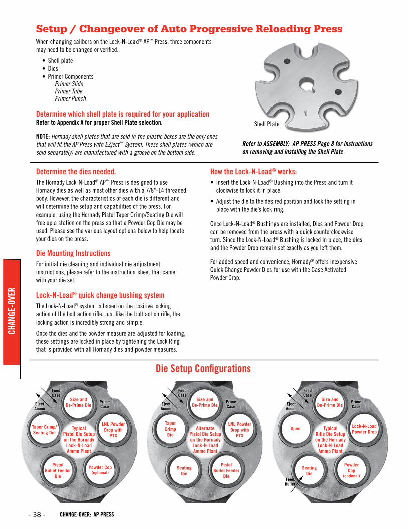
Shell Plate
Refer to ASSEMBLY: AP PRESS Page 8 for instructions on removing and installing the Shell Plate
When changing calibers on the Lock-N-Load® AP™ Press, three components may need to be changed or verified.
• Shell plate• Dies• Primer Components
Primer Slide Primer Tube Primer Punch
Determine which shell plate is required for your applicationRefer to Appendix A for proper Shell Plate selection.
NOTE: Hornady shell plates that are sold in the plastic boxes are the only ones that will fit the AP Press with EZject™ System. These shell plates (which are sold separately) are manufactured with a groove on the bottom side.
Setup / Changeover of Auto Progressive Reloading Press
- 38 - CHANGE-OVER: AP PRESS
CHAN
GE-O
VER

Changing Primer ComponentsWhen changing from a large primer to a small primer (or vice versa), you need to change the Primer Feed Tube Primer Slide and Punch Assembly.
If there are primers in the Primer Feed Tube, you will need to empty it before changing the tubes. If the Primer Feed Tube is already empty, skip to next step.
Remove the Cap Screw, cup your hand under the Primer Tube and rotate the Primer Feed Body Assembly clockwise to catch the primers. After the tube is empty, rotate the body back in place and re-install the mounting screw.
Disconnect the Spring from the roller pin and remove the Primer Slide. Remove the Primer Tube Support and the Primer Feed Tube.
Fill the primer tube as described in the Operations Section.
The Primer Seater Punches are installed from the bottom side of the Sub-Plate. Raise the Ram to the top of the stroke. Use a wrench to loosen the Primer Seater Punch and unscrew it from the Sub-Plate. When installing a new Primer Seater Punch, tighten it snug with a wrench. Do not over tighten the Primer Punch.
3
4
2
11
2
3
4
Primer Feed Tube
Primer Seater Punch
Primer Slide
Primer Slide
Spring
Punch Assembly
- 39 -CHANGE-OVER: AP PRESS
CHANGE-OVER

When changing cartridges, three components on the Powder Measure may need to be changed or verified.
• Powder type in the hopper.• Metering Insert and/or Metering Rotor• Powder Sleeve or PTX Expander
Emptying Powder in HopperNOTE: The Lock-N-Load® Powder Measure should be emptied of all powder prior to storage. Prolonged exposure to powder may cause the plastic tube to become cloudy, discolored, or even brittle.
To remove powder from the Lock-N-Load® Powder Measure hopper, either use the Hornady® Powder Measure Drain Insert (sold separately 050125) or remove the entire Powder Measure assembly from the press, remove the cap, and pour back into the original powder container. Cycle the rotor a few times while holding the powder measure over a container to remove the powder from the rotor. Finally remove the Metering Insert to inspect for any residual powder.
Changing Meter Insert and RotorThe Lock-N-Load® Powder Measure ships with two sets of Rotors and Standard Inserts. The Pistol Rotor and Insert are for powder charges from approximately 0.5 grains to 17 grains. The Rifle Rotor and Standard Insert are for powder charges from approximately 15 grains to 100 grains.
Additional inserts are available and sold separately to make change overs and reloading quicker and easier by storing the Metering Insert with the die set so minimal adjustments are needed when changing cartridges.
To change the insert, press the button on the side of the rotor. While pressing the button, pull and wiggle the Metering Insert out of the Rotor body. To install the new Metering Insert, press and hold the button on the side of the rotor, align the flats on the Metering Insert with the body of the Powder Measure, and press the insert into the Rotor. Verify the insert is fully inserted by firmly pulling on the Metering Insert.
NOTE: If there is powder in the hopper and the Metering Insert is on the bottom of the stroke, removing the Metering Insert will cause powder to empty out of the Powder Measure hopper and onto your work area.
If you are changing from a pistol cartridge to a rifle cartridge (or vice versa), you will need to change the Rotor in the Powder Measure.
To remove the Rotor, first remove the Metering Insert following the Instructions above. Next, remove the two screws from the side of the Rotor. Slide the Rotor out of the Powder Measure body.
Insert the correct Rotor by gently sliding it into the Powder Measure body. The manufacturing tolerances are very tight on the both the rotor and Powder Measure body, so caution should be used to prevent causing damage to the either component. Insert the correct Metering Insert and reattach the linkage with the two screws.
Setup / Changeover of Powder Measure
3
2
1
1
2
3
Metering Insert
Rotor
- 40 - CHANGE-OVER: POWDER MEASURE
CHAN
GE-O
VER
Powder SleevesItem No. 392700* 392701* 392702* 392703
Caliber Universal Pistol Powder Sleeve #1 Powder Sleeve #2 Powder Sleeve 17 Cal. Powder Sleeve
Description Most Pistol Cases** 7mm to 45 Cal. Rifle Cases
20 to 270 Cal. Rifle Cases 17 Cal. Rifle Cases
* Included with the Lock-N-Load AP™**Does not flare case
PTX Expanders (optional)
Item No. 290030 290031 290032 290033
Caliber .355 PTX .357 PTX .400 PTX .430 PTX
Description 9mm Pistol Cases 38 Cal. Pistol Cases 10mm Pistol Cases 44 Cal. Pistol Cases
Item No. 290034 290036 290037 290038
Caliber .451 PTX .452 PTX .475 PTX 500 PTX
Description 45 Cal. Pistol Cases 45 Cal. Pistol Cases 475 Cal. Pistol Cases 50 Cal. Pistol Cases
(PTX = Powder Thru Expander)
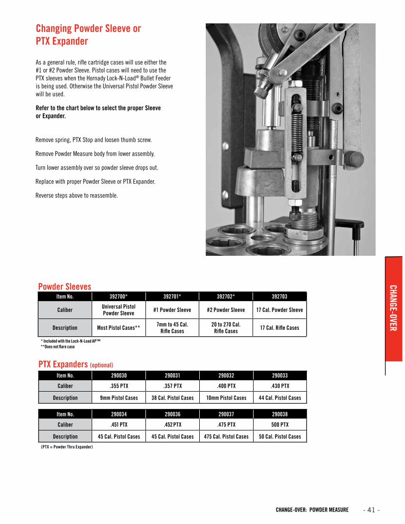
Changing Powder Sleeve or PTX Expander
As a general rule, rifle cartridge cases will use either the #1 or #2 Powder Sleeve. Pistol cases will need to use the PTX sleeves when the Hornady Lock-N-Load® Bullet Feeder is being used. Otherwise the Universal Pistol Powder Sleeve will be used.
Refer to the chart below to select the proper Sleeve or Expander.
Remove spring, PTX Stop and loosen thumb screw.
Remove Powder Measure body from lower assembly.
Turn lower assembly over so powder sleeve drops out.
Replace with proper Powder Sleeve or PTX Expander.
Reverse steps above to reassemble.
- 41 -CHANGE-OVER: POWDER MEASURE
CHANGE-OVER
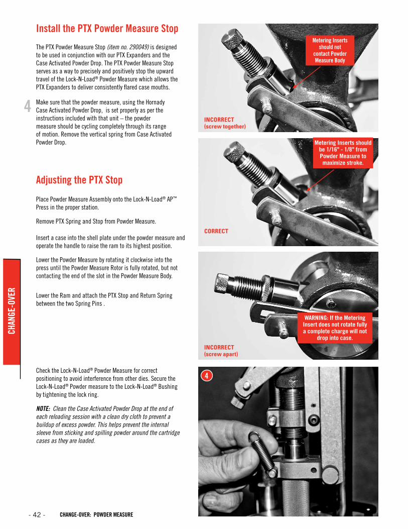
INCORRECT(screw together)
INCORRECT(screw apart)
CORRECT
Metering Inserts should not
contact Powder Measure Body
Metering Inserts should be 1/16" - 1/8" from Powder Measure to maximize stroke.
WARNING: If the Metering Insert does not rotate fully a complete charge will not
drop into case.
4
Insert a case into the shell plate under the powder measure and operate the handle to raise the ram to its highest position.
Lower the Powder Measure by rotating it clockwise into the press until the Powder Measure Rotor is fully rotated, but not contacting the end of the slot in the Powder Measure Body.
Lower the Ram and attach the PTX Stop and Return Spring between the two Spring Pins .
Adjusting the PTX Stop
Place Powder Measure Assembly onto the Lock-N-Load® AP™ Press in the proper station.
Remove PTX Spring and Stop from Powder Measure.
Check the Lock-N-Load® Powder Measure for correct positioning to avoid interference from other dies. Secure the Lock-N-Load® Powder measure to the Lock-N-Load® Bushing by tightening the lock ring.
NOTE: Clean the Case Activated Powder Drop at the end of each reloading session with a clean dry cloth to prevent a buildup of excess powder. This helps prevent the internal sleeve from sticking and spilling powder around the cartridge cases as they are loaded.
Install the PTX Powder Measure Stop
The PTX Powder Measure Stop (item no. 290049) is designed to be used in conjunction with our PTX Expanders and the Case Activated Powder Drop. The PTX Powder Measure Stop serves as a way to precisely and positively stop the upward travel of the Lock-N-Load® Powder Measure which allows the PTX Expanders to deliver consistently flared case mouths.
4 Make sure that the powder measure, using the Hornady Case Activated Powder Drop, is set properly as per the instructions included with that unit – the powder measure should be cycling completely through its range of motion. Remove the vertical spring from Case Activated Powder Drop.
- 42 - CHANGE-OVER: POWDER MEASURE
CHAN
GE-O
VER
6
5
6
5
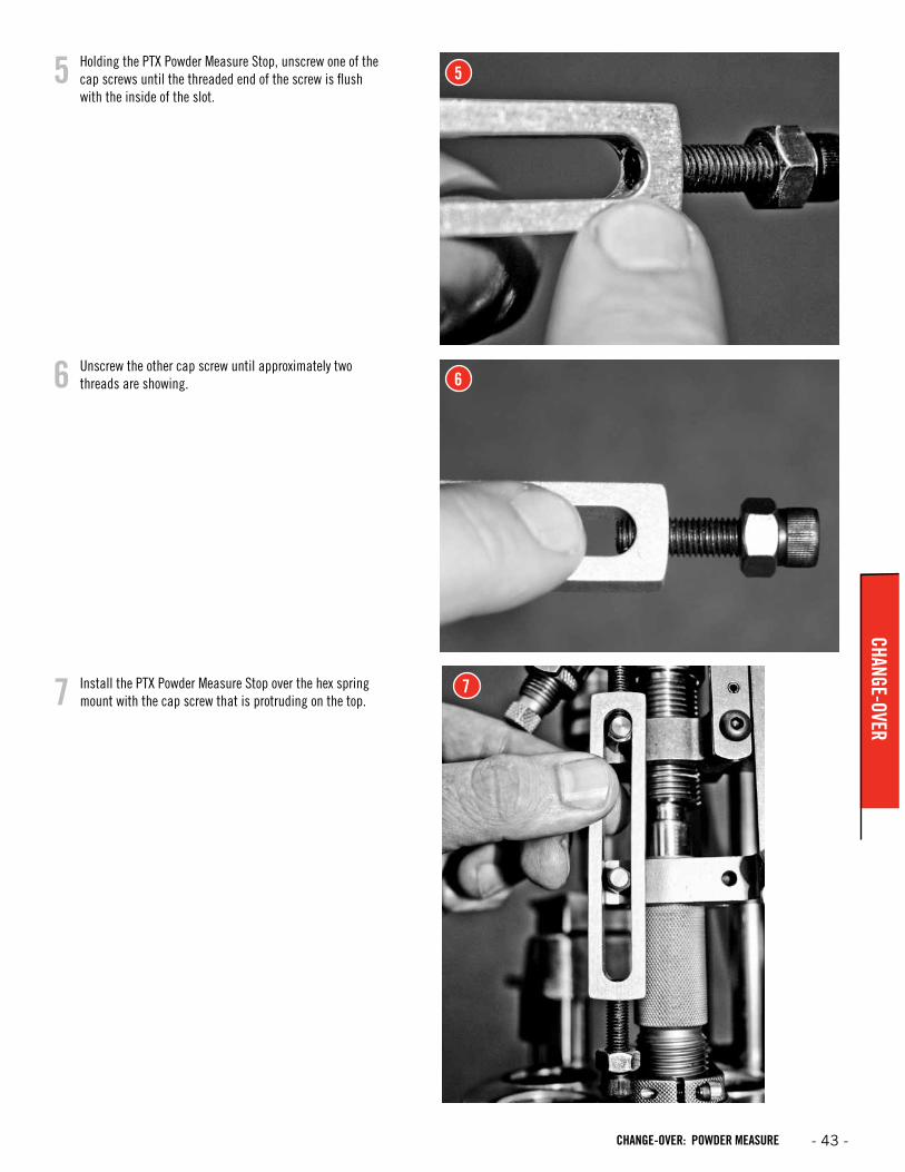
Unscrew the other cap screw until approximately two threads are showing.
Holding the PTX Powder Measure Stop, unscrew one of the cap screws until the threaded end of the screw is flush with the inside of the slot.
Install the PTX Powder Measure Stop over the hex spring mount with the cap screw that is protruding on the top.7 7
- 43 -CHANGE-OVER: POWDER MEASURE
CHANGE-OVER
8
9
10
8
9
10
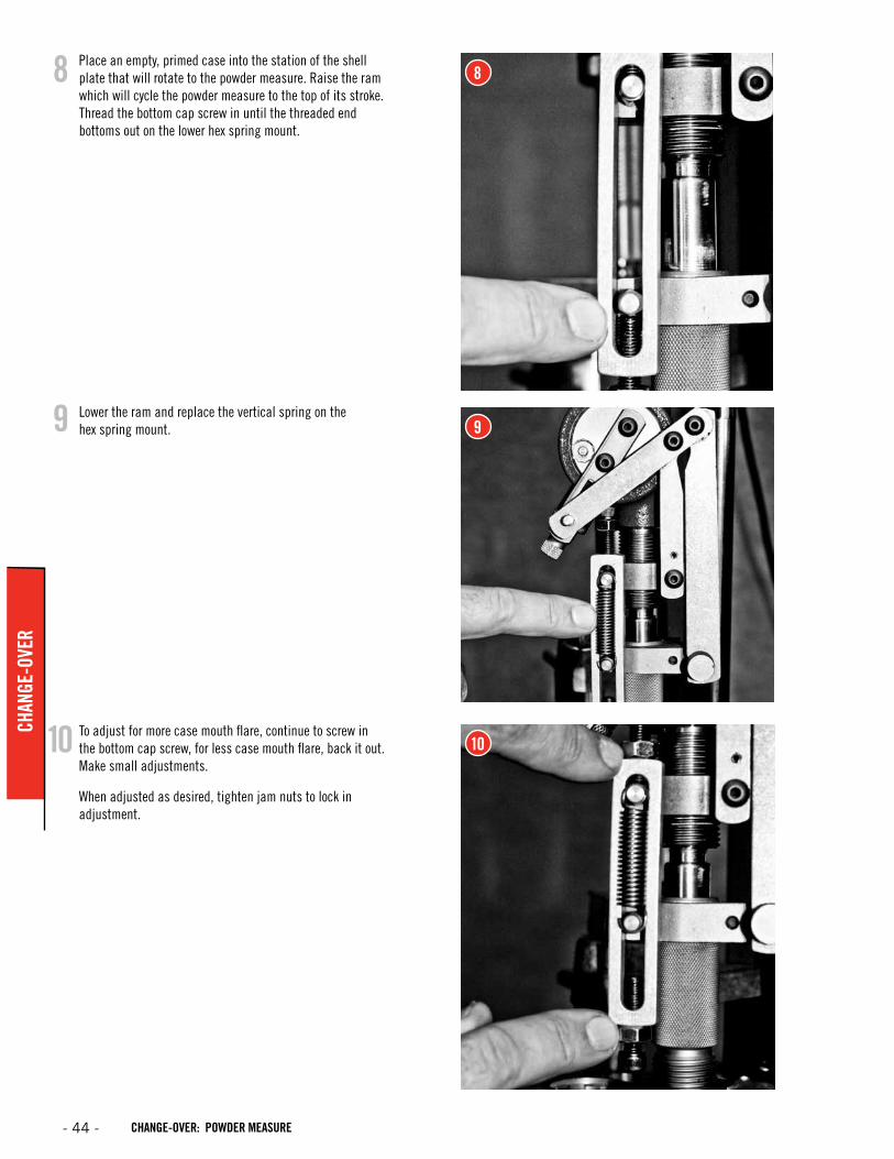
Place an empty, primed case into the station of the shell plate that will rotate to the powder measure. Raise the ram which will cycle the powder measure to the top of its stroke. Thread the bottom cap screw in until the threaded end bottoms out on the lower hex spring mount.
Lower the ram and replace the vertical spring on the hex spring mount.
To adjust for more case mouth flare, continue to screw in the bottom cap screw, for less case mouth flare, back it out. Make small adjustments.
When adjusted as desired, tighten jam nuts to lock in adjustment.
- 44 - CHANGE-OVER: POWDER MEASURE
CHAN
GE-O
VER
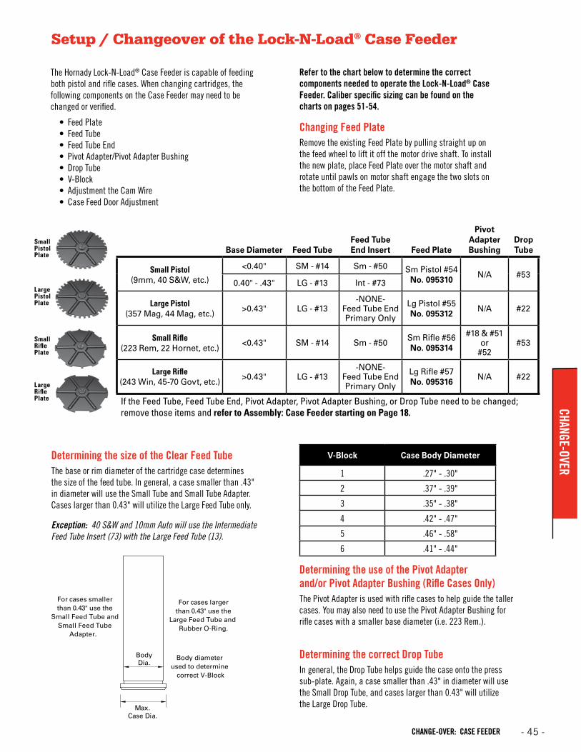
Refer to the chart below to determine the correct components needed to operate the Lock-N-Load® Case Feeder. Caliber specific sizing can be found on the charts on pages 51-54.
Setup / Changeover of the Lock-N-Load® Case Feeder
Changing Feed PlateRemove the existing Feed Plate by pulling straight up on the feed wheel to lift it off the motor drive shaft. To install the new plate, place Feed Plate over the motor shaft and rotate until pawls on motor shaft engage the two slots on the bottom of the Feed Plate.
The Hornady Lock-N-Load® Case Feeder is capable of feeding both pistol and rifle cases. When changing cartridges, the following components on the Case Feeder may need to be changed or verified.
• Feed Plate• Feed Tube• Feed Tube End• Pivot Adapter/Pivot Adapter Bushing• Drop Tube• V-Block• Adjustment the Cam Wire• Case Feed Door Adjustment
Small Rifle Plate
Large Rifle Plate
Large Pistol Plate
Small Pistol Plate
Base Diameter Feed TubeFeed Tube End Insert Feed Plate
Pivot Adapter Bushing
Drop Tube
Small Pistol(9mm, 40 S&W, etc.)
<0.40" SM - #14 Sm - #50 Sm Pistol #54No. 095310
N/A #530.40" - .43" LG - #13 Int - #73
Large Pistol(357 Mag, 44 Mag, etc.)
>0.43" LG - #13-NONE-
Feed Tube End Primary Only
Lg Pistol #55No. 095312
N/A #22
Small Rifle(223 Rem, 22 Hornet, etc.)
<0.43" SM - #14 Sm - #50Sm Rifle #56No. 095314
#18 & #51or
#52#53
Large Rifle(243 Win, 45-70 Govt, etc.)
>0.43" LG - #13-NONE-
Feed Tube End Primary Only
Lg Rifle #57No. 095316
N/A #22
If the Feed Tube, Feed Tube End, Pivot Adapter, Pivot Adapter Bushing, or Drop Tube need to be changed; remove those items and refer to Assembly: Case Feeder starting on Page 18.
V-Block Case Body Diameter
1 .27" - .30"
2 .37" - .39"
3 .35" - .38"
4 .42" - .47"
5 .46" - .58"
6 .41" - .44"
Max.
Body Dia.
Case Dia.
For cases smallerthan 0.43" use the
Small Feed Tube andSmall Feed Tube
Adapter.
For cases largerthan 0.43" use the
Large Feed Tube and Rubber O-Ring.
Body diameter used to determine
correct V-Block
Determining the size of the Clear Feed TubeThe base or rim diameter of the cartridge case determines the size of the feed tube. In general, a case smaller than .43" in diameter will use the Small Tube and Small Tube Adapter. Cases larger than 0.43" will utilize the Large Feed Tube only.
Exception: 40 S&W and 10mm Auto will use the Intermediate Feed Tube Insert (73) with the Large Feed Tube (13).
Determining the use of the Pivot Adapter and/or Pivot Adapter Bushing (Rifle Cases Only)The Pivot Adapter is used with rifle cases to help guide the taller cases. You may also need to use the Pivot Adapter Bushing for rifle cases with a smaller base diameter (i.e. 223 Rem.).
Determining the correct Drop TubeIn general, the Drop Tube helps guide the case onto the press sub-plate. Again, a case smaller than .43" in diameter will use the Small Drop Tube, and cases larger than 0.43" will utilize the Large Drop Tube.
- 45 -CHANGE-OVER: CASE FEEDER
CHANGE-OVER
Cap Screw
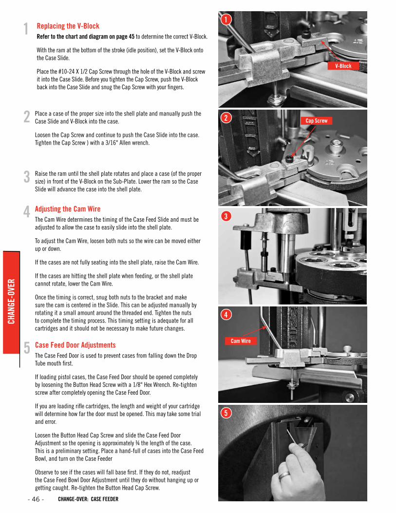
Adjusting the Cam WireThe Cam Wire determines the timing of the Case Feed Slide and must be adjusted to allow the case to easily slide into the shell plate.
To adjust the Cam Wire, loosen both nuts so the wire can be moved either up or down.
If the cases are not fully seating into the shell plate, raise the Cam Wire.
If the cases are hitting the shell plate when feeding, or the shell plate cannot rotate, lower the Cam Wire.
Once the timing is correct, snug both nuts to the bracket and make sure the cam is centered in the Slide. This can be adjusted manually by rotating it a small amount around the threaded end. Tighten the nuts to complete the timing process. This timing setting is adequate for all cartridges and it should not be necessary to make future changes.
Raise the ram until the shell plate rotates and place a case (of the proper size) in front of the V-Block on the Sub-Plate. Lower the ram so the Case Slide will advance the case into the shell plate.
Place a case of the proper size into the shell plate and manually push the Case Slide and V-Block into the case.
Loosen the Cap Screw and continue to push the Case Slide into the case. Tighten the Cap Screw ) with a 3/16" Allen wrench.
2
3
4
2
3
4
Cam WireCase Feed Door AdjustmentsThe Case Feed Door is used to prevent cases from falling down the Drop Tube mouth first.
If loading pistol cases, the Case Feed Door should be opened completely by loosening the Button Head Screw with a 1/8" Hex Wrench. Re-tighten screw after completely opening the Case Feed Door.
If you are loading rifle cartridges, the length and weight of your cartridge will determine how far the door must be opened. This may take some trial and error.
Loosen the Button Head Cap Screw and slide the Case Feed Door Adjustment so the opening is approximately ¾ the length of the case. This is a preliminary setting. Place a hand-full of cases into the Case Feed Bowl, and turn on the Case Feeder
Observe to see if the cases will fall base first. If they do not, readjust the Case Feed Bowl Door Adjustment until they do without hanging up or getting caught. Re-tighten the Button Head Cap Screw.
5
5
V-Block
Replacing the V-BlockRefer to the chart and diagram on page 45 to determine the correct V-Block.
With the ram at the bottom of the stroke (idle position), set the V-Block onto the Case Slide.
Place the #10-24 X 1/2 Cap Screw through the hole of the V-Block and screw it into the Case Slide. Before you tighten the Cap Screw, push the V-Block back into the Case Slide and snug the Cap Screw with your fingers.
11
- 46 - CHANGE-OVER: CASE FEEDER
CHAN
GE-O
VER
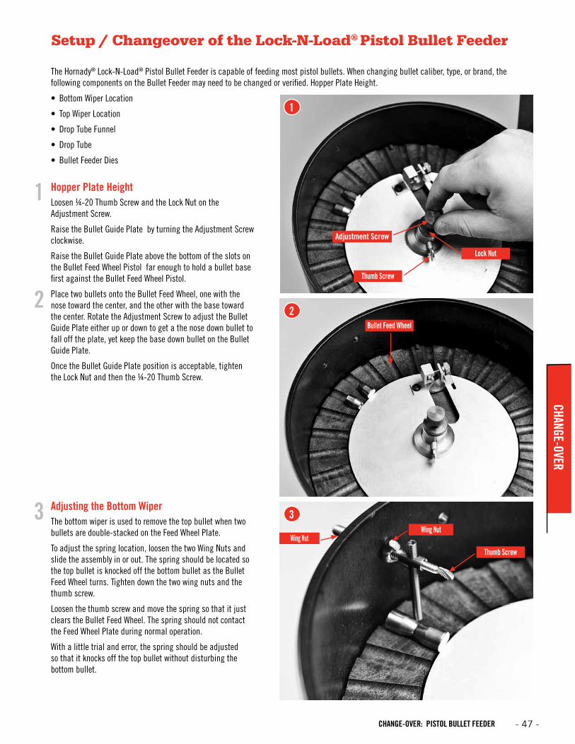
Setup / Changeover of the Lock-N-Load® Pistol Bullet Feeder
The Hornady® Lock-N-Load® Pistol Bullet Feeder is capable of feeding most pistol bullets. When changing bullet caliber, type, or brand, the following components on the Bullet Feeder may need to be changed or verified. Hopper Plate Height.
• Bottom Wiper Location
• Top Wiper Location
• Drop Tube Funnel
• Drop Tube
• Bullet Feeder Dies
Hopper Plate Height Loosen ¼-20 Thumb Screw and the Lock Nut on the Adjustment Screw.
Raise the Bullet Guide Plate by turning the Adjustment Screw clockwise.
Raise the Bullet Guide Plate above the bottom of the slots on the Bullet Feed Wheel Pistol far enough to hold a bullet base first against the Bullet Feed Wheel Pistol.
Place two bullets onto the Bullet Feed Wheel, one with the nose toward the center, and the other with the base toward the center. Rotate the Adjustment Screw to adjust the Bullet Guide Plate either up or down to get a the nose down bullet to fall off the plate, yet keep the base down bullet on the Bullet Guide Plate.
Once the Bullet Guide Plate position is acceptable, tighten the Lock Nut and then the ¼-20 Thumb Screw.
Adjusting the Bottom WiperThe bottom wiper is used to remove the top bullet when two bullets are double-stacked on the Feed Wheel Plate.
To adjust the spring location, loosen the two Wing Nuts and slide the assembly in or out. The spring should be located so the top bullet is knocked off the bottom bullet as the Bullet Feed Wheel turns. Tighten down the two wing nuts and the thumb screw.
Loosen the thumb screw and move the spring so that it just clears the Bullet Feed Wheel. The spring should not contact the Feed Wheel Plate during normal operation.
With a little trial and error, the spring should be adjusted so that it knocks off the top bullet without disturbing the bottom bullet.
1
2
3
1
2
3
Adjustment Screw
Lock Nut
Wing Nut
Thumb Screw
Thumb Screw
Bullet Feed Wheel
Wing Nut
- 47 -CHANGE-OVER: PISTOL BULLET FEEDER
CHANGE-OVER
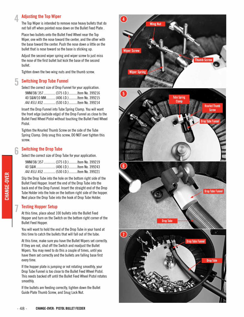
Adjusting the Top WiperThe Top Wiper is intended to remove nose heavy bullets that do not fall off when pointed nose down on the Bullet Feed Plate .
Place two bullets onto the Bullet Feed Wheel near the Top Wiper, one with the nose toward the center, and the other with the base toward the center. Push the nose down a little on the bullet that is nose toward so the base is sticking up.
Adjust the second wiper spring and wiper screw to just miss the nose of the first bullet but kick the base of the second bullet.
Tighten down the two wing nuts and the thumb screw.
Switching Drop Tube FunnelSelect the correct size of Drop Funnel for your application. 9MM/38/.357 .............. (375 I.D.) ..........Item No. 399216 40 S&W/10 MM ........... (406 I.D.) ..........Item No. 399215 .44/.451/.452 .............. (530 I.D.) ..........Item No. 399214
Insert the Drop Funnel into Tube Spring Clamp. You will want the front edge (outside edge) of the Drop Funnel as close to the Bullet Feed Wheel Pistol without touching the Bullet Feed Wheel Pistol.
Tighten the Knurled Thumb Screw on the side of the Tube Spring Clamp. Only snug this screw, DO NOT over tighten this screw.
Switching the Drop TubeSelect the correct size of Drop Tube for your application.
9MM/38/.357 .............. (375 I.D.) ..........Item No. 399219 40 S&W ....................... (406 I.D.) ..........Item No. 399243 .44/.451/.452 .............. (530 I.D.) ..........Item No. 399221
Slip the Drop Tube into the hole on the bottom right side of the Bullet Feed Hopper. Insert the end of the Drop Tube into the back end of the Drop Funnel. Insert the straight end of the Drop Tube Holder into the hole on the bottom right side of the hopper. Next place the Drop Tube into the hook of Drop Tube Holder.
Testing Hopper SetupAt this time, place about 100 bullets into the Bullet Feed Hopper and turn on the Switch on the bottom right corner of the Bullet Feed Hopper.
You will want to hold the end of the Drop Tube in your hand at this time to catch the bullets that will fall out of the tube.
At this time, make sure you have the Bullet Wipers set correctly. If they are not, shut off the Switch and readjust the Bullet Wipers. You may need to do this a couple of times, until you have them set correctly and the bullets are falling base first every time.
If the hopper plate is jumping or not rotating smoothly, your Drop Tube Funnel is too close to the Bullet Feed Wheel Pistol. This needs backed off until the Bullet Feed Wheel Pistol rotates smoothly.
If the bullets are feeding correctly, tighten down the Bullet Guide Plate Thumb Screw, and Snug Lock Nut.
4
5
6
7
4
5
6
7
Wiper Spring
Wiper Screw
Wing Nut
Drop Tube
Drop Tube
Drop Tube Funnel
Drop Tube Funnel
Drop Tube Funnel
Knurled Thumb Screw
Tube Spring Clamp
Thumb Screw
- 48 - CHANGE-OVER: PISTOL BULLET FEEDER
CHAN
GE-O
VER
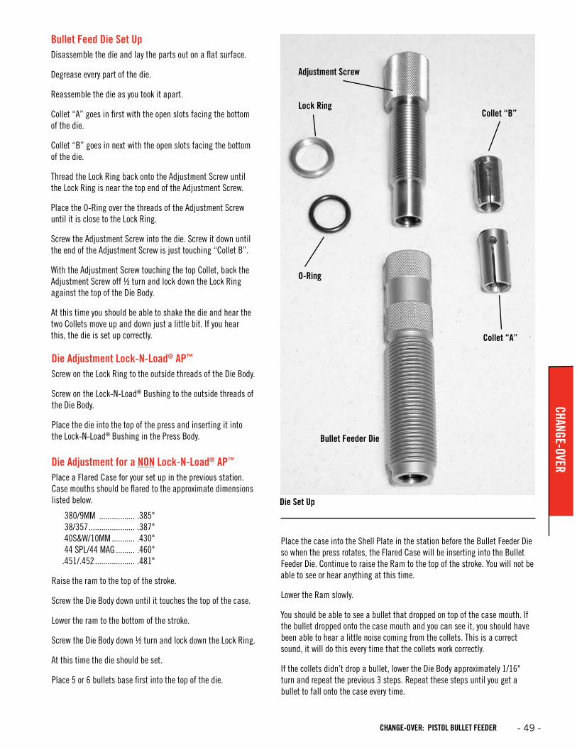
Bullet Feed Die Set UpDisassemble the die and lay the parts out on a flat surface.
Degrease every part of the die.
Reassemble the die as you took it apart.
Collet “A” goes in first with the open slots facing the bottom of the die.
Collet “B” goes in next with the open slots facing the bottom of the die.
Thread the Lock Ring back onto the Adjustment Screw until the Lock Ring is near the top end of the Adjustment Screw.
Place the O-Ring over the threads of the Adjustment Screw until it is close to the Lock Ring.
Screw the Adjustment Screw into the die. Screw it down until the end of the Adjustment Screw is just touching “Collet B”.
With the Adjustment Screw touching the top Collet, back the Adjustment Screw off ½ turn and lock down the Lock Ring against the top of the Die Body.
At this time you should be able to shake the die and hear the two Collets move up and down just a little bit. If you hear this, the die is set up correctly.
Die Adjustment Lock-N-Load® AP™
Screw on the Lock Ring to the outside threads of the Die Body.
Screw on the Lock-N-Load® Bushing to the outside threads of the Die Body.
Place the die into the top of the press and inserting it into the Lock-N-Load® Bushing in the Press Body.
Die Adjustment for a NON Lock-N-Load® AP™
Place a Flared Case for your set up in the previous station. Case mouths should be flared to the approximate dimensions listed below.
380/9MM ................. .385"38/357 ...................... .387"40S&W/10MM ........... .430"44 SPL/44 MAG ......... .460"
.451/.452 ................... .481"
Raise the ram to the top of the stroke.
Screw the Die Body down until it touches the top of the case.
Lower the ram to the bottom of the stroke.
Screw the Die Body down ½ turn and lock down the Lock Ring.
At this time the die should be set.
Place 5 or 6 bullets base first into the top of the die.
Place the case into the Shell Plate in the station before the Bullet Feeder Die so when the press rotates, the Flared Case will be inserting into the Bullet Feeder Die. Continue to raise the Ram to the top of the stroke. You will not be able to see or hear anything at this time.
Lower the Ram slowly.
You should be able to see a bullet that dropped on top of the case mouth. If the bullet dropped onto the case mouth and you can see it, you should have been able to hear a little noise coming from the collets. This is a correct sound, it will do this every time that the collets work correctly.
If the collets didn’t drop a bullet, lower the Die Body approximately 1/16" turn and repeat the previous 3 steps. Repeat these steps until you get a bullet to fall onto the case every time.
Adjustment Screw
Lock RingCollet “B”
Collet “A”
Bullet Feeder Die
O-Ring
Die Set Up
- 49 -CHANGE-OVER: PISTOL BULLET FEEDER
CHANGE-OVER
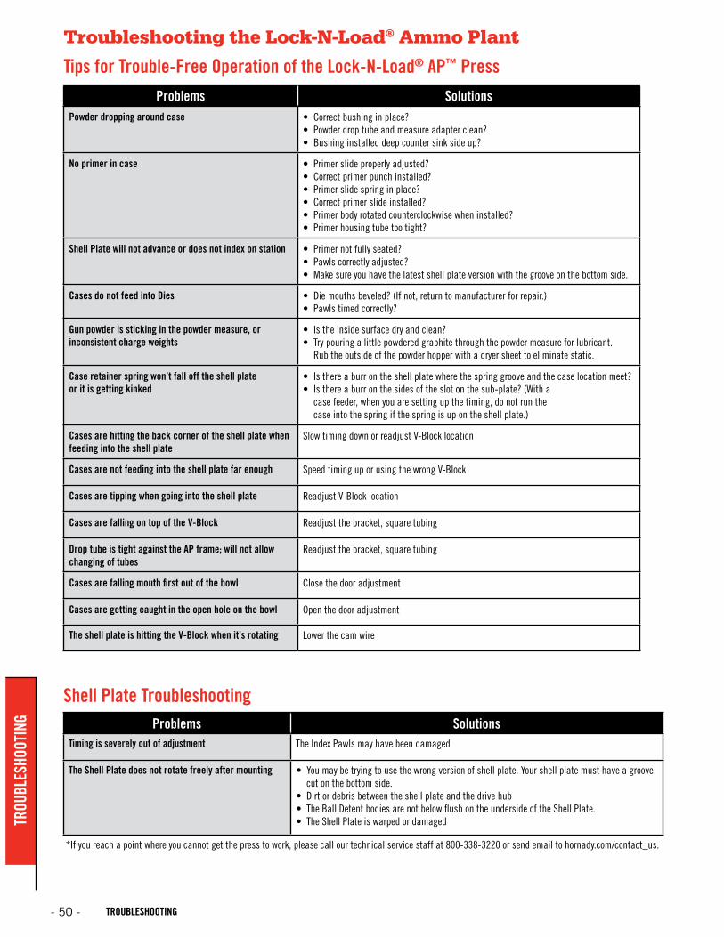
Troubleshooting the Lock-N-Load® Ammo Plant
Tips for Trouble-Free Operation of the Lock-N-Load® AP™ PressProblems Solutions
Powder dropping around case • Correct bushing in place? • Powder drop tube and measure adapter clean? • Bushing installed deep counter sink side up?
No primer in case • Primer slide properly adjusted? • Correct primer punch installed? • Primer slide spring in place? • Correct primer slide installed? • Primer body rotated counterclockwise when installed?• Primer housing tube too tight?
Shell Plate will not advance or does not index on station • Primer not fully seated? • Pawls correctly adjusted?• Make sure you have the latest shell plate version with the groove on the bottom side.
Cases do not feed into Dies • Die mouths beveled? (If not, return to manufacturer for repair.) • Pawls timed correctly?
Gun powder is sticking in the powder measure, or inconsistent charge weights
• Is the inside surface dry and clean?• Try pouring a little powdered graphite through the powder measure for lubricant.
Rub the outside of the powder hopper with a dryer sheet to eliminate static.
Case retainer spring won’t fall off the shell plate or it is getting kinked
• Is there a burr on the shell plate where the spring groove and the case location meet? • Is there a burr on the sides of the slot on the sub-plate? (With a
case feeder, when you are setting up the timing, do not run the case into the spring if the spring is up on the shell plate.)
Cases are hitting the back corner of the shell plate when feeding into the shell plate
Slow timing down or readjust V-Block location
Cases are not feeding into the shell plate far enough Speed timing up or using the wrong V-Block
Cases are tipping when going into the shell plate Readjust V-Block location
Cases are falling on top of the V-Block Readjust the bracket, square tubing
Drop tube is tight against the AP frame; will not allow changing of tubes
Readjust the bracket, square tubing
Cases are falling mouth first out of the bowl Close the door adjustment
Cases are getting caught in the open hole on the bowl Open the door adjustment
The shell plate is hitting the V-Block when it’s rotating Lower the cam wire
Shell Plate TroubleshootingProblems Solutions
Timing is severely out of adjustment The Index Pawls may have been damaged
The Shell Plate does not rotate freely after mounting • You may be trying to use the wrong version of shell plate. Your shell plate must have a groove cut on the bottom side.
• Dirt or debris between the shell plate and the drive hub• The Ball Detent bodies are not below flush on the underside of the Shell Plate.• The Shell Plate is warped or damaged
*If you reach a point where you cannot get the press to work, please call our technical service staff at 800-338-3220 or send email to hornady.com/contact_us.
- 50 - TROUBLESHOOTING
TROU
BLES
HOOT
ING

APPENDIX AAPPENDIX A
- 51 -
RIFLE DIES & RELOADING ESSENTIALS (Reference Chart)
Rifle Cartridge
Bulle
t Dia
met
er
(inch
es)
Die
Set
Die
Serie
sFu
ll-Le
ngth
Si
ze D
ie
Seat
ing
Die
Expa
nder
Die
Tape
r Crim
p
Die
Only
Nec
k Si
ze D
ie
Shel
l Hol
der
# / I
tem
No.
Shel
l Pla
te
# / I
tem
No.
Case
Fe
eder
Pla
te
Size
/ Ite
m N
o.
Bulle
t Fe
eder
Die
Trim
mer
Pilo
t #
/ Ite
m N
o.
Prim
er P
unch
Bulle
t Pu
ller C
olle
t #
/ Ite
m N
o.
Mod
ified
Cas
e
BLANK CART 22-45 CAL — 544591 IV — — — — — — / — — / — — / — — — / — — — / — —17 HORNET .172 546118 I 046202 044101 — — — #3 / 390543 #3 / 392603 Sm Rfl / 095314 — * / 390942 Small #1 / 392154 A17H17 REM FIREBALL .172 546117 I 046200 044101 — — — #16 / 390556 #16 / 392616 Sm Rfl / 095314 — * / 390942 Small #1 / 392154 B17R17 REM .172 546200 III 046201 044101 — — — #16 / 390556 #16 / 392616 Sm Rfl / 095314 — * / 390942 Small #1 / 392154 A1717-222 .172 546202 IV — — — — — #16 / 390556 #16 / 392616 Sm Rfl / 095314 — * / 390942 Small #1 / 392154 —17-223 .172 546204 IV — — — — — #16 / 390556 #16 / 392616 Sm Rfl / 095314 — * / 390942 Small #1 / 392154 —20 VT .204 546205 III 046206 044139 — — 046038 #16 / 390556 #16 / 392616 Sm Rfl / 095314 — #22 / 390940 Small #14 / 392167 —20 TACTICAL .204 546209 III 046208 044139 — — 046038 #16 / 390556 #16 / 392616 Sm Rfl / 095314 — #22 / 390940 Small #14 / 392167 —204 RUGER .204 546201 I 046590 044139 — — 046038 #16 / 390556 #16 / 392616 Sm Rfl / 095314 — #22 / 390940 Small #14 / 392167 B20422 HORNET .224 546212 I 046213 044206 — — 046066 #3 / 390543 #3 / 392603 Sm Rfl / 095314 — #1 / 390943 Small #2 / 392155 —22 K-HORNET .224 546214 IV — — — — 046066 #3 / 390543 #3 / 392603 Sm Rfl / 095314 — #1 / 390943 Small #2 / 392155 —5.7X28 FN .224 546203 III 046212 044136 — — — #37 / 390577 — / — Sm Rfl / 095314 — #1 / 390943 Small #2 / 392155 —218 BEE .224 546206 IV — — — — 046066 #7 / 390547 #7 / 392607 Sm Rfl / 095314 — #1 / 390943 Small #2 / 392155 A218221 REM FIREBALL .224 546210 III 046211 044102 — — 046040 #16 / 390556 #16 / 392616 Sm Rfl / 095314 095340 #1 / 390943 Small #2 / 392155 A221222 REM .224 546224 I 046225 044102 — — 046040 #16 / 390556 #16 / 392616 Sm Rfl / 095314 095340 #1 / 390943 Small #2 / 392155 A222223 REM .224 546228 I 046229 044102 — — 046040 #16 / 390556 #16 / 392616 Sm Rfl / 095314 095340 #1 / 390943 Small #2 / 392155 A223223 REM MATCH .224 544207 — 544229 044102 — — 544227 #16 / 390556 #16 / 392616 Sm Rfl / 095314 095340 #1 / 390943 Small #2 / 392155 A22322 PPC .224 546216 IV — — — — 046053 #6 / 390546 #6 / 392606 Sm Rfl / 095314 095340 #1 / 390943 Small #2 / 392155 —5.6X50 MAG .224 546234 IV — — — — 046040 #16 / 390556 #16 / 392616 Sm Rfl / 095314 095340 #1 / 390943 Small #2 / 392155 —219 ZIPPER .224 546208 IV — — — — 046040 #2 / 390542 #2 / 392602 Lg Rfl / 095316 095340 #1 / 390943 Large #2 / 392155 —225 WIN .224 546232 III 046233 044127 — — 046040 #4 / 390544 #4 / 392604 Lg Rfl / 095316 095340 #1 / 390943 Large #2 / 392155 —224 WBY MAG .224 546230 IV — — — — 046040 #17 / 390557 — / — Lg Rfl / 095316 095340 #1 / 390943 Large #2 / 392155 —22-250 REM .224 546220 I 046221 044102 — — 046040 #1 / 390541 #1 / 392601 Lg Rfl / 095316 095340 #1 / 390943 Large #2 / 392155 A2225022-250 ACKLEY IMP .224 546219 IV — — — — 046040 #1 / 390541 #1 / 392601 Lg Rfl / 095316 095340 #1 / 390943 Large #2 / 392155 —220 SWIFT .224 546222 I 046223 044127 — — 046054 #4 / 390544 #4 / 392604 Lg Rfl / 095316 095340 #1 / 390943 Large #2 / 392155 A2205.6X57 .224 546236 IV — — — — — #1 / 390541 #1 / 392601 Lg Rfl / 095316 — #1 / 390943 Large #2 / 392155 —223 WSSM .224 546223 I 046558 044707 — — — #35 / 390575 #35 / 392635 Lg Rfl / 095316 — #1 / 390943 Large #2 / 392155 —22-6MM .224 546249 III 046238 044127 — — 046054 #1 / 390541 #1 / 392601 Lg Rfl / 095316 095340 #1 / 390943 Large #2 / 392155 —22 SAVAGE HP .227 546240 IV — — — — — #2 / 390542 #2 / 392602 Lg Rfl / 095316 095340 #2 / 390944 Large #2 / 392155 —5.6X52R .227 546238 IV — — — — — #2 / 390542 #2 / 392602 Lg Rfl / 095316 095340 #2 / 390944 Large #2 / 392155 —6MM-223 .243 546248 IV — — — — 046047 #16 / 390556 #16 / 392616 Sm Rfl / 095314 — #3 / 390945 Small #3 / 392156 —6MM TCU .243 546256 IV — — — — 046047 #16 / 390556 #16 / 392616 Sm Rfl / 095314 — #3 / 390945 Small #3 / 392156 —6MMX47 REM .243 546258 IV — — — — 046047 #16 / 390556 #16 / 392616 Sm Rfl / 095314 — #3 / 390945 Small #3 / 392156 —6MMx47 LAPUA MATCH .243 544610 — — — — — — #1 / 390541 #1 / 392601 Sm Rfl / 095314 — #3 / 390945 Small #3 / 392156 —6MM PPC .243 546254 IV — — — — 046052 #6 / 390546 #6 / 392606 Sm Rfl / 095314 — #3 / 390945 Small #3 / 392156 C6PPC6MM PPC MATCH .243 544241 — 544255 — — — 544253 #6 / 390546 #6 / 392606 Sm Rfl / 095314 — #3 / 390945 Small #3 / 392156 C6PPC6MM BR REM .243 546432 IV — — — — 046047 #1 / 390541 #1 / 392601 Sm Rfl / 095314 — #3 / 390945 Small #3 / 392156 A6MMB6MM BR REM MATCH .243 544249 — 544251 — — — 544259 #1 / 390541 #1 / 392601 Sm Rfl / 095314 — #3 / 390945 Small #3 / 392156 A6MMB6MM HAGAR .243 546303 IV — — — — — #12 / 390552 #12 / 392612 Sm Rfl / 095314 — #3 / 390945 Large #3 / 392156 —6MM CREEDMOOR .243 546295 IV — — — — 046041 #1 / 390541 #1 / 392601 Lg Rfl / 095316 — #3 / 390945 Large #3 / 392156 —6MM CREEDMOOR MATCH .243 544247 — 046204 — — — — #1 / 390541 #1 / 392601 Lg Rfl / 095316 — #3 / 390945 Large #3 / 392156 —243 WIN .243 546244 I 046245 044103 — — 046041 #1 / 390541 #1 / 392601 Lg Rfl / 095316 — #3 / 390945 Large #3 / 392156 A2436MM REM .243 546246 I 046247 044103 — — 046041 #1 / 390541 #1 / 392601 Lg Rfl / 095316 — #3 / 390945 Large #3 / 392156 A6MM6MM-284 .243 546250 IV — — — — 046041 #1 / 390541 #1 / 392601 Lg Rfl / 095316 — #3 / 390945 Large #3 / 392156 —240 WBY MAG .243 546242 IV — — — — 046041 #1 / 390541 #1 / 392601 Lg Rfl / 095316 — #3 / 390945 Large #3 / 392156 B240243 WSSM .243 546225 I 046557 044708 — — — #35 / 390575 #35 / 392635 Lg Rfl / 095316 — #3 / 390945 Large #3 / 392156 B24325-20 WIN .257 546264 IV — — — — — #7 / 390547 #7 / 392607 Sm Rfl / 095314 — #4 / 390946 Small #4 / 392157 —256 WIN .257 546272 IV — — — — — #6 / 390546 #6 / 392606 Sm Rfl / 095314 — #4 / 390946 Large #4 / 392157 —25-35 WIN .257 546266 IV — — — — — #2 / 390542 #2 / 392602 Lg Rfl / 095316 — #4 / 390946 Large #4 / 392157 —25 REM .257 546260 III 046276 044104 — — — #12 / 390552 #12 / 392612 Lg Rfl / 095316 — #4 / 390946 Large #4 / 392157 —250 SAVAGE .257 546270 IV — — — — 046042 #1 / 390541 #1 / 392601 Lg Rfl / 095316 — #4 / 390946 Large #4 / 392157 A250257 ROBERTS .257 546274 III 046275 044104 — — 046042 #1 / 390541 #1 / 392601 Lg Rfl / 095316 — #4 / 390946 Large #4 / 392157 A25725 WSSM .257 546263 IV — — — — — #35 / 390575 #35 / 392635 Lg Rfl / 095316 — #4 / 390946 Large #4 / 392157 B2525-06 REM .257 546262 I 046263 044104 — — 046042 #1 / 390541 #1 / 392601 Lg Rfl / 095316 — #4 / 390946 Large #4 / 392157 A2506257 WBY MAG .257 546276 III 046277 044104 — — 046042 #5 / 390545 #5 / 392605 Lg Rfl / 095316 — #4 / 390946 Large #4 / 392157 B2576.5X47 LAPUA MATCH .264 544650 — — — — — — #1 / 390541 #1 / 392601 — / — — #5 / 390947 Small #4 / 392157 —6.5 TCU .264 546296 IV — — — — 046048 #16 / 390556 #16 / 392616 Sm Rfl / 095314 — #5 / 390947 Small #4 / 392157 —6.5 JAP .264 546290 III 046291 044106 — — 046043 #34 / 390574 — / — Lg Rfl / 095316 — #5 / 390947 Large #4 / 392157 —6.5 GRENDEL .264 546291 I 046598 044164 — — — #6 / 390546 #6 / 392606 Sm Rfl / 095314 — #5 / 390947 Large #4 / 392157 A65G6.5X54 M-SCH .264 546292 IV — — — — 046043 #20 / 390560 — / — Lg Rfl / 095316 — #5 / 390947 Large #4 / 392157 —6.5X55 .264 546282 I 046283 044106 — — 046043 #19 / 390559 #19 / 392619 Lg Rfl / 095316 — #5 / 390947 Large #4 / 392157 B65X556.5X55 MATCH .264 544281 — 046216 — — — — #19 / 390559 #19 / 392619 Lg Rfl / 095316 — #5 / 390947 Large #4 / 392157 B65X55260 REM .264 546269 III 046441 044106 — — 046043 #1 / 390541 #1 / 392601 Lg Rfl / 095316 — #5 / 390947 Large #4 / 392157 A260260 REM MATCH .264 544277 — 046214 — — — — #1 / 390541 #1 / 392601 Lg Rfl / 095316 — #5 / 390947 Large #4 / 392157 —6.5 CREEDMOOR .264 546289 I 046596 044135 — — 046043 #1 / 390541 #1 / 392601 Lg Rfl / 095316 — #5 / 390947 Large #4 / 392157 A65C6.5 CREEDMOOR MATCH .264 544655 — — — — — — #1 / 390541 #1 / 392601 Lg Rfl / 095316 — #5 / 390947 Large #4 / 392157 —6.5X57 .264 546284 III 046285 044106 — — 046043 #1 / 390541 #1 / 392601 Lg Rfl / 095316 — #5 / 390947 Large #4 / 392157 —6.5-284 .264 546301 III 046443 044106 — — 046043 #1 / 390541 #1 / 392601 Lg Rfl / 095316 — #5 / 390947 Large #4 / 392157 B656.5-284 NORMA MATCH .264 544295 — 046218 — — — — #1 / 390541 #1 / 392601 Lg Rfl / 095316 — #5 / 390947 Large #4 / 392157 B656.5-06 .264 546280 III 046281 044123 — — 046043 #1 / 390541 #1 / 392601 Lg Rfl / 095316 — #5 / 390947 Large #4 / 392157 —
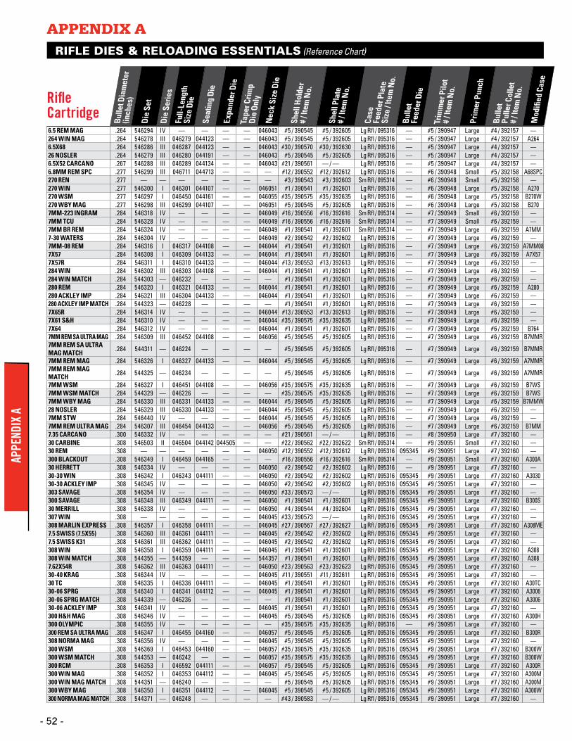
APPENDIX AAP
PEND
IX A
- 52 - - 52 -
RIFLE DIES & RELOADING ESSENTIALS (Reference Chart)
Rifle Cartridge
Bulle
t Dia
met
er
(inch
es)
Die
Set
Die
Serie
sFu
ll-Le
ngth
Si
ze D
ie
Seat
ing
Die
Expa
nder
Die
Tape
r Crim
p
Die
Only
Nec
k Si
ze D
ie
Shel
l Hol
der
# / I
tem
No.
Shel
l Pla
te
# / I
tem
No.
Case
Fe
eder
Pla
te
Size
/ Ite
m N
o.
Bulle
t Fe
eder
Die
Trim
mer
Pilo
t #
/ Ite
m N
o.
Prim
er P
unch
Bulle
t Pu
ller C
olle
t #
/ Ite
m N
o.
Mod
ified
Cas
e
6.5 REM MAG .264 546294 IV — — — — 046043 #5 / 390545 #5 / 392605 Lg Rfl / 095316 — #5 / 390947 Large #4 / 392157 —264 WIN MAG .264 546278 III 046279 044123 — — 046043 #5 / 390545 #5 / 392605 Lg Rfl / 095316 — #5 / 390947 Large #4 / 392157 A2646.5X68 .264 546286 III 046287 044123 — — 046043 #30 / 390570 #30 / 392630 Lg Rfl / 095316 — #5 / 390947 Large #4 / 392157 —26 NOSLER .264 546279 III 046280 044191 — — 046043 #5 / 390545 #5 / 392605 Lg Rfl / 095316 — #5 / 390947 Large #4 / 392157 —6.5X52 CARCANO .267 546288 III 046289 044134 — — 046043 #21 / 390561 — / — Lg Rfl / 095316 — #5 / 390947 Large #4 / 392157 —6.8MM REM SPC .277 546299 III 046711 044713 — — — #12 / 390552 #12 / 392612 Lg Rfl / 095316 — #6 / 390948 Small #5 / 392158 A68SPC270 REN .277 — — — — — — — #3 / 390543 #3 / 392603 Sm Rfl / 095314 — #6 / 390948 Small #5 / 392158 —270 WIN .277 546300 I 046301 044107 — — 046051 #1 / 390541 #1 / 392601 Lg Rfl / 095316 — #6 / 390948 Large #5 / 392158 A270270 WSM .277 546297 I 046450 044161 — — 046055 #35 / 390575 #35 / 392635 Lg Rfl / 095316 — #6 / 390948 Large #5 / 392158 B270W270 WBY MAG .277 546298 III 046299 044107 — — 046051 #5 / 390545 #5 / 392605 Lg Rfl / 095316 — #6 / 390948 Large #5 / 392158 B2707MM-223 INGRAM .284 546318 IV — — — — 046049 #16 / 390556 #16 / 392616 Sm Rfl / 095314 — #7 / 390949 Small #6 / 392159 —7MM TCU .284 546328 IV — — — — 046049 #16 / 390556 #16 / 392616 Sm Rfl / 095314 — #7 / 390949 Small #6 / 392159 —7MM BR REM .284 546324 IV — — — — 046049 #1 / 390541 #1 / 392601 Sm Rfl / 095314 — #7 / 390949 Large #6 / 392159 A7MM7-30 WATERS .284 546304 IV — — — — 046049 #2 / 390542 #2 / 392602 Lg Rfl / 095316 — #7 / 390949 Large #6 / 392159 —7MM-08 REM .284 546316 I 046317 044108 — — 046044 #1 / 390541 #1 / 392601 Lg Rfl / 095316 — #7 / 390949 Large #6 / 392159 A7MM087X57 .284 546308 I 046309 044133 — — 046044 #1 / 390541 #1 / 392601 Lg Rfl / 095316 — #7 / 390949 Large #6 / 392159 A7X577X57R .284 546311 I 046310 044133 — — 046044 #13 / 390553 #13 / 392613 Lg Rfl / 095316 — #7 / 390949 Large #6 / 392159 —284 WIN .284 546302 III 046303 044108 — — 046044 #1 / 390541 #1 / 392601 Lg Rfl / 095316 — #7 / 390949 Large #6 / 392159 —284 WIN MATCH .284 544303 — 046232 — — — — #1 / 390541 #1 / 392601 Lg Rfl / 095316 — #7 / 390949 Large #6 / 392159 —280 REM .284 546320 I 046321 044133 — — 046044 #1 / 390541 #1 / 392601 Lg Rfl / 095316 — #7 / 390949 Large #6 / 392159 A280280 ACKLEY IMP .284 546321 III 046304 044133 — — 046044 #1 / 390541 #1 / 392601 Lg Rfl / 095316 — #7 / 390949 Large #6 / 392159 —280 ACKLEY IMP MATCH .284 544323 — 046228 — — — — #1 / 390541 #1 / 392601 Lg Rfl / 095316 — #7 / 390949 Large #6 / 392159 —7X65R .284 546314 IV — — — — 046044 #13 / 390553 #13 / 392613 Lg Rfl / 095316 — #7 / 390949 Large #6 / 392159 —7X61 S&H .284 546310 IV — — — — 046044 #35 / 390575 #35 / 392635 Lg Rfl / 095316 — #7 / 390949 Large #6 / 392159 —7X64 .284 546312 IV — — — — 046044 #1 / 390541 #1 / 392601 Lg Rfl / 095316 — #7 / 390949 Large #6 / 392159 B7647MM REM SA ULTRA MAG .284 546309 III 046452 044108 — — 046056 #5 / 390545 #5 / 392605 Lg Rfl / 095316 — #7 / 390949 Large #6 / 392159 B7MMR7MM REM SA ULTRA MAG MATCH .284 544311 — 046224 — — — — #5 / 390545 #5 / 392605 Lg Rfl / 095316 — #7 / 390949 Large #6 / 392159 B7MMR
7MM REM MAG .284 546326 I 046327 044133 — — 046044 #5 / 390545 #5 / 392605 Lg Rfl / 095316 — #7 / 390949 Large #6 / 392159 A7MMR7MM REM MAG MATCH .284 544325 — 046234 — — — — #5 / 390545 #5 / 392605 Lg Rfl / 095316 — #7 / 390949 Large #6 / 392159 A7MMR
7MM WSM .284 546327 I 046451 044108 — — 046056 #35 / 390575 #35 / 392635 Lg Rfl / 095316 — #7 / 390949 Large #6 / 392159 B7WS7MM WSM MATCH .284 544329 — 046226 — — — — #35 / 390575 #35 / 392635 Lg Rfl / 095316 — #7 / 390949 Large #6 / 392159 B7WS7MM WBY MAG .284 546330 III 046331 044133 — — 046044 #5 / 390545 #5 / 392605 Lg Rfl / 095316 — #7 / 390949 Large #6 / 392159 B7MMW28 NOSLER .284 546329 III 046330 044133 — — 046044 #5 / 390545 #5 / 392605 Lg Rfl / 095316 — #7 / 390949 Large #6 / 392159 —7MM STW .284 546440 IV — — — — 046044 #5 / 390545 #5 / 392605 Lg Rfl / 095316 — #7 / 390949 Large #6 / 392159 —7MM REM ULTRA MAG .284 546307 III 046454 044133 — — 046056 #5 / 390545 #5 / 392605 Lg Rfl / 095316 — #7 / 390949 Large #6 / 392159 B7MM7.35 CARCANO .300 546332 IV — — — — — #21 / 390561 — / — Lg Rfl / 095316 — #8 / 390950 Large #7 / 392160 —30 CARBINE .308 546503 II 046504 044142 044505 — — #22 / 390562 #22 / 392622 Sm Rfl / 095314 — #9 / 390951 Small #7 / 392160 —30 REM .308 — — — — — — 046050 #12 / 390552 #12 / 392612 Lg Rfl / 095316 095345 #9 / 390951 Large #7 / 392160 —300 BLACKOUT .308 546349 I 046459 044165 — — — #16 / 390556 #16 / 392616 Sm Rfl / 095314 — #9 / 390951 Small #7 / 392160 A300A30 HERRETT .308 546334 IV — — — — 046050 #2 / 390542 #2 / 392602 Lg Rfl / 095316 — #9 / 390951 Large #7 / 392160 —30-30 WIN .308 546342 I 046343 044111 — — 046050 #2 / 390542 #2 / 392602 Lg Rfl / 095316 095345 #9 / 390951 Large #7 / 392160 A303030-30 ACKLEY IMP .308 546345 IV — — — — 046050 #2 / 390542 #2 / 392602 Lg Rfl / 095316 095345 #9 / 390951 Large #7 / 392160 —303 SAVAGE .308 546354 IV — — — — 046050 #33 / 390573 — / — Lg Rfl / 095316 095345 #9 / 390951 Large #7 / 392160 —300 SAVAGE .308 546348 III 046349 044111 — — 046050 #1 / 390541 #1 / 392601 Lg Rfl / 095316 095345 #9 / 390951 Large #7 / 392160 B300S30 MERRILL .308 546338 IV — — — — 046050 #4 / 390544 #4 / 392604 Lg Rfl / 095316 095345 #9 / 390951 Large #7 / 392160 —307 WIN .308 — — — — — — 046045 #33 / 390573 — / — Lg Rfl / 095316 095345 #9 / 390951 Large #7 / 392160 —308 MARLIN EXPRESS .308 546357 I 046358 044111 — — 046045 #27 / 390567 #27 / 392627 Lg Rfl / 095316 095345 #9 / 390951 Large #7 / 392160 A308ME7.5 SWISS (7.5X55) .308 546360 III 046361 044111 — — 046045 #2 / 390542 #2 / 392602 Lg Rfl / 095316 095345 #9 / 390951 Large #7 / 392160 —7.5 SWISS K31 .308 546361 III 046362 044111 — — 046045 #2 / 390542 #2 / 392602 Lg Rfl / 095316 095345 #9 / 390951 Large #7 / 392160 —308 WIN .308 546358 I 046359 044111 — — 046045 #1 / 390541 #1 / 392601 Lg Rfl / 095316 095345 #9 / 390951 Large #7 / 392160 A308308 WIN MATCH .308 544355 — 544359 — — — 544357 #1 / 390541 #1 / 392601 Lg Rfl / 095316 095345 #9 / 390951 Large #7 / 392160 A3087.62X54R .308 546362 III 046363 044111 — — 046050 #23 / 390563 #23 / 392623 Lg Rfl / 095316 095345 #9 / 390951 Large #7 / 392160 —30-40 KRAG .308 546344 IV — — — — 046045 #11 / 390551 #11 / 392611 Lg Rfl / 095316 095345 #9 / 390951 Large #7 / 392160 —30 TC .308 546335 I 046336 044111 — — 046045 #1 / 390541 #1 / 392601 Lg Rfl / 095316 095345 #9 / 390951 Large #7 / 392160 A30TC30-06 SPRG .308 546340 I 046341 044112 — — 046045 #1 / 390541 #1 / 392601 Lg Rfl / 095316 095345 #9 / 390951 Large #7 / 392160 A300630-06 SPRG MATCH .308 544339 — 046236 — — — — #1 / 390541 #1 / 392601 Lg Rfl / 095316 095345 #9 / 390951 Large #7 / 392160 A300630-06 ACKLEY IMP .308 546341 IV — — — — 046045 #1 / 390541 #1 / 392601 Lg Rfl / 095316 095345 #9 / 390951 Large #7 / 392160 —300 H&H MAG .308 546346 IV — — — — 046045 #5 / 390545 #5 / 392605 Lg Rfl / 095316 095345 #9 / 390951 Large #7 / 392160 A300H300 OLYMPIC .308 546355 IV — — — — — #35 / 390575 #35 / 392635 Lg Rfl / 095316 — #9 / 390951 Large #7 / 392160 —300 REM SA ULTRA MAG .308 546347 I 046455 044160 — — 046057 #5 / 390545 #5 / 392605 Lg Rfl / 095316 095345 #9 / 390951 Large #7 / 392160 B300R308 NORMA MAG .308 546356 IV — — — — 046045 #5 / 390545 #5 / 392605 Lg Rfl / 095316 095345 #9 / 390951 Large #7 / 392160 —300 WSM .308 546369 I 046453 044160 — — 046057 #35 / 390575 #35 / 392635 Lg Rfl / 095316 095345 #9 / 390951 Large #7 / 392160 B300W300 WSM MATCH .308 544353 — 046242 — — — 046057 #35 / 390575 #35 / 392635 Lg Rfl / 095316 095345 #9 / 390951 Large #7 / 392160 B300W300 RCM .308 546353 I 046592 044111 — — 046057 #5 / 390545 #5 / 392605 Lg Rfl / 095316 095345 #9 / 390951 Large #7 / 392160 A300R300 WIN MAG .308 546352 I 046353 044112 — — 046045 #5 / 390545 #5 / 392605 Lg Rfl / 095316 095345 #9 / 390951 Large #7 / 392160 A300M300 WIN MAG MATCH .308 544351 — 046240 — — — — #5 / 390545 #5 / 392605 Lg Rfl / 095316 095345 #9 / 390951 Large #7 / 392160 A300M300 WBY MAG .308 546350 I 046351 044112 — — 046045 #5 / 390545 #5 / 392605 Lg Rfl / 095316 095345 #9 / 390951 Large #7 / 392160 A300W300 NORMA MAG MATCH .308 544371 — 046248 — — — — #43 / 390583 — / — Lg Rfl / 095316 095345 #9 / 390951 Large #7 / 392160 —
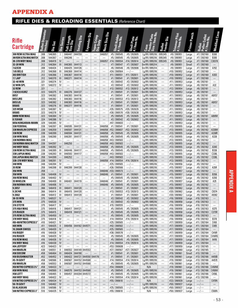
APPENDIX AAPPENDIX A
- 53 -
RIFLE DIES & RELOADING ESSENTIALS (Reference Chart)
Rifle Cartridge
Bulle
t Dia
met
er
(inch
es)
Die
Set
Die
Serie
sFu
ll-Le
ngth
Si
ze D
ie
Seat
ing
Die
Expa
nder
Die
Tape
r Crim
p
Die
Only
Nec
k Si
ze D
ie
Shel
l Hol
der
# / I
tem
No.
Shel
l Pla
te
# / I
tem
No.
Case
Fe
eder
Pla
te
Size
/ Ite
m N
o.
Bulle
t Fe
eder
Die
Trim
mer
Pilo
t #
/ Ite
m N
o.
Prim
er P
unch
Bulle
t Pu
ller C
olle
t #
/ Ite
m N
o.
Mod
ified
Cas
e
300 REM ULTRA MAG .308 546365 I 046447 044159 — — 046057 #5 / 390545 #5 / 392605 Lg Rfl / 095316 095345 #9 / 390951 Large #7 / 392160 B300300 REM ULTRA MAG MATCH .308 544367 — 046246 — — — — #5 / 390545 #5 / 392605 Lg Rfl / 095316 095345 #9 / 390951 Large #7 / 392160 B30030-378 WBY MAG .308 546419 IV — — — — 046057 #14 / 390554 #14 / 392614 Lg Rfl / 095316 095345 #9 / 390951 Large #7 / 392160 C3037832-20 WIN .312 546364 III 046365 044113 — — — #7 / 390547 #7 / 392607 Sm Rfl / 095314 — #9 / 390951 Small #7 / 392160 —7.62X39 .308 546424 I 046425 044126 — — — #6 / 390546 #6 / 392606 Sm Rfl / 095314 — #9 / 390951 Large #7 / 392160 A7627.65 BELG .312 546368 III 046369 044114 — — — #24 / 390564 — / — Lg Rfl / 095316 — #10 / 390952 Large #7 / 392160 —303 BRITISH .312 546366 I 046367 044114 — — — #11 / 390551 #11 / 392611 Lg Rfl / 095316 — #10 / 390952 Large #7 / 392160 A3037.7 JAP .312 546370 III 046371 044114 — — — #1 / 390541 #1 / 392601 Lg Rfl / 095316 — #10 / 390952 Large #7 / 392160 —32-40 WIN .321 546374 IV — — — — — #2 / 390542 #2 / 392602 Lg Rfl / 095316 — #11 / 390953 Large #8 / 392161 —32 WIN SPL .321 546372 IV — — — — — #2 / 390542 #2 / 392602 Lg Rfl / 095316 — #11 / 390953 Large #8 / 392161 A3232 REM .321 — — — — — — — #12 / 390552 #12 / 392612 Lg Rfl / 095316 — #12 / 390954 Large #8 / 392161 —7.92X33 KURZ .323 546375 III 046376 044137 — — — #1 / 390541 #1 / 392601 Sm Rfl / 095314 — #11 / 390953 Large #8 / 392161 —8X57 .323 546382 I 046383 044116 — — — #1 / 390541 #1 / 392601 Lg Rfl / 095316 — #11 / 390953 Large #8 / 392161 A8X578X57JRS .323 546382 I 046383 044116 — — — #13 / 390553 #13 / 392613 Lg Rfl / 095316 — #11 / 390953 Large #8 / 392161 —8X57JS .323 546382 I 046383 044116 — — — #1 / 390541 #1 / 392601 Lg Rfl / 095316 — #11 / 390953 Large #8 / 392161 A8X578X60S .323 546376 III 046377 044116 — — — #1 / 390541 #1 / 392601 Lg Rfl / 095316 — #11 / 390953 Large #8 / 392161 —325 WSM .323 546387 IV — — — — — #35 / 390575 #35 / 392635 Lg Rfl / 095316 — #11 / 390953 Large #8 / 392161 —8X68S .323 546378 IV — — — — — #30 / 390570 #30 / 392630 Lg Rfl / 095316 — #11 / 390953 Large #8 / 392161 —8MM REM MAG .323 546384 IV — — — — — #5 / 390545 #5 / 392605 Lg Rfl / 095316 — #11 / 390953 Large #8 / 392161 A8MM8.15X46R .324 546386 IV — — — — — #2 / 390542 #2 / 392602 Lg Rfl / 095316 — #11 / 390953 Large #8 / 392161 —8X56 HUNGARIAN-MANN .329 546385 IV — — — — — #47 / 390603 — / — Lg Rfl / 095316 — #11 / 390953 Large #8 / 392161 —338 FEDERAL .338 546397 III 046595 044131 — — 046058 #1 / 390541 #1 / 392601 Lg Rfl / 095316 — #13 / 390955 Large #9 / 392162 —338 MARLIN EXPRESS .338 546359 I 046597 044131 — — 046058 #52 / 390607 #52 / 392652 Lg Rfl / 095316 — #13 / 390955 Large #9 / 392162 A338M338 RCM .338 546399 I 046594 044131 — — 046058 #5 / 390545 #5 / 392605 Lg Rfl / 095316 — #13 / 390955 Large #9 / 392162 A338R338 WIN MAG .338 546390 I 046391 044117 — — 046058 #5 / 390545 #5 / 392605 Lg Rfl / 095316 — #13 / 390955 Large #9 / 392162 A338338 NORMA MAG .338 — — — — — — 046058 #43 / 390583 — / — Lg Rfl / 095316 — #13 / 390955 Large #9 / 392162 —338 NORMA MAG MATCH .338 544397 — 046250 — — — 046058 #43 / 390583 — / — Lg Rfl / 095316 — #13 / 390955 Large #9 / 392162 —340 WBY MAG .338 546392 IV — — — — 046058 #5 / 390545 #5 / 392605 Lg Rfl / 095316 — #13 / 390955 Large #9 / 392162 A340338 REM ULTRA MAG .338 546389 III 046446 044117 — — 046058 #5 / 390545 #5 / 392605 Lg Rfl / 095316 — #13 / 390955 Large #9 / 392162 B338338 LAPUA MAG .338 546393 III 046593 044117 — — 046058 #43 / 390583 — / — Lg Rfl / 095316 — #13 / 390955 Large #9 / 392162 C338L338 LAPUA MAG MATCH .358 544399 — 046252 — — — — #43 / 390583 — / — Lg Rfl / 095316 — #13 / 390955 Large #9 / 392162 C338L338-378 WBY MAG .338 546391 IV — — — — 046058 #14 / 390554 #14 / 392614 Lg Rfl / 095316 — #13 / 390955 Large #9 / 392162 —348 WIN .348 546394 IV — — — — — #25 / 390565 — / — Lg Rfl / 095316 — #14 / 390956 Large #9 / 392162 —35 REM .358 546398 III 046399 044130 — — — #26 / 390566 — / — Lg Rfl / 095316 — #15 / 390957 Large #9 / 392162 A35R356 WIN .358 — — — — — — 046046 #33 / 390573 — / — Lg Rfl / 095316 — #15 / 390957 Large #9 / 392162 —358 WIN .358 546408 IV — — — — 046046 #1 / 390541 #1 / 392601 Lg Rfl / 095316 — #15 / 390957 Large #9 / 392162 B358350 REM MAG .358 546402 IV — — — — — #5 / 390545 #5 / 392605 Lg Rfl / 095316 — #15 / 390957 Large #9 / 392162 A35035 WHELEN .358 546400 III 046401 044119 — — 046046 #1 / 390541 #1 / 392601 Lg Rfl / 095316 — #15 / 390957 Large #9 / 392162 A35358 NORMA MAG .358 546406 IV — — — — 046046 #5 / 390545 #5 / 392605 Lg Rfl / 095316 — #15 / 390957 Large #9 / 392162 —9.3X57 .366 546410 III 046411 044120 — — — #1 / 390541 #1 / 392601 Lg Rfl / 095316 — #20 / 390962 Large #9 / 392162 —9.3X74R .366 546414 III 046415 044120 — — — #13 / 390553 #13 / 392613 Lg Rfl / 095316 — #20 / 390962 Large #9 / 392162 C93749.3X62 .366 546412 III 046413 044120 — — — #1 / 390541 #1 / 392601 Lg Rfl / 095316 — #20 / 390962 Large #9 / 392162 A936238-55 WIN .375 546537 IV — — — — — #2 / 390542 #2 / 392602 Lg Rfl / 095316 — #16 / 390958 Large #10 / 392163 —375 WIN .375 546530 IV — — — — — #2 / 390542 #2 / 392602 Lg Rfl / 095316 — #16 / 390958 Large #10 / 392163 —376 STEYR .375 546417 IV — — — — — #15 / 390555 — / — Lg Rfl / 095316 — #16 / 390958 Large #10 / 392163 —375 H&H MAG .375 546416 I 046417 044121 — — — #5 / 390545 #5 / 392605 Lg Rfl / 095316 — #16 / 390958 Large #10 / 392163 A375375 RUGER .375 546415 I 046418 044121 — — — #5 / 390545 #5 / 392605 Lg Rfl / 095316 — #16 / 390958 Large #10 / 392163 C375R375 REM ULTRA MAG .375 546450 IV — — — — — #5 / 390545 #5 / 392605 Lg Rfl / 095316 — #16 / 390958 Large #10 / 392163 —378 WBY MAG .375 546418 IV — — — — — #14 / 390554 #14 / 392614 Lg Rfl / 095316 — #16 / 390958 Large #10 / 392163 B378450-400 NITRO EXPRESS 3” .410 546421 IV — — — — — #25 / 390565 — / — Lg Rfl / 095316 — #17 / 390959 Large #11 / 392164 C450405 WIN .411 546425 II 046456 044162 044571 — — #42 / 390582 — / — Lg Rfl / 095316 — #17 / 390959 Large #11 / 392164 C40510.3X60R SWISS .415 546420 IV — — — — — #25 / 390565 — / — Lg Rfl / 095316 — #17 / 390959 Large #11 / 392164 —416 RIGBY .416 546428 IV — — — — — #38 / 390578 — / — Lg Rfl / 095316 — #17 / 390959 Large #11 / 392164 C416R416 RUGER .416 546429 IV — — — — — #5 / 390545 #5 / 392605 Lg Rfl / 095316 — #17 / 390959 Large #11 / 392164 C416RG416 REM MAG .416 546426 IV — — — — — #5 / 390545 #5 / 392605 Lg Rfl / 095316 — #17 / 390959 Large #11 / 392164 A416416 WBY MAG .416 546430 IV — — — — — #14 / 390554 #14 / 392614 Lg Rfl / 095316 — #17 / 390959 Large #11 / 392164 —404 JEFFERY .423 546423 IV — — — — — #53 / 390608 — / — Lg Rfl / 095316 — #17 / 390959 Large #12 / 392165 —444 MARLIN .430 546551 II 046552 044149 044553 — — #27 / 390567 #27 / 392627 Lg Rfl / 095316 — #18 / 390960 Large #12 / 392165 —458 SOCOM .458 546464 III 046424 044190 — — — #1 / 390541 #1 / 392601 Lg Rfl / 095316 — #19 / 390961 Small #13 / 392166 —450 BUSHMASTER .452 546452 V 046422 044721 044550 044176 — #1 / 390541 #1 / 392601 Lg Rfl / 095316 — #19 / 390961 Large #13 / 392166 A450B45-70 GOVT .458 546566 II 046567 044152 044568 — — #14 / 390554 #14 / 392614 Lg Rfl / 095316 — #19 / 390961 Large #13 / 392166 A4570450 MARLIN .458 546553 II 046587 044152 044568 — — #5 / 390545 #5 / 392605 Lg Rfl / 095316 — #19 / 390961 Large #13 / 392166 —450 NITRO EXPRESS 3¼” .458 546433 IV — — — — — #54 / 390609 — / — N/A — #19 / 390961 Large #13 / 392166 C450NE458 WIN MAG .458 546569 II 046570 044153 044568 — — #5 / 390545 #5 / 392605 Lg Rfl / 095316 — #19 / 390961 Large #13 / 392166 C458W458 LOTT .458 546465 II 046457 044204 044572 — — #5 / 390545 #5 / 392605 Lg Rfl / 095316 — #19 / 390961 Large #13 / 392166 C458L460 WBY MAG .458 546422 IV — — — — — #14 / 390554 #14 / 392614 Lg Rfl / 095316 — #19 / 390961 Large #13 / 392166 —470 NITRO EXPRESS 3¼” .474 546434 IV — — — — — #55 / 390610 — / — N/A — #23 / 390939 Large — / — C470N50-70 GOVT .510 546462 IV — — — — — — / — — / — Lg Rfl / 095316 — #50 / 390937 Large — / — —50 ALASKAN .510 546586 IV — — — — — #25 / 390565 — / — Lg Rfl / 095316 — #50 / 390937 Large — / — —500 NITRO EXPRESS 3” .510 546435 IV — — — — — #55 / 390610 — / — N/A — #50 / 390937 Large — / — C500N
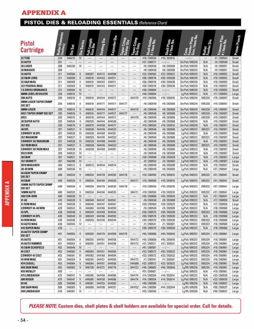
PISTOL DIES & RELOADING ESSENTIALS (Reference Chart)
Pistol Cartridge
Bulle
t Dia
met
er
(inch
es)
Die
Set
Die
Serie
sFu
ll-Le
ngth
Si
ze D
ie
Seat
ing
Die
Expa
nder
Die
Tape
r Crim
p Se
ater
Die
Tape
r Crim
p
Die
Only
Shel
l Hol
der
# / I
tem
No.
Shel
l Pla
te
# / I
tem
No.
Case
Fe
eder
Pla
te
Size
/ Ite
m N
o.
Bulle
t Fe
eder
Die
Trim
mer
Pilo
t #
/ Ite
m N
o.
Prim
er P
unch
22 TCM .224 546215 IV — — — — — #16 / 390556 #16 / 392616 — / — — #1 / 390943 Small25 AUTO .251 — — — — — — — #37 / 390577 — / — Sm Pstl / 095310 N/A #4 / 390946 Small30 LUGER .308 546336 IV — — — — — #8 / 390548 #8 / 392608 Sm Pstl / 095310 N/A #9 / 390951 Small30 MAUSER .309 — — — — — — — #8 / 390548 #8 / 392608 Sm Pstl / 095310 N/A #9 / 390951 Small32 AUTO .311 546506 II 046507 044113 044508 — — #22 / 390562 #22 / 392622 Sm Pstl / 095310 N/A #10 / 390952 Small32 S&W LONG .311 546509 II 046510 044143 044511 — — #36 / 390576 #36 / 392636 Sm Pstl / 095310 N/A #10 / 390952 Small32 H&R MAG .311 546509 II 046510 044143 044511 — — #36 / 390576 #36 / 392636 Sm Pstl / 095310 N/A #10 / 390952 Small327 FEDERAL MAG .311 546509 II 046510 044143 044511 — — #36 / 390576 #36 / 392636 Sm Pstl / 095310 N/A #10 / 390952 Small7.5 SWISS ORDNANCE .312 546504 IV — — — — — #48 / 390604 — / — Sm Pstl / 095310 N/A #10 / 390952 Small8MM LEBEL REVOLVER .326 546510 IV — — — — — #48 / 390604 — / — Lg Pstl / 095312 N/A #11 / 390953 Large380 AUTO .355 546518 II 046519 044144 044517 — 044170 #16 / 390556 #16 / 392616 Sm Pstl / 095310 095330 #15 / 390957 Small9MM LUGER TAPER CRIMP DIE SET .355 546516 II 046516 044177 044517 044177 — #8 / 390548 #8 / 392608 Sm Pstl / 095310 095330 #15 / 390957 Small
9MM LUGER .355 546515 II 046516 044144 044517 — 044170 #8 / 390548 #8 / 392608 Sm Pstl / 095310 095330 #15 / 390957 Small9X21 TAPER CRIMP DIE SET .355 546516 II 046516 044177 044517 044177 — #8 / 390548 #8 / 392608 Sm Pstl / 095310 095330 #15 / 390957 Small9X21 .355 546515 II 046516 044144 044517 — 044170 #8 / 390548 #8 / 392608 Sm Pstl / 095310 095330 #15 / 390957 Small38 SUPER AUTO .355 546524 II 046525 044144 044526 — — #8 / 390548 #8 / 392608 Sm Pstl / 095310 N/A #15 / 390957 Small357 SIG .355 546575 II 046576 044150 044577 — — #10 / 390550 #10 / 392610 Sm Pstl / 095310 N/A #15 / 390957 Small38 SPL .357 546527 II 046528 044145 044523 — — #6 / 390546 #6 / 392606 Lg Pstl / 095312 095331 #15 / 390957 SmallCOWBOY 38 SPL .357 546528 III 046528 044169 044591 — — #6 / 390546 #6 / 392606 Lg Pstl / 095312 N/A #15 / 390957 Small357 MAGNUM .357 546527 II 046528 044145 044523 — — #6 / 390546 #6 / 392606 Lg Pstl / 095312 095331 #15 / 390957 SmallCOWBOY 357 MAGNUM .357 546528 III 046528 044169 044591 — — #6 / 390546 #6 / 392606 Lg Pstl / 095312 N/A #15 / 390957 Small357 REM MAX .357 546527 II 046528 044145 044523 — — #6 / 390546 #6 / 392606 Lg Pstl / 095312 095331 #15 / 390957 SmallCOWBOY 357 REM MAX .357 546528 III 046528 044169 044591 — — #6 / 390546 #6 / 392606 Lg Pstl / 095312 N/A #15 / 390957 Small9X23 WIN .355 546532 IV — — — — — #8 / 390548 #8 / 392608 Sm Pstl / 095310 N/A #15 / 390957 Small38 S&W .357 546521 IV — — — — — #28 / 390568 #28 / 392628 Lg Pstl / 095312 N/A #15 / 390957 Large357 HERRETT .357 546396 IV — — — — — #2 / 390542 #2 / 392602 Lg Pstl / 095312 N/A #15 / 390957 Large9X18 MAKAROV .364 546512 II 046513 044154 044514 — — #8 / 390548 #8 / 392608 Sm Pstl / 095310 N/A #15 / 390957 Small38-40 WIN .400 546536 IV — — — — — #9 / 390549 #9 / 392609 Lg Pstl / 095312 N/A #21 / 390941 Large40 S&W TAPER CRIMP DIE SET .400 546534 II 046534 044178 044535 044178 — #10 / 390550 #10 / 392610 Lg Pstl / 095312 095332 #21 / 390941 Small
40 S&W .400 546533 II 046534 044146 044535 — 044171 #10 / 390550 #10 / 392610 Lg Pstl / 095312 095332 #21 / 390941 Small10MM AUTO TAPER CRIMP DIE SET .400 546534 II 046534 044178 044535 044178 — #10 / 390550 #10 / 392610 Lg Pstl / 095312 095332 #21 / 390941 Large
10MM AUTO .400 546533 II 046534 044146 044535 — 044171 #10 / 390550 #10 / 392610 Lg Pstl / 095312 095332 #21 / 390941 Large400 COR-BON .400 546538 IV — — — — — #45 / 390606 #45 / 392645 Lg Pstl / 095312 N/A #21 / 390941 Large41 AE .410 546539 II 046540 044147 044541 — — #8 / 390548 #8 / 392608 Lg Pstl / 095312 N/A #17 / 390959 Small41 REM MAG .410 546539 II 046540 044147 044541 — — #29 / 390569 #29 / 392629 Lg Pstl / 095312 N/A #17 / 390959 LargeCOWBOY 44-40 WIN .429 546543 III 046460 044166 044593 — — #9 / 390549 #9 / 392609 Lg Pstl / 095312 N/A #18 / 390960 Large44 SPL .430 546548 II 046549 044148 044544 — — #30 / 390570 #30 / 392630 Lg Pstl / 095312 095333 #18 / 390960 LargeCOWBOY 44 SPL .430 546549 III 046549 044166 044592 — — #30 / 390570 #30 / 392630 Lg Pstl / 095312 N/A #18 / 390960 Large44 REM MAG .430 546548 II 046549 044148 044544 — — #30 / 390570 #30 / 392630 Lg Pstl / 095312 095333 #18 / 390960 Large44 AUTO MAG .430 546545 IV — — — — — #1 / 390541 #1 / 392601 Lg Pstl / 095312 095333 #18 / 390960 Large445 SUPER MAG .430 — — — — — — — #30 / 390570 #30 / 392630 Lg Pstl / 095312 N/A #18 / 390960 Large45 AUTO TAPER CRIMP DIE SET .451 546555 II 046555 044179 044556 044179 — #45 / 390606 #45 / 392645 Lg Pstl / 095312 095334 #19 / 390961 Large
45 AUTO .451 546554 II 046555 044151 044556 — 044172 #45 / 390606 #45 / 392645 Lg Pstl / 095312 095334 #19 / 390961 Large45 AUTO RIMMED .451 546554 II 046555 044151 044556 — 044172 #31 / 390571 #31 / 392631 Lg Pstl / 095312 095334 #19 / 390961 Large45 S&W SCHOFIELD .452 546546 IV — — — — — #41 / 390581 — / — Lg Pstl / 095312 095334 #19 / 390961 Large45 COLT .452 546582 II 046583 044151 044556 — — #32 / 390572 #32 / 392632 Lg Pstl / 095312 095334 #19 / 390961 LargeCOWBOY 45 COLT .452 546581 III 046583 044168 044594 — — #32 / 390572 #32 / 392632 Lg Pstl / 095312 095334 #19 / 390961 Large45 WIN MAG .451 546554 II 046555 044151 044556 — 044172 #1 / 390541 #1 / 392601 Lg Pstl / 095312 095334 #19 / 390961 Large454 CASULL .452 546584 V 046584 044151 044556 — 044588 #32 / 390572 #32 / 392632 Lg Pstl / 095312 095334 #19 / 390961 Small460 S&W MAG .452 546583 V 046720 044721 044719 — 044722 #46 / 390602 #46 / 392646 Lg Rfl / 095316 095334 #19 / 390961 Large455 WEBLEY .455 — — — — — — — #51 / 390601 — / — Lg Pstl / 095312 N/A #19 / 390961 Large475 LINEBAUGH .475 546547 V 046585 044158 044586 — 044174 #14 / 390554 #14 / 392614 Lg Pstl / 095312 N/A #23 / 390939 Large480 RUGER .475 546547 V 046585 044158 044586 — 044174 #14 / 390554 #14 / 392614 Lg Pstl / 095312 N/A #23 / 390939 Large50 AE .500 546580 II 046581 044155 044582 — — #40 / 390580 — / — Lg Rfl / 095316 N/A #50 / 390937 Large500 S&W MAG .500 546585 V 046699 044700 044701 — 044702 #44 / 390584 #44 / 392644 Lg Rfl / 095316 N/A #50 / 390937 Large500 LINEBAUGH .510 546587 IV — — — — — #25 / 390565 — / — Lg Rfl / 095316 N/A #50 / 390937 Large
PLEASE NOTE: Custom dies, shell plates & shell holders are available for special order. Call for details.
APPENDIX AAP
PEND
IX A
- 54 - - 54 -
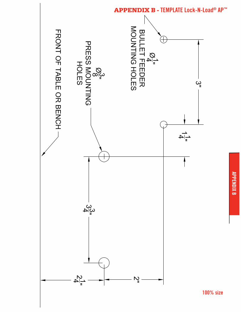
100% size
APPENDIX B - TEMPLATE Lock-N-Load® AP™APPENDIX B

110V - No. 095160220V - No. 095165
P.O. Box 1848, Grand Island, Nebraska 68802-1848 308-382-1390 • 800-338-3220 • Fax: 308-382-5761
www.hornady.com • Hornady.com/contact_us 07/2018
680023-REV4