local post buckling: an efficient analysis approach for...
TRANSCRIPT

1 American Institute of Aeronautics and Astronautics
Local Post Buckling: An Efficient Analysis Approach for Industry Use
Craig Collier1 and Phil Yarrington2 [email protected]
Collier Research Corp., Hampton, VA
Pete Gustafson3 Western Michigan University
Brett Bednarcyk4
NASA Glenn Research Center, Cleveland, OH
Aerospace metallic and composite laminate stiffened panels also called “skin-stringer panels” are designed to support load beyond local buckling of the skin. This design approach requires a method to quantify post buckled collapse strength of the panel. This paper presents an accurate and computationally efficient analysis method intended for broad industry usage based on a rapid, iterative convergence of both the ‘effective width’ of unbuckled skin and convergence of the updated overall panel stiffness and resulting internal load redistribution. The method is implemented into the HyperSizer® software. Verifications to Abaqus® non-linear FEA and validations to test data are included.
© 2008 Collier Research Corporation. Published by the American Institute of Aeronautics and Astronautics, Inc., with permission. 1, 2 Senior Research Engineers, Hampton, Virginia; AIAA Senior Member, [email protected] 3 Peter A. Gustafson, Assistant Professor, Department of Mechanical and Aeronautical Engineering, Western Michigan University, Kalamazoo Michigan, Member, AIAA, 4 Materials Research Engineer, AIAA Senior Member, [email protected]
50th AIAA/ASME/ASCE/AHS/ASC Structures, Structural Dynamics, and Materials Conference <br>17th4 - 7 May 2009, Palm Springs, California
AIAA 2009-2507
Copyright © 2009 by Copyright (c) 2009 by Collier Research Corporation. Published by the American Institute of Aeronautics and Astronautics, Inc., with permission.
2 American Institute of Aeronautics and Astronautics
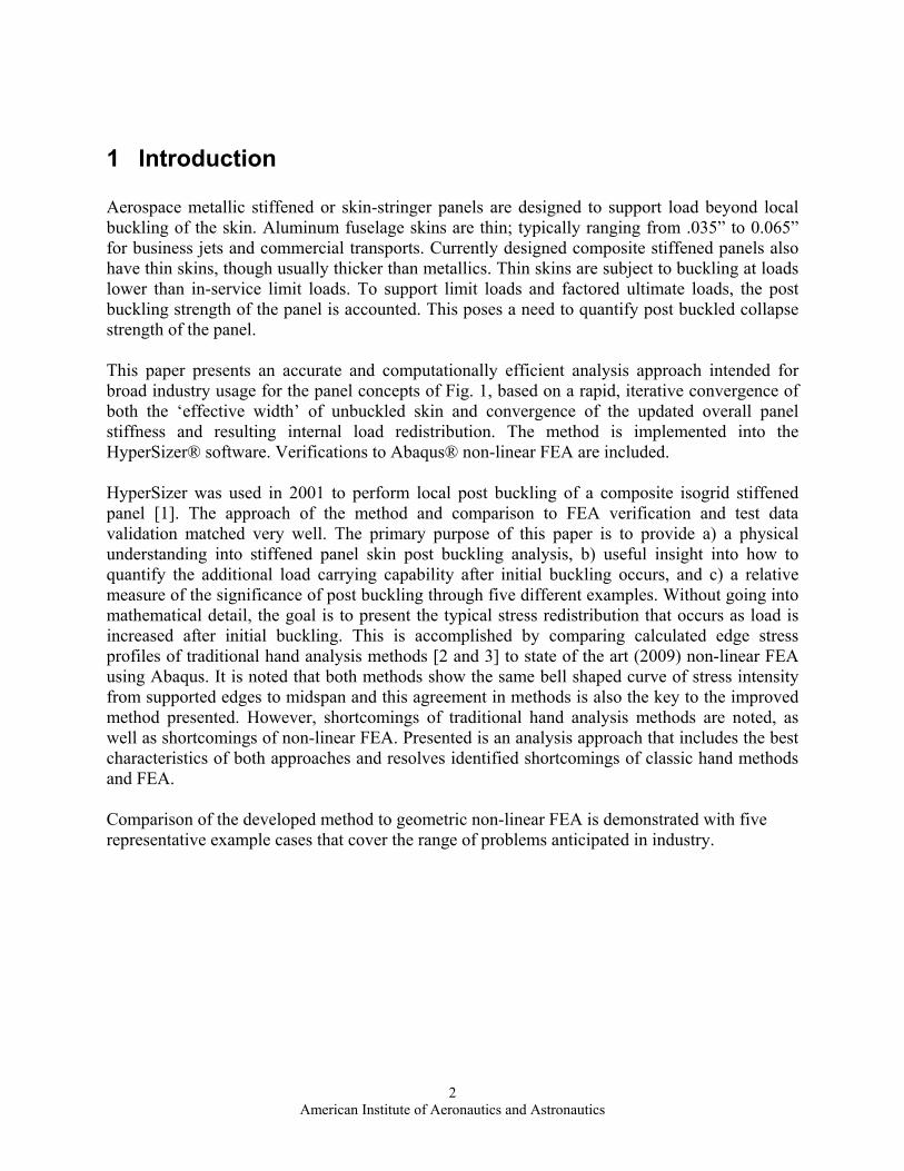
1 Introduction Aerospace metallic stiffened or skin-stringer panels are designed to support load beyond local buckling of the skin. Aluminum fuselage skins are thin; typically ranging from .035” to 0.065” for business jets and commercial transports. Currently designed composite stiffened panels also have thin skins, though usually thicker than metallics. Thin skins are subject to buckling at loads lower than in-service limit loads. To support limit loads and factored ultimate loads, the post buckling strength of the panel is accounted. This poses a need to quantify post buckled collapse strength of the panel. This paper presents an accurate and computationally efficient analysis approach intended for broad industry usage for the panel concepts of Fig. 1, based on a rapid, iterative convergence of both the ‘effective width’ of unbuckled skin and convergence of the updated overall panel stiffness and resulting internal load redistribution. The method is implemented into the HyperSizer® software. Verifications to Abaqus® non-linear FEA are included. HyperSizer was used in 2001 to perform local post buckling of a composite isogrid stiffened panel [1]. The approach of the method and comparison to FEA verification and test data validation matched very well. The primary purpose of this paper is to provide a) a physical understanding into stiffened panel skin post buckling analysis, b) useful insight into how to quantify the additional load carrying capability after initial buckling occurs, and c) a relative measure of the significance of post buckling through five different examples. Without going into mathematical detail, the goal is to present the typical stress redistribution that occurs as load is increased after initial buckling. This is accomplished by comparing calculated edge stress profiles of traditional hand analysis methods [2 and 3] to state of the art (2009) non-linear FEA using Abaqus. It is noted that both methods show the same bell shaped curve of stress intensity from supported edges to midspan and this agreement in methods is also the key to the improved method presented. However, shortcomings of traditional hand analysis methods are noted, as well as shortcomings of non-linear FEA. Presented is an analysis approach that includes the best characteristics of both approaches and resolves identified shortcomings of classic hand methods and FEA. Comparison of the developed method to geometric non-linear FEA is demonstrated with five representative example cases that cover the range of problems anticipated in industry.

3 American Institute of Aeronautics and Astronautics
Fig.1, Typical airframe stiffened panel concepts that are designed and analyzed for post buckling.

4 American Institute of Aeronautics and Astronautics
2 The Physics of Local Post Buckling Stiffened panels have high buckling stability and are efficient at supporting compression loading. The lowest failure mode of a stiffened panel is usually local buckling of the skin between stiffeners. After the skin local buckles, the stiffened panel can continue to support more load. Allowing the stiffened panel to local buckle at operational loads requires a local post buckling analysis capability.
Fig.2, A bulb Tee stiffened panel with a depicted local buckling mode shape. Illustrated in Fig. 3 is the sequence of local buckling. 1st an initial bifurcation local buckling mode occurs, green line. 2nd, additional load causes the mode shape amplitude to be greater, blue line. 3rd, as the full local post buckling strength is realized, the mode shape becomes its largest, red line. As load is increased, the buckling mode shape becomes larger, and the effective width, be, of the remaining stable skin becomes narrower. Note that the effective width is dynamic and does not necessarily have to intersect the end of the flange taper.
Fig.3, Different local panel mode amplifications due to progressive compression loading and the resulting remaining stable effective width, be.
A panel span (usually the facesheet that spans stiffeners) is able to carry additional load after it local buckles due to its remaining effective width. Furthermore, the panel as a whole is also able to carry additional load due to its remaining stable cross section. Local buckling of the skin at operating load occurs due to a relatively wide width in comparison to sheet thickness (a high b/t ratio). Local post buckling of a span is permissible if the panel can be shown to support additional load beyond the first occurrence of buckling (bifurcation point), without strength failure or collapse from buckling or cross section crippling. In aerospace designs, the spans are allowed to local buckle even at limit loads, but normally not at loads below a prescribed level, such as 0.5 Design Limit Load (DLL).

5 American Institute of Aeronautics and Astronautics
The approach for analyzing local post buckling of stiffened panels presented here is to load the panel cross section and determine which, if any, span objects local buckle. A span object could be a stiffener web, a stiffener flange, or a portion of the facesheet. For aerospace applications, it is customary to allow the facesheet between the stiffeners of a skin-stringer design to local buckle at a load below the overall design-to load. The stiffener, as a strip-column, is designed to carry the additional compressive and overall bending moments of the panel. The unbuckled portion of the skin that has an effective width is included in the stiffener’s cross section properties for additional loading past the point of bifurcation. As an example, consider a metallic Zee stiffened panel, Fig. 4a and 4b, that is loaded in uniform compression, or more accurately described by an applied uniform end shortening. At the onset of skin buckling (local buckling) the analysis is linear elastic, and all of the panel objects such as the skin, stiffener web, and stiffener flange are all at the same stress level. This level of stress is depicted as the horizontal dashed line in figure 4c. As additional load is applied to the panel, the buckled skin between stiffeners remains at the same stress (constant bifurcation load) and the additional load is picked up by the stiffener and the remaining effective width, be of the skin. As more load is applied the effective width becomes more narrow and the remaining stable cross section of skin and stringer carries a higher stress, until either the material reaches compressive yield, the strip-column buckles, or the stiffener cripples. The actual state of stress distribution of Fig 4d is represented with a rectangular step function, as shown in Fig. 4e
be be
B
FcAs more loadis applied, b becomesmore narrow
e
be3
be2be1
Peak stress is limited byForForsome other failure
c,st
cylC
A
Fig. 4, The effective width of the facesheet is included with the stiffener in the calculation of remaining panel stable cross section. As load is increased the remaining effective width becomes narrower.
Costant stress at the onset of local buckling

6 American Institute of Aeronautics and Astronautics
Therefore we observe the effective width is a function of the referenced stress, Fc. For stiffened cross sections hand methods use for this referenced Fc, the collapse load of the stringer, Fc,st, which is either the limiting allowable crippling stress of the stringer, a buckling-crippling interaction stress such as Johnson- Euler, or the compressive yield stress of the material. The presented method uses the actual state of stress in the panel objects for each loadcase, and as an internal check, verifies that the integration of inelastic stresses over their corresponding widths is equal to the applied loading.
3 Significance of Local Post Buckling Figure 5 quantifies the residual strength remaining after local buckling for two typical cases. The relative increase in ultimate load beyond initial buckling is 600% for this thin metallic sheet, and 230% for this composite laminate.
3.1 Significance of Presented Analysis Method The verification FEM for the first case presented is the most simplistic unstiffened isotropic problem. The geometric and material non-linear FEA required 21,000 elements and 2 hours to run the non-linear solution and post process the results. This does not include pre-processing time to build the model and determine the correct boundary conditions. The objective of the developed method is to provide a method that runs in less than 0.1 second and is robust and easily adapted by an engineering group for their design project.
Fig. 5, Additional load carrying capability after initial buckling occurs. Typical thickness of metal skin and composite laminate.

7 American Institute of Aeronautics and Astronautics
• Accounts for biaxial and shear loads. Not only are compressive axial loads used, but also
biaxial loadings, including tension field hoop effects, shear loadings, and bending moments including beam-column. (For instance, effective widths are computed for a facesheet in compression caused from bending moments)
• Supports any general composite layup. Full support for composite orthotropic materials. • Automatically re-distributes load and performs strength analysis, etc. based on re-
distributed loads • Tracks separately the bifurcation load of the buckled skin from the remaining stable cross
section • The corresponding redistribution of internal loads is used by all of the failure analyses
such as material strength, panel buckling, crippling, etc. • The reference Fc used for calculating the effective width is the actual Fc in the panel
objects and not a worst case allowable reference Fc • Applicable to other stiffened objects such as the web or flange, and not fundamentally
limited to a facesheet • Can specify that local buckling is to never occur below % of Design Limit Load (such as
45% DLL) • The post buckling method is very efficient and causes only a slight increase in
optimization run times.
3.2 Demonstration and Verification Examples Each of the five case examples introduced later in the paper are summarized with a graph similar to Fig. 6. Abaqus geometric non-linear FEA results are presented in blue and HyperSizer results in green. Many different points were post processed to create the Abaqus curve even though markers are not included on the plot. Many of the Abaqus plots will appears to be bi-linear as if only two data points were computed, but closer inspection reveals a slight curvature in the non-linear response. HyperSizer load response curves tend to show more curvature in the non-linear response. The computed initial buckling eigenvalues between HyperSizer and Abaqus (as well as Nastran) are equal to each other. For Case 2, a composite laminate thickness of 0.1045”, buckling bifurcation occurs at 740 (lb/in). An incorrect assumption would be to continue loading the buckled plate as if the entire width remains fully effective at supporting additional load. This linear response is shown just for reference. The true remaining ultimate collapse load carrying capability of the plate must consider the additional load that can only be supported by the plates remaining effective width.

8 American Institute of Aeronautics and Astronautics
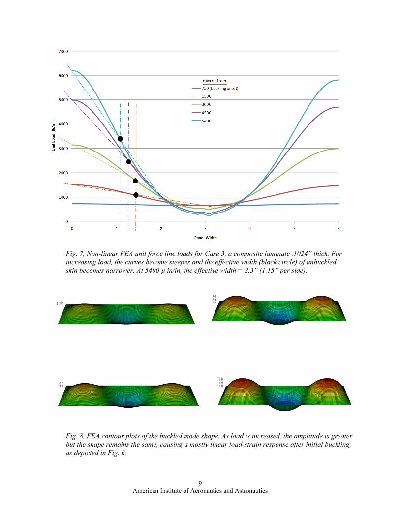
For this composite laminate, the bottom line is the collapse load of 2450 lb/in is 230 % higher than the initial buckling load of 740 lb/in. Using the conventional 1.5 ultimate load factor, this means that to take full advantage of the collapse strength, the limit load factor for local buckling would be set to .65. (1.5/2.3 = 0.65). Figs 7 and 8 show post processing results of the non-linear FEA that relate to Fig. 6. The traditionally known post buckling stress profile as depicted in Fig 4c was able to be established with the geometric non-linear FEA. Fig 7 presents the post processing results for different loading steps. Instead of reporting stress, more convenient stress resultants (unit forces) are shown on the 6” wide plate.
Fig. 6, Three different load values for Case 3, a composite laminate .1024” thick. There is close agreement between HyperSizer and the geometric non-linear FEA. 5400 µ in/in is the compressive strain limit for the composite material.
9 American Institute of Aeronautics and Astronautics
Fig. 7, Non-linear FEA unit force line loads for Case 3, a composite laminate .1024” thick. For increasing load, the curves become steeper and the effective width (black circle) of unbuckled skin becomes narrower. At 5400 µ in/in, the effective width = 2.3” (1.15” per side).
Fig. 8, FEA contour plots of the buckled mode shape. As load is increased, the amplitude is greater but the shape remains the same, causing a mostly linear load-strain response after initial buckling, as depicted in Fig. 6.

10 American Institute of Aeronautics and Astronautics
4 Classical Plate Example The stepped plate problem is related to the case where a plate is stiffened with an attached stiffener. In this case the skin is of constant thickness and does not have a flange attached. A related stiffened panel concept is the integral “blade.” The constant skin thickness example is also a good starting point for introducing the classical post buckling phenomenon.
4.1 Blodgett Example Description The local post buckling of the skin between stringers (stiffeners) behaves much like a plate simply supported on the edges. Such an example using a metallic plate is presented by Blodgett [ref]. As shown in Fig. 9a, the middle strip of the plate bows out, causing the stress to remain a constant value (Fcr) once the panel goes into a buckling bifurcation mode. Upon additional loading, the plate stress increases in the sides of the panel that are prevented by the simple (knife edge) support from bowing out. The width of this strip of plate that can continue supporting load is referred to as the “effective width, be.” Collapse failure occurs when the edge stress reaches the compressive yield stress allowable (Fcy). For a stiffened panel the skin between stiffeners, including the stepped thickness of the bonded flange, behaves like the plate analogy described above, particular if the supporting stiffener is stiff and strong. If not, the only difference is that the stiffener has additional potential failure modes that may prevent the plate skin from reaching the material Fcy. The stiffener may fail in crippling, column buckling, or in a Johnson-Euler interaction that limits the stress allowable more than compressive yield, Fcy. \
be
Fig. 9, The classical explanation of post buckling effective width.
9a
9b
9c

11 American Institute of Aeronautics and Astronautics
4.2 Classical Plate Solution Implemented for a Stiffened Panel An important concept to grasp is local buckling stability of the effective width of skin over top of the stiffener is being converged. For the initial bifurcation buckling, the span width is the full span noted as Sx, light blue color. As load is increased to some intermediate load step, the effective width becomes more narrow and is = be(i), red color. By inspection, the boundary condition of this more narrow buckling span width is difficult to comprehend. It appears as if it were some complicated combination or rotational and translational restraint. By looking at the graphic, an appropriate analysis BC would be to perform local buckling as ½ the width with the right edge constrained against rotation and the left edge as simply supported. This is the same symmetry BC often used in a FEM to get the full Sx span effect with a half model. If this is true, then the same buckling solution of the initial be(i) effective width would be obtained by using the Sx stiffener spacing with simple BC. And by definition this would prove to be correct because, at local bifurcation load, the buckling load of the initial be(i) effective width has to equal the buckling load of the skin with an Sx width and with simple BC. In summary, the proper BC of the local buckling analysis of the effective width of skin over top of the stiffener (light blue and red lines) is to use simple BC.
Fig. 10, The effective width of a panel stiffener can be analyzed using simple boundary conditions regardless of its relative width to the unbuckled span.

12 American Institute of Aeronautics and Astronautics
4.3 Traditional ‘Effective Width’ Solution The industry method for calculating effective width for the facesheet of a stiffened panel is to use eqn (2), with crippling stress of the stiffener as the reference stress (crippling stress is noted as Fcc or Fcr,st). See [2, eqn 5.5.2] and [3, eqn 14.2.1]. Reference [3, eqn 11.1.3] most commonly uses this abbreviated form of the equation
stcr
ce F
EKtb
,
= (2)
where Kc is the skin compression buckling coefficient, which accounts for simple versus fixed boundary conditions based on the skin b/t ratio [3, Fig 14.2.3].
3.0,904.0)1(12 2
2
==−
= υυ
π forkkKc (3)
Reference [9] uses a similar approach to calculating effective width and includes some terms for orthotropic stiffnesses of the materials.
stiffExcFctskinExcDD
tbe ,,
96.3 32211= (4)
For panels that have the same isotropic material for both the skin and stringer, this equation reduces to
FctDbe
1196.3= (5)
For isotropic materials, eqn (5) should produce the same result as eqn (2). However, comparing eqn (5) to eqn (2) there is a difference of 6.28/3.96 = 1.586. We assume this difference is due to a typo mistake in reference [4], which is a preliminary document. Both methods use only the stiffener cross section for computing crippling stress. Neither method attempts to include the effective width of the facesheet in the crippling solution. The method in [4] accounts for crippling-buckling Johnson Euler effects and includes the effective width in the column buckling moment of inertia/radius of gyration properties.

13 American Institute of Aeronautics and Astronautics
5 Stiffened Panel Implementation
5.1 Inner and Outer Loop Convergence, The HyperSizer specific implementation is best introduced with a flowchart, Fig. 11. Here we see how local post buckling is incorporated into the program logic. Note that there are two major convergences. The first convergence is noted with the blue dashed box and is for the effective width. This convergence is performed on an inner program data flow level, while the second convergence is for the overall panel stiffness and internal load redistribution, which occurs on an outer program logic level. Inner Loop: Effective Width Convergence The process begins by performing a typical linear elastic analysis and identifying a panel object that has local buckled, such as the facesheet/skin between stiffeners. The full unit load of Nx, Ny, and Nxy in that object, per loadcase, is then used with an orthotropic mode shape minimization buckling routine to iterate on the sheet width, to cause it to be just at the point of buckling bifurcation. Once converged, this is noted as the effective width. In other words, the effective width is capable of supporting the Nx, Ny, and Nxy loads without buckling. This process is in contrast to a hand method which uses eqn (2) or (4) to directly compute the effective width. Outer Loop: Overall Panel Stiffness ConvergenceOnce the effective width of an object is determined, then the remaining stable cross section can be determined for computing new generalized stiffness matrices [A], [B], and [D], including corresponding thermal coefficients for membrane, bending, and membrane-bending coupling. These updated stiffnesses and thermal coefficients will cause an update in forces of all objects, which cause a change in the reference stress and a change in effective widths. Also additional objects might local buckle. This cycle is repeated until convergence. The local buckled objects bifurication loads are held constant for the overall panel: The Nx, Ny, and Nxy unit forces in the object at onset of local buckling are identified. These forces will remain constant as other parts of the panel are able to support more load. Note that the effective width convergence and update of stiffness is performed for any combination of loading that causes a span object to local buckle. Also note that the update stiffness for the remaining stable cross section, with its corresponding redistribution of internal loads into the unbuckled objects, is used by all analyses such as panel buckling, beam-column buckling, crippling, frequency, deformation, material strength, Therefore Free Body Diagram (FBD) force equilibrium and strain compatibility are ensured throughout the process of converging both the effective width and overall panel stiffness.

14 American Institute of Aeronautics and Astronautics
Yes
No
Yes
No
Yes
No
unloaded - linear elastic cross section
Analysis Process - Local Post Buckling
for the cross section, compute panel[A], [B], [D] matrices and neutral axes
apply panel loads at the reference plane, compute κ & ε
compute object loads
perform strength and stability analyses for panel and eachanalysis object. This includes: local buckling, crippling,
crippling -column buckling interation, material strength, etc.
test: Σ of object forces = applied panel loads
Anyobjects local
buckled?
done
identify the localbuckled object, itsbifurcation load,effective width,
and the remainingstable cross
section
do localpost
buckling?
use remainingstable cross
section
Yes
No
do localpost
buckling?
remove localbuckled object
bifurcation loads
do object localbuckling using
updatedeffective width
point ofbifurcation
?
updateeffective
width
converge effective width
converge panel stiffness
Fig. 11, The overall HyperSizer analysis method for converging the effective width and panel stiffness as the local post buckling progresses.

15 American Institute of Aeronautics and Astronautics
Fig. 12a) top image shows that the area of under the green FEA computed curve equals the area under the purple rectangular sections. Fig 12b) portrays this same point by identifying that the area of the top triangle equals the area of the bottom triangle. The bottom figure also illustrates how upon higher loading the effective width becomes more narrow (black circles).

16 American Institute of Aeronautics and Astronautics
By implementing the iterative process outlined in the flowchart of Fig. 11, the results of Fig 12a and 12b are possible. By iterating to a converged effective width for every load case, the area under the rectangle defined by the material stress limit and effective width as implemented in HyperSizer will equal to the the area under the FEA computed unit force (stress resultant).
6 Five Verification Cases Example Dimensions and Materials The following verification cases use dimensions that represent those typical of stiffened panels, in particular, the width and length of the skin between stiffeners. A 6” width is used to represent the skin spanning the stiffeners. A 20” length is used to represent the distance between ringframes. The boundary conditions are also typical for a stiffened panel and are simple on all four edges. Loading is uniaxial compression with the transverse edge free to displace. Three different materials and three different thicknesses are used. Each result figure title lists the material and thickness. Below are the material properties.
Initial Buckling As reported in Figs. 13-18 buckling prediction using linear eigenvalue analysis is nearly the same. Both the analytical method and FEA predict the same eigenvalue. Note that the load – displacement plot is perfectly linear up to local buckling. Post Local Buckling After local buckling, the load – displacement plot is non-linear. As shown in Figs. 13 - 18, both the analytical method (HyperSizer) and Abaqus FEA predict the same slope well past the bifurcation point. The difference being that the analytical method shows a more gradual transition .
Materials E1 E2 G nu Yield (ksi) Ultimate (ksi) Strain Allow (microstrain)Simple Aluminum 10 10 3.759398 0.33 64 64 N/AComposite (Ply) 16.43 1.6 0.8 0.34 N/A N/A 5400Al 7075 10.5 10.5 3.9474 0.33 71 71 N/A
[45/‐45/0/90/0/‐45/45/45/‐45/0/90/0/‐45/45]Ex Ey G nu
Composite Layup 9.278658 4.719836 2.300681 0.399284
17 American Institute of Aeronautics and Astronautics
6.1 Case 1: Thin metallic skin
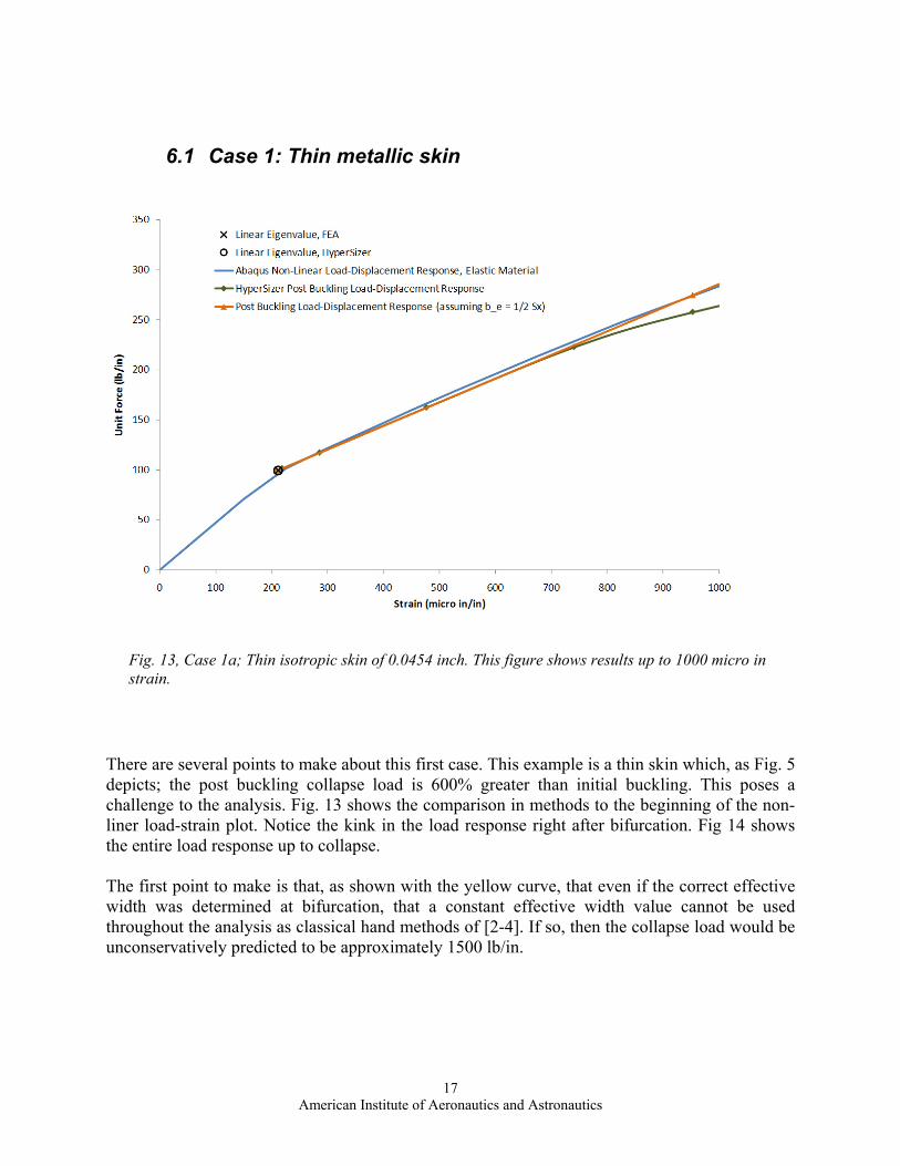
There are several points to make about this first case. This example is a thin skin which, as Fig. 5 depicts; the post buckling collapse load is 600% greater than initial buckling. This poses a challenge to the analysis. Fig. 13 shows the comparison in methods to the beginning of the non-liner load-strain plot. Notice the kink in the load response right after bifurcation. Fig 14 shows the entire load response up to collapse. The first point to make is that, as shown with the yellow curve, that even if the correct effective width was determined at bifurcation, that a constant effective width value cannot be used throughout the analysis as classical hand methods of [2-4]. If so, then the collapse load would be unconservatively predicted to be approximately 1500 lb/in.
Fig. 13, Case 1a; Thin isotropic skin of 0.0454 inch. This figure shows results up to 1000 micro in strain.

18 American Institute of Aeronautics and Astronautics
The second point to make is that FEA non-linear solutions have difficulty in obtaining the lowest mode once a mode shape is started. In this case the initial buckling mode was three half waves. However, the FEA solution was not able to capture the lower buckling modes of half waves of 4 through 7 and took a dramatic jump in drop in load capability as it transition from the 3 to 8 modes. It is plausible that as the load was increased to near collapse load, the FEA again missed the lowest mode. The third point to make is that due to the thinness of the plate, material plasticity was insignificant.
Fig. 14, Case 1a; Thin isotropic skin of 0.0454 inch. This figure shows results up to 6800 micro in strain.

19 American Institute of Aeronautics and Astronautics
6.2 Case 2: Typical metallic skin thickness
Fig. 15, Case 2a; Isotropic thickness of 0.1024 inch. Both approaches predict the same response after initial buckling.
20 American Institute of Aeronautics and Astronautics
6.3 Case 3: Typical composite laminate thickness
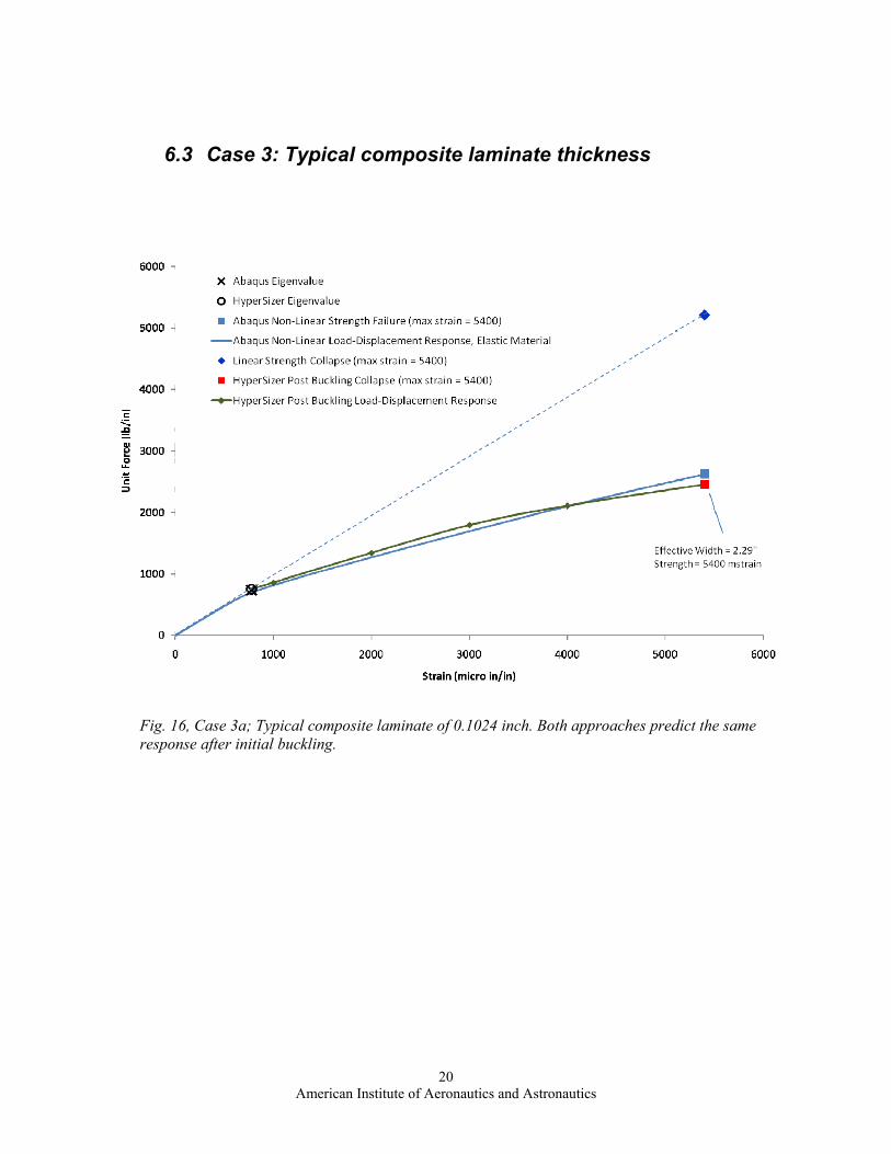
Fig. 16, Case 3a; Typical composite laminate of 0.1024 inch. Both approaches predict the same response after initial buckling.

21 American Institute of Aeronautics and Astronautics
6.4 Case 4: Thick metallic skin
Material plasticity becomes an issue with plates that are relatively thick in comparison to their span widths. The Fcu and Fcy, ultimate and yield stress allowable of the material was used.
Fig. 17, Case 4a; Thick metal skin of 0.1624 inch. HyperSizer and Abaqus match very well. At point F, the material exhibits material non-linearity and the plate is no longer capable of carrying additional load.

22 American Institute of Aeronautics and Astronautics
6.5 Case 5: Thick composite laminate
Fig. 18, Case 5a; Thick composite laminate of 0.1624 inch. The onset of initial buckling is not as well defined with both eigenvalue solutions being slightly higher than the non-linear response. However, both analysis approaches predict a linear response after initial buckling.

23 American Institute of Aeronautics and Astronautics
7 Acknowledgments This material is based upon work fully funded by internal Collier Research Corporation funding.
8 References
1. Collier, C.S., Yarrington, P.W., Van West, B. “Composite, Grid-Stiffened Panel Design for Post Buckling Using HyperSizer", AIAA/ASME/ASCE/AHS/ASC Structures, Structural Dynamics, and Materials Conference, Denver, CO, April 2002, AIAA-2002-1222.
2. Niu, Michael C. Y., Airframe Structural Design, 1988, Conmilit Press LTD, ISBN 962-7128-04-X
3. Niu, Michael C. Y., Airframe Stress Analysis and Sizing, 1997,Conmilit Press LTD, ISBN 962-7128-07-4
4. HSR, High-Speed Research Program Preliminary Analysis/Sizing Handbook for Fuselage Structures, Revision B, 30 Sept 98, pp 30-32
5. Heitmann, M. and Horst, P., “A New Analysis Model for the Effective Stiffness of Stiffened Metallic
Panels Under Combined Compression and Shear Stress”, Elsevier Aerospace Science and Technology 10, pp 316-326, 2006
6. Von Karman, Tl, Sechler, E. E., and Donnell, L. H., “The Strength of Thin Plates in Compression,” ASME
Transactions, APM-54-5, Vol. 54, No. 2, 30 Jan 1932, pp. 53-57
7. Hilburger, M. W., Nemeth, M. P., and Starnes, Jr., J. H., “Effective Widths of Compression-Loaded Plates with a Cutout”, NASA TP-2000-210538, Oct 2000.
TRADEMARKS HyperSizer® is a registered trademark of Collier Research Corporation
Abaqus® is a registered trademark of Simulia