local government public works …and...division 31: earthwork..... 75 31 11 00 clearing and grubbing...
TRANSCRIPT

LOCAL GOVERNMENTPUBLIC WORKS STANDARDS
and SPECIFICATIONSGuidelines for construction standards,
materials specifications, design criteria, andcontract documents to be used for streets,
storm sewers, sanitary sewers,and water distribution systems
John Chlarson, P.E., and Sharon Rollins, P.E.Public Works and Engineering Consultants
In cooperation with the Tennessee Municipal League

This document is designed to aid in the development of standards for construction specifications and in the design and bidding of public works improvements and should not be used in lieu thereof.

LOCAL GOVERNMENT PUBLIC WORKS STANDARDS AND SPECIFICATIONSGuidelines for construction standards,materials specifications, design criteria, and contract documents to be used for streets, storm sewers, sanitary sewers, and water distribution systems
John Chlarson, P.E., and Sharon Rollins, P.E.Public Works and Engineering Consultants
The Municipal Technical Advisory Service (MTAS) was created in 1949 by the state legislature to enhance the quality of government in Tennessee municipalities. An agency of the University of Tennessee Institute for Public Service, MTAS works in cooperation with the Tennessee Municipal League and affiliated organizations to assist municipal officials.
By sharing information, responding to client requests,and anticipating the ever-changing municipal government environment, MTAS promotes better local governmentand helps cities develop and sustain effective management and leadership.
MTAS offers assistance in areas such as accounting and finance, administration and personnel, fire, public works, law, ordinance codification, and water and wastewater
management. MTAS houses a comprehensive library and publishes scores of documents annually.
MTAS provides one copy of our publications free of charge to each Tennessee municipality, county and department of state and federal government. There is a $50 charge for additional copies of “Local Government Public Works Standards and Specifications.”
Photocopying of this publication in small quantities for educational purposes is encouraged. For permission to copy and distribute large quantities, please contact the MTAS Knoxville office at (865) 974-0411.
MTAS OFFICESKnoxville (Headquarters) ....................... (865) 974-0411Chattanooga ........................................ (423) 643-0849Johnson City ......................................... (423) 854-9882Nashville .................................................(615) 532-6827Jackson ................................................... (731) 423-3710Martin ....................................................(731) 881-7055Memphis ................................................ (901) 412-2121
www.mtas.tennessee.edu


INTRODUCTION
LOCAL GOVERNMENT PUBLIC WORKS STANDARDS AND SPECIFICATIONS • MUNICIPAL TECHNICAL ADVISORY SERVICE i
Local Government Public Works Standards and Specifications was developed to provide Tennessee cities with guidelines for construction projects. MTAS recommends, and T.C.A. § 62-2-107 requires, that public works projects over $50,000 have plans and specifications prepared by a registered architect, engineer, or landscape architect. Therefore, users should be careful in adopting and using these guidelines. They are not intended to be all-inclusive. The construction standards and specifications presented here are not minimum standards. They are based on recognized engineering practices, and they are intended to produce quality projects.
Recommended uses of Local Government Public Works Standards and Specifications:• To provide basic construction standards for public works and utility projects.• To serve as a reference for city engineers, public works directors, and the city’s engineering
consultants.• To serve as a review guide for planning commissions and as a technical guide for local government
engineering departments. Use of this document will simplify the review process and assure uniformity in public improvement projects.
• To provide links to technical references and state agencies.• Other References: This document is organized in accordance with the Construction Specifications
Institute (CSI) index.• This document references The Tennessee Department of Economic and Community Development
(TDECD), Community Development Block Grant (CBDG) Contract documents (such as Invitation to Bidders, Bid Form, Bid Bond, Performance Bond, Agreement, General Conditions, Supplementary Conditions, etc). Contract documents for projects funded by TDECD are referenced herein and these documents can be found on the TDECD http://www.tn.gov/ecd/CDBG/Handbook.shtml, Labor Chapter.
• This document references Tennessee Department of Environment and Conservation design criteria for water and wastewater. Latest versions of these criteria may be found at TDEC’s website: http://www.state.tn.us/environment.
• This document references Tennessee Department of Transportation (TDOT) standard specifications and drawings. Latest versions of TDOT documents may be found at TDOT’s website: http://www.tdot.state.tn.us.
• This document references the Tennessee Ready Mix Concrete Association.
ACKNOWLEDGMENTSMTAS thanks the following agencies for allowing us to reference and use their documents and for the reviews and comments of their staff in the preparation of this update to Local Government Public Works Standards and Specifications: Tennessee Department of Economic and Community Development Tennessee Department of Environment and Conservation Tennessee Ready Mix Concrete Association Tennessee Department of Transportation

TABLE OF CONTENTS
LOCAL GOVERNMENT PUBLIC WORKS STANDARDS AND SPECIFICATIONS • MUNICIPAL TECHNICAL ADVISORY SERVICE
CONTRACT DOCUMENTSDivision 00: Procurement and Contracting Requirements ......................................1
MTAS recommends the user refer to Tennessee Department of Economic and Community Development Contract Documents 2006 CBDG Handbook (or most recent version), Labor Chapter. See the following website: http://www.tn.gov/ecd/CDBG/Handbook.shtml
CONSTRUCTION STANDARDS AND SPECIFICATIONSDivision 01: General Requirements ........................................3 01 11 10 Summary of Work..................................................3 01 26 00 Contract Modification Procedures ............................401 26 57 Change Order Procedures .......................................6 01 29 00 Payment Procedures ..............................................9 01 29 73 Schedule of Values .............................................. 10 01 32 26 Construction Progress Reporting ........................... 1101 32 33 Photographic Documentation ............................... 1301 33 23 Shop Drawings, Product Data, and Samples ............ 1401 35 53 Security Procedures ............................................ 16 01 42 13 References ......................................................... 17 01 51 00 Temporary Utilities ............................................. 20 01 52 13 Field Offices and Sheds ........................................ 21 01 54 00 Construction Aids ............................................... 23 01 55 26 Traffic Control .................................................... 24 01 56 00 Temporary Barriers and Enclosures ........................ 2501 57 00 Temporary Controls ............................................. 26 01 58 00 Project Identification .......................................... 30 01 60 00 Product Requirements ......................................... 32 01 74 00 Cleaning and Waste Management .......................... 3401 77 00 Closeout Procedures ............................................ 35 01 78 39 Project Record Documents ................................... 38
Division 02: Existing Conditions ........................................... 39 02 41 00 Demolition ........................................................ 39
Division 03: Concrete .......................................................... 4103 00 00 Concrete ........................................................... 4103 30 00 Cast in Place Concrete ......................................... 52 Division 26: Electrical ......................................................... 71 26 56 19 Highway Lighting ............................................... 71
Division 31: Earthwork ........................................................ 7531 11 00 Clearing and Grubbing ......................................... 75 31 20 00 Earth Moving ..................................................... 7631 23 00 Excavation and Fill ............................................. 79 31 37 00 Riprap .............................................................. 84 Division 32: Exterior Improvements ................................... 89
32 11 00 Base Courses ..................................................... 89 32 12 00 Flexible Paving ................................................... 97 32 12 43 Porous Flexible Paving ....................................... 110 32 13 00 Rigid Paving .................................................... 112 32 17 23 Pavement Marking ............................................ 121 32 31 00 Chain Link Fences and Gates .............................. 12332 90 00 Planting .......................................................... 124
Division 33: Utilities ............................................................. 129 33 05 23 Trenchless Utility Installation ............................. 12933 10 00 Water Utility Distribution Piping ......................... 13933 11 13 Separation of Piped Utilities .............................. 14733 30 00 Sanitary Sewerage Utilities ................................ 14833 40 00 Storm Drainage Utilities .................................... 157 DESIGN CRITERIA .................................................................... 163Water Distribution SystemsScope .................................................................................... 163Engineer’s Report ..................................................................... 163Design Factors ......................................................................... 163Selection of Pressure Class for Water Mains .................................. 164Location of Appurtenances ........................................................ 165Installation and Acceptance Testing ........................................... 165Preparation of Plans—Water Distribution System .......................... 166Water Distribution System—Standard Drawings: Thrust Blocking Details TBD 1 ............................. 167 Thrust Blocking Dimensions TBD 2 ............................. 168 Gate Valve and Valve Box GV-VB 1.......................... 169 Fire Hydrant Assembly FHA 1 ............................ 170 Blowoff Hydrant Assembly BHA 1 ............................ 171 Air Release Valve Assembly AR-VA 1 .......................... 172 Water Service Assembly 5/8” x 3/4” Meter WSA 1 ............................ 173 Water Service Assembly 2” Meter WSA 2 ............................ 174
Wastewater SystemsScope .................................................................................... 175Engineer’s Report ..................................................................... 175Planning Factors ...................................................................... 175Details of Design and Construction—Gravity Mains ....................... 176Manholes ................................................................................ 178Installation and Acceptance Testing ........................................... 179Protection of Water Supplies ..................................................... 179Preparation of Plans—Sanitary Sewer Facilities ............................ 181Wastewater System—Standard Drawings ..................................... 182 Traffic & Non-Traffic Manhole Frame and Cover MH-FC 1 ......................... 183 Watertight Manhole Frame and Cover MH-FC 2 ......................... 184 Standard Precast Concrete Manhole MH-PC 1 ......................... 185 Shallow Precast Concrete Manhole MH-PC 2 ......................... 186

LOCAL GOVERNMENT PUBLIC WORKS STANDARDS AND SPECIFICATIONS • MUNICIPAL TECHNICAL ADVISORY SERVICE
Offset Precast Concrete Manhole MH-PC 3 ......................... 187 Drop Manhole MH-D 1 .......................... 188 Sewer Service Connection SSC 1 ............................. 189 Sewer Cleanout SC 1 ............................... 190 Pavement Replacement Backfill PR-B 1 ........................... 191 Pavement Replacement Backfill PR-B 2 ........................... 192 Backfill B 1 ................................ 193
Drainage SystemsScope .................................................................................... 195General .................................................................................. 195Design Procedures .................................................................... 196Runoff Calculation and Criteria .................................................. 197Pipe Sizing ............................................................................. 197Location ................................................................................. 198Depth of Cover ........................................................................ 198Drainage Inlets ........................................................................ 199Open Channels ........................................................................ 199Design Details ......................................................................... 200Easements .............................................................................. 200Suggested Storm Sewer Design - Checklist ................................... 201Temporary Detention ................................................................ 201Methods to Reduce Quantity of Runoff and Minimize Pollution ....... 202Drainage System—Standard Drawings & Design Charts Rainfall Intensity Frequency— Duration Curves RIFDC-1 .......................... 205 Rainfall Intensity Frequency— Duration Curves RIFDC-2 .......................... 206 Rainfall Intensity Frequency— Duration Curves RIFDC-3 .......................... 207 Rainfall Intensity Frequency— Duration Curves RIFDC-4 .......................... 208 Critical Depth Circular Pipe CDCP-1 ........................... 209 Critical Depth Rectangular Section CDRS-1 ........................... 210 Head for Standard Corrugated Metal Pipe Culverts Flowing Full HSCMPC-1 ....................... 211 Head for Standard Corrugated Metal Pipe Arch Culverts Flowing Full HSCMPAC-1 ..................... 212 Head for Structural Plate Corrugated Metal Pipe Culverts Flowing Full HSPCMP-1 ....................... 213 Head for Standard Corrugated Metal Pipe Arch Culverts 18” Corner Radius Flowing Full HSPCMPAC-1.................... 214 Headwater Depth for Box Culverts w/ Inlet Control HWDBC-1 ........................ 215 Headwater Depth for Concrete Pipe Culverts w/ Inlet Control HWDCPC-1 ...................... 216 Headwater Depth for Circular Pipe Culverts w/Beveled Ring Inlet Control HWDCPC-BR-1 ................. 217 Headwater Depth for Corrugated Metal Pipe Culverts w/Inlet Control HWDCMPC-1 .................... 218 Culvert Installation Details CI-1 ............................... 219 Precast Catch Basin PCB-1 ............................ 220 Field Basin with Side Opening FB-1 .............................. 221
Field Basin with Grate FB-2 .............................. 222 Culvert Headwall Details CH-1 .............................. 223 Culvert Headwall Details CH-2 .............................. 224 Culvert Headwall Details CH-3 .............................. 225 Single and Combination Curb Inlets SCCI-1 ............................ 226 Brush Barrier BB-1 .............................. 227 Sediment Trap Details ST-1 ............................... 228 Sediment Pond Details SP-1 .............................. 229 Temporary Slope Drain TSD-1 ............................. 230 Temporary Slope Drain TSD-2 ............................. 231 Log & Pole Check Dam LPCD-1 ........................... 232
StreetsUser is also referred to TDOT’s website: www.tdot.statetn.us/Scope .................................................................................... 233General .................................................................................. 233Design Elements ...................................................................... 233Pavement Crown ...................................................................... 235Number of Lanes ...................................................................... 236Roadway Widths ...................................................................... 236Median ................................................................................... 236Curbs, Gutters and Sidewalks ..................................................... 236Traffic Calming ........................................................................ 236Driveways ............................................................................... 237Bridge Width ........................................................................... 237Lateral Clearance ..................................................................... 237Right-of-way Width .................................................................. 238Accommodation of Utilities ....................................................... 238Railroad Grade Crossing ............................................................ 238Street Lighting ........................................................................ 238Traffic Control Devices .............................................................. 238Erosion Control ..................................................................... 238Pavement Design ..................................................................... 238Preparation of Plans ................................................................. 239 Street—Standard Drawings..................................................... 240

LOCAL GOVERNMENT PUBLIC WORKS STANDARDS AND SPECIFICATIONS • MUNICIPAL TECHNICAL ADVISORY SERVICE 1
DIVISION 00PROCUREMENT AND
CONTRACTING REQUIREMENTSMTAS recommends that the user refer to Tennessee Department of Economic and Community Development CBDG Handbook, Labor Chapter.
See the following website: http://www.tn.gov/ecd/CDBG/Handbook.shtml

2 LOCAL GOVERNMENT PUBLIC WORKS STANDARDS AND SPECIFICATIONS • MUNICIPAL TECHNICAL ADVISORY SERVICE
LOCAL GOVERNMENT PUBLIC WORKS STANDARDS AND SPECIFICATIONS • MUNICIPAL TECHNICAL ADVISORY SERVICE 3
SECTION 01 11 00SUMMARY OF WORKPART 1–GENERAL1.01 WORK COVERED BY CONTRACT DOCUMENTS REQUIREMENTS INCLUDED A. The Work of this Contract comprises the general construction of __________________________ ______________________________________________________________________________ ______________________________________________________________________________ located __________________________ for _________________________________________.
1.02 RELATED REQUIREMENTS General and Supplementary Conditions.
1.03 CONTRACTS Construct the Work under a single unit-price or lump-sum contract, as shown on the Bid Form.
1.04 WORK BY OTHERS A. Work on the Project, which will be executed prior to the start of Work of this Contract and which is excluded from this Contract, if any, as follows: 1. ______________________________________________________________________________ 2. ______________________________________________________________________________ 3. ______________________________________________________________________________ B. Work on the Project, which will be executed after completion of the Work of this Contract and which is excluded from this contract, if any, as follows: 1. ______________________________________________________________________________ 2. ______________________________________________________________________________ 3. ______________________________________________________________________________
1.05 FUTURE WORK A. The project is designed for future, if any. ______________________________________________________________________________ ______________________________________________________________________________ B. Insure that Work is clear of encroachment into areas required for future work, if any. C. ______________________________________________________________________________ ______________________________________________________________________________ 1.06 WORK SEQUENCE A. Construct the Work in stages to accommodate the Owner’s use of the the premises during the construction period; coordinate the construction schedule and operations with the Owner’s Representative.
DIVISION 01GENERAL REQUIREMENTS

4 LOCAL GOVERNMENT PUBLIC WORKS STANDARDS AND SPECIFICATIONS • MUNICIPAL TECHNICAL ADVISORY SERVICE
B. Construct the Work in stages to provide for public convenience. 1. Do not close off public use of facilities until completion of one stage of construction will provide alternative usage. 2. Stages of construction are those indicated on drawings.
1.07 CONTRACTOR’S USE OF PREMISES A. Contractor shall limit his use of the premises for Work and for storage, to allow for 1. Work by other Contractors. 2. Owner occupancy. 3. Public use. B. Coordinate use of premises under direction of Owner’s representative. C. Assume full responsibility for the protection and safekeeping of Products under this Contract that are stored on the site. D. Move any stored Products under Contractor’s control that interfere with operations of the Owner or separate contractor. E. Obtain and pay for the use of additional storage or work areas needed for operations.
PART 2—PRODUCTS(Not Used)
PART 3—EXECUTION A. Attention to Work—Contractor shall give personal attention to and shall supervise the Work to the end that it shall be prosecuted faithfully. When he/she is not personally on site, a competent superintendent or foreman who shall be the legal representative of the Contractor shall represent him. B. Access to Work—The Contractor shall provide access for inspection of the Work by the Owner and or official Governmental agencies. C. Job Site Meetings—(specify to meet project requirements). D. Contract Working Hours—(specify to meet projects requirements).
SECTION 01 26 00CONTRACT MODIFICATION PROCEDURESPART 1—GENERAL1.01 REQUIREMENTS INCLUDED A. Contractor shall be responsible for all cutting, fitting, and patching, including attendant excavation and backfill, required to complete the Work or to 1. Make its several parts fit together properly. 2. Uncover portions of the Work to provide for installation and ill-timed work. 3. Remove and replace defective work. 4. Remove and replace Work not conforming to requirements of Contract Documents. 5. Remove samples of installed Work as specified for testing. 6. Provide routine penetrations of nonstructural surfaces for installation of piping and electrical conduit.
1.02 RELATED DOCUMENTS A. Section 01 11 10: Summary of Work. B. Section 31 20 00: Earth Moving.

LOCAL GOVERNMENT PUBLIC WORKS STANDARDS AND SPECIFICATIONS • MUNICIPAL TECHNICAL ADVISORY SERVICE 5
1.03 SUBMITTALS A. Submit a written request to Engineer well in advance of executing any cutting or alteration that affects 1. Work of the Owner or any separate contractor. 2. Structural value or integrity of any element of the Project. 3. Integrity or effectiveness of weather exposed or moisture-resistant elements or systems. 4. Efficiency, operational life, maintenance, or safety of operational elements. 5. Visual qualities of sight-exposed elements. B. Request shall include 1. Identification of the Project. 2. Description of affected Work. 3. Necessity for cutting, alteration, or excavation. 4. Effect on Work of Owner or any separate contractor, or on structural or weatherproof integrity of Project. 5. Description of proposed Work: a. Scope of cutting, patching, alteration, or excavation. b. Trades who will execute the work. c. Products proposed to be used. d. Extent of refinishing to be done. 6. Alternatives to cutting and patching. 7. Cost proposal, when applicable. 8. Written permission of any separate contractor whose work will be affected. C. Should conditions of Work or the schedule indicate a change of products from original installation, Contractor shall submit request for substitution. D. Submit written notice to Engineer designating the date and the time the work will be uncovered.
PART 2—PRODUCTS2.01 MATERIALS Comply with specifications and standards for each specific product involved.
PART 3—EXECUTION3.01 INSPECTIONS A. Inspect existing conditions of Project, including elements subject to damage or to movement during cutting and patching. B. After uncovering work, inspect conditions affecting installation of products or performance of Work. C. Report unsatisfactory or questionable conditions to Engineer in writing; do not proceed with work until Engineer has provided further instructions.
3.02 PREPARATION A. Provide adequate temporary support as necessary to assure structural value or integrity of affected portion of Work. B. Provide devices and methods to protect other portions of Project from damage. C. Provide protection from elements for that portion of the Project that may be exposed by cutting and patching work, and maintain excavations free from water.

6 LOCAL GOVERNMENT PUBLIC WORKS STANDARDS AND SPECIFICATIONS • MUNICIPAL TECHNICAL ADVISORY SERVICE
3.03 PERFORMANCE A. Execute cutting and demolition by methods that will prevent damage to other work and will provide proper surfaces to receive installation of repairs. B. Execute excavating and backfilling by methods that will prevent settlement or damage to other work. C. Employ original Installer or Fabricator to perform cutting and patching for 1. Weather-exposed or moisture resistant elements. 2. Sight-exposed finished surfaces. D. Execute fitting and adjustment of products to provide a finished installation to comply with specified products, functions, tolerances, and finishes. E. Restore work that has been cut or removed; install new products to provide completed Work in accordance with requirements of Contract Documents. F. Fit Work airtight to pipes, sleeves, ducts, conduit, and other penetrations through the surfaces. G. Refinish entire surfaces as necessary to provide an even finish to match adjacent finishes 1. For continuous surfaces, refinish to nearest intersection. 2. For an assembly, refinish entire unit.
SECTION 01 26 57CHANGE ORDER PROCEDURESPART 1—GENERAL1.01 REQUIREMENTS INCLUDED A. Promptly implement Change Order procedures. 1. Provide full written data required to evaluate changes. 2. Maintain detailed records of work done on a time-and-material/force account basis. 3. Provide full documentation to Engineer on request. B. Designate in writing the member of Contractor’s organization: 1. Who is authorized to accept changes in the Work. 2. Who is responsible for informing others in the Contractor’s employ of the authorization of changes in the Work. C. Owner will designate in writing the person who is authorized to execute Change Orders.
1.02 RELATED REQUIREMENTS A. Agreement: The amounts of established unit prices. B. Conditions of the Contract: 1. Methods of determining cost or credit to Owner resulting from changes in Work made on a time and material basis. 2. Contractor’s claims for additional costs. C. Section 01 29 00: Payment Procedures. D. Section 01 78 39: Project Record Documents.
1.03 DEFINITIONS A. Change Order: See General Conditions. B. Engineer’s Supplemental Instructions: A written order, instructions, or interpretations, signed by Engineer making minor changes in the Work not involving a change in Contract Sum or Contract Time.

LOCAL GOVERNMENT PUBLIC WORKS STANDARDS AND SPECIFICATIONS • MUNICIPAL TECHNICAL ADVISORY SERVICE 7
1.04 PRELIMINARY PROCEDURES A. Owner or Engineer may initiate changes by submitting a Proposal Request to Contractor. Request will include 1. Detailed description of the Change, Products, and location of the change in the Project. 2. Supplementary or revised Drawings and Specifications. 3. The projected time span for making the change and a specific statement as to whether overtime work is, or is not, authorized. 4. A specific period of time during which the requested price will be considered valid. 5. Such request is for information only and is not an instruction to execute the changes or to stop Work in progress. B. Contractor may initiate changes by submitting a written notice to Engineer containing 1. Description of the proposed changes. 2. Statement of the reason for making the changes. 3. Statement of the effect on the Contract Sum and the Contract Time. 4. Statement of the effect of the work of separate contractors. 5. Documentation supporting any change in Contract Sum or Contract Time, as appropriate.
1.05 DOCUMENTATION OF PROPOSALS AND CLAIMS A. Support each quotation for a lump sum proposal and for each unit price that has not previously been established with sufficient substantiating data to allow Engineer to evaluate the quotation. B. On request, provide additional data to support time and cost computations 1. Labor required. 2. Equipment required. 3. Products required. a. Recommended source of purchase and unit cost. b. Quantities required. 4. Taxes, insurance, and bonds. 5. Credit for work deleted from Contract, similarly documented. 6. Overhead and profit. 7. Justification for any change in Contract Time. C. Support each claim for additional costs and for work done on a time and material/force account basis with documentation as required for a lump-sum proposal, plus additional information. 1. Name of the Owner’s authorized agent who ordered the work and date of the order. 2. Dates and times work was performed and by whom. 3. Time record, summary of hours worked, and hourly rates paid. 4. Receipts and invoices for a. Equipment used, listing dates and times of use. b. Products used with list of quantities. c. Subcontracts.
1.06 PREPARATION OF CHANGE ORDERS A. Engineer will prepare each Change Order. B. Form: Change Order: Engineers Joint Contract Documents Committee (ECJDC) Document C-941. C. Change Order will describe changes in the Work, both additions and deletions, with attachments of revised Contract Documents to define details of the change. D. Change Order will provide an accounting of the adjustment in the Contract Sum and in the Contract Time.

8 LOCAL GOVERNMENT PUBLIC WORKS STANDARDS AND SPECIFICATIONS • MUNICIPAL TECHNICAL ADVISORY SERVICE
1.07 LUMP SUM/FIXED PRICE CHANGE ORDER A. Content of Change Orders will be based on either 1. Engineer’s Proposal Request and Contractor’s responsive Proposal as mutually agreed between Owner and Contractor. 2. Contractor’s Proposal for a change, as recommended by Engineer. B. Owner and Engineer will sign and date the Change Order as authorization for the Contractor to proceed with the changes. C. Contractor may sign and date the Change Order to indicate agreement with the terms therein.
1.08 UNIT PRICE CHANGE ORDER A. Content of Change Orders will be based on either 1. Engineer’s definition of the scope of the required changes. 2. Contractor’s Proposal for a change, as recommended by Engineer. 3. Survey of completed work. B. The amounts of the unit prices to be 1. Those stated in the Agreement. 2. Those mutually agreed upon between Owner and Contractor. C. When quantities of each of the items affected by the Change Order can be determined prior to start of the work 1. Owner and Engineer will sign and date the Change Order as authorization for Contractor to proceed with the changes. 2. Contractor may sign and date the Change Order to indicate agreement with the terms therein. D. When quantities of the items cannot be determined prior to start of the work 1. Engineer or Owner will issue a construction change authorization directing Contractor to proceed with the change on the basis of unit prices, and will cite the applicable unit prices. 2. At completion of the change, Engineer will determine the cost of such work based on the unit prices and quantities used. a. Contractor shall submit documentation to establish the number of units of each item and any claims for a change in Contract Time. 3. Engineer will sign and date the Change Order to indicate his/her agreement with the terms therein. 4. Owner and Contractor will sign and date the Change Order to indicate their agreement with the terms therein.
1.09 CORRELATION WITH CONTRACTOR’S SUBMITTALS A. Periodically revise Request for Payment forms to record each change as a separate item of Work and to record the adjusted Contract Sum. B. Periodically revise the Construction Schedule to reflect each change in Contract Time. C. Upon completion of work under a Change Order, enter pertinent changes in Record Documents.
PART 2—PRODUCTS(Not Used)
PART 3—EXECUTION(Not Used)

LOCAL GOVERNMENT PUBLIC WORKS STANDARDS AND SPECIFICATIONS • MUNICIPAL TECHNICAL ADVISORY SERVICE 9
SECTION 01 29 00PAYMENT PROCEDURESPART 1—GENERAL1.01 REQUIREMENTS INCLUDED Submit Application for Payment to Engineer in accord with the schedule established by Conditions of the Contract and Agreement Between Owner and Contractor.
1.02 RELATED REQUIREMENTS A. Agreement Between Owner and Contractor: Lump Sum and Unit Prices. B. Conditions of the Contract: Progress Payments, Retainages, and Final Payment. C. Section 01 29 73: Schedule of Values. D. Section 01 77 00: Closeout Procedures.
1.03 FORMAT AND DATA REQUIRED A. Submit applications typed on EJCDC Document C-620, Contractor’s Application for Payment, with itemized data typed on 8-1/2 x 11” white paper continuation sheets. B. Provide itemized data on continuation sheet 1. Format, schedules, line items, and values: Those of the Schedule of Values accepted by Engineer.
1.04 PREPARATION OF APPLICATION FOR EACH PROGRESS PAYMENT A. Application Form 1. Fill in required information, including that for Change Orders executed prior to date of submittal of application. 2. Fill in summary of dollar values to agree with respective totals indicated on continuation sheets. 3. Execute certification with signature of a responsible officer of Contract firm. B. Continuation Sheets 1. Fill in total list of all scheduled component items of Work, with item number and scheduled dollar value for each item. 2. Fill in dollar value in each column for each scheduled line item when work has been performed or products stored. a. Round off values to nearest dollar, or as specified for Schedule of Values. 3. List each Change Order executed prior to date of submission at the end of the continuation sheets. a. List by Change Order Number and description, as for an original component item of work.
1.05 SUBSTANTIATING DATA FOR PROGRESS PAYMENTS A. When the Owner or the Engineer requires substantiating data, Contractor shall submit suitable information with a cover letter identifying 1. Project. 2. Application number and date. 3. Detailed list of enclosures. 4. For stored products a. Item number and identification as shown on application. b. Description of specific material. B. Submit one copy of data and cover letter for each copy of application.

10 LOCAL GOVERNMENT PUBLIC WORKS STANDARDS AND SPECIFICATIONS • MUNICIPAL TECHNICAL ADVISORY SERVICE
1.06 PREPARATION OF APPLICATION FOR FINAL PAYMENT A. Fill in Application form as specified for progress payments. B. Use continuation sheet to present the final statement of accounting as specified in Section 01 77 00–Contract Closeout.
1.07 SUBMITTAL PROCEDURE A. Submit Application for Payment to Engineer at the times stipulated in the Agreement. B. Number: Five copies of each Application. C. When Engineer finds Application properly completed and correct, he will transmit certificate for payment to Owner with copy to Contractor.
PART 2—PRODUCTS(Not Used)
PART 3—EXECUTION(Not Used)
SECTION 01 29 73SCHEDULE OF VALUESPART 1—GENERAL1.01 REQUIREMENTS INCLUDED A. Submit to the Engineer a Schedule of Values allocated to the various portions of the Work within 10 days after award of contract for lump sum contracts only. B. Upon request of Engineer, support the values with data that will substantiate their correctness. C. The Schedule of Values, unless objected to by the Engineer, shall be used only as the basis for the Contractor’s Applications for Payment for lump sum contracts only.
1.02 RELATED REQUIREMENTS A. Conditions of the Contract. B. Section 01 29 00: Payment Procedures.
1.03 FORM AND CONTENT OF SCHEDULE OF VALUES A. Type schedule on 8-1/2 x 11” white paper. Engineer will consider contractor’s standard forms and automated printout for approval upon Contractor’s request. Identify schedule with 1. Title of Project and location. 2. Engineer and Project number. 3. Name and address of Contractor. 4. Contract designation. 5. Date of submission. B. Schedule shall list the installed value of the component parts of the Work in sufficient detail to serve as a basis for computing values for progress payments during construction. C. Follow the table of contents of this Project Manual as the format for listing component items. 1. Identify each line item with the number and title of the respective major section of the specifications. D. For each major line item, list sub values of major products or operations under the item.

LOCAL GOVERNMENT PUBLIC WORKS STANDARDS AND SPECIFICATIONS • MUNICIPAL TECHNICAL ADVISORY SERVICE 11
E. For the various portions of the Work 1. Each item shall include a directly proportional amount of the Contractor’s overhead and profit. 2. For items on which progress payments will be requested for stored materials, break down the value into a. The cost of the materials, delivered and unloaded, with taxes paid. b. The total installed value. 3. Submit a subschedule for each separate stage of work specified in Section 01 11 00. F. The sum of all values listed in the schedule shall equal the total Contract Sum.
1.04 SUBSCHEDULE OF UNIT MATERIAL VALUES A. Submit a subschedule of unit cost and quantities for 1. Products on which progress payments will be requested for stored products. B. The form of submittal shall parallel that of the Schedule of Values, with each item identified the same as the line item in the Schedule of Values. C. The unit quantity of bulk materials shall include an allowance for normal waste. D. The unit values for the material shall be broken down into 1. Cost of the material, delivered and unloaded at the site, with taxes paid. 2. Installation costs, including Contractor’s overhead and profit. E. The installed unit value multiplied by the quantity listed shall equal the cost of that item in the Schedule of Values.
PART 2—PRODUCTS(Not Used)
PART 3—EXECUTION(Not Used)
SECTION 01 32 26CONSTRUCTION PROGRESS REPORTINGPART 1—GENERAL1.01 REQUIREMENTS INCLUDED A. Promptly after award of the Contract, prepare and submit to Engineer estimated construction progress schedules for the Work, with sub schedules of related activities that are essential to its progress. B. Submit revised progress schedules periodically.
1.02 RELATED REQUIREMENTS A. Conditions of the Contract. B. Section 01 11 10: Summary of Work. C. Section 01 33 23: Shop Drawings, Product Data, and Samples.
1.03 FORM OF SCHEDULES A. Prepare schedules in the form of a horizontal bar chart. 1. Provide separate horizontal bar for each trade or operation. 2. Horizontal time scale: Identify the first workday of each week. 3. Scale and spacing: Allow space for notations and future revisions. 4. Minimum sheet size: 8-1/2 x 11.”

12 LOCAL GOVERNMENT PUBLIC WORKS STANDARDS AND SPECIFICATIONS • MUNICIPAL TECHNICAL ADVISORY SERVICE
B. Format of listings: The chronological order of the start of each item of work. C. Identification of listings: By major specification section numbers.
1.04 CONTENT OF SCHEDULES A. Construction Progress Schedule: construction by activity. 2. Show the dates for the beginning and completion of each major element of construction. Where applicable, specifically list a. Site clearing. b. Site utilities. c. Foundation work. d. Structural framing. e. Subcontractor work. f. Equipment installations. g. Finishings. 3. Show projected percentage of completion for each item as of the first day of each month. B. Submittals Schedule for Shop Drawings, Product Data, and Samples. Show 1. The dates for Contractor’s submittals. 2. The dates approved submittals will be required from the Engineer. C. Prepare and submit subschedules for each separate stage of work specified in Section 01 11 00–Summary of Work. D. Provide subschedules to define critical portions of prime schedules.
1.05 PROGRESS REVISIONS A. Indicate progress of each activity to date of submission. B. Show changes occurring since previous submission of schedule 1. Major changes in scope. 2. Activities modified since previous submission. 3. Revised projections of progress and completion. 4. Other identifiable changes. C. Provide a narrative report as needed to define 1. Problem areas, anticipated delays, and the impact on the schedule. 2. Corrective action recommended and its effect. 3. The effect of changes on schedules of other prime contractors.
1.06 SUBMISSIONS A. Submit initial schedules within 15 days after award of Contract. 1. Engineer will review schedules and return review copy within 10 days after receipt. 2. If required, resubmit within seven days after return of review copy. B. Submit revised progress schedules with each application for payment. C. Submit the number of opaque reproductions that the Contractor requires, plus two copies, which will be retained by the Engineer.
1.07 DISTRIBUTION A. Distribute copies of the reviewed schedules to 1. Job site files. 2. Subcontractors. 3. Other concerned parties.

LOCAL GOVERNMENT PUBLIC WORKS STANDARDS AND SPECIFICATIONS • MUNICIPAL TECHNICAL ADVISORY SERVICE 13
B. Instruct recipients to report promptly to the Contractor, in writing, any problems the schedules.
PART 2—PRODUCTS(Not Used)
PART 3—EXECUTION(Not Used) SECTION 01 32 33CONSTRUCTION PHOTOGRAPHIC DOCUMENTATIONPART 1—GENERAL1.01 REQUIREMENTS INCLUDED Employ competent photographer to take construction record photographs periodically before and during course of the Work.
1.02 RELATED REQUIREMENTS A. Section 01 11 10: Summary of Work. B. Section 01 78 39: Project Record Documents.
1.03 PHOTOGRAPHY REQUIRED A. Provide photographs taken at each major stage of construction. B. Views and quantities required 1. At each specified time, photograph Project from three different views, as approved by Engineer. 2. Provide three prints of each view. C. Negatives 1. Remain property of photographer. 2. Require that photographer maintain negatives for a period of two years from Date of Substantial Completion of entire Project. 3. Photographer shall agree to furnish additional prints to Owner and Engineer at commercial rates applicable at time of purchase.
1.04 COSTS OF PHOTOGRAPHY A. Pay costs for specified photography and prints. 1. Parties requiring additional photography or prints will pay photographer directly.
PART 2—PRODUCTS2.01 PRINTS A. Color 1. Finish: Smooth surface, glossy. 2. Size 3 x 5.” B. Identify each print on back, listing 1. Name of Project. 2. Orientation of view. 3. Date and time of exposure. 4. Name and address of photographer. 5. Photographer’s numbered identification of exposure.

14 LOCAL GOVERNMENT PUBLIC WORKS STANDARDS AND SPECIFICATIONS • MUNICIPAL TECHNICAL ADVISORY SERVICE
PART 3—EXECUTION3.01 TECHNIQUE A. Factual presentation. B. Correct exposure and focus. 1. High resolution and sharpness. 2. Maximum depth of field. 3. Minimum distortion.
3.02 VIEWS REQUIRED A. Photograph from locations to adequately illustrate condition of construction and state of progress. 1. At successive periods of photography, take at least one photograph from the same overall view as previously. 2. Consult with Engineer at each period of photography for instructions concerning views required.
3.03 DELIVERY OF PRINTS A. Deliver prints to Engineer to accompany each Application for Payment. B. Deliver prints as soon as processed with one set each to 1. Owner. 2. Engineer. 3. Project Record File.
PART 4—ALTERNATIVEContractor may submit alternate proposal for using digital camera to meet the above requirements for Engineer’s approval.
SECTION 01 33 23SHOP DRAWINGS, PRODUCT DATA, AND SAMPLESPART 1—GENERAL1.01 REQUIREMENTS INCLUDED Submit Shop Drawings, Product Data, and Samples required by Contract Documents.
1.02 RELATED REQUIREMENTS A. Conditions of the Contract: Definitions and Additional Responsibilities of Parties. B. Section 01 32 26: Construction Progress Reporting. C. Section 01 78 39: Project Record Documents. D. Designate in the construction schedule, or in a separate coordinated schedule, the dates for submission and the dates that reviewed Shop Drawings, Product Data, and Samples will be needed.
1.03 SHOP DRAWINGS A. Drawings shall be presented in a clear and thorough manner. 1. Details shall be identified by reference to sheet and detail, schedule or room numbers shown on Contract Drawings. B. Minimum sheet size: 8-1/2 x 11.”

LOCAL GOVERNMENT PUBLIC WORKS STANDARDS AND SPECIFICATIONS • MUNICIPAL TECHNICAL ADVISORY SERVICE 15
1.04 PRODUCT DATA A. Preparation 1. Clearly mark each copy to identify pertinent products or models. 2. Show performance characteristics and capacities. 3. Show dimensions and clearances required. 4. Show wiring or piping diagrams and controls. B. Manufacturer’s standard schematic drawings and diagrams 1. Modify drawings and diagrams to delete information that is not applicable to the Work. 2. Supplement standard information to provide information specifically applicable to the Work.
1.05 SAMPLES A. Office samples shall be of sufficient size and quantity to clearly illustrate 1. Functional characteristics of the product with integrally related parts and attachment devices. 2. Full range of color, texture, and pattern.
1.06 CONTRACTOR RESPONSIBILITIES A. Review Shop Drawings, Product Data, and Samples prior to submission. B. Determine and verify 1. Field measurements. 2. Field construction criteria. 3. Catalog numbers and similar data. 4. Conformance with specifications. C. Coordinate each submittal with requirements of the Work and of the Contract Documents. D. Notify the Engineer in writing, at time of submission, of any deviations in the submittals from requirements of the Contract Documents. E. Begin no fabrication or work that requires submittals until return of submittals with Engineer approval.
1.07 SUBMISSION REQUIREMENTS A. Make submittals promptly in accordance with approved schedule and in such sequence as to cause no delay in the Work or in the work of any other contractor. B. Number of submittals required 1. Shop Drawings: Submit the number of opaque reproductions that the Contractor requires plus two copies, which will be retained by the Engineer. 2. Product Data: Submit the number of copies that the Contractor requires, plus two, which will be retained by the Engineer. 3. Samples: Submit the number stated in each specification section. C. Submittals shall contain 1. The date of submission and the dates of any previous submissions. 2. The project title and number. 3. Contract identification. 4. The names of a. Contractor. b. Supplier. c. Manufacturer. 5. Identification of the project, with specification section number. 6. Field dimensions, clearly identified as such.

16 LOCAL GOVERNMENT PUBLIC WORKS STANDARDS AND SPECIFICATIONS • MUNICIPAL TECHNICAL ADVISORY SERVICE
7. Relation to adjacent or critical features of the Work or materials. 8. Applicable standards, such as ASTM or Federal Specification numbers. 9. Identification of deviations from Contract Documents. 10. Identification of revisions on submittals. 11. An 8 x 3” blank space for Contractor and Engineer stamps. 12. Contractor’s stamp, initialed or signed, certifying to review of submittal, verification of products, field measurements, and field construction criteria, and coordination of the information within the submittal with requirements of the Work of Contract Documents.
1.08 RESUBMISSION REQUIREMENTS A. Make any corrections or changes in the submittals required by the Engineer and resubmit until approved. B. Shop Drawings and Product Data 1. Revise initial drawings or data, and resubmit as specified for the initial submittal. 2. Indicate any changes that have been made other than those requested by the Engineer. C. Samples: Submit new samples as required for initial submittal.
1.09 DISTRIBUTION A. Distribute reproductions of Shop Drawings and copies of Product Data that carry the Engineer stamp of approval to 1. Job site file. 2. Record Documents file. 3. Other affected contractors. 4. Subcontractors. 5. Supplier or fabricator. B. Distribute samples that carry the Engineer stamp of approval as directed by Engineer.
1.10 ENGINEER DUTIES A. Review submittals with reasonable promptness and in accord with schedule. B. Affix stamp and initials or signature, and indicate requirements for resubmittal or approval of submittal. C. Return submittals to Contractor for distribution or for resubmission.
PART 2—PRODUCTS(Not Used)
PART 3—EXECUTION(Not Used) SECTION 01 35 53SECURITY PROCEDURESPART 1—GENERAL1.01 REQUIREMENTS INCLUDED A. Provide a project security program to 1. Protect Work, stored products, and construction equipment from theft and vandalism. 2. Protect premises from entry by unauthorized persons. B. Comply with local and homeland security requirements.

LOCAL GOVERNMENT PUBLIC WORKS STANDARDS AND SPECIFICATIONS • MUNICIPAL TECHNICAL ADVISORY SERVICE 17
1.02 RELATED REQUIREMENTS A. Section 01 51 00: Temporary Utilities. B. Section 01 56 00: Temporary Barriers and Enclosures.
1.03 MAINTENANCE OF SECURITY A. Initiate security program in compliance with Owner’s system, prior to job mobilization. B. Maintain security program throughout construction period until Owner occupancy or Owner acceptance eliminates the need for Contractor security.
1.04 PATROL/GUARD SERVICE A. Employ a recognized patrol/guard service to provide a watchman service, which shall be in effect 1. At all times day or night when general construction work is not in progress.
PART 2—PRODUCT(Not Used)
PART 3—EXECUTION(Not Used) SECTION 01 42 00REFERENCESPART 1—GENERAL1.01 REQUIREMENTS INCLUDED Abbreviations and acronyms used in Contract Documents to identify reference standards.
1.02 QUALITY ASSURANCE A. Application: When a standard is specified by reference, comply with requirements and recommendations stated in that standard, except when requirements are modified by the Contract Documents, or applicable codes establish stricter standards. B. Publication Date: The publication is in effect on the date of issue of Contract Documents, except when a specific publication date is specified.
1.03 ABBREVIATIONS, NAMES, AND ADDRESSES OF ORGANIZATIONS A. Obtain copies of referenced standard direct from publication source when needed for proper performance of Work or when required for submittal by Contract Documents.
AASHTO American Association of State Highway and Transportation Officials 444 North Capitol Street, N.W. Suite 249 Washington, DC 20001 (202) 624-5800 www.transportation.org

ANSI American National Standards Institute (Formerly American Standards Association—ASA) 25 West 43rdStreet 4th Floor New York, NY 10036 (212) 642-4900 www.ansi.org
AREMA American Railway Engineering and Maintenance-of-Way Association 4501 Forbes Blvd., Suite 130 Lanham, MD 20706-4326 (301) 459-3200 www.arema.org
ASCE American Society of Civil Engineers 1801 Alexander Bell Drive Reston, Virginia 20191-4400 (800) 548-2723 www.asce.org
ASTM American Society for Testing and Materials 100 Barr Harbor Drive P.O. Box C700 West Conshohocken, PA 19428-2959 (610) 832-9585 www.astm.org
AWWA American Water Works Association 6666 W. Quincy Avenue Denver, CO 80235 (303) 794-7711 or (800) 926-7337 www.awwa.org
CLFMI Chain Link Fence Manufacturing Institute 10015 Old Columbia Road Suite B-215 Columbia, MD 21046 (301) 596-2583 http://www.arcat.com
FHWA Federal Highway Administration 1200 New Jersey Ave. SE Washington, DC 20590 (800) 424-9071 www.fhwa.dot.gov
18 LOCAL GOVERNMENT PUBLIC WORKS STANDARDS AND SPECIFICATIONS • MUNICIPAL TECHNICAL ADVISORY SERVICE
FSS Federal Supply Service General Services Administration FSS, National Customer Service Center 6FR 1500 East Bannister Road Kansas City, MO 64131 (800) 488-3111 www.gsa.gov
TDECD Tennessee Department of Economic and Community Development 312 8th Avenue North Eleventh Floor Nashville, TN 37219 (615) 741-1889 www.tn.gov/ecd
TDEC Tennessee Department of Environment and Conservation 401 Church Street Nashville, TN 37243 (888) 891-8332 www.state.tn.us/environment/
TDOT Tennessee Department of Transportation 505 Deaderick Street James K. Polk Building, Suite 700 Nashville, TN 37243-0349 (615) 741-2848 www.tdot.state.tn.us/
TN ONE CALL Tennessee One Call System, Inc. 1850 Elm Hill Pike Nashville, TN 37210 (615) 367-1110 www.tnonecall.com
PART 2—PRODUCTS(Not Used)
PART 3—EXECUTION(Not Used)
SECTION 01 51 00TEMPORARY UTILITIESPART 1—GENERAL1.01 REQUIREMENTS INCLUDED Furnish, install, and maintain temporary utilities required for construction; remove on completion of Work.
LOCAL GOVERNMENT PUBLIC WORKS STANDARDS AND SPECIFICATIONS • MUNICIPAL TECHNICAL ADVISORY SERVICE 19

1.02 RELATED REQUIREMENTS A. Section 01 11 10: Summary of Work. B. Section 01 52 13: Field Offices and Sheds.
1.03 REQUIREMENTS OF REGULATORY AGENCIES Comply with federal, state, and local codes and regulations and with utility company requirements.
PART 2—PRODUCTS2.01 MATERIALS, GENERAL Materials may be new or used but must be adequate in capacity for the required usage, must not create unsafe conditions, and must not violate requirements of applicable codes and standards.
2.02 TEMPORARY ELECTRICITY AND LIGHTING A. Arrange with utility company to provide service required for power and lighting, and pay all costs for service and for power used. B. Install circuit and branch wiring with area distribution boxes located so that power and lighting are available throughout the construction by use of construction-type power cords. C. Provide adequate artificial lighting for all areas of work when natural light is not adequate for work and for areas accessible to the public.
2.03 TEMPORARY HEAT AND VENTILATION A. Provide temporary heat and ventilation as required to maintain adequate environmental conditions to facilitate progress of the Work, to meet specified minimum conditions for the installation of materials, and to protect materials and finishes from damage due to temperature or humidity. B. Provide adequate forced ventilation of enclosed areas for curing of installed materials to disperse humidity and to prevent hazardous accumulations of dust, fumes, vapors, or gases. C. Portable heaters shall be standard approved units complete with controls. D. Pay all costs of installation, maintenance, operation, removal, and consumed fuel.
2.04 TEMPORARY TELEPHONE SERVICE A. Arrange with local telephone service and employees. Service required: 1. One direct line instrument in field office. 2. Other instruments at the option of the Contractor or as required by regulation. (Note: Cell phone is not a substitute for direct-line telephone service.) B. Pay all costs for installation, maintenance, removal, and service charges for local calls. The party who places the call shall pay toll charges.
2.05 TEMPORARY WATER A. Arrange with utility service company to provide water for construction purposes; pay all costs for installation, maintenance, removal, and service charges for water used. B. Install branch piping with taps located so that water is available throughout the construction by the use of hoses. Protect piping and fittings against freezing.
2.06 TEMPORARY SANITARY FACILITIES
20 LOCAL GOVERNMENT PUBLIC WORKS STANDARDS AND SPECIFICATIONS • MUNICIPAL TECHNICAL ADVISORY SERVICE

A. Provide sanitary facilities in compliance with laws and regulations. B. Service, clean, and maintain facilities and enclosures. C. Existing facilities may be used during the construction period.
PART 3—EXECUTION3.01 GENERAL A. Maintain and operate systems to assure continuous service. B. Modify and extend systems as work progress requires.
3.02 REMOVAL A. Completely remove temporary materials and equipment when their use is no longer required. B. Clean and repair damage caused by temporary installations or use of temporary facilities. C. Restore existing facilities, if any, used for temporary services to specified or original conditions. D. Restore permanent facilities, if any, used for temporary services to specified condition. 1. Prior to final inspection, remove temporary lamps and install new lamps. SECTION 01 52 13FIELD OFFICES AND SHEDSPART 1—GENERAL1.01 REQUIREMENTS INCLUDED A. Furnish, install, and maintain temporary field offices during entire construction period. B. Furnish, install, and maintain storage and work sheds needed for construction. C. At completion of work, remove field offices, sheds, and contents.
1.02 RELATED REQUIREMENTS A. Section 01 11 10: Summary of Work. B. Section 01 51 00: Temporary Utilities.
1.03 OTHER REQUIREMENTS Prior to installation of offices and sheds, consult with Engineer on location, access and related facilities. Provide ADA-accessible field office as needed after consultation with Engineer.
1.04 REQUIREMENTS FOR FACILITIES A. Construction 1. Structurally sound, watertight, with floors raised above ground. 2. Temperature transmission resistance: Compatible with occupancy and storage requirements. 3. At Contractor’s option, portable or mobile buildings may be used. a. Mobile homes, when used, shall be modified for office use. b. Do not use mobile homes for living quarters. B. Office for Engineer and Owner’s Representative 1. A separate space for sole use of designated occupants, with secure entrance doors and one key per occupant. 2. Area: 150 square feet minimum, with minimum dimension of 8 feet. 3. Windows a. Minimum: Total area of 10 percent of floor area. b. Operable sash and insect screens.
LOCAL GOVERNMENT PUBLIC WORKS STANDARDS AND SPECIFICATIONS • MUNICIPAL TECHNICAL ADVISORY SERVICE 21
c. Locate to provide view of construction areas. 4. Furnishings a. Standard size desks with three lockable drawers, one per occupant. b. One drafting table: 39” wide x 72” long x 36” high, with one equipment drawer. 1. Locate table at a window with a view of the site. c. One plan rack to hold a minimum of six racks of project drawings. d. One chair per occupant. e. One drafting table stool. f. One wastebasket per desk and table. g. One tack board, 36 x 30” (0.92m x 0.76m). 5. Services a. Lighting: 50 foot-candles at desktop height. b. Exterior lighting at entrance door. c. Automatic heating and mechanical cooling equipment to maintain comfort conditions. d. Minimum of four 110-volt duplex electric convenience outlets, at least one on each wall. e. Electric distribution panel: Two circuits minimum, 110 volt and 60-hertz service. f. Convenient access to drinking water and toilet facilities. g. Telephone: One direct-line instrument. C. Contractor’s Office and Facilities 1. Size: As required for general use and to provide space for project meetings. 2. Lighting and temperature control: As specified for Engineer’s office. 3. Telephone: One direct-line instrument. 4. Furnishing in meeting area a. Table and chairs for at least eight people. b. Racks and files for Project Record Document in, or adjacent to, the meeting area. 5. Other furnishings: Contractor’s option. Provide tack board(s) for EEOC, ADA, MSDS, Davis- Bacon, safety and other pertinent notices and announcements. 6. One 10” (250 mm) outdoor-type thermometer. D. Storage Sheds 1. To requirements of various trades. 2. Dimensions: Adequate for storage and handling of products. 3. Ventilation: Comply with specified and code requirements for products stored. 4. Heating: Adequate to maintain temperature specified in respective sections for the products stored.
1.05 USE OF EXISTING FACILITIES A. Designated existing spaces may be used for field offices. B. Provide specified furnishings, equipment, and services.
PART 2—PRODUCTS2.01 MATERIALS, EQUIPMENT, AND FURNISHINGS May be new or used but must be serviceable and adequate for required purpose and must not violate applicable codes for regulations.
PART 3—EXECUTION3.01 PREPARATION
22 LOCAL GOVERNMENT PUBLIC WORKS STANDARDS AND SPECIFICATIONS • MUNICIPAL TECHNICAL ADVISORY SERVICE

Fill and grade site for temporary structures to provide surface drainage.
3.02 INSTALLATION A. Construct temporary field offices and storage sheds on proper foundations, and provide connections for utility service. 1. Secure portable or mobile buildings when used. 2. Provide steps and landings at entrance doors. B. Mount thermometer at convenient outside location, not in direct sunlight.
3.03 MAINTENANCE AND CLEANING Provide periodic maintenance and cleaning for temporary structures, furnishings, equipment, and services.
3.04 REMOVAL A. Remove temporary field offices, contents, and services at a time when no longer needed. B. Remove storage sheds when no longer needed. C. Remove foundations and debris; grade site to required elevations and clean the areas. SECTION 01 54 00CONSTRUCTION AIDSPART 1—GENERAL1.01 REQUIREMENTS INCLUDED Furnish, install, and maintain required construction aids; remove on completion of Work.
1.02 RELATED DOCUMENTS Section 01 11 10: Summary of Work.
PART 2—PRODUCTS2.01 MATERIAL, GENERAL Materials may be new or used if suitable for the intended purpose but must not violate requirements of applicable codes and standards.
2.02 CONSTRUCTION AIDS Provide construction aids and equipment required by personnel and to facilitate execution of the Work: scaffolds, staging, ladders, stairs, ramps, runways, platforms, railings, hoist, cranes, chutes, and other such facilities and equipment.
PART 3—EXECUTION3.01 PREPARATION Consult with Engineer and review site conditions and factors that affect construction procedures and construction aids, including adjacent properties and public facilities that may be affected by execution of the Work.
3.02 GENERAL
LOCAL GOVERNMENT PUBLIC WORKS STANDARDS AND SPECIFICATIONS • MUNICIPAL TECHNICAL ADVISORY SERVICE 23

A. Comply with applicable requirements specified in sections of Divisions 2 through 34. B. Relocate construction aids as required by progress of construction, by storage or work requirements, and to accommodate legitimate requirements of Owner and other contractors employed at the site.
3.03 REMOVAL A. Completely remove temporary materials, equipment, and services in the following circumstances: 1. When construction needs can be met by use of permanent construction. 2. At completion of Project. B. Clean and repair damage caused by installation or use of temporary facilities. 1. Remove foundations and underground installations for construction aids. 2. Grade areas of site affected by temporary installations to required elevations and slopes, and clean the area. C. Restore existing facilities used for temporary purposes to specified or original condition. D. Restore permanent facilities, if any, used for temporary purposes to specified condition. SECTION 01 55 26TRAFFIC CONTROLPART 1—GENERAL1.01 REQUIREMENTS INCLUDED A. Provide, operate, and maintain equipment, services, and personnel with traffic control and protective devices as required to expedite vehicular traffic flow on haul routes, at site entrances, on on site access roads, and in parking areas. B. Remove temporary equipment and facilities when no longer required; restore grounds to original or to specified conditions.
1.02 RELATED REQUIREMENTS A. Section 01 56 00: Temporary Barriers and Enclosures. B. Section 01 57 00: Temporary Controls.
1.03 TRAFFIC SIGNALS AND SIGNS A. Provide and operate traffic control and directional signals required to direct and maintain an orderly flow of traffic in all areas under Contractor’s control or affected by Contractor’s operations. B. Provide traffic control and directional signs, mounted on barricades or standard posts 1. At each change of direction of a roadway and at each crossroads. 2. At detours. 3. At parking areas.
1.04 FLAGMEN Provide qualified and suitably equippe flagmen when construction operations encroach on traffic lanes, as required for regulation of traffic.
1.05 FLARES AND LIGHTS A. Provide flares and lights during periods of low visibility 1. To clearly delineate traffic lanes and to guide traffic. 2. For use by flagmen in directing traffic.
24 LOCAL GOVERNMENT PUBLIC WORKS STANDARDS AND SPECIFICATIONS • MUNICIPAL TECHNICAL ADVISORY SERVICE

B. Provide illumination of critical traffic and parking areas.
1.06 CONSTRUCTION PARKING CONTROL A. Control vehicular parking to preclude interference with public traffic or parking, access by emergency vehicles, Owner’s operations, or construction operations. B. Monitor parking of construction personnel’s private vehicles 1. Maintain free vehicular access to and through parking areas. 2. Prohibit parking on or adjacent to access roads or in nondesignated areas.
1.07 HAUL ROUTES A. Consult with governing authorities, establish public thoroughfares that will be used as haul routes and site access. B. Confine construction traffic to designated haul routes. C. Provide traffic control at critical areas of haul routes to expedite traffic flow and to minimize interference with normal public traffic.
PART 2—PRODUCTS2.01 Reference: “The Manual on Uniform Traffic Control Devices” (MUTCD) at http://mutcdfhwa.dot.gov.
PART 3—EXECUTION(Not Used)
SECTION 01 56 00TEMPORARY BARRIERS AND ENCLOSURESPART 1—GENERAL1.01 REQUIREMENTS INCLUDED Furnish, install, and maintain suitable barriers as required to prevent public entry and to protect the Work, existing facilities, trees, and plants from construction operations; remove when no longer needed or at completion of work.
1.02 RELATED REQUIREMENTS A. Section 01 11 10: Summary of Work. B. Section 01 54 00: Construction Aids. C. Section 01 58 00: Project Identification.
PART 2—PRODUCTS2.01 MATERIALS, GENERAL Materials may be new or used if suitable for the intended purpose but must not violate requirements of applicable codes and standards.
2.02 FENCING Materials to Contractor’s option, minimum fence height six feet.
2.03 BARRIERS Materials to Contractor’s option, as appropriate to serve required purpose.
PART 3—EXECUTION3.01 GENERAL
LOCAL GOVERNMENT PUBLIC WORKS STANDARDS AND SPECIFICATIONS • MUNICIPAL TECHNICAL ADVISORY SERVICE 25

26 LOCAL GOVERNMENT PUBLIC WORKS STANDARDS AND SPECIFICATIONS • MUNICIPAL TECHNICAL ADVISORY SERVICE
A. Install facilities of a neat and reasonable uniform appearance, structurally adequate for required purposes. B. Maintain barriers during entire construction period. C. Relocate barriers as required by progress of construction.
3.02 FENCES A. Prior to start of work at the Project site, install enclosure fence with suitably locked entrance gates. 1. Locate as shown on drawings.
3.03 TREE AND PLANT PROTECTION A. Preserve and protect existing trees and plants at site that are designated to remain and those adjacent to site. B. Consult with Engineer and remove agreed-on roots and branches that interfere with construction. 1. Employ qualified tree surgeon to remove and to treat cuts. C. Provide temporary barriers to a height of six feet around each or each group of trees and plants. D. Protect root zones of trees and plants 1. Do not allow vehicular traffic or parking. 2. Do not store materials or products. 3. Prevent dumping of refuse or chemically injurious materials or liquids. 4. Prevent ponding or continuous running water. E. Carefully supervise excavating, grading and filling, and subsequent construction operations to prevent damage. F. Replace, or suitably repair, trees and plants designated to remain that are damaged or destroyed due to construction operations.
3.04 REMOVAL A. Completely remove barricades, including foundations, when construction has progressed to the point that they are no longer needed and when approved by the Engineer. B. Clean and repair damage caused by installation, fill and grade areas of the site to required elevations and slopes, and clean the area. SECTION 01 57 00TEMPORARY CONTROLSPART 1—GENERAL1.01 REQUIREMENTS INCLUDED Provide and maintain methods, equipment, and temporary construction as necessary to provide controls over environmental conditions at the construction site and related areas under Contractor’s control; remove physical evidence of temporary facilities at completion of work.
1.02 RELATED REQUIREMENTS A. Section 01 51 00: Temporary Utilities. B. Section 01 55 26: Traffic Control. C. Section 01 74 00: Cleaning and Waste Management.
1.03 DUST CONTROL Provide positive methods and apply dust control materials to minimize raising dust from construction operation, and provide positive means to prevent airborne dust from dispersing into the atmosphere.

LOCAL GOVERNMENT PUBLIC WORKS STANDARDS AND SPECIFICATIONS • MUNICIPAL TECHNICAL ADVISORY SERVICE 27
1.04 WATER CONTROL A. Provide methods to control surface water to prevent damage to the Project, the site, or adjoining properties. 1. Control fill, grading, and ditching to direct surface drainage away from excavations, pits, tunnels, and other construction areas and to direct drainage to proper runoff. B. Provide, operate, and maintain hydraulic equipment of adequate capacity to control surface and water. C. Dispose of drainage water in a manner to prevent flooding, erosion, or other damage to any portion of the site or to adjoining areas.
1.05 DEBRIS CONTROL A. Maintain all areas under Contractor’s control free of extraneous debris. B. Initiate and maintain a specific program to prevent accumulation of debris at construction site, storage and parking areas, and along access roads and haul routes. 1. Provide containers for deposit of debris as specified in Section 01 74 00–Cleaning and Waste Management 2. Prohibit overloading of trucks to prevent spillage on access and haul routes. a. Provide periodic inspection of traffic areas to enforce requirements. C. Schedule periodic collection and disposal of debris as specified in Section 01 74 00–Cleaning and Waste Management. 1. Provide additional collections and disposal of debris whenever the periodic schedule is inadequate to prevent accumulation.
1.06 POLLUTION CONTROL A. Provide methods, means, and facilities required to prevent contamination of soil, water, or atmosphere by the discharge of noxious substances from construction operations. B. Provide equipment and personnel, perform emergency measures required to contain any spillages and to remove contaminated soils or liquids. 1. Excavate and dispose of any contaminated earth off-site, and replace with suitable compacted fill and topsoil. C. Take special measures to prevent harmful substances from entering public waters. 1. Prevent disposal of wastes, effluents, chemicals, or other such substances adjacent to streams or in sanitary or storm sewers. D. Provide systems for control of atmospheric pollutants. 1. Prevent toxic concentrations of chemicals. 2. Prevent harmful dispersal of pollutants into the atmosphere.
1.07 SLOPE PROTECTION AND EROSION CONTROL (The user is also referred to the Tennessee Sediment and Erosion Control Handbook available at http://www.tn.gov/environment/wpc/sed_ero_controlhandbook.) A. This section shall consist of temporary control measures as shown in the Plans or directed by the Engineer during the life of the Contract to control erosion and pollution through the use of berms, dikes, dams, sediment basins, fiber mats, netting, mulches, grasses, slope drains, temporary silt fences, and other control devices. B. The temporary pollution control provisions contained herein shall be coordinated with the

28 LOCAL GOVERNMENT PUBLIC WORKS STANDARDS AND SPECIFICATIONS • MUNICIPAL TECHNICAL ADVISORY SERVICE
permanent erosion control features to assure economical, effective, and continuous erosion features and to assure economical, effective, and continuous erosion control throughout the construction and post-construction period.
PART 2—PRODUCT2.01 TEMPORARY BERMS A. A temporary berm is constructed of compacted soil with or without a shallow ditch at the top of fill slopes or transverse to centerline on fills. B. These berms are used temporarily at the top of newly constructed slopes to prevent excessive erosion until permanent controls are installed or slopes stabilized.
2.02 TEMPORARY SLOPE DRAINS A temporary slope drain is a facility consisting of stone gutters, fiber mats, plastic sheets, concrete or asphalt gutters, half-round pipe, metal pipe, plastic pipe, sod or other material acceptable to the Engineer that may be used to carry water down slopes to reduce erosion.
2.03 SEDIMENT STRUCTURES Sediment basins, ponds and traps are prepared storage areas constructed to trap and store sediment from erodible areas in order to protect properties and stream channels below the constructed areas from excessive siltation.
2.04 CHECK DAMS A. Check dams are barriers composed of logs and poles, large stones or other materials placed across a natural or constructed drain way. B. Stone check dams shall not be used where the drainage area exceeds 50 acres. Log and pole structures shall not be used where the drainage area exceeds five acres.
2.05 TEMPORARY SEEDING AND MULCHING Temporary seeding and mulching are measures consisting of seeding, mulching, fertilizing and matting used to reduce erosion. All cut and fill slopes, including waste sites and borrow pits, shall be seeded when and where necessary to eliminate erosion.
2.06 BRUSH BARRIERS A. Brush barriers shall consist of brush, tree trimmings, shrubs, plants, and other approved refuse from the clearing and grubbing operations. B. Brush barriers are placed on natural ground at the bottom of fill slopes where the most likely erodible areas are located to restrain sedimentation particles.
2.07 BALED HAY OR STRAW CHECKS A. Baled hay or straw erosion checks are temporary measures to control erosion and prevent siltation. Bales shall be either hay or straw containing five cubic feet or more of material. B. Baled hay or straw checks shall be used where the existing ground slopes toward or away from the embankment along the toe of the slopes, in ditches or other areas where siltation erosion or water runoff is a problem.
208. TEMPORARY SILT FENCES
LOCAL GOVERNMENT PUBLIC WORKS STANDARDS AND SPECIFICATIONS • MUNICIPAL TECHNICAL ADVISORY SERVICE 29
Silt fences are temporary measures using woven wire or other approved material attached to post with filter cloth composed of burlap, plastic filter fabric, etc., attached to the upstream side of the fence to retain the suspended silt particles in the runoff water.
PART 3—EXECUTION3.01 PROJECT REVIEW Prior to the preconstruction conference, the Contractor shall meet with the Engineer and go over in detail the expected problem areas in regard to erosion control work. Different solutions should be discussed so that the best method might be determined. It is the responsibility of the Contractor to develop an erosion control plan acceptable to the Engineer.
3.02 PRECONSTRUCTION CONFERENCE At the preconstruction conference, the Contractor shall submit for acceptance his schedule for accomplishing temporary and permanent erosion control work as is applicable for clearing and grubbing, grading, bridges and other structures at watercourses, construction and paving. He also shall submit for acceptance his proposed method for erosion control on haul roads and borrow pits and his plan for disposal of waste materials. No work shall be started until the erosion control schedules are submitted and the Engineer has accepted methods of operations.
3.03 CONSTRUCTION REQUIREMENTS A. The Engineer has the authority to limit the surface area of erodible earth material exposed by clearing and grubbing, the surface of erodible earth material exposed by excavation and borrow and fill operations and to direct the Contractor to provide immediate permanent or temporary pollution control measures to prevent contamination of adjacent streams or other watercourses, lakes, ponds, or other water impoundment. Such work may involve the construction of temporary berms, dikes, dams, sediment basins, slope drains and use of temporary mulches, mats, seeding or other control devices or methods to control erosion. Cut and fill slopes shall be seeded and mulched as the excavation proceeds to the extent directed by the Engineer. B. The Contractor shall be required to incorporate all permanent erosion control features into the project at the earliest practicable time as outlined in his accepted schedule. Temporary pollution control measures shall be used to correct conditions that develop during construction that were not foreseen during the design stage, that are needed prior to installation of permanent pollution control features, or that are needed temporarily to control erosion that develops during normal construction practices but that are not associated with permanent control features on the project. C. Where erosion is likely to be a problem, clearing and grubbing operations should be scheduled and performed so that grading operations and permanent erosion control features can follow immediately thereafter if the project conditions permit; otherwise, erosion control measures may be required between successive construction stages. Under no conditions shall the surface area of erodible earth material exposed at one time by clearing and grubbing exceed 750,000 square feet without approval of the Engineer. D. The Engineer will limit the area of excavation, borrow and embankment operations in progress commensurate with the Contractor’s capability and progress in keeping the finish grading, mulching, seeding, and other such permanent pollution control measures current in accordance with the accepted schedule. Should seasonal limitations make such coordination unrealistic, temporary erosion control measures shall be taken immediately to the extent feasible and justified. E. Under no conditions shall the amount of surface area or erodible earth material exposed at one time by excavation or fill within the project area exceed 750,000 square feet without prior approval by the Engineer.

30 LOCAL GOVERNMENT PUBLIC WORKS STANDARDS AND SPECIFICATIONS • MUNICIPAL TECHNICAL ADVISORY SERVICE
F. The Engineer may increase or decrease the amount of surface area of erodible earth material to be exposed at one time by clearing and grubbing, excavation, borrow, and fill operations as determined by his analysis of project conditions. G. In the event of conflict between these requirements and pollution control laws, rules or regulations, or other federal, state, or local agencies, the more restrictive laws, rules and regulations shall apply. SECTION 01 58 00PROJECT IDENTIFICATIONPART 1—GENERAL1.01 REQUIREMENTS INCLUDED A. Furnish, install, and maintain project identification sign. B. Provide temporary on-site informational signs to identify key elements of construction facilities. C. Remove signs on completion of construction. D. Allow no other signs to be displayed.
1.02 RELATED REQUIREMENTS A. Section 01 11 00: Summary of Work. B. Section 01 51 00: Temporary Utilities. C. Section 01 55 26: Traffic Control.
1.03 PROJECT IDENTIFICATION SIGN A. One painted sign of not less than 32 square feet area with painted graphic content to include 1. Title of Project. 2. Name of Owner. 3. Names and titles of Owner’s officials. 4. Names and titles of a. Engineer. b. Professional Consultants. 5. Prime Contractor. 6. Major Subcontractors. 7. Funding Agency, if other than Owner. See Division 00 for requirements for TDECD funded projects. B. Graphic design, style of lettering, and colors as designated by Engineer. C. Erect on the site at a lighted location of high public visibility, adjacent to main entrance to site, as approved by Engineer.
1.04 INFORMATIONAL SIGNS A. Painted signs with painted lettering or standard products. 1. Size of signs and lettering: as required by regulatory agencies, or as appropriate to usage. 2. Colors: as required by regulatory agencies, otherwise of uniform colors throughout Project. B. Erect at appropriate locations to provide required information.
1.05 QUALITY ASSURANCE A. Sign Painter: Professional experience in type of work required.

LOCAL GOVERNMENT PUBLIC WORKS STANDARDS AND SPECIFICATIONS • MUNICIPAL TECHNICAL ADVISORY SERVICE 31
B. Finishes, Painting: Adequate to resist weathering and fading for scheduled construction period.
PART 2—PRODUCTS2.01 SIGN MATERIALS A. Structure and Framing: May be new or used, wood or metal, in sound condition and structurally adequate to work and suitable for specified finish. B. Sign Surface: Exterior softwood plywood with medium density overlay, standard large sizes to minimize joints. 1. Thickness: As required by standards to span framing members to provide even, smooth surface without waves or buckles. C. Rough Hardware: Galvanized. D. Paint: Exterior quality. 1. Use Bulletin colors for graphics. 2. Colors for structure, framing, sign surfaces, and graphics as selected by Engineer.
PART 3—EXECUTION3.01 PROJECT IDENTIFICATION SIGN A. Paint exposed surfaces of supports, framing, and surface material with one coat of primer and one coat of exterior paint. B. Paint graphics in styles, sizes, and colors selected.
3.02 INFORMATIONAL SIGNS A. Paint exposed surfaces with one coat of primer and one coat of exterior paint. B. Paint graphics in styles, sizes, and colors selected. C. Install at a height for optimum visibility on ground-mounted poles or attached to temporary structural surfaces.
3.03 MAINTENANCE A. Maintain signs and supports in a neat, clean condition; repair damage to structure, framing, or sign. B. Relocate information signs as required by progress of the work.
3.04 REMOVAL Remove sign, framing, supports, and foundations at completion of project. SECTION 01 60 00PRODUCT REQUIREMENTSPART 1—GENERAL1.01 REQUIREMENTS INCLUDED A. Material and equipment incorporated into the Work 1. Conform to applicable specifications and standards. 2. Comply with size, make, type, and quality specified or as specifically approved in writing by the Engineer.

32 LOCAL GOVERNMENT PUBLIC WORKS STANDARDS AND SPECIFICATIONS • MUNICIPAL TECHNICAL ADVISORY SERVICE
3. Manufactured and Fabricated Products a. Design, fabricate, and assemble in accord with the best engineering and shop practices. b. Manufacture like parts of duplicate units to standard sizes and gages to be interchangeable. c. Two or more items of the same kind shall be identical and by the same manufacturer. d. Products shall be suitable for service conditions. e. Equipment capacities, sizes, and dimensions shown or specified shall be adhered to unless variations are specifically approved in writing. 4. Do not use material or equipment for any purpose other than that for which it is designated or specified.
1.02 RELATED REQUIREMENTS A. Conditions of the Contract. B. Section 01 11 10: Summary of Work. C. Section 01 33 23: Shop Drawings, Product Data, and Samples. D. Section 01 74 00: Cleaning and Waste Management.
1.03 REUSE OF EXISTING MATERIAL A. Except as specifically indicated or specified, materials and equipment removed from the existing structure, if any, shall not be used in the completed Work. B. For material and equipment specifically indicated or specified to be reused in the Work: 1. Use special care in removal, handling, storage, and reinstallation to assure proper function in the completed Work. 2. Arrange for transportation, storage, and handling of products that require off-site storage, restoration, or renovation. Pay all costs for such work.
1.04 MANUFACTURER’S INSTRUCTIONS A. When Contract Documents require that installation of work shall comply with manufacturer’s printed instructions, obtain and distribute copies of such instructions to parties involved in the installation, including two copies to Engineer. 1. Maintain one set of complete instructions at the job site during installation and until completion. B. Handle, install, connect, clean, condition, and adjust products in strict accord with such instructions and in conformity with specified requirements. 1. Should job conditions or specified requirements conflict with manufacturer’s instructions, consult with Engineer for further instructions. 2. Do not proceed with work without clear instructions. C. Perform work in accord with manufacturer’s instructions. Do not omit any preparatory step or installation procedure unless specifically modified or exempted by Contract Documents.
1.05 TRANSPORTATION AND HANDLING A. Arrange Product deliveries in accord with construction schedules, and coordinate to avoid conflict with work and conditions at the site. 1. Deliver Products in undamaged condition, in manufacturer’s original containers or packaging with identifying labels intact and legible. Note: A Material Safety Data Sheet (MSDS) is required for chemical products. Immediately on delivery, inspect shipments to assure compliance with requirements of Contract Documents and approved submittals and that Products are properly protected and undamaged. B. Provide equipment and personnel to handle Products by methods that prevent soiling or damage

LOCAL GOVERNMENT PUBLIC WORKS STANDARDS AND SPECIFICATIONS • MUNICIPAL TECHNICAL ADVISORY SERVICE 33
to Products or packaging.
1.06 STORAGE AND PROTECTION A. Store Products in accord with manufacturer’s instructions with seals and labels intact and legible. Note: A Material Safety Data Sheet (MSDS) is required for chemical products. 1. Store products subject to damage by the elements in weather- tight enclosures. 2. Maintain temperature and humidity within the ranges required by manufacturer’s instructions. B. Exterior Storage 1. Store fabricated products above the ground or on blocking or skids to prevent soiling or staining. Cover products that are subject to deterioration with impervious sheet coverings and provide adequate ventilation to avoid condensation. 2. Store loose granular materials in a well-drained area on solid surfaces to prevent mixing with foreign matter. C. Arrange storage in a manner to provide easy access for inspection. Make periodic inspections of stored Products to assure that Products are maintained under specified conditions and free from damage and deterioration. D. Protection After Installation: 1. Provide substantial coverings as necessary to protect installed Products from damage from traffic and subsequent construction operations. Remove when no longer needed.
1.07 SUBSTITUTIONS AND PRODUCT OPTIONS A. Products List 1. Within 30 days after Contract Date, submit to Engineer a complete list of major Products proposed to be used with the name of the manufacturer and the installing Subcontractor. B. Contractor’s Options 1. For Products specified only by reference standard, select any Product meeting that standard. 2. For Products specified by naming several Products or manufacturers, select any one of the products or manufacturers named that complies with the specifications. 3. For Products specified by naming one or more Products or manufacturers or “or equal,” Contractor must submit a request for substitutions for any Product or manufacturer not specifically named. 4. For Products specified by naming only one Product and manufacturer, there is no option. C. Substitutions 1. For a period of 30 days after Contract Date, Engineer will conside written requests from Contractor for substitution of Products. 2. Submit a separate request for each product, supported with complete data and with drawings and samples as appropriate, including: a. Comparison of qualities of the proposed substitution with that specified. b. Changes required in other elements of the Work because of the substitution. c. Effect on the construction schedule. d. Cost data comparing the proposed substitution with the Product specified. e. Any required license fees or royalties. f. Availability of maintenance service and source of replacement materials. 3. Engineer shall be the judge of the acceptability of the proposed substitution.

D. Contractor’s Representation 1. The request for a substitution constitutes a representation that Contractor a. Has investigated the proposed Product and determined that it is equal to or superior in all respects to that specified. b. Will provide the same warranties or bonds for the substitution as for the Product specified. c. Will coordinate the installation of an accepted substitution into the Work and make such other changes as may be required to make the Work. d. Waives all claims for additional costs, under his responsibility, that may subsequently become apparent. E. Engineer will review requests for substitutions with reasonable promptness and notify Contractor, in writing, of the decision to accept or reject the requested substitution.
PART 2—PRODUCTS(Not Used)
PART 3—EXECUTION(Not Used) SECTION 01 74 00CLEANING AND WASTE MANAGEMENTPART 1—GENERAL1.01 REQUIREMENTS INCLUDED Execute cleaning during progress of the Work and at completion of the Work as required by General Conditions.
1.02 RELATED REQUIREMENTS A. Conditions of the Contract. B. Section 01 57 00: Temporary Controls. C. Each Specification Section: Cleaning for specific Products or Work.
1.03 DISPOSAL REQUIREMENTS Conduct cleaning and disposal operations to comply with codes, ordinances, regulations, and anti-pollution laws.
PART 2—PRODUCTS2.01 MATERIALS A. Use only those cleaning materials that will not create hazards to health or property and that will not damage surfaces. B. Use only those cleaning materials and methods recommended by manufacturer of the surface materials to be cleaned. C. Use cleaning materials only on surfaces recommended by cleaning material manufacturer.
PART 3—EXECUTION
34 LOCAL GOVERNMENT PUBLIC WORKS STANDARDS AND SPECIFICATIONS • MUNICIPAL TECHNICAL ADVISORY SERVICE

LOCAL GOVERNMENT PUBLIC WORKS STANDARDS AND SPECIFICATIONS • MUNICIPAL TECHNICAL ADVISORY SERVICE 35
3.01 DURING CONSTRUCTION A. Execute periodic cleaning to keep the Work, the site and adjacent properties free from accumulations of waste materials, rubbish, and windblown debris, resulting from construction operations. B. Provide on-site containers for the collection of waste materials, debris, and rubbish. C. Remove waste materials, debris, and rubbish from the site periodically and dispose of it at legal disposal areas away from the site.
3.02 DUST CONTROL A. Clean interior spaces prior to the start of finish painting and continue cleaning on an as-needed basis until painting is finished. B. Schedule operations so that dust and other contaminants resulting from cleaning process will not fall on wet or newly coated surfaces.
3.03 FINAL CLEANING A. Employ skilled workman for final cleaning. B. Remove grease, mastic, adhesives, dust, dirt, stains, fingerprints, labels, and other foreign materials from sight exposed interior and exterior surfaces. C. Broom clean exterior paved surfaces; rack clean other surfaces of the grounds. D. Prior to final completion or Owner occupancy, Contractor shall conduct an inspection of sight- exposed interior and exterior surfaces and all work areas to verify that the entire Work is clean. SECTION 01 77 00CLOSEOUT PROCEDURESPART 1—GENERAL1.01 REQUIREMENTS INCLUDED Comply with requirements stated in Conditions of the Contract and in Specifications for administrative procedures in closing out the Work.
1.02 RELATED REQUIREMENTS A. Conditions of the Contract. Fiscal provisions, legal submittals, and additional administrative requirements. TDECD documents in Division 00. B. Section 01 74 00: Cleaning and Waste Management. C. Section 01 78 39: Projects Record Documents. D. The respective sections of specifications: Closeout Submittals Required of Trades.
1.03 SUBSTANTIAL COMPLETION A. When Contractor considers the Work substantially complete, he shall submit to Engineer 1. A written notice that the Work, or designated portion therefore, is substantially complete. 2. A list of items to be completed or corrected. B. Within a reasonable time after receipt of such notice, Engineer will make an inspection to determine the status of completion. C. Should Engineer determine that the Work is not substantially complete 1. Engineer will promptly notify the Contractor in writing, giving the reasons therefore. 2. Contractor shall remedy the deficiencies in the Work and send a second written notice of substantial completion to the Engineer.

36 LOCAL GOVERNMENT PUBLIC WORKS STANDARDS AND SPECIFICATIONS • MUNICIPAL TECHNICAL ADVISORY SERVICE
3. Engineer will reinspect the Work. D. When the Engineer finds that the Work is substantially complete he will 1. Prepare and deliver to Owner a tentative Certificate of Substantial Completion with a tentative list of items to be completed before final payment. 2. After consideration of any objections made by the Owner as provided in Conditions of the Contract, and when Engineer considers the Work substantially complete, he will execute and deliver to the Owner and the Contractor a definite Certificate of Substantial Completion with a revised tentative list of items to be completed or corrected.
1.04 FINAL INSPECTION A. When Contractor considers the work complete, he shall submit written certification that 1. Contract Documents have been reviewed. 2. Work has been inspected for compliance with Contract Documents. 3. Work has been completed in accordance with Contract Documents. 4. Equipment and systems have been tested in the presence of the Owner’s representative and are operational. 5. Work is completed and ready for final inspection. B. Engineer will make an inspection to verify the status of completion with reasonable promptness after receipt of such certification. C. Should Engineer consider that the Work is incomplete or defective 1. Engineer will promptly notify the Contractor in writing listing the incomplete or defective work. 2. Contractor shall take immediate steps to remedy the stated deficiencies and send a second written certification to Engineer that the Work is complete. 3. Engineer will reinspect the Work. D. When the Engineer finds that the Work is acceptable under the Contract Documents, the Engineer shall request the Contractor to make closeout submittals.
1.05 REINSPECTION FEES A. Should Engineer perform reinspection due to failure of the Work to comply with the claims of status of completion made by the Contractor 1. Owner will compensate Engineer for such additional service. 2. Owner will deduct the amount of such compensation from the final payment to the Contractor.
1.06 CONTRACTOR’S CLOSEOUT SUBMITTALS TO ENGINEER A. Evidence of compliance with requirements of governing authorities. B. Project Record Documents: To requirement of Section 01 78 39. C. Evidence of Payment and Release of Liens: To requirements of General and Supplementary Conditions. D. Certificate of Insurance for Products and Completed Operations, as applicable.
1.07 FINAL ADJUSTMENT OF ACCOUNTS A. Submit a final statement of accounting to Engineer. B. Statement shall reflect all adjustments to the Contract Sum:

LOCAL GOVERNMENT PUBLIC WORKS STANDARDS AND SPECIFICATIONS • MUNICIPAL TECHNICAL ADVISORY SERVICE 37
1. The original Contract Sum. 2. Additions and deductions resulting from a. Previous Change Orders. b. Allowances. c. Unit Prices. d. Deduction for uncorrected work. e. Penalties and Bonuses. f. Deductions for liquidated damages. g. Deductions for reinspection payments. h. Other adjustments. 3. Total Contract Sum, as adjusted. 4. Previous Payments. 5. Sum remaining due. C. Engineer will prepare a final Change Order reflecting approved adjustments to the Contract Sum that were not previously made by Change Orders.
1.08 FINAL APPLICATION FOR PAYMENT Contractor shall submit the final Application for Payment in accordance with procedures and requirements stated in the Conditions of the Contract.
PART 2—PRODUCTS(Not Used)
PART 3—EXECUTION(Not Used)
SECTION 01 78 39PROJECT RECORD DOCUMENTSPART 1—GENERAL1.01 REQUIREMENTS INCLUDED A. Maintain at the site for the Owner one record copy of 1. Drawings. 2. Specifications. 3. Addends. 4. Change Orders and other Modifications to the Contract. 5. Engineer Field Orders or written instructions. 6. Approved Shop Drawings, Product Data, and Samples.

38 LOCAL GOVERNMENT PUBLIC WORKS STANDARDS AND SPECIFICATIONS • MUNICIPAL TECHNICAL ADVISORY SERVICE
7. Field Test records. 8. Construction photographs.
1.02 RELATED REQUIREMENTS A. Section 01 33 23: Shop Drawings, Product Data, and Samples. B. Section 01 32 33: Photographic Documentation.
1.03 MAINTENANCE OF DOCUMENTS AND SAMPLES A. Store documents and samples in Contractor’s field office apart from documents used for construction. 1. Provide files and racks for storage of documents. 2. Provide locked cabinet or secure storage space for storage of samples. B. File documents and samples in accordance with CSI/CSC format. C. Maintain documents in a clean, dry, legible condition and in good order. Do not use record documents for construction purposes. D. Make documents and samples available at all times for inspection by Engineer.
1.04 MARKING DEVICES Provide felt-tip marking pens for recording information in the color code designated by Engineer.
1.05 RECORDING A. Label each document “PRODUCT RECORD” in neat, large printed letters. B. Record information concurrently with construction progress. 1. Do not conceal any work until required information is recorded.
1.06 SUBMITTAL Documents to Engineer for the Owner. B. Accompany submittal with transmittal letter in duplicate containing: 1. Date. 2. Project title and number. 3. Contractor’s name and address. 4. Title and number of each Record Document. 5. Signature of Contractor or his authorized representative.
PART 2—PRODUCTS (Not Used)
PART 3—EXECUTION (Not Used)
SECTION 02 41 00DEMOLITIONPART 1–GENERAL1.01 WORK INCLUDED Removal and disposal of designated foundations, pavements, concrete, bridges, culverts, and other structures. (Note: Asbestos Abatement and Lead Paint Removal are not covered in this section.)
1.02 RELATED WORK A. Section 31 11 00: Clearing and Grubbing. B. Section 31 20 00: Earth Moving.
PART 2—PRODUCTS(Not Applicable)
PART 3—EXECUTION3.01 PREPARATION Prepare adjacent areas to prevent injury, movement, or settlement of structures that are to remain. Make accommodations for pedestrian and vehicular traffic where areas are to be closed. Call Tennessee One Call at (800) 351-1111 to request a dig/locations.
3.02 DEMOLITION A. Remove foundations of buildings and structures to a depth of not less than one foot below natural ground, except in the construction area where a depth of not less than two feet below subgrade elevations is required. B. Break up basement floors to prevent water retention. C. Remove concrete pavement, parking strip, base, curbs, gutters, sidewalks, driveways, etc., and dispose of as follows: 1. Dispose of items below subgrade elevations by no more than two feet. 2. Break items more than two feet below subgrade elevations into sizes not to exceed two feet in maximum dimension and leave in place unless it interferes with succeeding items of construction. 3. Stockpile ballast, gravel, bituminous pavement or other pavement materials when required. D. Fill basements or cavities left by structure removal within the prism of construction and below subgrade elevation to the level of the surrounding ground and compact in accordance with Section 31 20 00.
3.03 DEBRIS REMOVAL A. Promptly remove demolition debris from site. B. Obtain permission from applicable regulatory authority for disposal of debris to waste disposal site.
DIVISION 02EXISTING CONDITIONS
LOCAL GOVERNMENT PUBLIC WORKS STANDARDS AND SPECIFICATIONS • MUNICIPAL TECHNICAL ADVISORY SERVICE 39

40 LOCAL GOVERNMENT PUBLIC WORKS STANDARDS AND SPECIFICATIONS • MUNICIPAL TECHNICAL ADVISORY SERVICE
3.04 MEASUREMENT AND PAYMENT A. Measurement of demolition work will not be made. B. Payment for demolition work shown on the drawings or specified herein shall be by the contract lump sum price.

DIVISION 03CONCRETE
PART 1—GENERAL 1.01 WORK INCLUDED A. Formwork, complete with shoring, bracing, and anchorage. B. Concrete reinforcing, complete with supports, spacers, and accessories. C. Cast-in-place concrete.
1.02 RELATED WORK A. Section 31 11 00: Clearing and Grubbing. B. Section 31 20 00: Earth Moving. C. Section 32 11 00: Base Courses.
PART 2—PRODUCTS2.01 AGGREGATE MATERIALS A. Fine Aggregate: Natural sand or other inert materials with similar characteristics conforming to AASHTO M-6 or ASTM C-33 with the following exceptions: 1. Freeze-thaw tests for soundness will not be required. 2. Wash fine aggregates in the processing operations. 3. Process limestone or dolomite from material that has been scalped to remove quarry fines. The material from which the aggregate is processed shall have a percentage of wear, AASHTO T-96 (Los Angeles test), of not more than 40. 4. Deleterious substances shall not exceed 0.5 percent by weight for clay lumps, coal, and lignite and 3.0 percent for material passing the No. 200 sieve and other deleterious substances. 5. Well-graded from coarse to fine and, when tested by means of laboratory sieves, conforming to
Total PercentSieve Size Passing By Weight3/8 inch ............................... 100No. 4 .................................... 95-100No. 16 .................................. 60-90No. 50 .................................. 10-30No. 100 ................................ 0-10No. 200 ................................ 0-3
B. Coarse Aggregate: Crushed stone, crushed slab, gravel, chert, or a combination thereof, or other inert materials with similar characteristics, having hard strong durable pieces free from adherent coatings conforming for AASHTO M-43, except as specified otherwise. 1. Graded to standard sizes between the limits specified conforming to the gradation requirements set forth in the table on the following page:
LOCAL GOVERNMENT PUBLIC WORKS STANDARDS AND SPECIFICATIONS • MUNICIPAL TECHNICAL ADVISORY SERVICE 41

42 LOCAL GOVERNMENT PUBLIC WORKS STANDARDS AND SPECIFICATIONS • MUNICIPAL TECHNICAL ADVISORY SERVICE
Nominal Amounts finer than each laboratory sieve (square openings), percentage by weight Size Square Openings Size # (1) 4 32 3 22 2 12 1 3/4 2 3/8 No. 4 No. 8 No. 16 No. 50 No. 100___________________________________________________________________________________________________________________________________________ 1 32 to 12 100 90-100 25-60 0-15 0-6___________________________________________________________________________________________________________________________________________ 2 22 to 12 100 90-100 35-70 0-15 0-5___________________________________________________________________________________________________________________________________________ 24 22 to 3/4 100 90-100 25-60 0-10 0-5___________________________________________________________________________________________________________________________________________ 3 2 to 1 100 90-100 35-70 0-15 0-5 ___________________________________________________________________________________________________________________________________________ 357 2 to 100 95-100 35-70 10-30 0-5 No. 4___________________________________________________________________________________________________________________________________________ 4 12 to 100 90-10 20-55 0-15 0-5 3/4___________________________________________________________________________________________________________________________________________ 467 12 to 100 95-100 35-70 10-30 0-5 No. 4___________________________________________________________________________________________________________________________________________ 5 1 to 12 100 90-100 20-55 0-10 0-5___________________________________________________________________________________________________________________________________________ 56 1 to 100 90-100 4075 15-35 0-15 0-5 3/8___________________________________________________________________________________________________________________________________________ 57 1 to 100 95-100 25-60 0-10 0-5 No. 4___________________________________________________________________________________________________________________________________________ 6 3/4 to 100 90-10 20-55 0-15 0-5 3/8___________________________________________________________________________________________________________________________________________ 67 3/4 to 100 90-100 20-55 0-10 0-5 No. 4___________________________________________________________________________________________________________________________________________ 68 3/4 to 100 90-100 30-65 5-25 0-10 0-5 No. 8___________________________________________________________________________________________________________________________________________ 7 2 to 100 90-100 40-70 0-15 0-5 No. 4___________________________________________________________________________________________________________________________________________ 78 2 to 100 90-100 40-75 5-25 0-10 0-5 No. 8___________________________________________________________________________________________________________________________________________ 8 3/8 to 100 85-100 10-30 0-10 0-5 No. 8___________________________________________________________________________________________________________________________________________ 89 3/8 to 100 90-100 20-55 5-30 0-10 0-5 No. 16___________________________________________________________________________________________________________________________________________ 9 No. 4 to 100 85-100 10-40 0-10 0-5 No. 16___________________________________________________________________________________________________________________________________________ 10 No. 4 to 100 85-100 10-30 0 (2)___________________________________________________________________________________________________________________________________________
(1) In inches, except where otherwise indicated. Numbered sieves are those of the United States Standard Sieve Series.(2) Where Size No. 10 (Screenings) is specified in asphalt pavement design the percent passing the No. 4 sieve shall be 90-100 and the percent passing the No. 200 sieve shall be from 5-16.
SIZES OF COARSE AGGREGATE – AASHTO M-43

2. Furnish coarse aggregate for concrete base and pavement in two sizes: No. 4 and No. 67. The two sizes shall be manufactured to produce Size No. 467 when combined in the proper proportions at the batching plant. 3. Coarse aggregate for structural concrete shall be Size No. 57 or No. 67 as specified or directed. 4. Coarse aggregate for concrete curbing placed by machine-extrusion methods shall be Size No. 7 or No. 78. 5. Conform to AASHTO M-80, except that the amount of deleterious substances shall not exceed the following limits:
Soft or non-durable fragments (fragments that are structurally weak, such as shale, soft sandstone, limonite concretions, gypsum, weathered schist, or cemented gravel) ............................................................... 3.0Coal or lignite ................................................................................................. 1.0Clay lumps ................................................................................................... 0.25Material passing the No. 200 sieve .................................................................. 0.75Thin or elongated pieces (length greater than five (5) times average thickness) ....10.00Other local deleterious substances ..................................................................... 1.0Items a, b, c, d, and f combined shall not exceed ................................................ 5.0
B. Aggregate Test Methods: by the following AASHTO tests, when required:Sampling ........................................................................................................... T-2aMaterial passing 200 sieve ................................................................................... T-11Clay lumps ........................................................................................................T-112Coal and lignite ................................................................................................T-113Sieve analysis .................................................................................................... T-27Soundness (sulfates) ..........................................................................................T-104Soundness (freezing & thawing) ..........................................................................T-103
1. For fine aggregate add Organic impurities ......................................................................................... T-21 Mortar-making properties ................................................................................ T-71 Light weight particles ...................................................................................T-149 2. For coarse aggregate add Percentage of wear ........................................................................................ T-96 Unit weight (slag) ......................................................................................... T-19
2.02 CEMENT A. Use Portland cement unless otherwise specified. B. Portland cement: AASHTO M-85 or ASTM C-150. C. Blended hydraulic cement: AASHTO M-240 or ASTM C-595. D. Ground iron blast furnace slag for use in cement and mortar: AASHTO M-302 or ASTM C-989. E. Fly ash and raw or natural pozzolans as an admixture: AASHTO M-295 or ASTM C-618. F. Silica fume or micra silica: AASHTO M-307 or ASTM C-1240.
LOCAL GOVERNMENT PUBLIC WORKS STANDARDS AND SPECIFICATIONS • MUNICIPAL TECHNICAL ADVISORY SERVICE 43

2.03 WATER Either potable or reasonably clean and free of oil, salt, acid, alkali, sugar, vegetable matter, sewage, and other injurious foreign matter. Test water not known to be potable in accordance with AASHTO T-26.
2.04 CHEMICAL ADDITIVES A. Conform to AASHTO M-194 and ASTM C-494 covering the following 7 types. Type A—Water-reducing admixtures. Type B—Retarding admixtures. Type C—Accelerating admixtures. Type D—Water-reducing and retarding admixtures. Type E—Water-reducing and accelerating admixtures. Type F—Super plasticizer. Type G—Super plasticizer with retarder.
2.05 AIR-ENTRAINING ADMIXTURES ASTM C-260, or AASHTO M-154.
2.06 CONCRETE PROPORTIONING A. ACI 211 B. Base proportioning on a predetermined cement content. C. Submit a mix design to Engineer for approval prior to commencing work. D. Collect compression test specimens using ASTM C-31 or AASHTO T-23. E. Test compression strength specimens using ASTM C-39 or AASHTO T-22. F. Test slump using ASTM C-143 or AASHTO T-119.
2.07 CONCRETE CLASSIFICATIONS A. Structural Concrete: Unless otherwise specified and shown on the Plans, all concrete shall be Structural. 1. Coarse Aggregates—sizes as follows: Size No. 57—Structural Concrete. 2. Minimum Compressive Strength: 28 day, 4000 psi. 3. Slump: 4 inches, +/- 1/2 inch for mass concrete and heavy reinforced section; 2 to 4 inches for slabs, columns, girders, walls, etc. High range plasticizer: 7 inches, +/- 1/2 inch. B. Concrete (Base and Pavement): 1. Fine Aggregate: do not use sand manufactured from limestone for traffic lane pavements. 2. Coarse Aggregate: Size No. 467. 3. Minimum Compressive Strength: 28 day, 3500 psi. 4. Slump: 2 inches, +/- 1/2 inch, workable consistency. C. Incidental Concrete: Use for anchors, kickers, encasement for pipelines, subfoundations, mass footings, and fill, unless otherwise specified. 1. Coarse Aggregate: Size No. 57. 2. Minimum Compressive Strength: 28 day, 3000 psi. 3. Slump: 7 inches, +/- 1/2 inch for pipe encasements, and 4 inches, +/- 1/2 inch in sub foundations and other specified areas.
44 LOCAL GOVERNMENT PUBLIC WORKS STANDARDS AND SPECIFICATIONS • MUNICIPAL TECHNICAL ADVISORY SERVICE

2.08 CONCRETE MIXING A. Mix and handle concrete in accordance with the general requirements of the TDOT Standard Specifications for Road and Bridge Construction, most current edition. B. For Central Plant Mixer: furnish loading tickets showing class of concrete, project name and number, time of batching, and batch weights of each material to Engineer prior to placing concrete. C. Truck Mixers: 1. Provide truck mixers in accordance with TDOT Standard Specifications for Road and Bridge Construction, most current edition.
2.09 TRANSPORTING A. Transport only in truck mixers, truck agitators, or non-agitating trucks as approved in TDOT Standard Specifications for Road and Bridge Construction, most current edition.
2.10 CONCRETE CURING MATERIALS A. Cure all concrete surfaces not protected by forms by keeping the surface moist or by the application of a membrane forming curing compound. B. Initially, wet cure for a period of at least 24 hours. During the initial curing period, keep the surface moist and protected by burlap mats or other approved materials. Other methods of curing during the first 24 hours shall be allowed only as approved by the design engineer.
LOCAL GOVERNMENT PUBLIC WORKS STANDARDS AND SPECIFICATIONS • MUNICIPAL TECHNICAL ADVISORY SERVICE 45
SIZES AND AREAS OF REINFORCING BARSDIMENSIONS ARE FOR ROUND SECTIONS
Bar Nominal Cross Sectional Weight Designation Diameter Area Perimeter Pounds Number (a) Iinches Square Inches Inches Per Foot Notes
2” Dia. Bar 0.250 0.05 0.786 0.167 (b)
3” Dia. Bar. 0.375 0.11 1.178 0.376
4” Dia. Bar 0.500 0.20 1.571 0.668
5” Dia. Bar 0.625 0.31 1.963 1.043
6” Dia. Bar 0.750 0.44 2.356 1.503
7” Dia. Bar 0.875 0.60 2.749 2.044
8” Dia. Bar 1.000 0.79 3.142 2.670
9” Dia. Bar 1.128 1.00 3.544 3.400
10” Dia. Bar 1.270 1.27 3.990 4.303
11” Dia. Bar 1.410 1.56 4.430 5.313
(a) Bar numbers denote nominal diameters of round bars in eighths-of-an-inch. The nominal diameter of a deformed bar is equivalent to the diameter of a plain bar having the same weight per linear foot as the deformed bar. (b) 1/4-inch diameter bar in plain round only.

46 LOCAL GOVERNMENT PUBLIC WORKS STANDARDS AND SPECIFICATIONS • MUNICIPAL TECHNICAL ADVISORY SERVICE
Nominal Nominal Nominal NominalSize No. Diameter (In) (In.2) Size No. Diameter (In.) Area (In.2)
W31 0.628 0.310 W6 0.276 0.060
W30 0.618 0.300 W5.5 0.265 0.055
W28 0.597 0.280 W5 0.252 0.050
W26 0.575 0.260 W4.5 0.239 0.045
W24 0.553 0.240 W4 0.226 0.040
W22 0.529 0.220 W3.5 0.211 0.035
W20 0.505 0.200 W3 0.195 0.030
W18 0.479 0.180 W2.5 0.178 0.025
W16 0.451 0.160 W2 0.160 0.020
W14 0.422 0.140 W1.5 0.138 0.015
W12 0.391 0.120 W1.2 0.124 0.012
W10 0.357 0.100 W1 0.113 0.010
W 8 0.319 0.080 W0.5 0.080 0.005
W 7 0.299 0.070
C. Water: Water used in curing Portland cement concrete shall not contain any substances that will damage the surface of the concrete. D. Sand and Earth: Free of stones or other materials that will damage the surface of the concrete. E. Liquid Membrane-Forming Compounds: AASHTO M-148. F. Polyethylene Sheeting: AASHTO M-171. G. Burlap: AASHTO M-182, Class 3 or 4. H. Straw: Reasonably clean and free of any material that will damage the surface of the concrete.
2.11 EXPANSION AND CONSTRUCTION JOINTS A. Preformed Bituminous Fillers: AASHTO M-33. B. Hot-Poured Elastic Type: AASHTO M-173. C. Preformed Elastomeric Compression Joint Seals: AASHTO M-260.
2.12 REINFORCEMENT STEEL Includes plain and deformed steel bars, cold drawn steel wire, or fabricated forms of these materials. A. Bar Reinforcement for Concrete Structures: 1. Steel bars for reinforcement of concrete structures shall be billet steel bars conforming to the requirements of ASTM A-615, grade 40 or 60. 2. Reinforcing bars shall be deformed and shall have minimum section areas as shown in the table on page 45.

B. Dowel Bars: plain steel bars. C. Tie Bars: deformed in accordance with ASTM A-305 except that No. 2 bars may be either deformed or plain. Tie bars that are to be bent during construction shall conform to ASTM A-615 grade 40. D. Welded Steel Wire Fabric: Welded steel wire fabric for concrete reinforcement shall 1. Conform to the requirements of ASTM A-185 for smooth wire or ASTM A-47 for deformed wire. 2. Wire used in the manufacture of welded wire fabric shall conform to Cold Drawn Steel Wire ASTM A-82. 3. When wire is ordered by size number, the following relationship between size number, diameter, and area shall apply: E. Fabricated Materials: steel bar, rod mates, or welded steel fabric shall conform to ASTM A-184 and A-185. F. Metal Supports: Support for tie bars and reinforcing bars shall conform to current CRST Standards. G. Expansion Dowel Caps: Use 32 gauge sheet metal indented to provide a limiting stop for a minimum 1” movement of the dowel bar.
PART 3—EXECUTION3.01 PREPARATION A. Clear construction area in accordance with Section 31 11 00. B. Prepare base and/or subgrade in accordance with Section 32 11 00.
3.02 FORMWORK A. Erect forms: 1. True to line, grade, and cross section. 2. Mortar tight and sufficiently rigid to prevent distortion due to the pressure of the concrete and construction operations. 3. Held in place with studs or uprights and walling sufficiently braced and tied to prevent the opening of formwork joints. B. Chamfer all exposed edges with 3/4” strips that are straight, of uniform width and dressed. C. Remove wood devices to separate forms before placing concrete within 4” of such devices. D. Form Lumber: 1. Dressed at least on 1 side and 2 edges. 2. Plywood or similar material for forms may be used if they are substantial, of uniform thickness, and are mortar tight when in position. E. Construct metal ties or anchors to permit removal to a depth of at least 1” from the face without injury to the concrete. F. Leave openings along the bottom of walls to permit cleaning prior to placing concrete. Close such openings prior to placing concrete. G. Treat forms with an approved coating to prevent the adherence of concrete. Do not use any material that will adhere to or discolor the concrete. H. Do not use metal forms that do not line up properly, are not true to shape or that have rust, grease, or other foreign matter on them.
3.03 FALSEWORK A. Support falsework on sills resting on rigid, solid rock foundations, driven piles or earth-borne footings. B. Do not use earth-borne footings if, in the Engineer’s opinion, the soil cannot support the superimposed loads.
LOCAL GOVERNMENT PUBLIC WORKS STANDARDS AND SPECIFICATIONS • MUNICIPAL TECHNICAL ADVISORY SERVICE 47

C. Construct falsework to support the forms without distortion or settlement. D. Provide “tell-tales” to observe falsework movement.
3.04 REINFORCEMENT A. Accurately bend, without heating, reinforcing steel to the forms and dimensions shown on the drawings, if required. B. Bend in one plane, unless otherwise specified. C. Uncoated bars of 3/4” or less that have single bends may be bent in the field. Perform all other bending in the shop prior to shipment. D. Furnish reinforcement in full lengths without splices as shown on the drawings, unless otherwise indicated. E. Where splicing is approved: 1. For bars, rigidly clamp splices with at least 2 metal clips placed 3” from the ends or securely wire in place. 2. For fabric, overlap sheets not less than 12” and securely wire the overlapped sections. F. Clean all reinforcement of all foreign matter that will reduce the bond, prior to placing concrete. G. Accurately place reinforcement and firmly hold in place as shown on the drawings: 1. Fasten with wire clips or wire at each intersection. 2. Securely space reinforcement from forms and adjacent reinforcement with precast concrete or mortar blocks, metal spacers, or approved devices. 3. Do not use wood, brick, or gravel for spacers. H. Obtain approval of reinforcement from Engineer prior to placing concrete.
3.05 DRAINAGE AND WEEP HOLES A. Construction in the manner shown on the drawings. B. Backfill structures, when required, by placing a one-foot by one-foot wire basket filled with coarse aggregate of size 7, 8, 57, 67, 68, or 78 of TDOT specifications.
3.06 EXPANSION JOINTS A. Use expansion devices as shown on the drawings. B. Securely anchor in position, true to line and grade. C. Chamfer joint edges as shown on drawings. D. Construct open joints using forms permitting removal without injury to concrete. E. Construct filled joints with premolded filler, 1/2” thick. F. Thoroughly clean and seal joints when required.
3.07 PLACING CONCRETE A. Obtain approval of forms and reinforcement prior to placing concrete. B. Coat forms immediately before placing. C. Place concrete only during daylight hours. D. Thoroughly work concrete with approved tools to force aggregate from the surface and bring mortar against the forms to produce a smooth finish, free of water, air pockets, or honeycomb. E. Correct forms bulging or settlement before proceeding with placement. F. After the initial set and prior to final set, do not jar or strain projecting reinforcement. G. Place concrete to avoid segregation of materials and displacement of reinforcement.
48 LOCAL GOVERNMENT PUBLIC WORKS STANDARDS AND SPECIFICATIONS • MUNICIPAL TECHNICAL ADVISORY SERVICE
H. Compact the concrete using mechanical vibrators. 1. Work concrete around reinforcement and fixture, and into corners and angles of the forms. 2. Do not prolong to the point where segregation occurs. 3. Where necessary, supplement by hand spading. I. Feather-edge construction joints are not permitted nor are transverse or longitudinal joints through spans, except where specified. J. Do not stop or temporarily discontinue concreting within 18” of any finished surface unless an 18” thick coping is provided. K. In resuming work, draw forms tightly against concrete faces. L. Clean and roughen concrete surfaces to be bonded and soak with clean water prior to proceeding with placement.
3.08 REMOVAL OF FORMS AND FALSEWORK A. Remove forms for vertical surfaces not carrying loads in 12 to 48 hours. B. In cold, damp, or freezing weather, leave forms in place until the concrete has sufficiently set. C. Remove forms with care not to mar or strain the concrete. D. Remove or cut metal form ties in a neat workmanlike manner. E. Fill all holes with cement mortar mixed in the same proportions as the concrete used. F. Leave forms and supports under concrete structure until 1. A tested compressive strength of 3000 psi is attained. 2. Minimum of seven days not counting days with temperatures below 40 degrees F. or 21 days, whichever occurs first. G. Leave forms until all concrete in continuous slabs has been placed a sufficient time as stipulated above.
3.09 DEFECTIVE CONCRETE A. Remove and replace all concrete that 1. Is bulged, uneven, or shows honeycombing that cannot be repaired. 2. Has a 28-day strength less than the minimum specified.
3.10 FINISHING CONCRETE A. Finish concrete surfaces immediately after form removal. B. Minimum Finish: Class I for all surfaces. C. Class II or Applied Texture Finish for 1. Curb tops and outside faces. 2. Sidewalk slabs. 3. Retaining, wing, and end walls. 4. Those surfaces shown on the drawings. D. Class I, Ordinary Surface Finish: 1. Remove all fins and irregularities where surfaces are to be exposed or waterproofed. 2. Clean, saturate with water and point and true all holes, honeycombs, and other defects. 3. Mortar for pointing shall be mixed in the proportions of the concrete class used and shall not be more than 30 minutes old. 4. Tool and clean mortar and concrete from all joints. 5. Leave joint filler exposed for its full length with clean and true edges. 6. Rub all surfaces not repairable as specified for Class II finishes.
LOCAL GOVERNMENT PUBLIC WORKS STANDARDS AND SPECIFICATIONS • MUNICIPAL TECHNICAL ADVISORY SERVICE 49

E. Class II, Rubbed Finish: 1. Start concrete rubbing as soon as conditions permit. 2. Keep concrete saturated until starting rubbing. 3. Allow pointing mortar to set thoroughly. 4. Rub surfaces using a wetted wooden block or a medium coarse carborundum stone. 5. Rub until all irregularities have been removed, all voids filled and a uniform surface obtained. 6. Leave the past produced by rubbing in place. 7. Do not brush finish or paint with grout. 8. Rub final finish with a fine carborundum stone and water until the entire surface is of uniform texture and color. 9. Rub with burlap to remove loose powder after the surface has dried. F. Applied Texture Finish: 1. Initially prepare surface as for Class I. 2. Remove all foreign substances and surface moisture. 3. Shield and mask surfaces not receiving the coated finish. 4. Cracks over 1/8” wide are to be veed out and filled. 5. Apply the textured finish by spray only at the rate of 45 square feet per gallon with heavy-duty spray equipment. 6. The finish color shall be as near as practical to rubbed concrete finish color.
3.11 CURING A. In all cases, curing shall have prior right to all water. B. Do not expose the concrete for more than one-half hour between stages of curing or during the curing period. C. Immediately after finishing, when marring of the concrete will not occur, cover and cure the entire surface of the newly placed concrete in accordance with one of four methods. D. Completely cover all surfaces and edges with the curing substance. E. Maintain the curing substance in place for 72 hours after placement of concrete. F. Cotton or Burlap Mats 1. The mats used shall extend at least twice the thickness of the pavement beyond the edges of the slab. 2. Prior to being placed, saturate the mats thoroughly with water. 3. Place and weigh down the mats to cause them to remain in intimate contact with the surface. 4. Keep the mats fully wetted during curing, unless otherwise specified. G. Waterproof Paper 1. Lap the units at least 18 inches. 2. Place and weigh down to cause it to remain in intimate contact with the surface covered. 3. The paper shall extend beyond the edges of the slab at least twice the thickness of the pavement. 4. If laid longitudinally with paper not manufactured in sizes that provide this width, cement together in such a manner that the joints do not open up or separate during the curing period. 5. Wet the surface of the pavement prior to placing paper. H. Impervious Membrane Method 1. Spray the surface uniformly with white pigmented curing compound immediately after finishing the surface and before the concrete has set. 2. If the pavement is cured initially with jute or cotton mats, apply upon removal of the mat.
50 LOCAL GOVERNMENT PUBLIC WORKS STANDARDS AND SPECIFICATIONS • MUNICIPAL TECHNICAL ADVISORY SERVICE

3. Do not apply curing compound during rainfall. 4. Apply the curing compound under pressure by mechanical sprayers at the rate recommended by the manufacturer but not less than one gallon to each 150 square feet. 5. The spraying equipment shall be of the fully atomizing type equipped with a tank agitator. 6. At the time of use, thoroughly mix the pigment to uniformly disperse it throughout the vehicle. 7. Continuously stir the compound by effective mechanical means. 8. Hand spraying of odd widths, shapes, or concrete surfaces exposed by the removal of forms will be permitted. 9. Do not apply the curing compound to the inside faces of joints to be sealed. 10. Should the film become damaged during the curing period, repair the damaged portions immediately with additional compound. 11. Upon removal of side forms, protect exposed areas immediately by applying curing treatment equal to that provided for the surface. I. White Polyethylene Sheeting 1. Lap the units at least 18 inches. 2. Place and weigh down to cause it to remain in intimate contact with the surface covered. 3. The sheeting used shall extend beyond the edges of the slab at least twice the thickness of the pavement. 4. Wet the surface of the pavement prior to placing the sheeting. J. Curing in Cold Weather 1. When concrete is being placed and the air temperature may be expected to drop below 35 degrees F, concrete shall be placed and protected in accordance with ACI 306 and with the TDOT Standard Specifications for Road and Bridge Construction, most current edition. 2. When concrete is being placed and the air temperature may be expected to drop below 35 degrees F, sufficiently supply suitable blanketing material along the work. 3. Any time the temperature may be expected to reach the freezing point, spread the material over the pavement to a sufficient depth to prevent freezing of the concrete. 4. Take care not to mar the concrete surface. 5. Maintain such protection for no fewer than 5 days. 6. This method is in addition to other curing methods specified above rather than being a substitute. 7. The Contractor shall be responsible for the quality and strength of concrete placed during cold weather, and any concrete injured by freezing action shall be removed and replaced at his expense.
3.12 MEASUREMENT AND PAYMENT A. Concrete will be measured for payment by the cubic yard of concrete placed, finished, cured, and accepted. Concrete used and paid for in other items of work will not be measured for payment here. B. Concrete as above stipulated will be paid for at the Contract unit price per cubic yard for the various classifications shown on the Bid Form.
LOCAL GOVERNMENT PUBLIC WORKS STANDARDS AND SPECIFICATIONS • MUNICIPAL TECHNICAL ADVISORY SERVICE 51

SECTION 03 30 00CAST-IN-PLACE CONCRETEPART 1—GENERAL1.01 SUMMARY A. Section includes cast-in-place concrete, including formwork, reinforcing, mix design, placement procedures, and finishes. B. Related sections: Refer to the following sections for related work: 1. Section 31 20 00, “Earth Moving.”
1.02 REFERENCES A. American Concrete Institute (ACI) B. American Society for Testing and Materials (ASTM) A82 Specification for Cold-Drawn Steel Wire for Concrete Reinforcement A185 Specification for Steel Welded Wire Fabric, Plain for Concrete Reinforcement A615 Specification for Deformed and Plain Billet-Steel Bars for Concrete Reinforcement C31 Practice for Making and Curing Concrete Test Specimens in the Field C33 Specification for Concrete Aggregates C39 Test Method for Compressive Strength of Cylindrical Concrete Specimens C42 Test Method for Obtaining and Testing Drilled Cores and Sawed Beams of Concrete C94 Specification for Ready- Mixed Concrete C143 Test Method for Slump of Hydraulic Cement Concrete C150 Specification for Portland Cement C172 Practice for Sampling Freshly Mixed Concrete C231 Test Method for Air Content of Freshly Mixed Concrete by the Pressure Method C260 Specification for Air-Entraining Admixtures for Concrete C309 Specification for Liquid Membrane-Forming Compounds for Curing Concrete C494 Specification for Chemical Admixtures for Concrete C618 Specification for Fly Ash and Raw or Calcined Natural Pozzolan for Use as a Mineral Admixture in Portland Cement Concrete C1107 Specification for Packaged Dry, Hydraulic-Cement Grout (non-shrink) C1116 Specification for Fiber-Reinforced Concrete and Shotcrete D994 Specification for Preformed Expansion Joint Filler for Concrete D1751 Specification for Preformed Expansion Joint Filler fo Concrete Paving and Structural Construction D1752 Specification for Preformed Sponge Rubber and Cork Expansion Joint Fillers for Concrete Paving and Structural Construction C. Concrete Reinforcing Steel Institute (CRSI) D. PS 1 U.S. Product Standard for Construction and Industrial Plywood
1.03 SUBMITTALS A. General: Submit the following items in accordance with the General Conditions in Division 00. B. Product Data: Submit product data for the following materials and items. 1. Reinforcement 2. Forming Accessories 3. Admixtures
52 LOCAL GOVERNMENT PUBLIC WORKS STANDARDS AND SPECIFICATIONS • MUNICIPAL TECHNICAL ADVISORY SERVICE

4. Patching Compounds 5. Hardener 6. Joint Systems 7. Curing Compounds 8. Sealants C. Shop Drawings: Submit detailed shop drawings for fabrication, bending and placement of concrete reinforcement. 1. Show bar schedules, stirrup spacing, diagrams of bent bars and arrangement of reinforcement including bar overlap. 2. Include special reinforcement required for openings through concrete structures. D. Laboratory Test Reports: Submit concrete materials test reports and mix design reports certifying that each material or item complies with or exceeds the specified requirements.
1.04 QUALITY ASSURANCE A. Codes and Standards: Comply with provisions of the following, except as otherwise indicated: 1. ACI 301 Specifications for Structural Concrete for Buildings 2. ACI 302 Guide for Concrete Floor and Slab Construction 3. ACI 304 Guide for Measuring, Mixing, Transporting and Placing Concrete 4. ACI 305 Hot Weather Concreting 5. ACI 306 Cold Weather Concreting 6. ACI 308 Standard Practice for Curing Concrete 7. ACI 309 Standard Practice for Consolidation of Concrete 8. ACI 315 Details and Detailing of Concrete Reinforcement 9. ACI 318 Building Code Requirements for Reinforced Concrete 10. ACI 347 Recommended Practice for Concrete Formwork 11. CRSI Manual of Standard Practice 12. SP-66 ACI Detailing Manual B. Quality Control Testing During Construction: Engineer will engage concrete testing service for quality control testing during concrete operations. 1. Notify Engineer at least two working days in advance of field operations requiring concrete testing or of resumption of operations after stoppages. 2. Coordinate concrete operations with testing service to facilitate quality control testing. 3. Sample and test concrete during placement of concrete as follows: a. Sampling Fresh Concrete: ASTM C172; except modified for slump to comply with ASTM C94. b. Slump: ASTM C143; one test for each concrete load at point of discharge and one for each set of compressive strength test specimens. c. Air Content: ASTM C231; pressure method; one for each set of compressive strength specimens. d. Compression Test Specimens: ASTM C31; one set of six standard cylinders for each compressive strength test, unless otherwise directed. Accommodate testing service to store cylinders on site for the first 24 hours after molding. e. Concrete Temperature: Test hourly when air temperature is 40 degrees F (4 degrees C) and below, and when 80 degrees F (27 degrees C) and above, and each time that a set of
LOCAL GOVERNMENT PUBLIC WORKS STANDARDS AND SPECIFICATIONS • MUNICIPAL TECHNICAL ADVISORY SERVICE 53

compression test specimens is made. f. Compressive Strength Tests: ASTM C39; one set for each 150 cubic yards (115 cubic meters) or fractions thereof, of each concrete class placed in any one day or for each 5000 sq. ft. (465 square meters) of surface area placed; two specimens tested seven days, three specimens tested 28 days and one specimen retained in reserve for later testing if required. 3. If the average strength of six consecutive cylinders tested at 28 days falls below the required compressive strength, or if any individual strength test (average of two test cylinders) falls more than 500 psi (3.5 MPa) below the specified strength, the in-place concrete represented by the low-strength cylinders shall be tested at the Contractor’s expense by one of the following methods as directed by the Engineer or by a laboratory acceptable to the Engineer. a. Core Drilling: ASTM C42; Standard Method of Obtaining and Testing Drilled Cores and Sawed Beams of Concrete, and ACI 318, Section 5.6.4. b. Load Testing: Load tests shall be performed in accordance with ACI 318, Chapter 20, Strength Evaluation of Existing Structures.
PART 2—PRODUCTS2.01 FORM MATERIALS FOR STRUCTURAL COMPONENTS A. Forms for Exposed Finish Concrete: Unless otherwise indicated, construct formwork with plywood, metal, metal framed plywood faced or other acceptable panel type materials to provide continuous, straight, smooth, exposed surfaces. 1. Furnish in largest practicable sizes to minimize the number of joints and to conform to joint system shown on Contract Drawings. 2. Provide form material with sufficient thickness to withstand pressure of newly placed concrete without bow or deflection. 3. Provide forms that comply with US Product Standard PS 1 and the following: a. B-B High Density Overlaid Concrete Form, Class I. b. B-B (Concrete Form) Plywood, Class I, exterior grade or better, mill oiled and edge sealed, with each piece bearing legible inspection trademark. B. Forms for Unexposed Finish Concrete: Provide forms of plywood, lumber, metal or other acceptable material. Provide lumber dressed on at least two edges and one side for tight fit. C. Forms for Textured Finish Concrete: Provide forms with units of face design, size, arrangement and configuration as shown on Contract Drawings, or as required to match control sample. Provide solid backing and form supports to ensure stability of textured form liners. D. Cylindrical Columns and Supports: Form round-section members with paper or fiber tubes constructed of laminated plies using water-resistant adhesive with wax-impregnated exterior for weather and moisture protection. Provide units with sufficient wall thickness to resist loads imposed by wet concrete without deformation. E. Form Coatings: Provide commercial formulation form-coating compounds that will not bond with, stain, nor adversely affect concrete surfaces and that will not impair subsequent treatments of concrete surfaces. F. Form Ties: Provide factory-fabricated, adjustable-length, removable or snap-off metal form ties, designed to prevent form deflection and to prevent spalling concrete surfaces upon removal. 1. Unless otherwise indicated, provide ties so portion remaining within concrete after removal is at least 1/2 inch (12.7 mm) inside concrete for steel ties and 1/4 inch (6.35 mm) for wire ties. 2. Unless otherwise shown, provide form ties that will not leave holes larger than 1 inch (25 mm) diameter in concrete surface.
54 LOCAL GOVERNMENT PUBLIC WORKS STANDARDS AND SPECIFICATIONS • MUNICIPAL TECHNICAL ADVISORY SERVICE

2.02 FORM MATERIALS FOR SIDEWALKS, CURBS AND GUTTERS A. General: Design and construct formwork to insure that finished concrete will conform accurately to indicated dimensions, lines, and elevations, and within the tolerances specified. 1. Provide forms of wood or steel, straight and of sufficient strength to resist springing during depositing and consolidating concrete. 2. Wood Forms: Surfaced plank, 2-inch (51 mm) nominal thickness, straight and free from warp, twist, loose knots, splits or other defects. a. Nominal Length: 10 feet (3 m). b. Radius bends may be formed with 3/4-inch (19.1 mm) boards, laminated to the required thickness. 3. Steel Forms: Channel-formed sections with flat top surface, welded braces at each end and at no fewer than two intermediate points. a. Ends of steel forms shall be interlocking and self-aligning. b. Provide flexible forms for radius forming, corner forms, form spreaders, and fillers. c. Nominal Length: 10 feet (3 m) with a minimum of three welded stake pockets per form for straight forms and a minimum of seven welded stake pockets per form for radius forms. d. Stake Pins: Solid steel rods with chamfered heads and pointed tips designed for use with steel forms. B. Sidewalk Forms: Provide forms of height equal to full depth of finished sidewalk. C. Curb and Gutter Forms: Provide forms of height equal to full depth of curb or gutter. 1. Provide batter as indicated for inside form of curb, securely fastened to and supported by the outside form. 2. Provide rigid forms for curb returns, except that benders or thin plank forms may be used for curb or curb returns with a radius of 10 feet (3 m) or more, where grade changes occur in the return, or where the central angle is such that a rigid form with a central angle of 90 degrees cannot be used. 3. Back forms for curb returns may be made of 1-1/2 inch (38.1 mm) benders for full height of the curb, cleated together.
2.03 REINFORCING MATERIALS A. Cold-drawn steel wire: ASTM A82. B. Welded wire fabric: ASTM A185, welded steel wire fabric. Furnish in flat sheets, not rolls, unless rolls are acceptable to the Engineer. C. Reinforcing Bars: ASTM A615, deformed. 1. Provide Grade 40 bars No. 3 and 4 for stirrups and ties. 2. Provide Grade 60 bars No. 3 to 18, except as otherwise noted. D. Supports for Reinforcement: Provide supports for reinforcement including bolsters, chairs, spacers and other devices for spacing, supporting and astening reinforcing bars and welded wire fabric in place. 1. Use wire bar type supports complying with CRSI recommendations, unless otherwise indicated. Do not use wood, brick, stone, broken block or pieces of concrete. 2. For concrete-on-grade, use supports with sand plates or horizontal runners if base material will not adequately support chair legs. 3. For exposed-to-view concrete surfaces where legs of supports are in contact with forms, provide supports with legs that are plastic protected, stainless steel protected, or special stainless
LOCAL GOVERNMENT PUBLIC WORKS STANDARDS AND SPECIFICATIONS • MUNICIPAL TECHNICAL ADVISORY SERVICE 55

complying with CRSI Classes, C, D, or E respectively. E. Fibrous Reinforcement: ASTM C1116. F. Shop-fabricate reinforcing bars to conform to required shapes and dimensions with fabrication tolerances complying with ACI 315. In case of fabricating errors, do not rebend or straighten reinforcement in manner that will injure or weaken material. G. Unacceptable Materials: Defective reinforcement shall not be permitted in work 1. Bar lengths, depths and bends exceeding specified fabrication tolerances. 2. Bends or kinks not indicated on Contract Drawings or final shop drawings. 3. Bars with reduced cross section due to excessive rusting or other cause. 4. Bars bent in the field and bars bent by heating.
2.04 CONCRETE MATERIALS A. Portland Cement: ASTM C150 Types I-II and III, “low-alkali” cement, unless otherwise specified. Use one brand of cement throughout project unless otherwise acceptable to the Engineer. B. Aggregates: ASTM C33. Provide aggregates from single source for exposed concrete. Do not use sandstone aggregates. 1. Fine Aggregate: Clean, sharp, natural sand free from loam, clay lumps or other deleterious substances. Do not use dune, bank run, or manufactured sand. 2. Coarse Aggregate: Clean, uncoated, processed aggregate containing no clay, mud, loam or foreign matter, as follows: a. Crushed stone, processed from natural rock or stone. b. Natural or crushed gravel. Do not use pit or bank run gravel. 3. Maximum Aggregate Size: Not larger than 1/5 of the most narrow dimension between side or forms, 1/3 of the depth of slabs, or 3/4 of the minimum clear spacing between individual reinforcing bars or bundles of bars. If workability and consolidation methods indicate concrete can be placed without honeycomb or voids, limitations may be waived if approved by Engineer. C. Water: Potable, clean, fresh, free from oil, acid, organic matter or other deleterious substances. D. Fly Ash: ASTM C618, Class F; use one brand of fly ash throughout project unless otherwise acceptable to the Engineer. E. Admixtures: All admixtures shall be specified in the mix design. 1. Air-Entraining Admixture: ASTM C260 2. Water-Reducing Admixture: ASTM C494, Type A. 3. High Range Water-Reducing Admixture (Super Plasticizer): ASTM C494, Type F or Type G. 4. Water-Reducing, Retarding Admixture: ASTM C494, Type D. 5. Chloride-containing admixtures are not permitted.
2.05 RELATED MATERIALS A. Expansion Joint Materials 1. Typical Building and Concrete Paved Roadway Joints: ASTM D994, preformed strips of a bituminous mastic composition. 2. Slabs-in-Ground, Sidewalks, and Curb and Gutter Joints: ASTM D1751, preformed expansion joint filler having relatively little extrusion and substantial recovery after release from compression. 3. Hydraulic Structure Joints: ASTM D1752, preformed expansion joint fillers as specified on the Contract Documents. B. Non-Shrink Grout: ASTM C1107, factory premixed, nonmetallic grout.
56 LOCAL GOVERNMENT PUBLIC WORKS STANDARDS AND SPECIFICATIONS • MUNICIPAL TECHNICAL ADVISORY SERVICE
C. Liquid Membrane-Forming Curing Compound: ASTM C309, Type I or I-D, Class A. D. Chemical Hardener: Hardener shall be a colorless, aqueous solution of zinc or magnesium fluosilicate. Approved proprietary hardeners shall be delivered ready for use in the manufacturer’s original containers. E. Bonding Compound: Polyvinyl acetate, rewettable type.
2.06 CONCRETE MIX DESIGN A. General: Provide ready mixed concrete, unless otherwise approved or specified, in accordance with ASTM C94. 1. Compressive Strength a. Structural Concrete: Minimum 3000 psi (20.7 MPa) compressive strength at 28 days. b. Site Concrete: Minimum 4000 psi (27.6 MPa) compressive strength at 28 days. 2. Select water-to-cementious materials ratio required to produce 28-day strength corresponding to over-designed mix that is supported by sufficient experience data to assure that test results will fall within limits established in specification. Unless otherwise specified, the following proportions apply:
Max. w/(C+FA)* Max. W/(C+FA)* Min. Ratio Ratio Strength Cement Non-Air- Air- psi Bag/C Entrained Entrained
3000 (20.7 MPa) 5.0 0.60 0.58
4000 (27.6 MPa) 6.0 0.52 0.47 * W/(C+FA) = Water to cementious material, cement plus fly ash by weight.
3. Slump due to water content alone (without the addition of super plasticizer) shall be as follows:
Allowable slump Min-Max (inch)
Reinforced foundation walls & footings 1-3 (25-76 mm) Unreinforced footings, caissons, & substructure walls 1-3 (25-76 mm) Reinforced slabs, beams, & walls 1-4 (25-102 mm) Building columns 2-3 (51-76 mm) Pavements 1-2 (25-51 mm) Sidewalls, driveways, & slabs-on-ground 2-4 (51-102 mm) Heavy mass construction 1-2 (25-51 mm) Sidewalks, curbs, & gutters 2-4 (51-102 mm)
LOCAL GOVERNMENT PUBLIC WORKS STANDARDS AND SPECIFICATIONS • MUNICIPAL TECHNICAL ADVISORY SERVICE 57

After the addition of super plasticizers, slumps may range from 3 to 11 inches (76 mm to 279 mm) provided that the concrete mix is cohesive and nonsegregating and has controlled time of set and minimal bleed water. B. Aggregate: ASTM C33: 1. Coarse Aggregate: ASTM C33, Table 2, Grading Requirements for Coarse Aggregates. 2. Fine Aggregate: ASTM C33, Section 5.1 Sieve Analysis, Fine Aggregate. C. Admixtures 1. Use water-reducing admixture or high-range water-reducing admixture (super plasticizer) in all concrete. 2. Use air-entraining admixture in exterior exposed concrete unless otherwise indicated. Use air content of 3.5 to 6.5 percent. 3. When air-entraining admixture is used solely for increasing workability of mix, use air content of 3 to 5 percent. 4. Fly Ash: Fly ash shall be used in all concrete mixes. Class F fly ash shall be proportioned by weight of cement to provide fly ash to Portland cement ratio not less than 20 percent or greater than 25 percent of the sum of total weight of fly ash and cement. D. High early strength concrete shall have compressive strength at 7 days equal to that specified for ordinary concrete at 28 days.
2.07 PLANT, EQUIPMENT, MACHINES, AND TOOLS A. General: Plant, equipment, machines, and tools used in the work shall be subject to approval and shall be maintained in a satisfactory working condition at all times. 1. Provide equipment with capability of producing the required product, meeting grade controls, thickness control and smoothness requirements as specified. 2. Use of equipment shall be discontinued if it produces unsatisfactory results. 3. Engineer shall have access at all times to the plant and equipment to ensure proper operation and compliance with specifications. B. Slip Form Equipment: Self-propelled, automatically controlled, crawler mounted, and capable of spreading, consolidating, and shaping the plastic concrete to desired cross section in one pass. Slip form paver or curb-forming machine will be approved based on trial use on the job. C. Soft-Cut Saw: Designed and shown to be able to cut concrete shortly after final set without causing raveling or other untoward effect upon the concrete finish. Provide diamond blade with thickness no greater than 1/8 inch (3.18 mm) to soft cut joint of size indicated.
PART 3—EXECUTION3.01 FORM SETTING FOR STRUCTURAL COMPONENTS A. Design, erect, support, brace and maintain formwork to support vertical and lateral loads that might be applied until such loads can be supported by concrete structure. B. Construct formwork so concrete members and structures are of correct size, shape, alignment, elevation, and position. C. Provide for openings, keyways, chamfers, inserts, and other features required in work. D. Maintain formwork construction tolerances, unless otherwise indicated 1. Variation from Plumb: a. In the lines and surfaces of columns, piers, walls, and in arrises: In any 10 feet (3 m) of length .......................................................1/4 inch (6.35 mm)
58 LOCAL GOVERNMENT PUBLIC WORKS STANDARDS AND SPECIFICATIONS • MUNICIPAL TECHNICAL ADVISORY SERVICE

Maximum for the entire length .............................................................1 inch (25 mm) b. For exposed corner columns, control-joint grooves, and other conspicuous lines: In any 20-foot (6 m) length ...........................................................1/4 inch (6.35 mm) Maximum for the entire length .......................................................1/2 inch (12.7 mm) 2. Variation from level or from grades specified in Contract Drawings: a. In slab soffits, ceilings, beam soffits and in arrises, measured before removal of supporting shores: In any 10 feet (3 m) of length .......................................................1/4 inch (6.35 mm) In any bay or in any 20-foot (6 m) length ........................................3/8 inch (9.53 mm) Maximum for the entire length .......................................................3/4 inch (19.1 mm) b. In exposed lintels, sills, parapets, horizontal grooves, and other conspicuous lines: In any bay or in 20-foot (6 m) length..............................................1/4 inch (6.35 mm) Maximum for the entire length .......................................................1/2 inch (12.7 mm) 3. Variation of the linear building lines from established position in plan and related position of columns, walls, and partitions: In any bay ..................................................................................1/2 inch (12.7 mm) In any 20-foot (6 m) of length .......................................................1/2 inch (12.7 mm) Maximum for the entire length .............................................................1 inch (25 mm) 4. Variation in the sizes and location of sleeves, floor openings, and wall openings ............................................................................1/4 inch (6.35 mm) 5. Variation in cross-sectional dimensions of columns and beams and in the thickness of slabs and walls: Minus .........................................................................................1/4 inch (6.35 mm) Plus ............................................................................................1/2 inch (12.7 mm) 6. Footings*: a. Variations in dimensions in plan: Minus .........................................................................................1/2 inch (12.7 mm) Plus ...............................................................................................2 inches (51 mm) b. Misplacement or eccentricity: 2 percent of the footing width in direction of misplacement but not more than ...........................................................................2 inches (51 mm) c. Thickness: Decrease in specified thickness........... ...................................................................5% Increase in specified thickness............... ........................................................No limit 7. Variation in Steps: a. In a flight of stairs: Rise ........................................................................................ +1/8 inch (+3.18 mm) Tread ...................................................................................... +1/4 inch (+6.35 mm) b. In consecutive steps: Rise .....................................................................................+1/16 inch (+1.588 mm) Tread ...................................................................................... +1/8 inch (+3.18 mm) * Tolerances apply to concrete dimensions only. E. Design and fabricate formwork to be readily removable without impact, shock or damage to cast- in-place concrete surfaces and adjacent materials. F. Chamfer all exposed corners and edges to produce uniform smooth lines and tight edge joints unless otherwise indicated in the Contract Drawings. G. Provisions for Other Trades: Provide openings in concrete formwork to accommodate work of
LOCAL GOVERNMENT PUBLIC WORKS STANDARDS AND SPECIFICATIONS • MUNICIPAL TECHNICAL ADVISORY SERVICE 59
other trades. 1. Determine size and location of openings, recesses and chases from trades providing such items. 2. Accurately place and securely support items built into forms.
3.02 FORM SETTING FOR SIDEWALKS, CURBS AND GUTTERS A. General: Set forms to the indicated alignment, grade and dimensions. 1. Provide minimum of three stakes per form placed at intervals not to exceed 4 feet (1.2 m) to hold forms rigidly in place. 2. Provide additional stakes and braces for corners, deep sections, and radius bends, as required. 3. Provide clamps, spreaders, and braces where required to insure rigidity in forms. 4. Clean and coat forms with form oil each time before concrete is placed. 5. Wood forms may be thoroughly wetted with water before concrete is placed, except when probable freezing temperatures may occur, oiling is mandatory. B. Divide curb, and combined curb and gutter into blocks or stones in lengths not to exceed 6 feet (2 m) long. 1. Use metal templates not less than 1/16-inch (1.588 mm) thick cut to the same cross section as the curb or curb and gutter being constructed. 2. Securely attach templates to forms to prevent movement during concrete placement. C. Sidewalks, Curbs and Gutters: Set forms for sidewalks, curbs and gutters with the upper edge true to line and grade with an allowable tolerance of 1/8 inch (3 mm) in any 10-foot (3 m) long section. 1. After forms are set, check grade and alignment with 10-foot (3 m) straightedge. 2. Provide transverse slope of 1/4 inch per foot (6.35 mm per meter) with low side adjacent to the roadway.
3.03 PLACING REINFORCEMENT A. Comply with CRSI’s recommended practice for Placing Reinforcing Bars, for details and methods of reinforcement placement and supports, and as herein specified. Field bending of grade 60 bars is not permitted. B. Clean reinforcement of loose rust and mill scale, earth, ice, oil, concrete splatter from previous pours, and other materials that reduce or destroy bond with concrete. C. Accurately position, support and secure reinforcement against displacement by formwork, construction, or concrete placement operations. Locate and support reinforcing by metal chairs, runners, bolsters, spacers, and hangers, as required. D. Install welded wire fabric of same gauge in as long of lengths as practicable. Lap adjoining pieces at least one full mesh and lace splices with wire. Offset end laps of adjacent widths to prevent continuous laps in either direction. E. Provide minimum cover for reinforcement of cast-in-place concrete, unless otherwise indicated. Concrete cast against and permanently exposed to earth ................................ 3 inches (76 mm) Concrete exposed to earth or weather #6 and larger ...................................................................................... 2 inches (51 mm) #5 and smaller .............................................................................. 1-1/2 inches (38 mm) Concrete not exposed to weather or in contact with earth Slabs, walls, joists ............................................................................... 3/4 inch (19 mm) Beams, columns ............................................................................ 1-1/2 inches (38 mm)
60 LOCAL GOVERNMENT PUBLIC WORKS STANDARDS AND SPECIFICATIONS • MUNICIPAL TECHNICAL ADVISORY SERVICE

3.04 JOINTS A. Construction Joints: Locate construction joints on slab floor that are not shown on Contract Drawings, and notify Engineer for approval. 1. Provide keyways at least 1-1/2 inches (38.1 mm) deep in construction joints in walls and between walls and footings; accepted preformed keyways designed for this purpose may be used for slabs. 2. Place construction joints perpendicular to main reinforcement. Continue reinforcement across construction joints. B. Isolation Joints: Construct isolation joints in slabs-on-ground at points of contact between slabs on ground and foundations as shown on Contract Drawings. Unless otherwise indicated, install 90# felt paper between slab and vertical surface. C. Contraction (Control) Joints 1. Contraction Joints in Slabs-on-Grade: Construct contraction joints in slabs on-grade to form panels of patterns as shown. Use saw cuts 1/8 inch (3.18 mm) wide by one-fourth of slab depth, or inserts 1/4 inch (6.32 mm) wide by one-fourth of slab depth, unless otherwise indicated. a. Form contraction joints by inserting premolded plastic, hardboard, or fiberboard strip into fresh concrete until top surface of strip is flush with slab surface. Tool slab edges round on each side of insert. Remove inserts and clean groove of loose debris after concrete has cured. b. Form contraction joints in unexposed floor slabs by saw cuts as soon as possible after slab finishing as may be safely done without dislodging aggregate. Contraction joints formed by soft cut saw shall be made no more than eight hours after placement of concrete. c. If joint pattern is not indicated in Contract Drawings, provide joints at intervals not exceeding 30 times the slab thickness in either direction and located to conform to bay spacing wherever possible (at column centerlines, half bays, third bays). 2. Sidewalks: Construct joints to divide surface into rectangular areas. a. Space transverse contraction joints at distance equal to sidewalk width or 5 feet (1.5 m) on center, whichever is less, and continuous across slab. b. Construct longitudinal contraction joints along centerline of sidewalks 10 feet (3 m) or more in width. c. Form contraction joints in fresh concrete by cutting groove in top portion of slab to depth of at least one-fourth of sidewalk slab thickness. (1) Use jointer to cut groove, or saw groove in hardened concrete with power-driven saw, unless otherwise approved. (2) Construct sawed joints by sawing groove in concrete with 1/8-inch (3.18 mm) blade to the depth indicated on Contract Documents. 3. Curb and Gutter: Construct joints at right angles to line of curb and gutter. a. Construct contraction joints directly opposite contraction joints in abutting Portland cement concrete pavements. b. Space joints so that monolithic sections between curb returns will not be less than 5 feet (1.5 m) nor greater than 15 feet (4.5 m) in length. c. Form contraction joints with 1/8-inch (3.18 mm) thick separators, with section conforming to curb and gutter cross section. d. Remove separators as soon as practicable after concrete has set sufficiently to preserve
LOCAL GOVERNMENT PUBLIC WORKS STANDARDS AND SPECIFICATIONS • MUNICIPAL TECHNICAL ADVISORY SERVICE 61

width and shape of joint and prior to finishing. D. Expansion Joints 1. Slabs-on-Ground: Expansion joint material shall be placed around utility access openings within the slab, including clean outs and utility valves, and between new concrete slab and adjacent masonry. a. Provide premolded, asphalt impregnated joint material 1/2 inch (12.7 mm) thick. b. Extend joint material to full depth of concrete. 2. Sidewalks: Place joints in sidewalks at point of tangency (PT) and point of curvature (PC) of sidewalk returns, between sidewalk and building or structure, in sidewalk returns, between sidewalk and back of curb returns and around utility poles. a. Provide joint material 1/2 inch (12.7 mm) thick. b. Extend joint filler strips to full depth of concrete being placed at PT, PC, and around utility poles. c. Provide joint filler strips between sidewalk and curb to full depth of sidewalk with top of filler strip set flush with top of curb. d. Provide transverse sidewalk joints at spacing not to exceed 30 feet (9 m). 3. Curbs and Gutters: Form expansion joints with preformed expansion joint filler material 1/2 inch (12.7 mm) wide. Cut and shape to curb and gutter cross section. a. Provide expansion joints in curb and gutter at end of returns except where cross gutters are being constructed. b. Provide expansion joints at ends of cross gutter transitions and along line of work at regular intervals, not to exceed 36 feet (11 m). c. Provide joints in gutter continuous with those in adjacent curb.
3.05 PREPARATIONS FOR PLACING CONCRETE A. Remove water from excavations. Before placement of concrete, remove wood chips, shavings, and hardened concrete from forms. 1. Clean all equipment. 2. Wet forms, except in freezing weather, or oil forms. B. Earth shall be uniformly moist when concrete is placed. Sprinkling method shall not be such as to form mud or pools of water. Watering subgrade immediately prior to placing concrete is not sufficient to make the soil uniformly moist. C. Notify other crafts to permit installation of their work. Coordinate installation of joint materials and moisture barriers with placement of forms and reinforcing steel.
3.06 PLACING CONCRETE A. Notify Engineer 24 hours prior to concrete placement. B. Field Inspection: Do not place concrete until forms and reinforcing steel have been inspected and approved. 1. Place ready mix concrete within specified time after batching. Below 40 degrees F (4 degrees C) See Cold Weather Placing 40-85 degrees F (4-29 degrees C) ........................................90 minutes 86-90 degrees F (30-32 degrees C) ......................................75 minutes Above 90 degrees F (32 degrees C) ......................................60 minutes
62 LOCAL GOVERNMENT PUBLIC WORKS STANDARDS AND SPECIFICATIONS • MUNICIPAL TECHNICAL ADVISORY SERVICE

Concrete exceeding delivery time may be rejected by the Engineer. 2. Adding Water: Do not add water after initial introduction of mixing water for batch except when slump of concrete is less than that specified upon arrival at job site and maximum water/ cement ratio for mix has not been exceeded. a. Notify Engineer before adding any water. b. Add water to bring slump within specified limits. Turn drum at least 30 additional revolutions at mixing speed. Do not add water to batch at any later time. c. Insure that concrete strength meets specified requirements and water does not exceed maximum amount specified in CONCRETE MIX DESIGN. C. General: Comply with ACI 304 and as specified herein. 1. Deposit concrete continuously or in layers of such thickness that concrete will not be placed on concrete which has hardened sufficiently to cause formation of seams or planes of weakness. 2. If section cannot be placed continuously, provide construction joints as specified herein. Deposit concrete as nearly as practicable to its final location to avoid segregation. D. Placing Concrete in Forms: Deposit concrete in forms in horizontal layers not deeper than 24 inches (610 mm) and in a manner to avoid inclined construction joints. 1. Where placement consists of several layers, place each layer while preceding layer is still plastic to avoid cold joints. 2. Consolidate placed concrete by high frequency mechanical vibrating equipment, supplemented as necessary by hand-spading, rodding or tamping. Use equipment and procedures for consolidation of concrete in accordance with ACI 309. a. Do not use vibrators to transport concrete inside forms. b. Insert and withdraw vibrators vertically at uniformly spaced locations not farther than visible effectiveness of machine. c. Place vibrators to rapidly penetrate placed layer and at least 6 inches (152 mm) into preceding layer. d. Do not insert vibrators into lower layers of concrete that have begun to set. e. At each insertion, limit duration of vibration to time necessary to consolidate concrete, and complete embedment of reinforcement and other embedded items without causing segregation of mix. 3. Concrete shall not be allowed to free fall more than 5 feet (1.5 m) unless confined by a closed chute. Concrete placed in walls 10 inches (254 mm) or less in thickness may free fall maximum of 8 feet (2.4 m). E. Placing Concrete Slabs: Deposit and consolidate concrete slabs in continuous operation, within limits of construction joints, until placement of panel or section is completed. 1. Bring slab surfaces to correct level as above, and use bull floats or darbies to smooth surface, free of humps or hollows. Do not use tools such as jitterbugs that force the aggregate away from surface. 2. Maintain reinforcing in proper position during concrete placement operations. F. Placing Concrete Sidewalks: Place concrete in forms in one layer of such thickness that when consolidated and finished, sidewalks will be of thickness indicated. 1. Use strike-off guided by side forms to bring surface to proper section to be compacted. 2. Consolidate concrete with approved vibrator, and finish surface to grade with wood float, bull float, or darby, edged and broom finished. 3. Surface Tolerance: Maximum 5/16 inch (7.9 mm) from the testing edge of 10-foot (3 m) straightedge. 4. Section Thickness Tolerance:
LOCAL GOVERNMENT PUBLIC WORKS STANDARDS AND SPECIFICATIONS • MUNICIPAL TECHNICAL ADVISORY SERVICE 63

Maximum 1/4 inch (6.35 mm). G. Placing Concrete Curb and Gutter: Place concrete to section required in single lift. Consolidate by using approved mechanical vibrators. 1. Surface Tolerance: Maximum 1/4 inch (6.35 mm) from the testing edge of 10-foot (3 m) straightedge. 2. Section Thickness Tolerance: Maximum 1/4 inch (6.35 mm). H. Cold Weather Placing: Protect concrete work from physical damage or reduced strength that could be caused by frost, freezing actions, or low temperatures; comply with ACI 306 and these specifications. 1. Mix and place concrete only when temperature is at least 40 degrees F (4 degrees C) and rising, unless permission to pour is obtained from Engineer. 2. Do not use frozen materials or materials containing ice or snow. Do not place concrete on frozen subgrade or on subgrade containing frozen materials. 3. Do not use calcium chloride, salt and other materials containing antifreeze agents or chemical accelerators. 4. When approval is obtained to place concrete at or below an atmospheric temperature of 40 degrees F (4 degrees C), heat water or aggregates, or both. Provide suitable enclosures and heating devices. a. Temperature of mixed concrete shall be not less than 50 degrees F (10 degrees C) and not more than 90 degrees F (32 degrees C) at time of placement. b. Record temperature of concrete for each truck as delivered and after placement in forms. c. Provide heating equipment or methods capable of heating water and aggregates uniformly. Heat materials to temperature not greater than 150 degrees F (66 degrees C). 5. After concrete placement, provide suitable measures to maintain concrete surface temperature at 40 degrees F (4 degrees C) or above for period not less than seven days. I. Hot Weather Placing: When hot weather conditions exist that would seriously impair quality and strength of concrete, place concrete in compliance with ACI 305 and as herein specified. 1. Cool ingredients before mixing to maintain concrete temperature at time of placement below 90 degrees F (32 degrees C). 2. Cover reinforcing steel with water soaked burlap when required to ensure that steel temperature will not exceed the ambient air temperature immediately before embedment in concrete. 3. Wet forms thoroughly before placing concrete. 4. Use water-reducing retarding admixture (Type D) when required by high temperatures, low humidity, or other adverse placing conditions. 5. Record temperature of concrete for each truck as delivered and after placing in forms. Record air content and slump for each truck.
3.07 CONCRETE FINISHING A. General: Do not use tools such as jitterbugs that force the aggregate away from surface. 1. Do not spray or sprinkle water onto concrete surface to aid in finishing. 2. Avoid bringing more water than necessary to surface and avoid working surface any more than necessary to obtain required finish. B. Monolithic Slab Finishes 1. Float Finish: Apply float finish to slabs for driveways, exterior slabs, and interior floor slabs
64 LOCAL GOVERNMENT PUBLIC WORKS STANDARDS AND SPECIFICATIONS • MUNICIPAL TECHNICAL ADVISORY SERVICE

receiving additional coverings. a. After screeding and consolidating concrete slabs, do not work surface until ready for floating. b. Begin floating when surface water has disappeared or when concrete has stiffened sufficiently to permit operation of power driven floats or by hand floating if area is small or inaccessible to power units. c. Check and level surface plane to tolerance not exceeding 1/4 inch (6.35 mm) in 10 feet (3 m) when tested with 10-foot (3 m) straightedge. Cut down high spots and fill low spots. Uniformly slope surfaces to drains. d. Immediately after leveling, refloat surface to a uniform, smooth, granular texture. 2. Trowel Finish: Apply trowel finish to slab surfaces to be exposed-to view, and slab surfaces to be covered with resilient flooring, paint or other thin film finish coating system. a. After floating, begin first trowel finish operation. Begin final troweling when surface produces ringing sound as trowel is moved over surface. b. Consolidate concrete surface by final hand-troweling operation, free of trowel marks, uniform in texture and appearance, and with surface plane tolerance not exceeding 1/8 inch (3.18 mm) in 10 feet (3 m) when tested with a 10-foot (3 m) straightedge. c. Grind smooth surface defects that would telegraph through applied floor covering system. 3. Nonslip Broom Finish: Apply nonslip boom finish to exterior concrete platforms, steps and ramps, and elsewhere as indicated. a. Immediately after trowel finishing, slightly roughen concrete surface by brooming with fiber bristle broom perpendicular to main traffic route. b. Coordinate required final finish with Engineer before application. 4. Liquid Chemical Hardener Finish: Apply chemical hardener finish to interior concrete floors where indicated after complete curing and drying of the concrete surface. a. Dilute liquid hardener with water, and apply in three coats; first coat, 1/3 strength; second coat, 1/2 strength; third coat, 2/3 strength. Evenly apply each coat, and allow 24 hours for drying between coats. b. Apply proprietary chemical hardeners, in accordance with manufacturer’s printed instructions. c. After final coat of chemical hardener solution is applied and dried, remove surplus hardener by scrubbing and mopping with water. 5. Nonslip Aggregate Finish: Apply nonslip aggregate finish to concrete stair. C. Finish of Formed Surfaces 1. Rough Form Finish: For formed concrete surfaces not exposed to view in finish work or by other construction, unless otherwise indicated. a. Texture for concrete surface is imparted by form facing material used. b. Repair and patch tie holes and defective areas with fins and other projections exceeding 1/4 inch (6.35 mm) in height rubbed down or chipped off. 2. Smooth Form Finish: For formed concrete surfaces exposed to view or that are to be covered with coating material applied directly to concrete or covering material applied directly to concrete, such as waterproofing, dampproofing, painting or other similar system. a. As-cast concrete surface is obtained with selected form facing material, arranged orderly and symmetrically with minimum of seams. b. Repair and patch defective areas with fins or other projections completely removed
LOCAL GOVERNMENT PUBLIC WORKS STANDARDS AND SPECIFICATIONS • MUNICIPAL TECHNICAL ADVISORY SERVICE 65

and smoothed. c. Smooth Rubbed Finish: Provide smooth rubbed finish to scheduled concrete surfaces that have received smooth form finish treatment not later than 24 hours after form removal. (1) Moisten concrete surfaces and rub with carborundum brick or other abrasive until uniform color and texture is produced. (2) Do not apply cement grout other than that created by rubbing process. d. Grout-Cleaned Finish: Provide grout-cleaned finish, in color and texture, to scheduled concrete surfaces that have received smooth form finish treatment. (1) Combine one part gray Portland cement to 1-1/2 parts fine sand by volume, and mix with water to consistency of thick paint. Blend standard gray Portland cement and white Portland cement, amounts determined by trial patches, so that final color of dry grout will closely match adjacent surfaces. (2) Thoroughly wet concrete surfaces and apply grout to coat surfaces and fill small holes. Remove excess grout by scraping and rubbing with clean burlap. Keep damp by fog spray for at least 36 hours after rubbing. 3. Related Unformed Surfaces: At tops of walls, horizontal offsets, and similar unformed surfaces occurring adjacent to formed surfaces, strike off smooth, and finish with texture- matching adjacent formed surfaces. Continue final surface treatment of formed surfaces uniformly across adjacent unformed surfaces, unless otherwise indicated. D. Sidewalk Finishes: After straightedging, when most of water sheen has disappeared and just before concrete hardens, finish surface to smooth and uniformly fine granular or sandy texture free of waves, irregularities, or tool marks. 1. Provide scored surface by brooming with fiber-bristle brush in direction transverse to that of traffic. 2. Finish slab edges carefully, including those at formed joints, with edger having radius of 1/8 inch (3.18 mm). a. Edge transverse joint before brooming, and broom to eliminate flat surface left by surface face of edger. b. Clean corners and edges that have crumbled and areas that lack sufficient mortar for proper finishing. Fill solidly with properly proportioned mortar mixture, and finish. E. Curb and Gutter Finishes: Float and finish exposed concrete with smooth wood float until true to grade and section and uniform in texture. 1. Brush floated surfaces with fine-hair brush with longitudinal strokes. Round edges of gutter and top of curb to radius of 1/2 inch (127 mm) with edging tool. 2. Immediately after removal of front curb form, rub face of curb with wood or concrete rubbing block and water until blemishes, form marks, and tool marks have been removed. 3. While still wet, brush front curb surface in same manner as gutter and curb top. 4. Finish top surface of gutter and entrance to grade with wood float. 5. Finish curb edges at formed joints as indicated.
3.08 CONCRETE CURING A. General: Immediately after placing or finishing, and as soon as operation will not mar finish, concrete surfaces not covered by forms shall be protected against moisture loss. 1. Maintain protection for period of at least seven days. 2. Where formed surfaces are cured in forms, forms shall be kept continually wet. 3. If forms are removed before end of curing period, continue curing as on unformed surfaces,
66 LOCAL GOVERNMENT PUBLIC WORKS STANDARDS AND SPECIFICATIONS • MUNICIPAL TECHNICAL ADVISORY SERVICE
using curing materials specified herein. 4. Keep surfaces free of foot and vehicular traffic during curing period. B. Curing Methods: Provide curing of concrete by methods specified or by combinations thereof, as approved. 1. Polyethylene Coated Burlap Mats: Cover surfaces with specified mat lapped 12 inches (305 mm). Mat shall be weighted to prevent displacement. Immediately repair tears or holes by patching. 2. Membrane Forming Curing Compound: Apply in two-coat continuous operation using not less than manufacturer’s recommended rate of application. If unknown, apply at rate of one gallon (3.8 liters) per 200 square feet (18.6 square meters) for each coat. a. Respray surfaces damaged by construction operations during curing. b. Do not use membrane curing compounds on surfaces that are to be covered with coating material applied directly to concrete or with covering material bonded to concrete, such as other concrete, liquid floor hardener, waterproofing, dampproofing, membrane roofing, flooring, painting and other coatings and finish materials, unless otherwise acceptable to Engineer. 3. Water Curing: Water cure surfaces indicated to receive additional concrete or concrete fill, dustproofing and hardening treatments, stucco, plaster, or painting.
3.09 REMOVAL OF FORMS A. General: Do not remove forms for any portion of the structure until concrete is strong enough not to be damaged when forms are removed. 1. Remove forms without damage to concrete. 2. Do not use bars or heavy tools against concrete in form removal. 3. Promptly repair concrete found defective after form removal. B. If field operations are not controlled by cylinder tests, the following periods, exclusive of days when the temperature is below 40 degrees F (4 degrees C), may be used as a guide for removal of forms and supports:
Guide for Removal of Forms and SupportsCentering under beams .....................................................................................14 daysElevated floor slabs .................................................................................... 7-14 days*Walls .....................................................................................................12-24 hours*Columns ......................................................................................................1-7 days*Sides of beams and all other parts .............................................................12-24 hours**Longer time dictates unless Engineer approves lesser time.
C. If field operations are controlled by beam or cylinder tests, forms may be removed from centering under beams and floor slabs when 2500 psi (17.2 MPa) compressive strength is attained and when approved by Engineer. D. Do not place superimposed loads on or against load carrying members until 2500 psi (17.2 MPa) compressive strength has been attained and has been approved by Engineer. E. Sidewalk Forms: Do not remove side forms for 12 hours after completion of finishing. F. Curb and Gutter Forms: Remove forms of curb front not less than two hours nor more than six hours after placement of concrete. 1. Forms of curb back shall remain in place until face and top of curb have been finished as specified for concrete finishing. 2. Do not remove gutter forms while concrete is sufficiently plastic to slump in any direction.
LOCAL GOVERNMENT PUBLIC WORKS STANDARDS AND SPECIFICATIONS • MUNICIPAL TECHNICAL ADVISORY SERVICE 67

3.10 REUSE OF FORMS A. Clean and repair surfaces of forms to be reused in work. B. Maintain shape, strength, rigidity, water tightness, and surface smoothness of reused forms at all times. C. Resize warped or bulged lumber before use. D. Do not use unsatisfactory forms.
3.11 CONCRETE SURFACE REPAIRS A. Patching Defective Areas: Immediately after form removal, cut out honeycomb, rock pockets, voids over 1/4 inch (6.35 mm) in any dimension, and holes left by tie rods and bolts, down to solid concrete but in no case to a depth of less than one inch (25 mm). 1. Cut edges perpendicular to concrete surface. 2. Thoroughly clean, dampen with water, and brush coat area to be patched with neat cement grout or proprietary bonding agent before placing cement mortar or proprietary patching compound. B. Exposed-To-View Surfaces: Blend white Portland cement and standard Portland cement so that patching mortar will match surrounding color when dry. 1. Provide test areas at inconspicuous location to verify mixture and color match before proceeding with patching. 2. Compact mortar in place and strike- off slightly higher than surrounding surface. C. Repair of Formed Surfaces: Remove and replace concrete with defective surfaces if defects cannot be repaired to satisfaction of Engineer. 1. Surface defects include color and texture irregularities, cracks, spalls, air bubbles, honeycomb, rock pockets, fins and other projections on surface, and stains and other discolorations that cannot be removed by cleaning. 2. Flush out form tie holes, fill with dry pack mortar or precast cement cone plugs secured in place with bonding agent. 3. Where possible, repair concealed formed surfaces that contain defects that affect concrete durability. If defects cannot be repaired, remove and replace concrete. D. Repair of Unformed Surfaces: Test unformed surfaces, such as monolithic slabs, for smoothness and verify surface plane to tolerances specified for each surface and finish. For unformed surfaces sloped to drain, use template having required slope to test for trueness. 1. Surface defects include crazing, cracks greater than 0.01 inch (0.25 mm) wide or that penetrate to reinforcement or completely through nonreinforced sections regardless of width, spalling, popouts, honeycomb, rock pockets, and other objectionable conditions. 2. Repair finished unformed surfaces that contain defects that affect concrete durability. 3. Correct high areas in unformed surfaces by grinding after concrete has cured at least 14 days. 4. Correct low areas in unformed surfaces during or immediately after completion of surface finishing operations by cutting out low areas and replacing with fresh concrete. Finish to blend into adjacent concrete. Use only approved proprietary patching compounds. 5. Repair defective areas, except random cracks and single holes not exceeding 1 inch (25 mm) diameter, by cutting out and replacing with fresh concrete. a. Remove defective areas to sound concrete with clean, square cuts, and expose reinforcing steel with at least a 3/4 inch (19.1 mm) clearance all around. b. Dampen concrete surfaces in contact with patching concrete and brush with neat cement
68 LOCAL GOVERNMENT PUBLIC WORKS STANDARDS AND SPECIFICATIONS • MUNICIPAL TECHNICAL ADVISORY SERVICE

grout, or apply concrete bonding agent. c. Mix patching concrete of same materials to provide concrete of same type of class as original concrete. d. Place, compact and finish to blend with adjacent finished concrete. Cure in the same manner as adjacent concrete.
3.12 CONCRETE TRUCK DISCHARGE A. Excess Concrete: Discharge excess concrete in mixer trucks that cannot be immediately used to area where it will not create an obstruction or hazard during construction. Remove excess concrete from site in a timely manner to site approved by Engineer. B. Wash Water Discharge: Discharge wash water from mixer trucks to ground surface in manner and at location where discharge cannot escape construction site, or be washed away to arroyos, storm sewers, or sanitary sewers by precipitation or other surface flows. 1. Prior to project completion, remove wash water residue from site to location approved by Engineer. 2. Clean wash water discharge site to be free of debris.
LOCAL GOVERNMENT PUBLIC WORKS STANDARDS AND SPECIFICATIONS • MUNICIPAL TECHNICAL ADVISORY SERVICE 69

70 LOCAL GOVERNMENT PUBLIC WORKS STANDARDS AND SPECIFICATIONS • MUNICIPAL TECHNICAL ADVISORY SERVICE

SECTION 26 56 19HIGHWAY LIGHTINGPART 1—GENERAL 1.01 WORK INCLUDED Installing lighting systems, including standards, conductor cable, conduit, luminaries, service poles, and all accessories needed for the lighting system.
PART 2—PRODUCTS 2.01 GENERAL REQUIREMENTS A. Lighting materials shall consist of new materials that meet applicable TDOT, AASHTO, and ASTM standards. B. Prior to construction furnish the Engineer a list of materials proposed for use. C. Upon request, furnish samples of materials and/or notarized certificate by the manufacturer that the materials meet the requirements of these specifications and referenced standards.
2.02 SPUN ALUMINUM LIGHTING STANDARDS A. An aluminum shaft having a base welded to the lower end, complete with anchor bolts. B. Castings: 1. All structural castings—Aluminum Association Alloy 356T6. 2. Nonstructural castings—Alloy No. 43. 3. Sand castings—ASTM B-26. 4. Permanent mold castings— ASTM B-108. C. Shaft: spun from one piece of seamless tubing Alloy 6063, conforming to ASTM B-221 with a post-fabrication strength of T6 temper. D. Anchor Base: one-piece cast aluminum, welded to the lower end of the shaft by the Metallic-Arc- Consumable-Electrode Inert-Gas-Shielded Process. E. When transformer bases are specified, cast of Aluminum Association Alloy 356T6 conforming to ASTM B-26 or B-108. F. When bracket arms are specified, fabricate from aluminum alloy pipe or tapered tubes. 1. Pipe: Schedule 40 pipe of Aluminum Alloy 60603-T6, ASTM B-241. 2. Tapered tubes: Aluminum Alloy 60603-T6, ASTM B-221. 3. Cast aluminum clamps: Cast of Alloy No. 43. G. Anchor bolts: High strength structural bolts conforming to ASTM A-325 and zinc coated in conformance with ASTM A-153. H. Hardware (bolts, nuts, and washers): Aluminum or stainless steel.
2.03 STEEL LIGHTING STANDARDS A. A steel shaft having a base welded to the lower end complete with anchor bolts. 1. Gray iron castings: ASTM A-125. 2. Steel castings: ASTM A-27.
LOCAL GOVERNMENT PUBLIC WORKS STANDARDS AND SPECIFICATIONS • MUNICIPAL TECHNICAL ADVISORY SERVICE 71
DIVISION 26ELECTRICAL

B. Anchor bases: one-piece cast construction, secured to the lower end of the shaft by two continuous electric arc welds. C. The shaft may have only one longitudinal electrically welded joint and shall not have any intermediate horizontal joints or welds. The shaft shall be fabricated from not less than No. 11 gauge corrosion resistant steel conforming to ASTM A-242 or ASTM A-375. Cold roll after fabrication to flatten the weld. The shaft shall have a minimum guaranteed yield strength of 48,000 psi. D. When bracket arms are specified, fabricate from nominal 2” diameter or larger, Schedule 40 pipe conforming to ASTM A-120 and galvanized in accordance with ASTM A386 and A-385. E. Anchor bolts: as specified for spun aluminum standard. F. Hardware (bolts, nuts, and washers): stainless steel. G. Steel light standards shall be galvanized in accordance with ASTM A-123. Galvanizing of hardware and anchor bolts shall meet the requirements of ASTM A-153.
2.04 CONDUCTOR CABLE A. The size and type of conductor cable shall be as shown on the Plans and shall be in compliance with the National Electrical Safety Code, and with local codes. B. The conductor cable shall conform to applicable ASTM specifications as follows:
Material Designation
1. Tinned Soft or Annealed Copper Wire for Electrical Purposes ..............................ASTM B-33
2. Concentric-Lay-Stranded Copper Conductors, Hard, Medium Hard, or Soft ...............ASTM B-8
3. Lead-Coated and Lead-Alloy- Coated Soft Copper Wire for Electrical Purposes ..... ASTM D-189
4. Polyethyl Insulated Wire and Cable .............................................................ASTM D-2812
5. Synthetic Rubber Performance, Moisture-Resisting Insulation for Wire and Cable ASTM D-1521
6. Synthetic Rubber Insulation for Wire and Cable, 90 degree C Operation .............ASTM D-1523
7. Synthetic Rubber Heat and Moisture Resisting Insulation for Wire and Cable,
75 Degree C .............................................................................................ASTM D-1679
8. Heavy-Duty Black Neoprene Sheath for Wire and Cable ...................................ASTM D-4247
9. General Purpose Neoprene Sheath for Wire and Cable ......................................ASTMD-4247 C. Sample and test the cable by the procedures outlined in ASTM D-470.
2.05 PREASSEMBLED CABLE AND DUCT A. Two rubber-insulated, neoprene-sheathed conductors meeting the requirements of Article 2.04, laid parallel and preassembled in a polyethylene duct. B. Polyethylene duct: manufactured from medium density polyethylene, flexible enough to allow easy coiling and uncoiling at 10 degrees C, and meeting the following requirements:
PROPERTY REQUIREMENT TEST METHOD
72 LOCAL GOVERNMENT PUBLIC WORKS STANDARDS AND SPECIFICATIONS • MUNICIPAL TECHNICAL ADVISORY SERVICE

Tensile Strength 2500 psi Minimum ASTM D-638 Elongation 40 Percent Minimum ASTM D-638 Melt Index 0.5 Maximum ASTM D-1238 Carbon Black Content 1.0 to 3.0 Percent ASTM D-1603 Density of Base Resin 0.926-0.940 ASTM D-1505 Brittle Temperature 80% Non-Failure -75 degrees C. ASTM D-746 Environmental Stress Crack Resistance Maximum Failure per 10 Specimens after 48 hours 2 ASTM D-1693 Impact Resistance 0.9 ft. lbs/in. of notch ASTM D-256
2.06 METALLIC CONDUIT A. Rigid steel conduit: conform to FSS WW-C-581 or ASA C-80.1 and either hot dip galvanized, metallized galvanized, electro-galvanized, or sherardized. B. Flexible metal conduit: FSS WW-C-566, galvanized. C. Aluminum conduit: FSS WW-C-540. D. Welded steel pipe: hot dipped galvanized inside and out conforming to ASTM A-120.
2.07 NONMETALLIC RIGID CONDUIT Conform to federal specifications for conduit and fittings: A. Bituminized homogeneous fiber, FSS W-C-581. B. Bituminized fiber laminated wall, FSS W-C-575. C. Asbestos cement or fire clay cement, FSS W-C-571. D. Plastic, FSS L-C-740. 2.08 METALLIC CONDUIT FITTINGS Galvanized steel conforming to WW-C-581, or ASA C-80.4.
2.09 LUMINARIES AND LAMPS A. Luminaries shall be complete, including ballast, lamps, insulating transformer when required, and incidental hardware and wiring. B. The luminaries shall include either mercury vapor fluorescent, incandescent, or sodium light sources as indicated on the Plans.
2.10 FITTINGS, PULL BOXES, AND BENDS Conform to requirements of the National Electrical Code and be compatible with adjacent conduit and materials.
2.11 RELAYS, SWITCHES, CONTROL CABINETS Conform to requirements of the National Electrical Code with details shown on the Plans.
2.12 WOOD SERVICE POLES AND CROSSARMS A. Treated southern pine, of the dimensions shown on the Plans, conforming to ASA 05.1. B. The poles shall be treated with either creosote oil conforming to ASTM D-390 or pentachlorophenol in petroleum solvent in accordance with ASTM D-1272. C. Sampling and testing of preservative: FSS TT-W-571.
LOCAL GOVERNMENT PUBLIC WORKS STANDARDS AND SPECIFICATIONS • MUNICIPAL TECHNICAL ADVISORY SERVICE 73

2.13 GUYING HARDWARE A. Zinc-coated wire strand, zinc-coated anchor rod, four-way expanding anchor and accessories. B. Wire strand: ASTM A-475. C. The anchor rod, anchor, and accessories shall be hot dipped galvanized.
2.14 GROUNDING MATERIALS As shown on the Plans.
2.15 SPLICING MATERIALS As shown on the Plans.
2.16 DRAG WIRE Nine-gauge galvanized iron wire unless otherwise specified.
2.17 PHOTOELECTRIC RELAYS As shown on the Plans.
PART 3—EXECUTION 3.01 Install roadway lighting systems at the locations shown on the drawings.
3.02 Furnish all material and perform all work in strict accordance with the latest revision of the National Electrical Code, the National Electrical Safety Code, and the codes, regulations, and rules prevailing in the area in which the work is being performed, insofar as they apply.
3.03 All equipment necessary for the satisfactory performance of the work shall be on the project and approved before construction will be permitted to begin.
3.04 MEASUREMENT AND PAYMENT A. Lighting system shall not be measured for payment. B. Lighting system as above stipulated shall be paid for at the Contract lump sum price.
74 LOCAL GOVERNMENT PUBLIC WORKS STANDARDS AND SPECIFICATIONS • MUNICIPAL TECHNICAL ADVISORY SERVICE

SECTION 31 11 00CLEARING AND GRUBBINGPART 1—GENERAL1.01 WORK INCLUDED A. Clearing, grubbing, removal, and disposal of vegetation, rocks, roots, and debris within the limits of the Work except objects designated on the drawings to remain. B. Preserve from injury or defacement all vegetation and objects to remain.
1.02 RELATED WORK A. Section 01 57 00: Temporary Controls, 1.07 Slope Protection and Erosion Control. (The user is referred to the Tennessee Sediment and Erosion Control Handbook available at http://www.tn.gov/environment/wpc/sed_ero_controlhandbook. B. Section 02 41 00: Demolition. C. Section 31 20 00: Earth Moving.
1.03 LIMITS OF WORK A. Rights-of-way area established by Engineer. B. Construction area, including the area bounded by lines five feet outside the construction lines, established by Engineer. C. Approved borrow pit areas. D. Designated stockpiles of construction material other than borrow material.
1.04 PROTECTION A. Protect living trees not marked for removal and outside the construction area. Treat cut or scarred surfaces of trees or shrubs with a paint prepared especially for tree surgery. B. Protect benchmarks and existing structures, roads, sidewalks, paving, and curbs against damage from vehicular or foot traffic. C. Maintain designated temporary roadways, walkways, and detours for vehicular and pedestrian traffic.
PART 2—PRODUCTS(Not Applicable)
PART 3—EXECUTION3.01 PREPARATION Maintain benchmarks, monuments, and other reference points. Re-establish if disturbed or destroyed at no cost to Owner. Call Tennessee One Call at (800) 351-1111 to request a dig/locations.
LOCAL GOVERNMENT PUBLIC WORKS STANDARDS AND SPECIFICATIONS • MUNICIPAL TECHNICAL ADVISORY SERVICE 75
DIVISION 31EARTHWORK

3.02 CLEARING AND GRUBBING A. Clear rights-of-way, borrow pit and other stockpile areas of objectionable material to the ground surface except for trees and stumps. B. Cut trees and remove all stumps where embankments are to be constructed. C. Cut trees and remove all stumps outside the construction area marked for removal by the Engineer. D. Remove low-hanging, unsound or unsightly branches on trees or shrubs designated to remain. E. Trim branches of trees extending over the roadbed to a clear height of 20 feet above the roadbed surface. F. Grub construction area of all protruding obstructions. G. Grub borrow pit and stockpile areas of all objectionable material. H. Perform clearing and grubbing well in advance of construction or material removal activities.
3.03 BACKFILLING AND SURFACE PREPARATION A. Backfill and compact all depressions resulting from clearing and grubbing with suitable materials in accordance with Section 31 20 00. 1. Backfill embankment areas to natural ground elevation. 2. Backfill excavation areas below finished subgrade to finished subgrade. B. Perform backfilling a satisfactory distance ahead of construction operations. C. Prepare areas designated on the drawings to receive erosion control matting to smooth surfaces that have been shaped, fertilized, and seeded.
3.04 DEBRIS REMOVAL A. Promptly remove cleared debris from site. B. Obtain permission from applicable regulatory authority for disposal of debris to waste disposal site.
3.05 MEASUREMENT AND PAYMENT Measurement of clearing and grubbing area will not be made. Payment for clearing and grubbing shown on the drawings or specified herein shall be by the contract lump sum price.
SECTION 31 20 00EARTH MOVINGPART 1—GENERAL1.01 WORK INCLUDED A. Excavating and grading of 1. Roadways (including the removal of slides). 2. Borrow pits. 3. Waterways and ditches (including structure inlet and outlet ditches, channels, waterways, etc., even though they extend beyond the highway limits). 4. Intersections. 5. Approaches. 6. Benches under side-hill embankments. B. Excavating of unsuitable material from roadbed and beneath embankment areas. C. Excavating selected material found in the roadway that is required for specific use in the construction. D. Construction and removal of detours.
76 LOCAL GOVERNMENT PUBLIC WORKS STANDARDS AND SPECIFICATIONS • MUNICIPAL TECHNICAL ADVISORY SERVICE

1.02 RELATED WORK A. Section 02 41 00: Demolition. B. Section 31 11 00: Clearing and Grubbing.
1.03 CLASSIFICATION OF EXCAVATION MATERIALS A. Road and drainage excavation (unclassified): All excavation regardless of the nature of the excavated material except borrow, channel, undercutting, and solid rock excavation provided for in the Bid Form. B. Borrow excavation: Material required for construction and obtained from approved sources outside the rights-of-way limits or other designated areas. Flattening of approved cut slopes graded under previous contracts is permitted for use as borrow provided the material is satisfactory. Borrow material other than solid rock shall be AASHTO A-6 or no worse than the predominant soil type in the roadway excavation, based on AASHTO classification if A-6 is not reasonably available. Removal and placement of borrow is classified as 1. Borrow excavation (solid rock): Nondegradable rock that cannot be excavated economically by the proper use of a power shovel or explosives. 2. Borrow excavation (unclassified): All approved material including borrow excavation (solid rock). 3. Borrow excavation (select material): Designated material. C. Channel Excavation (unclassified): Removal and disposal of all material excavated from existing or new channels with a bottom width of more than 14 feet as shown on the drawings. D. Road and drainage excavation (unclassified): Channel excavation with a bottom width 14 feet or less, as shown on the drawings. E. Solid rock excavation: An excavation classification only when it is provided for in the Bid Form and defined as follows: 1. Excavation of rock that cannot be excavated economically without the use of explosives. 2. Any rock, boulder, fragment of rock, or concrete having a volume of at least (1/2 cubic yard or a fragment excavated from a formation having a volume greater than 1/2 cubic yard.
1.04 REFERENCE STANDARDS A. Determine maximum density and optimum moisture in accordance with the Standard Method of Test for Moisture Density Relationship of Soils Using a 5.5 Pound Rammer and a 12-inch Drop, AASHTO Designation T-99, Method C. B. Compact all designated materials to 95 percent of maximum density unless otherwise specified. C. Rock borings or soundings, if provided, are 1. For information purposes only. 2. No guarantee of existing conditions. 3. No substitute for investigations deemed necessary by Contractor.
PART 2—PRODUCTS(Not Applicable)
PART 3—EXECUTION3.01 PREPARATION A. Prior to beginning excavation, grading, and embankment operations in any area, perform all necessary clearing, grubbing, and demolition in accordance with Sections 31 11 00 and 02 41 00. B. Call Tennessee One Call at (800) 351-1111 to request a dig/locations.
LOCAL GOVERNMENT PUBLIC WORKS STANDARDS AND SPECIFICATIONS • MUNICIPAL TECHNICAL ADVISORY SERVICE 77

3.02 EMBANKMENT A. Construct embankments by placing and compacting approved embankment materials 1. In reasonably close conformity with the lines, grades, and typical cross sections shown on the drawings or established by the Engineer. 2. Use Road and Drainage, Channel, and Borrow Excavation materials only. 3. Compact the embankment to 6” of the roadbed in both cut and fill sections, unless otherwise specified. 4. Place roadway embankment materials consisting predominantly of soil in horizontal layers not to exceed 10” in depth, and compact each layer. B. Provide adequate surface drainage for embankments at all times.
3.03 EXCAVATION UNDER GRADE (UNDERCUTTING) A. Remove and dispose of unsatisfactory materials 1. Below grade in cut sections. 2. Areas where embankments are to be placed. 3. Below the foundation elevation of pipe and box culverts. B. Stripping, stockpiling and placing of topsoil, and step-benching for hillside embankments is not classified as undercutting.
3.04 CLEAN UP AND DISPOSAL OF DEBRIS A. Dress for final inspection all excavated and graded areas to within reasonably close conformity to the lines, grades, and cross section shown on the drawings 1. Producing a uniform, satisfactory finish. 2. Scale rock cuts of all loose fragments and leave in a neat, safe, and workmanlike condition. 3. Clean the entire rights-of-way of all vegetation unless otherwise specified on the drawings. 4. Clear and clean all structures of all objectionable materials and obstructions. 5. Perform final dressing prior to sodding and seeding operations when these items are in the Contract. B. Dress spoil banks, waste areas, etc., in a satisfactory manner. C. Dispose of excess material created by trimming slopes, resloping, and shaping outside the rights-of-way. D. Promptly remove cleared debris from site. E. Obtain permission from applicable regulatory authority for disposal of debris to waste disposal site.
3.05 MEASUREMENT AND PAYMENT A. Measure accepted excavation in its original position on the basis of the cubic yard by cross- sectioning the area excavated. Determine cross sections by conventional manual surveys, aerial surveys, or a combination of the two, as designated by the Engineer. Compute volumes from the cross section measurements by the average end area method. 1. No measurement for payment for hauling of excavation and borrow materials shall be made except overhaul of Road and Drainage Excavation (unclassified or additional material), which will be paid for as provided below. 2. Measurement for payment of road and drainage excavation (unclassified) will include overbreakage of rock not attributable to carelessness of the Contractor that has been removed and disposed of.
78 LOCAL GOVERNMENT PUBLIC WORKS STANDARDS AND SPECIFICATIONS • MUNICIPAL TECHNICAL ADVISORY SERVICE

3. Measurement for payment of excavation required to bench side-hill slopes of embankments will be in accordance with the following requirements: a. Excavation in solid rock will be paid for as Road and Drainage Excavation (unclassified) whether the excavation material is bladed and dozed or picked up and hauled. b. Excavation other than solid rock will be paid for as Road and Drainage Excavation (unclassified) only when it is picked up and hauled. 4. Measurement for payment of solid rock excavation will be made only when it is provided for on the Bid Form. 5. Excavation required to correct slides or prevent potential slides, provided blasting is not required, and the dressing, reshaping, or flattening of the affected slopes will be paid for as Road and Drainage Excavation (additional material) a. At a rate equal to 1.2 times the unit price bid for Road and Drainage Excavation (unclassified). b. If it becomes necessary to flatten a slope to correct a slide or prevent a potential slide after the cut has been started but not completed, payment under Road and Drainage Excavation (additional material) will be limited to material removed by the original staked slope lines and the newly established slope line above the elevation to which the cut has been made. c. Seeding, sod, and other incidental items required to repair the slide area will be paid for at the contract unit price bid for the respective items. B. Payment for accepted quantities of excavation and grading as provided above will be at contract unit price for: 1. Excavation—per cubic yard. 2. Embankment—will not be paid for directly. 3. Borrow Excavation (unclassified)—per cubic yard. 4. Borrow Excavation (solid rock)—per cubic yard. 5. Channel Excavation—per cubic yard. 6. Excavating under grade—per cubic yard. 7. Finishing—per station (100 linear feet). 8. Clean up—per station (100 linear feet). 9. Solid Rock Excavation (if provided on Bid Form)—per cubic yard.
SECTION 31 23 00EXCAVATION AND FILLPART 1—GENERAL1.01 WORK INCLUDED A. Excavation for piped utility material. B. Provide necessary sheeting, shoring, and bracing. C. Prepare trench bottom with appropriate materials. D. Dewater excavation as required. E. Place and compact granular beds as required, and backfill.
1.02 RELATED WORK A. Section 31 11 00: Clearing and Grubbing. B. Section 31 20 00: Earth Moving. C. Section 32 12 00: Flexible Paving. D. Section 03 00 00: Concrete.
LOCAL GOVERNMENT PUBLIC WORKS STANDARDS AND SPECIFICATIONS • MUNICIPAL TECHNICAL ADVISORY SERVICE 79

1.03 PRECAUTIONS A. Notify utility companies when necessary to disturb existing facilities and abide by their requirements for repairing and replacing. Call Tennessee One Call at (800) 351-1111 or 811 to request a dig/locations. B. Protect all vegetation and other features to remain. C. Protect all benchmarks and survey points.
PART 2—PRODUCTS2.01 BEDDING AND BACKFILL MATERIALS—SANITARY SEWERS A. Class I Material: Angular, 1/4 to 1” graded stone, including a number of fill materials that have regional significance such as crushed stone, cinders, slag, and crushed shells. B. Class II Material: Coarse sands and gravels with a maximum particle dimension of 1-1/2”, including variously graded sands and gravels containing small percentages of fines, generally granular and noncohesive, either wet or dry. C. Class III Material: Fine sand and clayey gravels, including fine sands, sand-clay mixtures, and gravel-clay mixtures. D. Class IV Material: Silt, silty clays, and clays, including inorganic clays and silts of medium to high plasticity and liquid limits. E. Class V Material: Organic soils, as well as soil containing frozen earth, debris, rocks larger than 1-1/2”, and other foreign material.
2.02 BEDDING AND BACKFILL MATERIALS—STORM SEWERS A. Class A Material: Continuous concrete cradle constructed in conformity with details shown on drawings, consisting of Class “B” concrete as specified in Section 03 00 00. B. Class B Material: Sand or a natural sandy soil, all passing a 3/8” sieve with not more than 10 percent passing a No. 200 sieve; or stone, gravel, chert, or slag of Graduation C or D of TDOT specifications. C. Class C Material: Natural ground or compacted embankment at a depth of at least 10 percent of the outside vertical pipe diameter. D. In rock cuts or other areas where free drainage bedding or backfill materials are required, use crushed stone, slag, or washed gravel of size 6, 7, 8, 57, or 78 of TDOT specifications. E. For crushed stone pavement and shoulder replacement, use crushed stone meeting Type “A,” Grading D, of TDOT specifications.
PART 3—EXECUTION3.01 PREPARATION A. Install barriers and other devices to protect areas adjacent to construction. B. Protect and maintain all bench marks and other survey points.
3.02 EXCAVATION TRENCHES A. Perform in such a manner as to form a suitable trench in which to place the pipe and so as to cause the least inconvenience to the public. B. Maximum width at the crown of the pipe—two feet plus the nominal diameter of the pipe. C. Cut pavement along neat, straight lines with either a pavement breaker or pavement saw. D. Trench depth: for waterlines—sufficient to provide minimum cover of 30” over the top of the pipe; for sewer lines—as shown on the Plans or as specified. E. Align trench as shown on the Plans unless a change is necessary to miss an unforeseen obstruction.
80 LOCAL GOVERNMENT PUBLIC WORKS STANDARDS AND SPECIFICATIONS • MUNICIPAL TECHNICAL ADVISORY SERVICE

F. For water pipe, shape the bottom of the trench to provide uniform bearing of the pipe on undisturbed earth throughout its entire length. Dig bell holes to aid in securing uniform support of the pipe. G. For sewer pipe, fill the bottom of the trench with granular material as specified herein. H. When unstable soil is encountered at the trench bottom, remove it to a depth required to assure support of the pipeline and backfill to the proper grade with coarse aggregate AASHTO M-43, Size No. 2 or 3. This will be a pay item under crushed stone for undercutting material. I. Remove rock encountered in trench excavation to a depth of 6” below the bottom of the pipe barrel, backfill with an approved material, and compact to uniformly support the pipe. In no case shall solid rock exist within 6” of the finished pipeline. J. When rock borings or soundings are provided, they are for information only and do not guarantee existing conditions. Make such investigations as deemed necessary to determine existing conditions.
3.03 SHEETING, SHORING, AND BRACING A. When necessary or when directed by the Engineer, furnish, put in place, and maintain such sheeting, bracing, etc., as may be required to support the sides of the excavation and to prevent movement. B. Take care to prevent voids outside the sheeting. C. If voids are formed, immediately fill and ram to the satisfaction of the Engineer. D. Devise plans for performing this work subject to the approval of the Engineer. E. Unless adjacent facilities will be injured, remove all sheeting, shoring, and bracing after backfill has been placed to a depth of 18” over the pipeline. F. Cut shoring off at the top of the pipe and leave the lower section in the trench.
3.04 USE OF EXPLOSIVES A. Conduct all blasting operations in accordance with prevailing municipal, state or other agency regulations, codes, ordinances, or laws. B. Exercise due caution when blasting adjacent to existing structures and pipelines. C. If structures or pipelines are damaged, promptly replace or repair them at no expense to Owner. D. Do not conduct blasting operations within 25 feet of water, sewer, gas or other utility lines, unless otherwise directed by the Engineer. E. Cover all shots with blasting mats to prevent flying material.
3.05 DISPOSAL OF EXCAVATED MATERIAL A. Satisfactorily dispose of all excess excavated material that cannot be used for or is not suitable for embankments.
3.06 UNAUTHORIZED EXCAVATION A. Unauthorized Excavation will be defined as an excavation outside or below the proposed lines and grades shown on the Plans or directed by the Engineer. B. Backfill areas of Unauthorized Excavation with the type material necessary (earth, rock, or concrete) to insure the stability of the structure of construction involved. C. Unauthorized Excavation or backfill to replace same shall not be a pay item.
LOCAL GOVERNMENT PUBLIC WORKS STANDARDS AND SPECIFICATIONS • MUNICIPAL TECHNICAL ADVISORY SERVICE 81

3.07 REMOVAL OF WATER A. Keep excavated areas free of water while work is in progress. B. Well pointing shall be performed if required. C. Take particular precautions to prevent the displacement of structures or pipelines as a result of accumulated water.
3.08 OBSTRUCTIONS A. Obstructions shown on the Plans are for information only and do not guarantee their exact locations nor that other obstructions are not present. B. When utilities or obstructions are not shown on the plans but are present off the roadway at the location of the proposed pipeline route, the Contractor may request to relocate the pipeline in the roadway if necessary to avoid disturbing the utility or obstructions. C. If the relocation is approved, the Contractor shall receive compensation for additional granular backfill and pavement replacement as measured and paid for under Crushed Stone for Shoulder Repair and Pavement Maintenance. D. Exercise due care in excavating adjacent to existing obstructions and do not disturb same unless absolutely necessary. E. In the event obstructions are disturbed, repair or replace as quickly as possible to the condition existing prior to their disturbance. This repair or replacement will not be a pay item. F. If desired by the utility company, pay for the repair or replacement work performed by the forces of the utility company or other appropriate party. G. If replacement or repair of disturbed obstructions is not performed after a reasonable period of time, the Owner may have the necessary work done and deduct the cost of same from payments to the Contractor.
3.09 STORM SEWER BEDDING A. Use Class A, B, or C bedding, whichever is shown on the Plans. If not shown, use Class C bedding. B. Construct Class B bedding in a trench cut in natural ground or compacted embankment. 1. Bed pipe on 6” of Class B material and sufficient additional Class B material accurately shaped by a template to fit the lower part of the pipe exterior. 2. Ram and tamp in layers not over 6” in loose thickness around the pipe to a minimum depth of that shown on the Plans. 3. When bell and spigot pipe is to be placed, dig recesses in the bedding material of sufficient width and depth to accommodate the bell. C. Construct Class C bedding in a shallow trench. 1. Shape the bedding to fit the lower pipe exterior for the specified embedment. 2. When bell and spigot pipe is to be placed, dig recesses of sufficient width and depth to accommodate the bell.
3.10 SANITARY SEWER BEDDING A. Always maintain proper grade and alignment during the bedding and tamping process. 1. Any pipe dislodged during this process shall be replaced by the Contractor at his expense. 2. Dig bell holes to assure uniform support of the pipe. B. Bedding for PVC, VCP, and RCP and spiral weld steel sewers. 1. Completely encapsulate each sewer pipe section with 6” of granular material on the top, both sides, and the bottom of the pipe.
82 LOCAL GOVERNMENT PUBLIC WORKS STANDARDS AND SPECIFICATIONS • MUNICIPAL TECHNICAL ADVISORY SERVICE

2. For PVC sewer pipe, use Class I angular material. 3. Bedding for VCP and RCP sewer pipe may be rounded material where crushed material is not readily available. C. Bedding for ductile iron pipe sewers. 1. Lay each sewer pipe section on a 6” bed of granular material and backfill to the springline of the pipe with granular material. 2. In unimproved areas, use Class I or II granular material. 3. In improved areas, use Class I angular material.
3.11 BEDDING FOR WATERLINES A. Bed in a trench cut in natural ground. B. Dig bell holes to assure uniform support throughout the entire length of pipe. C. Excavate the trench in such a manner as to form a suitable bed on which to place the pipe.
3.12 INITIAL BACKFILLING A. Do not begin backfilling before the Engineer has inspected the grade and alignment of the pipe, the bedding of the pipe, and the joints between the pipes. If backfill material is placed over the pipe before an inspection is made, reopen the trench in order for an inspection to be made. B. Perform backfilling by hand, together with tamping, until fill has progressed to 18” above the top of the pipe. 1. Deposit Class I granular material (where required) or loose soil free from lumps, clods, frozen material, or stones in layers approximately 6” thick. 2. Compact by hand, or with manually operated machine tampers actuated by compressed air or other suitable means. 3. Use tamps and machines of a suitable type which do not crush or otherwise damage the pipe.
3.13 FINAL BACKFILLING A. After the backfill has reached a point 18” or more above the top of the pipe, perform final backfilling depending upon the location of the work and danger from subsequent settlement. B. Backfilling in unimproved areas. 1. Dispose of and replace all soft or yielding material that is unsuitable for trench backfilling with suitable material. 2. Deposit backfill to the surface of the ground by dragline, bulldozer, or other suitable equipment in such a manner so as not to disturb the pipe. 3. Neatly round sufficient surplus excavated material over the trench to compensate for after settlement. 4. Dispose of all surplus excavated material. 5. Prior to final acceptance, remove all mounds to the elevation of the surrounding terrain. C. Backfilling beneath driveways and streets where nonrigid and rigid type surfacing is to be replaced. 1. Use Class I granular material of either crushed limestone or crushed gravel of high weight and density. 2. Carefully deposit in uniform layers, not to exceed 6” thick. 3. Compact each layer thoroughly by rolling, ramming, and tamping with tools suitable for that purpose in such a manner so as to not disturb the pipe. D. Backfilling of shoulders along streets and highways. 1. Backfilling methods and materials for shoulders along streets and highways shall be in accordance with the requirements of governing local, county, or state departments maintaining the particular roadway or highway.
LOCAL GOVERNMENT PUBLIC WORKS STANDARDS AND SPECIFICATIONS • MUNICIPAL TECHNICAL ADVISORY SERVICE 83

2. Replace with similar materials all shoulders that may be damaged or destroyed as a result of pipe trenching. 3. Backfilling of shoulders shall not be directly measured for payment unless traffic whips out the shoulder material rather than settling it, then any additional crushed stone placed shall be paid for as crushed stone for shoulder replacement. 4. Where shoulders along state highways have seal coat surfaces, replace with double bituminous seal in accordance with Section 32 12 00. 5. Where the Tennessee Department of Transportation or local authority requires trenches to be backfilled entirely with granular material in the shoulder of roads, granular material so placed shall not be a pay item but included in the prices per linear foot of pipe. E. Crushed stone for pavement maintenance and shoulder replacement. 1. Where possible, salvage and reuse all base material that is removed during construction. 2. Wet and thoroughly compact crushed stone and blade to tie into the existing surface prior to final acceptance. 3. Base material placed as a portion of pavement replacing items will not be directly measured for payment unless traffic whips out the base material rather than settling it, then any additional base material placed shall be paid for as crushed stone for pavement maintenance.
3.14 MEASUREMENT AND PAYMENT—TRENCHING, BEDDING, AND BACKFILLING A. Pipeline trenching, bedding, and backfilling, including solid rock excavation, hauling, and placing but excluding undercut bedding and crushed stone for pavement maintenance and shoulder replacement, will not be measured for payment. B. Payment for trenching, bedding, and backfilling as stipulated above will be included in the contract unit price for the items with which they are associated.
3.15 MEASUREMENT AND PAYMENT—UNDERCUT BEDDING A. Crushed stone used for undercut bedding where unsuitable material is excavated, including hauling, placing, and compacting, will be measured for payment by the ton in place. This item does not include bedding on solid rock undercut that is not measured for payment. B. Crushed stone for undercut bedding as stipulated above will be paid for at the contract unit price per ton as determined by weight tickets.
3.16 MEASUREMENT AND PAYMENT—CRUSHED STONE FOR PAVEMENT MAINTENANCE AND SHOULDER REPLACEMENT A. Crushed stone for pavement maintenance and shoulder replacement, including hauling, placing, blading, and compacting, will be measured for payment by the ton in place. B. Crushed stone for pavement maintenance and shoulder replacement as stipulated above will be paid for at the contract unit price per ton as determined by weight tickets.
SECTION 31 37 00RIPRAPPART 1—GENERAL1.01 WORK INCLUDED A. Preparation of foundation. B. Placing of rubble stone or sacked sand-cement riprap.
84 LOCAL GOVERNMENT PUBLIC WORKS STANDARDS AND SPECIFICATIONS • MUNICIPAL TECHNICAL ADVISORY SERVICE

1.02 RELATED WORK A. Section 31 11 00: Clearing and Grubbing. B. Section 31 20 00: Earth Moving. C. Section 03 00 00: Concrete.
PART 2—PRODUCTS2.01 GROUT A. Mix one part Portland cement, four parts sand, and sufficient water to make grout flow into and fill voids. B. Fine Aggregate Sand. 1. AASHTO M-45: hard, strong, durable uncoated mineral or rock particles free of injurious amounts of organics or other deleterious substances. 2. Sand for grout: uniformly graded from coarse to fine within the following limits:
Total Percent Sieve Size Passing by Weight 8 100 50 15-4 100 0-10 200 0-5
3. Test aggregate, when required, by methods of AASHTO:
Sampling ......................................................................... T-2Clay lumps ....................................................................... T-112 Coal and lignite ................................................................ T-113Material passing 200 sieve ................................................. T-11Organic impurities ............................................................ T-21Mortar-making properties ................................................... T-71Sieve analysis .................................................................. T-27Soundness (sulfates) ......................................................... T-104Soundness (freezing and thawing) ....................................... T-103Lightweight particles......................................................... ASTM C-123
LOCAL GOVERNMENT PUBLIC WORKS STANDARDS AND SPECIFICATIONS • MUNICIPAL TECHNICAL ADVISORY SERVICE 85

C. Portland cement. 1. AASHTO M-85 or ASTM C-150. 2. Sample and test Portland cement, when required, by the methods of AASHTO:
Soundness ............................................................................................T-107Sampling ..............................................................................................T-127Chemical analysis ..................................................................................T-105Fineness: Turbindimeter .....................................................................................T-98 Air permeability ..................................................................................T-153Time of setting: Gillmore needles ..................................................................................T-154 Vicat needles ......................................................................................T-131Air content of mortar .............................................................................T-137Normal consistency ................................................................................T-129Tensile strength .....................................................................................T-132Compressive strength .............................................................................T-106False set ..............................................................................................T-186Lightweight particles..............................................................................ASTM C-123
2.02 RUBBLE STONE RIPRAP A. Masonry stone that is sound, dense, and free from structural defects. B. Approximately rectangular in shape ranging in sizes of 6 to 8” in width, 10 to 12” in length, and 10 to 12” in depth.
2.03 SACKED SAND-CEMENT A. One bag (94 pounds) of Portland cement and five cubic feet of sand. B. Sacks shall be made of cotton or jute, standard grade, and of approximately one cubic foot capacity.
PART 3—EXECUTION3.01 PREPARATION A. Immediately prior to the construction of riprap, trim the slopes or ground surfaces within reasonably close conformity to the lines and grades indicated on the Plans or as directed by the Engineer, and thoroughly compact by the use of hand or mechanical tamps in accordance with Section 31 20 00. B. On slopes, place the bottom of the riprap at least two feet below the natural ground surface, unless otherwise directed.
3.02 RUBBLE STONE RIPRAP A. Hand place rubble stone riprap (plain) upon the prepared foundation so that the stones shall be as close together as is practicable to reduce voids. B. For grouted riprap, place the stone in such a manner as to stagger all joints as far as it is possible, and then fill voids with grout.
3.03 CONCRETE BLOCK RIPRAP A. Place each block against the adjoining blocks with sides and ends in contact. B. Place the blocks in a manner that the joints will be staggered.
86 LOCAL GOVERNMENT PUBLIC WORKS STANDARDS AND SPECIFICATIONS • MUNICIPAL TECHNICAL ADVISORY SERVICE

B. Payment for riprap as stipulated above will be by the Contract unit price for each classification.
Riprap (Plain or Grouted) ........................................................ Per Cubic YardSacked Sand-Cement Riprap ..................................................... Per Cubic Yard
LOCAL GOVERNMENT PUBLIC WORKS STANDARDS AND SPECIFICATIONS • MUNICIPAL TECHNICAL ADVISORY SERVICE 87
88 LOCAL GOVERNMENT PUBLIC WORKS STANDARDS AND SPECIFICATIONS • MUNICIPAL TECHNICAL ADVISORY SERVICE

DIVISION 32EXTERIOR IMPROVEMENTS
LOCAL GOVERNMENT PUBLIC WORKS STANDARDS AND SPECIFICATIONS • MUNICIPAL TECHNICAL ADVISORY SERVICE 89
SECTION 32 11 00 BASE COURSESPART 1—GENERAL1.01 WORK INCLUDED A. Preparing and stabilizing subgrade to receive a base or pavement. B. Placing and compacting base material. C. Placing and compacting stabilized base.
1.02 RELATED WORK A. Section 31 11 00: Clearing and Grubbing. B. Section 31 20 00: Earth Moving. C. Section 32 13 00: Rigid Paving. Tennessee Department of Transportation Standard Specifications for Road and Bridge Construction (most current edition) available at http://www.tdot.state.tn.us.
1.03 REFERENCE STANDARDS A. Compact all subgrade materials to 100 percent of maximum density unless otherwise specified. 1. Determine maximum density and optimum moisture in accordance with the “Standard Method of Test for Moisture Density Relationship of Soils Using a 5.5 Pound Rammer and a 12 inch Drop,” AASHTO Designation T-99, Method A. B. Compact Type A Base materials to an average dry density of at least 100 percent of theoretical density based upon 83 percent of a solid volume, unless otherwise specified. 1. No individual test shall be less than 97 percent of theoretical density. 2. The theoretical density of limestone aggregates shall be based on bulk specific gravity AASHTO T-85. 3. The theoretical density of all other aggregates shall be based on bulk specific gravity AASHTO T-84 and T-85. C. Compact Type B base materials to at least 95 percent of maximum density, unless otherwise specified. 1. No individual test shall be less than 92 percent of maximum density. 2. Determine maximum density and optimum moisture in accordance with the “Standard Method of Test for Moisture Density Relationship of Soils Using a 5.5 Pound Rammer and a 12-inch Drop,” AASHTO Designation T-99, Method D.
PART 2—PRODUCTS2.01 MINERAL AGGREGATE MATERIALS—GENERAL A. Mineral aggregate: sound, tough, and durable fragments of crushed stone, crushed slag, crushed or uncrushed gravel or chert.

90 LOCAL GOVERNMENT PUBLIC WORKS STANDARDS AND SPECIFICATIONS • MUNICIPAL TECHNICAL ADVISORY SERVICE
B. Fine aggregate: natural sand, silt-clay, or other inert materials with similar characteristics conforming to AASHTO M-6, M-29, and M-45 requirements except as specified herein. C. Coarse aggregate: AASHTO M-43, except as specified herein, consisting of crushed stone, crushed slag, crushed or uncrushed gravel, crushed or uncrushed chert, or a combination thereof, or other inert materials with similar characteristics, having hard, strong, durable pieces free from adherent coatings. D. Coarse aggregates: graded to standard sizes between the limits specified and to the gradation requirements set forth in the table on the following page:

LOCAL GOVERNMENT PUBLIC WORKS STANDARDS AND SPECIFICATIONS • MUNICIPAL TECHNICAL ADVISORY SERVICE 91
Nominal Amounts finer than each laboratory sieve (square openings), percentage by weight Size Square Openings Size # (1) 4 32 3 22 2 12 1 3/4 2 3/8 No. 4 No. 8 No. 16 No. 50 No. 100___________________________________________________________________________________________________________________________________________ 1 32 to 12 100 90-100 25-60 0-15 0-6___________________________________________________________________________________________________________________________________________ 2 22 to 12 100 90-100 35-70 0-15 0-5___________________________________________________________________________________________________________________________________________ 24 22 to 3/4 100 90-100 25-60 0-10 0-5___________________________________________________________________________________________________________________________________________ 3 2 to 1 100 90-100 35-70 0-15 0-5 ___________________________________________________________________________________________________________________________________________ 357 2 to 100 95-100 35-70 10-30 0-5 No. 4___________________________________________________________________________________________________________________________________________ 4 12 to 100 90-10 20-55 0-15 0-5 3/4___________________________________________________________________________________________________________________________________________ 467 12 to 100 95-100 35-70 10-30 0-5 No. 4___________________________________________________________________________________________________________________________________________ 5 1 to 12 100 90-100 20-55 0-10 0-5___________________________________________________________________________________________________________________________________________ 56 1 to 100 90-100 4075 15-35 0-15 0-5 3/8___________________________________________________________________________________________________________________________________________ 57 1 to 100 95-100 25-60 0-10 0-5 No. 4___________________________________________________________________________________________________________________________________________ 6 3/4 to 100 90-10 20-55 0-15 0-5 3/8___________________________________________________________________________________________________________________________________________ 67 3/4 to 100 90-100 20-55 0-10 0-5 No. 4___________________________________________________________________________________________________________________________________________ 68 3/4 to 100 90-100 30-65 5-25 0-10 0-5 No. 8___________________________________________________________________________________________________________________________________________ 7 2 to 100 90-100 40-70 0-15 0-5 No. 4___________________________________________________________________________________________________________________________________________ 78 2 to 100 90-100 40-75 5-25 0-10 0-5 No. 8___________________________________________________________________________________________________________________________________________ 8 3/8 to 100 85-100 10-30 0-10 0-5 No. 8___________________________________________________________________________________________________________________________________________ 89 3/8 to 100 90-100 20-55 5-30 0-10 0-5 No. 16___________________________________________________________________________________________________________________________________________ 9 No. 4 to 100 85-100 10-40 0-10 0-5 No. 16___________________________________________________________________________________________________________________________________________ 10 No. 4 to 100 85-100 10-30 0 (2)___________________________________________________________________________________________________________________________________________
(1) In inches, except where otherwise indicated. Numbered sieves are those of the United States Standard Sieve Series.(2) Where Size No. 10 (Screenings) is specified in asphalt pavement design the percent passing the No. 4 sieve shall be 90-100 and the percent passing the No. 200 sieve shall be from 5-16.
SIZES OF COARSE AGGREGATE – AASHTO M-43

92 LOCAL GOVERNMENT PUBLIC WORKS STANDARDS AND SPECIFICATIONS • MUNICIPAL TECHNICAL ADVISORY SERVICE
2.02 SUBGRADE STABILIZATION MATERIAL A. Thoroughly pulverize and mix all subgrade and aggregate material until not more than five percent of the material exclusive of gravel or stone is retained on a two-inch sieve. B. Add sufficient water during the mixing and compacting operation to provide optimum moisture content, as determined by AASHTO T-99, plus or minus three percentage points.
2.03 MINERAL AGGREGATE BASE MATERIALS A. Base aggregates shall conform to the requirements of article 2.01 and shall be either Type A or Type B as shown on the plans. B. Base aggregate gradations:
Grading C Percent Passing Sieve Size by Weight 1-1/2” 100 1” 90-100 3/8” 47-74 No. 100 4-15
Grading D Percent Passing Sieve Size by Weight 1-1/2” 100 1” 85-100 3/4” 60-95 3/8” 50-80 No. 4 40-65 No. 16 20-40 No. 100 9-18
C. Type A aggregate: crushed stone, crushed slag, crushed gravel, or crushed chert, and other fine- grained mineral matter. 1. Crushed stone: free from adherent coatings, clay, or other soils with wear not exceeding 50 percent and sodium sulphate soundness loss not exceeding 15 percent. 2. Crushed slag: quality as for crushed stone having a uniform density. 3. Crushed gravel and chert: screened and all oversize material crushed and fed back over the screen in a uniform manner. 4. Coarse aggregate wear for those retained on the No. 4 sieve shall not exceed 30 percent. 5. Material passing the No. 40 sieve: nonplastic, or with a liquid limit not exceeding 25 and a plasticity index not exceeding 6. 6. Only grading D aggregate shall be used. D. Type B aggregate: crushed stone, crushed slag, crushed or uncrushed gravel, crushed or uncrushed chert, or a combination of these materials, and other fine grained material. The quality of Type B aggregate shall be the same as for Type A aggregate except as follows:

LOCAL GOVERNMENT PUBLIC WORKS STANDARDS AND SPECIFICATIONS • MUNICIPAL TECHNICAL ADVISORY SERVICE 93
1. Gravel or chert: screened and the oversize material wasted or crushed and blended in a uniform manner with the remainder of the material. 2. Gravel or chert: no more than 12 percent clay. 3. Coarse aggregate wear for those retained on the No. 4 sieve shall not exceed 40 percent. 4. Additional binder or mineral aggregate may be incorporated into the material to meet gradation, density, or bonding requirements. 5. Grading C or D shall be used. E. Furnish test reports on quality of all aggregates for approval by the Engineer prior to blending or mixing. If requested by the Engineer, furnish samples for testing by an independent laboratory. Test methods for aggregate base quality shall be by the following AASHTO methods:
Test MethodSampling ........................... T-2-91Percentage of wear ............. T-96-02Soundness ......................... T-104-99Unit weight ....................... T-19Sieve analysis .................... T-27
2.04 CEMENT STABILIZED BASE MATERIALS A. The Engineer will determine the proportions of materials to be used that will produce a workable lean concrete. 1. Maximum design slump of 1-1/2”, AASHTO T-119. 2. Minimum compressive strength of 500 psi in seven days. 3. Cement content of 200 pounds per cubic yard of concrete. 4. Maximum entrained air of five percent. 5. Water reducer quantity as recommended by the manufacturer. 6. Other applicable requirements as stipulated in Section 32 11 00.
PART 3—EXECUTION3.01 PREPARATION A. Clear construction areas as stipulated in Section 31 20 00. B. Maintain benchmarks, monuments, and other reference points.
3.02 SUBGRADE PREPARATION A. Prepare subgrade in reasonably close conformity with the lines and grades as shown on the drawings or as designated by Engineer. B. Haul, spread, and compact suitable material in sufficient quantity when the roadbed is below grade. C. Prepare subgrade across the entire sub base section when sub-bases are to be constructed on the subgrade. D. Construct subgrade 12” wider on each side of the base or pavement when forms are required for the base or pavement. E. Clear subgrades, as stipulated in Section 31 11 00, required reworking to the limits described above. F. Grade subgrade in such a manner as to provide ready drainage of water from subgrade. Maintain ditches and drains during construction.

94 LOCAL GOVERNMENT PUBLIC WORKS STANDARDS AND SPECIFICATIONS • MUNICIPAL TECHNICAL ADVISORY SERVICE
3.03 SUBGRADE COMPACTION A. Compact the finished subgrade to not less than 100 percent of the maximum density. B. When the density requirement is not met, loosen the subgrade by discing, harrowing, or other approved methods to a depth of not less than six inches, then reshape and recompact. C. Moisten and aerate the subgrade material as necessary during mixing and compacting to provide optimum moisture content. D. Rework or remove, replace, and recompact all soft, yielding material, that will not compact readily. E. Protect subgrade from damage and limit hauling over the finished subgrade to that which is essential for construction purposes. F. Smooth and recompact all ruts or rough places that develop in a completed subgrade. G. Check the lines, cross sections, and grades of the subgrade as completed for reasonably close conformity with those shown on the drawings for the bottom of the sub-base or pavement or with those established by Engineer.
3.04 SUBGRADE STABILIZATION A. Add and incorporate granular stabilizing material, with or without additives as required, into the existing subgrade. B. Replace unsuitable subgrade material with stabilizing material in reasonably close conformity to the widths and depths shown on the drawings or as directed by the Engineer. C. Spread the quantity of aggregate for subgrade treatment, as designated on the drawings or as directed, by means of a mechanical spreader, and thoroughly mix with the subgrade material by means of a mechanical mixer. Spreading and mixing may be performed by other approved methods on short sections to be established, when permitted by the Engineer. D. Spread material uniformly by motor grader to the required cross section and compact. Accompany compaction operations with sufficient blading by motor graders to assure a smooth, uniform surface. E. Maintain the complete subgrade until covered by the following stage of construction or until the project has been completed and accepted.
3.05 PLACING AGGREGATE BASE A. Place one or more courses of aggregates and additives if required, on a prepared subgrade in reasonably close conformity with the lines, grades, thicknesses, and typical cross sections shown on the drawings or established by the Engineer. B. Construct mineral aggregate base in one or more layers with a compacted thickness as shown on the drawings. C. The subgrade shall be checked and approved by the Engineer at least 500 feet in advance of spreading any mineral aggregate. This distance may be shortened by permission of the Engineer to as little as 200 feet between November 1 and April 1 or during periods of prolonged wet weather. D. Mineral aggregate bases shall not be spread on a subgrade that is frozen or contains frost. E. Hauling over material already placed will not be permitted until it has been spread, mixed, shaped, and compacted to the required density.
3.06 MIXING AND SPREADING AGGREGATE BASE Unless otherwise specified, mix and spread base course materials, including additives if required on the drawings. Furnish sieve analyses of mix gradations for all materials for approval by Engineer prior to beginning work. Methods of sampling and testing shall be in accordance with current AASHTO requirements.

LOCAL GOVERNMENT PUBLIC WORKS STANDARDS AND SPECIFICATIONS • MUNICIPAL TECHNICAL ADVISORY SERVICE 95
A. Stationary Plant Method—For Type A or B base materials. 1. Mix and add water in an approved stationary mixing plant capable of producing a well-graded mix. 2. Add water and calcium or sodium chloride, if specified, during the mixing operation in the amount necessary to provide moisture content satisfactory for compacting. 3. If combining of materials is required to meet the grading requirements, blend prior to mixing by uniformly adding the materials. Blending of materials in stockpiles will not be permitted. 4. All material fed into the plant shall travel the full length of the pugmill. 5. After mixing, transport the material for each layer of base to the job site while it contains the proper moisture content, and spread to the required thickness and cross section by means of an approved mechanical spreader. 6. Test samples may be taken from the conveyor feeding the mixer orfrom the mixer output. B. Road Mix Method (Mechanical Mixer)—For Type B base materials. 1. Place the material for each layer of base course through an aggregate spreader or window- sizing device capable of being adjusted to spread the materials in the proper proportions. 2. After placing, mix the material with an approved mechanical mixing machine of rotary or pugmill type capable of producing a uniform blend. 3. During mixing, add water in the amount sufficient to provide moisture content satisfactory for compacting. 4. If two or more materials are to be blended on the road, spread each material separately in the necessary proportions prior to blending and mixing, unless moisture control additives are specified. 5. If two or more materials are blended, test samples shall be taken after mixing and before compaction. If blending is not required, test samples may be taken from plant production or stockpiles. C. Road Mix Method (Motor Grader)—For Type B base materials. 1. After depositing and uniformly spreading the material for each layer of base course, sprinkle it with water in sufficient quantity to moisten all particles, but not in such quantity that segregation of sizes or softening of the subgrade will occur. 2. Immediately following the application of water, thoroughly mix the material by windrowing and spreading with motor graders until the mixture is uniform throughout, unless moisture control additives are specified or if two or more materials are to be blended. 3. Spread the base material while at optimum moisture content in layers of specific thickness and cross section by means of approved motor graders. 4. If the required compacted depth of the base course exceeds 6”, construct the base in two or more layers of approximate equal thickness. The maximum compacted thickness of any one layer shall not exceed 6” except when vibrating or other approved types of special compacting equipment are used. The compacted depth of a single layer of the base course may be increased to 8” upon approval of Engineer. 5. Immediately following spreading, shape the base material to the required degree of uniformity and smoothness. 6. Compact to the required density prior to any appreciable evaporation of surface moisture. Continuously compact each layer until the minimum density requirement is achieved. 7. Test samples may be taken from stockpiles or plant production.

96 LOCAL GOVERNMENT PUBLIC WORKS STANDARDS AND SPECIFICATIONS • MUNICIPAL TECHNICAL ADVISORY SERVICE
3.07 COMPACTING AGGREGATE BASES A. For compaction testing purposes, each completed layer will be divided into lots of approximately 10,000 square yards. Smaller lots may be considered when approved by the Engineer. B. Five density tests will be performed on each lot and the results averaged.
3.08 PLACING CEMENT STABILIZED BASE A. Construct a base of lean concrete on a prepared subgrade or sub-base in reasonably close conformity with the lines, grades, thickness, and typical cross section shown on the drawings or as directed by the Engineer. Unless otherwise specified, construction shall be performed in accordance with the applicable requirements of Section 32 13 00. B. Offset longitudinal joints 1’ from the Portland cement concrete pavement joint with the 1’ offset located on the median half of the lean concrete base. C. Form a butt type joint, as directed by the Engineer, at the end of each day’s operation or when there is an interruption of paving operations. D. Consolidate by the use of vibratory equipment. E. Finish the surface to a uniformly closed texture. After strike-off and consolidation, no additional finishing will be required except that needed to maintain grade alignment and provide the close texture. F. Insure that the lean concrete base grade alignment is such that Portland cement concrete pavement thickness is not deficient. G. Reconstruct or replace, at no expense to Owner, bases with back thicknesses not within 1/2” of those shown on the drawings. H. Do not place Portland cement concrete pavement upon the base until the mixture has cured for seven days.
3.09 MEASUREMENT AND PAYMENT—SUBGRADE PREPARATION AND STABILIZATION A. Measurement for payment of approved subgrade construction and preparation will be by 100-foot stations measured along the centerline. B. Payment for approved subgrade construction and preparation will be on the basis of the Contract unit price per 100-foot station.
3.10 MEASUREMENT AND PAYMENT—AGGREGATE BASES A. Measurement for payment of mineral aggregate base placed and approved will be by the ton. B. Payment for placing and compacting aggregate will be on the basis of the contract unit price per ton for the various types specified on the Bid Form.
3.11 MEASUREMENT AND PAYMENT—CEMENT STABILIZED BASE A. Measurement for payment of approved cement stabilized base will be by the square yard complete in place. No measurement for cement adjustment will be made. B. Payment for cement stabilized base will be based on the Contract unit price per square yard for various thickness classifications stipulated on the Bid Form. Payment for cement adjustment will be made on the basis of the Contract lump sum price.

LOCAL GOVERNMENT PUBLIC WORKS STANDARDS AND SPECIFICATIONS • MUNICIPAL TECHNICAL ADVISORY SERVICE 97
SECTION 32 12 00FLEXIBLE PAVINGPART 1—GENERAL1.01 WORK INCLUDED A. Mixing, spreading, compacting, and finishing of bituminous pavements for base, leveling, and surface courses on roads, parking lots, and other areas.
1.02 RELATED WORK A. Section 31 11 00: Clearing and Grubbing. B. Section 31 20 00: Earth Moving. C. Section 32 11 00: Base Courses. D. Section 32 17 23: Pavement Marking.
PART 2—PRODUCTS2.01 GENERAL REQUIREMENTS FOR ALL MIXES A. Mineral Aggregate shall meet the general requirements of Section 32 11 00 and additional requirements specified for each type paving mixture. B. Furnish test reports for aggregate and bituminous materials to be approved for quality by the Engineer prior to incorporation into the mix. C. The Engineer may require samples of aggregate, bituminous materials, or the plant-mixed material for testing in an independent laboratory. D. All methods of sampling and testing will be in accordance with current AASHTO methods for use on highway materials. E. Submit a job-mix formula for approval by the Engineer for each mix to be used on the project to establish 1. Percentage of each size aggregate to be used in the mix. 2. Percentage of bituminous material. 3. Discharge temperature of the mix. F. The job-mix formula shall be within the range established for each type mix with allowable tolerances as follows:
Aggregate passing 3/8” sieve and larger ..................................................± 7%Aggregate passing No. 4 sieve and larger .................................................± 5%Aggregate passing No. 8 to No. 5 sieves ..................................................± 4%Aggregate passing No. 100 to No. 200 sieves ............................................± 2%Bitumen ..............................................................................................± 0.4%Temperature of mix ...............................................................................± 20 degrees F.
G. Submit a new job-mix formula if a change in materials is made or if an unsatisfactory mixture results.
H. Bituminous mixing plants, either batch or continuous, sufficiently equipped and coordinated to provide paving mixes in an amount necessary for orderly prosecution of the work and to 1. Produce a uniform mixture having complete and uniform coating of all aggregate and a uniform distribution of the bituminous material in the mix. 2. A canvas-cover, or cover of suitable material, to protect the mix during transit.

98 LOCAL GOVERNMENT PUBLIC WORKS STANDARDS AND SPECIFICATIONS • MUNICIPAL TECHNICAL ADVISORY SERVICE
3. Insulation, if required, so that the mix can be delivered to the paving machine at the specified temperature or not more than 25 degrees F. less than the discharge temperature at the plant. I. Do not produce bituminous mixed material when the surface on which the material to be placed is wet or otherwise unsuitable, the air temperature is below 40 degrees F., or when other conditions would prevent the proper placing and compacting of the mix.
2.02 GENERAL REQUIREMENTS—HOT MIX PAVEMENTS A. Conform to Article 2.01. B. Hot mix ingredients: fine and coarse aggregate, chemical additive (if required), fill (if required), and asphalt cement of penetration grade 60-7 or 85-100 meeting the requirements of AASHTO M-20 for the grade used. C. Chemical additive: heat-stable, antistripping containing no ingredient harmful to or altering the characteristics of the bituminous material. Use the percentage of additive recommended by the manufacturer. D. Hot Mix Plant 1. Storage tanks capable of heating and maintaining the bituminous material at a uniform temperature between 275 and 325 degrees F. before being introduced into the mixer. 2. Heat and dry aggregates to a uniform temperature between 225 and 325 degrees F. without damaging or contaminating the aggregate. 3. For batch plants, include a means of accurately weighing each size aggregate and the bituminous material. Use platform truck scales at continuous mixing plants. 4. Use twin pugmill type mixers that adequately heat and produce a uniform mixture with a temperature of not less than 275 degrees F. at the time it is discharged from the mixer. In the case of aggregates containing absorbed moisture causing boiling or foaming, the discharge temperature may be reduced to 225 degrees F. 5. Mixing time: batch plants—as required to produce a uniform nonsegregated mix that is satisfactory to the Engineer; continuous mixing plants—as determined by current AASHTO requirements.
2.03 HOT MIX BASE A. Conform to Articles 2.01 and 2.02. B. Coarse aggregate (retained on the No. 4 sieve): crushed stone, crushed slag, crushed gravel, or a combination of these materials with a sodium sulphate soundness loss not exceeding nine percent and no crushed slag containing more than 20 percent, by weight, of glassy particles. C. Fine aggregate: crushed stone or crushed slab, stockpiled separately from the coarse aggregate with sodium sulphate soundness loss not exceeding 15 percent. D. Combined coarse and fine aggregate grading:
Percent Passing Sieve Size By Weight 2” 100 1-1/2” 75-100 3/4” 45-70 3/8” 30-55 No. 4 20-40 No. 8 10-30 No. 30 5-20 No. 200 0-8

LOCAL GOVERNMENT PUBLIC WORKS STANDARDS AND SPECIFICATIONS • MUNICIPAL TECHNICAL ADVISORY SERVICE 99
E. Proportions, by weight, of the total mixture:
Mineral Aggregate ......... 94.0 to 97.5% Asphalt Cement ............. 2.5 to 6.0%
2.04 HOT MIX BINDER A. Conform to Articles 2.01 and 2.02. B. Coarse aggregate (retained on the No. 4 sieve): crushed stone, crushed slag, crushed gravel, or a combination of these materials with a sodium sulphate soundness loss not exceeding nine percent and no crushed slag containing more than 20 percent, by weight, of glassy particles. C. Fine aggregate: natural sand, sand manufactured from stone gravel or slag, or a combination of these materials with a sodium sulphate soundness loss not exceeding 15 percent, and natural sand finer than 200 mesh not exceeding five percent. D. Combined coarse and fine aggregate grading:
Percent Passing Sieve Size By Weight 1-1/2” 100 3/4” 65-90 No. 4 30-55 No. 8 20-45 No. 30 8-25 No. 100 1-12 No. 200 0-7
E. The combination of aggregates and bitumen will be such that the mixture shall meet or exceed the stability requirements of the Tennessee Department of Transportation) Standards & Specifications for Road and Bridge Construction (most recent edition). F. Proportions, by weight, of the total mixture:
Mineral Aggregate ......... 94.0 to 97.5% Asphalt Cement ............. 2.5 to 6.0%
2.05 HOT MIX LEVELING COURSE A. Conform to Articles 2.01 and 2.02. B. Course Aggregate: as in Article 2.04, Hot Mix Binder. C. Fine Aggregate: as in Article 2.04, Hot Mix Binder. D. Combined coarse and fine aggregate grading:
Percent Passing Sieve Size By Weight 3/4” 100 3/8” 60-85 No. 8 20-40 No. 30 7-22 No. 100 1-12 No. 200 0-8

100 LOCAL GOVERNMENT PUBLIC WORKS STANDARDS AND SPECIFICATIONS • MUNICIPAL TECHNICAL ADVISORY SERVICE
E. Aggregate-bitumen combination: as in Article 2.04, Hot Mix Binder. F. Mixture Proportions: as in Article 2.04, Hot Mix Binder.
2.06 HOT MIX ASPHALTIC CONCRETE (CRUSHED LIMESTONE) A. Conform to Articles 2.01 and 2.02. B. Coarse aggregate (retained on the No. 4 sieve): crushed limestone with a sodium sulphate soundness loss not exceeding nine percent. C. Fine aggregate: natural or manufactured sand with material finer than 200 mesh in natural sand not exceeding five percent, meeting ASTM D-1073, except 1. When used on traffic lanes, use aggregate of not less than 50 percent crushed limestone and not more than 50 percent or less than 45 percent natural sand or sand manufactured from siliceous material. 2. When used for non-traffic lane construction, aggregate may be composed entirely or in part of crushed limestone, but not more than 50 percent natural sand. 3. When used for curb construction, the material passing the No. 200 sieve shall be 5-10 percent. 4. Mineral filler, Portland cement, or limestone dust meeting the requirements of AASHTO M-17 shall be added to the mix, if required, to meet gradation requirements and shall be considered a part of the limestone percentage. 5. Not more than five percent of the natural sand shall be retained on the No. 4 sieve. D. Combined coarse and fine aggregate grading:
Percent Passing Sieve Size By Weight 1/2” 100 3/8” 88-100 No. 4 56-80 No. 8 40-60 No. 30 18-38 No. 50 8-26 No. 100 5-15 No. 200 2-10
E. Proportions, by weight, of the total mixture:
Mineral Aggregate ......... 92.0 to 95.0% Asphalt Cement ............. 5.0 to 8.0%
2.07 HOT MIX ASPHALTIC CONCRETE (CRUSHED GRAVEL, SLAG, OR GRANITE) A. Conform to Articles 2.01 and 2.02. B. Treat asphalt cement with a heat-stable, anti-stripping additive blended at the terminal or at the mixing plant. C. Coarse aggregate (retained on the No. 4 sieve): 1. Sodium sulphate soundless loss not exceeding nine percent. 2. Use crushed gravel of siliceous particles, processed from washed material; with at least 85 percent having one or more fractured faces. 3. Use crushed slag with not more than 30 percent glassy particles. 4. Do not use limestone or other aggregates tending to polish under traffic.

LOCAL GOVERNMENT PUBLIC WORKS STANDARDS AND SPECIFICATIONS • MUNICIPAL TECHNICAL ADVISORY SERVICE 101
D. Fine aggregate: natural sand, granite, screenings, slag screenings, or a combination of these materials, meeting ASTM D-1073, except 1. When the combined aggregate includes crushed gravel or natural sand, use agricultural limestone in an amount of not less than 10 percent nor more than 20 percent of the aggregate, by weight. 2. Agricultural limestone will also be permitted, as specified, in crushed slag or crushed granite aggregate if required to meet gradation requirements. E. The combined coarse and fine aggregates, with the required amount of bitumen, will comply with the following Marshall test criteria
Minimum Stability 1200 Pounds Void Content 3-7% Flow 8-15%
F. Mineral filler may be added, if required, in an amount not to exceed five percent of the aggregate, by weight. G. Combined coarse and fine aggregate grading:
Percent Passing Sieve Size By Weight
1/2” 100 3/8” 88-100 No. 4 56-80 No. 8 40-60 No. 30 18-38 No. 50 8-26 No. 100 5-15 No. 200 2-10
2.08 HOT MIX LEVELING COURSE FOR WEARING SURFACE A. Conform to Articles 2.01 and 2.02. B. Coarse aggregate: crushed stone, crushed gravel, or crushed slag with 1. Crushed gravel processed from washed material and consisting of siliceous particles, of which at least 50 percent of the material retained on the No. 4 sieve shall have one or more fractured faces. 2. No uncrushed particles. 3. The absorption of the gravel retained on the No. 4 sieve shall not exceed five percent when tested in accordance with AASHTO T-85. C. Fine aggregate: natural sand, crushed slab sand, stone screenings, or agricultural limestone with 1. When the coarse aggregate of the combined aggregate is crushed stone, use not less than 40 percent nor more than 50 percent, by weight, natural sand or crushed slag sand. 2. When the crushed aggregate of the combined aggregate is crushed gravel or crushed slag, use not less than 15 percent nor more than 40 percent stone screenings or agricultural limestone. D. The combination of aggregates and bitumen will be such that the mixture shall meet or exceed the stability requirements of the Tennessee Department of Transportation Standards & Specifications for Road and Bridge Construction.

102 LOCAL GOVERNMENT PUBLIC WORKS STANDARDS AND SPECIFICATIONS • MUNICIPAL TECHNICAL ADVISORY SERVICE
E. Combined coarse and fine aggregates grading:
Percent Passing Sieve Size By Weight
3/4” 100 3/8” 71-100 No. 8 40-70 No. 30 20-50 No. 100 2-12 No. 200 0-8
F. Proportions, by weight, of the total mixture:
Mineral Aggregate ......... 93.0 to 96.0% Asphalt Cement ............. 4.0 to 7.0%
2.09 GENERAL REQUIREMENTS—COLD MIX PAVEMENTS A. Conform to Article 2.01. B. Cold mix ingredients: fine and coarse aggregates and emulsified asphalt, mixing grade AE-3. C. Emulsified asphalt: homogeneous and of such stability that it will remain uniform while being mixed with dry aggregate. The emulsion shall thoroughly coat and adhere firmly to the surface of the mineral aggregate and show no signs of re-emulsifying after being incorporated into the work. The emulsion shall meet the following requirements. 1. Distillation to a temperature of 500 degrees F., not more than 30 percent distillate, by weight, with oil portion not more than 6% by volume. 2. Viscosity, saybolt-fural, 122 degrees F., sec. shall be 50 plus, and pumpable. 3. Settlement test at five days, not more than five percent (settlement shall be waived if the emulsion is manufactured and used in less than five days). 4. Stone coating test, at least 90 percent coated. 5. Tests on residue from distillation: a) Float test at 140 degrees F., not less than 200 sec. b) Ductility at 77 degrees F., not less than 40 cm. c) Solubility in CC14, not less than 97.5 percent. d) Ash by ignition, not more than two percent. 6. Base asphalt: show a negative result when tested with standard Naphtha Solvent. 7. Test emulsion in accordance with AASHTO T-59, except as follows: a) Spot test, AASHTO T-102. b) Solubility in CC14, AASHTO T-44. c) Float test, AASHTO T-50. d) Stone coating Test, AASHTO T-59, except mix the aggregate and emulsion for five minutes then drench with approximately twice its volume of tap water at room temperature. D. Cold Mix Mixing Plant: meet the requirements of Article 2.01, except 1. If the storage tanks for bituminous material are equipped to heat the material, the temperature of the bituminous material shall not exceed 180 degrees F. when combined with the aggregate.

LOCAL GOVERNMENT PUBLIC WORKS STANDARDS AND SPECIFICATIONS • MUNICIPAL TECHNICAL ADVISORY SERVICE 103
2. Dry the aggregate sufficiently to remove all surface moisture and heat to a temperature that will produce the discharge temperature of the mixture specified in the job-mix formula if the mixer is not heated. The temperature of the mixture shall not be less than 100 degrees F. nor more than 200 degrees F. 3. Mixing time for both batch and continuous mixing plants shall be that required to produce a uniform, homogeneous mixture that is satisfactory to the Engineer.
2.10 COLD MIX BASE A. Conform to Articles 2.01 and 2.09. B. Aggregate: crushed stone or crushed slag, meeting AASHTO M-62, except 1. Sodium sulphate soundness loss shall not exceed nine percent 2. Crushed slag: not more than 20 percent by weight, of glassy particles. 3. Produce in two fractions, separated on a 1-1/2” screen. 4. Choker aggregate: crushed stone, crushed slag, or crushed gravel of size No. 68. C. Combined aggregate size grading:
Percent Passing Sieve Size By Weight 3” 100 2 1/2” 95-100
D. Proportions, by weight, of total mixture: Mineral Aggregate ......... 95.0 to 97.0% Emulsified Asphalt ......... 3.0 to 5.0%
2.11 COLD MIX SURFACE COURSE A. Conform to Articles 2.01 and 2.09. B. The mix may be transported directly to the project site for spreading or may be stockpiled. Stockpiled material shall show no stripping or weather damage. C. Aggregate: crushed stone or crushed slag meeting AASHTO M-63, except 1. Sodium sulphate soundness loss shall not exceed nine percent. 2. Crushed slag retained on the No. 4 sieve shall not contain more than 20 percent of glassy particles. 3. Aggregate for this mixture shall be Size No. 68. 4. Choker aggregate: size No. 8 of crushed stone, crushed slag, or crushed gravel. D. Proportion, by weight, of total mixture: Mineral Aggregate ........... 93.0 to 95.0% Emulsified Asphalt ........... 5.0 to 7.0%
2.12 PRIME COAT A. Bituminous material: emulsified asphalt or cutback asphalt. B. Emulsified Asphalt, Grade AE-P:

104 LOCAL GOVERNMENT PUBLIC WORKS STANDARDS AND SPECIFICATIONS • MUNICIPAL TECHNICAL ADVISORY SERVICE
Minimum Maximum Viscosity, Furol at 77 degrees F. 10 50 Settlement at 5 days 5% Sieve Test 0.10% Distillation to 500 degrees F. Distillate, by weight 55% Oil Portion of Distillate 12% Tests on Residue Float Test, 140 degrees F., Sec. 20 Soluble in CC14 97.5%
The settlement test shall be waived if the emulsion is used in less than five days. The base asphalt shall show a negative result when tested by the spot test. The emulsion shall be tested in accordance with AASHTO T-59, except 1. Spot test, AASHTO T-102. 2. Solubility in CC14, AASHTO T-44. 3. Float test, AASHTO T-50. C. Cut-Back Asphalt: Grade RC-70 or RC-250 meeting the requirements of AASHTO M-81 for the grade specified or selected. D. Application temperature for the bituminous material:
RC - 70 ........... 80 - 150 degrees F. RC - 250 ..........100s - 175 degrees F. AE - P ............. 60 - 140 degrees F.
2.13 TACK COAT A. Bituminous Material: emulsified asphalt or cutback asphalt. B. Emulsified Asphalt: 1. Grade SS-1, RS-1, and RS-2 meeting the requirements of AASHTO M-140 for the grade specified. 2. Grade AE-3 shall meet the requirements of Article 2.09. C. Cut-Back Asphalt: Grade RC-70 or RC-250 meeting the requirements of AASHTO M 81 for the grade specified or selected. D. Application temperature for the bituminous materials:
RC - 70 ............ 80 - 150 degrees F. RC - 250 ........... 100 - 175 degrees F. SS - 1 .............. 60 - 140 degrees F. RS - 1 .............. 60 - 140 degrees F. RS - 2 .............. 60 - 140 degrees F. AE - 3 .............. 60 - 140 degrees F.
2.14 DOUBLE BITUMINOUS SURFACE TREATMENT A. Double Bituminous Surface Treatment: bituminous mat composed of between 50 and 65 pounds per square yard of mineral aggregate bonded with bituminous material. B. Bituminous Material: emulsified asphalt (AASHTO M-140), grade RS-2; or cutback asphalt (AASHTO M-81), grade RC 800 or RC 3000.

LOCAL GOVERNMENT PUBLIC WORKS STANDARDS AND SPECIFICATIONS • MUNICIPAL TECHNICAL ADVISORY SERVICE 105
C. Mineral Aggregate: AASHTO M-43, except 1. The sodium sulfate soundness loss shall not exceed nine percent. 2. Crushed slag aggregate retained on the No. 4 sieve shall not contain more than 20 percent, by weight, of glassy particles. 3. The amount of material finer than 200 mesh shall not exceed one percent. 4. Testing may be required by the Engineer for bituminous film retention. When required, test in accordance with AASHTO T-182. Retention must be in excess of 95 percent or use a satisfactory chemical additive. 5. Aggregate in mat: Size No. 6 and the aggregate used in the seal shall be size No. 7. D. Application temperature ranges RC - 800 ........... 175 - 250 degrees F. RC - 3000 ......... 200 - 275 degrees F. RS - 2 .............. 60 - 140 degrees F. E. Only apply to a surface that is dry and clean, between April 1 and November 1 and when the air temperature is above 60 degrees F. in the shade. F. Aggregate shall be approved by the Engineer based on test reports and sieve analysis to be furnished by the Contractor. The bituminous material shall be accepted based on laboratory analysis furnished with each shipment of material.
PART 3—EXECUTION3.01 PREPARATION A. Construct bases and subgrades in conformance with Section 31 20 00. B. Obtain approval of Engineer for the mix and surface to be treated prior to placing any materials. C. Protect all adjacent trees, surfaces, and structures from the bituminous material during construction. D. Prepare all receiving surfaces in reasonably close conformity with the lines, grades, and cross sections shown on the drawings.
3.02 LIMITATIONS FOR HOT MIX PAVEMENT A. Place bituminous plant mix only on an accepted subgrade. B. The subgrade and the surface upon which the bituminous plant mix is placed shall be free of excessive moisture. C. Place in accordance with the temperature limitations of the following table and only when weather conditions otherwise permit the pavement to be properly placed, compacted, and finished.
Temperature Limitations Minimum Placement Compacted Temperature, Air or Thickness Surface, whichever is less
Less than 1 1/2” 50 degrees F. 1 1/2” or more 40 degrees F.
3.03 MIXING HOT MIX PAVEMENTS A. Measure and combine dried aggregates and the bituminous material within the mixer in the amount specified by the job-mix formula.

106 LOCAL GOVERNMENT PUBLIC WORKS STANDARDS AND SPECIFICATIONS • MUNICIPAL TECHNICAL ADVISORY SERVICE
B. After the required materials have been introduced into the mixer, mix until a complete and uniform coating of the particles and a thorough distribution of the bituminous material throughout the aggregate are secured. C. Wet-mixing time shall be determined by the Engineer for each plant and type of aggregate used, but in no case less than 25 seconds for batch plants and 40 seconds for continuous mix plants. D. The temperature of the completed mixture (determined at the time it is dumped from the mixer) made with aggregates containing absorbed moisture which causes foaming or boiling shall be not less than 225 degrees F. E. The temperature for grading A-S mixtures shall be between 225 and 275 degrees F.
3.04 SPREADING AND FINISHING HOT AND COLD MIX PAVEMENT A. Deliver and spread bituminous mixtures in ample time to secure thorough compaction during daylight hours. B. Deposit the mixture in the paver hopper within 25 degrees F. of the temperature at which it was discharged from the mixer. C. Place the mixture upon an approved surface, spread, and strike-off to the established line, grade, and elevation by means of approved asphalt paving machines. D. Echelon paving will not be permitted on two-lane projects where traffic is being maintained. E. Control alignment of the outside edge of the pavement by preset control string lines. F. For multicourse pavement, the longitudinal joint in one layer shall offset that in the layer immediately before by approximately one foot; for two lanes of width, the joint in the top layer shall be at the centerline or at lane lines if the roadway is more than two lanes in width. G. Coordinate plant production and paving operations so that a uniform continuity of operation is maintained. H. Use automatic screen controls of either the string line or ski type grade reference system on all work regardless of the paver width. 1. The string line reference system may be required on new construction. 2. If the base has been finished with equipment having automatic grade control or if the contractor demonstrates that an alternate method of spreading and finishing will result in a satisfactory riding surface, the Engineer may conditionally waive the string line requirement and authorize use of the ski type reference system. 3. The Engineer may at any time require the use of a string line reference system, even if previously waived, if the string line system will result in a superior riding surface. 4. When the string line system is required on a multicourse pavement, use at least two courses exclusive of the surface course. 5. For the ski type system, use the maximum practical length not less than 40 feet. 6. Pavement lanes previously placed with automatic controls or to form grade may serve as longitudinal control reference for placing adjacent lanes by using a ski or joint matching shoe. I. String line reference system: suitable wire or twine supported by approved devices compatible with the automatic paver control system. 1. The string line and supports shall be capable of maintaining the line and grade designated by Plans at the point of support while withstanding the tensioning necessary to prevent sag in excess of 1/4” between supports spaced 50 feet apart. 2. Install additional supports to provide a minimum spacing of 25 feet, or less as directed by the Engineer, to remove the apparent deviation of the string line from theoretical grade. 3. Establish the reference system from the control points prescribed on the plans.

LOCAL GOVERNMENT PUBLIC WORKS STANDARDS AND SPECIFICATIONS • MUNICIPAL TECHNICAL ADVISORY SERVICE 107
4. Maintain the reference system until its use is no longer required. 5. The string line reference system shall be complete in place at least 300 feet in advance of the point where the pavement is being placed. J. Automatic screen controls will not be required on sections where service connections or other conditions interfere with their efficient operation. K. On areas where irregularities or unavoidable obstacles make the use of mechanical spreading and finishing equipment impracticable, take the mixture from the hopper of the spreading machine and distribute immediately into place by means of suitable shovels and other tools and spread with rakes and lutes in a uniformly loose layer of such depth as will result in a completed course having the required thickness.
3.05 COMPACTION OF HOT AND COLD MIX PAVEMENTS A. After the bituminous mixture has been spread and stuck off, and surface irregularities adjusted, it shall be thoroughly compacted. B. The method employed must be approved by the Engineer and be capable of compacting the mixture to the specified density while it is in a workable condition. C. When no density requirements are specified, employ a system of compaction for roadway pavement that has previously produced required densities. A control strip and random density samples may be employed to aid the Engineer in evaluating the system. D. Minimum roller requirements 1. For each paver 16 feet wide or less use two rollers. 2. For each paver 16 to 26 feet wide, use three rollers. 3. For each paver 26 feed wide or more, use four rollers. 4. Increase the number of rollers if the required results are not being obtained. E. The minimum number of rollers listed above may, with the approval of the Engineer, be reduced to one roller of either the steel-wheel or vibratory type on the following types of construction: 1. On shoulder construction. 2. On incidental construction such as bridge approaches, driveways, etc. 3. On projects containing less than 10,000 square yards of bituminous pavement. F. Begin rolling at the low side and proceed longitudinally parallel to the road centerline. 1. When paving in echelon or abutting a previously placed lane, roll the longitudinal joint first, followed by the regular rolling procedure. 2. When paving in echelon, do not compact within six inches of an edge where an adjacent lane is to be placed. 3. Roll at a slow, uniform speed with the drive wheels nearer the paver and keep as nearly as possible in continuous operation. 4. Continue rolling until all roller marks are eliminated. G. To prevent adhesion of the mixture to the rollers, properly moisten with water or water mixed with very small quantities of detergent or other approved material. An excess of liquid shall not be used. H. Do not park or refuel rollers on the bituminous pavements.
3.06 REQUIRED DENSITY OF HOT MIX PAVEMENTS A. Bituminous plant mix base, Gradings A and B (Black Base and Binder). An average of 90 percent of maximum theoretical density with no individual test less than 87 percent. Density requirements for these mixes will be waived if placed in lifts of two inches or less.

108 LOCAL GOVERNMENT PUBLIC WORKS STANDARDS AND SPECIFICATIONS • MUNICIPAL TECHNICAL ADVISORY SERVICE
B. Bituminous plant mix base, Grading C (Leveling). Same as for Gradings A and B, except density requirements of this mix will be waived if placed in lifts of 1-1/4” or less. C. Bituminous plant mix base, Grading C-W (Leveling-Wearing). An average density not less than 88 percent of maximum theoretical density with no individual test less than 85 percent. Density requirements on this mix will be waived if placed in lifts 1-1/4” or less. D. Bituminous sand-gravel binder or surface course. An average of 85 percent of maximum theoretical density with no individual density test less than 82 percent. E. Asphaltic concrete surface course, Grading D and E. An average of 93 percent of laboratory density as determined by the Marshall Method, 75 blow with no individual test less than 90 percent. When these mixes are used for shoulder construction, the average density shall not be less than 88 percent of maximum theoretical density with no individual test below 85 percent. Density requirements for these mixes will be waived if placed in lifts of one inch or less. F. Asphaltic surface course, Grading F and sand-asphalt surface course. An average of 92 percent of laboratory density as determined by the two-inch Hubbard-Field Method with no individual density test less than 89. percent. Density requirements on this mix will be waived if placed in lifts of ¾” or less. G. For density testing purposes, divide the pavement into lots of approximately 10,000 square yards, except for Grading “A” and “B” with lots of approximately 5,000 square yards. Perform five density tests in each lot and compare the average results with the requirements listed above.
3.07 JOINTS FOR HOT MIX PAVEMENTS A. Rollers shall not pass over the unprotected end of a freshly laid mixture unless authorized by the Engineer. B. Form transverse joints by cutting back on the previous run to expose the full depth of the course. C. When directed by the Engineer, use a brush coat of bituminous material on contact surfaces of transverse joints just before additional mixture is placed against the previously rolled material.
3.08 SEPARATING COLD MIX AGGREGATES A. Produce the aggregate for the bituminous mixtures in two fractions 1. Separate Mix No. 1 on the 1-1/4”, 1-1/2”, or 1-3/4” screen. 2. Separate Mix No. 2 on the 1” or 1-1/4” screen.
3.09 MIXING COLD MIX PAVEMENTS A. Measure and combine the aggregate and the bituminous material within the mixer in the amount specified by the job-mix formula. B. The temperature of the bituminous material shall not exceed 180 degrees F. when combined with the mineral aggregate. C. Mix the materials until a complete and uniform coating of the aggregate particles and a thorough distribution of the bituminous material throughout the aggregate are secured. D. The mixing time will be determined by the Engineer for each plant and type of aggregate used. E. The temperature of the completed mixture, determined at the time it is dumped from the mixer, shall not be less than 110 degrees F. nor more than 200 degrees F.
3.10 PLACING PRIME COAT A. Seasonal and temperature limitations for applying bituminous prime coat shall conform to the same requirements as those specified for the succeeding stage of construction except the prime may be applied to a surface that is slightly damp but not wet.

LOCAL GOVERNMENT PUBLIC WORKS STANDARDS AND SPECIFICATIONS • MUNICIPAL TECHNICAL ADVISORY SERVICE 109
B. Apply bituminous material to the width of the section to be primed with a pressure distributor at a uniform, continuous spread. C. Correct any areas containing an excess or deficiency of priming material by adding blotter material or bituminous material. D. If, after the bituminous material has been applied, it fails to penetrate before the time that the roadway must be used by traffic, spread dry cover material between eight and 12 pounds per square yard to prevent damage to the primed surface. Avoid an excess of cover material.
3.11 PLACING TACK COAT A. Immediately after cleaning the surface, apply bituminous material with a pressure distributor at a rate not exceeding 0.05 gallon of residual bitumen per square yard for all materials except asphalt cement. B. For asphalt cement AC-20, apply at the rate of 0.05 to 0.10 gallons per square yard. C. Allow the tacked surface to dry until it is in a proper condition to receive the next course. D. Apply only so far in advance of the paving operations as is necessary to obtain the proper condition of tackiness. E. Protect the tack coat from damage until the next course is placed.
3.12 DOUBLE BITUMINOUS SURFACE TREATMENT A. Make the first application of bituminous material by pressure distributors at a uniform rate of between 0.38 and 0.42 gallons per square yard. B. Each width of spread shall not be less than one-half the surface to be treated. C. Before beginning each spread, lay building paper across roadway surfaces with the forward edge exactly coinciding with the end of the preceding covered spread. D. Start distributors on the paper, the width of which shall be such that the full force of all nozzles shall be in effect before the forward edge of the paper is reached. E. Correct all defects in any application at once. F. Treat areas that are inaccessible to the distributor with either hand sprays or pouring pots. G. If less than the full width of roadway is being treated, do not spread aggregate on the inside 6” of either the first or second application until the adjacent lane has been treated. H. Immediately after each application, cover uniformly with Size No. 6 mineral aggregate reasonably free of surface moisture. I. Spread the aggregate by self-propelled mechanical spreaders between 30 and 40 pounds per square yard. Back the truck on the aggregate being spread and not on or over uncovered bituminous material. J. The length of spread of bituminous material shall not be in excess of that which trucks loaded with cover material can immediately cover. K. Apply the second application of bituminous material in the same manner as the first application, at a uniform rate of between 0.30 and 0.35 gallon per square yard as established by the Engineer. L. Spread mineral aggregate, Size No. 7, in the same manner as the first spread at a rate of 20 to 25 pounds per square yard. M. Hand-broom each spread of cover aggregate for uniform coverage. Place additional aggregate by hand on thin or bare areas. N. Roll the entire surface, beginning at the edges and progressing to the center, within 30 minutes after spreading. Initial rolling normally shall be done with a pneumatic tire roller, followed by steel-wheel rolling.

110 LOCAL GOVERNMENT PUBLIC WORKS STANDARDS AND SPECIFICATIONS • MUNICIPAL TECHNICAL ADVISORY SERVICE
O. Allow the first application to cure for such length of time as deemed necessary before the second application is begun. Immediately before the second application of bituminous material, roll the surface with a steel-wheel roller. P. Repeat the same rolling and curing procedures required in making the first application for the second application. Q. Allow slow-moving traffic to use sections of the roadway where the bituminous material has been covered with mineral aggregate.
3.13 MEASUREMENT AND PAVEMENT A. Bituminous pavements and cover materials will be measured for payment by the ton mixed, spread, rolled, and finished, including all mix ingredients. Water used to dampen the base prior to applying prime coat will be measured for payment by 1,000-gallon units by means of accurate water meters. B. Bituminous pavement and cover materials as stipulated above will be paid for by the Contract unit price per ton of the various types shown on the Bid Form. Dampening water as above stipulated will be paid for at the Contract unit price per 1,000 gallons. SECTION 32 12 43POROUS FLEXIBLE PAVING (PFP)43.01 DESCRIPTION. Construct one course of hot mixed, hot-placed, PFP approximately 3/4” thick ona foundation provided by either new or existing pavements.
43.02 MATERIALS AND EQUIPMENT 43.02.01 Aggregates. Conform to Subsection 32 12 00 and the following: A) Fine Aggregate. Limit sands from sources not included in the Polish-Resistant Aggregate Sources section of the TDOT’s List of Approved Materials to 20 percent of the total aggregate in the mixture. B) Coarse Aggregate. Provide 100 percent Class A polish-resistant aggregate.
43.02.02 Asphalt Binder. Provide the PG binder conforming to Subsection 32 12 00.
43.02.03 Anti-stripping Additive. Select from the TDOT’s List of Approved Materials.
43.02.04 Tack. Conform to Subsection 32 12 00.
43.03 CONSTRUCTION. Conform to Section 32 12 00, except as provided in this section and in the Contract. The PFP is intended to provide a coarse-textured, well-draining, skid-resistant wearing surface. Construct this course at a higher elevation than adjacent gutters to provide proper lateral drainage of water through the course. For multiple lanes in the same direction, place the material continuously in one lane each day. Protect it from traffic until it has cured overnight.
43.03.01 Seasonal and Weather Limitations. In addition to the weather limitations specified in Subsection 32 12 00.03.01, do not place PFP between September 15 and May 1 without obtaining the Engineer’s written permission.

LOCAL GOVERNMENT PUBLIC WORKS STANDARDS AND SPECIFICATIONS • MUNICIPAL TECHNICAL ADVISORY SERVICE 111
43.03.02 Leveling and Wedging. Perform the necessary leveling, wedging, and patching to repair an existing pavement before beginning construction of this surface course.
43.03.03 Tack Coat. Apply according to Subsection 32 12 00, except as follows. When furnishing emulsions for the tack coat, do not dilute the emulsions. Apply undiluted at an approximate rate of 0.8 pounds (0.1 gallons) per square yard.
43.03.04 Preparation of Mixtures. Submit the JMF (job mix formula) for PFP for approval according to Subsection 402.03. Conform to the gradation requirements specified. The department will perform a mix design according to TDOT Standard Specifications for Road and Bridge Design.
Test the approved JMF of the mixture according to TDOT Specifications, and ensure that it conforms to the requirements shown in the table below. During the operation of the plant, conform to the following tolerances from the approved JMF, and also maintain the master gradation ranges below at all times.
Master GradationSieve Range (Percent JMFSize Passing by Weight) Tolerances 1/2” 100 3/8” 90-100 No. 4 25-50 ± 6% No. 8 5-15 ± 4% No. 16 – No. 200 2.0-5.0
Obtain the Engineer’s approval for the percent by weight of asphalt binder in the mixture. Do not deviate from the established AC by more than 0.4 percent. Test the mixture according AASHTO T 308. Use the anti-stripping additive at the rate of 0.5 percent by weight of asphalt binder. Maintain temperatures of the ingredient materials and the mixture within the following ranges:

112 LOCAL GOVERNMENT PUBLIC WORKS STANDARDS AND SPECIFICATIONS • MUNICIPAL TECHNICAL ADVISORY SERVICE
MIXING AND LAYING TEMPERATURES (ºF)
Material Minimum Maximum Aggregates 240 330
Asphalt Binders PG 64-22 230 284 330 350 PG 70-22 285 350 PG 76-22
Asphalt Mixtures PG 64-22 230 265 265 310at Plant PG 70-22 275 320(Measured PG 76-22in Truck)
Asphalt Mixtures PG 64-22 175 230 265at Project PG 70-22 260 310 320(Measured PG 76-22in Truck WhenDischarging)
Spread the PFP at an approximate rate of 65 pounds per square yard to provide an approximate thickness of 3/4”. Roll with a steel-wheel, tandem roller weighing between five and eight tons. Begin rolling immediately after placing the course. Limit rolling to the minimum necessary for consolidating the mixture and bonding it to the underlying surface. Avoid excessive rolling and breakage of the aggregate.
43.04 MEASUREMENT. Measure the quantity in tons. The owner will not measure asphalt tack coat and anti-strip additives for payment and will consider them incidental to this item of work.
43.05 PAYMENT. The Owner will calculate payment by the Schedule for unit cost.
SECTION 32 13 00RIGID PAVINGPART 1—GENERAL1.01 WORK INCLUDED A. Formwork complete with required shoring, bracing, and anchorage. B. Concrete reinforcing, complete with required supports, spacers, and related accessories. C. Cast-in-place concrete. D. Construction, expansion, and contraction joints.
1.02 RELATED WORK A. Section 31 11 00: Clearing and Grubbing. B. Section 31 20 00: Earth Moving. C. Section 32 11 00: Base Courses. D. Section 03 00 00: Concrete.

LOCAL GOVERNMENT PUBLIC WORKS STANDARDS AND SPECIFICATIONS • MUNICIPAL TECHNICAL ADVISORY SERVICE 113
PART 2—PRODUCTS A. Use 3500 min psi Concrete for base and paving as specified in Section 03 00 00.
PART 3—EXECUTION3.01 PREPARATION OF BASE A. Construct or correct the base to such grade tolerances as will insure the concrete pavement thickness required in accordance with Section 32 11 00. B. Complete base work not less than 500 linear feet in advance of paving. C. The base grading machine and slip form paver shall be equipped with automatic line guidance and grade controls.
3.02 FORMWORK A. Base Support 1. Set each form firmly in contact for its whole length and at the specified grade. 2. Fill and compact areas below grade with suitable material in lifts of 1/2” or less for a distance of 18” on each side of the base of the form. 3. Tamp or cut any grade at the form line found above the grade. 4. Do not use pedestals of earth or other material upon which to rest the forms to bring them to grade. B. Form Setting 1. Set forms a minimum of 500 feet in advance of the point where concrete is being placed, except as approved by the Engineer. 2. After the forms have been set to correct grade, tamp the material supporting the forms at both the inside and outside edges of the base of the forms. 3. Stake forms into place with not less than three pins for each 10-foot section and with a pin at each side of every joint. 4. Lock form section to be free from ply or movement in any direction. 5. Do not allow forms to deviate from true line by more than 1/4” at any point. 6. Reset or remove forms that settle or spring under the spreading and finishing equipment. 7. Clean and oil the top and face of forms prior to the placing of concrete. C. Grade and Alignment 1. Check and correct the alignment and grade elevation of the forms immediately before placing the concrete. 2. When any form has been disturbed or any grade has become unstable, reset and recheck the form.
3.03 RETEMPERING The retempering of concrete that has partially hardened by the addition of any ingredient will not be permitted.
3.04 CONCRETE PLACING A. Unload the concrete into an approved spreading device, or deposit on the base. Mechanically spread in such a manner to prevent segregation of the materials. 1. When central or transit-mixed concrete is used, place the mixture where it will require as little rehandling as possible.
114 LOCAL GOVERNMENT PUBLIC WORKS STANDARDS AND SPECIFICATIONS • MUNICIPAL TECHNICAL ADVISORY SERVICE
2. The mechanical spreader will not be required on areas too small to accommodate the paving equipment, projects that contain 10,000 square yards or less, or on variable width sections and ramps. 3. Continuously place between transverse joints without the use of intermediate bulkheads. 4. Perform necessary hand spreading with shovels or other approved tools. 5. Do not allow workmen to walk in the freshly mixed concrete with boots or shoes coated with foreign substances. B. Where concrete is to be placed adjoining a previously constructed lane of pavement and mechanical equipment will be operated upon the existing lane of pavement, that lane shall meet the requirements for opening to traffic. If only finishing equipment is carried on the existing lane, paving in adjoining lanes may be permitted after seven days. C. Consolidate concrete against and along the faces of all forms and along the full length and on both sides of all joint assemblies by means of vibrators inserted in the concrete 1. Do not permit vibrators to come into contact with a joint assembly, the grade, or a side form. 2. Do not operate vibrator longer than five seconds in any one location. 3. Use hand-operated vibrators only on projects that contain 10,000 square yards or less of concrete paving and on variable width sections and ramps. 4. Operate vibrators mounted on a machine only while in motion. D. Deposit concrete as near to expansion and contraction joints as possible without disturbing them, but do not dump from the discharge bucket or hopper onto a joint assembly unless the hopper is well centered on the joint assembly. E. Should any concrete materials fall on or be worked into the surface of a complete slab, remove immediately by approved methods. F. When the slip-form method of concrete paving (without the use of fixed forms) is used, place the concrete with an approved slip-form paver designed to spread, consolidate, screed, and float finish the freshly placed concrete in one complete pass of the machine in such manner that a minimum of hand finishing will be necessary to provide a dense and homogenous pavement. 1. The machine shall vibrate the concrete for the full width and depth of the strip of pavement being placed. 2. Rigidly hold the sliding forms together to prevent spreading of the forms. 3. The forms shall trail behind the paver for such a distance that no appreciable slumping of the concrete will occur and that necessary finishing can be accomplished while the concrete is still within the forms. 4. Correct any edge slump of the pavement, exclusive of edge rounding, in excess of 1/4” before the concrete has hardened. 5. Operate the slip-form paver with as nearly a continuous forward movement as possible to provide uniform progress with stopping and starting of the paver held to a minimum. If, for any reason, it is necessary to stop the forward movement of the paver, stop the vibratory and tamping elements immediately. 6. Do not apply any tractive force to the machine, except that which is controlled from the machine.
3.05 CURING A. Cure concrete in accordance with applicable articles of Section 03 00 00.
LOCAL GOVERNMENT PUBLIC WORKS STANDARDS AND SPECIFICATIONS • MUNICIPAL TECHNICAL ADVISORY SERVICE 115
3.06 JOINTS A. Construct joints of the type and dimensions shown on the drawings. B. Longitudinal joints shall be perpendicular to the pavement surface and parallel to the centerline of the pavement, unless otherwise specified. C. Transverse joints shall be straight, vertical to the pavement surface and at the angles to the centerline of the pavement shown on the Plans. D. Unless otherwise specified, all contraction and construction joints shall be of the plain and sawed groove or insert and sawed groove type, except that when limestone coarse aggregate is used, the joints shall be the plain sawed groove type. E. Longitudinal Joints 1. Place deformed steel tie bars of specified length, size, spacing, and materials across and perpendicular to the longitudinal joints by approved supports to prevent displacement. 2. When adjacent lanes of pavement are constructed separately, form a keyway along the construction joint of the first lane constructed by the use of one of the alternate metal center strip types detailed on the Plans. a. Tie bars may be bent at right angles against the form and straightened into final position before the concrete of the adjacent lane is placed, or they may be placed in holes drilled through the forms. b. Tool construction joints to a 1/4” radius during finishing operations before sawing. 3. Cut longitudinal sawed joints by means of approved concrete saws to the depth, width, and line shown on the Plans, not later than 10 days after placing concrete and before any equipment or vehicles are allowed on the pavement. 4. Inserts that are to be sawed shall be of an approved rigid material of the thickness and width shown on the Plans with a length equal to one-half the pavement width for transverse joints and not less than 10 feet for longitudinal joints. Do not use insert material that cracks, shatters, warps during installation, or leaves a residue from sawing that will prevent seal material from adhering to the concrete. 5. After the concrete has set sufficiently, saw the insert to the width and depth shown on the Plans, leaving the remainder of the insert in place. 6. Immediately after sawing, clean all longitudinal contraction and construction joints of all residue by flushing with water under pressure. 7. As an alternate to sawing, form the longitudinal contraction joint by placing a continuous strip of polyethylene sheeting having a minimum thickness of 10 mils, a width of one-third the total thickness of the concrete being placed and no adverse reactions with the chemical constituents of the concrete. 8. The joint insert material, when placed vertically in the concrete, shall not bond with the concrete but shall form an effective weakened plane joint of the specified depth. a. Insert the joint material with an approved mechanical device that places the material in a continuous strip, except where intervening structures break the continuity of paving. b. Splices in the joint material will be permitted provided they maintain the continuity of the joint material. c. Place the joint material so that top of the strip is not more than 1/4” below the finished surface of the concrete. d. Do not deform the joint material from a vertical position, either in the installation or in subsequent finishing operations.

116 LOCAL GOVERNMENT PUBLIC WORKS STANDARDS AND SPECIFICATIONS • MUNICIPAL TECHNICAL ADVISORY SERVICE
e. The mechanical installation device shall vibrate the concrete sufficiently to cause the concrete to flow evenly about the joint material producing homogeneous concrete free of segregation and rock pockets or voids. 9. The alignment of the finished joint shall meet the approval of the Engineer. F. Transverse Expansion Joints 1. Hold dowels across transverse joints, parallel to the surface and centerline of the slab, by an approved metal device that is left in the slab. a. Paint dowels that are not corrosion resistant with one coat of approved primer. b. When the paint has dried and immediately before placing the dowel in position, coat the dowel with a thick film of heavy grease. c. Bond breaker for corrosion resistant dowels shall be as recommended by the coating manufacturer. d. Cover one end of each dowel with a close fitting, closed end metal sleeve, not less than 4” long, with a flange or other approved device to separate the end of the sleeve and the end of the dowel during the placing of the concrete so that a space 1/4” greater than the thickness of the joint will be provided. e. Dowels shall have ends free from burrs and distortions. 2. When remolded joint filler is used, install by the use of one of the alternate expansion joint and dowel assembly devices shown on the Plans, or other approved expansion joint assemblies. a. The installing device shall have a length 1/2” less than the width of the slab. b. Assemblies shall be a rigid metal device capable of holding dowels and filler firmly in position during the entire construction operation and shall remain in place. 3. Set the top of the filler below the surface of the proposed slab to accommodate the type sealant specified, as detailed on the Plans. a. When in position, the filler shall be perpendicular to the surface of the slab. b. Protect the top edge of the filler by an approved metal channel cap. The assembly device may be designed with this cap self-contained. G. Transverse Contraction Joints 1. Place contraction joints at the intervals specified. 2. Do not use formed contraction joints unless specified or required by the Engineer to control random cracking. 3. When called for on the Plans, contraction joints shall include load transfer assemblies. 4. In lieu of using dowel assemblies, dowel bars may be placed in the full thickness of pavement by a mechanical device approved by the Engineer. 5. Saw contraction joints as soon as the concrete has hardened sufficiently to permit sawing without excessive raveling and before uncontrolled shrinkage cracking takes place. a. If necessary, perform sawing operations both day and night, regardless of weather conditions. b. Omit sawing any joint if a crack occurs at or near the joint. c. Saw all joints in sequence. d. If extreme conditions exist that make it impractical to prevent erratic cracking by early sawing, form a contraction joint groove at intervals of every third or fourth joint or as often as required prior to initial set of concrete. e. Immediately after sawing, clean the joints of all residue by flushing with water under pressure.

LOCAL GOVERNMENT PUBLIC WORKS STANDARDS AND SPECIFICATIONS • MUNICIPAL TECHNICAL ADVISORY SERVICE 117
6. Transverse contraction joints made by the insert and sawed groove method shall comply with the applicable requirements for the longitudinal contraction joint. 7. Form contraction joints during the placing of the concrete. a. Form these joints by placing inserts in the plastic concrete, at the angle to the centerline of the pavement indicated on the Plans and perpendicular to the surface. b. When the concrete has attained its initial set and after the joint has been carefully finished, remove the insert. c. The formed grove shall maintain its full width and depth as shown on the Plans, and the pavement at the joint shall meet surface requirements. H. Transverse Construction Joints 1. Construct transverse construction joints as detailed on the Plans. 2. Form grooves by one of the methods specified for longitudinal or transverse expansion joints. 3. Construct construction joints when there is an interruption of more than 30 minutes in the concreting operations. 4. Do not construct transverse joints within 10 feet of an expansion joint, contraction joint, or plane of weakness. 5. If sufficient concrete has not been mixed at the time of interruption to form a slab at least 10 feet long, remove and dispose of the excess concrete back to the last preceding joint. I. Expansion Joints at Structures: Form expansion joints about all structures and features projecting through, into, or against the slab by use of premoulded joint filler 1/2” in width.
3.07 CONCRETE FINISHING Sequence operations to strike-off and consolidate, float, and remove laitance, straight-edge, then finish final surface. A. Finishing at Joints 1. Compact or firmly place the concrete adjacent to joints without voids or segregation against the joint material, under and around all load transfer devices, joint assembly units, and other features designed to extend into the pavement. 2. After the concrete has been placed and vibrated adjacent to the joints, bring the finishing machine forward, operating in a manner to avoid damage or misalignment of joints. 3. If uninterrupted operation of the finishing machine, to, over, and beyond the joints causes segregation of concrete, damage to, or misalignment of the joints, stop the finishing machine when the front screed is approximately 8” from the joint. 4. Remove segregated concrete from in front of and off the joint; lift the front screed and set directly on top of the joint then resume the forward motion of the finishing machine. 5. When the second screed is close enough to permit the excess mortar in front of it to flow over the joint, lift and carry it over the joint. Thereafter, the finishing machine may be run over the joint without lifting the screeds, providing there is no segregation in the concrete. B. Machine Finishing 1. Spread the concrete as soon as placed then strike-off and screed by an approved finishing machine. 2. When the pan-float finisher combination machine is used, longitudinal floats will not be required. 3. The machine shall go over each area of pavement as many times as necessary to give the proper consolidation and to leave a surface of uniform texture.

118 LOCAL GOVERNMENT PUBLIC WORKS STANDARDS AND SPECIFICATIONS • MUNICIPAL TECHNICAL ADVISORY SERVICE
4. Avoid excessive operation over a given area. 5. Keep the tops of the forms clean by an effective device attached to the machine, and maintain travel on the forms true without lift, wobbling, or other variation tending to affect the precision finish. 6. During the first pass of the finishing machine, maintain a uniform roll of concrete ahead of the front screed for its entire length. Do not move rolls of concrete in excess of 6”. 7. If uniform and satisfactory consolidation of the concrete is not obtained by the vibratory method throughout the pavement, furnish equipment and methods which will produce satisfactory work. C. Hand Finishing 1. Unless otherwise specified, do not use hand finishing methods except under the following conditions: a. In the event of mechanical equipment breakdown when concrete has already been deposited on grade. b. On ramps and variable width sections, where the use of finishing machines is impractical. 2. When hand finishing is permitted, strike-off and screed the concrete as soon as placed. a. The screed shall be at least two feet longer than the maximum width of the slab to be struck-off. It shall be of approved design, and sufficiently rigid to retain its shape. b. When reinforcement is used in the pavement, provide a strike off template for striking-off the bottom layer of concrete. 3. Attain consolidation by the use of a suitable vibrator or other approved equipment. 4. Repeat screeding until the surface is of uniform texture, true to grade and cross section, and free from porous areas. D. Floating 1. After the concrete has been struck off and consolidated, further smooth, true and consolidate, using one of the following methods as specified or permitted. 2. Hand Method: Use equipment and methods approved by the Engineer. 3. Mechanical Method: Use mechanical floats unless otherwise specified. a. Adjust the tracks from which the float operates to the required cross section. b. Adjust the float and coordinate with the adjustments of the transverse finishing machine so that a small amount of mortar is carried ahead of the float at all times. c. Adjust the forward speed so that the float will lap the distance specified by the Engineer on each transverse trip. d. Pass the float over each area of pavement at least two times, but not excessively. e. Waste any excess water or soupy material over the side forms on each pass. f. After floating, remove any excess water and laitance by a straightedge 10 feet or more in length. g. Lap successive drags one-half the length of the blade. E. Straightedging 1. After the floating has been completed and the excess water removed, but while the concrete is still plastic, test the surface of the concrete for trueness. 2. Furnish and use an accurate metal straightedge, not less than 10 feet in length swung from handles at least three feet longer than one-half the width of the slab. 3. Hole the straightedge in contact with the surface in successive portions parallel to the road centerline and go over the whole area from one side of the slab to the other as necessary.

LOCAL GOVERNMENT PUBLIC WORKS STANDARDS AND SPECIFICATIONS • MUNICIPAL TECHNICAL ADVISORY SERVICE 119
4. Advance along the road in successive stages of not more than one-half the length of the straightedge. 5. Any depressions found shall be immediately filled with freshly mixed concrete, struck-off, consolidated, and refinished. 6. High areas shall be cut down and refinished. 7. Give special attention to assure that the surface across joints meets the requirements for smoothness. 8. Continue straightedge testing and surface corrections until the entire surface is found free from observable departures from the straightedge and the slab conforms to the required grade and cross section. 9. When, in the opinion of the Engineer, superficial water is required to assist in finishing, apply by lightly fogging. 10. Follow straightedging by belting with an approved belt or hose. Do not rest belts on the pavement. F. Final Finish 1. The surface texture shall be a burlap drag finish. a. The drag shall consist of a seamless strip of damp burlap that, when dragged longitudinally along the full width of pavement, will produce a uniform surface of gritty texture. b. For pavement 24 feet or more in width, mount the drag on a bridge. c. The dimensions of the drag shall be such that a strip of burlap at least three feet wide is in contact with the full width of pavement surface while the drag is used. d. The drag shall consist of not less than two layers of burlap with the bottom layer approximately 6” wider than the upper layer. e. Maintain the drag in such condition that the resultant surface is of uniform appearance and reasonably free from grooves over 1/16” deep. f. Maintain drags clean and free from encrusted mortar. g. Discard uncleanable drags. 2. After the pavement has been finished by the burlap drag, texture the surface by the formation of transverse grooves. a. Form the transverse grooves by mechanical equipment using a comb made of steel tines, vibrating beam roller, or other approved device. b. Manual tools such as rakes with spring steel tines may be used on areas inaccessible to mechanical equipment. c. Form the grooves at an appropriate time during the setting of the concrete mixture so that the grooves will be between 0.09” and 0.13” wide, between 0.12” and 0.19” deep, and spaced at random intervals between 0.3” and 1.0”. 3. Regardless of the method used to form the grooves, the grooves shall be relatively smooth and uniform, and formed without excessive tearing of the surface and without bringing pieces of the coarse aggregate to the top of the surface. 4. In the event of mechanical failure, manual tools may be used for grooving, provided all mixing and placing operations cease until proper repairs are made. 5. Any individual areas of 50 yards or larger not conforming to these requirements shall be corrected at the Contractor’s expense by the cutting of acceptable grooves in the hardened surface with an approved cutting machine, or by other approved methods.

120 LOCAL GOVERNMENT PUBLIC WORKS STANDARDS AND SPECIFICATIONS • MUNICIPAL TECHNICAL ADVISORY SERVICE
3.08 TESTING A. As soon as the concrete has hardened sufficiently, test the pavement surface with a 12-foot straightedge or other specified device. B. When the straightedge is placed parallel to the centerline of the pavement, the surface shall not vary more than 1/8” from the lower edge of the straightedge. C. Areas showing high spots of more than 1/8” but not exceeding 1/2” 12 feet shall be marked and immediately ground down with an approved grinding tool. The ground area shall then be sealed with an epoxy resin system approved by the Engineer. D. All testing and required corrected work shall be performed as soon as practical and prior to sealing joints and opening to traffic.
3.09 DEFECTIVE INSTALLATION A. Where surface deviations exceed 1/2”, remove and replace the pavement except for any section less than 10 feet in length or less than the full width of the lane involved. B. When it is necessary to remove pavement, remove and replace any remaining portion of the slab adjacent to the joints that is less than 10 feet in length.
3.10 MEASUREMENT AND PAYMENT A. Measurement for payment of concrete pavement installed and accepted, including base preparation, concrete, formwork, curing, joints, and finishing, will be by the square yard. B. Payment for concrete pavement as stipulated above will be made on the basis of the Contract unit price for the following:
PAY ITEM PAY UNIT
Portland Cement Concrete Pavement (Plain) 6” ....................................Square Yard
Portland Cement Concrete Pavement (Plain) 8” ....................................Square Yard
Portland Cement Concrete Pavement (Plain) 9” ...................................Square Yard
Portland Cement Concrete Pavement (Plain) 10” ..................................Square Yard
Portland Cement Concrete Pavement (Plain) 11” ..................................Square Yard
Portland Cement Concrete Pavement (Plain) 12” ..................................Square Yard
Portland Cement Concrete Pavement (Reinforced) 6” ............................Square Yard
Portland Cement Concrete Pavement (Reinforced) 8” ............................Square Yard
Portland Cement Concrete Pavement (Reinforced) 9” ............................Square Yard
Portland Cement Concrete Pavement (Reinforced) 10”...........................Square Yard
Portland Cement Concrete Pavement (Reinforced) 11”...........................Square Yard
Portland Cement Concrete Pavement (Reinforced) 12”...........................Square Yard
Additional Portland Cement Concrete (Ramp Paving) ............................Cubic Yard

LOCAL GOVERNMENT PUBLIC WORKS STANDARDS AND SPECIFICATIONS • MUNICIPAL TECHNICAL ADVISORY SERVICE 121
SECTION 32 17 23PAVEMENT MARKINGPART 1—GENERAL1.01 WORK INCLUDED A. Marking of pavement, including surface preparation and painting on bituminous or concrete surfaces. Pavement and curb markings are commonly placed by using paints or thermoplastics.
1.02 ACCEPTANCE PROCEDURE A. Typical Sample analysis. B. Certification that paint meets requirements.
PART 2—PRODUCTS2.01 PAINT A. White or yellow as shown on drawings. B. Paint shall be quick-dry traffic marking meeting the requirements of Subsection 910.05 of the TDOT Standard Specifications for Road and Bridge Construction and all subsequent revisions. C. Drying time of three to five minutes when heated to application temperature. D. Application temperature of 140 to 170 degrees F. E. Each paint container shall be labeled showing details of paint, application procedure, and date of manufacture.
2.02 DROP-ON GLASS BEADS Glass beads shall meet the requirements of AASHTO M-247, Type I moisture resistant beads, with the following gradation:
Sieve Designation Mass Percent Passing
20 Mesh 100 30 Mesh 75-95 40 Mesh ----- 50 Mesh 15-35 80 Mesh ----- 100 Mesh 0-5
2.03 THERMAL PLASTIC TAPE—Long term A. This specification covers white or yellow preformed retroreflective Pavement Marking tape that when applied to a road surface will provide a service life normally greater than one year depending on the average daily traffic count (ADT) in accordance with ASTM D-4505. B. The preformed retroreflective Pavement tape is suitable for longitudinal markings and transverse markings including word symbol markings. It is designed to be a pavement marking with extended service life. C. The values stated in SI units are to be regarded as the standard.

122 LOCAL GOVERNMENT PUBLIC WORKS STANDARDS AND SPECIFICATIONS • MUNICIPAL TECHNICAL ADVISORY SERVICE
D. Referenced Documents 1. D1000 Test Methods for Pressure Sensitive Adhesive-Coated Tapes Used for Electrical and Electronic Applications 2. D4061 Test Method for Retroreflectance of Horizontal Coatings 3. D6628 Specification for Color of PAVEMENT MARKING Materials 4. E303 Test Method for Measuring Surface Frictional Properties Using the British Pendulum Tester 5. E1710 Test Method for Measurement of Retroreflective PAVEMENT MARKING Materials with CEN-Prescribed Geometry Using a Portable Retroreflectometer D1898 Practice for Sampling of Plastics No. 15.2 Colorimetry No. 39.2 Recommendations for Surface Colours for Visual Signaling
2.04 THERMAL PLASTIC TAPE—Temporary A. This specification covers white or yellow preformed retroreflective pavement marking tapes that are designed to provide a service life of typically three to six months on roads with up to 15,000 average daily traffic count (ADT) as provided for in ASTM D-4592. B. The tapes are intended for use as longitudinal, transverse, or word/ symbol pavement markings that provide delineation day and night. The tapes may be either removable or nonremovable. C. The values stated in SI units are to be regarded as the standard. D. Referenced Documents 1. D1000 Test Methods for Pressure-Sensitive Adhesive-Coated Tapes Used for Electrical and Electronic Applications 2. D4061 Test Method for Retroreflectance of Horizontal Coatings 3. D6628 Specification for Color of PAVEMENT MARKING Materials 4. E303 Test Method for Measuring Surface Frictional Properties Using the British Pendulum Tester 5. E1710 Test Method for Measurement of Retroreflective PAVEMENT MARKING Materials with CEN-Prescribed Geometry Using a Portable Retroreflectometer 6. D1898 Practice for Sampling Plastics Fed Std Test Method 141 No. 15.2 Colorimetry No. 39.2 Recommendations for Surface Colours for Visual Signaling
PART 3—EXECUTION3.01 Perform pavement marking in accordance with the Manual on Uniform Traffic Control Devices for Streets and Highways published by FHWA.
3.02 Apply marking in strict accordance with the manufacturer’s recommendations, but with a minimum wet film thickness of 15 +/- 1 mils with six pounds of glass beads per gallon.
3.03 Mark pavement in close conformity to the lines, dimensions, patterns, locations, and details shown on the drawings or established by the Engineer.
3.04 MEASUREMENT AND PAYMENT A. Pavement marking will be measured for payment by the linear foot of pavement marked and accepted, including surface preparation and paint. B. Pavement marking as stipulated above will be paid for at the Contract unit price per linear foot for marking of the various types and widths shown on the Bid Form.

SECTION 32 31 00CHAIN LINK FENCES AND GATESPART 1—GENERAL1.01 WORK INCLUDED A. Fence fabric and parts. B. Excavation for post bases. C. Concrete anchorage. D. Gates and hardware.
1.02 RELATED WORK A. Section 32 20 00: Earth Moving. B. Section 03 00 00: Concrete.
PART 2—PRODUCTS2.01 CHAIN LINK FENCING A. AASHTO M-181, unless otherwise specified or directed by the Engineer.
2.02 POSTS A. Line Posts: 2” galvanized steel pipe meeting ASTM A-53/A53M and weighing 3.65 pounds per foot or 2” aluminum alloy pipe meeting ASTM B-241, Alloy 6063, T. B. Top Rail: 1-1/4” galvanized steel pipe weighing 2.27 pounds per foot meeting ASTM A-53/A53M or 1-1/4” aluminum alloy pipe (ASA Schedule 40) meeting ASTM B-241, Alloy 6063, Temper T6. C. End and Corner Posts: 2-1/2” galvanized steel pipe meeting ASTM A-53/A53M and weighing 5.79 pounds per foot or 2-1/2” aluminum alloy pipe (ASA Schedule 40) meeting ASTM B-241, Alloy 6063, Temper T6. D. Braces: meet the requirements for top rails as shown above.
2.03 GATES A. Fabric for Gates: same as for adjacent fence and meeting the requirements of article 2.01. B. Posts: galvanized steel pipe meeting ASTM A-53/A53M or aluminum alloy pipe meeting ASTM B-240 (ASA Schedule 40), Alloy GSA 10A, T6. Size and length to be as specified or shown on the plans. C. Framing for Gates: meeting the requirements for gateposts. Size and dimensions to be as shown on the plans or specified.
2.04 HARDWARE AND FITTINGS A. Galvanized steel or aluminum alloy meeting ASSHTO M-181.
PART 3—EXECUTION3.01 INSTALLATION A. Install line posts, corner posts, top rails, fabric and gates to provide a rigid structure for fence of height as shown on the drawings. B. Use manufacturer’s standard fittings, fasteners, and hardware. C. Maximum Post Spacing: CLFMI standard. D. Install line, corner, and terminal posts plumb and set in Class “B” concrete as specified in Section 03 30 00.
LOCAL GOVERNMENT PUBLIC WORKS STANDARDS AND SPECIFICATIONS • MUNICIPAL TECHNICAL ADVISORY SERVICE 123

E. Set post to within 6” of concrete footing bottom. F. Position fabric bottom 2” above finished grade with tension wire stretched taut between posts. G. Pass top rail through line post to form continuous bracing. H. Install center and bottom brace rail on corner and gate leaves. I. Fasten fabric to top rail, line posts, braces, and bottom tension wire with wire ties on 15” centers, maximum. J. Attach fabric to end, corner, and gateposts with tension bars and clips. K. Stretch fabric between terminal posts or at 100-foot intervals, whichever is least. L. Install gates using fabric to match fence with three hinges per leaf, latch, and catches.
3.02 MEASUREMENT AND PAYMENT A. Chain link fences will be measured for payment by the linear foot installed and accepted, including fittings and hardware. B. Chain link fences as stipulated above will be paid for at the Contract unit price per linear foot for the various classifications shown on the Bid Form. C. Gates will be measured for as each separate unit installed. D. Gates will be paid for at the contract unit price for the various classifications shown on the Bid Form.
SECTION 32 90 00PLANTINGPART 1—GENERAL1.01 WORK INCLUDED A. Preparation of landscape area including loosening, pulverizing, and fertilizing. B. Placement of seed, sprigging, sod, and topsoil, including mulch where required. C. Watering of landscaping.
1.02 RELATED WORK A. Section 31 11 00: Clearing and Grubbing.
PART 2—PRODUCTS2.01 SEED MATERIALS A. Inspect and test seed for germination and purity prior to mixing. B. Mix uniformly by Group QUANTITY
SEED NAME % BY WEIGHTGROUP “A”Lespedeza (common or Korean) 20%Sericea Lespedeza 15%Kentucky 31 Fescue 40%English Rye 25%GROUP “B”Kentucky 31 Fescue 55%Redtop 15%English Rye 30%GROUP “C”Sericea Lespedeza 50%Kentucky 31 Fescue 30%English Rye 20%
124 LOCAL GOVERNMENT PUBLIC WORKS STANDARDS AND SPECIFICATIONS • MUNICIPAL TECHNICAL ADVISORY SERVICE

C. Use Group “A” seed from February 1 to August 1. D. Use Group “B” seed from August 1 to December 1, with the exception that either Group “A” or “B” may be used during the month of August. E. Use Group “C” seed from February 1 to December 1 only when specified on the plans or otherwise approved. F. All seed shall meet the requirements of the Tennessee Department of Agriculture. G. Furnish the Engineer a certified laboratory report showing the analysis of the seed to be furnished. The report shall bear the signature of a senior seed technologist. H. Inoculant for legumes: 1. Nitrogen-fixing bacteria cultures adapted to the particular seed to be treated. 2. Furnish in containers of a size sufficient to treat the specified quantity of seed to be planted.
2.02 MULCH MATERIAL A. Hay composed of approved stalks from grasses, sedges, or legumes or straw composed of stalks from rye, oats, wheat, or other approved grains. B. Air dried and reasonably free from noxious weeds, weed seeds, and other detrimental plant growth. C. Suitable for spreading with mulch blower machinery. D. Wood fiber mulch, when used, shall meet the following specifications.
Moisture Content 10.0% +2.0% Organic Matter 99.4% +0.2% Ash Content 0.6% +0.2% Water Hold Capacity (per hundred 1050 grams minimum grams of oven dry fiber)
E. Mulch binders. 1. Cut back asphalt, Grade RC-70 or RC-250 conforming to AASHTO M-81, M-82, or M-141, for the type and grade specified. 2. Emulsified asphalt, Type SS-1 conforming to AASHTO M-140. In addition to Type SS-1, a special mixing material AE-3 or special priming material AE-P may be specified.
2.03 JUTE MESH A. Open plain weave of single jute yarn and nontoxic to vegetation. B. Tag jute rolls for identification with 58 warp ends per yard, 41 weft ends per yard and weighing approximately 0.9 pounds per square yard with an acceptable tolerance of five percent.
2.04 STAPLES A. New and unused, machine made of No. 11 gauge steel wire formed into a “U” shape.
2.05 SOD MATERIALS A. Live, dense, well-rooted growth of permanent grasses, free from Johnson grass, nutgrass, and other undesirable grasses or weeds and well suited for the proposed application to particular soils. B. Cleanly cut in strips having a reasonably uniform thickness of not less than 2-1/2”, a uniform width of approximately 8”, and a minimum length of 12”.
LOCAL GOVERNMENT PUBLIC WORKS STANDARDS AND SPECIFICATIONS • MUNICIPAL TECHNICAL ADVISORY SERVICE 125

2.06 COMMERCIAL FERTILIZERS A. Unless otherwise specified, inorganic 10-20-10 nitrogen, phosphoric acid, and potash for seeding and 15-15-15 or 1-1-1 for sodding. B. Furnish in standard containers with the brand name, weight and guaranteed analysis of the contents clearly marked. C. Comply with federal, state, and local laws. D. Ammonium nitrate shall be a standard commercial product, having a minimum of 33.5 percent nitrogen. E. Agricultural limestone shall contain a minimum of 85 percent of calcium carbonate and magnesium carbonate combined, and 85 percent% of particles will pass a No. 10 mess sieve.
2.07 WATER A. Free from harmful organisms or other objectionable materials.
2.08 TOPSOIL A. Natural, friable, fertile, fine, sandy loam possessing characteristics of representative topsoil in the vicinity, which produces heavy growths of vegetation. B. Free from subsoil, noxious weeds, stones larger that 1” in diameter, lime, cement, ashes, slag, or other deleterious matter. C. Well drained in its original position and free from toxic quantities of acid or alkaline elements.
PART 3—EXECUTION3.01 SEEDING A. Scarify, disc, harrow, rake, or otherwise work each area to be seeded until it has been loosened and pulverized to a depth as directed by the Engineer. B. Uniformly incorporate fertilizer into the soil for a depth of approximately 1/2” at the rate of: 1. Not less than 20 pounds per 1,000 square feet for grade 10-10-10 or equivalent. 2. Not less than 100 pounds per 1,000 square feet for agricultural limestone. C. Fertilizer need not be incorporated into the soil as specified above when mixed with seed in water and applied with power sprayer equipment. D. Sow seed of the specified group as soon as preparation of the seedbed has been completed. E. Sow uniformly by means of a rotary seeder, hydraulic equipment, or other satisfactory means at the rate of 1-1/2 pounds per 1,000 square feet, unless otherwise specified. F. Inoculate Group “C” seed and seeds of legumes, when sown alone, before sowing in accordance with the recommendations of the manufacturer of the inoculant. G. Do not perform seeding during windy weather or when the ground surface is frozen, wet, or otherwise nontillable. No seeding shall be performed during December through February unless otherwise permitted. H. When specified, provide seeding with mulch 1. Spread hay or straw mulch evenly over the seeded area at an approximate rate of 75 pounds per 1,000 square feet immediately following the seeding operations. This rate may be varied by the Engineer, depending on the texture and condition of the mulch material and the characteristics of the area seeded. 2. Hold hay or straw mulch in place by the use of a mulch binder applied at the approximate rate of four gallons per 1,000 square feet as required.
126 LOCAL GOVERNMENT PUBLIC WORKS STANDARDS AND SPECIFICATIONS • MUNICIPAL TECHNICAL ADVISORY SERVICE

3. Cover bridges, guardrails, signs, and appurtenances if the mulch binder is applied in such a way that it would come in contact with or discolor the structures. 4. When wood fiber mulch is used, uniformly apply at the rate of 28 to 35 pounds per 1,000 square feet with hydraulic mulching equipment.
3.02 SPRIGGING A. Lightly incorporate fertilizer into the soil for a depth 1/2” at the rate of 1. 12 pounds per 1,000 square feet for grade 0-20-20 or equivalent. 2. 100 pounds per 1,000 square feet for agricultural limestone. B. Perform sprigging during September through November or April through May and only when the soil is in tillable or workable condition. C. Do not set crowns during windy weather or when the ground surface is frozen. D. Set crowns as soon as preparation of the sprig bed has been completed. E. Set crowns at the rate of three sprigs per square yard by means of a tree-planting bar or equal. F. When specified, perform mulching before sprigging. 1. Spread mulch material evenly over the area to be planted at the rate of 100 pounds per 1,000 square feet. This rate may be varied by the Engineer depending upon the texture and condition of the mulch material and the ground surface. 2. Cover with a uniform layer of mulch so that 20 to 25 percent of the ground is visible. The mulch shall be loose enough to allow sunlight to penetrate and air to circulate slowly, but thick enough to partially shade the ground and to reduce erosion. 3. Hold the mulch in place with mulch binders applied at the rate directed by the Engineer, not to exceed 0.1 gallon per square yard, as required to hold the mulch in place.
3.03 SODDING A. Place sod at all locations shown on the Plans or where directed. B. Loosen the surface of the ground to be sodded to a depth of not less than 1” with a rake or other device. C. If necessary, sprinkle with water until saturated for a minimum depth of 1” and keep moist until the sod is placed. D. Immediately before placing the sod, fertilize the prepared surface uniformly at the rate of 1. 12 pounds per 1,000 square feet for grade 10-10-10 or equivalent. 2. 100 pounds per 1,000 square feet for agricultural limestone. E. Place sod as soon as practical after removal from the point of origin, and keep in a moist condition during the interim. F. Place carefully by hand on the prepared ground surface with the edges in close contact and, as far as possible, in a position to break joints. G. Each strip of sod laid shall be fitted and and pounded into place using 10” by 10” wood tramps or other satisfactory implements. H. Immediately after placing, thoroughly wet and roll with an approved roller or hand-tamp as approved by the Engineer. I. On slopes of two-to-one or steeper, pinning or pegging may be required to hold the sod in place.
LOCAL GOVERNMENT PUBLIC WORKS STANDARDS AND SPECIFICATIONS • MUNICIPAL TECHNICAL ADVISORY SERVICE 127

3.04 TOPSOIL A. Prepare landscape area to receive topsoil in close conformity to the lines and grades shown on the drawings. B. Place topsoil at depths and locations shown on the drawings.
3.05 MEASUREMENT AND PAYMENT A. Landscaping shall be measured for payment on the basis of area and volume measurements for work performed and accepted, including fertilizing, mulching, and water as required. B. Payment for landscaping as stipulated above will be by the contract unit price for the various classifications shown on the Bid Form.
1. Seeding with mulch ........................................1,000 square feet2. Seeding without mulch ...................................1,000 square feet3. Sprigging ......................................................Square yard4. Sodding ........................................................Square yard5. Topsoil .........................................................Cubic yard
128 LOCAL GOVERNMENT PUBLIC WORKS STANDARDS AND SPECIFICATIONS • MUNICIPAL TECHNICAL ADVISORY SERVICE
33 05 23TRENCHLESS UTILITY INSTALLATIONPART 1—GENERAL1.1 REFERENCES A. American Petroleum Institute (API) 1. API Spec 13A Drilling-Fluid Materials. 2. API Spec 5L Line Pipe. B. American Water Works Association (AWWA) 1. AWWA C104 Cement-Mortar Lining for Ductile-Iron Pipe and Fittings for Water 2. AWWA C111 Rubber-Gasket Joints for Ductile-Iron Pressure Pipe and Fittings 3. AWWA C150 Thickness Design of Ductile-Iron Pipe 4. AWWA C151 Ductile-Iron Pipe, Centrifugally 5. AWWA C200 Steel Water Pipe - 6 In. (150 mm) and Larger 6. AWWA C203 Coal-Tar Protective Coatings and Linings for Steel Water Pipelines—Enamel and Tape—Hot-Applied C. ASTM International (ASTM) 1. ASTM A 139 Electric-Fusion (Arc)-Welded Steel Pipe (NPS 4 and Over) 2. ASTM A 53 Pipe, Steel, Black and Hot-Dipped, Zinc-Coated, Welded and Seamless 3. ASTM A 716 Ductile Iron Culvert Pipe 4. ASTM A 746 Ductile Iron Gravity Sewer Pipe 5. ASTM C 1208/C 1208M Vitrified Clay Pipe and Joints for Use in Microtunneling, Sliplining, Pipe Bursting and Tunnels 6. ASTM C 1208M Vitrified Clay Pipe and Joints for Use in Jacking, Sliplining, and Tunnels (Metric) 7. ASTM C 301 Vitrified Clay Pipe ASTM C 443 Joints for Concrete Pipe and Manholes, Using Rubber Gaskets 8. ASTM C 443M Joints for Concrete Pipe and Manholes, Using Rubber Gaskets (Metric) 9. ASTM C 497 Concrete Pipe, Manhole Sections, or Tile 10. ASTM C 497M Concrete Pipe, Manhole Sections, or Tile (Metric) 11. ASTM C 700 Vitrified Clay Pipe, Extra Strength, Standard Strength, and Perforated 12. ASTM C 76 Reinforced Concrete Culvert, Storm Drain, and Sewer Pipe 13. ASTM C 76M Reinforced Concrete Culvert, Storm Drain, and Sewer Pipe (Metric) 14. ASTM D 1248 Polyethylene Plastics Extrusion Materials for Wire and Cable 15. ASTM D 3212 Joints for Drain and Sewer Plastic Pipes Using Flexible Elastomeric Seals 16. ASTM D 3262 “Fiberglass” Glass-Fiber-Reinforced Thermosetting-Resin) Sewer Pipe 17. ASTM D 4161 “Fiberglass” (Glass-Fiber-Reinforced Thermosetting-Resin) Pipe Joints
LOCAL GOVERNMENT PUBLIC WORKS STANDARDS AND SPECIFICATIONS • MUNICIPAL TECHNICAL ADVISORY SERVICE 129
DIVISION 33UTILITIES

Using Flexible Elastomeric Seals 18. ASTM F 477 Elastomeric Seals (Gaskets) for Joining Plastic Pipe 19. ASTM F 794 Poly (Vinyl Chloride) (PVC) Profile Gravity Sewer Pipe and Fittings Based on Controlled Inside Diameter
1.2 RELATED REQUIREMENTS Not Used
1.3 DESIGN REQUIREMENTS1.3.1 Pipe Casing Provide pipe casing as indicated. Provide utility line accessories, valves, connections, and manholes as specified and where indicated. Submit design calculations of pipe casing.
1.4 SUBMITTALS Submit only the submittals required for the project. Submittals should be kept to the minimum required for adequate quality control. A. Preconstruction submittals 1. Microtunneling boring machine equipment to be used. B. Product data 1. Piping casing, joints, fittings, valves, and couplings. 2. Bentonite. 3. Submit manufacturer’s standard drawings or catalog cuts, except submit both drawings and cuts for push-on and rubber-gasketed bell-and-spigot joints. Include information concerning gaskets with submittal for joints and couplings. C. Design data—suggested submittals. 1. The following material should be submitted for review by the designer: a. Manufacturer’s literature describing in detail the microtunneling system to be used. Detailed descriptions of projects on which this system has been successfully used, giving total pipe length, project duration, and number of restarts. b. Method of spoil removal. c. Anticipated jacking loads. d. Method(s) of controlling groundwater at shafts and by the microtunneling boring machine. e. Shaft dimensions, locations, surfaced construction, profile, depth, method of excavation, shoring bracing, and thrust block design. f. Verification that the pipe complies with the specification. g. Design calculations of pipe casing D. Certificates 1. Piping casing piping, fittings, joints, valves, and coupling. 2. Shop-applied linings. 3. Certificates shall attest that tests set forth in each applicable referenced publication have been performed, whether specified in that publication to be mandatory or otherwise, and that production control tests have been performed at the intervals or frequency specified in the publication. Other tests shall have been performed within three years of the date of submittal or certificates on the same type, class, grade, and size of material as is being provided for the project. E. Manufacturer’s instructions 1. Installation procedures for pipe casing
130 LOCAL GOVERNMENT PUBLIC WORKS STANDARDS AND SPECIFICATIONS • MUNICIPAL TECHNICAL ADVISORY SERVICE

1.5 DELIVERY, STORAGE, AND HANDLING Inspect materials delivered to site for damage. Unload and store with minimum handling. Store materials on site in enclosures or under protective covering. Store plastic piping, jointing materials and rubber gaskets under cover out of direct sunlight. Do not store materials directly on the ground. Keep insides of pipes, fittings, and valves free of dirt and debris.
1.5.1 Handling Handle pipe, fittings, valves, hydrants, and other accessories in a manner to ensure delivery to the excavation in sound undamaged condition. Take special care to avoid injury to coatings and linings on pipe and fittings; make satisfactory repairs if coatings or linings are damaged. Carry, do not drag, pipe to the excavation. Store plastic piping, jointing materials and rubber gaskets that are not to be installed immediately, under cover out of direct sunlight. Handle steel pipe with coal-tar enamel coal-tar epoxy coating in accordance with the provisions for handling ccoal-tar enamel coated pipe in AWWA C203.
1.6 QUALITY ASSURANCE1.6.1 Design calculations of pipe casing Submit design calculations of pipe casing demonstrating that the pipe casing selected has been designed to support the maximum anticipated earth loads and superimposed live loads, both static and dynamic, which may be imposed on the pipe casing.
PART 2—PRODUCTS2.1 PIPING CASING MATERIALS
2.1.1 Piping Casing
2.1.1.1 Ductile-Iron Piping A. Pipe and Fittings: Pipe, except flanged pipe, AWWA C151. The outside diameter of ductile iron microtunneling pipe shall be in accordance with AWWA C150. 1. Deflection: The maximum allowable deflection shall not exceed three percent of the outside diameter of the pipe barrel for pipe manufactured with a rigid lining and/or rigid coating nor five percent for pipe manufactured with a flexible lining and/or flexible coating. 2. Linings: Cement mortar shall be in accordance with latest version of AWWA C104 Polyethylene lining shall be virgin polyethylene complying with ASTM D 1248 compounded with an inert filler and with sufficient carbon black to resist ultraviolet rays. 3. End squareness: The ends of the pipe shall be perpendicular to the longitudinal axis of the pipe with a maximum deviation of not more than 0.25”. 4. Hydrostatic test: Each pipe section shall be subject to a hydrostatic test of not less then 500 psi as per the requirements of AWWA C151. Nonstandard joint lengths shall be cut only from full-length pipe having satisfactorily passed the required 500 psi hydrostatic test. 5. Material properties: The following are representative minimum values for the physical properties of ductile iron for use as microtunneling pipe for pressure or gravity service. a. Tensile strength: minimum 60,000 psi. b. Tensile yield strength: minimum 42,000 psi. c. Compressive strength: The compressive yield strength of ductile iron is 10 to 20 percent higher than the tensile yield strength. The ultimate strength in compression is not normally determined for ductile metals, though apparent strength in tests may be several times the
LOCAL GOVERNMENT PUBLIC WORKS STANDARDS AND SPECIFICATIONS • MUNICIPAL TECHNICAL ADVISORY SERVICE 131

tensile strength value. d. Elongation: minimum 10 percent. e. Modulus of elasticity: 24,000,000 psi (tension or compression). f. Poisson’s ratio: 0.28 6. Spigot end outside diameter: The spigot end outside diameter must be within the following ranges: 3 to 12”, ± 0.06” 14 to 24”, ± 0.05” 30 to 48”, ± 0.08” 54 to 64”, ± 0.04”. B. Joints and jointing material: 1. Joints: Pressure and gravity microtunneling pipe shall have either an integral-bell push-on or rubber gasket coupled joint meeting the following criteria: a. Integral-bell push-on joint microtunneling pile shall consist of a rubber-gasket joint manufactured to conform with AWWA C111 and the dimensions shown in AWWA C151. The exterior of the pipe shall be coated with a durable cement-mortar or concrete coating applied in such a manner as to provide a uniform outside diameter. b. Cement-mortar or concrete strength, reinforcement and method of placement shall be in accordance with manufacturer’s recommendations. Durable coatings of other types may be substituted provided they maintain a uniform outside diameter and they are approved by the designer. Rubber gasket coupled microtunneling joint shall be manufactured so as to provide a joint that has the same nominal outside diameter as the pipe barrel.
2.1.1.2 Polyvinyl Chloride Pipe (PVC) A. ASTM F 794. ASTM D 3212 for gasketed joint systems. ASTM F 477 for gasket materials.
2.1.1.3 Reinforced Concrete Pipe A. Pipe: Pipe, in accordance with ASTM C 76M-ASTM C 76. 1. Internal diameter: The internal diameter of 12 to 24” pipe shall not vary by more than ±1/4” from the design diameter. 24” and larger pipe shall not vary from the design diameter by more than +one percent or ±3/8”, whichever is less. 2. Wall thickness: At any location along the length of the pipe, or at any point around its circumference, the wall thickness shall not vary by more than ±five percent. 3. End squareness: Each pipe end shall lie within two planes perpendicular to the longitudinal center line of the pipe, spaced at 3/8” apart. The tongue or spigot end shall be square within 3/16” and the groove or bell end of the pipe shall be square within 3/16”. 4. Hydrostatic test: Each pipe section shall be subject to a hydrostatic test of not less than 10 psi for straight, 13 psi for deflected, alignment as per the requirements of section 10 of ASTM C 443M ASTM C 443 and section 8 of ASTM C 497M-ASTM C 497. Non- standard joint lengths shall be cut only from full length pipe having satisfactory passed the required hydrostatic test. 5. Roundness: The outside diameter of the pipe shall not vary from a true circle by more than 1.0 percent. The out-of-round dimensions shall be one half the difference between the maximum and minimum outer diameter of the pipe at any one location along the barrel. 6. Length of pipe: Finished pipe length shall not deviate from design length by more than
132 LOCAL GOVERNMENT PUBLIC WORKS STANDARDS AND SPECIFICATIONS • MUNICIPAL TECHNICAL ADVISORY SERVICE

±1/8 inch per foot with a maximum variation of 1/2 inch in any length of pipe. 7. Length of two opposite sides: Variations in laying length of two opposite sides of the pipe shall not be more than 1/4” for all sizes through 24” internal diameter, 1/8” per foot for all sizes larger than 24” in internal diameter, with a maximum of 3/8” in any length of pipe. B. Joints and jointing material: 1. Joints: Joint shall be formed entirely of concrete and as detailed in the contract drawings, shall utilize a rubber gasket or mastic to provide the seal. Incorporate an assembly of steel bands or steel bell ends and spigot rings and rubber gaskets in accordance with contract drawings.
2.1.1.4 Steel Pipe A. Pipe: Steel pipe shall be in conformance with ASTM A 139, Grade B with a minimum yield strength of 35,000 psi, AWWA C200, ASTM A 53, ASTM A 716, ASTM A 746. Steel pipe shall be welded, seamless, square cut with even lengths and shall comply with Articles 4.2, 4.3, and 4.4 of the API Spec 5L. 1. Roundness: The difference between the major and minor outside diameters shall not exceed one percent of the specified nominal outside diameter of 0.25”, whichever is less. For pipe exceeding 48” in diameter, a maximum deviation of 1/2” shall be permitted provided the circumference tolerance is maintained within 1/4”. 2. Circumference: The outside circumference shall be within ±one percent of the nominal circumference or within +0.50”, whichever is less. 3. Straightness: The maximum allowable straightness deviation in any 10 foot length shall be 1/8”. For lengths over 10 feet, the maximum deviation of the entire length may be computed by the following formula, but not to exceed 3/8” in any 40 foot length:
1/8 x (total length in feet)/10 = Maximum Deviation in inches
4. Pipe ends: The end of the pipe shall be perpendicular to the longitudinal axis of the pipe and within 1/16” per foot of diameter, with a maximum allowable deviation of 1/4” measured with a square and straightedge across the end of the pipe. B. Joints: The connection of adjacent pieces of microtunneling steel pipe may be accomplished by field buttwelding, internal weld sleeves, integral press fit connectors, as long as loading and installation design criteria are met.
2.1.1.5 Fiberglass Pipe A. Pipe: Fiberglass pipe shall meet the requirements of ASTM D 3262, Type 1, Liner 2, Grade 3. The method of the manufacture shall be centrifugal casting resulting in a controlled outside diameter. Minimum wall thickness shall be ±1.5”. (1) Roundness: The pipes shall be round within 0.1 percent of the outside diameter. (2) Pipe lengths: Lengths tolerance shall be ±1/4” per length of pipe. (3) End squareness: Pipe ends shall be perpendicular to the pipe axis within a tolerance of ±1/16”. (4) Straightness: Pipes shall be straight to within ±1/16” over 10 feet. (5) Jacking strength. The average ultimate axial compressive strength shall be 12,000 psi minimum. The jacking capacity shall be based on the structural wall (end area) under the gasket groove (reduced cross-section). The allowable jacking capacity shall be determined by
LOCAL GOVERNMENT PUBLIC WORKS STANDARDS AND SPECIFICATIONS • MUNICIPAL TECHNICAL ADVISORY SERVICE 133

applying a 2.5 safety factor. B. Joints: The pipes shall be connected by gasket-sealed bell-spigot joints. The gasket material shall meet requirements of ASTM F 477. The joint shall meet the requirements of ASTM D 4161and shall be leak free under the following conditions: 1. External pressures up to 29 psi from bentonite injection, slurry system operation or groundwater head. 2. Internal air testing up to 5 psi. 3. Gaps between the pipe ends up to two percent of the diameter (maximum of 1”). C. The liner shall consist of a minimum thickness of 0.04” of reinforced polyester resin. The outside pipe coating shall have a minimum thickness of 0.03” and shall consist of thermosetting polyester resin and sand.
2.1.1.6 Vitrified Clay Pipe—ASTM C 700. A. Pipe: Vitrified clay pipe shall be manufactured from fire clay, shale, surface clay, or a combination that can meet three-edge-bearing strength for nominal diameters of: [4” 2000] [6” 2000] [8” 2200] [10” 2400] [12” 2600] [15” 2900] [18” 3300] [21” 3850] [24” 440] [27” 4700] [30” 5000] [36” 6000] [42” 7000] lb/linear foot. 1. Acid resistance: The pipe shall be resistant to acid in accordance with test methods specified in ASTM C 301. 2. Compressive strength: Pipe materials shall have a minimum compressive strength of 7,000 psi. 3. Dimensional tolerances: The outside diameter shall not vary from a true circle by more than two percent of its nominal diameter. The out-of-round dimension is the difference between the maximum and minimum diameters measured at any one location along the barrel and must be limited to less than one half the difference between the maximum and minimum outer diameter of the pipe at any one location along the barrel. Pipe shall not deviate from straight by more than 0.05” per linear foot when maximum offset is measured from the concave side of the pipe. 4. End squareness: The space formed by a pipe end shall not deviate by more than 0.005” per inch of outside diameter. B. Joints: Joints shall be capable of supporting a shear load of 50 pounds per inch of nominal diameter uniformly applied over an arc of not less than 120 degrees and along a distance of 12” adjacent to the joint. Apply an internal 4.3 psi of water pressure for a period of one hour. Joints shall fully comply with ASTM C 1208M-ASTM C 1208/C 1208M.
2.2 CONCRETE Concrete shall be 3000 psi and conform with Section 03 30 00 CAST-IN-PLACE CONCRETE of this specification.
2.3 BENTONITE Bentonite shall conform with API Spec 13A and have the capacity of mixing with water to form a stable and homogeneous suspension.
2.4 BACKFILL Reuse excavated sand for backfill that conforms with Section 31 06 20.16.
134 LOCAL GOVERNMENT PUBLIC WORKS STANDARDS AND SPECIFICATIONS • MUNICIPAL TECHNICAL ADVISORY SERVICE

EXCAVATIONPART 3—EXECUTION3.1 PREPARATION
3.1.1 Access Shafts A. Construction methods required to provide access shafts for microtunneling shall be subject to approval of the Engineer. Acceptable construction methods may include the use of interlocked steel sheetpiling or precast circular concrete segments lowered in place during excavation. B. Final dimensions of access shafts selected by the Contractor shall be modified as required following installation of pipe casings to the size and shape of acceptable manhole designs shown on the Contract Drawings to permit installation of conveyance piping. C. Shafts shall be of a size commensurate with safe working practices and located as shown on plans. With the approval of the Contracting Officer, the Contractor may relocate shafts to better suit the capabilities of the microtunneling method proposed. Where no locations are given, the Contractor shall determine such locations with the approval of the Engineer. D. Shaft locations shall, where possible, are be kept clear of road intersections and within a single traffic lane in order to minimize disruption to the flow of traffic. Support equipment, spoil piles, and materials shall also be located so as to minimize disruption to traffic and are subject to the approval of the Engineer. E. The Contractor shall properly support all excavations and prevent movement of the soil, pavement, utilities or structures outside of the excavation. The Contractor shall furnish, place and maintain sheeting, bracing, and lining required to support the sides and floor of all pits and to provide adequate protection of the work, personnel, and the general public. Design loads on the sides of the jacking and receiving pit walls are dependent on the construction method and flexibility of the wall systems. F. Construct a starter shaft to accommodate the installation of pipe casings, slurry shield and piping jacking device. Install thrust block as required and consolidate the ground (grout) where the casings exit the shaft. G. Construct a receiver shaft to accommodate the installation of pipe casings and the slurry shield. Consolidate the ground (grout) where the casings enter the shaft. H. The Contractor shall furnish, install, and maintain equipment to keep the jacking shaft free of excess water. The Contractor shall also provide surface protection during the period of construction to ensure that surface runoff does not enter driving shaft(s). Groundwater dewatering shall comply with the approved dewatering plan and shall not affect surrounding soils or structures beyond the tolerances stated in paragraph entitled “Settlement, Alignment and Tolerances.” I. Provide security fence around all access shaft areas and provide shaft cover(s) when the shaft area is not in use. J. Design of the jacking and receiving pit supports should also take into account the loading from shield or pipe jacking where appropriate, as well as special provisions and reinforcement around the breakout location. The base of the pits shall be designed to withstand uplift forces from the full design head of water, unless approved dewatering or other ground modification methods
LOCAL GOVERNMENT PUBLIC WORKS STANDARDS AND SPECIFICATIONS • MUNICIPAL TECHNICAL ADVISORY SERVICE 135

are employed. K. Where a thrust block is required to transfer jacking loads into the soil, it shall be properly designed and constructed by the Contractor. The backstop shall be normal (square) with the proposed pipe alignment and shall be designed to withstand the maximum jacking pressure to be used with a factor of safety of at least 2.0. It shall also be designed to minimize excessive deflections in such a manner as to avoid disturbance of adjacent structures or utilities or excessive ground movement. If a concrete thrust block or treated soil zone is used to transfer jacking loads into the soil, the tunnel boring is not to be jacked until the concrete or other materials have attained the required strength. L. Pit backfill and compaction: Upon completion of the pipe drive and approval of the installed pipeline by the Engineer, remove all equipment, debris, and unacceptable materials from the pits and commence backfilling operation. Backfilling, compaction and pavement repairs shall be completed in accordance 0with Section 31 23 00.
3.2 INSTALLATION
3.2.1 Installation of Tracer Wire Install a continuous length of tracer wire for the full length of each run of nonmetallic pipe. Attach wire to top of pipe in such a manner that will not be displaced during construction operations.
3.2.2 Connections to Existing Lines: Make connections to existing lines after government approval is obtained and with a minimum interruption of service on the existing line. Make connections to existing lines under pressure in accordance with the recommended procedures of the manufacturer of the pipe being tapped.
3.2.3 Settlement, Alignment, and Tolerances A. Settlement or heave of ground surface along centerline of microtunneling alignments during and after installation of pipe casings shall not exceed 1/2 inch. B. No more than 1 inch lateral and 1 inch vertical deviation shall be permitted in the position of the completed jacked pipe casings. Water shall be free draining between any two points at the pipe invert. No reverse grades will be allowed. C. Overcut shall not exceed 1” on the radius of the pipe being installed. The annular space created by the overcut must be filled with the lubrication material that is used to reduce soil friction drag on the pipe.
3.2.4 Microtunneling A. The microtunneling boring machine shall be an unmanned mechanical-type earth pressure counter- balanced bentonite slurry shield system. The machine shall be laser guided and monitored continuously with a closed circuit television system. The machine shall be capable of fully supporting the face both during excavation and during shutdown and shall have the capability of positively measuring the earth pressure at the face. Excavation face pressure shall be maintained at all times between the measured active earth pressure and 50 percent of the computed passive earth pressure. Fluid pressure applied at the face to stabilize the excavation shall be maintained at a level slightly in excess of normal hydrostatic pressure and shall be monitored continuously. The machine shall be operated so as to prevent either surface heave or loss of ground during tunneling and shall be steerable and capable of controlling the advance of the heading to maintain line and grade within the tolerances specified in paragraph entitled “Settlement, Alignment and Tolerances.” The machine shall be capable of handling and removing
136 LOCAL GOVERNMENT PUBLIC WORKS STANDARDS AND SPECIFICATIONS • MUNICIPAL TECHNICAL ADVISORY SERVICE

materials of high water content from the machine head. B. Each pipe casing section shall be jacked forward as the excavation progresses in such a way to provide complete and adequate ground support at all times. A bentonite slurry (driller’s mud) shall be applied to the external surface of the pipe to reduce skin friction. A jacking frame shall be provided for developing a uniform distribution of jacking forces around the periphery of the pipe. A plywood spacer shall be placed on the outer shoulder of the pipe casing joint. The thrust reaction backstop shall be properly designed and constructed. C. The backstop shall be normal (square) with the proposed pipe casing alignment and shall be designed to support the maximum obtainable jacking pressure with a safety factor at least 2.0. D. The jacking system shall be capable of continuously monitoring the jacking pressure and rate of advancement. Special care shall be taken when setting the pipe guard rails in the starter shaft to ensure correctness of the alignment, grade and stability. E. Only tunneling equipment capable of fully supporting the face of the tunnel shall be used for pipe jacking work described. F. Tunneling equipment selected for the project shall be compatible with the geotechnical information contained in this contract. The tunneling equipment shall be capable of tunneling through mixed face conditions without exceeding the settlement tolerances specified in paragraph “Settlement, Alignment and Tolerances.” G. Face pressure exerted at the heading by the tunneling machine shall be maintained as required to prevent loss of ground, groundwater inflows, and settlement or heave of the ground surface by balancing soils and groundwater pressures present. H. Dewatering for groundwater control shall be allowed at the jacking and receiving pits only. I. Do not jack pipe casing until the concrete thrust block and tremie seal (if selected), and grouted soil zone in starter and receiving shafts have attained the required strength. J. The pipe casing shall be jacked in place without damaging the pipe casing joints or completed
pipe casing section. K. After completion of the jacking operation between starter and receiver shafts, the lubricate
material shall be displaced from between the pipe casing exterior and the surrounding ground by a cement grout. Pressure and the amount of grout shall be controlled to avoid pipe damage and displacement of the pipe and soil beyond the tolerances specified in paragraph “Settlement, Alignment and Tolerances.” Grouting shall be accomplished promptly after pipe installation has been completed to prevent any surface settlement due to movement of soil material into the void space or loosened zone around the pipe casing.
L. Any pipe casing that has been damaged during installation shall be replaced by the Contractor at no additional cost. If a new replacement pipe casing is required extending from the starter to the receiver shaft, it shall be installed in conformance with the contract drawings and this section.
M. Steel pipe casing joints shall be continuously welded with butt joint per AWS D1.1/D1.1M. The welds shall attain the full strength of the pipe and shall result in a full watertight section. The inner face of internal weld seam shall be flush with the pipe to facilitate the installation of the conveyance pipe in the pipe casing.
N. Perform all welding in accordance with requirements for shielded metal arc welding of AWS D1.5 for bridges and AWS D1.1/D1.1M for buildings and other structures.
O. Fiberglass pipe casing joints shall be fully watertight and shall attain the full strength of the pipe. Casing joints shall be field connected with sleeve couplings or bell and spigot type joints that use elastomeric sealing gaskets as the sole means to maintain joint water tightness.
P. The joint shall have the same outside diameter as the pipe so when the pipelines are assembled the joints are flush with the pipe inside and outside surface [to facilitate installation of he
LOCAL GOVERNMENT PUBLIC WORKS STANDARDS AND SPECIFICATIONS • MUNICIPAL TECHNICAL ADVISORY SERVICE 137

conveyance pipe in the pipe casing]. Q. All excavated material from tunnel and shaft construction shall be disposed of away from the
construction site. Stockpiling shall be permitted on the construction site and material shall be removed at regular intervals not exceeding 24 hours.
R. Monitor ground movements associated with the project and make suitable changes in the construction methods that control ground movements to prevent damage or detrimental move- ment to the work and adjacent structures and pavements.
S. Install instrumentation, take readings and provide the Engineer and inspector with weekly reports containing measurement data. These actions are meant to supplement the Contractor’s monitoring system and do not relieve the Contractor of his responsibility nor place on the Engineer responsibility for control of ground movement and protection of the project and adjacent structures.
T. Unprotected mining of the tunnel bore is not permitted. The tunnel face and bore shall be fully supported at all times.
U. A topographic survey will be performed by the Contractor before and after microtunneling. V. Approval by the Engineer of the topographic survey and final set of readings provided by the
Contractor will constitute approval of the microtunneling phase of work.
3.2.5 Ventilation A. Adequate ventilation shall be provided for all cased tunnels and shafts. Follow confined space entry procedures. Local burn permit regulations must be obeyed and complied with. The design of ventilating system shall include such factors as the volume required to furnish fresh air in the shafts and the volume to remove dust that may be caused by cutting the face and other operations that may impact the laser guidance system. Air testing shall be required for the specific conditions to ensure that the following gas concentration requirements are met:
Carbon Monoxide ........... <0.005 percent Methane ....................... <0.25 percent Hydrogen Sulfide ........... <0.001 percent Oxygen ......................... >20.0 percent
3.2.6 Lighting Adequate lighting shall be provided for the nature of the activity being conducted by workers conducting the microtunneling. Both power and lighting circuits shall be separated and thoroughly insulated withground fault interrupters as required. Lights shall comply with requirements regarding shatter resistance and illumination requirements.
3.2.7 Spoil Transportation The spoil transportation system shall match the excavation rate with rate of spoil removal. The system must also be capable of balancing groundwater pressures and adjustment to maintain face stability for the particular soil conditions of this project.
3.2.8 Pipe Jacking Equipment The main jacking equipment installed must have a capacity greater than the anticipated jacking load. Intermediate jacking stations shall be provided by the Contractor when the total anticipated jacking force needed to complete the installation may exceed the capacity of the main jacks or the designed maximum jacking force for the pipe. The jacking system shall develop a uniform distribution of jacking forces on the end of the pipe by use of thruster rings and cushioning material.
138 LOCAL GOVERNMENT PUBLIC WORKS STANDARDS AND SPECIFICATIONS • MUNICIPAL TECHNICAL ADVISORY SERVICE

3.2.9 Jacking Pipe In general, pipe used for jacking shall be smooth, round, have an even outer surface, and have joints that allow for easy connections between pipes. Pipe ends shall be square and smooth so that jacking loads are minimized when the pipe is jacking. Pipe used for pipe jacking shall be capable of withstanding the jacking forces that will be imposed by the process or installation, as well as the final place loading conditions. The driving ends of the pipe and intermediate joints shall be protected from damage. A. Any pipe showing signs of failure may be jacked through to the receiving shaft and removed. Other methods of repairing the damaged pipe may be used, as recommended by the manufacturer and subject to approval by the Engineer. B. The pipe manufacturer’s design jacking loads shall not be exceeded during the installation process. The pipe shall be designed to take full account of all temporary installation loads.
3.3 FIELD QUALITY CONTROL3.3.1 Field Tests and Inspections The Contractor shall perform field tests, and provide labor, equipment, and incidentals required for testing. The Contractor will product evidence, when required, that any item of work has been constructed in accordance with drawings and specifications.
3.3.2 Testing Requirements For pressure test, use a hydrostatic pressure of at least 1.5 times the working pressure at the point of testing. Test pressures shall be of at least two-hour duration, shall not vary by more than ±5 psi. Hold this pressure for not less than 2 hours. For leakage test, use a hydrostatic pressure not less than the maximum working pressure of the system. Leakage test may be performed at the same time and at the same test pressure as the pressure test. SECTION 33 10 00WATER UTILITY DISTRIBUTION PIPINGPART 1—GENERAL1.01 WORK INCLUDED A. Installation, testing, and disinfection of water lines and appurtenances in accordance with the state of Tennessee design criteria, with details shown on the approved plans.
1.02 RELATED WORK A. Section 31 23 00: Excavation and Fill. B. Section 33 05 23: Trenchless Utility Installation. C. Section 33 11 13: Separation of Piped Utilities.
PART 2—PRODUCTS2.01 POLYVINYL CHLORIDE PIPE (PVC) AND FITTINGS A. Provide PVC pipe meeting ASTM D-2241 or AWWA C-900. B. ASTM D-2241 Pipe: 1. Manufactured from virgin, National Sanitation Foundation (NSF) approved Type 1, Grade 1 impact improved resin suitable for use in transporting potable water. 2. Pipe and fittings pressure rated for 200 psi. 3. Use only where the maximum pressure shall not exceed two-thirds of the pressure rating or 135 psi.
LOCAL GOVERNMENT PUBLIC WORKS STANDARDS AND SPECIFICATIONS • MUNICIPAL TECHNICAL ADVISORY SERVICE 139

4. Maximum standard dimension ratio (SDR) of 21. 5. Joints sealed with a rubber ring and nontoxic lubricant as provided by the manufacturer meeting or exceeding the requirements of ASTM D-3139 and ASTM F-477. 6. Clearly mark with the manufacturer’s name, nominal diameter, SDR, ASTM D-2241, pressure rating, and NSF approved seal. C. AWWA C-900 Pipe: 1. PVC 1120 pipe manufactured from virgin, National Sanitation Foundation (NSF) approved compounds meeting the requirements of ASTM D-1784. 2. Pressure rated based on dimension ratios (DR) and pressure classes (pressure classes are working pressure ratings):
Dimension Ratio (DR) Pressure Class (psi) 25 (for force mains only) 100 18 150 14 200
3. Outside diameter equivalent to the same outside diameter of cast iron pipe. 4. The minimum wall thickness of the bell, at any point, shall conform with the DR requirements of the pipe. 5. Furnish in standard laying lengths of 20 feet. 6. Clearly mark with the manufacturer’s name, nominal diameter, DR, PVC 1120, pressure class, AWWA C-900, and NSF approval seal.
2.02 DUCTILE IRON PIPE AND FITTINGS A. Pipe: 1. Manufactured in accordance with ANSI A-21.50 (AWWA C-151) and ANSI A-21.10 9(AWWA C-110). 2. A cement lining meeting the requirements of ANSI 21.4 (AWWA C-104). 3. A minimum of 1 mil thick bituminous coating on the outside surface. 4. Clearly mark with manufacturer’s name, DI or ductile, weight, class or nominal thickness, and casting period. 5. Unless otherwise specified or shown on the plans, ductile iron pipe shall be Class 50 for 200 psi working pressure. B. Fittings: 1. Fittings 4”-24”: Pressure rated at 350 psi. 2. Fittings 30”-36”: Pressure rated at 250 psi. 3. Joints meeting the requirements of ANSI A-21.11 (AWWA C-111).
2.03 SERVICE PIPE A. Polyethylene Pipe: 1. Class 160, SDR 9, polyethylene classified PE 3406C suitable for a working pressure of 150 psi. 2. 100 percent nontoxic polyethylene resin compound or ultra-high molecular weight in accordance with ASTM D-1248. 3. 3/4” nominal diameter unless otherwise specified or shown on the plans. 4. Service pipe shall be used to connect the corporation stop with the meter yoke. Use the
140 LOCAL GOVERNMENT PUBLIC WORKS STANDARDS AND SPECIFICATIONS • MUNICIPAL TECHNICAL ADVISORY SERVICE

minimum length required to make a straight line connection including a gooseneck. B. Copper Pipe: 1. Seamless copper tubing meeting the requirements of ASTM B-88, Type K. 2. Contain not less than 99.90% copper and not more than 0.04% phosphorous. 3. Suitable for use with a working water pressure of 160 psi. 4. 3/4” nominal diameter unless otherwise specified or shown on the plans. 5. Service pipe shall be used to connect the corporation stop with the meter yoke. Use the minimum length required to make a straight line connection including a gooseneck.
2.04 WATER SERVICE ASSEMBLIES A. Water Meters: 1. AWWA C-700. 2. 5/8” x 3/4” unless otherwise specified or shown on the plans. 3. Frost-proof with a cast bronze casing and a hinged cover. 4. Direct reading register, in gallons, unless otherwise specified. 5. Disc or piston operated with magnetic drive. 6. A suitable noncorrosive strainer located over the inlet to the measuring chamber. 7. The name of the manufacturer shall be cast in the lid of the register box and the meter serial number imprinted thereon. 8. Electronic reading (where specified): Registers shall have a receptacle that will allow electronic reading of the meter with a portable data acquisition unit. The receptacle shall be designed for mounting in the meter chamber lid. Meters must have encoder-type remote- registration conforming to the latest version of AWWA C707. Registers using generator pulses or low voltage conversions are not permitted. Power requirement for data transmission must be supplied by an interrogation device. Registers must be compatible with various brands of interrogation equipment. 9. Remote electronic reading: In some circumstances it may be appropriate to install a low- power radio transmitter with the meter. This can be situated appropriately and read from a distance of up to 75 feet depending on local conditions. The radio simply takes the place of the lid receptacle. Meters must have encoder-type remote-registration conforming to the latest version of AWWA C707. Registers using generator pulses or low voltage conversions are not permitted. Power requirement for data transmission must be supplied by an interrogation device. Registers must be compatible with various brands of interrogation equipment. B. Water Main Connections: 1. Tap water mains in the upper half of the pipe shall be at a 45 degree angle, or provide brass tapped couplings with AWWA threads. 2. Do not exceed the pipe manufacturer’s recommended maximum tap size. 3. Use service clamps on all taps for PVC pipe. C. Corporation Stops: 1. AWWA C-800. 2. Cast of certified waterworks red brass, composed of 85 percent copper and five percent each of tin, lead, and zinc. 3. Watertight and individually tested for leaks. 4. Waterway diameter approximately equal to the nominal size of the stop.
LOCAL GOVERNMENT PUBLIC WORKS STANDARDS AND SPECIFICATIONS • MUNICIPAL TECHNICAL ADVISORY SERVICE 141
5. Coat or cap all threads for protection prior to installation. D. Meter Yokes: 1. Copper tubing with an integral brace and meter stop. 2. Minimum rise of 14”. 3. Provide with outlets designed for the use of polyethylene or copper service pipe. E. Service clamps: Bronze with neoprene gasket and double straps. F. Meter Boxes: 1. Rectangular precast concrete, cast iron, or plastic. 2. Precast concrete and cast iron meter boxes shall have a cast iron lid. 3. Depth of the meter box not less than 18”. 4. Of sufficient size to facilitate easy installation and removal of the water meter. 5. Where service assemblies include a pressure reducing valve, it shall be sufficiently sized for installation of the pressure reducing valve in the meter box. G. Pressure reducing valves for service assemblies: 1. Where the static pressure is greater than 80 psi, or as shown on the Plans, service assemblies shall include a pressure reducing valve and all necessary fittings and appurtenances. 2. Cast bronze body provided with a strainer on the inlet end. 3. 3/4” nominal size with factory preset delivery pressure of 45 psi and field adjustable without the use of special tools and without removing the valve from the line. 4. Locate in the meter box on the downstream side of the meter.
2.05 VALVES AND VALVE BOXES A. Gate Valves: 1. AWWA C-500 or AWWA C-509 (resilient seat). 2. Valves shall be iron body, bronze mounted, nonrising stem type. 3. Stuffing boxes: O-ring seal type with two rings in the stem located above the thrust collar. 4. 2” square wrench nut for operation of the valve. 5. Minimum design working water pressure of 200 psi for valves with diameters 2”-12” and 150 psi for valves with diameters of 14”-54”, unless otherwise specified or shown on the Plans. 6. Joints: ANSI A-21.11 (AWWA C-111). 7. Bonnet or body markings: Manufacturer’s name, year of casting, size, pressure rating, and ”open” with direction. 8. Open by counterclockwise operation, unless otherwise specified. B. Butterfly Valves: 1. AWWA C-504. 2. Cast iron body, rubber seated tight-closing type. 3. Cast markings: valve size, manufacturer’s name, class, direction of opening, and the year of casting. 4. Class 150, suitable for working water pressure of 150 psi unless otherwise specified or shown on the Plans. 5. Open by counterclockwise operation, unless otherwise specified. C. Main Line Pressure Reducing Valves: 1. Cast iron globe body, full bronze mounted, external pilot operated, single, resilient seated type. 2. Packed with leather (or other soft material) to insure tight closure and to prevent metal-to-
142 LOCAL GOVERNMENT PUBLIC WORKS STANDARDS AND SPECIFICATIONS • MUNICIPAL TECHNICAL ADVISORY SERVICE

metal friction and seating. 3. Open when the downstream pressure is less than the valve setting and close tightly when the downstream pressure exceeds the valve setting. 4. Valve opening: proportional to the delivery requirements and not influenced by changes in inlet pressure. 5. Pilot valve: arranged to allow for its removal from the main valve while under pressure and easily accessible without removal of springs, weights, or the use of special tools. 6. Suitable to operation at 200 psi working water pressure and adjustable. D. Valve Boxes: 1. Cast iron, two- or three-piece, screw type with shaft diameter of not less than 5”. 2. Heavy roadway type equipped with a cover containing the word “WATER” in raised letters on the top. 3. Base of such size as to permit its installation without allowing it to come in contact with either the valve or the pipe.
2.06 AIR RELEASE ASSEMBLIES A. Furnish in 1” nominal diameter for 8” mains and smaller and in 2” nominal diameter for 10” mains and larger, unless otherwise specified or shown on the Plans. B. Air release assemblies shall consist of: 1. Double strap, bronze service clamp with neoprene gasket (for PVC lines). 2. Galvanized steel pipe of the nominal diameter required by the main size. 3. Red brass corporation stop. 4. Galvanized steel elbow. 5. Gate valve. 6. Air release valve. C. Combination air release valves consisting of: 1. An air and vacuum valve coupled with an air release valve. 2. Cast iron body, stainless steel float, bronze linkage, bronze trim, suitable for use in mains having a working pressure of 200 psi. D. Install in a precast concrete manhole 48” in diameter and 48” deep with 24” nominal diameter cast iron frame and cover. E. Place crushed stone from the top of the main to 12” below the bottom of the main.
2.07 FIRE HYDRANTS AND BLOW-OFF HYDRANTS A. Fire Hydrants: 1. AWWA C-502. 2. Cast iron bodies, fully bronze mounted, designed for operation at a working water pressure of 150 psi. 3. Furnish with two 2-1/2” threaded brass hose nozzles and one threaded brass pumper nozzle. 4. Compression type main valve 5-1/4” or 4-1/2” in diameter faced with a suitable yielding material such as rubber, leather, or balata. 5. So designed that when it is installed, no excavation is required to remove the main valve or the movable parts of the drain valve. 6. Inside diameter of barrel: at least 120 percent of the hydrant valve size. 7. Inlet connection: minimum of 6” mechanical joint on all lines, unless otherwise specified or shown on the plans. 8. Equipped with safety flange located not more than 2” above ground and a two piece shaft
LOCAL GOVERNMENT PUBLIC WORKS STANDARDS AND SPECIFICATIONS • MUNICIPAL TECHNICAL ADVISORY SERVICE 143

break-away assembly. 9. Open on counterclockwise operation, unless otherwise specified. 10. Shop paint and mark in accordance with AWWA C-502. 11. Cast markings: manufacturer’s name, size of the main valve, year of manufacture, and direction of opening. 12. Field touch-up, if the surface has been marred, with paint supplied by the manufacturer of the same color and type as that used during shop painting. B. Blow-Off Hydrants: 1. Post type having cast iron bodies, fully bronze mounted and designed for operation at a working water pressure of 150 psi. 2. Furnish with either two 1-1/2” or one 2-1/2” threaded brass hose nozzle. 3. Compression type main valve 2-1/8” minimum diameter faced with a suitable yielding material such as rubber, leather, or balata. 4. Designedso that when it is installed, no excavation is required to remove the main valve or the movable parts of the drain valve. 5. Inside diameter of barre: at least 3”. 6. Inlet connection: 2” mechanical joint, unless otherwise specified or shown on the Plans. 7. Equipped with a safety flange located not more than 2” above the ground. 8. Open on counterclockwise operation, unless otherwise specified. 9. Cast markings: manufacturer’s name, size of the main valve, year of manufacture, and direction of opening. 10. Field touch-up, if the surface has been marred, with paint supplied by the manufacturer of the same color and type as that used during shop painting.
PART 3—EXECUTION3.01 PREPARATION A. Supervision of Construction—One set of the plan document stamped “APPROVED FOR CONSTRUCTION” shall be available at the job site at all times during construction. The engineer or a person qualified other than the contractor or his representative and approved by the public water system shall provide continuous adequate inspection during construction to assure that all work is done in accordance with approved plan documents. The Department’s representative shall have access to the project at any time during construction. If the Department’s representative observes work being done in a manner that does not conform to the approved plan documents, he shall have the authority, through the engineer’s representative, the water system’s agent or directly to the contractor, to order the cessation of all work affected by the nonconformity until such discrepancies are rectified. B. Prior to laying pipe, prepare a suitable bedding according to Section 31 23 00. C. Before placing pipe in the trench, field inspect for cracks or other defects; remove defective pipe from the construction site. D. Swab the interior of the pipe to remove all undesirable material. E. Prepare the bell end and remove undesirable material from the gasket and gasket recess.
3.02 INSTALLING WATERLINES A. Lay all pipe in a straight line on a uniform grade. B. After applying gasket lubricant, take extreme care to keep the spigot end from contacting the ground. C. Hone the pipe with suitable tools or equipment.
144 LOCAL GOVERNMENT PUBLIC WORKS STANDARDS AND SPECIFICATIONS • MUNICIPAL TECHNICAL ADVISORY SERVICE

D. Closely follow the manufacturer’s instruction in laying and joining pipe. E. Cut pipe for inserting valves, fittings, etc., in a neat and workmanlike manner without damaging the pipe so as to leave a smooth end at right angles to the axis of the pipe. F. Locate waterlines in relation to other piped utilities in accordance with Section 33 11 13.
3.03 INSTALLING APPURTENANCES A. Securely plug open ends of pipe at the close of each work day and during temporary discontinuance of pipe laying. B. Set all valves, fittings, hydrants, and other specials in a neat workman like manner. C. Use thrust blocks, as shown on the Plans, pipe anchors, or other approved means to prevent displacement or other fittings. D. Erect hydrants to stand plumb with the pumper nozzle facing the road. E. Effect drainage of hydrants by using six cubic feet of gravel. F. Close dead ends with cast iron plugs or caps and equip with blow-off assemblies, where shown on the drawings.
3.04 HIGHWAY AND RAILROAD CROSSINGS A. Perform highway crossings by the open cut method, unless otherwise shown on the drawings or required by the appropriate authorities. B. Boring and jacking of crossings, if necessary, will be performed and paid for in accordance with Section 33 05 23.
3.05 WATERLINE PRESSURE TESTS A. After the pipe has been laid, subject all newly laid pipe or any valved section thereof to a hydrostatic pressure of at least 1.5 times the working pressure at the point of testing. B. Test pressures shall: 1. Be not less than 1.25 times the working pressure at the highest point along the test section. 2. Not exceed the pipe and thrust restraint design pressures. 3. Be of at least two-hour duration. 4. Not vary by more than ±5 psi. 5. Not exceed twice the rated pressure of closed valves or hydrants included in the test section. 6. Not exceed the rated pressure of resilient-seated butterfly valves. C. Pressurization: 1. Slowly fill each valved section of pipe with water. 2. Apply the specified test pressure based on the elevation of the lowest point of the line or section under test, and correct to the elevation of the test gauge by means of a pump connected to the pipe in a manner satisfactory to the Owner. D. Air Removal: 1. Before applying the specified test pressure, expel air completely from the pipe, valves, and hydrants. 2. If permanent air vents are not located at all high points, install corporation cocks at such points to expel air as the line is filled with water. 3. After all the air has been expelled, close the corporation cocks and apply the test pressure. 4. At the conclusion of the pressure test, remove the corporation cocks and plug or leave in place
LOCAL GOVERNMENT PUBLIC WORKS STANDARDS AND SPECIFICATIONS • MUNICIPAL TECHNICAL ADVISORY SERVICE 145

at the discretion of the Owner. E. Examination: 1. Carefully examine all exposed pipe, fittings, valves, hydrants, and joints. 2. Repair or replace any damaged or defective pipe, fittings, valve, or hydrants, that are discovered with sound material and repeat the test until it is satisfactory to the Owner.
3.06 WATERLINE LEAKAGE TESTS A. Conduct a leakage test concurrently with the pressure test. B. Leakage defined: the quantity of water that must be supplied into the newly laid pipe to maintain the specified test pressure after the air in the pipeline has been expelled and the pipe has been filled with water. C. Allowable leakage: 1. Determine allowable leakage by: L = ND/P 7400 Where L is the allowable leakage, in gallons per hour; N is the number of joints in the tested pipeline; D is the nominal diameter of the pipe, in inches; and P is the average test pressure during the leakage test in psig. 2. Allowable leakage at various pressures. ALLOWABLE LEAKAGE PER 1,000 FEET OF PIPELINE* (Gallons Per Hour) NOMINAL PIPE DIAMETER IN INCHESAvg. TestPressurePSI 2 3 4 6 8 10 12 14 16 18 20 24 30 36 42 48 54450 0.32 0.48 0.64 0.95 1.27 1.59 1.91 2.23 2.55 2.87 3.18 3.82 4.78 5.73 6.69 7.64 8.60400 0.30 0.45 0.60 0.90 1.20 1.50 1.80 2.10 2.40 2.70 3.00 3.60 4.50 5.41 6.31 7.21 8.11350 0.28 0.42 0.56 0.84 1.12 1.40 1.69 1.97 2.25 2.53 2.81 3.37 4.21 5.06 5.90 6.74 7.58300 0.26 0.39 0.52 0.78 1.04 1.30 1.56 1.82 2.08 2.34 2.60 3.12 3.90 4.68 5.46 6.24 7.02275 0.25 0.37 0.50 0.75 1.00 1.24 1.49 1.74 1.99 2.24 2.49 2.99 3.73 4.48 5.23 5.98 6.72250 0.24 0.36 0.47 0.71 0.95 1.19 1.42 1.66 1.90 2.14 2.37 2.85 3.56 4.27 4.99 5.70 6.41225 0.23 0.34 0.45 0.68 0.90 1.13 1.35 1.58 1.80 2.03 2.25 2.70 3.38 4.05 4.73 5.41 6.03200 0.21 0.32 0.43 0.64 0.85 1.06 1.28 1.48 1.70 1.91 2.12 2.55 3.19 3.82 4.46 5.09 5.73175 0.20 0.30 0.40 0.59 0.80 0.99 1.19 1.39 1.59 1.79 1.98 2.38 2.98 3.58 4.17 4.77 5.36150 0.19 0.28 0.37 0.55 0.74 0.92 1.10 1.29 1.47 1.66 1.84 2.21 2.76 3.31 3.86 4.41 4.97125 0.17 0.25 0.34 0.50 0.67 0.84 1.01 1.18 1.34 1.51 1.68 2.01 2.52 3.02 3.53 4.03 4.53100 0.15 0.23 0.30 0.45 0.60 0.75 0.90 1.05 1.20 1.35 1.50 1.80 2.25 2.70 3.15 3.60 4.05
*For mechanical or push-on joint pipe with 18’ nominal lengths. To obtain the recommended allowable leakage for pipe with 20’ nominal lengths, multiply the leakage calculated from the above table by 0.9. If the pipeline under test contains sections of various diameters, the allowable leakage will be the sum of the computed leakage for each size.
3. When testing against closed metal-seated valves, an additional leakage per closed valve of 0.078 gal/hr/in. of nominal valve size shall be allowed. 4. When hydrants are in the test section, test against the closed hydrant.
146 LOCAL GOVERNMENT PUBLIC WORKS STANDARDS AND SPECIFICATIONS • MUNICIPAL TECHNICAL ADVISORY SERVICE

3.07 ACCEPTANCE OF INSTALLATION A. If any test of pipe laid discloses leakage greater than that specified above, locate and repair the defective material until the leakage is within the specified allowance. B. Repair all visible leaks regardless of the amount of leakage.
3.08 CLEANING AND DISINFECTION OF WATERLINES A. Flush waterlines clean prior to disinfection. B. Thoroughly disinfect waterlines prior to placing in service. 1. Use chlorine disinfecting agent applied to produce a 25 ppm dosage. 2. Allow water to escape from the ends of all lines to cause dispersion of the chlorine solution into all parts of the system. 3. Operate all valves and hydrants during the time disinfection is occurring. 4. Retain the chlorine solution in the lines for a period of 24 hours. 5. At the end of the 24-hour period, the residual chlorine must be a minimum of 10 ppm. Otherwise, repeat the disinfection procedure again. 6. Upon refilling the lines, collect a sample for bacteriological analysis. If the sample is acceptable, the lines may be connected to the system. Otherwise repeat the disinfection procedure until acceptable samples are obtained.
3.09 MEASUREMENT AND PAYMENT—WATER PIPE A. Water pipe will be measured by the linear foot of pipe installed, tested, disinfected, and accepted including trenching, bedding, backfill, fittings (unless otherwise specified), thrust blocking and metallic tape, when required. Water pipe installed in connection with boring and jacking of crossings will be measured for payment as in Section 33 05 23. B. Water pipe as stipulated above will be paid for at the Contract unit price per linear foot for the various sizes and classifications shown on the Bid Form.
3.10 MEASUREMENT AND PAYMENT—VALVES, HYDRANTS, AND SERVICE ASSEMBLIES A. Valves, hydrants, and service assemblies will be measured by the number installed, tested, disinfected, and accepted including trenching, backfill, fittings (unless otherwise specified), and thrust blocking. B. Valves, hydrants, and service assemblies, as stipulated above, will be paid for at the Contract unit price per each for the various sizes and classifications shown on the Bid Form.
3.11 MEASUREMENT AND PAYMENT—FITTINGS (SPECIALLY CALLED FOR ON BID FORM) A. Waterline fittings will be measured for payment only when specially called for on the Bid Form and will be measured by the pound of fittings installed, tested, and accepted. B. Fittings, as stipulated above, will be paid for at the Contract unit price per pound SECTION 33 11 13SEPARATION OF PIPED UTILITIESPART 1—GENERAL1.01 REQUIREMENTS INCLUDED A. Location of piped utilities to separate water mains from sewer facilities.
1.02 RELATED WORK A. Section 33 05 23: Trenchless Utility Installation. B. Appropriate Piped Utility Sections (33 Numbers).
LOCAL GOVERNMENT PUBLIC WORKS STANDARDS AND SPECIFICATIONS • MUNICIPAL TECHNICAL ADVISORY SERVICE 147

PART 2—PRODUCTS(Not Used)
PART 3—EXECUTION3.01 PARALLEL INSTALLATION A. Separate water mains at least 10 feet horizontally, measured edge to edge, from any sewer facility whenever possible. B. When local conditions prevent a horizontal separation of 10 feet, closer installations may be made if 1. The bottom of the water main is at least 18” above the top of the sewer facility; or 2. The sewer is constructed of materials equivalent to water main standards and pressure tested and/or vacuum tested to assure watertightness prior to backfilling.
3.02 CROSSINGS A. Separate water mains crossing sewer facilities by at least 18” between the bottom of the water main and the top of the sewer facility whenever possible. B. When local conditions prevent a vertical separation as described above, the following construction shall be used. 1. Sewers passing over or under water mains should be constructed of materials equivalent to water main standards and pressure and/or vacuum tested to assure watertightness prior to backfilling. 2. Water mains passing under sewers shall, in addition, be protected by providing: a. A vertical separation of at least 18” between the bottom of the sewer and the top of the water main. b. Adequate structural support for the sewer to prevent excessive deflection of joints and settling on and breaking the water mains. c. That the length of water pipe be centered at the point of crossing so that the joints will be equidistant and as far as possible from the sewer.
3.03 SEWER FACILITIES Do not install water mains or sewer facilities that pass through or contact each other. SECTION 33 30 00SANITARY SEWERAGE SYSTEMSPART 1—GENERAL1.01 WORK INCLUDED A. Installation of sanitary sewerage systems.
1.02 RELATED WORK A. Section 31 23 00: Excavation and Fill. B. Section 33 05 23: Trenchless Utility Installation. C. Section 33 11 13: Separation of Piped Utilities. D. Section 03 00 00: Concrete.
148 LOCAL GOVERNMENT PUBLIC WORKS STANDARDS AND SPECIFICATIONS • MUNICIPAL TECHNICAL ADVISORY SERVICE

PART 2—PRODUCTS2.01 CONCRETE PIPE AND FITTINGS A. Reinforced concrete sewer pipe (RCP): conform to the permeability and hydrostatic requirements of ASTM C-497 with flexible gasket joints conforming to ASTM C-443. B. Non-reinforcedcConcrete sewer pipe: ASTM C-14, except that the minimum content of cement shall be 940 pounds (10 bags) per cubic yard with flexible gasket joints conforming to ASTM C-443.
2.02 VITRIFIED CLAY PIPE AND FITTINGS A. ASTM C-700, extra strength pipe with joints conforming to ASTM C-425. B. All VCP shall be clearly marked with the manufacturer’s name, plant location, diameter, and “Extra Strength.”
2.03 POLYVINYL CHLORIDE PIPE AND FITTINGS A. Manufactured from virgin, National Sanitation Foundation (NSF) approved resin conforming to ASTM D-1784. B. Unless otherwise specified, all PVC pipe and fittings shall conform to ASTM D-3034 and have a standard dimension ratio (SDR) of 35. C. The gaskets used for joining PVC sewer pipe shall conform to ASTM F-477. D. All PVC gravity sewer pipe shall be clearly marked with the manufacturer’s name, nominal diameter, SDR, ASTM D-3034, and NSF-approved seal.
2.04 DUCTILE IRON PIPE AND FITTINGS A. Pipe: 1. Manufactured in accordance with ANSI A-21.50 (AWWA C-151) and ANSI A-21.10 (AWWA C-110). 2. Shall have a cement lining meeting the requirements of ANSI 21.4 (AWWA C-104). 3. Shall have a minimum of 1 mil thick bituminous coating on the outside surface. 4. Shall be clearly marked with manufacturer’s name, DI or ductile, weight, class or nominal thickness, and casting period. 5. Unless otherwise specified or shown on the Plans, ductile iron pipe shall be Class 50 for 200 psi working pressure. B. Fittings: 1. Fittings 4” - 24”: Pressure rated at 350 psi. 2. Fittings 30” - 36”: Pressure rated at 250 psi. 3. Joints meeting the requirements of ANSI A-21.11 (AWWA C-111).
2.05 CONCRETE MATERIALS Structural concrete in accordance with Section 03 00 00.
2.06 CASTINGS FOR FRAME AND COVERS A. Gray iron, Class 30, unless otherwise specified, meeting AASHTO M-108. B. Cleaned and coated with bituminous paint that will produce an acceptable finish that is not affected by exposure to hot or cold weather. C. Rings and covers for use on watertight manholes shall be machined to a smooth uniform bearing that will provide a watertight seal.
LOCAL GOVERNMENT PUBLIC WORKS STANDARDS AND SPECIFICATIONS • MUNICIPAL TECHNICAL ADVISORY SERVICE 149

2.07 PRECAST CONCRETE MANHOLES A. AASHTO M-199 SR or ASTM C-478. B. Flexible boots shall be cast in the manhole to provide for the required number and size pipes and shall be marked to insure installation at proper locations. C. Use premolded rubber or approved bitumastic gasket material at all joints between sections in sanitary sewer manholes. D. Manholes shall be coated by the manufacturer with two coats of asphaltic water proofing with the coats applied at 90 degree angles to each other, or the concrete shall have a waterproofing admixture, such as Xypex or AKIM so that the finished product absorbs less than one percent water.
2.08 PRECAST POLYETHYLENE MANHOLE A. Polyethylene manholes shall be produced using polyethylene compounds conforming to the requirement of Type III, Category “3”, Class B as defined and described in ASTM D-1248. B. Polyethylene manholes shall be produced in the rotational molding process. C. Manholes should be supplied with factory molded steps. D. The manhole shall be designed to accept concrete filled polyethylene manhole lids weighing not less than 190 pounds and must be compatible with standard cast iron frames and cast iron lids or grates. E. Manhole segment joints shall be designed to function as a full tongue and groove with the groove portion no less than 2.75” in depth with the capability to accommodate optional gaskets and/or sealing compounds recommended by the manufacturer. F. Polyethylene manholes shall have a nominal cylinder internal diameter of 48”. The manway reducer nominal inside diameter shall be 27.75”. G. Wall thickness of all components shall be determined in accordance with ASTM D-2122 and shall be a minimum of .330”. H. Polyethylene manholes shall have compressive strength that shall be determined in accordance with ASTM D-2412 modified pipe stiffness test. Pipe stiffness values shall be 12 psi min. at five percent deflection, including joints. Axial compressive strength shall exceed 10,000 pounds at deflection less than three percent.
2.09 MANHOLE STEPS A. ASTM C-478. B. Cast iron steps: ASTM A-48, Class 30. C. Aluminum steps: fabricated from aluminum alloy 6061, T6. D. Manhole steps shall be corrosion resistant, free from sharp edges, burrs, or other projections that may be a safety hazard and shall be of sufficient strength to be a live load of 300 pounds imposed at any point. E. The minimum width of cleat shall be 10”. F. The legs and struts shall be of sufficient length for the cleat to project a minimum clear distance of 4” from the wall when the step is securely imbedded in the manhole wall. G. The top surface of the cleats shall be designed to prevent foot slippage.
2.10 PIPE ENTRANCE COUPLINGS FOR MANHOLES Two types of flexible connections will be acceptable: A. Compression type rubber with stainless steel internal korband and external pipe clamp, conforming
150 LOCAL GOVERNMENT PUBLIC WORKS STANDARDS AND SPECIFICATIONS • MUNICIPAL TECHNICAL ADVISORY SERVICE

to ASTM C923: Kor-N-Seal or approved equal. B. Integrally cast into pipe opening with external stainless steel pipe clamps conforming to ASTM C923: Z-Lok or approved equal.
PART 3—EXECUTION3.01 PREPARATION A. Prior to laying pipe, prepare a suitable bedding according to Section 31 23 00. B. Before placing pipe in the trench, field inspect for cracks or other defects; remove defective pipe from the construction site. C. Swab the interior of the pipe to remove all undesirable material. D. Prepare the bell end and remove undesirable material from the gasket and gasket recess.
3.02 INSTALLING GRAVITY SANITARY SEWERS A. Lay pipe true to the lines and grades from the grade and alignment stakes, or equally usable references. 1. Where laser equipment is used, provide offset hubs at every manhole location for purposes of checking grade between sections. 2. Where batter boards are used, furnish stakes at intervals of 50 feet along the route of the pipeline. 3. Set stakes at such distance from centerline of excavations as is suitable for the excavating method and machinery used. 4. Provide and use accurately set batter boards at each 50 foot interval in establishing the bottom invert of each pipe laid. B. Accurately establish the centerline of each pipe using a string stretched between targets and a plumb line extended to the centerline of the pipe. C. Carefully inspect all pipe and each fitting prior to its placement in the trench, and reject and remove any defective pipe or fitting from the job site. D. Lay pipe progressively upgrade, with bell upstream, in such a manner as to form close, concentric joints with smooth bottom inverts. Joining of all pipe shall be in accordance with manufacturer’s specifications. E. Bed each pipe section in accordance with Section 31 23 00. F. Unless otherwise specified, provide all gravity sewer lines with a minimum of 4 feet of cover in roadways and 2-1/2 feet of cover in open areas, unless ductile iron pipe or concrete encasement is used. G. Do not allow walking on completed pipelines until backfill has been placed to a depth of at least 6” above the crown of the pipe. H. Keep the interior of the pipe free of all unneeded material, and upon completion of a section between any two manholes it shall be possible to view a complete circle of light when looking through the pipe. I. When pipe laying ceases, close the open ends of the pipe with a plug suitable for preventing the entrance of foreign materials. J. Couplings and adapters used for joining dissimilar gravity pipe materials, for repairing and rejoining sections of gravity sewer, shall meet the requirements of ASTM C-594. K. All couplings and adapters for gravity sewer pipe shall be of rubber, plastic, and metallic materials that will not be attacked by municipal wastewaters or aggressive elements in the soil and conform
LOCAL GOVERNMENT PUBLIC WORKS STANDARDS AND SPECIFICATIONS • MUNICIPAL TECHNICAL ADVISORY SERVICE 151

to ASTM C-425, Section 5.
3.03 INITIAL PROOF TESTING OF SANITARY SEWERS A. It is the intent to specify a “test as you go” procedure in order to establish confidence in the installation and avoid the unnecessary delay of final acceptance. B. Before a reach of pipeline is approved for payment, successfully proof test that reach for grade, alignment, cleanliness, and leakage. C. In the event that four or more reaches fail to satisfactorily pass proof testing procedures, cease laying pipe until deficiencies are identified and corrected. D. The basis for grade, alignment, and cleanliness testing will be visual inspection. Leakage testing will be by means of low pressure air as specified hereinafter. E. Proof test flexible pipeline installation for deflection by pulling a “go-no go” test mandrell through the line after the initial backfill is complete to avoid unnecessary digups.
3.04 FINAL TESTING A. A final testing procedure is to be followed before the job is accepted. B. Perform a visual inspection when ground water levels are above the pipeline if possible. All visible leaks shall be repaired. C. If there is evidence of infiltration, make measurement with suitable flow data recorders. 1. If the flow through the lowermost manhole of a continuous section of sewer does not exceed 50 gallons day/inch/mile of pipeline and the groundwater level is representative of the highest annual level, the entire continuous section shall be approved for leakage. 2. The leakage test will be conducted with all lines connected (including service lines). 3. If the apparent infiltration rate exceeds 50 gallon/day/inch/mile, then take additional weir measurements to isolate those sections leaking. 4. Any single reach of pipeline that exhibits an apparent infiltration rate in excess 50 gallon/day/ inch/mile will not be accepted and all leaks will be located and corrected. D. If it is not practical to wait for groundwater levels that are representative of the highest annual level, the Contractor may request approval on the basis of a low pressure air exfiltration test. 1. Such test, if approved by the Engineer, will be conducted in accordance with ASTM C-828. 2. When an exfiltration test is used as a substitute for infiltration testing, correct all conditions that are potential sources of infiltration. E. If flexible pipe is used, pull an approved go-no go deflection mandrell of 95/100 pipe diameter through all reaches of gravity sewer main. No sections will be accepted that exhibit a deflection of more than five percent.
3.05 LOW PRESSURE AIR EXFILTRATION TEST A. Calculate the pressure drop as the number of minutes for the air pressure to drop from a stabilized pressure of 3-1/2 to 2-1/2 psig. B. Times for mixed pipe sizes of varying lengths should be calculated as described in ASTM, C-828-76T using formula t = k d/q (q = .0020). C. The following times are for one pipe size only:
152 LOCAL GOVERNMENT PUBLIC WORKS STANDARDS AND SPECIFICATIONS • MUNICIPAL TECHNICAL ADVISORY SERVICE

Pipe Size Time, T Allowable Air Loss, Q (inches) (sec/100 ft) (ft3/min)
6 42 2.0 8 72 2.0 10 90 2.5 12 108 3.0 15 126 4.0 18 144 5.0 21 180 5.5 24 216 6.0 27 252 6.5 30 288 7.0
3.06 SEWER MANHOLES—GENERAL A. Unless otherwise specified, all manholes shall have an inside diameter of not less than 4 feet and a vertical wall height of not less than 2.5 feet. B. The clear opening in the manhole shall not be less than 2 feet. C. Depth of the manhole shall be the vertical distance from the lowest invert in the manhole to the base of the ring. D. Apply an application of bituminous material to the outside of each manhole section prior to backfilling and preferably when making the vacuum test. E. Backfill manholes with the same material used for pipelines, or, in traffic areas, with sized rock or flowable fill, to reduce compaction issues.
3.07 STANDARD PRE-CAST CONCRETE MANHOLES A. ASTM C-478. B. The base of the manhole shall be a precast section with openings or flexible connections sized to accept the sewer pipe. C. Shape manhole inverts from concrete to be smooth, accurately shaped, and in accordance with the Plans. D. Inlets and outlets from each manhole shall be finished smooth and flush with the sides of the manhole walls so as not to obstruct the flow of liquid through the manhole. E. Provide a subbase with a minimum of 12” of Class I granular material, well compacted with mechanical tamping equipment. F. When completed, the manhole shall be free from channel obstructions and leakage. G. Seal joints between sections with a rubber O-ring or RAM-NEK gasket as shown on the Plans.
3.08 PRE-CAST POLYETHYLENE MANHOLE Precast polyethylene manholes shall be installed in strict accordance with manufacturer specifications and requirements.
3.09 CAST-IN-PLACE CONCRETE MANHOLES A. Manholes shall conform to the dimensions outlined on the Plans. B. The vertical forms, wall spacers, steps, and placing cone must be carefully positioned and firmly clamped in place before any placement is made. C. The wall spacers must be located 90 degrees from each other.
LOCAL GOVERNMENT PUBLIC WORKS STANDARDS AND SPECIFICATIONS • MUNICIPAL TECHNICAL ADVISORY SERVICE 153

D. Use structural concrete with a maximum slump per Section 03 00 00. E. First place approximately 1/2 yard of concrete evenly around the walls and vibrate until there is a minimum slope of 60 degrees from the bottom of the forms to the bearing surface both inside and outside of the manhole. F. When this is complete and before additional concrete is added, vibrate the concrete on each side of each pipe. G. Deposit additional concrete in evenly distributed layers of about 18” with each layer vibrated to bond it to the preceding layer. H. Raise the wall spacers as the placements are made, with the area from which the spacer is withdrawn being carefully vibrated. I. Excessive vibration is to be avoided. J. A maximum of two percent calcium chloride may be added to the concrete, at the Contractor’s option, to speed the set. K. Remove the forms as soon as the concrete has sufficiently set, but not within six hours of pouring and not without approval. L. Excessive honeycombs will be cause for rejection of the manhole. Honeycombs and other imperfections shall be mortared as soon as possible after form removal so that a proper bond will take place. M. Form marks and offsets of up to 2” will be permitted on the outside surface of the manhole. N. Form marks and offsets up to 3” will be permitted inside of the manhole. O. All offsets on the inside surface of the manhole will be smoothed and plastered so that there is no projection or irregularity capable of scratching a worker or catching and holding water or solid materials. P. Honeycomb will be plastered with mortar consisting of three parts masonry sand to one part Portland cement immediately upon removal of the forms. Q. Concrete shall contain xypex or equivalent admixture to ensure ‹1 percent permeability.
3.10 MANHOLE STEPS A. Set manhole steps at intervals of 15” along the wall of the manhole. B. The treads of the steps shall be free from mortar or other material when the manhole is completed. C. In precast manholes, the holes left to receive the steps shall be mortared smooth following placement of the steps.
3.11 MANHOLE RINGS AND COVERS A. Grout manhole rings and covers in place with cement mortar. Bricks may be used for adjustment of ring to match grade. Precast concrete rings (donuts) may also be used. B. The bearing surfaces between cast rings and covers shall be machined, fitted together, and match marked to prevent rocking. C. All castings shall be of the types, dimensions, and weights as shown on the Plans and shall be free of faults, cracks, blow-holes, or other defects.
3.12 DROP MANHOLE ASSEMBLIES A. Drop manhole assemblies shall be constructed as outlined on the Plans. B. The material used in the drop pipe construction shall be ductile iron and Class “B” concrete.
154 LOCAL GOVERNMENT PUBLIC WORKS STANDARDS AND SPECIFICATIONS • MUNICIPAL TECHNICAL ADVISORY SERVICE

3.13 MANHOLE VACUUM TEST A. All manholes shall be subjected to and shall pass a vacuum test of at least 10” Hg. prior to acceptance. The Contractor shall be responsible for providing the equipment required for the testing, including the manhole sealing apparatus, gauges, pump, plugs, and operating personnel. The equipment shall be top quality, in good condition and approved by the Engineer for use. B. Each manhole shall be tested immediately after assembly and prior to backfilling. The lifting holes shall be plugged with an approved nonshrink grout. The pipes entering the manhole shall be plugged, taking care to securely brace the plugs to prevent them from being drawn into the manhole. C. With the vacuum tester set in place on top of the cone section of the manhole 1. Inflate the compression band seal in accordance with the manufacturer’s recommendations. 2. Connect the vacuum pump to the outlet port with the valve open and draw a vacuum of 10” of mercury (Hg). 3. Close the valve and shut off vacuum pump. 4. Measure the time elapsed for the vacuum to drop to 9” Hg. 5. The manhole shall pass if the time is more than 60 seconds for 48” diameter, 75 seconds for 60” diameter and 90 seconds for 72” diameter manholes. D. If the manhole fails the vacuum test,necessary repairs shall be made with an approved nonshrink grout while the vacuum is being drawn. Retesting as outlined above shall proceed until a satisfactory test is obtained.
3.14 SEWER SERVICE ASSEMBLIES A. Where shown on the plans or located in the field, install fittings for individual service assemblies. 1. The standard collector tap shall consist of a wye or tee connected with a service branch. 2. Use vertical risers when the depth of the collector line is greater than 8 feet or when their use will facilitate connection of individual services. 3. Plug the ends of tee branches not to be used immediately with stoppers of the same material and joints used on the collector lines. B. Where shown on the Plans or located in the field, install collector saddles by attaching to the sewer main by stainless steel bands secured by two bronze or stainless steel bolts with a minimum diameter of 3/8”. C. Service pipe shall be 4” or 6” in diameter and shall be installed as shown in the Plans. 1. Plug the ends of service pipe and cover the same as for collectors and interceptors (where possible). 2. The minimum grade on service pipes shall be two percent or 3” per foot for 4” and one perccent or 1/8” per foot for 6”.
3.15 MEASUREMENT AND PAYMENT—GRAVITY SEWER PIPE A. Sewer pipe shall be measured by the linear foot of pipe installed, tested, and accepted without deduction for the trench, granular bed, and backfill, removal, and disposal of existing materials, inspection, internal testing, internal sealing or replacement of defective joints, fittings, and appurtenances. B. Sewer pipe as above stipulated shall be paid for at the Contract unit price per linear foot for sewer pipe of the various sizes and material classifications.
LOCAL GOVERNMENT PUBLIC WORKS STANDARDS AND SPECIFICATIONS • MUNICIPAL TECHNICAL ADVISORY SERVICE 155

3.16 MEASUREMENT AND PAYMENT—SEWER MANHOLES A. Manholes shall be measured by the number installed, tested, and accepted, including concrete base, granular subbase, poured concrete invert, all brick work or precast concrete sections, steps, and castings as shown on the Plans. Measurement of the depth to determine depth classification shall be the vertical distance from the lowest invert in the manhole to the base of the ring. (This item shall not include drop assemblies.) B. Manholes as stipulated above shall be paid for at the Contract unit price per each for the various depth classifications.
3.17 MEASUREMENT—MANHOLE CASTINGS A. Manhole castings, except the watertight and traffic type, shall not be measured for payment but shall be included in the unit price per manhole. B. As stipulated above, manhole castings shall not be measured for payment but shall be included in the unit price per manhole.
3.18 MEASUREMENT AND PAYMENT—WATERTIGHT AND TRAFFIC MANHOLE CASTINGS A. Watertight manhole castings shall be measured by the number installed and accepted. B. Watertight manhole castings, as stipulated above, shall be paid for at the Contract unit price per each installed and accepted.
3.19 MEASUREMENT AND PAYMENT—MANHOLE DROP ASSEMBLIES A. Drop assemblies shall be measured by the number installed, tested, and accepted, including drop pipes, fittings, Class “B” concrete and brickwork. Measurement of the depth to determine depth classification shall be the vertical distance from the lowest invert in the manhole to the invert of the drop “tee”. (This item shall not include manhole construction.) B. Drop assemblies as above stipulated shall be paid for at the Contract unit price per each for the various depth classifications.
3.20 MEASUREMENT AND PAYMENT—SEWER SERVICE ASSEMBLIES A. Service assemblies shall be measured by the number installed, tested, and accepted, including tee branch collection line fittings and plugs. Service pipe shall be measured by the linear foot of pipe installed, tested, and accepted from the centerline of the collection line to the stopping point without deductions for fittings. B. Service assemblies as stipulated above shall be paid for at the Contract unit price each. Service pipe as above stipulated shall be paid for at the Contract unit price per linear foot for service pipe.
3.21 CONCRETE ENCASEMENT A. Concrete for encasement of pipe shall be measured by the cubic yard actually specified or shown on the Plans, regardless of any excess placed by the Contractor. B. Concrete as stipulated above shall be paid for at the Contract unit price per cubic yard, which payment shall be compensation in full for furnishing and placing concrete and for all equipment and incidentals necessary for performance of the work as herein specified or shown on the plans.
156 LOCAL GOVERNMENT PUBLIC WORKS STANDARDS AND SPECIFICATIONS • MUNICIPAL TECHNICAL ADVISORY SERVICE
SECTION 33 40 00STORM DRAINAGE SYSTEMSPART 1—GENERAL1.01 WORK INCLUDED A. Installation of storm drainage systems.
1.02 RELATED WORK A. Section 31 23 00: Excavation and Fill. B. Section 33 05 23: Trenchless Utility Installation. C. Section 33 11 13: Separation of Piped Utilities. D. Section 03 00 00: Concrete.
PART 2—PRODUCTS2.01 CONCRETE PIPE (CP) A. Culverts: AASHTO M-170 or ASTM C-76. B. Elliptical culverts: AASHTO M-207 or ASTM C-507. C. Reinforced low-head: ASTM C-361.
2.02 VITRIFIED CLAY PIPE (VCP) A. Culverts: ASTM C-700, extra strength.
2.03 CORRUGATED POLYETHYLENE PIPE A. AASHTO M294, Type S - Storm Sewers and Culverts. B. AASHTO M-252 - Underdrains. C. Circular or slotted perforations. D. Flexible extruded pipe with circular or slotted perforations. E. All HDPE pipe used for storm drain and culvert applications shall be certified through the Plastics Pipe Institute (PPI) Third Party Certification Program. All HDPE pipe delivered and used shall bear the Third Party Administered PPI seal.
2.04 CORRUGATED METAL PIPE (GALVANIZED) CULVERTS (CMP) A. Corrugated Metal Pipe: AASHTO M-36, Type I. B. Corrugated Metal Pipe Arches: AASHTO M-36, Type II. C. Corrugated Metal Pipe Underdrains: AASHTO M-36, Type III. Unless otherwise specified, any of the classes covered may be furnished and shall be Type I pipe with circular or slotted perforations. D. Structural Plate for Pipes, Pipe Arches, and Arches: AASHTO M-167 for galvanized corrugated structural plates and fasteners.
2.05 CORRUGATED ALUMINUM ALLOY CULVERTS AND UNDERDRAINS A. Corrugated Aluminum Pipe: AASHTO M-196, Type I. B. Corrugated Aluminum Pipe Arches: AASHTO M-196, Type II. C. Corrugated Aluminum Underdrains: AASHTO M-196, Type III. Unless otherwise specified, any of the classes covered may be furnished. All pipe shall be perforated. D. Aluminum Alloy Structural Plate: AASHTO M-219.
2.06 CONCRETE MATERIALS A. Structural concrete in accordance with Section 03 00 00.
LOCAL GOVERNMENT PUBLIC WORKS STANDARDS AND SPECIFICATIONS • MUNICIPAL TECHNICAL ADVISORY SERVICE 157
2.07 BRICK A. AASHTO M-91 or ASTM C-32 for the grade specified. B. Clay or shale, Grade MS or MM. C. Test brick by AASHTO T-32.
2.08 MASONRY CEMENT A. AASHTO M-150, ASTM C-91. B. Methods of sampling and testing of masonry cement, when required, shall be by the methods of AASHTO:
Sampling ................................. T-127 Fineness .................................. T-192 Normal Consistency ................... T-129 Soundness ............................... T-107 Time of Setting ........................ T-154 Specific Gravity ........................ T-133 Staining Test ............................ T-105 Compressive Strength ................ T-106 Plastic Consistency ................... T-162 Air Content .............................. T-137 Mixing of Mortar ....................... T-162
C. Fine Aggregate: AASHTO M-45 consisting of hard, strong, durable uncoated mineral or rock particles free from injurious amounts of organic or other deleterious substances. 1. Sand for mortar shall be uniformly graded from coarse to fine within the following limits:
Total Percent Passing Sieve Size By Weight
8 100 50 15-40 100 0-10 200 0-5
2. Methods of test for fine aggregate, when required, shall be by the following methods of AASHTO:
Sampling ................................T-2Organic Impurities .................T-21Mortar Making Properties ........T-71Sieve Analysis .......................T-27Material Passing 200 Sieve ......T-11
D. Mix mortar in the following proportions: 1. One part masonry cement. 2. Two parts fine aggregate. 3. Hydrated lime not exceeding 10 percent of the cement used. 4. Water free of injurious substances, added to form a stiff workable paste.
158 LOCAL GOVERNMENT PUBLIC WORKS STANDARDS AND SPECIFICATIONS • MUNICIPAL TECHNICAL ADVISORY SERVICE

LOCAL GOVERNMENT PUBLIC WORKS STANDARDS AND SPECIFICATIONS • MUNICIPAL TECHNICAL ADVISORY SERVICE 159
2.09 CASTINGS FOR FRAMES, GRATES, AND COVERS A. Gray Iron, Class 30, AASHTO M-108. B. Bituminous paint finish not affected by hot or cold weather.
2.10 PRE-CAST POLYETHYLENE MANHOLES A. ASTM D-1248 B. See Section 02722 for complete specifications.
2.11 PRE-CAST CONCRETE MANHOLES A. AASHTO M-199 SR or ASTM C-478. B. See Section 02722 for complete specifications.
PART 3—EXECUTION3.01 PREPARATION A. Prior to laying pipe, prepare a suitable bedding according to Section 31 23 00. B. Before placing pipe in the trench, field inspect for cracks or other defects; remove defective pipe from the construction site. C. Swab the interior of the pipe to remove all undesirable material. D. Prepare the bell end and remove undesirable material from the gasket and gasket recess.
3.02 INSTALLING STORM SEWER PIPE A. Lay pipe in a straight line on a uniform grade from structure to structure with the bell or groove end upgrade. B. Firmly support each section throughout its length and form a close concentric joint with the adjoining pipe. C. Make junctions and turns with standard or special fittings. D. Do not open up more trench at any time than pumping facilities are able to dewater. E. Whenever the work ceases, close the end of the pipe with a tight fitting plug or cover. F. Close all openings provided for future use and abandoned pipe with a tight fitting plug sealed to avoid leakage. G. When the pipe connects with structures, the exposed ends shall be placed or cut off flush with the interior face of the structure and satisfactory connections made. H. Any pipe that is not in good alignment or that shows any undue settlement or damage shall be taken up and relaid without additional compensation. I. Laying pipe and sealing joints shall be a continuous operation. 1. Seal all joints during the same day on which the pipe is laid. 2. Construct the joints in such a manner that a watertight joint will result. J. Joints for rigid pipe: 1. Portland cement mortar. 2. Rubber gaskets. 3. Other types of joints recommended by the pipe manufacturer and approved. K. For mortar joints, the pipe ends shall be thoroughly cleaned and wetted with water before the joint is made. Place stiff mortar in the lower half of the bell or groove of the pipe already laid and on the upper half of the spigot or tongue of the section to be laid. Tightly join sections with their inner surfaces flush and even. Smoothly finish the inside of the joint and remove any surplus material. Protect the complete joints against rapid drying with suitable covering material.

160 LOCAL GOVERNMENT PUBLIC WORKS STANDARDS AND SPECIFICATIONS • MUNICIPAL TECHNICAL ADVISORY SERVICE
L. Install rubber ring gaskets to form a flexible watertight seal. M. When other type joints are permitted, install or construct in accordance with the recommendations of the manufacturer. N. Firmly join flexible pipe by approved coupling bands. O. Inspect the pipe before any backfill is placed. P. When strutting or vertical elongation is required, it shall be performed in accordance with the details shown on the Plans. Q. Leave ties and struts in place until the embankment is completed, unless otherwise specified. R. As the work progresses, clean the interior of all pipe in place. S. Make connections by constructing catch basins, other structures, or by installing wyes or tees as shown on the Plans. Wyes and tees for future connections shall be installed as indicated.
3.03 CAST-IN-PLACE CONCRETE CATCHBASINS A. Perform all concrete construction in accordance with Section 03 00 00. B. Inverts: Class A concrete of the shapes indicated on the Plans and constructed to cause the least possible resistance to flow. The shape of the inverts shall conform uniformly to inlet and outlet pipes with a smooth and uniform finish.
3.04 BRICK CATCHBASINS A. Do not construct brick masonry in freezing weather or when the bricks contain frost. B. Select brick for exposed surfaces, corners, etc., from brick approved for color and uniformity. C. All brick and the receiving bed shall be thoroughly cleaned and well moistened with water immediately before being laid. D. Lay all brick in freshly made mortar, in a substantial and workmanlike manner and true to the lines and grades indicated on the Plans. E. Arrange headers and stretchers to thoroughly bond the masonry and, unless otherwise indicated or directed, alternate headers and stretchers with consecutive courses breaking joints. F. Face joints shall be neatly struck, using the weather joint. G. Finish joints properly as the laying of brick progresses with each not less than 1/4” nor more than 1/2” in thickness. H. Do not use spalls or bats except in shaping around irregular openings or when unavoidable to finish out a course, in which case place a full brick at the corner and the bat in the interior of the course. I. Filling materials for the interior of the walls shall be of the same quality as used in the face of the unit, unless otherwise indicated on the Plans. J. The surface of brick masonry against which embankment or backfill is to be placed shall be neatly plastered with mortar to a thickness of not less than 1/2”, and the mortar shall be finished to a true and uniform surface. The mortar shall be protected and kept wet for 48 hours after completion.
3.05 CATCHBASIN—INLET AND OUTLET PIPES A. Extend inlet and outlet pipes through the walls of catch basins for a sufficient distance beyond the outside surface to allow for connections, cut off flush with the wall on the inside surface, unless otherwise directed. B. The concrete or brick and mortar shall be constructed around the pipes so as to prevent leakage and form a neat connection.
LOCAL GOVERNMENT PUBLIC WORKS STANDARDS AND SPECIFICATIONS • MUNICIPAL TECHNICAL ADVISORY SERVICE 161
3.06 CASTINGS AND FITTINGS A. Handle in a manner that will prevent damage. Reject all damaged castings and fittings. B. Place all casting and fittings in the positions indicated on the Plans and set true to line and grade. C. If castings are to be set in concrete or cement mortar, place all anchors or bolts and position before the concrete or mortar. The casting shall not be disturbed until the mortar or concrete has set. D. When castings are to be placed upon previously constructed masonry, the bearing surface of masonry shall be brought true to line and grade and present an even bearing surface in order that the entire face or back of the casting will come in contact with the masonry. Castings shall be set in mortar beds or anchored to the masonry as indicated on the Plans. E. All castings shall be set firm and snug and shall not rattle.
3.07 MEASUREMENT AND PAYMENT—MANHOLES AND CATCHBASINS A. Manholes and catch basins shall be measured for payment by the number installed and accepted, including excavation, steel reinforcing, brick masonry, concrete, casting, and fittings. B. Manholes and catch basins as stipulated above shall be paid for at the Contract unit price per each for the various type and depth classifications shown on the Bid Form.
3.08 MEASUREMENT AND PAYMENT—STORM SEWERS A. Pipe for storm sewers of the various kinds, types, and sizes will be measured by the linear foot of pipe installed and accepted. Wyes or tees required in the line will be measured separately based upon the kind, type, and size. B. Accepted quantities of sanitary sewers, measured as provided for above, will be paid for at the contract unit price per linear foot of pipe of each kind and size, including incidental appurtenances, complete in place.

162 LOCAL GOVERNMENT PUBLIC WORKS STANDARDS AND SPECIFICATIONS • MUNICIPAL TECHNICAL ADVISORY SERVICE

LOCAL GOVERNMENT PUBLIC WORKS STANDARDS AND SPECIFICATIONS • MUNICIPAL TECHNICAL ADVISORY SERVICE 163
SCOPEThe design criteria for water distribution systems presented here offer basic standards for use in the design process. All of the information contained herein, as well as additional information, may be obtained from the publication Design Criteria For Community Public Water Systems published by the Tennessee Department of Environment and Conservation Division of Water Supply.
ENGINEER’S REPORTAn Engineer’s report shall be submitted to the Tennessee Department of Environment and Conservation Division of Water Supply (TDEC-DWS) when it is required and at least 30 days prior to the date on which action by the TDEC-DWS is desired. The Engineer’s report shall address all applicable points as set forth by the TDEC-DWS.
DESIGN FACTORSSOURCE OF WATER SUPPLYThe source of water supply for the distribution system under design shall be thoroughly investigated to ascertain that it can supply the average and peak daily demands imposed upon it by the proposed system without loss or burden to the existing customers supplied by it.
WATER CONSUMPTIONIn addition to fire flow requirements, water mains and distribution systems shall be sized for normal consumption demands of two gallons per minute per domestic customer or as shown in Illustration I.
FIRE FLOW REQUIREMENTSA minimum fire flow of 500 gallons per minute and 20 pounds per square inch residual pressure must be available in all distribution systems containing fire hydrants. The requirements of the Insurance Services Office and related agencies shall be investigated and complied with if more stringent than the minimum flow set forth above.
MINIMUM SIZEThe minimum size of water distribution mains shall be that which is required to provide the instantaneous peak demand plus fire flow while maintaining adequate residual pressure. The minimum size of pipe allowable by the TDEC-DWS, where fire flow is a consideration, is 6” diameter.
DESIGN CRITERIAWATER DISTRIBUTION SYSTEMS

164 LOCAL GOVERNMENT PUBLIC WORKS STANDARDS AND SPECIFICATIONS • MUNICIPAL TECHNICAL ADVISORY SERVICE
SIZING WATER MAINSWater mains shall be sized to provide the instantaneous peak demand plus anticipated fire flow plus any foreseeable future demand while maintaining a minimum of 20 pounds per square inch residual pressure at all points in the system. The pressure losses due to friction must be calculated with storage facilities half full or pumping facilities using typical system flows as well as the flows required by the distribution mains being added. From this information, a hydraulic profile is plotted for submittal to the TDEC-DWS. The plotting shall show the water system hydraulic gradient in relationship to the ground line at all points for the planned extensions and any pertinent points in the existing system. If advantageous, loop analysis may be performed to reduce the losses. If loop analysis is used, a Hardy-Cross or other loop analysis program shall be used. Single path friction loss is readily available from many published tables and nomographs or it may be calculated from the Hazen-Williams equation:
hf = 0.002083 L(100/C)1.85(gpm)1.85/d4.8655
This equation is based on water at 60 degrees F. and the symbols used are as follows:hf = head loss due to friction, feet of waterL = length of pipe including equivalent length for losses through fittings, feetC = roughness coefficientgpm = flow of water, gallons per minuted = inside diameter of circular pipe, inches
The C value varies widely depending on type and age of pipe. For new pipe, the maximum value allowed by TDEC-DWS is 130.
All calculations and the hydraulic profile shall be submitted to the TDEC-DWS for consideration during its review of the plans and specifications.
SELECTION OF PRESSURE CLASS FOR WATER MAINSDETERMINATION OF MAXIMUM AND MINIMUM PRESSURES WITHIN THE SYSTEMIn determining the proper pressure class of pipe materials for use in the system, consideration must be given to the maximum and minimum pressures that will be encountered. The following factors must be considered when determining pressure within a system:1. Highest and lowest elevation of pipelines;2. High and low levels in the water storage reservoirs;3. Booster pumping stations—suction and discharge pressures;4. Fire flow requirements;5. Special control valves, i.e., pressure reducing valves in the system;6. Surge allowance and water hammer; and7. Customer water usage (present and future).
Care must be exercised in evaluating all the parameters involved in the project to ensure the customer adequate pressures even under very demanding flow situations.
DUCTILE IRON PIPEDuctile iron pipe is manufactured in seven standard thickness classes, Class 50 through Class 56. The recommendations for thickness found in AWWA C-151 shall be followed.
POLYVINYL CHLORIDE PIPEPolyvinyl chloride (PVC) pipe for installation in water distribution systems is manufactured under one of two standards: ASTM D-2241 or AWWA C-900.

LOCAL GOVERNMENT PUBLIC WORKS STANDARDS AND SPECIFICATIONS • MUNICIPAL TECHNICAL ADVISORY SERVICE 165
ASTM D-2241 Pipe: PVC pipe manufactured under ASTM D-2241 is pressure rated for each Standard Dimension Ratio (SDR). The TDEC-DWS guidelines state that SDR 21 class 200 pressure rated pipe may be used where the working pressure will not exceed 135 psi.
AWWA C-900 Pipe: AWWA C-900 PVC pipe is pressure rated for each Dimension Ratio (DR). Due to its design, the full pressure rating can be used as working pressure. DR 14 is suitable for working pressures to 200 psi, and DR 18 is suitable for working pressures to 150 psi.
OTHER WATER PIPE MATERIALSWater pipe materials other than those described herein that are acceptable to the TDEC-DWS are concrete and fiberglass-composite pipe. Any of these types of pipe being considered for installation in water distribution systems shall be thoroughly investigated as to pressure rating, allowable working pressure, surge allowance, and depth of bury to determine the required pressure class.
LOCATION OF APPURTENANCESCONTROL VALVESControl valves (gate valves) shall be placed at all intersections of water mains but at no time more than 4,000 feet apart. Good practice is to limit spacing to 2,500 feet.
SAFETY VALVESSafety valves (air release, pressure reducing, etc.) shall be installed at such locations as deemed necessary for the safe, reliable operation of the distribution system.
FIRE HYDRANTS AND BLOW-OFFSFire hydrants shall be spaced as recommended by local codes, subdivision regulations, Insurance Services Office, or related agencies. Fire hydrants shall be strategically located for ease of access during fires to both the hydrant and the area served. A fire hydrant shall be located at the end of each extension for both fire protection and line flushing. In systems where fire protection is not offered, blow-off hydrants shall be installed at the end of each line and at each location required to provide adequate flushing of the mains.
THRUST BLOCKINGThrust forces are created in a pipeline at changes in direction, tees, dead ends, or reducers where changes in pipe size occur. Acceptable restraint methods include concrete thrust blocks, restrained joints and tie rods. The details and dimensional data for concrete thrust blocks given in Standard Drawing TBD 1 and 2 are for 100 pounds per square inch working water pressure and soil bearing load of approximately 1,000 pounds per square foot. For greater pressure or less soil bearing, the quantities required will have to be recalculated, but for pressure less than 100 psi and soil bearing greater than 1,000 psf, the thrust blocks shown shall be adequate.
INSTALLATION AND ACCEPTANCE TESTINGAs a minimum, the specifications shall require acceptance testing to include pressure and leakage testing. All pressure and leakage testing shall be performed in accordance with current AWWA Standard C600. Pressure tests shall be performed at a pressure of 1.5 times the working pressure at the test point and shall be main-tained for two hours. The leakage test shall be conducted concurrently with the pressure test to check for excessive leakage.
Allowable leakage shall be no greater than as calculated in L=NDP/7400 where L is allowable leakage in gallons/hour, N is number of joints in test section, D is the pipe diameter in inches and P is the test pressure in psi.
All water pipe shall be flushed and disinfected in accordance with current AWWA Standard C651.

166 LOCAL GOVERNMENT PUBLIC WORKS STANDARDS AND SPECIFICATIONS • MUNICIPAL TECHNICAL ADVISORY SERVICE
PREPARATION OF PLANS—WATER DISTRIBUTION SYSTEMSGENERALPlans for water distribution mains must be submitted to the TDEC-DWS for review and approval. The plans must be prepared on 24” x 36” plan sheets and the three sets submitted must be of quality suitable for reproduction. Each sheet of a set of plans must bear a signed and dated imprint of a professional engineer’s seal.
TITLE SHEETThe title sheet for a set of plans generally contains the following: name of project, name of municipality, area to be served, municipal officials’ names, index of drawings, date, address and names of the design engineer (in addition to seal), and signature of approval by the appropriate utility official.
GENERAL LAYOUT SHEETThe general layout sheet shall include a large-scale map of the entire distribution system showing the corporate or utility district boundaries. Existing and planned utilities shall be shown with line sizes noted and easily distinguishable between existing and planned. The layout sheet shall incorporate both a north arrow and scale, and if the area to be served is obscure, a location plan shall be provided showing the municipality or utility district in relation to surrounding towns, streams, and noted landmarks.
PLAN SHEETSThe plan sheets shall be drawn at a scale not greater than 1” equals 200 feet and be complete with north arrow, scale, street and road names, existing utilities, planned utilities, and installation notes with locations shown for all valves, hydrants, and other appurtenances. The plan sheets also shall provide adequate descriptions of any features not otherwise covered by the specifications. The planned water distribution mains shall have adequate notes and stationing system to aid in the location of the water lines and appurtenances.
DETAIL SHEETSAny feature of construction that requires additional clarification to that shown on the plan sheets shall be drawn in detail on the detail sheets. Each detail shall cover thoroughly the dimensions, equipment, materials, method of construction, and any clarifying notes to aid in construction of the item.
AS-CONSTRUCTED DRAWINGSFollowing the end of construction of the water distribution mains, the tracings shall be revised to reflect any deviations from the plans and provide the precise field locations of the water mains, valves, hydrants, services, and other appurtenances. Permanent reproducible copies of the as-constructed drawings shall be submitted to the TDEC-DWS, city or utility officials, while the Engineer shall keep the tracings available for future reference.
WATER DISTRIBUTION SYSTEMSTANDARD DRAWINGSThe following drawings supplement the design criteria. Some are referenced in the criteria, while others need no discussion.

LOCAL GOVERNMENT PUBLIC WORKS STANDARDS AND SPECIFICATIONS • MUNICIPAL TECHNICAL ADVISORY SERVICE 167

168 LOCAL GOVERNMENT PUBLIC WORKS STANDARDS AND SPECIFICATIONS • MUNICIPAL TECHNICAL ADVISORY SERVICE

LOCAL GOVERNMENT PUBLIC WORKS STANDARDS AND SPECIFICATIONS • MUNICIPAL TECHNICAL ADVISORY SERVICE 169

170 LOCAL GOVERNMENT PUBLIC WORKS STANDARDS AND SPECIFICATIONS • MUNICIPAL TECHNICAL ADVISORY SERVICE

LOCAL GOVERNMENT PUBLIC WORKS STANDARDS AND SPECIFICATIONS • MUNICIPAL TECHNICAL ADVISORY SERVICE 171

172 LOCAL GOVERNMENT PUBLIC WORKS STANDARDS AND SPECIFICATIONS • MUNICIPAL TECHNICAL ADVISORY SERVICE

LOCAL GOVERNMENT PUBLIC WORKS STANDARDS AND SPECIFICATIONS • MUNICIPAL TECHNICAL ADVISORY SERVICE 173
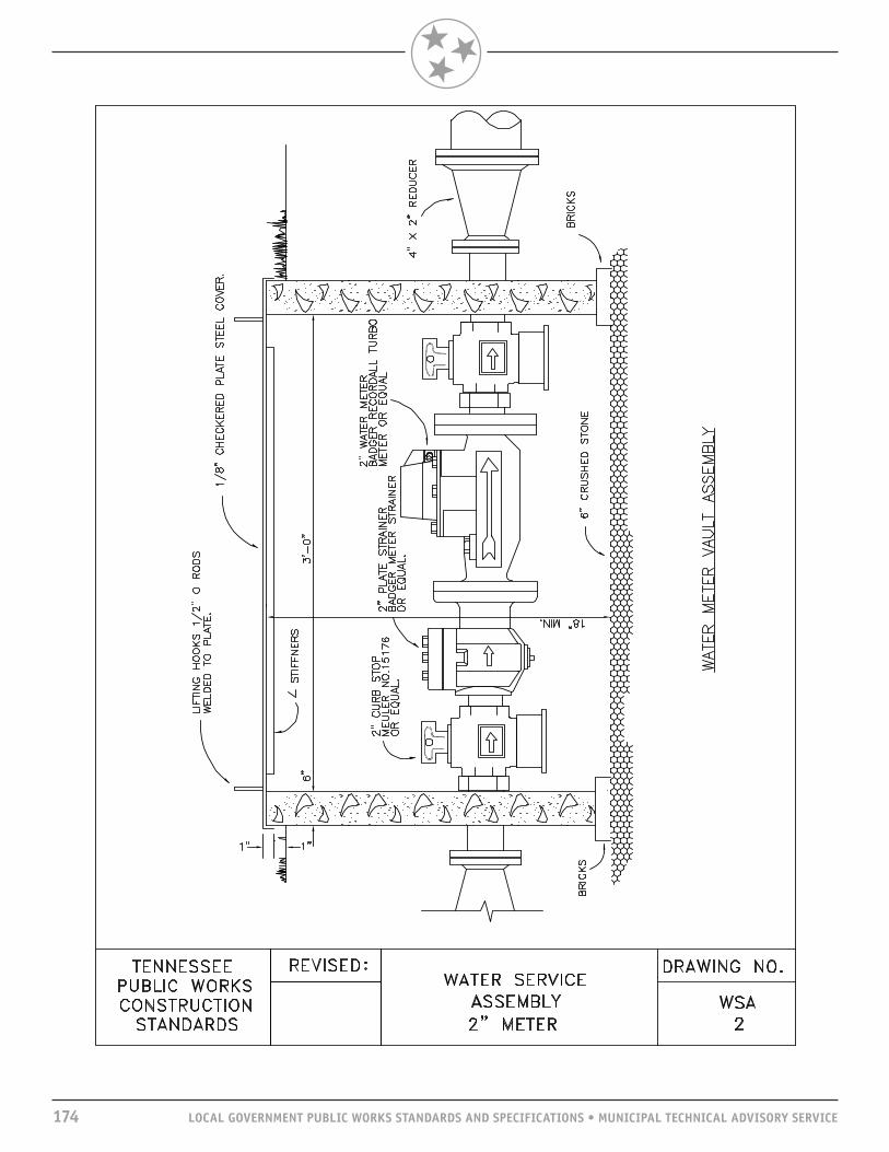
174 LOCAL GOVERNMENT PUBLIC WORKS STANDARDS AND SPECIFICATIONS • MUNICIPAL TECHNICAL ADVISORY SERVICE

LOCAL GOVERNMENT PUBLIC WORKS STANDARDS AND SPECIFICATIONS • MUNICIPAL TECHNICAL ADVISORY SERVICE 175
SCOPEThis section pertains to the requirements for submitting plans and specifications to the Tennessee Department of Environment and Conservation in order to obtain approval to construct sanitary sewers.
Much of the design criteria presented has been taken from Chapter 2, State of Tennessee, Design Criteria for Sewage Works.
ENGINEER’S REPORTAn Engineer’s report shall be submitted to the Tennessee Department of Environment and Conservation Division of Water Pollution Control (TDEC-WPC) when it is required by the funding agency and when a sewage collection system is being created or expanded. The Engineer’s report shall be submitted for review prior to the preparation of final plansand at least 30 days prior to the date on which action by the TDEC-WPC is desired. The Engineer’s report shall address all appropriate points as set forth by the TDEC-WPC.
PLANNING FACTORSGENERALIn general, and except for special reasons, the Tennessee Department of Environment and Conservation Division of Water Pollution Control (TDEC-WPC) will approve plans for new systems or extensions for existing systems. Design criteria and hydraulic calculations must be submitted on all projects. Rainwater from roofs, streets, and other areas, and groundwater from foundation drains shall be excluded from the wastewater collection system.
DESIGN PERIODIn general, sewer systems shall be designed for the estimated ultimate tributary population except when considering parts of the system that can be readily increased in capacity. Similarly, consideration shall be given to the maximum anticipated capacity of institutions.
Selection of the design period for trunk and interceptor sewers should be based on evaluation of economic, functional, and other considerations. Some of the factors that should be considered in the evaluation are 1. Possible solids deposition, odor, and pipe corrosion that might occur at initial flows; 2. Population and economic growth projections and the accuracy of the projections; 3. Comparative costs of staged construction alternatives; and 4. Effect of sewer sizing on land use and development.
DESIGN FACTORSIn determining the required capacity of sanitary sewers, the following factors shall be considered: 1. Peak sewage flows from residential, commercial, institutional, and industrial sources; 2. Groundwater infiltration and exfiltration; 3. Topography and depth of excavation; 4. Treatment plant location; 5. Soil conditions; 6. Pumping requirements; 7. Maintenance, including manpower and budget; 8. Existing sewers; 9. Existing and future surface improvements; and10. Controlling service connection elevations.
DESIGN CRITERIAWASTEWATER SYSTEMS

176 LOCAL GOVERNMENT PUBLIC WORKS STANDARDS AND SPECIFICATIONS • MUNICIPAL TECHNICAL ADVISORY SERVICE
DESIGN BASISPer capita flow: New sewer systems shall be designed on the basis of an average daily per capita flow of wastewater of not less than 100 gallons per day when no water use information is available. This figure is assumed to cover normal infiltration, but an additional allowance shall be made where conditions are unfavorable. Generally, the sewers shall be designed to carry, when running full, not less than the following daily per capita contributions of wastewater, exclusive of wastewater from industrial plants: Laterals and submain sewers: 400 gallons Main, trunk, and outfall sewers: 250 gallons
Main, Trunk, and Interceptor Sewers: Minimum peak design flow should be not less than 250 percent of the average design flow.
Alternate method: When the need for deviations from the foregoing per capita rates is demonstrated, a brief description of the procedure used for sewer design shall be submitted to the Tennessee Department of Environment and Conservation. New sewer systems may be designed by alternative methods other than on the basis of per capita flow rates. Alternative methods may include the use of peaking factors of the contributing area, allowances for future commercial and industrial areas, separation of infiltration and inflow from the normal sanitary flow, and modification of per capita flow rates (based on specific data). Documentation of the alternative method used shall be provided. When infiltration is calculated separately from the normal sanitary flow, the maximum allowable infiltration rate shall be 25 gallons per day per inch diameter of the sewer per mile of sewer.
DETAILS OF DESIGN AND CONSTRUCTION—GRAVITY MAINSGENERALThis section pertains to the considerations to be made in designing gravity sewer mains.
MINIMUM SIZENo public sewer shall be less than 8” in diameter. Sewer service pipe shall be either 4” or 6” in diameter.
DEPTHIn general, sewers shall be deep enough to drain basement wastewater only and to prevent freezing.
SLOPEAll sewers shall be so designed and constructed to give mean velocities, when flowing half full, of not less than 2.0 feet per second, based on using an “n” of 0.013 for full flow in Manning’s formula. The required minimum slopes are as follows:
Required Minimum Slopes Sewer Size (feet/100 feet) 8 0.40 10 0.28 12 0.22 14 0.17 15 0.15 16 0.14 18 0.12 21 0.10 24 0.08 27 0.07 30 0.06 36 0.05

LOCAL GOVERNMENT PUBLIC WORKS STANDARDS AND SPECIFICATIONS • MUNICIPAL TECHNICAL ADVISORY SERVICE 177
ALIGNMENTSewers 24” or less shall be laid with straight alignment between manholes.
INCREASING SIZEWhen a smaller sewer joins a larger one, the invert of the larger sewer shall be lowered sufficiently to maintain the same energy gradient. An approximate method for securing these results is to place the 0.8 depth point of both sewers at the same elevation.
PIPE MATERIALS SELECTIONWhere velocities greater than 15 feet per second or a slope greater than 18.86 percent (for 8”) are attained, special provisions shall be made to protect against displacement by erosion and shock. Ductile iron pipe or similar material shall be used with mechanical joints and concrete anchors.
Any generally accepted material for sewers should be given consideration, but the material selected shall be adapted to local conditions, such as character of industrial wastes, possibility of septicity, discharge of force mains, soil characteristics, abrasion, and similar problems. Careful consideration should be given to pipes and compressive joint materials that are not chemically inert when they will be required to carry corrosive or solvent wastes. Such pipe material shall be evaluated for vulnerability to chemical attack, chemical/stress failure, and stability in the presence of common household chemicals such as cooking oils, detergents, and drain cleaners.
Rigid Pipe shall include, but not be limited to, vitrified clay, concrete, and cast iron pipe. Any rigid pipe shall have a minimum crushing strength of 2,000 pounds per lineal foot. All pipe should meet the appropriate ASTM and/or ANSI specifications.
Semi-rigid Pipe shall include, but not be limited to, polyvinyl chloride (PVC) composite (truss) pipe and ductile iron. PVC composite pipe ends shall be sealed. Rubber gasket joints shall be specified. All pipe should meet the appropriate ASTM and/or ANSI specifications.
Flexible Pipe shall include, but not be limited to, polyvinyl chloride pipe (PVC), polyethylene pipe (PE), fiberglass-composite pipe, reinforced plastic mortar pipe (RPM) and reinforced thermosetting resin pipe (RTR). PVC pipe should have a maximum standard dimension ratio (SDR) of 35. All other flexible pipe that is not classified by the SDR system should have the same calculated maximum deflection under identical conditions as the SDR 35 PVC pipe.
Flexible pipe deflection under earth loading may be calculated using the formula presented in the ASCE/WPCF publication Design and Construction of Sanitary and Storm Sewers.
All pipe should meet appropriate ASTM and/or ANSI specifications. It should be noted that ASTM D-3033 and D-3034 PVC pipes differ in wall thickness and have noninterchangeable fittings.
PIPE JOINTSThe method of making joints and the materials used should be included in the specifications. Sewer joints shall be designed to eliminate infiltration and to prevent the entrance of roots.
Elastomeric gaskets and other types of premolded (factory made) joints are required. Cement mortar joints and field solvent welds for pipe and fittings are not acceptable.
PIPELINE BEDDINGAll sewers shall be designed to prevent damage from superimposed loads. Proper allowance for loads on the sewer shall be made because of the width and depth of the trench. Backfill material up to three feet above

178 LOCAL GOVERNMENT PUBLIC WORKS STANDARDS AND SPECIFICATIONS • MUNICIPAL TECHNICAL ADVISORY SERVICE
the pipe shall not exceed 6” in diameter at its greatest dimension. As a general rule, in roadways where cover is less than four feet, or in open areas where cover is less than 21/2 feet, ductile iron pipe or concrete encasement shall be used. For structural reasons, ductile iron pipe, concrete encasement, or relocation shall be required when culverts or other conduits are laid such that the top of the sewer is less than 18” below the bottom of the culvert or conduit.
All pipe shall be bedded and completely encapsulated at minimum of 6” below the pipe to 6” above the top of the pipe with crushed stone or other approved Class I material.
Uncased borings are not permitted for pipe larger than 3”.
Special care shall be used in placing bedding in the haunch region.
MANHOLESLOCATIONManholes shall be installed at the upper end of each line, at all changes in grade, size or alignment, at all intersections, and at distances not greater than 350 feet. Greater spacing may be permitted in larger sewers and in those carrying a plant effluent. Systems equipped with proper tools and equipment may be allowed a greater distance between manholes when conditions warrant the need.
DROP MANHOLESA drop pipe shall be provided for a sewer entering a manhole at an elevation of 24” or more above the manhole invert. Where the difference in elevation between the incoming sewer and the manhole invert is less than 24”, the invert should be filleted to prevent deposition of solids.
SIZEThe minimum diameter of manholes shall be four feet. It is recommended that four feet be used for 8 to 15” pipe, five feet be used for 18 to 24” pipe, and six feet for larger. The minimum clear opening in the manhole frame shall be at least 24” in diameter.
FLOW CHANNELSFlow channels in manholes shall be of such shape and slope to provide smooth transition between inlet and outlet sewers and to minimize turbulence. A minimum slope of 0.1 foot drop across the bottom of the manhole must be provided to maintain cleaning and the hydraulic gradient. Channeling height shall be to the crowns of the sewers. Benches shall be sloped from the manhole wall toward the channel to prevent accumulation of solids.
BASE CONSTRUCTIONExcept for poured-in-place manholes, all bases shall be precast sections with preformed openings for rubber boots or cast-in-place rubber boots.
All manholes shall be placed on a sub-base foundation constructed from crushed stone or gravel. A poured concrete sub-base foundation should be used in extremely bad conditions.
WATERTIGHTNESSWatertight manhole covers shall be used wherever the manhole tops may be flooded. Manholes of brick or segmented block are not acceptable.
MANHOLE TESTING All new or rehabilitated manholes shall be vacuum tested to assure watertightness before backfilling. The exterior surface must be painted with waterproofing material as the vacuum is being pulled to seal the pores of the concrete.

LOCAL GOVERNMENT PUBLIC WORKS STANDARDS AND SPECIFICATIONS • MUNICIPAL TECHNICAL ADVISORY SERVICE 179
CONNECTIONSLine connections directly to the manholes or to short stubs integral with the manholes should be made with flexible joints. Flexible joints are joints that permit the manholes to settle without destroying the watertight integrity of the line connections.
VENTILATIONVentilation of gravity sewer systems should be considered where continuous watertight sections longer than 1,000 feet are incurred. Vent height and construction must consider flood conditions.
FRAMES, COVERS, AND STEPSFrames, covers, and steps shall be of suitable material and designed to accommodate prevailing site conditions and to provide for a safe installation. Materials used for manhole steps should be highly corrosion resistant. The use of galvanized steel should be avoided, and aluminum or plastic with reinforcing bar is preferred.
INSTALLATION AND ACCEPTANCE TESTINGAs a minimum, the specifications shall require acceptance testing to include visual, leakage, and where flexible pipe is selected, deflection testing. Detailed specifications for acceptance testing are stipulated in the technical specifications.
Before acceptance, each reach shall be visually inspected from manhole to manhole for grade, alignment, and defective materials or workmanship.
Low pressure air testing for all pipe shall be performed as specified in ASTM C-828.
All manholes shall be subjected to a vacuum test as specified in the detail specifications.
Nonrigid pipe shall be tested for proper backfill support by pulling a go/no-go mandrel or similar device through the pipeline.
PROTECTION OF WATER SUPPLIESWATER SUPPLY INTERCONNECTIONSThere shall be no physical connection between a public or private potable water supply system and a sewer or appurtenance thereto that would permit the passage of any wastewater or polluted water into the potable supply.
RELATION TO WATERWORKS STRUCTURESSewers shall be kept remote from public water supply wells or other water supply sources and structures.
Relations to Water MainsHorizontal Separation: Whenever possible, sewers shall be laid at least 10 feet horizontally from any existing or proposed water main. The distance should be measured edge to edge. Should local conditions prevent a lateral separation of 10 feet, a sewer may be laid closer than 10 feet to a water main if it is laid in a separate trench and if the elevation of the top (crown) of the sewer is at least 18” below the bottom (invert) of the water main.
Vertical Separation: Whenever sewers must cross under water mains, the sewer shall be laid at such elevation that the top of the sewer is at least 18” below the bottom of the water main. When the elevation of the sewer cannot be varied to meet this requirement, the water main shall be relocated to provide this separation or reconstructed with mechanical joint pipe to provide a distance of 10 feet to the joint on either side of the sewer. One full length of water main shall be centered over the sewer so that both joints will be as far from the sewer as possible.

180 LOCAL GOVERNMENT PUBLIC WORKS STANDARDS AND SPECIFICATIONS • MUNICIPAL TECHNICAL ADVISORY SERVICE
When it is impossible to obtain proper horizontal and vertical separation as stipulated above, both the water main and sewer shall be constructed of water main pipe and shall be pressure tested to assure watertightness.
RELATION TO STREAMSLocation of Sewers in StreamsThe top of all sewers entering or crossing streams shall be at a sufficient depth below the natural bottom of the stream bed to protect the sewer line. In general, the following cover requirements must be met:1. One foot of cover (concrete) is required where the sewer is located in rock;2. Three feet of cover is required in stabilized stream channels; and3. Seven feet of cover or more is required in shifting stream channels.
Sewers located along streams shall be located outside of the stream bed and sufficiently removed from it to minimize disturbance or root damage to streamside trees and vegetation.
Sewer outfalls, headwalls, manholes, gateboxes or other structures shall be located so they do not interfere with the free discharge of flood flows of the stream.
Sewers crossing streams shall be designed to cross the stream as nearly perpendicular to the stream flow as possible and shall be free from change in grade.
ConstructionSewers entering or crossing streams shall be constructed of ductile iron pipe with mechanical joints, concrete encased, or shall be otherwise constructed so that they will remain watertight and free from changes in alignment or grade. Sewer systems shall be designed to minimize the number of stream crossings. Construction methods that will minimize siltation shall be employed. Upon completion of construction, the stream shall be returned as nearly as possible to its original condition. The stream banks shall be seeded or planted, or other erosion prevention methods shall be employed to prevent erosion. Stream banks shall be sodded, if necessary, to prevent erosion. Where tree canopy has been removed, replacement trees of natural species shall be planted.
During construction, the contractor shall be prohibited from unnecessarily disturbing or uprooting trees and vegetation along the stream bank and in the vicinity of the stream, dumping soil and debris into streams and/or on banks of streams, changing course of the stream without encroachment permit, leaving cofferdams in streams, leaving temporary stream crossings for equipment, operating equipment in the stream, or pumping silt-laden water into the stream.
Provisions shall be made to retard the rate of runoff from the construction site and control disposal of runoff This can include liberal use of silt fencing to trap sediment resulting from construction in temporary or permanent silt-holding basins and pump discharges resulting from dewatering operations .Deposit all material and debris removed from the stream bed out of the flood plain area.
Project erosion and sediment control measures shall be in accordance with TDEC’s Tennessee Erosion and Sediment Control Handbook, most current edition.
Cleanup, grading, seeding, planting, and restoration of work area shall be carried out as early as practical as the construction proceeds.
Uncased borings are not permitted.

LOCAL GOVERNMENT PUBLIC WORKS STANDARDS AND SPECIFICATIONS • MUNICIPAL TECHNICAL ADVISORY SERVICE 181
Special Construction RequirementSpecial design requirements shall be employed to prevent stream drainage from sinking at the crossing and following along the sewer pipe bedding. This can be accomplished with an in-trench impounding structure of compacted clay.
Aerial CrossingsSewers laid on piers across ravines or streams shall be allowed when no other practical alternative exists or when other methods will not be as reliable.
Support shall be provided for all joints. All supports shall be designed to prevent frost heave, overturning and settlement. Precautions against freezing, such as insulation or increased slope, shall be provided. Expansion jointing shall be provided between aboveground and belowground sewers. The impact of flood waters and debris shall be considered. The bottom of the pipe should be placed no lower than the elevation of the 50-year flood stage.
PermitsIt is the owner’s responsibility to obtain all necessary permits along streams or rivers; i.e., Corps of Engineers, TVA, or the Natural Resources Section of the Division of Water Pollution Control.
APPURTENANCEService connections may have been accommodated by providing well-marked and recorded tees and/or wyes in the mains as they were constructed. Where tees or wyes exist, they shall be used for connecting new services.
When tapping an existing line (where a tee or wye does not exist), a special machine for tapping sewers shall be used. A tapping saddle shall be used to make a watertight connection.
PREPARATION OF PLANS—SANITARY SEWER FACILITIESGENERALEach plan sheet shall bear an appropriate title block showing the name of the project, location, owner, engineer, date, scale in feet, true north (or plan north with true reference) and where applicable, sheet number and revision data.
Each sheet shall contain a blank area at least 3” x 4” near the title block for imprinting the official “Approved for Construction” stamp of TDEC. Plans shall be clear and legible and shall conform to the requirements of the regulations. Plans shall be printed on sheets approximately 24” by 36”, with all sheets the same size. All sheets shall bear the stamp and signature of a professional engineer licensed to practice sanitary engineering by the state of Tennessee.
GENERAL PLANA plot plan of the existing and proposed sewers shall be submitted for projects involving new sewer systems or substantial additions to existing systems. This plan shall show the following:
Geographical Features1. Topography and elevations. Existing or proposed streets and all streams or water surfaces shall be clearly shown. Contour lines at suitable intervals shall be included.2. Streams. The direction of flow in all streams and high- and low-water elevations of all water surfaces at sewer outlets and overflows shall be shown.3. Boundaries. The boundary lines of the Owner’s property, municipality, sewer district, or area to be sewered shall be shown.

182 LOCAL GOVERNMENT PUBLIC WORKS STANDARDS AND SPECIFICATIONS • MUNICIPAL TECHNICAL ADVISORY SERVICE
SewersThe Plans shall show the location, size, and direction of flow of all existing and proposed sewers draining to the treatment works concerned. Hydraulic calculations are required for all lines in the project. All lines receiving discharge from the project shall be shown to be adequate. A vicinity map must accompany all sewer line extensions showing the flow route to the treatment facilities. Hydraulic calculations of pumping stations and sewer lines must be furnished, taking into consideration existing loading plus projected loading from developments under construction as well as the projected loading from the proposed extension.
DETAIL PLANSDetail plans shall be submitted. Plans and profiles are required for all wastewater lines. Profiles shall have a horizontal scale of not more than 100 feet to the inch. The plan view shall be drawn to a corresponding horizontal scale. Plans and profiles shall be drawn on the same sheet and will show
1. Location of streets and sewers;2. Line of ground surface; size, material, and type of pipe; length between manholes, inverts, and surface
elevation at each manhole; and grade of sewer between each two adjacent manholes. All manholes shall be numbered on the plans and correspondingly numbered on the profiles. Where there is any question of the sewer being sufficiently deep to serve any residence or other source, the elevation and location of the basement floor or other low point source shall be plotted on the profile of the sewer that is to serve the house or source in question. The Engineer shall state that all sewers are sufficiently deep to serve adjacent basements or sources except where otherwise noted on the plans;
3. Locations of all special features such as inverted siphons, concrete encasements, elevated sewers, etc.;4. All known existing structures, both above and belowground, that might interfere with the proposed
construction, particularly water mains, gas mains, storm drains, etc.; and5. Special detail drawings, made to a scale to show clearly the nature of the design, shall be furnished to show the following particulars: A. All stream crossing and sewer outlets, with elevations of the stream bed and of normal and extreme
high- and low-water levels to include the 100 year flood plain; B. Details of all special sewer joints and cross sections; and C. Details of all sewer appurtenance such as manholes, inspection chambers, flush valves, inverted
siphons, regulators, tide gates, and elevated sewers.
AS-CONSTRUCTED DRAWINGSFollowing the end of construction of the wastewater facilities, the tracings shall be revised to reflect any deviations from the Plans and provide the precise field location of the water mains, valves, hydrants, services, and other appurtenances. Permanent reproducible copies of the as-constructed drawings (as-builts) and/or electronic format copies shall be submitted to the TDEC-WPC and city or utility officials, while the Engineer shall keep the tracings/electronic files available for future reference and additional prints if required.
WASTEWATER SYSTEMSTANDARD DRAWINGSThe following drawings supplement the design criteria. Some are referenced in the criteria, while others need no discussion.

LOCAL GOVERNMENT PUBLIC WORKS STANDARDS AND SPECIFICATIONS • MUNICIPAL TECHNICAL ADVISORY SERVICE 183

184 LOCAL GOVERNMENT PUBLIC WORKS STANDARDS AND SPECIFICATIONS • MUNICIPAL TECHNICAL ADVISORY SERVICE

LOCAL GOVERNMENT PUBLIC WORKS STANDARDS AND SPECIFICATIONS • MUNICIPAL TECHNICAL ADVISORY SERVICE 185

186 LOCAL GOVERNMENT PUBLIC WORKS STANDARDS AND SPECIFICATIONS • MUNICIPAL TECHNICAL ADVISORY SERVICE

LOCAL GOVERNMENT PUBLIC WORKS STANDARDS AND SPECIFICATIONS • MUNICIPAL TECHNICAL ADVISORY SERVICE 187

188 LOCAL GOVERNMENT PUBLIC WORKS STANDARDS AND SPECIFICATIONS • MUNICIPAL TECHNICAL ADVISORY SERVICE

LOCAL GOVERNMENT PUBLIC WORKS STANDARDS AND SPECIFICATIONS • MUNICIPAL TECHNICAL ADVISORY SERVICE 189

190 LOCAL GOVERNMENT PUBLIC WORKS STANDARDS AND SPECIFICATIONS • MUNICIPAL TECHNICAL ADVISORY SERVICE

LOCAL GOVERNMENT PUBLIC WORKS STANDARDS AND SPECIFICATIONS • MUNICIPAL TECHNICAL ADVISORY SERVICE 191
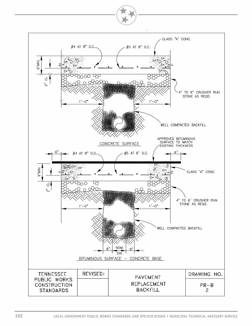
192 LOCAL GOVERNMENT PUBLIC WORKS STANDARDS AND SPECIFICATIONS • MUNICIPAL TECHNICAL ADVISORY SERVICE

LOCAL GOVERNMENT PUBLIC WORKS STANDARDS AND SPECIFICATIONS • MUNICIPAL TECHNICAL ADVISORY SERVICE 193

194 LOCAL GOVERNMENT PUBLIC WORKS STANDARDS AND SPECIFICATIONS • MUNICIPAL TECHNICAL ADVISORY SERVICE

LOCAL GOVERNMENT PUBLIC WORKS STANDARDS AND SPECIFICATIONS • MUNICIPAL TECHNICAL ADVISORY SERVICE 195
SCOPEThe purpose of compiling these criteria for standard procedures in storm sewer design and subsurface drainage is to develop improved routine methods of planning, designing, and checking storm sewer plans. It covers the reference information needed, design procedures, and standard details. This is not expected to cover extraordinary situations.
GENERALSTORM WATERStorm waters shall generally be carried in storm sewer systems on the basis of criteria established in this section and subject to final determination and approval of the Engineer.
An NPDES Storm Water Construction Permit is required by operators of construction sites on which there is clearing, grading or excavation that result in an area of disturbance of one or more acres, and activities that result in the disturbance of less than one acre if it is part of a larger common plan of development or sale. Please note this rule applies to construction activities begun before March 10, 2003, if one or more acres will be disturbed on or after March 10, 2003.
Permitted activities have included housing subdivisions, commercial and industrial buildings, golf courses, utility lines, sewage treatment plants, and roads. Various land clearing activities such as borrow pits for fill material have also been covered under this general permit.
PROTECTIONStorm sewer systems shall be designed to have the return period as designed by the controlling authority so as to prevent flooding of improvements by . Return periods are discussed under “Runoff Calculations and Criteria.” Design of the system shall provide a minimum of 1.0 foot of freeboard.
STORM SEWER SYSTEMSSystems shall be designed to protect against flooding of property of all classes and to maintain the required level of service for public facilities. Storm sewer systems shall be designed as a coordinated unit and may include any or all of the following elements:1. Enclosed storm sewers and appurtenances;2. Open channels; and3. Swales on property lines and/or back lot lines.
Enclosed sewers shall be used to collect and convey drainage on, across, and through public street rights-of-way. Outfall drains shall extend at least 60 feet to the rear of the front building line or 20 feet past the back line of the structure, whichever is greater, and on the inlet to one foot from the center of the side ditch.
Open channels are acceptable only to carry stormwater runoff from tributary areas exceeding 100 acres, or from smaller tributary areas otherwise requiring an enclosed storm sewer pipe 48” in diameter or larger, except drainage structures shall be provided where open channels cross public right-of-way.
DESIGN CRITERIADRAINAGE SYSTEMS

Side ditches generally are not acceptable and may be used to convey drainage along public rights-of-way only in rural areas when designated by the city engineer. Culverts and appurtenant drainage facilities shall be designed to permit their incorporation into a future enclosed storm sewer system when possible. Ditches shall be designed to meet the requirements for open channels.
VELOCITYDischarge velocity shall be controlled to prevent both erosion and siltation at and immediately downstream from the point of discharge. Energy dissipating structures shall be used if required.
DESIGN PROCEDURESMAPSPrints showing the watershed area, recorded plats, survey maps, or other plans that are available showing the tributary area shall be obtained.
SURVEYSCheck and confirm survey reference data with the official plat book and other recorded information.
UTILITIESThe location of all utility lines, existing and proposed, from files and other information supplied by utility companies and city records shall be checked.
EXISTING INFORMATIONDetermine the ridge lines of the tributary area and establish the general routing of the proposed storm sewer. Check connecting storm sewer lines, appurtenances, street grades, and all other information pertaining to the location of the proposed sewer.
PRELIMINARY LAYOUTPrepare the preliminary layout and grades in pencil. The drainage pattern must be compatible with the existing pattern established in the area.
ULTIMATE DEVELOPMENTCompute the estimated ultimate density and impervious surfaces of the area. Information may be obtained from the city engineer’s office or the planning and zoning department.
FIELD CHECKVerify the preliminary design by field checking the watershed area, critical connections, crossings, slopes, etc., before proceeding with the final draft of the plan.
RUNOFFEstablish and indicate curb grades, outline of the runoff area, and cubic feet per second by increment at each point of interception.
CURB CAPACITYCalculate curb capacities for each side of the street interdependently. Differences in curb elevations, off center crowns, etc., must be taken into consideration.
INLETSWhen calculations indicate that curb capacities are exceeded at a point, no further allowance shall be made for flow beyond that point, and basins shall be used to intercept flow at that point. All flow shall be picked up by an inlet. Paved gutters may be used to intercept flow and drained to an approved outfall on approval of the Engineer.
196 LOCAL GOVERNMENT PUBLIC WORKS STANDARDS AND SPECIFICATIONS • MUNICIPAL TECHNICAL ADVISORY SERVICE

LOCAL GOVERNMENT PUBLIC WORKS STANDARDS AND SPECIFICATIONS • MUNICIPAL TECHNICAL ADVISORY SERVICE 197
INLET AND PIPE CAPACITYCalculate capacities for inlets and size pipe laterals. A 15” pipe is the minimum size for all laterals.
MAXIMUM DEPTHDrainage water must not exceed the depth of the curb at any intersection. This maximum drainage water depth is further limited in duration as stipulated in Subsection 308.3.
HYDRAULICSCalculate and show hydraulics of pipe inlets. Calculate velocity head and hydraulic profiles of flows exceeding a velocity of 15 feet per second.
RUNOFF CALCULATIONS AND CRITERIAThe rational method of calculating storm water quantities, Q = CIA, shall be used with the following definitions of terms and arbitrary values:
Q is the quantity of runoff in cubic feet per second and is used as a basis for design of the storm drainage system.
C is the percentage of imperviousness of the area and shall have the following values where applicable:For all watertight roof surfaces .................................................................... .75 to .95For asphalt runway pavements ..................................................................... .80 to .95For concrete runway pavements ................................................................... .70 to .90For gravel or macadam pavements ................................................................ .35 to .70*For impervious soils (heavy) ...................................................................... .40 to .65*For slightly pervious soils .......................................................................... .15 to .40*For slightly pervious soils, with turf ........................................................... .10 to .30*For moderately pervious soils ..................................................................... .05 to .20*For moderately pervious soils, with turf ...................................................... .00 to .10
* = For slopes from one percent to two percent.
I is intensity of rainfall in inches per hour and shall be determined for the yearly frequency specified below and as specified from the intensity duration curves attached to this criteria: 10 years (return period): Rural and fringe areas with low volume streets. 25 years (return period): Residential areas. 50 years (return period): Major drainage channels in residential and commercial areas, arterial street culverts, and open channel slopes.100 years (return period): Critical areas, flood plains in commercial areas and natural flood plains in residential areas.
A is the area in acres contributing to the drainage system. All upstream tributary areas are to be considered fully developed as zoned at the time of design.
TOC Time of concentration equals the inlet time plus the time for water to flow down the pipe or channel to the point at which the peak flow is to be determined. The inlet time shall be figured taking into account the topography, size, and surface characteristics of the contributing area but shall not exceed 15 minutes unless detailed calculations justifying longer periods are submitted.
PIPE SIZINGMANNING FORMULAPipe size in integrated underground systems normally will be determined in accordance with the Manning formula:
V = 1.5 r2/3 s1/2 N

Culverts shall be sized based on Hydraulic Design Series 3, 4, 5 and Hydraulic Engineering Circular 12 as published by the Federal Highway Administration. The value of N in the Manning formula shall be as designated below. The exception will be in cases where slopes are above the critical. Pipe sizing shall then be determined by entrance control. Head shall be considered up to a point where inundation will not cause damage to properties.
The coefficients of friction allowed for the various kinds of pipe are as follows:Portland cement concrete ..............................................................N = 0.013Corrugated metal ..........................................................................N = 0.023Corrugated metal with paved invert .................................................N = 0.021Smooth flow corrugated metal ........................................................N = 0.013Vitrified clay pipe .........................................................................N = 0.013Asbestos cement ..........................................................................N = 0.012Corrugated polyethylene—smooth interior .......................................N = 0.012
MINIMUM PIPE SIZEThe minimum size storm sewer shall be 15” in diameter.
VELOCITYAll storm drainage systems shall be designed so as to maintain a minimum velocity of flow of three feet per second and a maximum velocity of 15 feet per second when flowing full.
VELOCITY HEADLarge quantities or masses of water flowing at a high rate of speed contain a large amount of kinetic energy, which in hydraulics is defined as velocity head (V2/2g).
Any change in cross section or restrictions in pipes or inlets shall be considered energy losses and shall be taken into consideration in the design of the system.
SLOPEAll sewers shall be designed and constructed to give mean velocities when flowing full of not less than three feet per second. The following pipe sizes and minimum slopes are listed for information purposes. Slopes shall be shown on plans in percent.
Sewer -------- Minimum Slope—Percent --------Size n=0.013 n=0.019 n=0.021
15” 0.33% 0.70% 0.85%18” 0.26% 0.55% 0.65%21” 0.20% 0.45% 0.55%24” 0.17% 0.36% 0.45%(Note: Percent is specified for purposes of compatibility with nomenclature used on current laser equipment.)
LOCATIONStorm drainage lines generally shall be located in the parkway area and shall be placed as shown on the approved submitted plans.
DEPTH OF COVERAll storm drainage lines shall have a minimum cover of 18” where practical. Cover may be decreased to avoid conflicts or on short laterals. Special bedding or protection shall be required where cover is decreased to less than 18”.
198 LOCAL GOVERNMENT PUBLIC WORKS STANDARDS AND SPECIFICATIONS • MUNICIPAL TECHNICAL ADVISORY SERVICE

LOCAL GOVERNMENT PUBLIC WORKS STANDARDS AND SPECIFICATIONS • MUNICIPAL TECHNICAL ADVISORY SERVICE 199
DRAINAGE INLETSLOCATIONProvide inlets to maintain a reasonable level of vehicular and pedestrian traffic service as follows:
GENERALContain all flow within street curbs during the design storm.
ARTERIAL AND COLLECTION STREETSLimit gutter flow width to prevent encroachment on the center 24 feet of street during runoff occurring 50 percent of peak design rates of the design storm.
Good design does not allow flow across intersections. Where economic and other factors control, the following would apply. Limit gutter flow across intersections with arterial or collector class streets to provide a maximum flow not greater than the following:
Longitudinal Gutter Slope ..................................................... Flow C.F.S.0.5% ........................................................................................0.301.0% ........................................................................................0.452.0% ........................................................................................0.603.0% ........................................................................................0.704.0% ........................................................................................0.705.0% and over ...........................................................................1.00
RESIDENTIAL STREETSLimit gutter flow width to prevent encroachment on the center 14 feet of street during runoff occurring 50 percent of peak design rates of the design storm.
Limit gutter flow across intersections with arterial or collector class streets as provided for arterial street intersections.
PEDESTRIAN CROSSWALKGutter flow across major pedestrian crosswalks, including marked crosswalks on streets bordering school grounds, pedestrian signal controlled crosswalks, and crosswalks in retail business areas, shall be limited as provided for arterial street intersections.
OPEN CHANNELSGENERALOpen channels shall be sized to carry design rates of flow without significant damage or erosion to the channel. Channels shall be fenced, sloped, or otherwise protected to prevent injury to the public.
CONNECTIONSPipe culverts, box culverts, and other structures entering channels shall not project into the normal waterway area.
VELOCITYChannel design shall include lining or treatment of the invert and sides as required to minimize erosion. Minimum treatment shall include seeding. Channel inverts and sides shall be lined to a height one foot above the hydraulic grade line produced by a flow rate of 60 percent of the peak design rate of the design storm in accordance with the following table:

Mean Flow Velocity Type of Lining3 F.P.S. & less .......................................................................Seeded3 - 8 F.P.S. ...........................................................................Sod8 - 15 F.P.S. .........................................................................Rip-rap or concreteOver 15 F.P.S. .......................................................................Concrete paved
Lining materials having equivalent erosion control properties to those shown in the previous table may be used in lieu thereof.
CAPACITYOpen channels shall be sized to carry design flow rates with one foot of freeboard.
SECTIONSChannel sections shall be compatible with the type of lining and maintenance practice to be used. Side slopes shall not be steeper than two horizontal to one vertical. Channels lined with sod, grass, or other vegetative ground cover and having slopes steeper than three horizontal to one vertical are not readily susceptible to mowing. Friction factors used in design shall be considered in selecting type of lining.
CHECK DAMSCheck dams may be used to control flow velocity in open channels. Check dams shall be designed to prevent flow bypass by undercutting or erosion around the ends. Adequate paving or rip-rap shall be provided at the downstream toe of check dams to prevent erosion or loss of foundation supported by undercutting. Wood may be used for temporary check dam construction only.
NATURAL CHANNELSNatural channels of adequate capacity and having stable banks and invert may be used without modification.
DESIGN DETAILSPLANThe plan view of all storm sewer details shall indicate the proper location of the storm sewer, appurtenances, size of line, capacity, and other details relating to the storm drainage system. The plan shall show sufficient detail to include exact locations, proper ties into existing permanent reference points, proper angles, and distances from other utilities to be placed or presently in the street right-of-way. Easement shall be a minimum of 14 feet for enclosed structures and 20 feet for open paved channels where they cross private property or as designated by the city engineer.
PROFILEThe profile of all storm sewers shall show the necessary slope, existing and proposed street grades, locations of angles and appurtenances, and proper elevations for existing outfall ditches. The profile shall indicate the size of line and the capacity of each line as determined by the design engineer. The total area draining to each basin and the Q that will be required to be dissipated at that point shall also be indicated, on either plan or profile.
EASEMENTSPermanent drainage easements shall be obtained for all storm sewers and open drains that are not within a public dedication, with the right of entry for inspection and maintenance.
Permanent easements shall be obtained for a retention dam site with spillway and release facilities, and floodage rights for temporary detention and conveyance of storm drainage. Easements and floodage rights shall include all necessary provisions and sufficient land for entry to inspect and maintain facilities. Deeds and easements shall be properly recorded.
200 LOCAL GOVERNMENT PUBLIC WORKS STANDARDS AND SPECIFICATIONS • MUNICIPAL TECHNICAL ADVISORY SERVICE

LOCAL GOVERNMENT PUBLIC WORKS STANDARDS AND SPECIFICATIONS • MUNICIPAL TECHNICAL ADVISORY SERVICE 201
SUGGESTED STORM SEWER DESIGN CHECK LISTo 1. Control—Scale: horizontal 1” = 100’, vertical 1” = 10’o Large scale for detailso Drawing number and dateo North arrowo Signature blockso 2. Boundary lines: counties, cities, sewer districts, drainage area, etc.o 3. Subdivision: name and location by sectiono 4. Streets: names and widthso 5. Easements: R.O.W. 6. Survey data complete:o Curve date—Where curved sewersare placedo Line, grade and depth—dimensioned and specified 7. Pipe size and class:o Existing lineso Proposed lines—size, length, and covero Connectionso Elevations and grades showno 8. Manholes: designation, spacing, and invert elevations showno 9. Location and depth of existing utilities, cable, and structures as available from recordso 10. Test hole data if requiredo 11. Structural details adequate o 12. Removals and replacements—trees, poles, paving, etc.o 13. Sealed by professional engineer
TEMPORARY DETENTIONGENERALProvisions of areas for the temporary, controlled detention of storm drainage and its regulated discharge to the downstream storm sewer system at peak rates less than would occur without such facilities may be included in storm sewer systems development upon specific approval of the city engineer unless required under the NPDES General Construction Permit. If they are required, such provisions are mandatory and shall be in accordance with the Tennessee Erosion and Sediment Control Manual, most current edition.
PERFORMANCE CRITERIAThe design storm shall be a storm of 24-hour duration having the return periods set forth in Runoff Calculations and Criteria for enclosed structures.
Detention storage areas shall have adequate capacity to contain maximum required volume of tributary storm drainage runoff with one foot of freeboard. Adequate provisions and allowances shall be made for the accumulation and removal of silt.
Outlet works shall be designed to limit peak outflow rates from detention storage areas to or below peak flow rates that would have occurred prior to the proposed or zoned development of the tributary area.
1. Outlet works shall not include any mechanical components or devices and shall function without requiring attendance or control during operation.2. Size and hydraulic characteristics shall be such that all water in detention storage is released to the downstream storm sewer system within 24 hours of the end of the design rainfall.
Detention storage systems shall be designed to accept storm drainage runoff from the entire area tributary thereto, regardless of ownership of lands included within the tributary area.
Emergency spillways shall be provided to permit safe passage of water from storms producing runoff in excess of the design storm.
DESIGN DATA SUBMITTALIn addition to complete plans, the following design data shall be submitted for the city engineer’s approval for all projects including temporary detention facilities:
1. Runoff hydrograph plotted in units of inches per hour, runoff rate of the tributary area as ordinates, and time from the start of runoff as abscissas. The runoff hydrograph shall be developed to include all storms of lesser duration within the 24-hour storm.2. Area: capacity curve for proposed detention facility plotted in units of datum elevation as ordinates, and cumulative volume of storage as abscissas.3. Discharge characteristics curve of outlet works plotted in units of detention facility water surface elevation as ordinates, and discharge rate in C.F.S. as abscissas.4. Combined storage: outflow curves showing both inflow and discharge in units of accumulated volume as ordinates, and time from the start of runoff as abscissas. A. Curves shall be arranged so that the vertical distance between the accumulated storage and accumulated discharge will indicate the net volume in storage at any point in time. B. Curves shall be extended to the time required for complete discharge of all runoff stored in the detention facility.
LAND REQUIREMENTSPermanent easements for the temporary impoundment of storm water runoff shall be dedicated to the city. The permanent easement shall include all lands, structures, and facilities to be used for temporary detention and conveyance of storm drainage. Easements shall include all necessary provision and land necessary for the city’s right of entry for purposes of inspection and/or maintenance. All instruments and easements shall be subject to the approval of the city.
MAINTENANCEProvisions shall be made that are acceptable to the city for perpetual maintenance of detention facilities, outlet works, and appurtenances.
PERMITSBuilding permits for projects, including temporary detention facilities, may be granted by the city only after all easements have been dedicated, accepted, and recorded, and all required maintenance agreements, contracts, and bonds have been executed.
METHODS TO REDUCE QUANTITY OF RUNOFF AND MINIMIZE POLLUTIONIf the stormwater is permitted to follow its natural hydrological process, it will inevitably result in a reduction in the quantity of stormwater runoff and a reduction of pollution loading in the receiving watercourses. Stormwater shall be directed into the soil preferably to the same extend as nature did prior to development, and maybe to an even greater extent. By allowing stormwater to infiltrate back into the soil, it will not only reduce the quantity of runoff and recharge to water table, but the filtering properties of the soil will improve the water quality.
Whatever amount cannot be so accommodated at the point of rainfall shall be detained in nearby locations for a controlled outlet to the receiving streams, with peak flows approaching the predevelopment peak flows.
There are a variety of methods in common use today that can effectively control peak runoff rates, while at the same time, improving quality. The following table lists such methods along with their effectiveness. You also may consult the TDEC Guide to the Selection & Design of Stormwater Best Management Practices (BMPs), most current edition.
202 LOCAL GOVERNMENT PUBLIC WORKS STANDARDS AND SPECIFICATIONS • MUNICIPAL TECHNICAL ADVISORY SERVICE

LOCAL GOVERNMENT PUBLIC WORKS STANDARDS AND SPECIFICATIONS • MUNICIPAL TECHNICAL ADVISORY SERVICE 203
Measures for Reducing Quantity of Runoff and Minimizing Pollution
REDUCE REDUCE IMPROVE- VOLUME PEAK MENTS TO AREA TYPE* OF RATE OF RUNOFF RUNOFF RUNOFF QUALITY MEASURE RES INS COM IND HWY
Roof water to grassed surfaces x x x x
Contour Grading x x x
Porous Pavement
• interlocking stones x x x x x x
• graveled surfaces x x x x x x
• porous asphalt x x x x x x x
Grassed Ditches x x x x x x x x
Infiltration Basins x x x x x x x x
Blue-Green Storage x x x x x
Ponding on flat roofs x x x x
Ponding on roadways x x
Ponding on parking lots x x x x
Detention Ponds (dry pond) x x x x x x x
Retention Ponds no freeboard x
Retention Ponds with freeboard x x x x x x
Subsurface Disposal
• perforated storm sewer x x x x x x x x
• infiltration trenches x x x x x x x x
• dry wells x x x x x x x x
Subsurface Detention x x x x x x x
*AREA TYPES All of these measures for reducing quantity of runoff and minimizingRes—Residential pollution are not applicable to every city, but many are, and the runoffIns—Institutional can be reduced by using those that are suited to the varying conditions.Com—CommercialInd—IndustrialHwy—Highways

DRAINAGE SYSTEMSTANDARD DRAWINGS AND DESIGN CHARTSThe following drawings supplement the criteria. Some are referenced in the criteria, while others need no discussion.
204 LOCAL GOVERNMENT PUBLIC WORKS STANDARDS AND SPECIFICATIONS • MUNICIPAL TECHNICAL ADVISORY SERVICE

LOCAL GOVERNMENT PUBLIC WORKS STANDARDS AND SPECIFICATIONS • MUNICIPAL TECHNICAL ADVISORY SERVICE 205

206 LOCAL GOVERNMENT PUBLIC WORKS STANDARDS AND SPECIFICATIONS • MUNICIPAL TECHNICAL ADVISORY SERVICE

LOCAL GOVERNMENT PUBLIC WORKS STANDARDS AND SPECIFICATIONS • MUNICIPAL TECHNICAL ADVISORY SERVICE 207

208 LOCAL GOVERNMENT PUBLIC WORKS STANDARDS AND SPECIFICATIONS • MUNICIPAL TECHNICAL ADVISORY SERVICE

LOCAL GOVERNMENT PUBLIC WORKS STANDARDS AND SPECIFICATIONS • MUNICIPAL TECHNICAL ADVISORY SERVICE 209

210 LOCAL GOVERNMENT PUBLIC WORKS STANDARDS AND SPECIFICATIONS • MUNICIPAL TECHNICAL ADVISORY SERVICE

LOCAL GOVERNMENT PUBLIC WORKS STANDARDS AND SPECIFICATIONS • MUNICIPAL TECHNICAL ADVISORY SERVICE 211

212 LOCAL GOVERNMENT PUBLIC WORKS STANDARDS AND SPECIFICATIONS • MUNICIPAL TECHNICAL ADVISORY SERVICE

LOCAL GOVERNMENT PUBLIC WORKS STANDARDS AND SPECIFICATIONS • MUNICIPAL TECHNICAL ADVISORY SERVICE 213

214 LOCAL GOVERNMENT PUBLIC WORKS STANDARDS AND SPECIFICATIONS • MUNICIPAL TECHNICAL ADVISORY SERVICE

LOCAL GOVERNMENT PUBLIC WORKS STANDARDS AND SPECIFICATIONS • MUNICIPAL TECHNICAL ADVISORY SERVICE 215

216 LOCAL GOVERNMENT PUBLIC WORKS STANDARDS AND SPECIFICATIONS • MUNICIPAL TECHNICAL ADVISORY SERVICE

LOCAL GOVERNMENT PUBLIC WORKS STANDARDS AND SPECIFICATIONS • MUNICIPAL TECHNICAL ADVISORY SERVICE 217

218 LOCAL GOVERNMENT PUBLIC WORKS STANDARDS AND SPECIFICATIONS • MUNICIPAL TECHNICAL ADVISORY SERVICE

LOCAL GOVERNMENT PUBLIC WORKS STANDARDS AND SPECIFICATIONS • MUNICIPAL TECHNICAL ADVISORY SERVICE 219

220 LOCAL GOVERNMENT PUBLIC WORKS STANDARDS AND SPECIFICATIONS • MUNICIPAL TECHNICAL ADVISORY SERVICE

LOCAL GOVERNMENT PUBLIC WORKS STANDARDS AND SPECIFICATIONS • MUNICIPAL TECHNICAL ADVISORY SERVICE 221

222 LOCAL GOVERNMENT PUBLIC WORKS STANDARDS AND SPECIFICATIONS • MUNICIPAL TECHNICAL ADVISORY SERVICE

LOCAL GOVERNMENT PUBLIC WORKS STANDARDS AND SPECIFICATIONS • MUNICIPAL TECHNICAL ADVISORY SERVICE 223

224 LOCAL GOVERNMENT PUBLIC WORKS STANDARDS AND SPECIFICATIONS • MUNICIPAL TECHNICAL ADVISORY SERVICE

LOCAL GOVERNMENT PUBLIC WORKS STANDARDS AND SPECIFICATIONS • MUNICIPAL TECHNICAL ADVISORY SERVICE 225

226 LOCAL GOVERNMENT PUBLIC WORKS STANDARDS AND SPECIFICATIONS • MUNICIPAL TECHNICAL ADVISORY SERVICE

LOCAL GOVERNMENT PUBLIC WORKS STANDARDS AND SPECIFICATIONS • MUNICIPAL TECHNICAL ADVISORY SERVICE 227
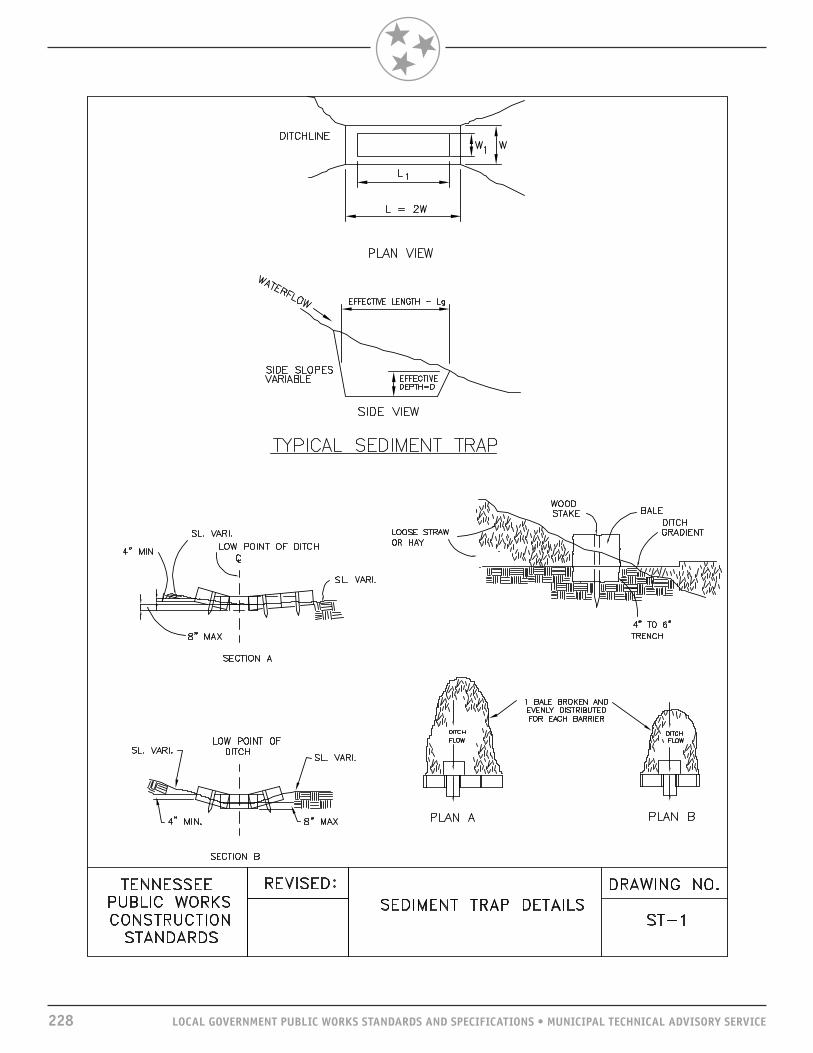
228 LOCAL GOVERNMENT PUBLIC WORKS STANDARDS AND SPECIFICATIONS • MUNICIPAL TECHNICAL ADVISORY SERVICE
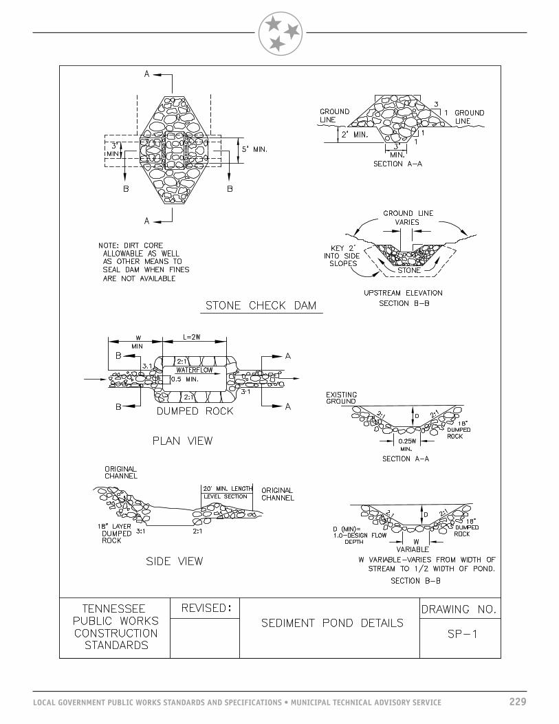
LOCAL GOVERNMENT PUBLIC WORKS STANDARDS AND SPECIFICATIONS • MUNICIPAL TECHNICAL ADVISORY SERVICE 229

230 LOCAL GOVERNMENT PUBLIC WORKS STANDARDS AND SPECIFICATIONS • MUNICIPAL TECHNICAL ADVISORY SERVICE

LOCAL GOVERNMENT PUBLIC WORKS STANDARDS AND SPECIFICATIONS • MUNICIPAL TECHNICAL ADVISORY SERVICE 231

232 LOCAL GOVERNMENT PUBLIC WORKS STANDARDS AND SPECIFICATIONS • MUNICIPAL TECHNICAL ADVISORY SERVICE

LOCAL GOVERNMENT PUBLIC WORKS STANDARDS AND SPECIFICATIONS • MUNICIPAL TECHNICAL ADVISORY SERVICE 233
SCOPE“Street” is a general term denoting a public way for purpose of vehicular travel including the entire area within the right-of-way.
GENERALThis section will consider all phases in the design of a street and problems to be considered and solved in order to complete the right-of-way and construction plans.
DESIGN ELEMENTSDESIGN TRAFFIC VOLUMESTraffic estimates used for the design of residential streets shall be expressed as average daily traffic (ADT) volumes. Design hour volumes shall be used for arterial and collector streets by making peak hour traffic assignments in lieu of ADT assignments.
DESIGN SPEED AND SIGHT DISTANCE
RELATION OF SIGHT DISTANCE TO DESIGN SPEED Design Speed MPH
20 30 40 50Minimum stopping sight distance, feet 115 200 305 425Minimum passing sight distance, feet N/A 1,090 1,470 1,835
ALIGNMENTTerrain has considerable influence on the final choice of alignment. Generally, the topography of an area fits into one of the following three classifications: flat, rolling, or hilly.
RELATION OF MAXIMUM GRADES TO DESIGN SPEED
Type of ARTERIALS COLLECTORS LOCAL ROADS & STREETS Topography Design Speed MPH Design Speed MPH Design Speed MPH
40 50 30 40 50 20 30 40 50 Flat 5% 4% 7% 7% 6% 8% 7% 7% 6% Rolling 6% 5% 9% 8% 7% 11% 10% 10% 8% Hilly 8% 7% 10% 10% 9% 16% 14% 13% 10%
In mountainous regions, steeper grades may be allowed but for short horizontal distances.
DESIGN CRITERIASTREETS

234 LOCAL GOVERNMENT PUBLIC WORKS STANDARDS AND SPECIFICATIONS • MUNICIPAL TECHNICAL ADVISORY SERVICE

LOCAL GOVERNMENT PUBLIC WORKS STANDARDS AND SPECIFICATIONS • MUNICIPAL TECHNICAL ADVISORY SERVICE 235
Maximum superelevation rates of 0.04 to 0.06 feet per foot should be used on arterial and collector streets. The lower value should be used where snow and ice are significant factors. This is particularly true on facilities with numerous structures, as bridge decks generally freeze more rapidly than other roadway sections. Superelevation on residential streets is usually not provided.
SUPERELEVATION RUNOFF PLUS TANGENT RUNOUT(Based on Transition from 2% Normal Cross-slope)
V=20 MPH V=30 MPH V=40 MPH V=50 MPHe(%) 2-Lane 4-Lane 2-Lane 4-Lane 2-Lane 4-Lane 2-Lane 4-Lane Lt+Lr Lt+Lr Lt+Lr Lt+Lr Lt+Lr Lt+Lr Lt+Lr Lt+Lr
1.5 0 0 0 0 0 0 0 02.0 64 98 72 110 82 124 96 1442.2 69 103 76 115 88 130 101 1512.4 72 106 81 119 92 136 106 1582.6 74 111 83 126 96 143 110 1662.8 77 117 87 130 99 149 115 1733.0 82 122 92 137 103 155 120 1803.2 85 127 94 141 107 161 125 1873.4 87 132 98 148 111 168 130 1943.6 90 137 101 152 115 174 134 2023.8 95 140 105 159 121 180 139 2094.0 98 146 110 164 125 186 144 2164.2 100 151 112 170 128 192 149 2234.4 103 156 116 175 132 199 154 2304.6 108 161 121 179 136 205 158 2384.8 111 166 123 186 140 211 163 2455.0 113 171 127 190 144 217 168 2525.2 116 174 132 197 150 223 173 2595.4 121 180 134 201 153 230 178 2665.6 124 185 138 208 157 236 182 2745.8 126 190 141 212 161 242 187 2816.0 129 195 145 219 165 248 192 288
Lt+Lr = Tangential Runout + Superelevation Runoff
Alignment design should be arranged so as to avoid superelevation transition on bridge decks in order to prevent ponding in the area of zero superelevation in the crown change zone.
The design of the roadway should be such to avoid edge of pavement profiles through superelevation transitions that are flatter than 0.5 percent to avoid pavement drainage problems in curbed sections and flatter than 0.2 percent on roadways without curbs.
PAVEMENT CROWNPlane sections should be used on urban streets with 0.018 to 0.020 feet of drop per foot of width.
Plane or curved sections may be used on residential streets with a total crown of at least 0.2 feet.
Pavement for undivided streets, regardless of the number of lanes, normally is sloped each way from the centerline.

236 LOCAL GOVERNMENT PUBLIC WORKS STANDARDS AND SPECIFICATIONS • MUNICIPAL TECHNICAL ADVISORY SERVICE
NUMBER OF LANESThe number of lanes required should be determined by the design hour volume (DHV). DHVs shall be obtained from the Tennessee Department of Transportation (TDOT) when available and current. When not available or current, DHVs should be determined from local studies by averaging the highest afternoon peak traffic flows for each week for a period of one year. DHVs shall be adjusted when necessary to consider future and/or seasonal traffic volumes.
In urban areas the number of lanes needed may be dictated by intersection capacities. The following chart provides an estimate of capacity for higher types of roadways for route planning purposes.
SUGGESTED SERVICE VOLUMES FOR INITIALESTIMATE OF NUMBER OF LANES
Trial Service VolumeType of Highway Design Speed–Miles/Hour Vehicles/Lane/Hour
Other Principal Arterial 55 800* 50 500**Minor Arterial 40 300***Collector 30 200***
*Assuming 60 percent green time **Assuming no parking and 45 percent green time***Assuming parking and 30 percent green time
ROADWAY WIDTHSRoadway widths are determined by the number of lanes required to accommodate the traffic. The minimum width for any roadway is 29 feet from back of curb to back of curb and included two 12-foot wide lanes. Minimum roadway cross section areas for different locations are shown in the standard detail drawings.
MEDIANWhen provided, medians should be a minimum of one traffic lane plus 2 feet when the median is not raised. Raised or depressed median widths of 16 to 60 feet are more desirable for streets with design speeds at 50 mph and higher. These wider median strips should be used and determined according to specific right-of-way restrictions such as building development, right-of-way costs, etc.
CURBS, GUTTERS, AND SIDEWALKSDimensions and other pertinent information for the various types of curbs, gutters, and sidewalks are shown on the detail drawings following this section.
The need for and width of sidewalks should be determined on the basis of specific densities of land development and volumes of pedestrian and vehicular traffic or as required by policies and regulations of local governments or the agency providing funding for the project. Sidewalk widths in central business districts and other high density areas may be determined objectively on the basis of capacity analyses. The quality and rate of pedestrian flow depend on the amount of space available per pedestrian. All sidewalks and curbs should be compliant with the Americans with Disabilities Act.
TRAFFIC CALMINGThe use of traffic calming devices should be considered as a part of the planning process in both residential and commercial developments.

LOCAL GOVERNMENT PUBLIC WORKS STANDARDS AND SPECIFICATIONS • MUNICIPAL TECHNICAL ADVISORY SERVICE 237
DRIVEWAYSLOCATION INTERIOR LOT Minimum distance from edge of driveway to property line: Residential—5 feet Commercial—12.5 feet
WIDTH Residential—minimum 10 feet, maximum 20 feet Commercial—20 feet maximum one way Commercial—40 feet maximum two way
DRIVEWAY ANGLE Two-way operation from two-way street—90 degrees One-way operation form two-way street—90 degrees One way for one-way operation with divided highway travel—60 degrees maximum and 45 degrees minimum
INTERSECTING RADIUS OF PAVEMENT Residential—minimum 5 feet, maximum 15 feet Commercial—minimum 5 feet, maximum 20 feet
DOUBLE DRIVEWAY25 feet minimum but not less than the adjacent width opening of driveway. Minimum distance between double driveways shall be 25 feet but not less than the width opening of the adjacent driveway.
CORNER CLEARANCEThe minimum corner clearance shall be 25 feet. Where there are traffic signals at the intersection, desirably the near side clearance should be two or more times the far side.
BRIDGE WIDTHThe following is recommended width for a two-lane road—one lane each way.
Design Volume Minimum Clear Distance Minimum Clear Distance(vehicles/day) for Roadways (without curbs)* for Roadways (with curbs)**
0-400 Traveled Way + 2 feet (each side) Curb-to-Curb Width401-2,000 Traveled Way + 3 feet (each side) Curb-to-Curb WidthOver 2,000 Full Roadway Width (including shoulders) Curb-to-Curb Width
*For bridges exceeding 100 feet in length, a minimum width of the traveled way plus 3 feet is acceptable.**Sidewalks should be carried across the bridge if they exist on the roadway. The width should be such to accommodate pedestrians outside of the traveled way.
LATERAL CLEARANCEWhere there is no curb and gutter or any obstruction in the shoulder or front slope of the roadside ditch, a guardrail shall be erected. All guardrails, guardrail terminals, sign posts, and other roadway appurtenances should be tested at the appropriate test level according to requirements of the National Cooperative Highway Research Program (NCHRP) Report 350. The Federal Highway Administration maintains and continuously updates a list of approved devices at http://safety.fhwa.dot.gov.

238 LOCAL GOVERNMENT PUBLIC WORKS STANDARDS AND SPECIFICATIONS • MUNICIPAL TECHNICAL ADVISORY SERVICE
RIGHT-OF-WAY WIDTHRight-of-way width will vary from 40 feet to 180 feet, plus construction easement slope, depending on the anticipated volume of traffic 20 years hence.
ACCOMMODATION OF UTILITIESUtility locations within roadway and easements shall be as discussed in TDOT Policies and Procedures for Accommodating Utilities Within Highway Rights-of-Way.
RAILROAD GRADE CROSSINGAll railroad intersections at grade require proper advance warning signs. At crossings on heavily traveled streets, where conditions justify, automatic devices shall be installed in accordance with the Manual on Uniform Traffic Control Devices.
Use grade separations at railroad crossings when train-auto conflict ratios are high.
STREET LIGHTINGBreakaway light standards should not be used on arterial streets in densely developed areas, particularly with sidewalks. Light standards should not be erected along the outside of sharp curves where they are more susceptible to being struck.
Where street lighting is being considered for future installation, conduits under pavements and curbs as a part of initial construction will be required.
TRAFFIC CONTROL DEVICESTraffic control devices are all signs, signals, markings, and devices placed on, over, or adjacent to a street or highway by authority of a public body or official having jurisdiction to regulate, warn, or guide traffic.
Traffic control devices should conform to the current edition of Manual on Uniform Traffic Control Devices for streets and highways. All warning signs and barricades required for construction zones shall be furnished by the contractor. All other traffic control devices will be furnished by the local regulatory authority.
EROSION CONTROLErosion control along roadways is discussed in “Drainage Systems.”
PAVEMENT DESIGNPavements and bases are designed together and are classified in two main categories: rigid and flexible (refer to Division 32). The basic factors that provide input for a pavement design are:1. Subgrade stability;2. Climate;3. Material characteristics;4. Magnitude and frequency of anticipated traffic wheel loading; and5. Economics related to materials cost and haul distances.
RIGID PAVEMENTThe term “rigid pavement” means Portland cement concrete. The design consists of single stage construction, which must provide an economic service life. The initial capitol investment is high, and costs for maintaining and correcting failures are very expensive and often result in low levels of service. For these reasons, it is recommended that an engineer provide an individual pavement design when rigid pavement is used. This will assure that the several widely varying design parameters are properly evaluated and, at the same time, determine if a rigid design is economical.

LOCAL GOVERNMENT PUBLIC WORKS STANDARDS AND SPECIFICATIONS • MUNICIPAL TECHNICAL ADVISORY SERVICE 239
FLEXIBLE PAVEMENTFlexible pavements can be designed for single or various stages of construction. Two basic advantages of staging the construction are: a. Lower initial investment;and b. The average age of the wearing surface is considerably less, which allows for a higher level of service.
Following are examples of base and pavement sections for first stage construction on different types of streets, which have provided good, economical service levels for long periods of time. Good subgrade conditions should exist before using the examples as a minimum guide. The base and pavement material section and item numbers are from TDOT specifications.
Sections of additional depth would approximate full depth flexible asphaltic concrete design for many streets. Due to high initial costs, these sections should be designed individually by an engineer. In pavement design the subgrade and any possible need for additional stabilization shall be evaluated and designed in accordance with TDOT specifications.
SUBBASEA subbase of granular material or stabilized material may be used in areas where frost action is severe, in locations where the subgrade soil is extremely weak, or where a construction working table is needed. It may also be used, in the interests of economy, in locations where suitable subbase materials are cheaper than base materials of higher quality.
PREPARATION OF PLANSGENERALIn urban areas the design process is more involved, reflecting the complexities of urban conditions. Among the conditions that control urban design are:1. Traffic service;2. Land use;3. Off-street parking;4. Other transportation systems;5. Topography and geology; andF. Sociological considerations.
TITLE SHEETThe first sheet of a set of plans, which is known as the “title sheet,” shall show a map of the area in which the project is located. The map shall show the point of beginning and point of ending, the main topographical features, county and state lines, and possible detour routes. The name and number of the project are also indicated. Provisions are also made on this sheet for the affixing of signatures approving the plans that are contained in the complete set.
INDEXAn index of roadway plan sheets, bridge sheets, and tabulation of standard drawings shall be shown on or referenced on the title sheet.
TYPICAL SECTIONS AND ESTIMATED QUANTITIESShow typical sections on tangent and in curve; width of paving, curb and gutter; minimum width of right-of-way; and all special details not covered by standard drawings; and tabulate all estimated quantities,.

240 LOCAL GOVERNMENT PUBLIC WORKS STANDARDS AND SPECIFICATIONS • MUNICIPAL TECHNICAL ADVISORY SERVICE
PROPERTY MAPSProperty maps are generally drawn to a scale of 1” = 200’ showing the boundary of the entire property fronting on the street or road to be built, the existing right-of-way, the proposed right-of-way, and tracts numbered consecutively. They also include a right-of-way acquisition tabulation showing tract number, name of property owner, acreage right and left, total acres, deed acres, acreage to be acquired right and left, remainder right and left, easement (footnote if construction easement), and book and page of deed record.
PRESENT LAYOUT, PROPOSED LAYOUT, AND PROFILE SHEETS Existing topography, present right-of-way, survey centerline, drainage pipes, culverts, bridges, proposed right-of-way, proposed ramps, indicated width and end of construction, proposed paving, top of cut, and toe of fill are shown on the present layout.
Baseline; paper location centerline, if any; curve data; P.O.T.; P.I.; P.C.; P.T.; and T.S. and C.S. (if spirals are included) are shown on the proposed layout, as well as proposed paving, ramps, and drainage. The ground profile, the finish grade profile, estimated grading quantities, balanced points, and drainage structures with estimated quantities are shown below the proposed layout. Elevations of the tops of catch basins, junction boxes, and invert flow line of storm sewer pipes are to be shown on the proposed layout sheet and tabulated quantities.
DRAINAGE CROSS-SECTION SHEETSDrainage cross section sheets will show profiles on the centerline of the drains, roadway templates, pipes, type of endwalls, station, and skew of pipes along with estimated quantities.
Cross sections show end areas and quantities between cross sections.
STREETSSTANDARD DRAWINGS AND DESIGN CHARTSThe Tennessee Department of Transportation has posted its standard drawings in PDF format, which can be downloaded at http://www.tdot.state.tn.us. They may be reused as provided by the Rules of the State Board of Architectural and Engineer Examiners.


The University of Tennessee does not discriminate on the basis of race, sex, color, religion, national origin, age, disability or veteran status in provision of educational programs and services or employment opportunities and benefits. This policy extends to both employment by and admission to the University.
The University does not discriminate on the basis of race, sex or disability in its education programs and activities pursuant to the requirements of Title VI of the Civil Rights Act of 1964, Title IX of the Education Amendments of 1972, Section 504 of the Rehabilitation Act of 1973, and the Americans with Disabilities Act (ADA) of 1990.
Inquiries and charges of violation concerning Title VI, Title IX, Section 504, ADA or the Age Discrimination in Employment Act (ADEA) or any of the other above referenced policies should be directed to the Office of Equity and Diversity (OED), 1840 Melrose Avenue, Knoxville, TN 37996‑3560, telephone (865) 974‑2498 (V/TTY available) or 974‑2440. Requests for accommodation of a disability should be directed to the ADA Coordinator at the UTK Office of Human Resources, 600 Henley Street, Knoxville, TN 37996‑4125.
MTAS30 • E14‑1050‑000‑030‑15