loads and loading combinations for ce157 students
DESCRIPTION
CE 157TRANSCRIPT

LOADS AND LOAD COMBINATIONS IN ACCORDANCE TO THE
NATIONAL STRUCTURAL CODE OF THE PHILIPPINES (NSCP) 2010, 6TH EDITION
RONALDO S. ISONNATIONAL 2ND VICE-PRESIDENT
PRESIDENT, ASEP, 2002-2004
Outline
Review of Gravity and Lateral Loads Determination of Design Forces based on
Load Combinations

GRAVITY LOADS
DEAD LOADS - weight of materials incorporated in construction, including walls, floors, roofs, ceiling, stairways, finishes etc.- permanent/semi-permanent loads

Minimum Design Dead Loads

GRAVITY LOADS
LIVE LOADS - maximum load expected by the intended use or occupancy

Minimum Design Live Loads

LATERAL LOADS - WIND
SCOPE- buildings, towers and other vertical structures, including components and claddings

Wind Velocity Pressuresqz = 47.3x10⁻⁶ Kz Kzt Kd V 2 Iw
qz : velocity pressure at height, zKz: : velocity pressure exposure coefficientKzt : topographic factorKd : wind directionality factorV : basic wind speed, kphIw : importance factor
LATERAL LOADS - WIND

WINDVelocity Pressure Exposure Coefficients, Kz

WIND - Topographic Factor, Kzt
Kzt = (1+K1K2K3)2

Structural Type Directionality Factor Kd*
BuildingsMain Wind Force Resisting SystemComponents and Cladding
0.850.85
Arched Roofs 0.85
Chimneys, Tanks, and Similar StructuresSquareHexagonalRound
0.900.950.95
Solid Signs 0.85
Open Signs and Lattice Framework 0.85
Trussed TowersTriangular, square, rectangularAll other cross sections
0.850.95
WIND – Directionality Factor, Kd

Zone 1(V = 250 kph)Albay, Aurora, Batanes, Cagayan, Camarines Norte, Camarines Sur, Catanduanes, Eastern Samar, Isabela, Northern Samar, Quezon, Quirino, Samar, Sorsogon
Zone 2(V = 200 kph)
Abra, Agusan del Norte, Agusan del Sur, Aklan, Antique, Apayao, Bataan, Batangas, Benguet, Biliran, Bohol, Bulacan, Camiguin, Capiz, Cavite , Cebu , Compostela Valley , Davao Oriental, Guimaras, Ifugao, Ilocos Norte, Ilocos Sur, Iloilo, Kalinga, La Union, Laguna, Leyte, Marinduque, Masbate , Misamis Oriental, Mountain Province, National Capital Region, Negros Occidental, Negros Oriental, Nueva Ecija, Nueva Vizcaya, Occidental Mindoro, Oriental Mindoro, Pampanga, Pangasinan, Rizal, Romblon, Siquijor, Southern Leyte, Surigaodel Norte, Surigao del Sur, Tarlac, Zambales
Zone 3(V = 150 kph)Basilan, Bukidnon, Davao del Norte, Davao del Sur, Lanao del Norte, Lanao del Sur, Maguindanao, Misamis Occidental, North Cotabato , Palawan , Sarangani, South Cotabato , Sultan Kudarat, Sulu, Tawi-tawi, Zamboanga del Norte, Zamboanga del Sur, ZamboangaSibugay
WIND – Basic Wind Speed, V

WIND – Importance Factor, Iw

WIND – Determination of qz
GIVEN: Hospital Building• h = 30m• Exposure C• Legaspi City• Flat terrain
qz = 47.3x10⁻⁶ Kz Kzt Kd V 2 Iwq30 = 47.3x10⁻⁶ (1.26)(1.0)(0.85)(250)2 (1.15)
= 3.64 kPa

LATERAL LOADS - SEISMIC
SCOPE- Structures or portions thereof shall be, as a minimum, be designed and constructed to resist the effects of seismic ground motion
SEISMIC AND WIND DESIGN- When the code prescribed produces greater effects, the wind design shall govern, but detailing requirements and limitations of Section 208 Earthquake Loads shall be followed.
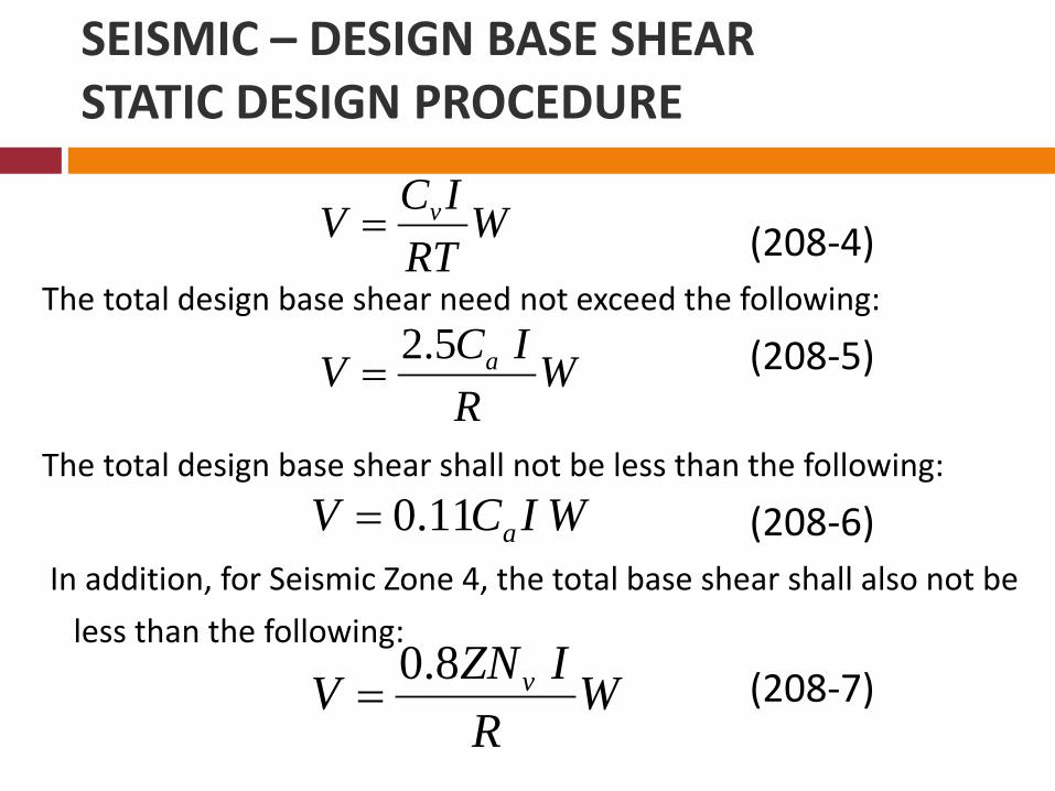
(208-4)The total design base shear need not exceed the following:
(208-5)
The total design base shear shall not be less than the following:
(208-6)In addition, for Seismic Zone 4, the total base shear shall also not be
less than the following:
(208-7)
WRT
ICV v=
WR
ICV a 5.2=
WICV a 11.0=
WR
IZNV v 8.0=
SEISMIC – DESIGN BASE SHEARSTATIC DESIGN PROCEDURE
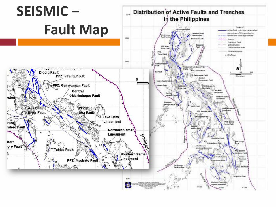
SEISMIC –Fault Map

SEISMIC ZONE
Zone 2, Z= 0.2Palawan, Tawi-
Tawi, Sulu
Zone 4, Z = 0.4Rest of the
Philippines

OccupancyCategory 1
SeismicIMPORTANCE
Factor, I
SeismicImportance 2
Factor, Ip
I. Essential Facilities3 1.25 1.50
II. Hazardous Facilities 1.25 1.50
III. Special Occupancy Structures4
1.00 1.00
IV. Standard Occupancy Structures4
1.00 1.00
V. Miscellaneous structures 1.00 1.00
OccupancyCategory 1
Seismic Importance
Factor, I
SeismicImportance 2
Factor, IpI. Essential Facilities
3 1.50 1.50
II. Hazardous Facilities 1.25 1.50
III. Special Occupancy Structures 4 1.00 1.00
IV. Standard Occupancy Structures 4
1.00 1.00
V. Miscellaneous structures 1.00 1.00
Seismic Importance Factor for Essential Structures is increased.
NSCP 2001 NSCP 2010
SEISMIC – Importance Factor, Iw

SEISMIC – Seismic Source Type

SEISMIC – Near Source Factor, Na , Nv

SEISMIC – Seismic Coefficients, Ca , Cv

SEISMIC – Structural Systems, R

30 m
Ground
6 m
Ct = 0.0853 for steel SMRF
T = Ct(hn)3/4
= 0.0853(30)3/4
= 1.093 sec
SEISMIC – Building Period, T
Ct = 0.0731 for concrete SMRF
T = Ct(hn)3/4
= 0.0731(30)3/4
= 0.937 sec

NSCP Seismic Lateral ForcesStatic Analysis Design Base Shear
25m
Given:Zone 4, Z = 0.4Seismic Source Type = ADistance to seismic source = 10 kmSoil Profile Type = ScI = 1.0R = 8.5W = 7300 kN

Determine the structure period T using Method A.For concrete moment –resisting frames, Ct is 0.0731
T = Ct(hn)3/4
= 0.0731(25)3/4
= 0.81 sec.
Find near source factors Na and Nv from Tables 208-4 and 208-5 for Seismic Source Type A and distance to seismic source of 10 km.
Na = 1.0Nv = 1.2
NSCP Seismic Lateral ForcesStatic Analysis Design Base Shear
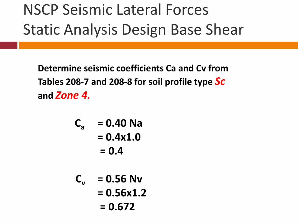
Determine seismic coefficients Ca and Cv from Tables 208-7 and 208-8 for soil profile type Sc and Zone 4.
Ca = 0.40 Na = 0.4x1.0 = 0.4
Cv = 0.56 Nv = 0.56x1.2 = 0.672
NSCP Seismic Lateral ForcesStatic Analysis Design Base Shear

Determine the Base Shear:The total design base shear in a given direction is:
V = CVI/RT x W (NSCP Equation 208-4)
= 0.672(1.0)/(8.5x.81) x 7300= 712 kN
But the code indicates that the total design base shearneed not exceed the following:
V = 2.5(CaI)/R x W (NSCP Equation 208-5)
= 2.5(0.40)1.0/8.5 x 7300
= 858 kN
NSCP Seismic Lateral ForcesStatic Analysis Design Base Shear

And that the base shear shall not be less than the following:V = 0.11CaIW (NSCP Equation 208-6)
= 0.11(0.40)(1.0)(7300)= 321 kN
And in Seismic Zone 4, the total design base shear shall also benot less than:
V = 0.8NvI/R x W (NSCP Equation 208-7)
= 0.8(0.40)(1.20)(1.0)/8.5 x 7300= 330 kN
Therefore, the governing base shear, V= 712 kN, governs.
NSCP Seismic Lateral ForcesStatic Analysis Design Base Shear

NSCP Seismic Lateral ForcesDynamic Analysis – Design Response Spectra
OTHER LOADS – RAIN LOADS
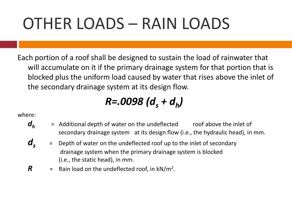
Each portion of a roof shall be designed to sustain the load of rainwater that will accumulate on it if the primary drainage system for that portion that is blocked plus the uniform load caused by water that rises above the inlet of the secondary drainage system at its design flow.
R=.0098 (ds + dh)where:
dh = Additional depth of water on the undeflected roof above the inlet of secondary drainage system at its design flow (i.e., the hydraulic head), in mm.
ds = Depth of water on the undeflected roof up to the inlet of secondary drainage system when the primary drainage system is blocked
(i.e., the static head), in mm.R = Rain load on the undeflected roof, in kN/m2.

LOAD COMBINATIONS
Buildings, towers and other vertical structures and all portions thereof shall be designed to resist the load combinations in NSCP Section 203.3 and 203.4.
The critical effect can occur when one or more of the contributing loads are not acting.

LOAD Definitions
D = dead load E = earthquake load set forth in Section 208.5.1.1 Em = estimated maximum earthquake force that can be
developed in the structure as set forthin Section 208.5.1.1
F = load due to fluids with well-defined pressures and maximum heights
H = load due to lateral pressure of soil and water in soil L = live load, except roof live load, including any permitted
live load reduction Lr = roof live load, including any permitted live load reduction

R = rain load on the undeflected roof T = self-straining force and effects arising from contraction
or expansion resulting from temperature change, shrinkage, moisture change, creep in component materials, movement due to differential settlement, or combinations thereof
W = load due to wind pressure
LOAD COMBINATIONS - Definitions

Load Combinations for RC Design and Steel Design U = 1.4 (D + F) U = 1.2 (D+ F+T ) + 1.6 (L+H) + 0.5(Lr or R) U = 1.2 D + 1.6 (Lr or R) + (f1L or 0.80 W) U = 1.2 D + 1.6 W + f1 L +0.5 (Lr or R) U = 1.2 D + 1.0 E+ f1 L U = 0.9 D + 1.6 W + 1.6 H U = 0.9 D + 1.0 E + 1.6 H
f1 = 1.0 for floors in places of public assembly, for live loads in excess of 4.8 kPa, and for garage live load
= 0.5 for other live loads

Load Combination for Strength Design
Application of the strength design load combinations that involve the seismic load E for the moment resisting frame
Z = 0.4Ca = 0.44
I = 1.0ρ = 1.1f1 = 0.5

Beam A-B and Column C-D are elements of the special moment-resisting frame. Structural analysis has provided the following individual beam moments at A, and the column axial loads and moments at C due to dead load, office building live load, and lateral seismic forces.
Dead Load D Live Load L Lateral Seismic Load Eh
Beam Moment at A 135 kN-m 65 kN-m 165 kN-m
Column C-D axial load 400 kN 180 kN 490 kN
Column Moment at C 55 kN-m 30 kN-m 220 kN-m
PROBLEM : Find the strength design moment at beam end A and strength design axial load and moment at column top C.
Load Combination for Strength Design

Load Combination for Strength Design
Strength design moment at beam end A.Determine earthquake load E:The earthquake load E consists of two components as shown below in equation (208-1). Eh is
due to horizontal forces, and Ev is due to vertical forces.
E = ρEh + Ev (Section 208-1)
The moment due to vertical earthquake forces is calculated
Ev = 0.5CaID = 0.5(0.44)(1.0)(135) = 29.7 kN-mThe moment due to horizontal earthquake forces is given as
Eh = 165 kN-mTherefore
E = ρEh + Ev = 1.1(165)+29.7 = 211 kN-m

U = 1.4 (D + F) = 1.4D U = 1.2 (D+ F+T ) + 1.6 (L+H) + 0.5(Lr or R) = 1.2D + 1.6L U = 1.2 D + 1.6 (Lr or R) + (f1L or 0.80 W) = 1.2D + 0.5L U = 1.2 D + 1.6 W + f1 L +0.5 (Lr or R) = 1.2D +0.5L U = 1.2 D + 1.0 E+ f1 L = 1.2D + 1.0E + 0.5L U = 0.9 D + 1.6 W + 1.6 H = 0.9D U = 0.9 D + 1.0 E + 1.6 H = 0.9D +1.0E
Load Combination for Strength Design

Load Combination for Strength Design
Apply earthquake load combinationsThe basic load combinations for strength design (or LRFD) are given in Section 203.3.1. For this
example, the applicable equations are:
1.2D + 1.0E + f1L (Section 203-5)0.9D ± 1.0E (Section 203-6)
Using Equation (203-5) and Equation (203-6), the strength design moment at A for combined dead, live, and seismic forces are determined.
MA = 1.2MD +1.0ME + f1ML
= 1.2(135)+1.0(211)+0.5(65) = 406 kN-m
Load Combination for Strength Design
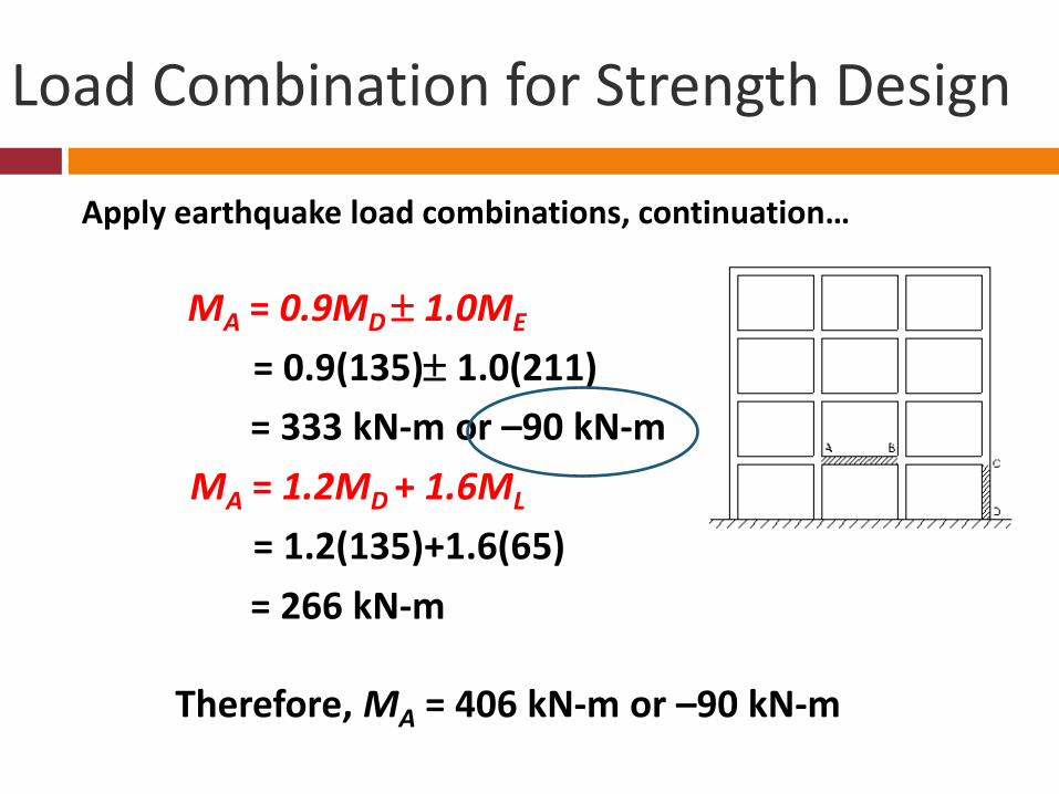
Apply earthquake load combinations, continuation…
MA = 0.9MD ± 1.0ME
= 0.9(135)± 1.0(211) = 333 kN-m or –90 kN-m
MA = 1.2MD + 1.6ML
= 1.2(135)+1.6(65) = 266 kN-m
Therefore, MA = 406 kN-m or –90 kN-m

Strength design axial load and moment at column top C.Determine Earthquake load E:
E = ρEh + Evwhere
Ev = 0.5CaID = 0.22Dfor axial load
E = ρEh + Ev = 1.1(490)+0.22(400) = 627 kNfor moment
E = ρEh + Ev = 1.1(220)+0.22(55) = 254 kN
Load Combination for Strength Design

Apply Earthquake Load combinations:
1.2D + 1.0E + f1L (Section 203-5)0.9D ± 1.0E (Section 203-6)
Design axial force Pc at point C is calculated as
Pc = 1.2D + 1.0E + f1L = 1.2(400)+1.0(627)+0.5(180) = 1197 kN
Load Combination for Strength Design

Apply Earthquake Load combinations, continued
1.2D + 1.0E + f1L (Section 203-5)0.9D ± 1.0E (Section 203-6)
Design axial force Pc at point C is calculated as
Pc = 0.9D ± 1.0E = 0.9(400) ± 1.0(627) = 987 kN-m or -267 kN
Therefore, Pc = 1197 kN or –267 kN
Load Combination for Strength Design
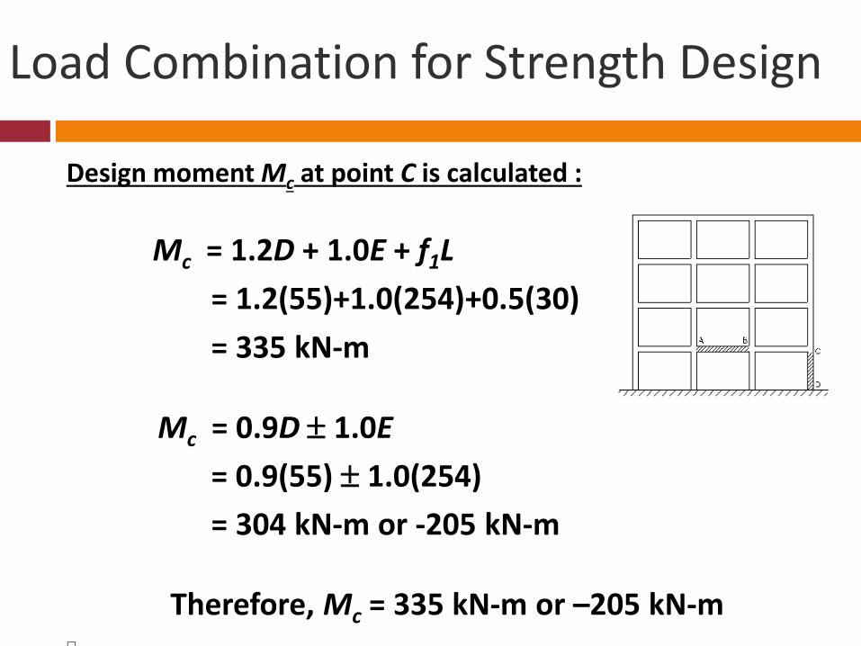
Design moment Mc at point C is calculated :
Mc = 1.2D + 1.0E + f1L = 1.2(55)+1.0(254)+0.5(30) = 335 kN-m
Mc = 0.9D ± 1.0E= 0.9(55) ± 1.0(254) = 304 kN-m or -205 kN-m
Therefore, Mc = 335 kN-m or –205 kN-m
Load Combination for Strength Design

Design moment Mc at point C is calculated , continued
Note that the column section capacity must be designed for the interaction of Pc = 1197 kN compression and Mc = 335 kN-m (for dead, live and earthquake), and the interaction of Pc = 267 kN tension and Mc = -205 kN-m (for dead and earthquake).
Load Combination for Strength Design

Important Notes
Increase in Importance Factor for Essential Facilities
Consideration of Rain Loads Totally revised Load Combinations Earthquake loading includes load effect of vertical
component of ground motion, Ev

THANK YOU