loadmaxx installation guide...note: when installing this kit on a three axle trailer, the first...
TRANSCRIPT

1PN 901-0161-000 R1
Air-Weigh Customer Support: 888-459-3247
LoadMaxxInstallation Guide
For Trailers with Mechanical Suspensions

2
Table of ContentsAbout LoadMaxx for Mechanical Suspensions.....................................1 Installation Overview..............................................................................1 Tools Required........................................................................................2Mounting the Scale...................................................................................3 Mounting Flush to the Trailer................................................................4 Mounting with a Van Bracket................................................................5 Mounting with a Frame Rail Bracket...................................................6Connecting Power to the Scale...............................................................7 Advanced Communication Add-On - ComLink Cable......................7 LoadMaxx Power Cable and ComLink Installation Guide...............8 Connecting Power with the ABS Connector......................................9
Connecting Power to the Junction Box.............................................10Welding the Deflection Sensor Brackets..............................................11Installing the Deflection Sensors...........................................................13 Installing the Trailer’s Front Axle Sensor...........................................13 Routing the Front Sensor Extension Cable......................................14 Setting the A/D Values.........................................................................15 A/D Reading is Below 750...................................................17 A/D Reading is Above 1250.................................................18 Final Sensor Torque..............................................................18 Installing the Rear Trailer Axle Sensor..............................................19 Routing the Rear Sensor Extension Cable.......................................18 Setting the A/D Values........................................................................20 A/D Reading is Below 750..................................................21 A/D Reading is Above 1250................................................2 Final Sensor Torque..............................................................21Reading and Adjusting the A/D Values................................................21Trailer Axle Finishing Touches..............................................................23 Limited Warranty.....................................................................................24Procedure for Warranty Claims.............................................................25

1
About LoadMaxx for Mechanical SuspensionsLoadMaxx for mechanical suspensions accurately measures real-time on-the-ground weights. The leaf spring scale is currently designed for tandem and tri-axle trailers. LoadMaxx for mechanical suspensions includes an icon-based touch screen display; built-in LED alarm lights; PIN protected calibration; and English, Spanish, German and French language options.Adding the optional ComLink cable (P/N 1295) to the trailer scale enables drivers to view steer, drive, trailer, GVW, and net payload on any LoadMaxx equipped tractor. Trailer scale kits can be purchased with ComLink cable included, or it is available as a simple plug-and-play option after installation.
Installation OverviewThere are five major components of the LoadMaxx scale that you will install:
• Trailer scale display• Power interface and extension cables• Sensor interface and extension cables• Deflection sensors • Brackets
Note: When installing this kit on a three axle trailer, the first sensor is to be installed on the forward facing side of the center axle and the second sensor is to be installed on the forward facing side of the rear axle.
Before calibrating, note that there is a required break-in period. First verify that your A/D readings are set in the required range. See Setting the A/D Values, starting on page 15, for more information.
2
Tools RequiredYou will need the following tools to install the trailer scale and deflection sensors:
• Standard wrench set or adjustable wrench• Drill with ¼-inch drill bit, or larger if flush mounted• Flush wire cutter• Needle nose pliers• Grinder• Chalk or permanent marker• MIG or ARC welder• Torque wrench• 22mm socket• Enamel spray paint, any color• Tape measure• C -clamps (2)
Optional Tool• Deflection sensor test box, p/n 1001
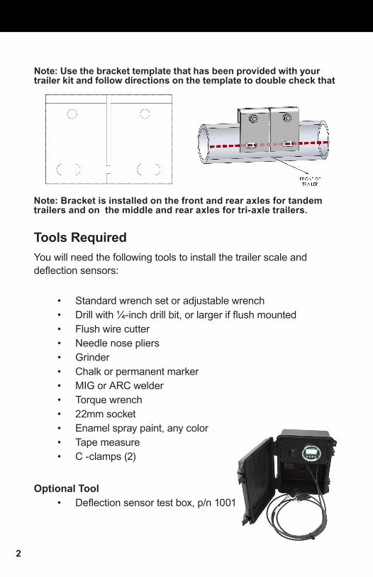
Note: Use the bracket template that has been provided with your trailer kit and follow directions on the template to double check that
Note: Bracket is installed on the front and rear axles for tandem trailers and on the middle and rear axles for tri-axle trailers.
3
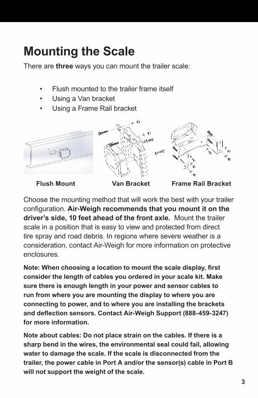
Mounting the ScaleThere are three ways you can mount the trailer scale:
• Flush mounted to the trailer frame itself• Using a Van bracket • Using a Frame Rail bracket
Flush Mount Van Bracket Frame Rail Bracket
Choose the mounting method that will work the best with your trailer configuration. Air-Weigh recommends that you mount it on the driver’s side, 10 feet ahead of the front axle. Mount the trailer scale in a position that is easy to view and protected from direct tire spray and road debris. In regions where severe weather is a consideration, contact Air-Weigh for more information on protective enclosures.
Note: When choosing a location to mount the scale display, first consider the length of cables you ordered in your scale kit. Make sure there is enough length in your power and sensor cables to run from where you are mounting the display to where you are connecting to power, and to where you are installing the brackets and deflection sensors. Contact Air-Weigh Support (888-459-3247) for more information.
Note about cables: Do not place strain on the cables. If there is a sharp bend in the wires, the environmental seal could fail, allowing water to damage the scale. If the scale is disconnected from the trailer, the power cable in Port A and/or the sensor(s) cable in Port B will not support the weight of the scale.

4
Mounting Flush to the TrailerA flush mounted scale is mounted directly to the side of the trailer.
1. Determine the best location to mount the scale. This should be a flat area of the trailer, thin enough to make drilling possible and accessible from both front and back. Make sure the back side of the location is free of obstacles and debris that would interfere with the installation.
2. Hold the scale in the location you will mount it. You can either choose to mount the scale low enough so that the port connections fit below the edge of the trailer (Air-Weigh recommends this option, if possible), or drill a hole large enough to fit the two port connections.
3. Mark the trailer surface that touches each of the screw holes in the back of the scale. If you choose to drill a hole to fit the port connections, mark a circle on the trailer surface around the two ports.
4. Drill two 1/4-inch holes into the surface of the trailer where you previously marked two screw holes. If you marked an area for the two ports, drill a hole into the surface of the trailer large enough to accommodate the two ports.
At this point, determine whether you want to connect the power and sensor interface cables to the display before or after you secure it to the trailer. If after, proceed to step 8 before completing steps 5, 6 and 7.
5. Feed the power and sensor interface cables to the back of the trailer display from below the edge of the trailer or through the previously drilled hole.
6. Plug the power interface cable into Port A at back of scale.7. Plug the sensor interface cable into Port B at back of scale.8. Place the scale over the space you have prepared on the
trailer, making sure the two holes line up with the holes on the back of the scale casing. Use the provided bolts, nuts and washers to secure the scale to the side of the trailer. Do not overtighten mounting bolts. Torque to 5 ft lbs or 6.8 Nm.

5
Van Mounting Bracket
The Van bracket is used mainly for van and refrigerated-type trailers. However, this bracket can be used on any surface-mounted installation.
1. Determine the best location to mount the scale. The bracket screws should be mounted on a ledge, and the scale itself should hang off the ledge with no obstacles blocking it.
2. Hold the bracket in the location you will mount it. Mark the trailer surface that is visible through the holes in the top of the bracket using a permanent marker.
3. Using the marked areas as a guide, drill two 1/4-inch holes into the surface of the trailer.
4. Secure the scale to the bracket. Insert one bolt and washer through each of the holes in the trailer casing and tighten.
At this point, determine whether you want to connect the power and sensor interface cables to the display before or after you secure the bracket to the trailer. If after, proceed to step 8 before completing steps 5, 6 and 7.
5. Feed the power and sensor interface cables to the back of the trailer display.
6. Plug the power interface cable into Port A at back of scale.7. Plug the sensor interface cable into Port B at back of scale.
Mounting with a Van Bracket

6
8. Secure the bracket to the trailer surface. Insert a bolt through each of the holes in the bracket and through the holes you drilled in the trailer surface. Secure in back using the supplied nuts. Do not overtighten mounting bolts. Torque to 5 ft lbs or 6.8 Nm.
Mounting With a Frame Rail Bracket
A Frame Rail bracket is used primarily for lowboy or flatbed-style trailers. However, you can use this bracket on any trailer frame rail.
1. Determine the best location to mount the scale on the frame rail. The location should be easily visible while loading and protected from direct tire spray.
2. Hold the bracket in the location you will mount it. Mark the surface of the frame rail that is visible through the four holes in the sides of the bracket using a permanent marker.
3. Using the marked areas as a guide, drill four 1/4-inch holes into the surface of the frame rail.
4. Secure the scale to the bracket. Insert one bolt and washer through each of the holes in the trailer casing and tighten.
At this point, determine whether you want to connect the power and sensor interface cables to the display before or after you secure the bracket to the trailer. If after, proceed to step 8 before completing steps 5, 6 and 7.
Frame Rail Mounting Bracket

7
5. Feed the power and sensor interface cables to the back of the trailer display.
6. Plug the power interface cable into Port A at back of scale.7. Plug the sensor interface cable into Port B at back of scale.8. To secure the bracket to the frame rail, insert a bolt through
each bracket hole and then insert those bolts through the drilled frame rail holes. Secure in back using the supplied nuts. Do not overtighten mounting bolts. Torque to 5 ft lbs or 6.8 Nm.
Connecting Power to the ScaleYou can connect the LoadMaxx trailer scale to the trailer’s power either through the ABS brake harness or directly through the lighting harness or a junction box. Both methods are equally effective regardless of your trailer setup; choose the method that is most convenient. Refer to the cable installation guide on page 8 for detailed instructions.
Advanced Communication Add-On - ComLink CableIf you have purchased the ComLink cable for your trailer scale, this is the point where you will install it. Please follow the Optional ComLink Cable Install instructions found on page 8.

8
Load
Max
x Po
wer
Cab
le a
nd C
omLi
nk In
stal
latio
n G
uide

9
Connecting Power with the ABS Connector
North American trailer manufacturers use one of two standard connectors to connect the trailer’s wiring harness to the ABS brake system: USA Brand, which uses a 6-pin plug, or Sealco, which uses a 5-pin plug. Air-Weigh provides T-breakout connectors that do not require splicing or soldering and do not interrupt power to the ABS system for each of these connector types. When you order your LoadMaxx trailer kit you must specify which type of connector your trailer uses.
1. Locate the ABS system harness. Trace the harness to the breakout connection.
2. Disconnect the 5- or 6-pin breakout connection. 3. Connect the supplied ABS T-breakout connector to both
ends of the ABS harness breakout. Make sure the locking tabs are locked securely. If you are using the USA connector, make sure all pins are properly aligned and the white plug is firmly seated in its locking hole. Failure to do so will cause faults in your ABS system.
4. Connect the scale’s power extension cable to the T-breakout connector.
5. Route the power extension cable along the frame of the trailer toward the location where the scale is installed. If possible, route along an existing wiring harness. If the trailer
Connecting the T-Breakout to the Power Cable

10
has a sliding suspension you must use an existing wiring harness or umbilical to avoid damaging or breaking the cable.
6. Secure the cable loosely to the frame using zip ties 7. Connect the end of the power extension cable to the power
interface cable. Make sure the cable is under no strain and is not bent.
-OR-
Connecting Power to a Junction BoxIf you plan to power your scale through a junction box, order the kit with a blunt cut power cable. If you ordered a cable with a connector, you can use wire cutters to cut off the connector before connecting to the junction box.
1. Starting at the 7-way connector at the front of the trailer, follow the wiring harness until you reach/find the junction box. Remove the cover of the junction box to expose the wiring. Find the blue ABS power wire.
2. Using the supplied ring terminals, connect the blue power wire on the end of the trailer scale power cable to the blue ABS wire in the junction box. Connect the white ground wire on the end of the scale power cable to the white ground wire in the junction box.
3. Route the power extension cable along the frame of the trailer toward the location where the scale is installed. If possible, route along an existing wiring harness. If the trailer has a sliding suspension you must use an existing wiring harness or umbilical to avoid damaging or breaking the cable.
4. Secure the cable loosely to the frame using zip ties.5. Connect the end of the power extension cable to the power
interface cable. Make sure the cable is under no strain and is not bent.

11
Welding the Deflection Sensor BracketsNote: Air-Weigh takes no responsibility for damage or failure of the steer axle due to improper welding or failure to follow these instructions.
1. Find and mark the center of the trailer axle(s), front and rear for tandems or middle and rear for tri-axles, on the forward facing surface(s).
2. Hold the bracket assembly on the forward side of the trailer axle centered on the mark. Use C-clamps to hold it in place.
Orient the bracket vertically as shown

12
3. Using a permanent marker, mark the inside circumference of the bracket slots on the axle.
6. Using a MIG or ARC welder, tack-weld the left and right ends of each slot and then weld the entire length of the slot. Do not weld in any other location.
7. Repeat steps 1-5 for the other axle.8. When the welds are completely cooled, remove the
C-clamps.
Fix bracket to axle with a clamp so that center of weld slot sits over the horizontal center line
Align the center slot of the bracket with the vertical line
Tack weld at these 4 locations After tack welding, make a 1/4 fillet weld around the entire perimeter of both slots
4. Remove the C-clamp and bracket. Remove the paint on the axles to bare metal where indicated by the marker. Make sure there is no paint remaining where the bracket will be welded.
5. Replace the bracket over the sanded area and secure it in place with C-clamps.

13
Installing the Deflection Sensors
Installing the Trailer’s Front (Tandem) or Middle (Tri-axle) Axle SensorNote: This installation will use the SHORTER sensor extension cable. You can determine the cable length by the middle four digits of the part number on the cable (ex: 2500 = 25 feet).
1. The two bolts, nuts and washers will be used to install the deflection sensor.
2. Insert the deflection sensor into the sensor bracket with the engraved lettering facing up and its cable extending toward the side of the trailer where you will route the SHORTER sensor extension cable from the trailer scale display.
3. Insert both bolts through the bracket holes with the keeper.4. Apply Loctite, included in your kit, to the threads. Place a
washer and a nut at the end of each bolt and hand tighten the nut.
Note About Loctite: The set time for Loctite is about 10 minutes and the cure time is 24 hours. For this reason, complete the front/middle axle sensor installation process, cable routing, and A/D value adjustments before installing the rear axle sensor and its cables.
Trailer Axle Sensor Installation

14
Routing the Front (Tandem) or Middle (Tri-axle) Axle Sensor Extension Cable
1. Starting at the trailer display, connect the SHORTER sensor extension cable to connector A on the sensor interface cable.
2. Route the SHORTER sensor extension cable along the frame of the trailer toward the location where the sensor bracket is installed. If possible, route along an existing wiring harness. If the trailer has a sliding suspension you must use an existing wiring harness or umbilical to avoid damaging or breaking the cable.
3. Secure the cable loosely to the frame using zip ties
Note: Make sure there is enough slack in the sensor extension cable to allow for axle movement. Do not tighten or trim zip ties until the full installation is complete.
4. Connect the end of the sensor extension cable to the connector on the deflection sensor. Make sure the cable is under no strain and is not bent.
Assembling the Sensor Connector

15
Setting the A/D ValuesAt this point, you have installed the trailer’s front axle sensor and routed its extension cable. You will next adjust the deflection sensor to read weight correctly by setting the A/D values. A/D refers to the analog-to-digital conversion of the sensor reading. This step will require the use of either the LoadMaxx trailer display or the Deflection Sensor Test box (P/N 1001). If using the Deflection Sensor Test box, connect the Deflection Sensor Test box to the deflection sensor connector plug and skip to the Adjusting the A/D Readings section on the following page.
If using the LoadMaxx trailer display, the scale must be installed and powered, and the Deflection Sensor Extension Cable must be installed. For instructions on how to view the sensor readings on the trailer scale display, refer to the Reading and Adjusting the A/D Values section on page 16.
1. Ensure that the deflection sensor connector is plugged into the sensor extension cable that has been routed from the trailer display.
2. Ensure the locking tabs on the connector plug engage completely.
3. Tighten both nuts on the sensor bracket using a torque wrench. Torque to 60 ft-lbs.
4. Verify the A/D reading using the trailer scale display, or the deflection sensor test box. If the reading is within range (750-1250), continue to instructions for the Final Sensor Torque. If the reading is not within range, follow the instructions to adjust the A/D readings on the following pages.

16
DIAGNOSTICS
TYPEMODEL #SERIAL #SOFTWARE
EXT SENSOR6040400-40014V2.00
SENSOR
EXT A 860 OKEXT B 920 OKPORT 1 N/APORT 2 N/A
From the main screen, select the wrench icon to enter the Settings menu.
Select the medical bag icon to enter the Diagnostic menu.
Select the down arrow.
This screen will show both the A and B sensors.
Reading and Adjusting the A/D Values During diagnostics steps, 2 sensors should appear on the screen. If not, refer to Calibrating with the Set-Up Wizard in the user manual (p. 4), or call customer support for assistance For a full description of how to operate your trailer scale, please refer to the user guide included in your kit.

17
Adjusting the A/D ReadingIf the A/D reading is above 1250, follow these instructions:Note: When tightening the bolts, ALWAYS torque the nut, NOT the bolt head. The bolt head should be in the bolt head holder, which is built into the bracket.
1. Loosen the nuts on both ends of the sensor bracket.2. At the plastic nut where the cable enters the deflection
sensor, exert DOWNWARD pressure with your fingers until the A/D reading is between 750 and 1250. Continue to apply pressure to maintain the desired A/D reading during the torque procedures in step 3.
3. Tighten the nut on the sensor bracket where the cable end exits and torque to 60 ft/lbs. Continue to apply pressure with your finger to the plastic nut during torquing in order to maintain the desired A/D reading. If the A/D readings are still within the 750 to 1250 range after the nuts on both sides of the sensor bracket have been torqued to 60 ft/lbs, continue to instructions for the Final Sensor Torque.

18
If the A/D reading is below 750, or there is no A/D reading at all, follow the steps below:
1. Loosen the nuts on both ends of the sensor bracket.2. At the plastic nut where the cable enters the deflection
sensor, exert UPWARD pressure with your fingers until the A/D reading is between 750 and 1250. Continue to apply pressure to maintain the desired A/D reading during the torque procedures in step 3.
3. Tighten the nut on the sensor bracket where the cable end exits and torque to 60 ft/lbs. Continue to apply pressure with your finger to the plastic nut during torquing in order to maintain the desired A/D reading. If the A/D readings are still within the 750 to 1250 range after the nuts on both sides of the sensor bracket have been torqued to 60 ft/lbs, continue to instructions for the Final Sensor Torque
Final Sensor Torque
1. Torque both nuts to 120 ft/lbs.2. Perform a final check to A/D values using the readings from
the trailer scale display, not from the A/D Box. If A/D readings are not within range, repeat the Adjusting the A/D reading steps.
19
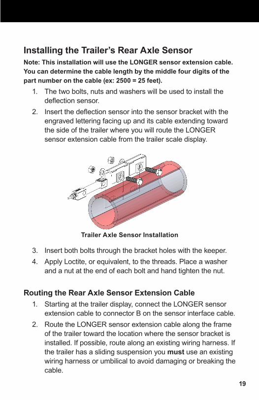
Installing the Trailer’s Rear Axle SensorNote: This installation will use the LONGER sensor extension cable. You can determine the cable length by the middle four digits of the part number on the cable (ex: 2500 = 25 feet).
1. The two bolts, nuts and washers will be used to install the deflection sensor.
2. Insert the deflection sensor into the sensor bracket with the engraved lettering facing up and its cable extending toward the side of the trailer where you will route the LONGER sensor extension cable from the trailer scale display.
3. Insert both bolts through the bracket holes with the keeper.4. Apply Loctite, or equivalent, to the threads. Place a washer
and a nut at the end of each bolt and hand tighten the nut.
Routing the Rear Axle Sensor Extension Cable1. Starting at the trailer display, connect the LONGER sensor
extension cable to connector B on the sensor interface cable.2. Route the LONGER sensor extension cable along the frame
of the trailer toward the location where the sensor bracket is installed. If possible, route along an existing wiring harness. If the trailer has a sliding suspension you must use an existing wiring harness or umbilical to avoid damaging or breaking the cable.
Trailer Axle Sensor Installation

20
3. Secure the cable loosely to the frame using zip ties.Note: Make sure there is enough slack in the sensor extension cable to allow for axle movement. Do not tighten or trim zip ties until the full installation is complete.
4. Connect the end of the sensor extension cable to the deflection sensor connector. Make sure the cable is under no strain and is not bent.
Setting the A/D ValuesThis step will require the use of either the LoadMaxx trailer display or the Deflection Sensor Test box (P/N 1001). If using the Deflection Sensor Test box, connect the Deflection Sensor Test box to the deflection sensor connector plug and skip to the Adjusting the A/D Readings section on the following page.
If using the LoadMaxx trailer display, the scale must be installed and powered, and the Deflection Sensor Extension Cable must be installed. For instructions on how to view the sensor readings on the trailer scale display, refer to the Reading and Adjusting the A/D Values section on page 21.
1. Ensure that the deflection sensor connector is plugged into the sensor extension cable that has been routed from the trailer display.
2. Ensure the locking tabs on the connector plug engage completely.
3. Tighten both nuts on the sensor bracket using a torque wrench. Torque to 60 ft-lbs.
4. Verify the A/D reading using the trailer scale display, or the deflection sensor test box. If the reading is within range (750-1250), continue to instructions for the Final Sensor Torque. If the reading is not within range, follow the instructions to adjust the A/D readings on the following pages.

21
DIAGNOSTICS
TYPEMODEL #SERIAL #SOFTWARE
EXT SENSOR6040400-40014V2.00
SENSOR
EXT A 860 OKEXT B 920 OKPORT 1 N/APORT 2 N/A
From the main screen, select the wrench icon to enter the Settings menu.
Select the medical bag icon to enter the Diagnostic menu.
Select the down arrow.
This screen will show both the A and B sensors.
Reading and Adjusting the A/D Values During diagnostics steps, 2 sensors should appear on the screen. If not, refer to Calibrating with the Set-Up Wizard in the user manual (p. 4), or call customer support for assistance For a full description of how to operate your trailer scale, please refer to the user guide included in your kit.

22
Adjusting the A/D ReadingIf the A/D reading is above 1250, follow these instructions:
1. Loosen the nuts on both ends of the sensor bracket.2. At the plastic nut where the cable enters the deflection
sensor, exert DOWNWARD pressure with your fingers until the A/D reading is between 750 and 1250. Continue to apply pressure to maintain the desired A/D reading during the torque procedures in step 3.
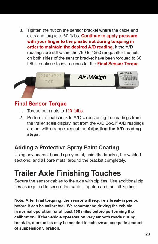
3. Tighten the nut on the sensor bracket where the cable end exits and torque to 60 ft/lbs. Continue to apply pressure with your finger to the plastic nut during torquing in order to maintain the desired A/D reading. If the A/D readings are still within the 750 to 1250 range after the nuts on both sides of the sensor bracket have been torqued to 60 ft/lbs, continue to instructions for the Final Sensor Torque.
If the A/D reading is below 750, or there is no A/D reading at all, follow the steps below:
1. Loosen the nuts on both ends of the sensor bracket.2. At the plastic nut where the cable enters the deflection
sensor, exert UPWARD pressure with your fingers until the A/D reading is between 750 and 1250. Continue to apply pressure to maintain the desired A/D reading during the torque procedures in step 3.
Note: When tightening the bolts, ALWAYS torque the nut, NOT the bolt head. The bolt head should be in the bolt head holder, which is built into the bracket.
23
3. Tighten the nut on the sensor bracket where the cable end exits and torque to 60 ft/lbs. Continue to apply pressure with your finger to the plastic nut during torquing in order to maintain the desired A/D reading. If the A/D readings are still within the 750 to 1250 range after the nuts on both sides of the sensor bracket have been torqued to 60 ft/lbs, continue to instructions for the Final Sensor Torque
Final Sensor Torque1. Torque both nuts to 120 ft/lbs.2. Perform a final check to A/D values using the readings from
the trailer scale display, not from the A/D Box. If A/D readings are not within range, repeat the Adjusting the A/D reading steps.
Adding a Protective Spray Paint CoatingUsing any enamel-based spray paint, paint the bracket, the welded sections, and all bare metal around the bracket completely.
Trailer Axle Finishing TouchesSecure the sensor cables to the axle with zip ties. Use additional zip ties as required to secure the cable. Tighten and trim all zip ties.
Note: After final torquing, the sensor will require a break-in period before it can be calibrated. We recommend driving the vehicle in normal operation for at least 100 miles before performing the calibration. If the vehicle operates on very smooth roads during break-in, more miles may be needed to achieve an adequate amount of suspension vibration.

24
Limited WarrantyFor product failures due to material or manufacturing defects, Air-Weigh will replace or repair all components for up to 3 years from shipment date to the end-user Air-Weigh customer. These three-year components include: Displays, ComLinks, Sensors, Power Cables, Sensor Assemblies, Sensor Harnesses, and all other associated external components. Air-Weigh assumes no responsibility for administering warranty claims directly with any third party end users.
The responsibility of Air-Weigh under this warranty is limited to the repair, replacement, or credit of the defective part or assembly.
This warranty does not cover incidental or consequential damage to persons or property caused by use, abuse, misuse, or failure to comply with installation or operating instructions. This limited warranty does not apply to any product that has failed due to accident, abuse, alteration, installation not consistent with printed installation instructions, improper maintenance, improper operation, or as a result of system integration or installation not explicitly approved in writing by Air-Weigh.
Air-Weigh and its resellers shall have no responsibility or liability for damages if the purchaser or any other person alters the vehicle incorporating Air-Weigh products. This limited warranty shall not apply to any product that has been repaired or altered by anyone not employed by Air-Weigh or not operated in accordance with the manufacturer’s printed material delivered with this product.
Air-Weigh hereby expressly disclaims any and all implied warranties of any type, kind of nature whatsoever, and particularly any implied warranty of merchantability or fitness for a particular purpose not expressly stated by Air-Weigh in its printed material delivered with its products.
Some states do not allow the exclusion or limitation of incidental or consequential damages. If such laws apply, the limitations or exclusions contained in the terms and conditions of this Warranty may not apply. This warranty gives you specific legal rights and you may also have other rights, which vary state to state.
May be covered by U.S. Patent Nos. 5478974, 5780782, 7478001Foreign Patent Nos. 260494, 677998, 2122766
Copyright © 2004, 2006, 2007, 2010, 2011, 2012, 2013 by Hi-Tech Transport Electronics, Inc. All rights reserved. Air-Weigh®, ComLink™, and Hi-Tech Transport Electronics are
trademarks or registered trademarks of Hi-Tech Transport Electronics, Incorporated. Other brand, product, or service names listed in this document are the trademarks or registered
trademarks of their respective holders. Information contained in this literature was accurate at time of publication. Product changes may have been made after copyright dates that are
not reflected in this document.

25
Procedure For Warranty ClaimsALL customers should first contact Air-Weigh Customer Support Department at (888) 459-3247 for questions regarding the use, operation, repair or return of any Air-Weigh product.
In the event Air-Weigh requests to examine the product prior to disposition OR for repair or replacement, Air-Weigh requires a Return Material Authorization (RMA) number be issued before the item is returned. Customer Support will issue the RMA number. Please reference this RMA number in all correspondence.
Claimed items shall be shipped freight pre-paid to: Air-Weigh Customer Support Department 1730 Willow Creek Circle, Suite 100Eugene, Oregon 97402, USA
The Air-Weigh RMA number must appear on the outside of the return packaging.Air-Weigh shall examine returned material within 30 days after receipt, or sooner if mutually agreed upon. If Air-Weigh determines that the part or assembly was defective in material or workmanship and within the warranty period, Air-Weigh will repair or replace the part or assembly and return freight pre-paid. In the event Air-Weigh determines that the part or assembly cannot be repaired or replaced and is within the warranty period, a credit not to exceed the purchase price will be issued to the Air-Weigh customer.
For our customers using purchase orders Air-Weigh will process a credit memo and notify the customer by email or fax. The customer will process a corresponding debit memo and notify Air-Weigh accordingly.
If the part or assembly received by Air-Weigh does meet the requirements of the warranty program set forth above, at the Air-Weigh customer’s request the part or assembly will either be discarded, returned freight collect, or repaired or replaced at Air-Weigh customer’s expense and returned freight collect.

26
1730 Willow Creek Circle • Eugene, OR 97402-9152 USAP.O. Box 24308 • Eugene, OR 97402-0437 USA
Telephone (541) 343-7884 • Order Desk (888) 459-3444Customer Support (888) 459-3247 • Fax (541) 431-3121
www.Air-Weigh.com