loading rifle user ‘s manual l+. - textfiles.compdf.textfiles.com/manuals/firearms/fn_fn49.pdf1st....
TRANSCRIPT
F.N. SELF
USER l+.
MODEL 49 - LOADING RIFLE ‘S MANUAL
Fabrique NatIonale d’Armes de Ciuerre Socktc Anonyme
HERSAL- LEZ - LIEGE (BELGWM)


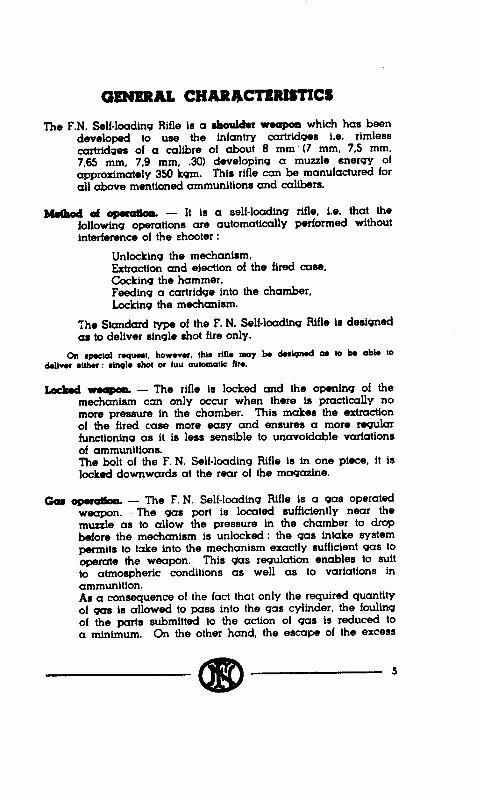


HOW THE P. N. SELF-LOADING RIFG WORKS
The gun being ready for firing the action on the trigger releases the hammer. Under the tension of its springs, the hammer strikes the firing pin, which in turn strikes the primer of the cartridge and ignites the powder charge.
1st. phase. - Tho bolt opoam uador the actton oi the gas.
A small amount of gas escapes through a port bored in the bai rel and passes in the gas cylinder where it kicks the piston back. The piston drives the bolt carrier back. The bolt carrier unlocks the bolt and pulls it upwards to the rear. The extractor, which fits to the bolt, draws the empty shell out of the chamber. When the empty case is completely disengaged from the chamber its bottom strikes the ejector which ejects it to the right out of the gun. In its backward motion the bolt carrier cocks the hammer and compresses the recoil springs.
2d. phase - The bolt ir cl04 uador the ton&n d rocotl sprbqm.
As for any weapon firing with closed bolt, as soon as the bolt carrier has completed its backward motion, the recoil springs drive it forward. The bolt carrier itself forces the bolt forward. The bolt drives a cartridge ahead out of the ma9azine and pushes it into the chamber. The bolt is then locked downwards in the receiver by the action of the bolt carrier.
DRAILS OF OPERATION
1. THE ENGINE
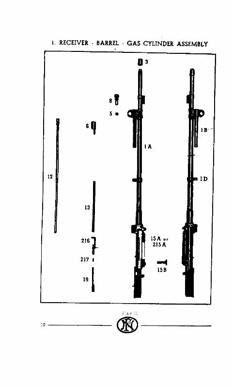
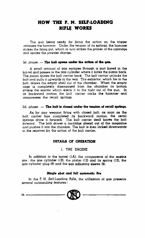
In addition to the barrel (lA), the components of the en9ine are : the gas cylinder (1Bl. the piston (121 and its sprin9 (13, the gas cylinder plug (81 and the gas adjusting sleeve (61.
Stnqlo rhot md full automattc ftm
In the F. N. Self-Loading Rifle, the utilization of gas presents several outstanding features :
24 @
Fiq. I.
a) Short gas cyhcler. - The 9as cylinder (IB) is a very short tubular element, easily cleaned, after the gas cylinder plug and the piston have been removed. As experience has shown that the gas acted on the piston in the way of a hammer blow, without any expanding, the ions cylinders which were generally, used in gas operated rifles, have consequently become useless.
b) Gas escape. - After they have acted hi the way of a blow on the piston, the gas escape outside throu9h a slot (Al located on top of the front end of the 9as cylinder.
The handicap of. the 9as operated weapons betn9 the foulin9, the advantage of this 9as escape system is the permanent sweepin outwards of the combustion residues.
c) Gas regulatioa. - The size of the slot for the escape of gas and its location are such, that when it is completely open the pressure exerted by the gas on the piston is insufficient to operate the mechanism. That is the point where the regulator intervenes. The regulator is built from a simple’threaded sleeve (6). screwed around the gas cylinder. When the sleeve is screwed in, the openins for gas escape decreases and consequently the thrust of the gas on the piston is growinq, a 9ood functtonin9 of the rifle, without undue fati9ue for the mechanism, is thus ensured. The gas regulation is carried out by the manufacturer, when the rifle is assembled. It may not be changed by the soldier. The regu- lator has therefore been intentionally located under the hand9uard. On the other hand, it is a very easy task for the armourer to refix the 90s regulation if. eventually, another resulation has to be adooted. either in order to use a lot of soecial ammunition. or to use-the rifle in a country in completely different
which the atmospheric conditions are
2s
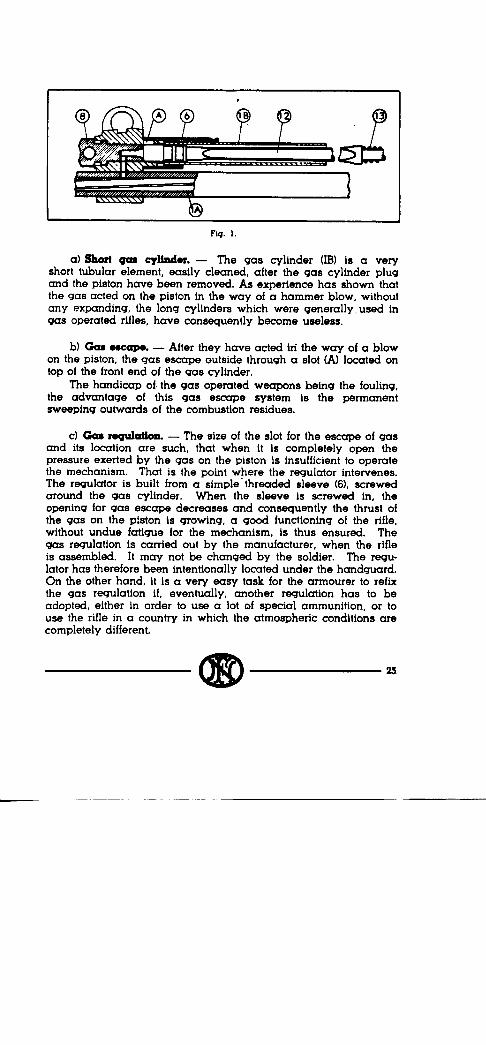
d) Iodm of the pbton. - The piston (12) and the bolt carrier (27) are located in a-straight line, without any COtUl8CtiOn.
The return of the piston is performed instantly under the action of its own spring (13) without the interference of the return springs. It is owing to this original feature that it is possible to load the gun the same way as a repeatinb rifle.
Turning 18(r the qas cylinder plug (8A1, cuts the inlet of the
gas. The piston does not transmit any thrust on the bolt carrier. The rifle can then be used like a repeater by pulling 6’18 bolt carrier by hand.
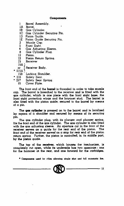
2. HOW THE OPENING AND THE CLOSING OF THE MECHANISM IS OPERATED
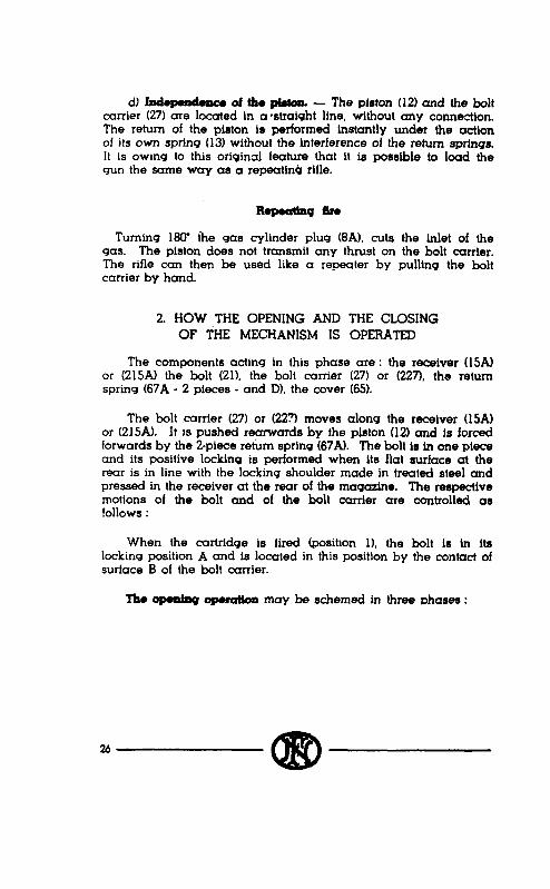
The components acting in this phase are : the receiver USAl or (215Al the bolt (21). the bolt carrier (271 or (227), the return spring (67A - 2 pieces - and DI, the cover (651.
The bolt carrier (271 or (223 moves along the receiver USA) or (215A). It is pushed rearwards by the piston (12) and is forced forwards by the P-piece return spring (67A). Th8 bolt is in one piece and its positive locking is performed when its flat surface at the rear is in line with the locking shoulder mad8 in treated steel and pressed in the receiver at the rear of th8 magasine. The respective motions of the bolt and of the bolt carrier are controlled as !ollows :
When the cartridge is fired fposition 11, the bolt is in its locking position A and is located in this position by the contact of surface B of the bolt carrier.
n8-m may b8 schemed in three phases :
26 a!D
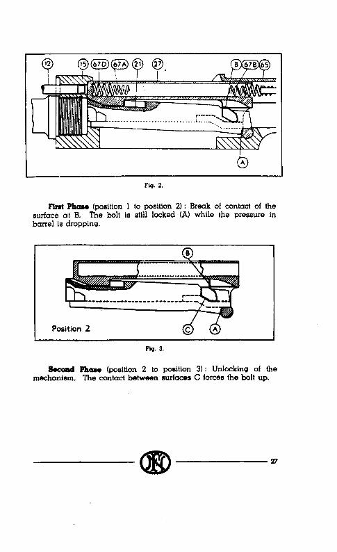
Fig. 2.
First Phase (position 1 to position ‘2) : Break of contact of the surface at B. The bolt is still locked (A) while the pressure in barrel is dropping.
F&J. 3.
Suomd b (position 2 to position 3) : Unlocking of the mechanism. The contact between surfaces C forces the bolt up.
a!D 27

Position 3
Flq. 4.
‘IMrd Phase (position 3 to position 4): Direct opentnq. The bolt and the bolt carrier are travellinq together rearwards owinq to the contact of surfaces F.
When the parts are stopped at the rear, they are in position 4, the double return spring is compressed.
Flq. 5.
The cl- of the me&w may be schemed as below in 3 phases :
Fowth phase (position 4’to position 5)‘: Clorinq of the mecha- nism. The bolt carrier pushes the bolt forwards owing to the contact of surfaces G till the bolt is rtopped by rear end of the barrel.
28
0

Position 5
Fh. 6.
FWh Phase (position 5 to position 6) : L.ockinq of the mecha- nism. At this moment the slope H forces the rear part of the bolt downwards, in the lockinq position.
Position 6
Flq. 7.
Sixth m (position 6 to position 1). Confirmation of the lockhq. The bolt carrier continues its movement forward and the bolt is maintained in the locking position by the surfaces B.
The repeatinq cycle is identical with the automatic cycle. k;trnaz receive the thrust d the piston, the bolt carrier is operuted
a!D 29

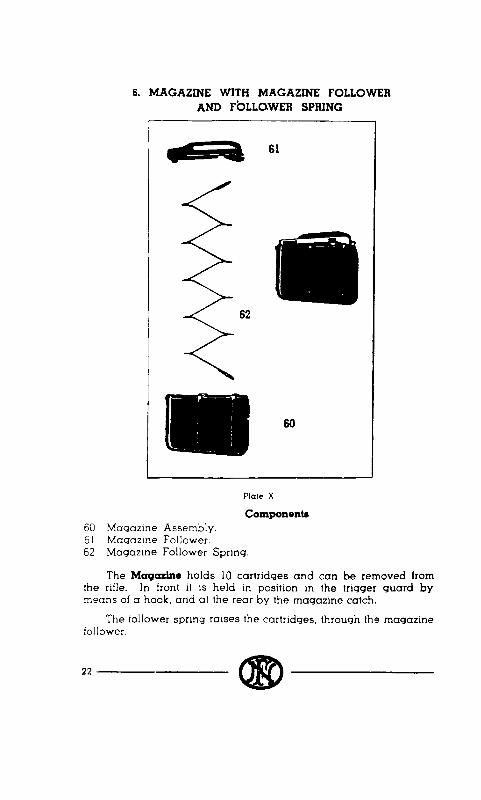
3. FEEDING - EXTRACTION - EJECTION
The additional parts actin@ in this phase are : the (22) and the elector (51).
extractor
a) B&action of the case. - The extractor which is . fitted on the right side of the bolt performs this operation by direct extraction for the wlthdrdwal of the case (see above : 3d phase - posittin 3 to position 4).
b) Ejociioa - The ejector is of the fixed type and is fitted in the trigger quard at the rear of the magazine. It protudes in a groove cut at the left and in the underside of the bolt. At the end oi the rearward motion (3d phase). the case strikes against the ejector and being compelled to pivot around the extractor is ejected riqhtwards.
lhere exist other types of ejectors but the type choosen for the F. N. rifle has the great advantage to help the shooter to know how his rifle is working, as the ejection occurs nearly at the end of the travel of the bolt to the rear at the moment when its is at the point to b3 stopped against the rear wall of the receiver,
. . .
‘1
<‘- A. ‘V’ / 1,
K.,’ \
” “.\ 22 ‘\.@ 0 $ 51
Fig. 8.
A violent ejection shows that the recoil motion develops at a too great velocity and with a needless violenae to perform the functioning, with the consequence that the wear and tear of the mechanism is amplified. Thanks to the regulator, it is then
30 (li!D
very eaa to ensure, with a thorough knowledge of the where- abouts a perfect functioning of the rifle.
With electors which are fitted elastically on the receiver this cannot be reached.
c) lntroductlon of a cart&go. - The bolt has two ribs on its lower side, these ribs, when the bolt is closing (see above 4th phase, - position 4 to position 5) push alternatively the left or the right side cartridge directly into the chamber.
As soon as the cartridge leaves the lips of the magazine, it is caught by the extractor and moves with the bolt. This charac- teristic, taken from the best repeaters, presents several advantages :
1. The double feeding is impossible ;
2. The extractor is spared, because it has not to 90 over the rim of the cartridge as it is the case when the cartridge is first introduced into the chamber.
3. The closing is smoother. It ought to be mentioned that the closing is only due to the energy stored during the recoil in the springs and not to a positive mechanical action.
4. HOW THE FIRING ACTION WORKS
For rifles firing only single shot, the firing action is fitted in the trigger guard (301 and consists of :
- The hammer (31Al with its springs (34A-Bl and its guide (31Bl which serves also as a cocking indicator.
- The trigger (36) which serves as the principal sear.
- The rear hook acting as the auxiliary sear (391.
- The safety (46).
The firing of the cartridge occurs by means of a firins pin (in two parts) (24-281 housed in the bolt.
The characteristics of the mechanism are as follows :
aD 31

J
Fw 9 Fiq. 10.
Action of rifle ftrt.119 only stn910 shot fire.
a) Sopcuotion of the shots iu stn910 shot ftro. - The device which allows to fire exclusively shot by shot, has been taken over from an outstandmg weapon (The Browning automatic shotgun). Since more than 50 years It ensures a perfect functioning to this popular gun.
The hammer (31A) is forced backwards by the recoil of the bolt and bolt carrier and it is in any case caught by the double hook, which is made up by the front end of the trigger acting as the main sear (36) and by the linked hook acting as the auxiliary sear (39).
Indeed 11. per chance, owing to the effect of the recoil the fmger of the shooter has left the trigger at the moment the hammer 1s sent backwards, the hammer is directly caught by the main sear (36). If on the contrary, which is generally the case, the trigger 1s still depressed by the finger, the hammer is caught by the auxiliary sear (39) which has been put on its way by the motion of the trigger. The hammer is caught in this position as long as the trigger 1s depressed. In order to fire the next shot one has first to release the trigger. - The hammer is then released by the auxi- liary sear (39) but is at once and uncrvoidably caught by the r -in sear (36). To fire again one has to depress the trigger once more.
32 CID

Flq. 11 Fig. 12.
Action of rlflo !irinq rIaq10 rhot and full automatic 5m
For rifles ahIs !o shoot either sin+ ahot or full automatic fire. the foUowinq parts are designed as to deliver this kind of firing. their item number are then as follows : Auxiliary sear (39) superseded by auxiliary sear (239) :. Hammer (31 A) superseded by hammw (231 A) ; Rmiver body (15A) superwded by receiver body (215A) : Bolt carrier (27) superseded by bolt carrier (227); Triqqer ward (30) superseded by trtqqer quard (230); Stock (65A) superseded by stock (265A).
Further on the Iollowinq parts arm used : Safely sear (216A); Safety soar sprinq (217); Automatic fire Iwor (232).
SW thow compononta on Lip. I1 and 12 as well a* the sectional view of weapon at the end ol this pamphlet.
It ought furthermore to be noticed that :
1” The weapon being on safety, with the trigger locked, the cocking of the rifle by hand is possible owing to the oval slot (A) of the hammer, which is consequently able to move longitudinally.
2” If the finger depresses the trigger at the moment the hammer returns backwards any shock to the finger is prevented owing to the elasticity of the linkage of the auxiliary sear.
bl Double pull. - This is the result of the action of the auxiliary sear spring which resting against the trigger cooperates with the trigger spring and gives the shooter the feeling of a l double pull s motion.
aiD 33
c) Cocking iadkutor. - As the hammer is completely concealed U-I the weapon, it is desirable that there should be a way to make sure externa!ly.if the rifle IS ready or not for action. To this end, the guide (31B) of the hammer spring protrudes beneath the trigger guard when the hammer is cocked. It is thus easy, even m the dark, to make sure by mere feeling if the hammer is cocked or not.
d) !Safoty. - The safety (46) is located on the side of the trigger guard, it is consequently very easily acceSsible and is easily actuated without removing the hand from the butt.
As the angle between the positions l Fire l and . Safety s is important, the safety is easily felt in the dark and even visible from a certain distance.
The arm of the safety is fitted, inwardly, with a spring plunger which fixes it in the selected position. In the l safety l position, the safety worjcs like a skid against the trigger in such a way that the more the action on the trigger is sharp, the more the safety is confirmed.
In a rifle equiped for lull automatic fir*. the workinq of tha action 11 different lrom that 01 the single ahot lire in the following points :
Aa the automatic Iir~.Iww (232) Is located In th* posltion . A l : the cylin- d&al ,XXt of the lever bcdy Is in contact with the icmq of lb auxiliary sear (239) and prevents the sear lo pivot Iorward when the triqqer II depressed. The enqaqement 01 the hammor (231A) by the auxiliary soar II conuquentl,y impos- sible when the triqqer is depressed. In other worda, thr auxiliary sear (239) Is switched out and does not mlorlere any more in the action.
On the other hand, aa low aa the triqqw is depressed. the main sear bolnq no more In tha way of the hammer (231): this ia not catchd aflw each shot. The bmxn soar ia however superseded by the safety ~ear (216) whose rear end penetrates a qroova in the hammer and keeps it at the rear until the bolttarrior comes tack to its forward ,:~siMon. The safety war is than pushed loword by the belt-carrier and its sprinq (217) compressed. Th. hammer is then fin to b flung forward unaer the a:tlon of its sprinqs (34-A-B).
When the triqqor is r&awd, the main war. whkh b one ploco with the triqqor, h aqaln in the way of the hammer mrd catch- the hammer norwards, s:opplnq con~equ.ntly th. firinq.
5. LOADING
The reloading of the rifle as it is designed with its piston on top of the barrel, is possible owing to :
1’ The independence of the piston and of the bolt carrier, which enables the piston to move back to its locatfon under. the

action of its own spring as soon as it has thrown the bolt carrier rear-wards.
2” The action of the holding open’device which holds the bolt and bolt carrier to the rear.
Flq. 13.
This device (43A) consists of a plunger located vertically at the rear of the magazine and in front of the bolt when the bolt is in its full rearward position. The spring of this plunger, keeps the plunger downward, in its housing 1 ‘&he trigger guard, and consequently out of the functioning of the weapon as long as there are cartridges in the magazine. When the last cartridge has been fired and the bolt has travelled to the rear, the magazine platform rear end engages the front end of the bolt stop, lifting the stop in front of the bolt and preventing it to return in the closing position. The shooter is consequently warned that the magazine of his rifle is empty.
As the piston has returned to its forward position and as the bolt is held to the rear, the magazine is open to be refilled. It is only necessary to insert two clips, with 5 rounds each, one after each other in the grooves out in the receiver and to press, with the thumb of the right hand, on the upper cartridge of each clip in order to introduce the 2 bundles of 5 cartridges into the magazine.
After the cartridges have been introduced into the magazine,
ai!D 35

closing the rifle only requires a short pull on the operattnq handle, so introducing a cartridge *into the chamber. Pulling of the opemting handle compels indeed the bolt to withdraw releasing the holding open device which withdraws in tts houstng under the action of its spring.
If it is desired to refill the magazine before it is empty in order to give the rifle its full potentiality of fire, the bolt carrier stop is to be used.
This stop is fitted on the left side of the cover and is perfectly accessible to the thumb of the right hand after pulling operating handle, and consequently the bolt, to the rear.
The retracting of this stop is the same as that of the automatic holding open device.
6. SAFEGUARDS
The functioning of the hand safety, which locks the trigger, has been described before.
Further, as detailed below, the rifle may be carried with 10 cartridges in the magasine, without cartridge tn the chamber. In order to be ready for firing, only pull operating handle fully rearwards and release it.
Fiq. 14.
There are two internal safeguards which make the firing impossible so long as the rifle is not duly locked.
1.’ The first of these safeguards is performed without the addi- tion of any part, it results only from the relative motions of the bolt
36 a!D

and of the bolt carrier. In fact, the hammer can only reach the firing pin when the bolt is locked and positively confirmed in this position by the complementary m*otion of the bolt-carrier.
2y The second safeguard is performed by means of a firing pin stop (26) which prevents the striker to protude in the face of the bolt so long as the locking of the rifle is not performed, as the bolt carrier prevents any motion of the firing pin stop upwards (see fig. 15). On the contrary. when the rifle is locked, the firing pin stop is allowed to raise and does no more prevent the motions of the firing pin (see fig. 16).
Fiq. 15.
Flq. 16.
aD 37
HOW TO HANDLE THE RIFLE
TO MAKE, THE GUN SAFE
With thumb of right hand, rotate safety lever downwards. In this postnon of safety lever, trigger IS posrtively locked. Moreover safe!y lever prevents the fmger of the shooter to reach the trigger. It 1s so very easy, even in the dark, to make sure that the gun is safe.
To release safety, reverse the movement of safety lever upwards, wrth index fmger of right hand.
TO OPEN AND TO CLOSE THE BOLT
To open the bolt, grasp with right hand operating handle and draw it fully back. If there are no cartridges in magazine, bolt will be held in the open position by bolt catch which, under the action of magazine platform, protrudes before the bolt.
To close the bolt, push down magazine platform with thumb of left hand, at the same time draw bolt carrier slightly back with right hand. Under the tension of its spring, bolt catch is forced down and does no more protrude n-t the path of bolt. Release gently mechanism forward, withdraw left thumb when bolt is above magazine platform.
LOADING THE RIFLE
With right hand, grasp operating handle and pull mechanism to the rear. The mechanism will be held open by the bolt catch.
Loading the gun may be carried out either by inserting single cartridges into magazine, or by means of 5 rounds clips. When the loading is completed, draw slightly back slide handle and let it go, mechanism will close forward under the thension of recoil springs, pushing a cartridge into the chamber.
The magazine holds 10 cartridges but it is not necessary to !ill it, the mechanism will close in the same way whatever the number of cartridges in magazine may be.
Jt is possible to close the mechanism without introducing a cartridge into the chamber with. the magazine loaded with 10 rounds : with right hand, grasp oroerating handle and pull it slightly back, with thumb of left hand push down cartridges of magazine and release gently the mechanism, retaining it with right hand. The mechanism will so close above the top of the cartridges in the magazine and there will be no round in the chamber. This is an original way to transport safely the loaded
38 a!D

gun. To make the weapon ready for firing, one has just to cock the mechanism to introduce a cartridge into the chamber.
If the weapon is partially unloaded, it is possible to complete the loading of the magazine : grasp operating handle with right hand, pull mechanism fully rearwards. With thumb or right hand depress bolt carrier catch and release operating handle, the bolt carrier will be held in the rear position by bolt carrier catch.
Complete the loading of magazine, pull slightly back operating handle, bolt carrier catch will release .the bolt carrier. Release operating handle, mechanism will close pushing a round into the chamber.
The possibility to load the gun either with single rounds or standard clips, and the possibility to complete the loading of magazfne are original features of the F. N. self loading rifle, in comparison to similar weapons.
Unloading the gun may be carried out in two ways : The first method is to cock the gun, without firing, with the
safety on, as many times as there are cartridges in the magazine. When the magazine is unloaded, the mechanism will be held in the rear position by bolt catch. In order to close the mechanism, with left hand, push down magazine platform, while right hand pulls operating handle slightly backwards, release gently mechanism.
The second method is a follows : release magazine by pressing with nose ofcartridge on magazine catch, while other hand gathers magazine and cartridges, cock the gun in order to eject cartridge inserted in chamber. Replace magazine.
All operations necessary for loading or unloading may be performed with gun on safety. The safety does not prevent the motion of mechanism either forwards or rear-wards.
FIRING THE RIFLE
Tg fire, put safety off, sight the rifle and depress the trigger.
With a rifle fitted lor the lull automatic shoo:inq: to shoot : Simqla d~l fh. - Put !~re lever m positnn . S. A v, put salely in the l off l
pos111on. Ssht the nlle and depress the Iflqqer. Each tnne the trigger is depressed a shot wll be hred.
Full au(omatk Iire. - With the lire lever put in position a A l , put safety . off l by turnmq safety lever Siqht the r II I e and depress the trigger. The hrinq wtl be automatically performed as Ion9 as the tr199er is depressed and as lonq there are cartndqes m the maqartne. The lirinq stops as soon as the trigger 1s released.
0 39

STRIPPING AND ASSEMBLING
L FIELD STRIPPING AND ASSEMBLING
STRIPPING THE MECHANISM
Turn receiver cover locking key 18W upwards, grasp receiver cover and slide it forward against action of recoil springs, raise shqhtly rear end of receiver cover in order to disengage cover from guides m receiver. Release cover rearward. Cover and recoil springs will so be removed from receiver. Grasp operating handle and pull back bolt carrier and bolt assembly until guides of bolt carrier are in line with clearance cut in guides of receiver. Lift front-end of bolt carrier and bolt assembly and remove bolt carrier and bolt assembly from receiver. Remove bolt from bolt carrier.
STRIPPING THE BOLT
First remove firing pin stop. Using nose of cartridge, lift extractor spring out of spring housing cut in bolt and rotate extractor spring 9W. Remove extractor. Grasp bolt at both ends between thumb and index finger. Push firing pin in bolt. Remove extractor spring, firing pin and firing pin spring. Take firing pin spring off firing pin.
REMOVING THE PISTON
Using nose of cartridge depress gas cylinder plug catch and rotate plug W’. Remove gas cylinder plug. Tilt rifle forward, piston and piston spring will slide out of gas cylinder. Remove piston spring from piston.
STRIPPING THE MAGAZINE
Using nose of cartridge, lift magazine catch and remove maqazine from trigger guard. Remove magazine platform and platform spring. Disengage magazine spring from magazine platform.
The weapon is so disassembled for complete cleaning.
ASSEMBLING THE BOLT
Replacs firing pin spring on firing pin. Replace firing Pin and firing pin spring in bolt. Depress firing pin in bolt and replace
40 a!D

extractor spring head in bolt (extractor spring being at an angle of 900 with the bolt). Release firing pin which, under the tension of firing pin spring will hold extractor spring. Replace extractor in its seat. Rotate extractor spring 90” in order to insert it in extractor seat. Replace firing pin stop.
ASSEMBLING THE MECHANISM
Replace bolt in bolt carrier. Seize bolt and bolt carrier assembly at both ends between thumb and index and replace bolt and bolt carrier assembly in receiver to enable guides of bolt to pass through clearance cut in guides of receiver. When bolt and bolt carrier assembly is home push it forwards. Grasp receiver cover, turn upwards cover locking key, insert recoil springs in hole of bolt-carrier. Compress recoil springs pushing cover forward.
Replace cover downwards in receiver, front end first, and release cover as to allow it to drop backwards fully home in its guides. Turn cover locking key downwards. Test motions of mechanism a few times by hand in order to make sure assembly is correct.
ASSEMBLING THE PISTON
Replace piston spring on piston, replace piston and piston spring in gas cylinder (head of piston turned to the muzzle). Replace gas cylinder plug, depressing plug catch, and turn plug in such a way that letter A is turned outside. Release gas cylinder plug catch.
ASSEMBLING THE MAGAZINE
Insert magazine platform spring in magazine platform. Replace magazine platform and spring in magazine, take care to replace them in correct position. Seize magazine and introduce magazine in trigger guard, engaging first front stud of magazine in recess in trigger guard. Press on magazine bottom until magazine is caught by magazine catch.
II. COMPLEYE STRIPPING AND ASSEMBLY
The rifle ought first to be stripped as described for stripping.
the field
a!D kl
COMPLETE STRIPPING OF THE RECEIVER COVER
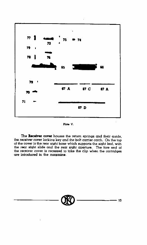
Remove the return sprmqs by disenqaqmq. with the help of a screw-driver, the first coil of the inner sprmq from the end of its rod. Separare the outer sprrnq from the inner springs and the inner sprmqs from their guide.
To strip the backsight : depress tail of sight leave in order to compress the sight spring and to disengage the leave studs from the shoulders. Draw back the sight leave and remove it from the cover. Remove the leaf spring from its housing, using the hole cut in the spring. Grasp rear of leaf in riqht hand, with the left hand grasp the siqht slide and slide lock, depress &de lock, and remove slide and slide lock from the leaf. Remove slide lock and its spring from the sight slide.
Unscrew the two lateral adjusting screws and remove rear sight aperture.
In order to strip the bolt carrier catch : with the help of the point of a bullet depress the bolt carrier catch spring, this will allow to turn the bolt carrier catch body outwards. Remove the spring, remove the catch by raising it, remove bolt carrier catch stop.
STRIPPING OF THE HANDGUARD
Unscrew front end cap screw. Remove front end cap from the front. Remove front part of handguard swinging its front end upwards.
Unscrew lower band screw which will free swivel ; lower band is so able to open. Remove lower band from the front.
Remove rear part of handguard. swinging its front end upwards.
STRIPPING THE GAS REGULATOR SLEEVE
With the handguard removed, it is only necessary to unscrew qas regulator wleeve using, if necessary, qas regulator key. Remove gas regulator sleeve.
STRIPPING THE BARREL - RECEIVER ASSEMBLY
Unscrew trigger guard stop screws, unscrew and remove trigger guard screws, the barrel-receiver assembly may thus be removed from the stock.
42 - (89
To remove cover plate, raise its front end in order to disengage it from its groove and swing the cover 90’.
In the case 01 rifles fitted for the lull autoiatic lirmq. with the barrel.receiver assembly ranowd born Iho #lock it is powblo to remc~ve the safety aoar lrom the rec~wer. Depreu a&ty sear lorwards and at the same time diwnqaqo safety sear from its housing by raisinq it. The sale~y sear and its spnnq are thus tree.
STRIPPING OF THE TRIGGER-GUARD
With the trigger guard screws and their stop screws removed, it is possible to remove the trigger guard assembly from the stock.
In order to remove the bolt stop, de- the bolt stop reIainer plunger, remove bolt stop retainer, bolt stop retainer plunger and its spring. Remove bolt stop.
In order to dismount the ejector and the magaxine catch and its spring. remove, from left to right the magaxine catch axis pin.
In order to dismount the action, let the hammer gently down, if it is cocked, remove trfgqer axis pin, remove auxiliary sear, its spring and its plunger, remove the trigqer. its spring and its plunger.
In the came of rllle fittd lot tha full automatic firlnq. rwnov~ the automatic lirq lww. lo this end. swhq II backwards vwtkally with the trlqqr quad. rwnow aulomalic flre lwer from the triqqw quad.
In order to remove the safety - after the action has been stripped - swine the safety lever in the intermediate positfon between the safety position and the fire position, remove then safety from the tdclger ward.
STRIPPING THE STOCK
To remove the various components : take out their screws.
ASSEMBLING THE STOCK
Replace the components of stock and fix them by meanx of their screws.
ASSEMBLING THE TRIGGER - GUARD
To replace the safety : replace safety axis in the trigqerquard. introducinct it from the riqht and locatinqt the safety lever in the
a!D 43
intermediaie position between l Safe l and . Off l . Depress safety spring plunger, press safety fully home.
To assemble the action ; replace trigger spring and plunger in their housing, replace the trigger in the trigger guard from the top, taking care that the stud fitted on the safety lever is engaged in the groove cut in the trigger, replace auxiliary sear spring and plunger in their housing in the auxiliary sear, replace auxiliary sear assembly into the trigger guard, the hooks. of trigger and of auxiliary sear facing each other and axis holes being in line, replace trigger axis pin.
To replace the ejector and the magazine catch : replace in its housing the magazine catch spring, replace In trigger guard magazine catch and ejector putting their pin holes In line. Replace magazine catch axis pm from rtght to left.
To replace the bolt stop, replace bolt stop h its housfng fn the trigger guard, replace bolt stop retainer plunger and rpring. replace bolt stop retainer as to engage head of bolt stop re!afner plunger into its housing cut in the bolt stop retainer.
ASSEMBLING -RECEIVER - 0ARRU. GROUP
For the rilba whkh am Ilctd Ior chs lull au,~ Llrc : replow th aaloty war rpdnq (with th. amatl co11 downwards) on the-wMy moor. Replac. aal.8~ mar qrmlp In the rodv*r mrdnq opomllon of slllppInq. mktnq can that maI l pr.nq k ptd in Its houalnq.
Put the protective cover into posftfon from the right, vertically, and give it a quarter turn clockwise.
Replace receiver and barrel in position on the stock. Replace and acrew fully fn trigger guard screwa and stop screws.
ASSEMBLING GAS REGULATOR SLEEVE
Screw regulator rleeve an gas cylinder, with thr retaining spring to the rear. Use key if necessary.
ASSEMRLING HANDGUARD
Replace handguard mar part, insertfng first its rear end into the groove cut fn the reoelvor. replace lower band and swivel,

screw in lower band screw. Replace handguard front part, insertmg first its rear end under lower band. Replace front end cap as to fix front end of handguprd and screw in front end cap screw.
ASSEMBLING THE COVER
Replace bolt carrier stop : replace bolt carrier catch stop and bolt carrier catch spring in their housing in the bolt carrier stop. Place bolt carier catch axis in its housing in the cover, at an angle of about 60”. depress bolt carrier catch stop and turn bolt carrier stop home.
To assemble the rear sight : replace sight aperture. Replace rearsight slide lock spring in sight slide. replace slide lock in sight slide taking care that the crosspieces are opposite. Depress slide lock and replace slide assembly on sear leaf taking care that the figures of the sight are turned the same side as the slide cross piece. Make sure that sliding the slide along the leaf is easy.‘ and, on the other hand, that the claw of the slide lock engages well in the notches of sight leaf when slide lock is released., Replace rear leaf spring in its housing. Replace sight leaf on the receiver (figures of leaf being turned upwards) to this end depress leaf spring and slide the studs of the leaf beneath the shoulders in rear sight base. Replace and screw in sight aperture screws.
Replace return springs : to this end place inner springs and inner spring guide in outer spring, replace the return springs assembly on the rod of cover.
GENERAL ASSEMBLY OF RIFLE
See assembly after - Field Stripping l , page 40.
RECOMMENDATIONS
1. The rifle must always be on safe during transport.
2. Working parts ought to be slightly oiled. It is however Important not to overlubrlcate when the rifle is used m a sandy country. It 1s then better to keep the gun nearly dry.
3. Make sure before firing that barrel is clean.
4. Make sure that magazine is clean and dry.
5. Make sure that magazine is fully home in trigger guard and well engaged by magazine catch.
6. Do not mtroduce by hand a cartridge in a hot barrel.
7. In case of misfire, wait a few seconds before opening the mechanism.
8. Adjustement of gas if necessary is periodically carried out by field armourer, the soldier has not to trouble about it.
9. In case of stoppage, open mechanism and hold it open by means of bolt carrier catch.
10. After daily firing, remove gas cylinder and clean it as well as piston. Make sure that piston is wel! free in gas cylitrder.
11. In order to be ready for immediate firing, the rifle muy be transported with magazine loaded with 10 rounds but with the bolt closed on empty chamber. To open fire, it is just necessary to cock the xxhunism
12. Wb the weapon is not firing, protective cover on right side of receiver ought to be pushed forward in order to avoid sand and dust to get into the mechanism.
44 CED
NUMRRICAL DATA
Weight of rifle
Weight of single
Weight of barrel
Lenght of rifle
Lenght of barrel
. . . . . . . . . . . . . . 4,300 kg
barrel ............ 0,920 kg
as&nbly .......... 1,120 kg
.............. 1,110 m
.............. 590 mm
Weight of bayonet (230 mm long) ....... 0,320 kg
Weight of baycmkt with scabbard .... : .. 0,550 kg
Weight of bayon&@ mm long). ...... 0,450 kg
Weiqht of long ksyonst with z&bard. ..... 0,700 kg

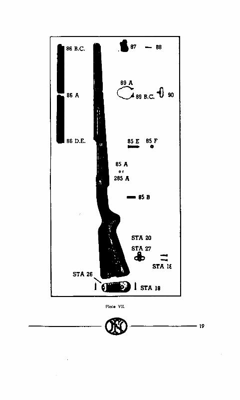
COMPONENT PARTS
N. B - l Components used for nIlis allowmq automalic
Number c! par,. NAME
1 1A 1B 1C 1D 1E
:
: 8A 8B 8C 8D
12 13 15
lSA- ‘215A 1SB
. 216A
. 216B
. 216C
. 217 19 19A 19B
;;
;:
;: 27 - l 227
28 30 - l 230
31 31A-•231A
318 31c
Barrel Assembly . . . . . . - .
IrrInq.
ouant. pm Gun.
. . -
Barrel . . . . . . . . . . 1 Gas Cylinder ........... i Gas Cylinder Securing Pin ...... 1 Piston Guide Piston Guide S&i& Pin’ : : : : : : : Muzzle Cop ............ 1 Front Siqht Gas odjustinq Sleeve : : : 1 : : : :
1 1
Gas Cylinder Plug, complete ..... - Gas Cylinder Pluq ......... Gas Cylinder Plu9 Plunqer ...... ; Gas Cylinder Plug Plunger Spring ... Gus Cylinder Pluq Plunger Washer ... : P&ton .............. Piston return Spring ......... t Receiver . . - Receiver Body .’ ’ .’ .’ .’ .’ .’ . : . . Locking Shoulder ’
1
Safety Sear (for crutomcrtic’firinq~ 1 1 1 1 f Safety Sear Spring Rest ....... Spring Rest Axis Pin ........ f Safety Sear Spring ......... 1 Cover Plate, complete - ........ Cover Plate Body ........ : 1 Cover Plate Stud ......... Bolt Extractor . : : :
......... f
......... Extractor Spring .......... ; Firing Pin - Rear End ........ Firinq Pin Spring Firinq Pin Safety Stop 1
....... :
....... Bolt Currier Firinq Pin - Front End : : : 1 : : : :
: 1
Triqer Guard ........... 1 Hammer, complete :_ ... . .. . . . - Hammer Body Hammer Sprinq Guide : : 1 : : : :
1 1
Hammer Sprfnd Guide Axtr Pin .... 1
46 aD
I) 232 * 232A 1 232B 0 232C * 232D v 232E I) 232F
::A 34B
:: 37 38
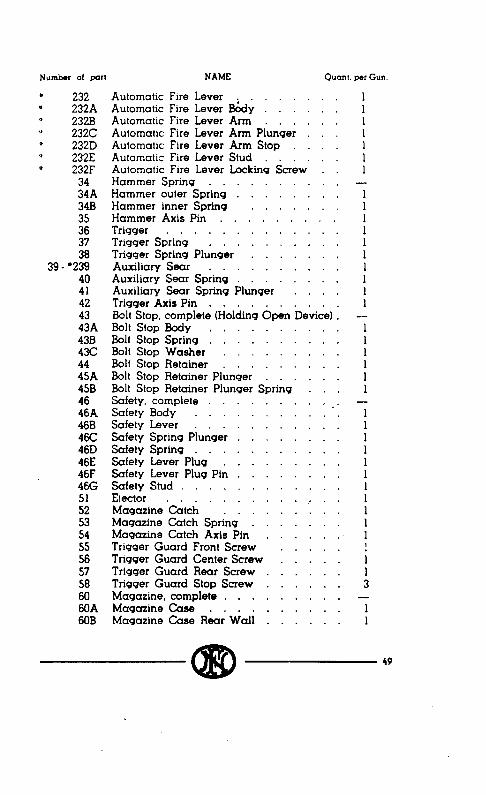
39 - l 239 40 41 42 43 43A 43B 43c 44 45A 4SB 46 46A 468 46C 46D 46E 46F 46G
2:. 53 54 55 56 57 58
::A 60B
Number of part. NAME Quant. per Gun.
Automatic Fire Lever Automatic Fire Lever B&y . : : :
1 . . 1
Automatic Fire Lever Arm . . . . . 1 Automatic Fire Lever Arm Plunger 1 Automatic Fire Lever Arm Stop . . 1 Automatic Fire Lever Stud . . . . . 1 Automatic Fire Lever Locking Screw . 1 Hammer Spring . . . . . . . . - . Hammer outer Spring . . . . . . 1 Hammer inner Spring . . Hammer Axis Pin . .’ . .’ , .’
. 1 . 1
Trigger . . . . . . . . . . . . 1 Trigger Spring . . . . . . . . . . 1 Trigger Spring Plunger . . . . . . 9 1 Auxiliary Sear . . . . . . . . . . 1 Auxiliary Sear Spring . . . . . 1 Auxiliary Sear Spring Plunger . . 1 Trigger Axis Pin . . . . . . . 1 Bolt Stop, complete (Holding Open Devi IceI . -- Bolt stop Body . . . . . . . . . . 1 Bolt Stop Spring . . . . . . . 1 Bolt Stop Washer . . . .
. . Bolt Stop Retainer . . . . : Bolt Stop Retainer Plunger . . . . . 1 Bolt Stop Retainer Plunger Spring . . . 1 Safety, complete . . . - Safety Body
_. 1
Safety Lever . . . . . . . 1 Safety Spring Plunger . . . . . . 1 Safety Spring . . . . . . . . . 1 Safety Lever Plu9 Safety Lever Plug Pin 1 1 1 1 1 1
. . 1
. 1 Safety Stud . . . . . . . 1 Ejector Maqaxine ‘Catch 1 : : 1 1 1 1
. 1
. . Magazine Cutch Spring . . . . . : Magazine Catch Axis Pin . . . . 1 Trigger Guard Front Screw . . . . . Trigger Guard Center Screw . . . . . i Trigger Guard Rear Screw . . . . Trigger Guard Stop Screw . . . . . . ; Magazine. complete . . . . . . . . . - Maqazine Case Magazine Case R& &Ii : : : :
. . 1 . 1
k9

Numtmr 01 pd. NAME Ouont. par Gun.
60C 60D 60E 6OF 60G 60H
:;
:;
66A 66B 66D 66E 66F 66G
:;A 67C 67D 70 i0A 708 7oc 71 72 73 74 75 76
zl 79
85A - “2::A 85B 85E 85F
::A 86B 86C 86D
Maqazine Case Luq . . . . . . . 1 Cartridge Frdnt Guide . . . . . . . 1 Maqazine Catch Hook . . . . . . Magazine Rivet, lonq . . . . . . i Magazine Rivet, short . . . . . 2 Magazine Catch Hook Rivet . . . . 2 Magazine Platform . . . . . 1 Magazine Platform Spring . . . . . 1 Receiver Cover . . . . . . . . . 1 Return Spring Guide and Cover Lockinq
Key, complete . . . . . *. . . . - Return Spring Guide . . . . . . . 1 Cover Locking Key Cover Locking Key Plunqer 1 1 : : :
1 1
Cover Lockinq Key Plunqer Washer . Cover Lockinq Key Cup
1
Cover Locking Key Cap Washer ’ : : : 1 1
Return Springs. complete with Guide . . - lnner Return Spring . . . . . . . . 2 Inner Return Springs Guide . . . . . 1 Outer Return Spring . . . . . . . . 1 Bolt Carrier Catch, complete . . . . . - Bolt Carrier Catch Bady ‘. . . . . * 1 Bolt Carrier Catch Head . . . . . . . 1 Bolt Carrier Catch Washer . . . . . Bolt Carrier Catch Stop . . . . b . . f Bolt Carrier Catch Spring . . . . . . Rear Siqht Leaf . . . . . . . . i Rear Siqht Aperture . . . . . . . 1 Rear Siqht Aperture Adiustinq Screw . 2 Rear Siqht Leaf Sprinq . . . . . . . 1 Rear Sight Slide Rear Siqht Slide Lock ’ : : : : : : : t Rear Siqht Slide Lock Sprinq . . . . . 1 Stock . . . . . . . . . . . . . - Stock Body . . . . . . . . . . . 1 Trigger Guard Rear Screw Bushinq . . . Recoil Luq . . . . . . . . . . . . : Recoil Luq Nut . . . . . . . . . . i Handquard. complete . . . . . . . - Handquard Body (2 pieces) . . . . . . Handquard Front Cap . . . . Handquard Front Cap Rivet ’ . . . . .
: 2
Handquard Rear Cap . . . . . . * 1
so aD

86E 87 87A 87B 88
:A
g
LZA STA.27
STZ STA.19 STA.28 STA.26
93 93A
S7A.F 501
Handguard Rear Cap Rivet ...... Front End Cup - assembly ...... Front End Cup Body Front End Cap Bushing’
.......
....... Front End Cup Screw ....... Lower Band assembly ....... LowerBandBody ......... LowerBandScrew ......... Lower Band Screw Retaining Screw ... Swivel, complete .......... Swivel support .......... Swivel ..... Swivel Ptn 1 1 1 1 1 1 .
.
Swivel Base and Butt Plate Screw .... ....
Swivel Base Pin ......... Swivel Base Butt Plate, Standard’ T& ............ Sling. complete .......... Sling Leather ........... Sling Buckle ........... Sltnq Button . . Gas Regulator i<e); 1 1 1 1 1 1 1 . .
BAYONET
Blade .............. Handle CrosaGu~ : : : : : : : : : : * Plunqer- Catch ........... Stock _& ..................... :
scabhardsprtn9.. . tsmbbad sprincJ screw Scabbard Hook . . . scabbard Collar Sc&bard Button . . . . Plunger Catch Nut . . Stock Screw . . . . Washer HandleG : : : 1 : CrossGuardPtn . . . Plunger Catch Spring .
.......
.......
.......
. . . . . . .
2 -
1
f
7 1 1
7 2 1 4
1 1
r 1 1 1
I
:
: 1 1 1 1 1
........ ....... t ....... 2 ....... ....... 2” ....... 2 ....... 1

Numbor of pm. NAME aant. per Gun.
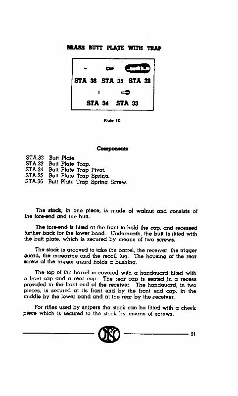
BBAssBurrPLATEwKlfTMP
STA.32 Butt Plate . . . . . . . . . . . ST-A.33 Butt Plate Trap
Butt Plate Trap P&t’ : 1 : : : : : : t
STA.34 STA.35 Butt Plate Trap Spring f STA.36 Butt Plate Trap Sprinq SC;& : : : : : 1
STA.51 Butt Plate 1 STA.52 Butt Plate Trap ’ : : : : : : : : : : STA.53 Butt Plate Trap Pivot . . . . . . i STA.54 Butt Plate Trap Plunger’ : . . . . . . STA.55 Butt Plate Trap Sprint . . . . . . . :
Ac6msoBEsToBBsuPPLleDo11sPBuAL =aJ=T
2 Muzzle Brake
2 BIank Firing Attachment Barrel Cleaner
STAT Cleaner Case
STA:45 Earrel Cleaning Brush Chamber Clexxning Bru8h
52 ,f’I!!D


F.N. SELF
USER l+.
MODEL 49 - LOADING RIFLE ‘S MANUAL
Fabrique NatIonale d’Armes de Ciuerre Socktc Anonyme
HERSAL- LEZ - LIEGE (BELGWM)