load-sense control valve...load-sense control valve pc25 /pc55 series 6 parker hannifin corporation...
TRANSCRIPT

Load-Sense Control ValvePC25™/PC55™ Series
2 Parker Hannifin CorporationHydraulic Valve DivisionHicksville, Ohio, USA
RefuseAutomated vehicles requirethe performance of load-sensepressure-compensated valves.Our Flow-Sharing featureensures that cycles are neverinterrupted when the engineis run at idle (a pump overdemand condition).
The Parker HannifinHydraulic Valve DivisionAssures:
ConstructionMachines requiring highproductivity benefit with load-independent metering. OurFlow-Sharing feature enablesthe operator to maintain therhythm of the machine duringpump over demand conditions.
ForestryThe responsiveness and theFlow-Sharing feature of thePC25 and PC55 valves makethem particularly well suited tothe productivity and reliabilityrequirements and demandsof harvesting and loadingequipment.
Snow & IceThe inherent excellentperformance of load-sensepressure-compensatedvalves assures load indepen-dent control. Flow-Sharingaddresses and resolves theproblems associated with the“dead stick” phenomenon.
Parker's technical resources provide thetechnologies needed to fulfill your productrequirements. That's why thousands ofmanufacturers and equipment users aroundthe world rely on Parker products and people.
Performance of the PC25 and PC55 isoptimized when matched with Parker's newP2/P3 piston pumps and the bypass unloadersproduced by the Gear Pump Division.
� Consistent quality
� Technical innovation
� Premier customer service
FAILURE OR IMPROPER SELECTION OR IMPROPER USE OF THE PRODUCTS AND/OR SYSTEMS DESCRIBED HEREIN OR RELATED ITEMS CAN CAUSE DEATH,PERSONAL INJURY AND PROPERTY DAMAGE.
This document and other information from Parker Hannifin Corporation, its subsidiaries and authorized distributors provide product and/or system options for further investigation byusers having technical expertise. It is important that you analyze all aspects of your application and review the information concerning the product or system in the current productcatalog. Due to the variety of operating conditions and applications for these products or systems, the user, through its own analysis and testing, is solely responsible for making thefinal selection of the products and systems and assuring that all performance, safety and warning requirements of the application are met.
The products described herein, including without limitation, product features, specifications, designs, availability and pricing, are subject to change by Parker Hannifin Corporationand its subsidiaries at any time without notice.
WARNING
The items described in this document are hereby offered for sale by Parker Hannifin Corporation, its subsidiaries or its authorized distributors. This offer and its acceptance are governedby the provisions stated in the "Offer of Sale".
Copyright 2001, 2002, Parker Hannifin Corporation, All Rights Reserved
Offer of Sale
II

Load-Sense Control ValvePC25™/PC55™ Series
3 Parker Hannifin CorporationHydraulic Valve DivisionHicksville, Ohio, USA
IndexGeneral Info ........................................................................ 3Introduction ........................................................................ 4Product Matrix ................................................................... 5PC25 Spool Positioning Options ................................... 6-7Description of Operation .................................................. 8PC25 Performance Curves ........................................... 9-10PC25 Installation Drawing .............................................. 11PC25 Coding ................................................................ 12-15PC25 Specification Questions ........................................ 16PC25 Spec Sheet .............................................................. 17PC55 Performance Curves ......................................... 18-19PC55 Installation Drawing .............................................. 20PC55 Coding ................................................................ 21-23PC55 Specification Questions ........................................ 24PC55 Spec Sheet .............................................................. 25Offer of Sale ...................................................................... 26
These are the main advantages of load-sensing pres-sure-compensated valves that positively impacts theperformance of your machine.
• metering is independent of load. Changes inpressure due to load variation do not affect theoutput flow of the valve. This provides predictablespeed control and makes the operator’s job easier.
• simultaneous metering is generally unaffected bychanges in pressure due to load changes. There-fore, the operator does not waste time throttling flowto two functions with changes in load. This improvesproductivity and reduces operator fatigue.
• lower flow forces translate into lighter lever efforts.For manually operated valves, this reduces operatorfatigue.
• flow forces within the valve are more linear vs. spoolstroke, resulting in lower hysterisis for pilot-operatedcontrol valves. This improves the predictability ofactuator speed vs. operator command.
• horsepower consumption is optimized wheninterfaced with a piston pump, because only theflow requested by the valve is delivered.
General IntroductionAs an overview, load sensing or flow on demandsystems employ a variable or fixed displacement pump.A piston pump will have a load-sense control mountedonto the pump that regulates the flow to the controlvalve by positioning the swashplate. The control mecha-nism is usually adjustable from 200-300 psi (14-20 bar).It will compare the pressure at the outlet of the pump tothe load-sense pressure signal coming from the valveand will increase or decrease flow until it reachesequilibrium. Equilibrium is reached when the pressuredifferential between the outlet of the pump and load-sense signal of the valve reaches a pre-determinedvalue referred to as margin pressure.
When a gear pump is used with a bypass unloader, thefunction of the unloader is similar to the load-sensecontrol mechanism on the piston pump. The unloadersenses the pressure at the output of the pump vs. theload-sense signal from the control valve. It’s function isto regulate flow to the valve until the flow requirementsas defined by the spool notch opening are met. Excessflow, however, is unloaded to tank at a pressure slightlyhigher than the operating pressure of the valve.
When the metering notches of the control valve spoolare opened slightly, it does not take much flow to satisfythe margin pressure requirement. If the valve spool isstroked farther, the load-sense control on the pump willsense a drop in pressure and will bring the pump onstroke until the margin pressure requirement is satisfied.If the stroke of the spool is reduced, the load-sensecontrol will sense an increase in pressure differentialand will de-stroke the pump until the new flow require-ment is met.
PC55™
PC25™
Load-Sense Control ValvePC25™/PC55™ Series
4 Parker Hannifin CorporationHydraulic Valve DivisionHicksville, Ohio, USA
Product Availability• Clipper relief valves in inlets.
• PC25 inlet has option for integrated pressure-reducing valve to support Electro-Hydraulicoperation.
• PC55 inlet with a bypass unloader.
• Work-Sections (3) position, (4) position float and(4) position regeneration.
• Spool Positioners - spring-return, three positiondetent, spring-return/detent, pneumatic, on/off andproportional solenoid and hydraulic-remote. Strokelimiters available with hyraulic-remote and solenoidcaps.
• Port Accessories - relief valves, lockout reliefvalves, relief valves/anti-cav’s, anti-cav’s, unloadingvalves and port restrictors.
• Full flow and limited flow spools
• PC25 porting (max):- Inlet – SAE 16- Section – SAE 12- Outlet – SAE 20
• PC55 porting (max):- Inlet – SAE 20- Section – SAE 16- Outlet – SAE 24
SpecificationsNominal Flow Ratings:
PC25 - 45 gpm (170 lpm)
PC55 – 70 gpm (265 lpm)
Operating Pressure - 4000 psi (275 bar)
Exhaust Pressure - 300 psi (21 bar)
Margin Pressure - 250 psi (17bar) - recommended
Filtration Required (nominal) - ISO 18/14
Fluid - Mineral Based Hydraulic Oil
Fluid Temperature and Viscosity Range -20 to 200 F (-29 C to 150 C)
Number of Work-Sections -10
Weight lbs. (approximate):
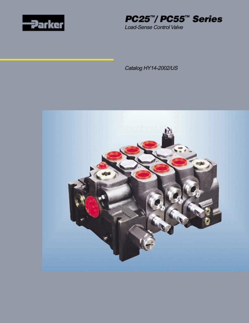
IntroductionPC25 4000 psi (275 bar),
45 gpm (170 lpm) nominalPC55 4000 psi (275 bar),
70 gpm nominal (265 lpm)
The PC25 and PC55 are load-sense pressure-compen-sated valves.They employ contemporary technologywhich assures that the selected functions get flowduring a pump overdemand conditon. This flow-sharingprinciple is generally instrumental in improving machineproductivity.
The PC25 and PC55 also have a patented, dual-checkarrangement. This was designed to improve valveresponse and the efficiency of the section compensator.
Key Features of PC25™ and PC55™:• Flow Sharing principle responds to pump-
overdemand, by reducing flow to the selectedfunctions - while maintaining the speed relationshipbetween those functions.
• Its patented dual-check system ensures that aclean, crisp load-sense signal is sent to the pump.This makes for a very responsive machine, even incold weather.
• Compensator efficiency is excellent. This meansthat the selected flow does not, generally, vary withchanges in load.
• The compensator can efficiently process flows atleast equal to the maximum rated flow of the valve.
• Can accommodate induced loads.
• Symmetrical work-section housing enables thespool to be inserted into either end of the spoolbore.
• Uses the same port accessories and spoolpositioners as their open-center counterparts.
PC25 PC55Inlet with rv 16 25Outlet 15 23Work-Section - manual 14 19 - hydralic remote 16 24 - solenoid 22 30
Load-Sense Control ValvePC25™/PC55™ Series
5 Parker Hannifin CorporationHydraulic Valve DivisionHicksville, Ohio, USA
Flow (gpm) Max. PC25 PC55GPM/LPM 45/170 70/265PSI/BAR 4000/275 4000/265Maximum PortingInlet SAE 16 SAE 20Work Section SAE 12 SAE 16Outlet SAE 20 SAE 24
Equivalent BSP & Metric Porting AvailableSAE 8, M18SAE 10, BSP 1/2, M22SAE 12, BSP 3/4, M26SAE 16, BSP 1, M33SAE 20, BSP 1 1/4, M42SAE 24, BSP 1 1/2, M48
CircuitryParallel Yes Yes(4) Position Float Yes Yes(4) Position Regeneration Yes Yes
Spools AvailableDouble Acting Cylinder Yes YesDouble Acting Motor Yes YesSingle Acting Cylinder @ Port B Yes YesSingle Acting Motor @ Port B Yes YesDouble Acting Cylinder, 4th Position Float Yes YesDouble Acting Cylinder, 4th Position Regen. Yes Yes
Symmetrical Work Section Housing
BackupsSpring Return Yes Yes(3) Position Detent Yes YesDetent Spool In, Spring Return Spool Out Yes NoDetent Spool Out, Spring Return Spool In Yes NoSpring Return with 4th Position Detent Yes NoElectro Magentic Detent Yes NoPneumatic, Single Ended Yes YesHydraulic Remote (Metered & On/Off) Yes Yes Stroke Limiters for Hydraulic Remote Yes YesHydraulic Remote (Metered with 4th Position Float) Yes YesHydraulic Remote (Metered with 4th Position Regen.) Yes YesSolenoid (On/Off & Proportional), Double Ended Yes Yes Stroke Limiters for Solenoid operation Yes Yes
Port AccessoriesR/V (Shim Adjustable) Yes YesR/V (Screw Adjustable) Yes YesR/V-A/C (Screw Adjustable) Yes YesA/C Yes YesUnloading Valve Yes Yes
HandlesVertical Yes YesBoot Yes NoMechanical Joystick Yes No
Load-Sense Pressure Compensated Control Valves

Load-Sense Control ValvePC25™/PC55™ Series
6 Parker Hannifin CorporationHydraulic Valve DivisionHicksville, Ohio, USA
PC25™ and PC55™ Spool Positioning Options
A spring in the end cap of this standard spooloperator returns the spool to neutral from eitherwork position when the control handle is released.
This option allows the spool to be detented inneutral and both of the power positions. Spoolmovement from one position to another is donemanually.
This spool positioner is used on a (3) position spool.The spool is detented when pushed in and returnedto neutral via a spring when pulled out.
This spool positioner is used on a (4) position spoolwith the 4th position detented.
This spool positioner uses air pressure plumbed to adouble-acting piston on one end of the spool to shiftthe spool in both directions. The other end of thespool is available for alternate actuation methods.The pressure range is 100 psi min. (7 bar) and 150psi max (10 bar). The approximate metering range is15-75 psi (1-5 bar).
This spool positioner uses hydraulic pressureagainst the area of the spool, opposed by a spring,to achieve metering control. The design permits theconstant transfer of oil from the cap to the tank coreof the work section to help warm the oil during coldweather start-up. For optimum performance, itshould be matched with a controller that has aspring pack of 95-400 psi (7-28 bar). Stroke limitersare available when the pilot ports are machinedperpendicular to the spool.
This spool positioner uses hydraulic pressureagainst the area of the spool opposed by a spring.The design permits the constant transfer of oil fromthe cap to the tank core of the work section to helpwarm the oil during cold weather start-up. Recom-mended pilot pressure input is 300-500 psi (21-34bar) above tank pressure.
Code C - Detent-In, Spring-Return Out
Codes A and E - Manual Spring-Return
Codes B and F - (3) Position Detent
Codes D and H - Detent-In, Spring-Return Out
Code X - Hydraulic-Remote Proportional
Code XP - Hydraulic-Remote On/Off
Codes V and U - Single-Ended Pneumatic
PC25 Only
PC25 Only
Load-Sense Control ValvePC25™/PC55™ Series
7 Parker Hannifin CorporationHydraulic Valve DivisionHicksville, Ohio, USA
�����������
��
��������
�
�
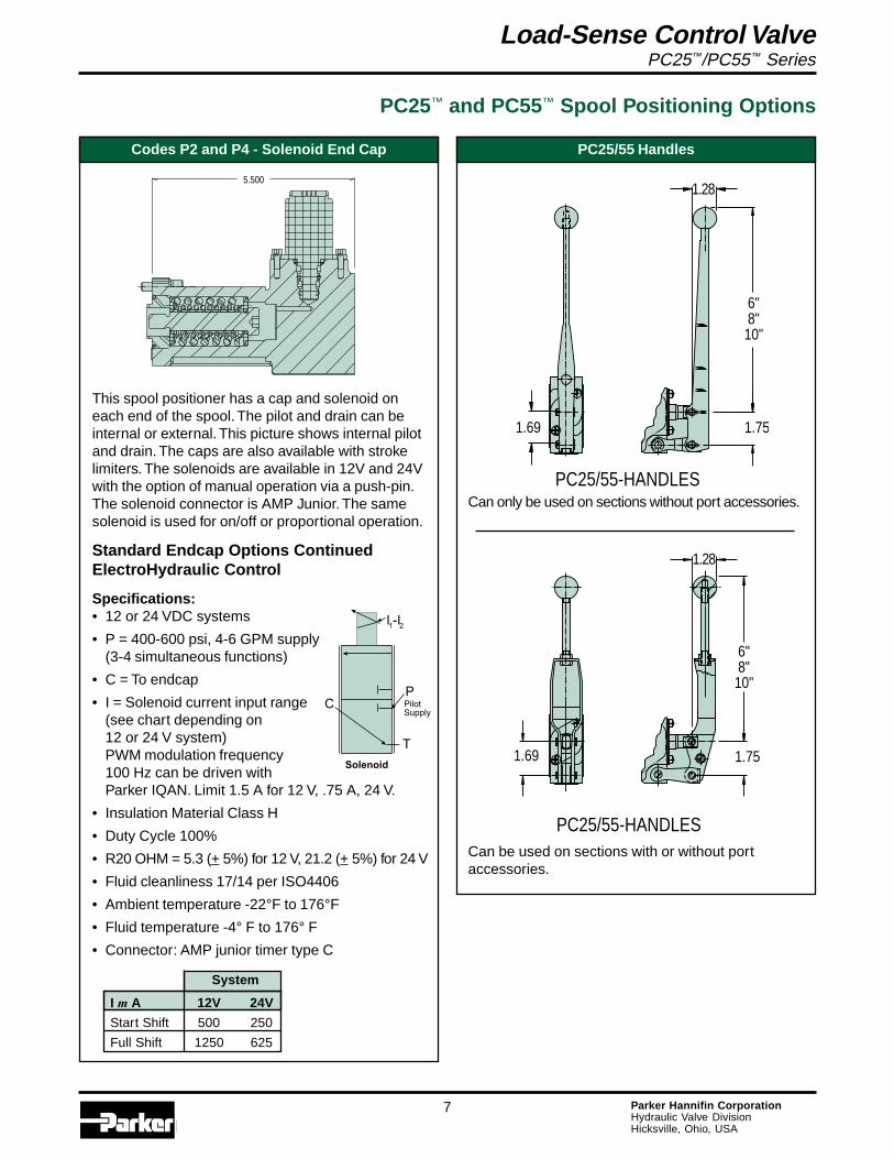
Can be used on sections with or without portaccessories.
PC25/55 Handles
PC25/55-HANDLES
1.28
6"8"10"
1.751.69
5.500
This spool positioner has a cap and solenoid oneach end of the spool. The pilot and drain can beinternal or external. This picture shows internal pilotand drain. The caps are also available with strokelimiters. The solenoids are available in 12V and 24Vwith the option of manual operation via a push-pin.The solenoid connector is AMP Junior. The samesolenoid is used for on/off or proportional operation.
Standard Endcap Options ContinuedElectroHydraulic Control
Specifications:• 12 or 24 VDC systems
• P = 400-600 psi, 4-6 GPM supply(3-4 simultaneous functions)
• C = To endcap
• I = Solenoid current input range(see chart depending on12 or 24 V system)PWM modulation frequency100 Hz can be driven withParker IQAN. Limit 1.5 A for 12 V, .75 A, 24 V.
• Insulation Material Class H
• Duty Cycle 100%
• R20 OHM = 5.3 (+ 5%) for 12 V, 21.2 (+ 5%) for 24 V
• Fluid cleanliness 17/14 per ISO4406
• Ambient temperature -22°F to 176°F
• Fluid temperature -4° F to 176° F
• Connector: AMP junior timer type C
Codes P2 and P4 - Solenoid End Cap
PC25™ and PC55™ Spool Positioning Options
Can only be used on sections without port accessories.
PC25/55-HANDLES
1.751.69
1.28
6"8"10"
System
I m A 12V 24V
Start Shift 500 250
Full Shift 1250 625

Load-Sense Control ValvePC25™/PC55™ Series
8 Parker Hannifin CorporationHydraulic Valve DivisionHicksville, Ohio, USA
Description of OperationWhen the spool is in neutral, the pump is connected tothe inlet core which is deadblocked at the outlet of thevalve. The load is being held by the spool and the pumpis in a standy condition.
When the spool is actuated, pump flow goes across thespool notches, opens the compensator and connectsthe pump to the load. The load pressure is shuttleddownstream to the outlet and sent to the pump via theload-sense port. Simultaneously, the load-sense signalis conditioned in the outlet and routed to the spring-endof the compensators. This enables a work-section tomaintain it’s selected flow regardless of changes inpressure.
As with all load-sense systems, venting of the load-sense signal is required when the valve spools arereturned to neutral. All of this is accomplished within thePC25 and PC55 valves.
To optimize the performance of these valves, the load-sense relief-valve is located in the outlet. It is screwadjustable. It’s setting determines the maximum pres-sure at which the valve will continue to provide flow tothe selected functions.
The relief valve in the inlet is referred to as a clipperrelief. It’s purpose is the clip the spikes normally associ-ated with the de-stroking of piston pumps. When theclipper relief valve opens, all of the pump flow is re-turned to tank. It should always be set at least 500 psihigher than the load-sense relief-valve to ensureoptimum performance.
PC25™ and PC55™
L.S.R/VB
A
B
THIS CHECK REQUIRES ABALL IF THE VALVECOMMUNICATES WITHANOTHER LOAD SENSE VALVE.
A
INDUCED LOADCHECK
CLIPPER R/V
Q-REG CHECKBALL
L.S. VENT FOR Q-MET.
ISOLATION SPOOLQ-MET CHECKS FLOW LIMIT ORIFICE
OUTLETFLOATD/A CYL.INLET
B
TK
INDUCED-LOADCHECK
Q-REG LOGICCHECK
A
P
COMPENSATOR
COMPENSATOR(Q-REG CHECK INSIDE)
INDUCED-LOADCHECK
Q-REG CORE
Q-METER NOTCHESQ-MET CORE
VENT FORQ-REG LOGICCHECK
INLET COREQ-MET CHECK
Load-Sense Control ValvePC25™/PC55™ Series
9 Parker Hannifin CorporationHydraulic Valve DivisionHicksville, Ohio, USA
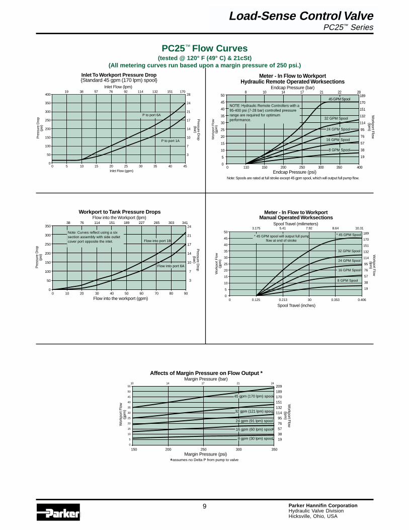
Meter - In Flow to WorkportManual Operated Worksections
Spool Travel (milimeters)3.175 5.41 7.92 8.64 10.31
* 45 GPM Spool
Spool Travel (inches)0 0.125 0.213 30 0.353 0.406
Wor
kpor
t Flo
w(g
pm)
189
170
151
132
114
95
76
57
38
19
Workport F
low(lpm
)
32 GPM Spool
24 GPM Spool
16 GPM Spool
8 GPM Spool
50
45
40
35
30
25
20
15
10
5
0
* 45 GPM spool will output full pumpflow at end of stroke
Workport to Tank Pressure DropsFlow into the Workport (lpm)
38 76 114 151 189 227 265 303 341
Flow into port 1B
Flow into the workport (gpm)0 10 20 30 40 50 60 70 80 90
Pressure D
rop(bar)
Pre
ssur
e D
rop
(psi
)
350
300
250
200
150
100
50
0
24
21
17
14
10
7
3
Flow into port 6A
Note: Curves reflect using a sixsection assembly with side outletcover port opposite the inlet.
Inlet To Workport Pressure Drop{Standard 45 gpm (170 lpm) spool}
Inlet Flow (lpm)19 38 57 76 92 114 132 151 170
P to port 6A
P to port 1A
Inlet Flow (gpm)0 5 10 15 20 25 30 35 40 45
Pressure D
rop(bar)
Pre
ssur
e D
rop
(psi
)
400
350
300
250
200
150
100
50
0
28
24
21
17
14
10
7
3
Meter - In Flow to WorkportHydraulic Remote Operated Worksections
Endcap Pressure (bar)8 10 14 17 21 22 28
45 GPM Spool
Endcap Pressure (psi)0 110 150 200 250 300 350 400
Wor
kpor
t Flo
w(g
pm)
189
170
151
132
114
95
76
57
38
19
Workport F
low(lpm
)
32 GPM Spool
24 GPM Spool
16 GPM Spool
8 GPM Spool
50
45
40
35
30
25
20
15
10
5
0
NOTE: Hydraulic Remote Controllers with a95-400 psi (7-28 bar) controlled pressurerange are required for optimumperformance.
Note: Spools are rated at full stroke except 45 gpm spool, which will output full pump flow.
Wor
kpor
t Flo
w(g
pm)
Affects of Margin Pressure on Flow Output * Margin Pressure (bar)
Margin Pressure (psi)
*assumes no Delta P from pump to valve
150 200 250 300 350
55
50
45
40
35
30
25
20
15
10
5
0
10 14 17 21 242091891701511321149576573819
Workport F
low(lpm
)
8 gpm (30 lpm) spool
45 gpm (170 lpm) spool
32 gpm (121 lpm) spool
24 gpm (91 lpm) spool
16 gpm (60 lpm) spool
PC25™ Flow Curves(tested @ 120° F (49° C) & 21cSt)
(All metering curves run based upon a margin pressure of 250 psi.)
Load-Sense Control ValvePC25™ Series
Load-Sense Control ValvePC25™/PC55™ Series
10 Parker Hannifin CorporationHydraulic Valve DivisionHicksville, Ohio, USA
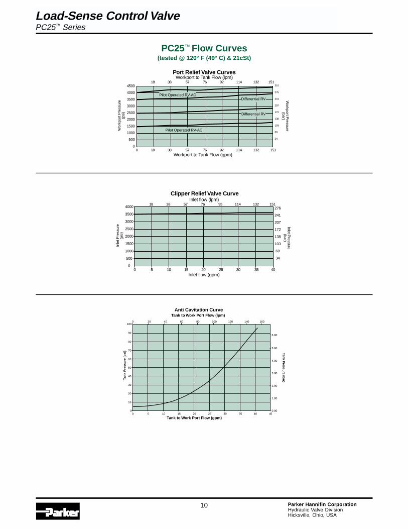
Clipper Relief Valve CurveInlet flow (lpm)
Inlet flow (gpm)0 5 10 15 20 25 30 35 40
Inlet Pressure
(bar)
4000
3500
3000
2500
2000
1500
1000
500
0
276
241
207
172
138
103
69
34
Inle
t Pre
ssur
e(p
si)
18 38 57 76 95 114 132 151
18 38 57 76 92 114 132 151
Differential RV
Wor
kpor
t Pre
ssur
e(p
si)
Workport to Tank Flow (gpm)
Port Relief Valve CurvesWorkport to Tank Flow (lpm)
310
276
241
207
172
138
103
69
34
0 18 38 57 76 92 114 132 151
Workport P
ressure(bar)
4500
4000
3500
3000
2500
2000
1500
1000
500
0
Differential RV
Pilot Operated RV-AC
Pilot Operated RV-AC
PC25™ Flow Curves(tested @ 120° F (49° C) & 21cSt)
Anti Cavitation Curve
0
10
20
30
40
50
60
70
80
0 5 10 15 20 25 30 35 45
Tank to Work Port Flow (gpm)
Tan
k P
ress
ure
(p
si)
0.00
1.00
2.00
3.00
4.00
5.00
0 20 40 60 80 100 120 140
Tank to Work Port Flow (lpm)
Tank P
ressure (b
ar)
90
100
40
6.00
160
Load-Sense Control ValvePC25™ Series
Load-Sense Control ValvePC25™/PC55™ Series
11 Parker Hannifin CorporationHydraulic Valve DivisionHicksville, Ohio, USA
OUTLET
HYD. REMOTED.A. 4 POS. FLOAT
D.A.
D.A.HYD. REMOTE
PNEUMATIC
PORT "A"
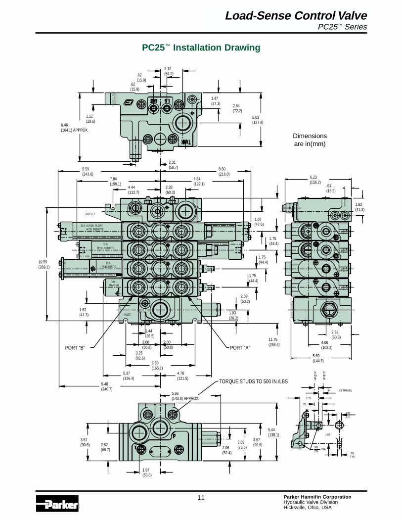
TORQUE STUDS TO 500 IN./LBS
INLET
PORT "B"
D.A.MANUAL
1.75(44.4)
1.88(47.6)
2.09(53.2)
2.06(52.4)
3.57(90.6)
1.44(36.5)
2.00(50.8)
2.00(50.8)
6.50(165.1)
3.25(82.6)
1.62(41.3)
1.97(50.0)
2.62(66.7)
3.57(90.6)
5.37(136.4)
9.48(240.7)
4.78(121.5)
1.03(26.2)
3.09(78.6)
5.44(138.1)
5.66(143.8) APPROX.
1.75(44.4)
1.75(44.4)
10.59(269.1)
11.75(298.4)
.62(15.9)
.62(15.9)
2.12(54.0)
1.12(28.6)
6.46(164.1) APPROX.
2.38(60.3)
7.84(199.1)
4.44(112.7)
9.59(243.6)
2.31(58.7)
2.84(72.2)
5.03(127.8)
1.47(37.3)
8.50(216.0)
7.84(199.1)
.72
.31
.38TYP.
1.75
1.69
.41 TRAVEL
.437
.427
.374
.381DIA.
HP@
"B"
HP@
"A"
6.23(158.2)
4.06(103.2)
2.38(60.3)
5.69(144.5)
.61(15.5)
1.62(41.3)
PC25™ Installation Drawing
Load-Sense Control ValvePC25™ Series
Dimensionsare in(mm)
Load-Sense Control ValvePC25™/PC55™ Series
12 Parker Hannifin CorporationHydraulic Valve DivisionHicksville, Ohio, USA
Box(1)
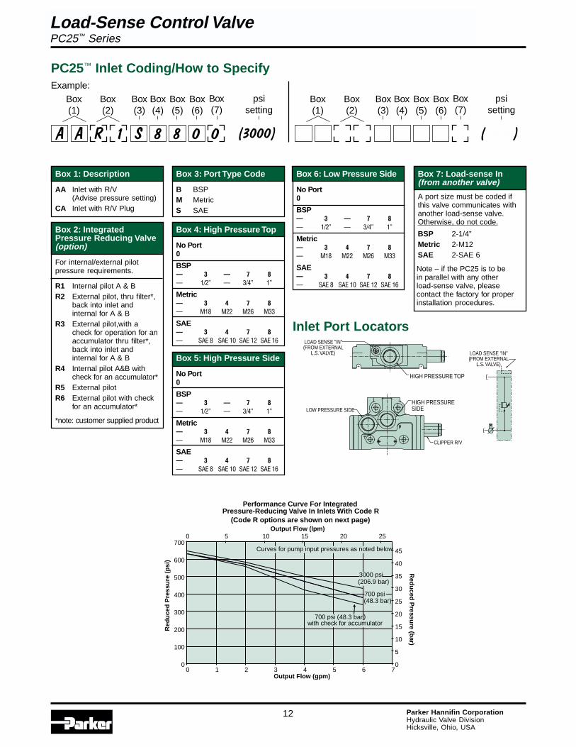
PC25™ Inlet Coding/How to Specify
Performance Curve For IntegratedPressure-Reducing Valve In Inlets With Code R
(Code R options are shown on next page)
0
100
200
300
400
500
600
700
0 1 2 3 4 5 6 7Output Flow (gpm)
Red
uce
d P
ress
ure
(p
si)
0
5
10
15
20
25
30
35
40
45
0 5 10 15 20 25Output Flow (lpm)
Red
uced
Pressu
re (bar)
700 psi (48.3 bar ) with check for accumulator
3000 psi(206.9 bar)
700 psi(48.3 bar)
Curves for pump input pressures as noted below
Inlet Port Locators
HIGH PRESSURE TOP
LOAD SENSE "IN"(FROM EXTERNAL
L.S. VALVE)
LOAD SENSE "IN"(FROM EXTERNAL
L.S. VALVE)
HIGH PRESSURESIDE
CLIPPER R/V
LOW PRESSURE SIDE
Box 1: Description
AA Inlet with R/V(Advise pressure setting)
CA Inlet with R/V Plug
Box 3: Port Type Code
B BSPM MetricS SAE
Box 5: High Pressure Side
No PortO
BSP— 3 — 7 8— 1/2” — 3/4” 1”
Metric— 3 4 7 8— M18 M22 M26 M33
SAE— 3 4 7 8— SAE 8 SAE 10 SAE 12 SAE 16
Box 6: Low Pressure Side
No PortO
BSP— 3 — 7 8— 1/2” — 3/4” 1”
Metric— 3 4 7 8— M18 M22 M26 M33
SAE— 3 4 7 8— SAE 8 SAE 10 SAE 12 SAE 16
A A R 1 S 8 8 0 0
Box 2: IntegratedPressure Reducing Valve(option)
For internal/external pilotpressure requirements.
R1 Internal pilot A & BR2 External pilot, thru filter*,
back into inlet andinternal for A & B
R3 External pilot,with acheck for operation for anaccumulator thru filter*,back into inlet andinternal for A & B
R4 Internal pilot A&B withcheck for an accumulator*
R5 External pilotR6 External pilot with check
for an accumulator*
*note: customer supplied product
Box(2)
Box(4)
Box(5)
Box(7)
Box(6)
Box 7: Load-sense In(from another valve)
A port size must be coded ifthis valve communicates withanother load-sense valve.Otherwise, do not code.
BSP 2-1/4”Metric 2-M12SAE 2-SAE 6
Example:
Box 4: High Pressure Top
No PortO
BSP— 3 — 7 8— 1/2” — 3/4” 1”
Metric— 3 4 7 8— M18 M22 M26 M33
SAE— 3 4 7 8— SAE 8 SAE 10 SAE 12 SAE 16
Note – if the PC25 is to bein parallel with any otherload-sense valve, pleasecontact the factory for properinstallation procedures.
(3000)
Box(3)
Box(1)
Box(2)
Box(4)
Box(5)
Box(7)
Box(6)
Box(3)
psisetting
(3000)
psisetting
Load-Sense Control ValvePC25™ Series

Load-Sense Control ValvePC25™/PC55™ Series
13 Parker Hannifin CorporationHydraulic Valve DivisionHicksville, Ohio, USA
PC25™ Inlet Coding/How to SpecifyInlets with the integrated pressure-reducing valve are denoted by the letter R in the 3rd space of thecoding description - followed by a number (1-6) in the 4th space.
Internal pilot to A and B sides of the valve. Internal pilot to A and B sides of the valve with a check foroperation with an accumulator (supplied by customer).
Code R1 Code R4
High Pressure Port
High Pressure Port
PressureReducingValve
Pilot In From Filter
Load Sense "IN"(From External L.S. VALVE)
Pilot Out To Filter
High Pressure Port
High Pressure Port
PressureReducingValve
PressureReducingValve
External pilot for the option of plumbing thru a filter (supplied bycustomer) and then back into the inlet. Pilot pressure is theninternal to the A and B sides of the valve.
External pilot only.
Code R2 Code R5
Pilot In FromFilter/Accumulator
Pilot Out ToFilter/Accumulator
High Pressure Port
High Pressure Port
PressureReducingValve
PressureReducingValve
Load Sense "IN"(From External L.S. Valve)
Pilot Out ToAccumulator
High Pressure Port
High Pressure Port
PressureReducingValve
PressureReducingValve
Same as Code R2, except has a check for operation with anaccumulator (supplied by customer). When pressure falls belowa defined level, the check closes and the accumulator suppliespilot pressure to the valve.
External pilot only with a check for operation with an accumula-tor (supplied by customer).
Code R3 Code R6
Load Sense "IN"(From External L.S. Valve)
Pilot Out
High Pressure Port
High Pressure Port
PressureReducingValve
PressureReducingValve
Load Sense "IN"(From External L.S. Valve)
Pilot Out
High Pressure Port
High Pressure Port
Pilot In FromFilter/Accumulator
PressureReducingValve
PressureReducingValve
Load-Sense Control ValvePC25™ Series

Load-Sense Control ValvePC25™/PC55™ Series
14 Parker Hannifin CorporationHydraulic Valve DivisionHicksville, Ohio, USA
HDouble Acting Cylinder
NSingle Acting Motor
(port B)
LDouble Acting Motor
GDouble Acting Cylinder4th Position Float (IN)
JSingle Acting Cylinder
(port B)
RDouble Acting Cylinder
4th Pos. Regen. (IN)
PC25™ Work Section Coding/How to Specify
Box 1: Description
H Double Acting CylinderL Double Acting MotorJ Single Acting Cylinder
(port B)N Single Acting Motor
(port B)G Double Acting Cyl.
4th Pos. Float (IN)R Double Acting Cyl.
4th Pos. Regen. (IN)(available in code X -hydraulic remoteoperator only)
Note - Codes G and R areavailable as left-handedsections only.
Box 2: Spool Flow
GPM (The last two digits denotesflow @ full stroke, except 45 gpmspool will output full pump flow.Margin pressure 250 psi/17 bar.)
Double Acting Cylinder145, 132, 124, 116, 108
Double Acting Motor245, 232, 224, 216, 208
Single Acting Cylinder (port B)345, 332, 324, 316, 308
Single Acting Motor (port B)445, 432, 424, 416, 408
Dbl. Act. Cyl.4th Pos. Float (IN)545, 532
Box 3: Operator (SpoolPositioning)
(Left or right handed section)
Left Right
Spring Return A E
(3) Position Detent B F
Spring Return with4th Pos. Detent (IN) C -
(Left-handedassembly only)Spring ReturnOut/Detent In D H
D. E. SolenoidOn/Off orProportional 12V P2 -
D. E. SolenoidOn/Off orProportional 24V P4 -
Single EndedPneumatic V U
Hydraulic Remote,Proportional X -
Hydraulic Remote,On/Off XP -Note: Codes P must have pilotand drain codes from Box 3A.
(Left) (Right)
Box 3A: Optional Pilotand Drain for P2 & P4
Available Codes
A External Pilot and Drain
B External Pilot andInternal Drain
C Internal Pilot and Drain
D Internal Pilot andExternal Drain
Porting (Box 4)
No PortO
BSP— B3 — B7— 1/2” — 3/4”
Metric— M3 M4 M7— M18 M22 M26
SAE— S3 S4 S7— SAE 8 SAE 10 SAE 12
Box 5A & 5B:Port A & B Accessory
(Apply a code for each port)
0 Not Machined
1 R/V-A/C ScrewAdjustable
2 Anti-cavitation Check
3 R/V Shim Adjustable
5 Plastic Closure
6 R/V Screw Adjustable
9 Steel Plug
Box 6: Q Reg. Check Ball
(Section next to inlet does nottake a ball unless it communi-cates with another load-sensevalve)
A No Ball
B Ball
Function Schematics
Box(5A)
Box(2)
Box(3)
Box(3A)
Box(6)
Box(4)
Box(5B)
Box(1)
Box(3B)
Box(5A)
Box(2)
Box(3)
Box(3A)
Box(6)
Box(4)
Box(5B)
Box(1)
Box(3B)
H 1 4 5 A S 7 1 1 A
Example:
(2000 / 1500)
psi settingfor ports A & B
(2000 / 1500)
psi settingfor ports A & B
Box 3B: Optional StrokeLimiter for P2 & P4
For A & B 1
For A Only 2
For B Only 3
Load-Sense Control ValvePC25™ Series
B
A
TK
P
B
A
TK
P
B
A
TK
P
B
A
TK
P
B
A
TK
P
B
TK
P
A
Load-Sense Control ValvePC25™/PC55™ Series
15 Parker Hannifin CorporationHydraulic Valve DivisionHicksville, Ohio, USA
Box(1)
Box(2)
Box(3)
Box(4)
Box(5)
Box(6)
OptionalBox(7)
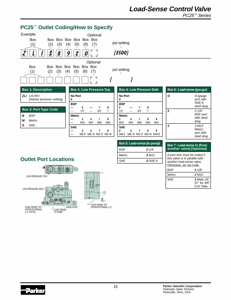
Outlet Port Locations
�����������������������������������������������
��!������"������
��������������"��
���������������������������������
��!������"������
PC25™ Outlet Coding/How to Specify
Box 1: Description
ZLI L/S R/V(Advise pressure setting)
Box 5: Load-sense (to pump)
BSP 2-1/4”
Metric 2-M12
SAE 2-SAE 6
Box 2: Port Type Code
B BSP
M Metric
S SAE
Box 3: Low Pressure Top
No PortO
BSP— 3 — 7 8— 1/2” — 3/4” 1”
Metric— 3 4 7 8— M18 M22 M26 M33
SAE— 3 4 7 8— SAE 8 SAE 10 SAE 12 SAE 16
Box 4: Low Pressure Side
No PortO
BSP3 — 7 81/2” — 3/4” 1”
Metric3 4 7 8 9M18 M22 M26 M33 M42
SAE3 4 7 8 9SAE 8 SAE 10 SAE 12 SAE 16 SAE20
Box 6: Load-sense (gauge)
O O-gaugeport withSAE-6steel plug
2 2-1/4”BSP portwith steelplug
2 2-M12Metricport withsteel plug
Box 7: Load-sense In (fromanother valve) (Optional)
A port size must be coded ifthis valve is in parallel withanother load-sense valve.Otherwise, do not code.
BSP 1-1/8”
Metric 1-M10
SAE 1-Male JIC37° for 3/8”O.D. Tube
Z L I S 8 9 2 0
Box(1)
Box(2)
Box(3)
Box(4)
Box(5)
Box(6)
Example:
OptionalBox(7)
(3500)
psi setting
(????????)
psi setting
Load-Sense Control ValvePC25™ Series
Load-Sense Control ValvePC25™/PC55™ Series
16 Parker Hannifin CorporationHydraulic Valve DivisionHicksville, Ohio, USA
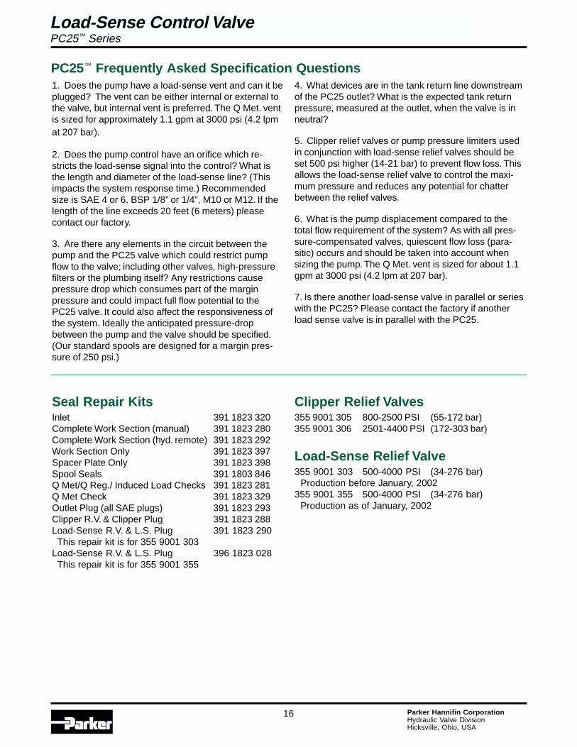
1. Does the pump have a load-sense vent and can it beplugged? The vent can be either internal or external tothe valve, but internal vent is preferred. The Q Met. ventis sized for approximately 1.1 gpm at 3000 psi (4.2 lpmat 207 bar).
2. Does the pump control have an orifice which re-stricts the load-sense signal into the control? What isthe length and diameter of the load-sense line? (Thisimpacts the system response time.) Recommendedsize is SAE 4 or 6, BSP 1/8” or 1/4”, M10 or M12. If thelength of the line exceeds 20 feet (6 meters) pleasecontact our factory.
3. Are there any elements in the circuit between thepump and the PC25 valve which could restrict pumpflow to the valve; including other valves, high-pressurefilters or the plumbing itself? Any restrictions causepressure drop which consumes part of the marginpressure and could impact full flow potential to thePC25 valve. It could also affect the responsiveness ofthe system. Ideally the anticipated pressure-dropbetween the pump and the valve should be specified.(Our standard spools are designed for a margin pres-sure of 250 psi.)
Seal Repair KitsInlet 391 1823 320Complete Work Section (manual) 391 1823 280Complete Work Section (hyd. remote) 391 1823 292Work Section Only 391 1823 397Spacer Plate Only 391 1823 398Spool Seals 391 1803 846Q Met/Q Reg./ Induced Load Checks 391 1823 281Q Met Check 391 1823 329Outlet Plug (all SAE plugs) 391 1823 293Clipper R.V. & Clipper Plug 391 1823 288Load-Sense R.V. & L.S. Plug 391 1823 290 This repair kit is for 355 9001 303Load-Sense R.V. & L.S. Plug 396 1823 028 This repair kit is for 355 9001 355
Clipper Relief Valves355 9001 305 800-2500 PSI (55-172 bar)355 9001 306 2501-4400 PSI (172-303 bar)
Load-Sense Relief Valve355 9001 303 500-4000 PSI (34-276 bar) Production before January, 2002355 9001 355 500-4000 PSI (34-276 bar) Production as of January, 2002
PC25™ Frequently Asked Specification Questions4. What devices are in the tank return line downstreamof the PC25 outlet? What is the expected tank returnpressure, measured at the outlet, when the valve is inneutral?
5. Clipper relief valves or pump pressure limiters usedin conjunction with load-sense relief valves should beset 500 psi higher (14-21 bar) to prevent flow loss. Thisallows the load-sense relief valve to control the maxi-mum pressure and reduces any potential for chatterbetween the relief valves.
6. What is the pump displacement compared to thetotal flow requirement of the system? As with all pres-sure-compensated valves, quiescent flow loss (para-sitic) occurs and should be taken into account whensizing the pump. The Q Met. vent is sized for about 1.1gpm at 3000 psi (4.2 lpm at 207 bar).
7. Is there another load-sense valve in parallel or serieswith the PC25? Please contact the factory if anotherload sense valve is in parallel with the PC25.
Load-Sense Control ValvePC25™ Series

Load-Sense Control ValvePC25™/PC55™ Series
17 Parker Hannifin CorporationHydraulic Valve DivisionHicksville, Ohio, USA
Customer: City: State: Zip:
Application: Annual Usage:
Pump Type: Pump Control: Stand-by psi/bar: Margin psi/bar:
Filtration: ISO Bypass Non Bypass
Pilot Filtration: ISO Bypass Non Bypass
Primary gpm/lpm Input: @ psi/bar Operating Temp: F/C
Max. Temp: F/C Viscosity: SSU @ 100F/cFp@38C Oil Type:
��#��$����
��#��$����
��#��$����
��#��$����
��#��$����
��#��$����
��#��$����
��#��$����
��#� ����
�%�&��'���'��(���)���&*
�����)'��'���'��(���)���&*
��+)���'�, ��+)���'�,�-�!����� �.� ��� �/�����������
��)0�1 -�*2 �'),,�')3 ��4 �'),,�') ��'�,
�)0���&���&0���&
��+)
&�)����'�
����
����)���&*
��'���
��'��5
��'���
��'��5
��'���
��'��5
��'���
��'��5
SPOOL TYPE... DAC DAM SAC DAC DAM SAC DAC DAM SAC DAC DAM SACDAF DAR SAM DAF DAR SAM DAF DAR SAM DAF DAR SAM
SPOOL OPER... SR DT SRDT DES SR DT SRDT DES SR DT SRDT DES SR DT SRDT DESHRM HRNM A HRM HRNM A HRM HRNM A HRM HRNM A
FLOW... 45 32 24 16 8 45 32 24 16 8 45 32 24 16 8 45 32 24 16 8
PORT A... RV3 RV6 RVAC AC RV3 RV6 RVAC AC RV3 RV6 RVAC AC RV3 RV6 RVAC AC
PORT B... RV3 RV6 RVAC AC RV3 RV6 RVAC AC RV3 RV6 RVAC AC RV3 RV6 RVAC AC
HANDLES... 6” 8” 10” 6” 8” 10” 6” 8” 10” 6” 8” 10”
Date:
Left-handAssembly
Right-handAssembly
PC25™ Valve Specification Sheet
(Left)
(Right)
Spool TypeDAC Double Acting
Cylinder
DAM Double ActingMotor
SAC Single ActingCylinder
DAF Double Acting4 POS Float
DAR Double Acting4 POS Regen
SAM Single ActingMotor
Spool OperationSR Spring Return
DT 3 Position Detent
SRDT Spring Return In,Detent Out
DES Double EndedSolenoid 12/24 VDC
HRM Hydraulic RemoteMetered
HRNM Hydraulic RemoteNo Metering
A Air
Port AccessoriesRV3 Relief Valve Shim
Adjust
RV6 Relief Valve ScrewAdjust
RVAC Relief Valve/Anti-Cav.Screw Adjust
AC Anti-Cavitation
Flow @ Full Stroke(based on 250 psi margin pressure)
gpm 45 -32 - 24 - 16 - 8
lpm 170 - 121 - 91 - 61 - 30Note: The 45 gpm spool will output fullpump displacement at full stroke.
Load-Sense Control ValvePC25™ Series
Load-Sense Control ValvePC25™/PC55™ Series
18 Parker Hannifin CorporationHydraulic Valve DivisionHicksville, Ohio, USA
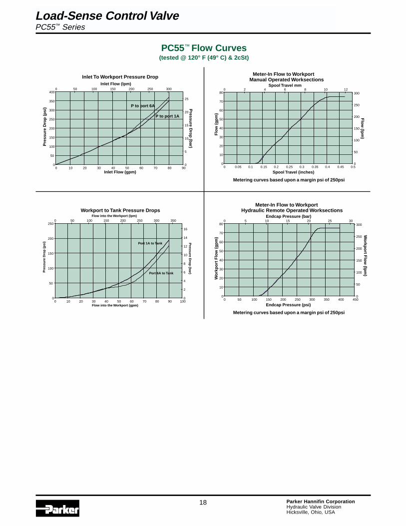
PC55™ Flow Curves(tested @ 120° F (49° C) & 2cSt)
Meter-In Flow to WorkportManual Operated Worksections
0
10
20
30
40
50
60
70
80
0 0.05 0.1 0.15 0.2 0.25 0.3 0.35 0.4 0.45 0.5
Spool Travel (inches)
Flo
w (
gp
m)
0
50
100
150
200
250
3000 2 4 6 8 10 12
Spool Travel mm
Flo
w (lp
m)
Meter-In Flow to WorkportHydraulic Remote Operated Worksections
0
10
20
30
40
50
60
70
80
0 50 100 150 200 250 300 350 400 450
Endcap Pressure (psi)
Wo
rkp
ort
Flo
w (
gp
m)
0
50
100
150
200
250
3000 5 10 15 20 25 30
Endcap Pressure (bar)
Wo
rkpo
rt Flo
w (lp
m)
Load-Sense Control ValvePC55™ Series
Inlet To Workport Pressure Drop
0
50
100
150
200
250
300
350
400
0 10 20 30 40 50 60 70 80 90Inlet Flow (gpm)
Pre
ssu
re D
rop
(p
si)
0
5
10
15
20
25
0 50 100 150 200 250 300
Inlet Flow (lpm)
Pressu
re Dro
p (b
ar)
P to port 1A
P to port 6A
Workport to Tank Pressure Drops
0
50
100
150
200
250
0 10 20 30 40 50 60 70 80 90 100Flow into the Workport (gpm)
Pre
ssu
re D
rop
(p
si)
0
2
4
6
8
10
12
14
16
0 50 100 150 200 250 300 350Flow into the Workport (lpm)
Pressu
re Dro
p (b
ar)
Port 1A to Tank
Port 6A to Tank
Metering curves based upon a margin psi of 250psi
Metering curves based upon a margin psi of 250psi
Load-Sense Control ValvePC25™/PC55™ Series
19 Parker Hannifin CorporationHydraulic Valve DivisionHicksville, Ohio, USA
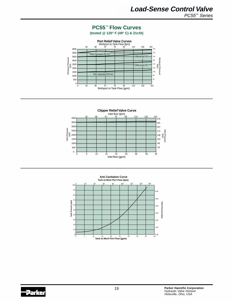
Clipper Relief Valve CurveInlet flow (lpm)
Inlet flow (gpm)0 5 10 15 20 25 30 35 40
Inlet Pressure
(bar)
4000
3500
3000
2500
2000
1500
1000
500
0
276
241
207
172
138
103
69
34
Inle
t Pre
ssur
e(p
si)
18 38 57 76 95 114 132 151
18 38 57 76 92 114 132 151
Differential RV
Wor
kpor
t Pre
ssur
e(p
si)
Workport to Tank Flow (gpm)
Port Relief Valve CurvesWorkport to Tank Flow (lpm)
310
276
241
207
172
138
103
69
34
0 18 38 57 76 92 114 132 151
Workport P
ressure(bar)
4500
4000
3500
3000
2500
2000
1500
1000
500
0
Differential RV
Pilot Operated RV-AC
Pilot Operated RV-AC
PC55™ Flow Curves(tested @ 120° F (49° C) & 21cSt)
Load-Sense Control ValvePC55™ Series
Anti Cavitation Curve
0
10
20
30
40
50
60
70
80
0 5 10 15 20 25 30 35 45
Tank to Work Port Flow (gpm)
Tan
k P
ress
ure
(p
si)
0.00
1.00
2.00
3.00
4.00
5.00
0 20 40 60 80 100 120 140
Tank to Work Port Flow (lpm)
Tank P
ressure (b
ar)
90
100
40
6.00
160

Load-Sense Control ValvePC25™/PC55™ Series
20 Parker Hannifin CorporationHydraulic Valve DivisionHicksville, Ohio, USA
.53(13.5).53
(13.5)
3.25(82.6)
1.12(28.6)
3.24(82.3)
3.25(82.6)
4.77(121.1)
10.07(255.7)
7.04(178.9)
3.09(78.6)
1.83(46.4)
5.62(142.8)
6.22(158.0)
9.39(238.6)
OUTLET
D.A. 4 POS. FLOATHYD. REMOTE
PORT "A"
TORQUE STUDS TO 900 IN-LBS
D.A.MANUAL
D.A.PNEUMATIC
PORT "B"
INLET
D.A.HYD. REMOTE
2.72(69.1)
2.19(55.6)
8.43(214.0)
4.78(121.4)
6.47(164.3)
6.97(177.0)
2.22(56.3)
2.00(50.8)
1.31(33.3)
2.50(63.6)
4.03(102.3)
3.53(89.7)
1.72(43.7)
2.25(57.1)
2.25(57.1)
6.09(154.7)
1.91(48.4)
7.88(200.0)
3.06(77.7)
4.03(102.4)
10.06(255.4)
1.00(25.4)
6.19(157.2)
5.25(133.3)
6.01(152.6) APPROX.
1.53(38.9)
2.00(50.8)
13.50(342.9)
2.00(50.8)11.58
(294.1)
14.00(355.6)
HP@"B"HP@"A"
.562
.552
.47.47
2.02
.38.94
1.73
.44
.507
.500 DIA.381.374 DIA
PC55™ Installation Drawing
Load-Sense Control ValvePC55™ Series
Dimensionsare in(mm)

Load-Sense Control ValvePC25™/PC55™ Series
21 Parker Hannifin CorporationHydraulic Valve DivisionHicksville, Ohio, USA
PC55™ Inlet Coding/How to Specify
Box(1)
Inlet Port Locations
HIGH PRESSURE TOP
LOAD SENSE "IN"(FROM EXTERNAL
L.S. VALVE)
LOAD SENSE "IN"(FROM EXTERNAL
L.S. VALVE)
HIGH PRESSURESIDE
CLIPPER R/V
LOW PRESSURE SIDE
Box 2: Port Type Code
B BSPM MetricS SAE
Box 3: High Pressure Top
No PortO
BSP— 7 8 9— 3/4” 1” 1¼”
Metric— 7 8 9— M26 M33 M42
SAE— 7 8 9— SAE 12 SAE 16 SAE 20
Box 4: High Pressure Top
No PortO
BSP— 7 8 9— 3/4” 1” 1¼”
Metric— 7 8 9— M26 M33 M42
SAE— 7 8 9— SAE 12 SAE 16 SAE 20
Box 5: Low Pressure Side
No PortO
BSP— 7 8 9 10— 3/4” 1” 1¼” 1½
Metric— 7 8 9 10— M26 M33 M42 M48
SAE— 7 8 9 10— SAE 12 SAE 16 SAE 20 SAE 24
A A S 8 8 0 0
Box(2)
Box(3)
Box(4)
Box(6)
Box(5)
Box 6: Load-sense In(from another valve)
A port size must be coded ifthis valve communicates withanother load-sense valve.Otherwise, do not code.
BSP 2-1/4”Metric 2-M12SAE 2-SAE 6
Example:
Box 1: Description
AA Inlet with R/V(Advise pressure setting)
CA Inlet with R/V Plug
Box(1)
Box(2)
Box(3)
Box(4)
Box(6)
Box(5)
(3500)
psi setting
(3500)
psi setting
Load-Sense Control ValvePC55™ Series
Note – if the PC55 is to bein parallel with any otherload-sense valve, pleasecontact the factory for properinstallation procedures.

Load-Sense Control ValvePC25™/PC55™ Series
22 Parker Hannifin CorporationHydraulic Valve DivisionHicksville, Ohio, USA
PC55™ Work Section Coding/How to Specify
Box 1: Description
H Double Acting CylinderL Double Acting MotorJ Single Acting Cylinder
(port B)N Single Acting Motor
(port B)G Double Acting Cyl.
4th Pos. Float (IN)R Double Acting Cyl.
4th Pos. Regen. (IN)(available in code X -hydraulic remoteoperator only)
Note - Codes G and R areavailable as left-handedsections only.
Box 2: Spool Flow
GPM (The last two digitsdenotes flow @ full stroke.Margin pressure 250 psi/17 bar.)
Double Acting Cylinder*
Double Acting Motor*
Single Acting Cylinder (port B)*
Single Acting Motor (port B)*
Dbl. Act. Cyl. 4th Pos. Float (IN)*
*Contact division for spoolavailable.
Box 3: Operator(Spool Positioning)
(Left or right handed section)
Left Right
Spring Return A E
(3) Position Detent B F
D. E. SolenoidOn/Off orProportional 12V P2 -
D. E. SolenoidOn/Off orProportional 24V P4 -
Single EndedPneumatic V U
Hydraulic Remote,Proportional X -
Hydraulic Remote,On/Off XP -
Note: Codes P must have pilotand drain codes from Box 3A.
(Left) (Right)
Box 3A: Optional Pilotand Drain for P2 & P4
A External Pilot and Drain
B External Pilot andInternal Drain
C Internal Pilot and Drain
D Internal Pilot andExternal Drain
Porting (Box 4)
No PortO
BSP— B7 B8— 3/4” 1”
Metric— M7 M8— M26 M33
SAE— S7 S8— SAE 12 SAE 16
Box 5A & 5B:Port A & B Accessory
(apply a code for each port)
0 Not Machined
1 R/V-A/C ScrewAdjustable
2 Anti-cavitation Check
3 R/V Shim Adjustable
5 Plastic Closure
6 R/V Screw Adjustable
9 Steel Plug
Box 6: Q Reg. Check Ball
(section next to inlet does nottake a ball unless it communi-cates with another load-sensevalve)
A No Ball
B Ball
Box(5A)
Box(2)
Box(3)
Box(3A)
Box(6)
Box(4)
Box(5B)
Box(1)
Box(3B)
Box(5A)
Box(2)
Box(3)
Box(3A)
Box(6)
Box(4)
Box(5B)
Box(1)
Box(3B)
H 1 7 0 A S 7 1 1 A
Example:
(2000 / 1500)
psi settingfor ports A & B
(2000 / 1500)
psi settingfor ports A & B
Box 3B: Optional StrokeLimiter for P2 & P4
For A & B 1
For A Only 2
For B Only 3
HDouble Acting Cylinder
NSingle Acting Motor
(port B)
LDouble Acting Motor
GDouble Acting Cylinder4th Position Float (IN)
JSingle Acting Cylinder
(port B)
RDouble Acting Cylinder
4th Pos. Regen. (IN)
Function SchematicsB
A
TK
P
B
A
TK
P
B
A
TK
P
B
A
TK
P
B
A
TK
P
B
TK
P
A
Load-Sense Control ValvePC55™ Series
Load-Sense Control ValvePC25™/PC55™ Series
23 Parker Hannifin CorporationHydraulic Valve DivisionHicksville, Ohio, USA
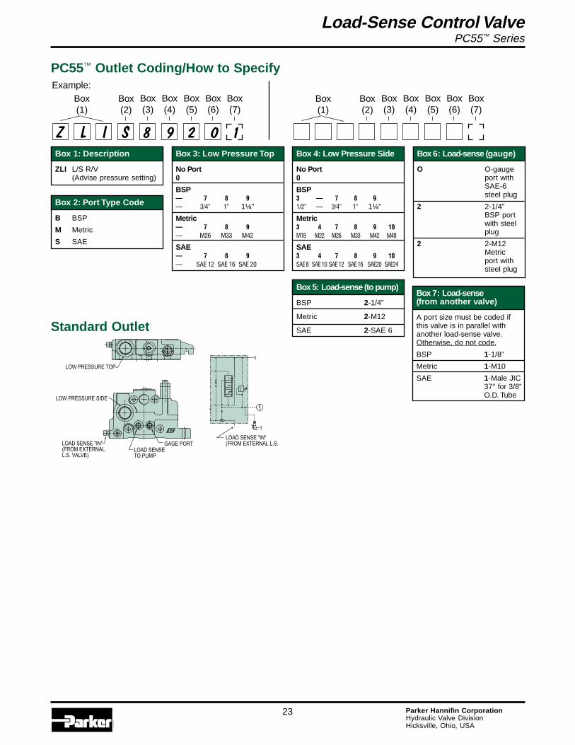
PC55™ Outlet Coding/How to Specify
Box(1)
Box(2)
Box(3)
Box(4)
Box(5)
Box(6)
Box(7)
Standard Outlet
�����������������������������������������������
��!������"������
��������������"��
���������������������������������
��!������"������
Box 1: Description
ZLI L/S R/V(Advise pressure setting)
Box 5: Load-sense (to pump)
BSP 2-1/4”
Metric 2-M12
SAE 2-SAE 6
Box 2: Port Type Code
B BSP
M Metric
S SAE
Box 3: Low Pressure Top
No PortO
BSP— 7 8 9— 3/4” 1” 1¼”
Metric— 7 8 9— M26 M33 M42
SAE— 7 8 9— SAE 12 SAE 16 SAE 20
Box 4: Low Pressure Side
No PortO
BSP3 — 7 8 91/2” — 3/4” 1” 1¼”
Metric3 4 7 8 9 10M18 M22 M26 M33 M42 M48
SAE3 4 7 8 9 10SAE 8 SAE 10 SAE 12 SAE 16 SAE20 SAE24
Box 6: Load-sense (gauge)
O O-gaugeport withSAE-6steel plug
2 2-1/4”BSP portwith steelplug
2 2-M12Metricport withsteel plug
Box 7: Load-sense(from another valve)
A port size must be coded ifthis valve is in parallel withanother load-sense valve.Otherwise, do not code.
BSP 1-1/8”
Metric 1-M10
SAE 1-Male JIC37° for 3/8”O.D. Tube
Z L I S 8 9 2 0 1
Box(1)
Box(2)
Box(3)
Box(4)
Box(5)
Box(6)
Box(7)
Example:
Load-Sense Control ValvePC55™ Series
Load-Sense Control ValvePC25™/PC55™ Series
24 Parker Hannifin CorporationHydraulic Valve DivisionHicksville, Ohio, USA
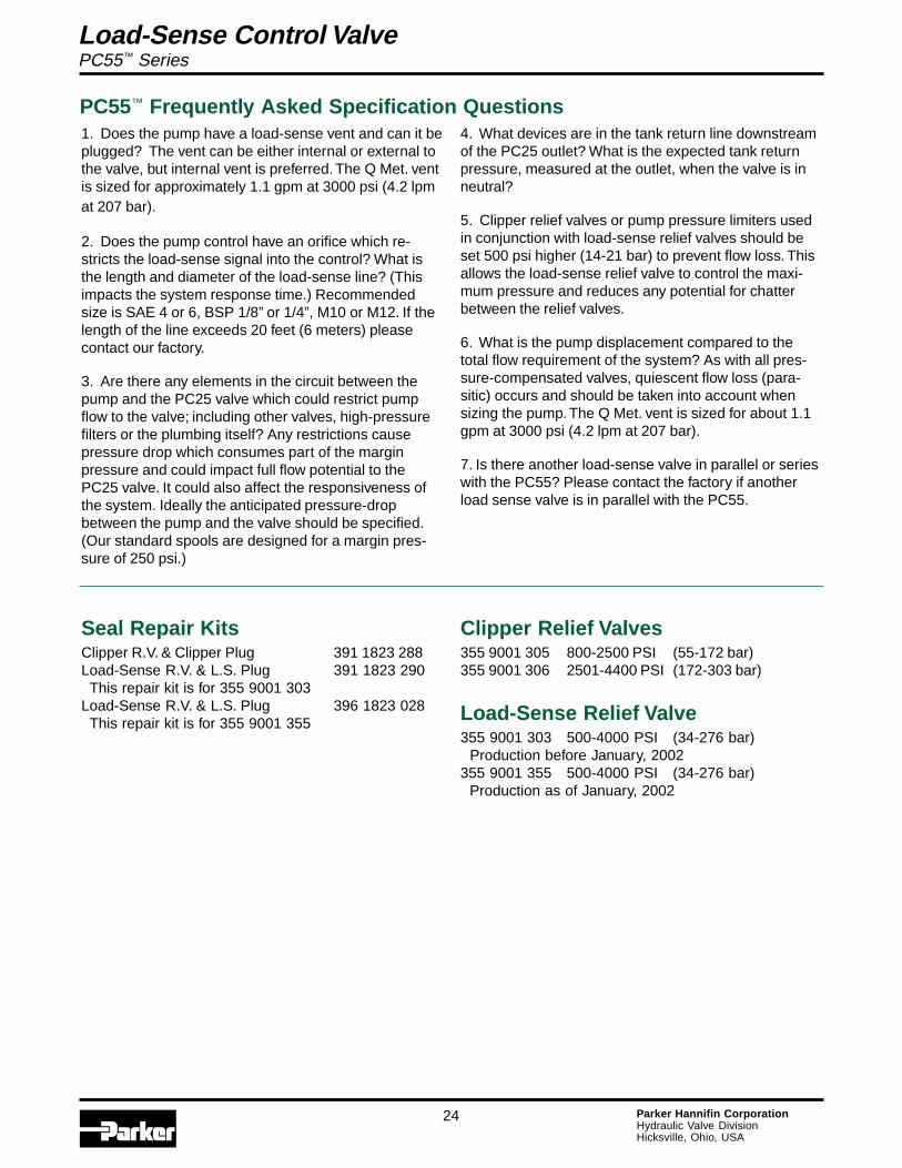
1. Does the pump have a load-sense vent and can it beplugged? The vent can be either internal or external tothe valve, but internal vent is preferred. The Q Met. ventis sized for approximately 1.1 gpm at 3000 psi (4.2 lpmat 207 bar).
2. Does the pump control have an orifice which re-stricts the load-sense signal into the control? What isthe length and diameter of the load-sense line? (Thisimpacts the system response time.) Recommendedsize is SAE 4 or 6, BSP 1/8” or 1/4”, M10 or M12. If thelength of the line exceeds 20 feet (6 meters) pleasecontact our factory.
3. Are there any elements in the circuit between thepump and the PC25 valve which could restrict pumpflow to the valve; including other valves, high-pressurefilters or the plumbing itself? Any restrictions causepressure drop which consumes part of the marginpressure and could impact full flow potential to thePC25 valve. It could also affect the responsiveness ofthe system. Ideally the anticipated pressure-dropbetween the pump and the valve should be specified.(Our standard spools are designed for a margin pres-sure of 250 psi.)
Seal Repair KitsClipper R.V. & Clipper Plug 391 1823 288Load-Sense R.V. & L.S. Plug 391 1823 290 This repair kit is for 355 9001 303Load-Sense R.V. & L.S. Plug 396 1823 028 This repair kit is for 355 9001 355
Clipper Relief Valves355 9001 305 800-2500 PSI (55-172 bar)355 9001 306 2501-4400 PSI (172-303 bar)
Load-Sense Relief Valve355 9001 303 500-4000 PSI (34-276 bar) Production before January, 2002355 9001 355 500-4000 PSI (34-276 bar) Production as of January, 2002
PC55™ Frequently Asked Specification Questions4. What devices are in the tank return line downstreamof the PC25 outlet? What is the expected tank returnpressure, measured at the outlet, when the valve is inneutral?
5. Clipper relief valves or pump pressure limiters usedin conjunction with load-sense relief valves should beset 500 psi higher (14-21 bar) to prevent flow loss. Thisallows the load-sense relief valve to control the maxi-mum pressure and reduces any potential for chatterbetween the relief valves.
6. What is the pump displacement compared to thetotal flow requirement of the system? As with all pres-sure-compensated valves, quiescent flow loss (para-sitic) occurs and should be taken into account whensizing the pump. The Q Met. vent is sized for about 1.1gpm at 3000 psi (4.2 lpm at 207 bar).
7. Is there another load-sense valve in parallel or serieswith the PC55? Please contact the factory if anotherload sense valve is in parallel with the PC55.
Load-Sense Control ValvePC55™ Series
Load-Sense Control ValvePC25™/PC55™ Series
25 Parker Hannifin CorporationHydraulic Valve DivisionHicksville, Ohio, USA
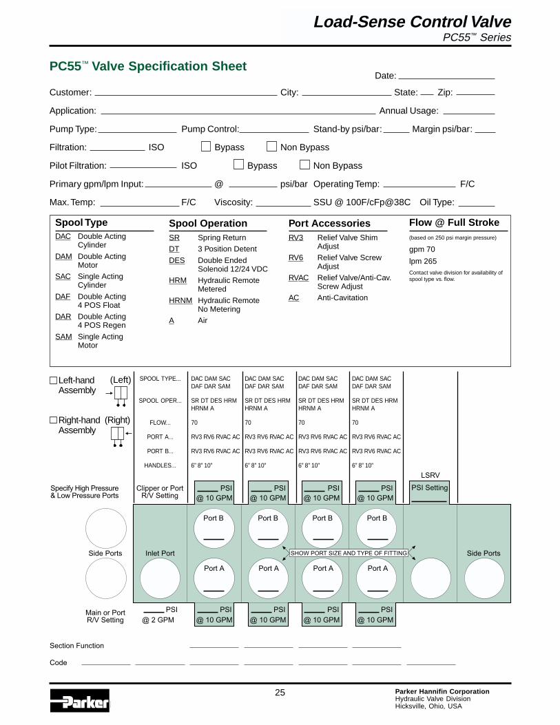
Customer: City: State: Zip:
Application: Annual Usage:
Pump Type: Pump Control: Stand-by psi/bar: Margin psi/bar:
Filtration: ISO Bypass Non Bypass
Pilot Filtration: ISO Bypass Non Bypass
Primary gpm/lpm Input: @ psi/bar Operating Temp: F/C
Max. Temp: F/C Viscosity: SSU @ 100F/cFp@38C Oil Type:
Spool TypeDAC Double Acting
Cylinder
DAM Double ActingMotor
SAC Single ActingCylinder
DAF Double Acting4 POS Float
DAR Double Acting4 POS Regen
SAM Single ActingMotor
Spool OperationSR Spring Return
DT 3 Position Detent
DES Double EndedSolenoid 12/24 VDC
HRM Hydraulic RemoteMetered
HRNM Hydraulic RemoteNo Metering
A Air
Port AccessoriesRV3 Relief Valve Shim
Adjust
RV6 Relief Valve ScrewAdjust
RVAC Relief Valve/Anti-Cav.Screw Adjust
AC Anti-Cavitation
��#��$����
��#��$����
��#��$����
��#��$����
��#��$����
��#��$����
��#��$����
��#��$����
��#� ����
�%�&��'���'��(���)���&*
�����)'��'���'��(���)���&*
��+)���'�, ��+)���'�,�-�!����� �.� ��� �/�����������
��)0�1 -�*2 �'),,�')3 ��4 �'),,�') ��'�,
�)0���&���&0���&
��+)
&�)����'�
����
����)���&*
��'���
��'��5
��'���
��'��5
��'���
��'��5
��'���
��'��5
SPOOL TYPE... DAC DAM SAC DAC DAM SAC DAC DAM SAC DAC DAM SACDAF DAR SAM DAF DAR SAM DAF DAR SAM DAF DAR SAM
SPOOL OPER... SR DT DES HRM SR DT DES HRM SR DT DES HRM SR DT DES HRMHRNM A HRNM A HRNM A HRNM A
FLOW... 70 70 70 70
PORT A... RV3 RV6 RVAC AC RV3 RV6 RVAC AC RV3 RV6 RVAC AC RV3 RV6 RVAC AC
PORT B... RV3 RV6 RVAC AC RV3 RV6 RVAC AC RV3 RV6 RVAC AC RV3 RV6 RVAC AC
HANDLES... 6” 8” 10” 6” 8” 10” 6” 8” 10” 6” 8” 10”
Date:PC55™ Valve Specification Sheet
Flow @ Full Stroke(based on 250 psi margin pressure)
gpm 70
lpm 265Contact valve division for availability ofspool type vs. flow.
Left-handAssembly
Right-handAssembly
(Left)
(Right)
Load-Sense Control ValvePC55™ Series
Load-Sense Control ValvePC25™/PC55™ Series
26 Parker Hannifin CorporationHydraulic Valve DivisionHicksville, Ohio, USA
Offer of SaleThe items described in this document are hereby offered for sale at prices to be established by Parker Hannifin Corporation, its subsidiaries and itsauthorized distributors. This offer and its acceptance by any customer (“Buyer”) shall be governed by all of the following Terms and Conditions. Buyer’s orderfor any item described in its document, when communicated to Parker Hannifin Corporation, its subsidiary or an authorized distributor (“Seller”) verbally or inwriting, shall constitute acceptance of this offer.
1. Terms and Conditions of Sale: All descriptions, quotations, proposals,offers, acknowledgments, acceptances and sales of Seller’s products aresubject to and shall be governed exclusively by the terms and conditionsstated herein. Buyer’s acceptance of any offer to sell is limited to these termsand conditions. Any terms or conditions in addition to, or inconsistent withthose stated herein, proposed by Buyer in any acceptance of an offer bySeller, are hereby objected to. No such additional, different or inconsistentterms and conditions shall become part of the contract between Buyer andSeller unless expressly accepted in writing by Seller. Seller’s acceptance ofany offer to purchase by Buyer is expressly conditional upon Buyer’s assentto all the terms and conditions stated herein, including any terms in additionto, or inconsistent with those contained in Buyer’s offer. Acceptance ofSeller’s products shall in all events constitute such assent.
2. Payment: Payment shall be made by Buyer net 30 days from the dateof delivery of the items purchased hereunder. Any claims by Buyer foromissions or shortages in a shipment shall be waived unless Seller receivesnotice thereof within 30 days after Buyer’s receipt of the shipment.
3. Delivery: Unless otherwise provided on the face hereof, delivery shall bemade F.O.B. Seller’s plant. Regardless of the method of delivery, however,risk of loss shall pass to Buyer upon Seller’s delivery to a carrier. Anydelivery dates shown are approximate only and Seller shall have no liabilityfor any delays in delivery.
4. Warranty: Seller warrants that the item sold hereunder shall be free fromdefects in material or workmanship for a period of 547 days from the date ofshipment to Buyer, or 3,000 hours of use, whichever expires first. THISWARRANTY COMPRISES THE SOLE AND ENTIRE WARRANTYPERTAINING TO ITEMS PROVIDED HEREUNDER. SELLER MAKES NOOTHER WARRANTY, GUARANTEE, OR REPRESENTATION OF ANYKIND WHATSOEVER. ALL OTHER WARRANTIES, INCLUDING BUT NOTLIMITED TO, MERCHANTABILITY AND FITNESS FOR PURPOSE,WHETHER EXPRESS, IMPLIED, OR ARISING BY OPERATION OF LAW,TRADE USAGE, OR COURSE OF DEALING ARE HEREBY DISCLAIMED.
NOTWITHSTANDING THE FOREGOING, THERE ARE NO WARRANTIESWHATSOEVER ON ITEMS BUILT OR ACQUIRED WHOLLY OR PAR-TIALLY, TO BUYERS DESIGNS OR SPECIFICATIONS.
5. Limitation of Remedy: SELLER’S LIABILITY ARISING FROM OR INANY WAY CONNECTED WITH THE ITEMS SOLD OR THIS CONTRACTSHALL BE LIMITED EXCLUSIVELY TO REPAIR OR REPLACEMENT OFTHE ITEMS SOLD OR REFUND OF THE PURCHASE PRICE PAID BYBUYER, AT SELLER’S SOLE OPTION IN NO EVENT SHALL SELLER BELIABLE FOR ANY INCIDENTAL OR SEQUENTIAL OR SPECIALDAMAGES OF ANY KIND OR NATURE WHATSOEVER, INCLUDING BUTNOT LIMITED TO LOST PROFITS ARISING FROM OR IN ANY WAYCONNECTED WITH THIS AGREEMENT OR ITEM SOLD HEREUNDER,WHETHER ALLEGED TO ARISE FROM BREACH OF CONTRACT,EXPRESS OR IMPLIED WARRANTY, OR IN TORT, INCLUDING WITHOUTLIMITATION, NEGLIGENCE, FAILURE TO WARN OR STRICT LIABILITY.
6. Changes, Reschedules and Cancellations: Buyer may request to modifythe designs or specifications for the items sold hereunder as well as thequantities and delivery dates thereof, or may request to cancel all or part ofthis order, however, no such requested modification or cancellation shallbecome part of the contract between Buyer and Seller unless accepted bySeller in a written amendment to this Agreement. Acceptance of any suchrequested modification or cancellation shall be at Seller’s discretion, andshall be upon such terms and conditions as Seller may require.
7. Special Tooling: A tooling charge may be imposed for any special tooling,including without limitation, dies, fixtures, molds and patterns, acquired tomanufacture items sold pursuant to this contract. Such special tooling shallbe and remain Seller’s property notwithstanding payment of any charges byBuyer. In no event will Buyer acquire any interest in apparatus belonging toSeller which is utilized in the manufacture of the items sold hereunder, even ifsuch apparatus has been specially converted or adapted for such manufac-ture and notwithstanding any charges paid by Buyer. Unless otherwiseagreed, Seller shall have the right to alter, discard or otherwise dispose ofany special tooling or other property in its sole discretion at any time.
8. Buyer’s Property: Any designs, tools, patterns, materials, drawings,confidential information or equipment furnished by Buyer or any other itemswhich become Buyer’s property, may be considered obsolete and may bedestroyed by Seller after two (2) consecutive years have elapsed withoutBuyer placing an order for the items which are manufactured using suchproperty. Seller shall not be responsible for any loss or damage to suchproperty while it is in Seller’s possession or control.
9. Taxes: Unless otherwise indicated on the face hereof, all prices andcharges are exclusive of excise, sales, use, property, occupational or liketaxes which may be imposed by any taxing authority upon the manufacture,sale or delivery of the items sold hereunder. If any such taxes must be paidby Seller or if Seller is liable for the collection of such tax, the amount thereofshall be in addition to the amounts for the items sold. Buyer agrees to pay allsuch taxes or to reimburse Seller therefore upon receipt of its invoice. IfBuyer claims exemption from any sales, use or other tax imposed by anytaxing authority, Buyer shall save Seller harmless from and against any suchtax, together with any interest or penalties thereon which may be assessed ifthe items are held to be taxable.
10. Indemnity For Infringement of Intellectual Property Rights: Sellershall have no liability for infringement of any patents, trademarks, copyrights,trade dress, trade secrets or similar rights except as provided in this Part 10.Seller will defend and indemnify Buyer against allegations of infringement ofU.S. patents, U.S. trademarks, copyrights, trade dress and trade secrets(hereinafter ‘Intellectual Property Rights’). Seller will defend at its expenseand will pay the cost of any settlement or damages awarded in an actionbrought against Buyer based on an allegation that an item sold pursuant tothis contract infringes the Intellectual Property Rights of a third party. Seller’sobligation to defend and indemnify Buyer is contingent on Buyer notifyingSeller within ten (10) days after Buyer becomes aware of such allegations ofinfringement, and Seller having sole control over the defense of anyallegations or actions including all negotiations for settlement or compromise.If an item sold hereunder is subject to a claim that it infringes the IntellectualProperty Rights of a third party, Seller may, at its sole expense and option,procure for Buyer the right to continue using said item, replace or modify saidtime so as to make it noninfringing, or offer to accept return of said item andreturn the purchase price less a reasonable allowance for depreciation.Notwithstanding the foregoing Seller shall have no liability for claims ofinfringement based on information provided by Buyer, or directed to itemsdelivered hereunder for which the designs are specified in whole or part byBuyer, or infringements resulting from the modification, combination or use ina system of any item sold hereunder. The foregoing provisions of this Part 10shall constitute Seller’s sole and exclusive liability and Buyer’s sole andexclusive remedy for infringement of Intellectual Property Rights.
If a claim is based on information provided by Buyer or if the design for anitem delivered hereunder is specified in whole or in part by Buyer, Buyer shalldefend and indemnify Seller for all costs, expenses or judgments resultingfrom any claim that such item infringes any patent, trademark, copyright,trade dress, trade secret or any similar right.
11. Force Majeure: Seller does not assume the risk of and shall not beliable for delay or failure to perform any of Seller’s obligations by reason ofcircumstances beyond the reasonable control of Seller (hereinafter ‘Eventsof Force Majeure’). Events of Force Majeure shall include without limitation,accidents, acts of God, strikes or labor disputes, acts, laws, rules orregulations of any government or government agency, fires, floods, delaysor failures in delivery of carriers or suppliers, shortages of materials andany other cause beyond Seller’s control.
12. Entire Agreement/Governing Law: The terms and conditions set forthherein, together with any amendments, modifications and any different termsor conditions expressly accepted by Seller in writing, shall constitute theentire Agreement concerning the items sold, and there are no oral or otherrepresentations or agreements which pertain thereto. This Agreement shallbe governed in all respects by the law of the State of Ohio. No actions arisingout of the sale of the items sold hereunder or this Agreement may be broughtby either party more than two (2) years after the cause of action accrues.
Load-Sense Control ValvePC25™/PC55™ Series
27 Parker Hannifin CorporationHydraulic Valve DivisionHicksville, Ohio, USA
The Aerospace Groupis a leader in the development,design, manufacture andservicing of control systemsand components for aerospaceand related high-technologymarkets, while achievinggrowth through premiercustomer service.
The Fluid ConnectorsGroup designs, manufacturesand markets rigid and flexibleconnectors, and associatedproducts used in pneumaticand fluid systems.
The Hydraulics Groupdesigns, produces andmarkets a full spectrumof hydraulic compnentsand systems to buildersand users of industrialand mobile machineryand equipment.
The Automation Groupis a leading supplier ofpneu-matic and electro-mechanical componentsand systems to automationcustomers worldwide.
The Climate & IndustrialControls Groupdesigns, manufactures andmarkets system-control andfluid-handling componentsand systems to refrigeration,air-conditioning and industrialcustomers worldwide.
The Seal Group designs,manufactures and distributesindustrial and commercialsealing devices and relatedproducts by providingsuperior quality andtotal customer satisfaction.
The Filtration Groupdesigns, manufactures andmarkets quality filtrationand clarification products,providing customers withthe best value, quality,technical support, andglobal availability.
The InstrumentationGroup is a global leaderin the design, manufactureand distribution of high-quality critical flowcomponents for worldwideprocessinstrumentation,ultra-high-purity, medicaland analytical applications.
Parker’s CharterTo be a leading worldwide manufacturer of componentsand systems for the builders and users of durablegoods. More specifically, we will design, market andmanufacture products controlling motion, flow andpressure. We will achieve profitable growth throughpremier customer service.
Product InformationNorth American customers seeking product information,the location of a nearby distributor, or repair serviceswill receive prompt attention by calling the ParkerProduct Information Center at our toll-free number:1-800-C-PARKER (1-800-272-7537). In the UK, a similarservice is available by calling 0500-103-203.
About Parker Hannifin CorporationParker Hannifin is a leading global motion-controlcompany dedicated to delivering premier customerservice. A Fortune 500 corporation listed on theNew York Stock Exchange (PH), our componentsand systems comprise over 1,400 product lines thatcontrol motion in some 1,000 industrial and aerospacemarkets. Parker is the only manufacturer to offer itscustomers a choice of hydraulic, pneumatic, andelectromechanical motion-control solutions. OurCompany has the largest distribution network in itsfield, with over 7,500 distributors serving more than350,000 customers worldwide.
Parker Hannifin Corporation6035 Parkland Blvd.Cleveland, Ohio 44124-4141Telephone: (216) 896-3000Fax: (216) 896-4000Web site: www.parker.com
Parker Hannifin Corporation

Catalog HY14-2002/US05/01, T&M, 5M
Parker Hannifin CorporationHydraulic Valve Division373 Meuse ArgonneHicksville, Ohio 43526 USATel: (419) 542-6611Fax: (419) 542-8871http://www.parker.com/hydraulicvalve