lnl iron baluster installation wood - the home depot · 1. a firm twist of the baluster may be all...
TRANSCRIPT

SUREWOOD
~ LNL
Po
st-to
-P
ost
A “
How
-To”
Guid
e for
the
inst
alla
tion o
f iro
n b
alu
sters
.
Iro
n B
alu
ste
r I
nsta
lla
tio
n
Tre
ad
an
d R
ise
r In
sta
lla
tio
n:
Bef
ore
prec
edin
g w
ith th
e fo
llow
ing
step
s, th
e ha
ndra
il he
ight
sho
uld
alre
ady
be d
eter
min
ed.
Rea
d al
l th
e st
eps
belo
w b
efor
e be
ginn
ing
inst
alla
tion.
Che
ck o
ut o
ur “
How
-To
Bui
ld a
St
airc
ase
Like
a P
ro” f
old
out b
roch
ure
or w
ww
.sur
e-w
ood.
com
for m
ore
deta
iled
inst
alla
tion
inst
ruct
ions
.
Ba
sic
La
yo
ut:
1
Po
st-to
-P
ost
Ove
r-th
e-P
ost
Wall
Rail
Leve
l Run
Hand
rail
Rose
tte
Land
ing
New
el
Post
Rad
ius
End
Sta
rtin
g S
tep
Rake
Hand
rail
Wall
Rail
Leve
l Run
Hand
rail
Ro
sett
e
Pin
To
p
Balu
sters
Rake
H
and
rail New
el
2
Po
st-to
-P
ost
Ove
r-th
e-P
ost
3
Nosin
g Ove
rhang
equa
ls the
tread
thick
ness
Po
st-to
-P
ost
Ove
r-th
e-P
ost
4
Ne
we
l P
ost
Insta
lla
tio
n:
Asse
mb
le t
he
Ha
nd
rail:
Ra
il B
olt
In
sta
lla
tio
n
Rail
Bo
lt
15
/16
”
1/4
”Dia
.H
ole
1”
Dia
.H
ole
1 3
/8”
2 1
/8”
3/8
” D
ia.
Ho
le
Nut
&W
ash
er
Me
asu
re a
nd
Tri
m N
ew
el P
osts
Usi
ng n
ewel
s as
gui
des,
mar
k ha
ndra
il
and
cut t
o pr
oper
leng
th. F
ollo
w
inst
ruct
ions
for a
ttach
ing
new
els
and
tem
pora
rily
inst
all h
andr
ail.
Usi
ng a
plu
m b
ob, l
ine
up w
ith
the
hole
s in
the
tread
s an
d m
ark
the
hand
rail
for t
he to
p of
the
balu
ster
. Dril
l hol
es u
sing
5/8
"
drill
bit a
min
imum
of 3
/4"
deep
into
han
drai
l.
Mar
k ba
lust
er p
lace
men
t on
tread
s al
low
ing
for e
qual
spa
cing
whi
le fo
llow
ing
your
or
igin
al d
esig
n. D
rill h
oles
* usi
ng 5
/8"
drill
bit a
min
imum
of 3
/4"
deep
into
sta
ir tre
ads.
Mak
e su
re to
kee
p th
e de
pths
con
sist
ent.
Mark
and
C
ut
Here
Me
asu
re a
nd
Tri
m B
alu
ste
rs
5Tri
m a
nd
In
sta
ll B
alu
ste
rs
The r
ake r
ail
heig
ht
should
be b
etw
een
36”–
42”
(H1) (c
heck local b
uild
ing c
od
es)
. C
ente
r th
e a
ssem
ble
d h
and
rail
ove
r th
enew
el lo
catio
ns.
Measu
re t
he d
ista
nce
betw
een t
he t
read
and
the b
ott
om
of
the h
and
rail
fittin
g (A
1 a
nd
A2). A
lso
measu
re t
he r
ake r
ail
thic
kness
(T1).
Use
the f
ollo
win
g f
orm
ula
to c
alc
ula
te
the s
tart
ing n
ew
el heig
ht.
If th
e n
ew
el st
art
s from
the f
loor
or
a low
er
tread
, ad
d t
hat
dis
tance
as
well.
36” to
41”
abov
e fro
nt ed
ge
of tre
ad
Appl
y gl
ue to
end
s.
Asse
mbl
e an
d in
stal
l nu
t. Ti
ghte
n nu
t with
w
renc
h. F
ill ac
cess
ho
le w
ith w
ood
plug
.
Asse
mbl
e th
e ha
ndra
il on
top
of
the
stai
r tre
ads
prio
r to
inst
allin
g th
e ne
wel
pos
ts. U
se ra
il bo
lts a
nd
glue
at e
ach
fittin
g co
nnec
tion.
C
ompl
ete
inst
ruct
ions
are
incl
uded
w
ith fi
tting
s.
Mark
Positi
on of
La
nding
New
el an
d Ce
nter-li
ne
Balus
ter C
enter
-line
Startin
g New
el
Mark
Positi
on of
Ba
luster
Cen
ter-po
int*
Face
of St
ringe
r
Marki
ng Yo
ur St
airca
se fo
r Insta
llatio
nLa
yout
you
r sta
ircas
e di
rect
ly on
you
r tre
ads
and
land
ings
. C
aref
ully
mar
k N
ewel
and
Bal
uste
r pos
itions
and
cen
ter-l
ines
.
Mark
Positi
on of
La
nding
New
el an
d Cen
ter-lin
e
Balus
ter C
enter
-line
Face
of St
ringe
r
Mark
Positi
on of
Ba
luster
Cen
ter-po
int*
Startin
g New
el Start
ing Ea
sing F
itting
Layo
utTu
rnou
t Star
ting F
itting
Layo
ut
The b
alustr
ade
cente
r-line
and n
ewel
cente
r-poin
ts sh
ould
be
laid o
ut. O
n a kn
ee-w
all
stair,
the ba
lustra
de
shou
ld be
cente
red
on th
e kne
e-wa
ll. On
an
open
-trea
d stai
r, the
cente
r-line
shou
ld be
1/2 o
f the b
aluste
r sq
uare
in fro
m the
face
of
the st
ringe
r (i.e.
5/8”
for
a 1-
1/4”
balus
ter).
To p
rope
rly in
stal
l sol
id o
ak tr
eads
and
rise
rs, y
ou m
ust f
irst r
emov
e th
e ex
istin
g st
eps
to
expo
se th
e ro
ugh
fram
ing.
Lea
ve th
e be
ginn
ing
riser
at b
ase
of s
teps
(A).
Mea
sure
and
cu
t eac
h st
ep s
epar
atel
y to
ens
ure
tight
fit.
(B).
Pre-
drill,
app
ly co
nstru
ctio
n ad
hesiv
e an
d na
il int
o pl
ace.
For
add
ed s
treng
th, s
crew
trea
ds to
rise
rs fr
om b
ehin
d (C
). C
ompl
ete
each
st
ep b
efor
e co
ntin
uing
on
to n
ext s
tep.
AB
C
A) H
eigh
t of t
he
hand
rail
shou
ld b
e
betw
een
36”
and
42".
Che
ck lo
cal
build
ing
code
s.
B) P
lace
the
top
of th
e ha
ndra
il on
e
inch
bel
ow th
e to
p
bloc
k of
the
new
el.
36"
to
42"
abov
e fro
nt o
f tre
ad
1" fr
om to
p of
sq
uare
par
t of
new
el
*Check lo
cal b
uild
ing c
od
es
for
pro
per
hand
rail
heig
ht.
Lag
Bol
tsJ-
Anch
or
with
Mol
ding
Woo
d Pl
ugs
Sta
rtin
g N
ew
el H
eig
ht
B
With
new
el in
posit
ion w
here
it is
to b
e m
ount
ed, s
lide
shor
t end
of f
ram
ing s
quar
e alo
ng
slope
of s
tairw
ay.
A) S
lide
into
post
as
show
n. M
ake
mar
k.B)
Mea
sure
dow
n 1"
from
top
of n
ewel
squa
re. M
ake
mar
k.
C) T
he d
iffere
nce
betw
een
the
two
mar
ks "A
" and
"B" i
s wh
at
will b
e cu
t off
botto
m o
f new
el.
Proc
eed
with
new
el ins
talla
tion.
La
nd
ing
Ne
we
l H
eig
ht
AB
Newe
l Pos
t Atta
chme
ntTr
im a
nd F
aste
n th
e N
ewel
Pos
ts u
sing
on
e of
thes
e m
etho
ds
Follo
w th
e in
stru
ctio
n on
the
othe
r sid
e of
this
bro
chur
e to
trim
and
inst
all y
our I
ron
balu
ster
s.
EZ
Lo
ck
New
el
Post
Pla
te
Fast
ener
101
Sure
-Tite
New
el
Fast
ener
Ke
ylo
ck
New
el P
ost
Fast
ener
H1
+ A
1 –
T1
= S
tart
ing
Ne
we
l H
eig
ht
3N
ew
el P
ost
Insta
lla
tio
n:
A C
Iro
n B
alu
ste
r In
sta
lla
tio
n
*Meta
l balu
sters
shou
ld be
insta
lled no
wide
r than
4”
on ce
nter, s
o tha
t a 4”
sphe
re ca
nnot
pass
throu
gh
anyw
here
along
the h
andra
il. Ch
eck y
our lo
cal
buildi
ng co
des t
o ens
ure co
mplian
ce.
*Not
e:
a. 1
/2”
balu
ster
s re
quire
5/8
” ho
les.
b.
5/8
” ba
lust
ers
requ
ire 7
/8”
hole
s.
1.
A firm
tw
ist
of th
e b
alu
ster
may
be a
ll th
at
is n
ecess
ary
to
rem
ove
balu
ster
from
tr
ead
and
hand
rail.
Rem
ove
any
nails
rem
ain
ing o
r fa
steners
.
2.
Once lo
ose
ned
, lif
t th
e
balu
ster
up
into
the h
and
rail,
enough t
o c
lear
the s
tair
tread
at
the b
ott
om
, and
th
en t
ilt it
to t
he s
ide a
nd
pull
out
from
the h
and
rail.
1.
Cut
balu
ster
in h
alf
with
a
hand
or
pow
er
saw
.
2.
Twis
t each h
alf
to lo
ose
n.
3.
Rem
ove
each h
alf
of th
e
balu
ster
from
the s
tair t
read
and
hand
rail,
and
any
nails
re
main
ing o
r fa
steners
.
4.
If glu
e a
nd
/or
wood
stil
l re
main
s in
the h
ole
s, a
d
rill
with
a 1
/2”
bit
can
be u
sed
to r
em
ove
any
exc
ess
.*
Fla
t S
hoe
Rake S
hoe
Ch
oo
se
yo
ur
loo
k .
..
*Check lo
cal b
uild
ing c
od
es
to e
nsu
re c
om
plia
nce
Re
pla
cin
g W
oo
d B
alu
ste
rs w
ith
Iro
n B
alu
ste
rs
1st
Me
tho
d:
Wood-to-Iron Retrofit in just a day!
Doub
le
Bask
et
Balu
ster
Sin
gle
B
ask
et
Balu
ster
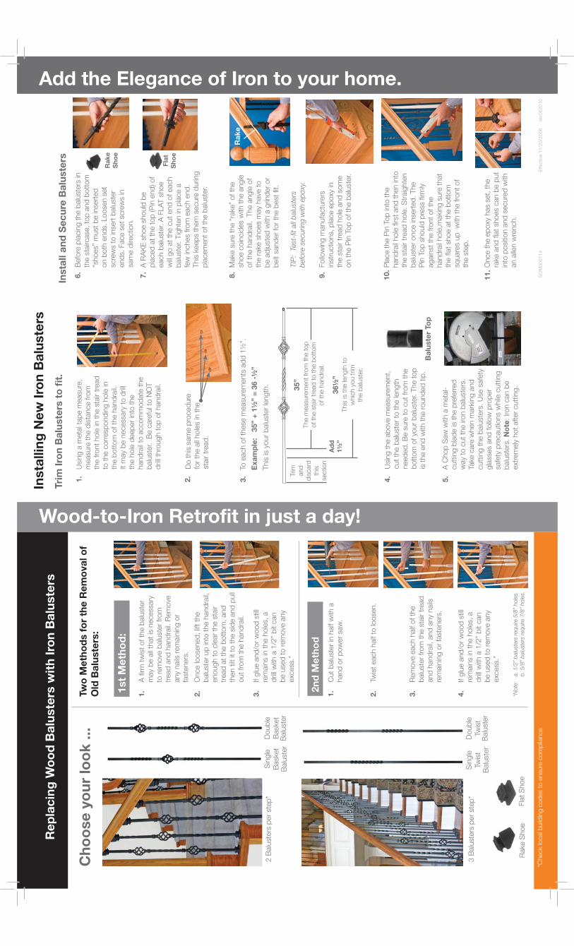
Add the Elegance of Iron to your home.Tri
m I
ron
Ba
luste
rs t
o fi
t.
Usi
ng a
meta
l tap
e m
easu
re,
measu
re t
he d
ista
nce fro
m
the fro
nt
hole
in t
he s
tair t
read
to
the c
orr
esp
ond
ing h
ole
in
the b
ott
om
of th
e h
and
rail.
It m
ay
be n
ecess
ary
to d
rill
the h
ole
deep
er
into
the
hand
rail
to a
ccom
mod
ate
the
balu
ster. B
e c
are
ful t
o N
OT
drill
thro
ugh t
op
of hand
rail.
Do t
his
sam
e p
roced
ure
fo
r th
e a
ll hole
s in
the
stair t
read
.
To e
ach o
f th
ese
measu
rem
ents
ad
d 1
½”.
Exa
mp
le: 35”
+ 1
½”
= 3
6 -
½”
This
is y
our
balu
ster
length
.
Usi
ng t
he a
bove
measu
rem
ent,
cut
the b
alu
ster
to t
he le
ngth
need
ed
. B
e s
ure
to c
ut
from
the
bott
om
of yo
ur
balu
ster. T
he t
op
is
the e
nd
with
the r
ound
ed
tip
.
A C
hop
Saw
with
a m
eta
l-cutt
ing b
lad
e is
the p
refe
rred
w
ay
to c
ut
the ir
on b
alu
sters
. Ta
ke c
are
when m
ark
ing a
nd
cutt
ing t
he b
alu
sters
. U
se s
afe
ty
gla
sses
and
follo
w p
rop
er
safe
ty p
recautio
ns
while
cutt
ing
balu
sters
. N
ote
: Iron c
an b
e
ext
rem
ely
hot
after
cutt
ing.
Fla
t S
ho
e
Ra
ke
Sh
oe
Ra
ke
1.
2.
3.
5.
4.
Befo
re p
lacin
g t
he b
alu
sters
in
the s
tairc
ase
, to
p a
nd
bott
om
“s
hoes”
must
be in
sert
ed
on b
oth
end
s. L
oose
n s
et
scre
ws
to in
sert
balu
ster
end
s. F
ace s
et
scre
ws
in
sam
e d
irectio
n.
6.
A R
AK
E s
hoe s
hould
be
pla
ced
at
the t
op
(P
in e
nd
) of
each b
alu
ster. A
FLA
T s
hoe
will g
o a
t th
e c
ut
end
of each
balu
ster. T
ighte
n in
pla
ce a
fe
w in
ches
from
each e
nd
. This
keep
s th
em
secure
during
pla
cem
ent
of th
e b
alu
ster.
7.
Make s
ure
the “
rake”
of th
e
shoe c
oin
cid
es
with
the a
ngle
of th
e h
and
rail.
The a
ngle
of
the r
ake s
hoes
may
have
to
be a
dju
sted
with
a g
rind
er
or
belt
sand
er
for
the b
est
fit.
TIP
: Te
st-f
it al
l bal
uste
rs
befo
re s
ecur
ing
with
epo
xy.
8.
Once t
he e
poxy
has
set,
the
rake a
nd
fla
t sh
oes
can b
e p
ut
into
posi
tion a
nd
secure
d w
ith
an a
llen w
rench.
11.
Pla
ce t
he P
in T
op
into
the
hand
rail
hole
first
and
then in
to
the s
tair t
read
hole
. S
traig
hte
n
balu
ster
once in
sert
ed
. The
Pin
Top
should
pre
ss firm
ly
again
st t
he fro
nt
of th
e
hand
rail
hole
,makin
g s
ure
that
the fla
t sh
oe a
t th
e b
ott
om
sq
uare
s up
w
ith t
he fro
nt
of
the s
tep
.
10.
Follo
win
g m
anufa
ctu
rers
in
stru
ctio
ns,
pla
ce e
poxy
in
the s
tair t
read
hole
and
som
e
on t
he P
in T
op
of th
e b
alu
ster.
9.
Tw
o M
eth
od
s f
or
the
Re
mo
va
l o
f O
ld B
alu
ste
rs:
Insta
llin
g N
ew
Iro
n B
alu
ste
rs
Doub
le
Twis
t B
alu
ster
Sin
gle
Tw
ist
Balu
ster
2n
d M
eth
od
3.
If glu
e a
nd
/or
wood
stil
l re
main
s in
the h
ole
s, a
d
rill
with
a 1
/2”
bit
can
be u
sed
to r
em
ove
any
exc
ess
.*
Insta
ll a
nd
Se
cu
re B
alu
ste
rs
2 B
alu
sters
per
step
*
3 B
alu
sters
per
step
*
Ba
luste
r To
p
35”
Ad
d
1½
”36½
”
Trim
and
d
iscard
th
is
sectio
n
The m
easu
rem
ent
from
the t
op
of th
e s
tair t
read
to t
he b
ott
om
of th
e h
and
rail.
This
is t
he le
ngth
to
whic
h y
ou t
rim
th
e b
alu
ster.
SO
M300114 E
ffectiv
e 1
1/2
0/2
006 r
ev0
62010
*Not
e:
a. 1
/2”
balu
ster
s re
quire
5/8
” ho
les.
b.
5/8
” ba
lust
ers
requ
ire 7
/8”
hole
s.