lmhc connectors - wealdelectronics.com · section of connectors 1 – fixed shell 2 – free inner...
TRANSCRIPT
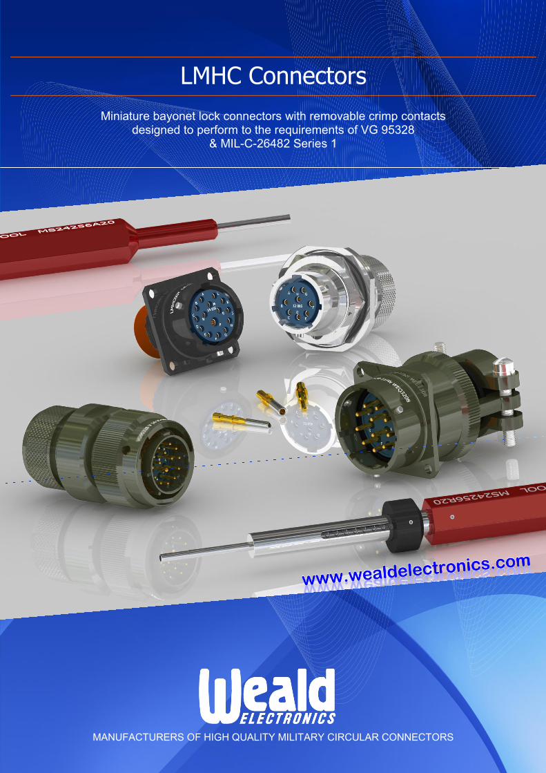
LMHC Connectors
MANUFACTURERS OF HIGH QUALITY MILITARY CIRCULAR CONNECTORS
Miniature bayonet lock connectors with removable crimp contacts designed to perform to the requirements of VG 95328
& MIL-C-26482 Series 1

2
This publication is issued to provide outline information only and unless specifically agreed to the contrary by WEALD ELECTRONICS LTD. in writing, is not to form part of any order or contract or be regarded as a representation relating to the products or services concerned.
WEALD ELECTRONICS LTD. reserve the right to alter without notice the product design, price or conditions of supply of any product or service. Whilst every effort has been made to ensure that the information contained in this catalogue is accurate, no responsibility can be accepted
for any errors or omissions nor for the effects of such errors or omissions.
www.wealdelectronics.com
LMHC RANGE CONTENTS
General Information
Description & Characteristics ……………………………………………………………………………………………………………………. 3, 4
Connector Styles ………………………………………………………………………………………………………………………………. 5, 6, 7
Contact Arrangements ……………………………………………………………………………………………………………………………… 8
Orientations (Inserts) …………………………………………………………………………………………………………………………….….. 9
Shell Polarisation …………………………………………………………………………………………………………………………………... 10
Ordering Information
LMHC Connectors – Weald Code ……………………………………………………………………………………………………… 11
LMA Accessories – Weald Code ……………………………………………………………………………………………………… 12
LMHC Connectors – VG Code …………………………………………………………………………………………………………. 13
LMA Accessories – VG Code …………………………………………………………………………………………………………. 14
Shell / Accessories – Possible Connections (Table) ………………………………………………………………………………… 15
Connector Dimensions
02A & 00T (VG Style – C) Fixed, square flange mounting, with or without accessory thread ……………………………………………. 16
07A & 07T Fixed, single hole mounting with ‘O’ ring panel seal, with or without accessory thread ……………………. 17
06T, 06TG, 06E, 06EG, 46T, 46TG, 46E, 46EG
Free with fine knurled or coarse ribbed coupling nut with accessories ………………………………………. 18
00E (VG Style – A) & 00F (VG Style – B)
Fixed, square flange mounting with grommet nut or cable clamp ……………………………………………. 19
06MG (VG Style – M) & 00R (VG Style – R)
Free or fixed, with heat shrink boot adaptor for shielded-conductor cable …………………………………... 20
06VG (VG Style – V) Free, fine knurled coupling nut with grounding fingers and heat shrink boot adaptor ……………………… 21
06F (VG Style – K), 06FG, 46F, 46FG
Free with fine knurled or coarse ribbed coupling nut, with or without grounding fingers with clamp ……... 22
07E (VG Style – D) & 07F (VG Style – E)
Fixed, single hole mounting with ‘O’ ring panel seal and grommet nut or cable clamp …………………….. 23
07S (VG Style – S) Fixed, single hole mounting with ‘O’ ring panel seal and heat shrink boot adaptor ………………………… 24
Accessories
LMA Protective Caps ………………………………………………………………………………………………………………………………. 25
Contacts Information
Contacts …..………………………………………………………………………………………………………………………………………… 26
Sealing Plugs ……………………………………………………………………………………………………………………………………….. 26
Assembly Instructions
Wire Stripping & Crimping Wire to Contact ……………………………………………………………………………………………………… 27
Contact Insertion …………………………………………………………………………………………………………………………………… 28
Contact Removal …………………………………………………………………………………………………………………………………... 29
Fixing of Shielded-Conductor Cable to Connectors with Heat Shrink Boot Adaptor ……………………………………………………….. 30
Panel Piercing Data ………………………………………………………………………………………………………………………………... 31
Product Safety Information…………………………………………….………………………………………………...……...……………… 32
3
FOR SALES ENQUIRIES CONTACT F.C. LANE ELECTRONICS LTD TEL: 01403 790661 FAX: 01403 790849 E-mail: [email protected]
FOR TECHNICAL ENQUIRIES CONTACT WEALD ELECTRONICS LTD TEL: 01403 790715 FAX: 01403 790734 E-mail: [email protected]
www.wealdelectronics.com
LMHC RANGE
DESCRIPTION & CHARACTERISTICS
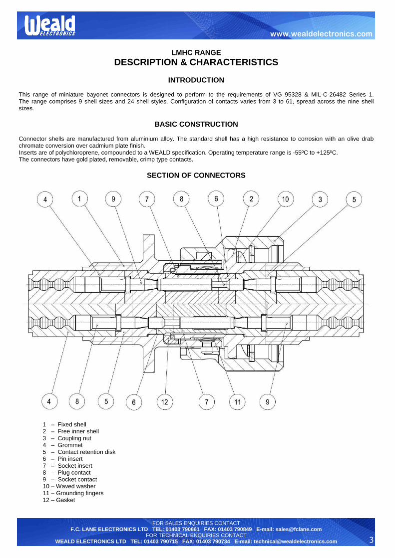
INTRODUCTION This range of miniature bayonet connectors is designed to perform to the requirements of VG 95328 & MIL-C-26482 Series 1. The range comprises 9 shell sizes and 24 shell styles. Configuration of contacts varies from 3 to 61, spread across the nine shell sizes.
BASIC CONSTRUCTION
Connector shells are manufactured from aluminium alloy. The standard shell has a high resistance to corrosion with an olive drab chromate conversion over cadmium plate finish. Inserts are of polychloroprene, compounded to a WEALD specification. Operating temperature range is -55ºC to +125ºC. The connectors have gold plated, removable, crimp type contacts.
SECTION OF CONNECTORS
1 – Fixed shell 2 – Free inner shell 3 – Coupling nut 4 – Grommet 5 – Contact retention disk 6 – Pin insert 7 – Socket insert 8 – Plug contact 9 – Socket contact 10 – Waved washer 11 – Grounding fingers 12 – Gasket

4
FOR SALES ENQUIRIES CONTACT F.C. LANE ELECTRONICS LTD TEL: 01403 790661 FAX: 01403 790849 E-mail: [email protected]
FOR TECHNICAL ENQUIRIES CONTACT WEALD ELECTRONICS LTD TEL: 01403 790715 FAX: 01403 790734 E-mail: [email protected]
www.wealdelectronics.com
LMHC RANGE
GENERAL INFORMATION
EMC SCREENING To satisfy electromagnetic compatibility (EMC) and electromagnetic pulse (EMP) requirements, free shells can be fitted with grounding fingers. Fixed & free shells can be fitted with accessories for screened cable terminations.
POLARISATION To avoid mis-mating with similar connectors which may be adjacently mounted, LMHC connectors may be polarised thus:
a) Angular Disposition of the Inserts within the Shell providing up to four different orientations other than Normal (N). These are designated W, X, Y, Z. See Table on page 9 for variations available in each planform, or;
b) The Position of Shell Keys and Keyways providing up to four different polarisations other than normal (N). These are designated B, C, E, F (see page 10). With these variations, inserts can be supplied only with the Normal (N) position.
LMHC STANDARD CHARACTERISTICS Environmental Category – 55/125/56 Low pressure severity – 44 millibars Number of Contacts – 3 to 61 Contact Termination – Crimp Maximum Current Rating at 85ºC:
a) per individual contact in isolation – Size 20 – 7,5 amp – Size 16 – 13,0 amps
b) per contact through all contacts simultaneously – Size 20 – 5,0 amp – Size 16 – 10,0 amps
Contact Finish – Gold Plated Working Voltage DC or AC Peak (at sea level) – 700 volts or 1200 volts Sealing – Environment Resistant with barrier or barrier and panel seal *Housing (Shell) Material – Aluminium Alloy *Housing (Shell) Finish – Olive drab chromate conversion over cadmium plate *Housing (Shell) – Other materials and finishes available. Please consult Sales.

5
FOR SALES ENQUIRIES CONTACT F.C. LANE ELECTRONICS LTD TEL: 01403 790661 FAX: 01403 790849 E-mail: [email protected]
FOR TECHNICAL ENQUIRIES CONTACT WEALD ELECTRONICS LTD TEL: 01403 790715 FAX: 01403 790734 E-mail: [email protected]
www.wealdelectronics.com
LMHC RANGE
SHELL STYLES AVAILABLE
Style 00E (A*) Fixed, square flange mounting with grommet nut
See page 19
Mates with
styles 06 46
Style 00F (B*) Fixed, square flange mounting with cable clamp
See page 19
Mates with
styles 06 46
Style 00R (R*) Fixed, square flange mounting with heat shrink boot adaptor for shielded-conductor cable
See page 20
Mates with
styles 06 46
Style 00T Fixed, square flange mounting with accessory thread
See page 16
Mates with styles
06 46
Style 02A (C*) Fixed, square flange mounting without accessory thread
See page 16
Mates with styles
06 46
Style 06E Free, fine knurled coupling nut with grommet nut Style 06EG Free, fine knurled coupling nut with grommet nut and grounding fingers
See page 18
Mates with styles
00 02 07
* - VG Style in brackets
6
FOR SALES ENQUIRIES CONTACT F.C. LANE ELECTRONICS LTD TEL: 01403 790661 FAX: 01403 790849 E-mail: [email protected]
FOR TECHNICAL ENQUIRIES CONTACT WEALD ELECTRONICS LTD TEL: 01403 790715 FAX: 01403 790734 E-mail: [email protected]
www.wealdelectronics.com
LMHC RANGE
SHELL STYLES AVAILABLE
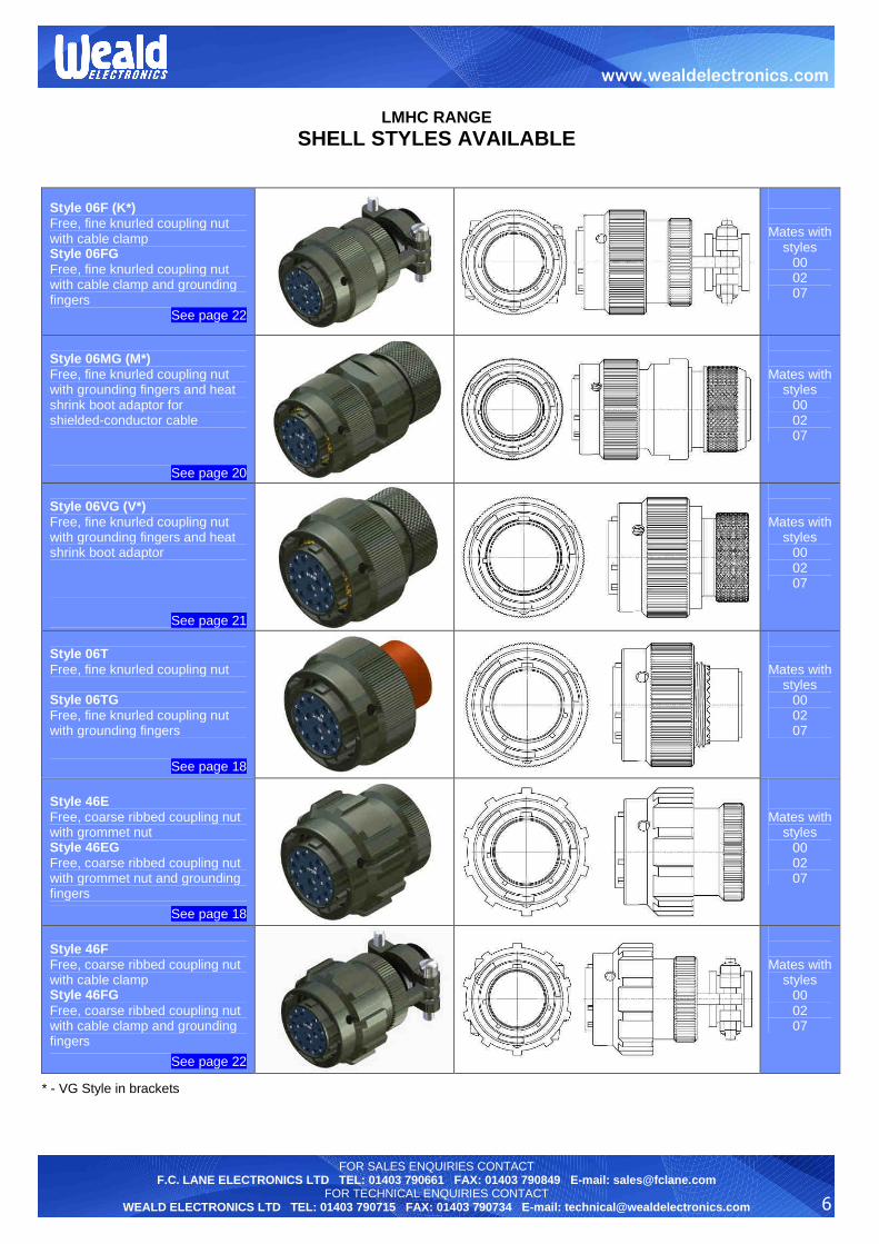
Style 06F (K*) Free, fine knurled coupling nut with cable clamp Style 06FG Free, fine knurled coupling nut with cable clamp and grounding fingers
See page 22
Mates with styles
00 02 07
Style 06MG (M*) Free, fine knurled coupling nut with grounding fingers and heat shrink boot adaptor for shielded-conductor cable
See page 20
Mates with styles
00 02 07
Style 06VG (V*) Free, fine knurled coupling nut with grounding fingers and heat shrink boot adaptor
See page 21
Mates with styles
00 02 07
Style 06T Free, fine knurled coupling nut Style 06TG Free, fine knurled coupling nut with grounding fingers
See page 18
Mates with styles
00 02 07
Style 46E Free, coarse ribbed coupling nut with grommet nut Style 46EG Free, coarse ribbed coupling nut with grommet nut and grounding fingers
See page 18
Mates with styles
00 02 07
Style 46F Free, coarse ribbed coupling nut with cable clamp Style 46FG Free, coarse ribbed coupling nut with cable clamp and grounding fingers
See page 22
Mates with styles
00 02 07
* - VG Style in brackets
7
FOR SALES ENQUIRIES CONTACT F.C. LANE ELECTRONICS LTD TEL: 01403 790661 FAX: 01403 790849 E-mail: [email protected]
FOR TECHNICAL ENQUIRIES CONTACT WEALD ELECTRONICS LTD TEL: 01403 790715 FAX: 01403 790734 E-mail: [email protected]
www.wealdelectronics.com
LMHC RANGE
SHELL STYLES AVAILABLE
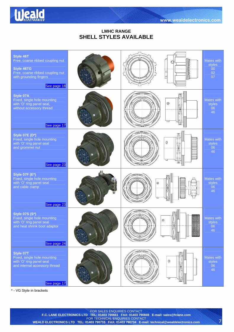
Style 46T Free, coarse ribbed coupling nut Style 46TG Free, coarse ribbed coupling nut with grounding fingers
See page 18
Mates with styles
00 02 07
Style 07A Fixed, single hole mounting with ‘O’ ring panel seal, without accessory thread
See page 17
Mates with styles
06 46
Style 07E (D*) Fixed, single hole mounting with ‘O’ ring panel seal and grommet nut
See page 23
Mates with styles
06 46
Style 07F (E*) Fixed, single hole mounting with ‘O’ ring panel seal and cable clamp
See page 23
Mates with styles
06 46
Style 07S (S*) Fixed, single hole mounting with ‘O’ ring panel seal and heat shrink boot adaptor
See page 24
Mates with styles
06 46
Style 07T Fixed, single hole mounting with ‘O’ ring panel seal and internal accessory thread
See page 17
Mates with styles
06 46
* - VG Style in brackets

8
FOR SALES ENQUIRIES CONTACT F.C. LANE ELECTRONICS LTD TEL: 01403 790661 FAX: 01403 790849 E-mail: [email protected]
FOR TECHNICAL ENQUIRIES CONTACT WEALD ELECTRONICS LTD TEL: 01403 790715 FAX: 01403 790734 E-mail: [email protected]
www.wealdelectronics.com
LMHC RANGE
CONTACT ARRANGEMENT AVAILABILITY
Number of contacts Shell size 2 3 4 5 6 7 8 10 11 12 15 16 19 21 23 26 32 39 41 55 61
08 08-3A 08-33 08-98
10 10-02 10-06 10-07
12 12-03 12-08 12-10
14 14-05 14-12 14-15 14-19
16 16-08 16-23 16-26
18 18-11 18-32
20 20-16 20-39 20-41
22 22-21 22-55
24 24-61
08-3A 08-33 08-98
10-02 10-06 10-07
12-03 12-08 12-10
14-05 14-12 14-15 14-19
16-08 16-23 16-26
18-11 18-32
20-16 20-39 20-41
22-21 22-55
24-61
Contact Weald Electronics
Technical Department
= size 20 contacts (voltage rating at sea level = 700V) = size 16 contacts (voltage rating at sea level = 1200V) Not to scale
Customer Layout
9
FOR SALES ENQUIRIES CONTACT F.C. LANE ELECTRONICS LTD TEL: 01403 790661 FAX: 01403 790849 E-mail: [email protected]
FOR TECHNICAL ENQUIRIES CONTACT WEALD ELECTRONICS LTD TEL: 01403 790715 FAX: 01403 790734 E-mail: [email protected]
www.wealdelectronics.com
LMHC RANGE
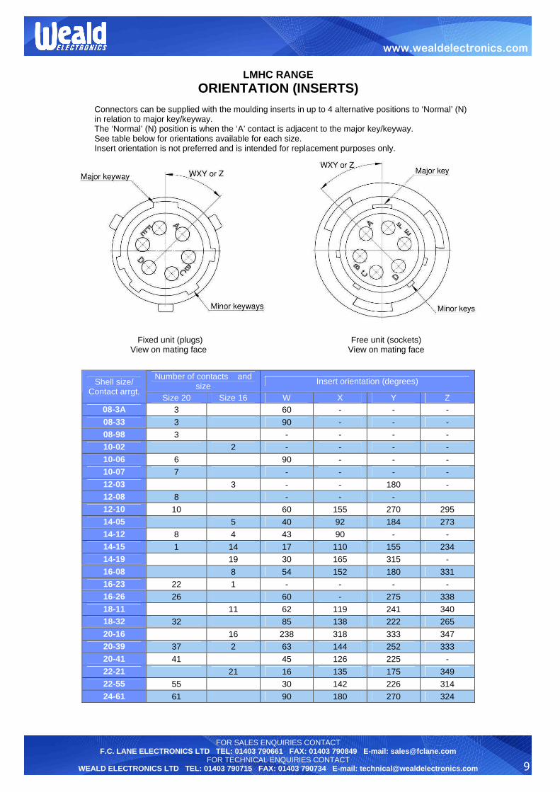
ORIENTATION (INSERTS)
Connectors can be supplied with the moulding inserts in up to 4 alternative positions to ‘Normal’ (N) in relation to major key/keyway. The ‘Normal’ (N) position is when the ‘A’ contact is adjacent to the major key/keyway. See table below for orientations available for each size. Insert orientation is not preferred and is intended for replacement purposes only.
Fixed unit (plugs) Free unit (sockets) View on mating face View on mating face
Number of contacts and size Insert orientation (degrees) Shell size/
Contact arrgt. Size 20 Size 16 W X Y Z
08-3A 3 60 - - -
08-33 3 90 - - - 08-98 3 - - - - 10-02 2 - - - -
10-06 6 90 - - - 10-07 7 - - - -
12-03 3 - - 180 - 12-08 8 - - - 12-10 10 60 155 270 295
14-05 5 40 92 184 273 14-12 8 4 43 90 - -
14-15 1 14 17 110 155 234 14-19 19 30 165 315 -
16-08 8 54 152 180 331 16-23 22 1 - - - - 16-26 26 60 - 275 338
18-11 11 62 119 241 340 18-32 32 85 138 222 265
20-16 16 238 318 333 347 20-39 37 2 63 144 252 333 20-41 41 45 126 225 -
22-21 21 16 135 175 349 22-55 55 30 142 226 314
24-61 61 90 180 270 324

10
FOR SALES ENQUIRIES CONTACT F.C. LANE ELECTRONICS LTD TEL: 01403 790661 FAX: 01403 790849 E-mail: [email protected]
FOR TECHNICAL ENQUIRIES CONTACT WEALD ELECTRONICS LTD TEL: 01403 790715 FAX: 01403 790734 E-mail: [email protected]
www.wealdelectronics.com
LMHC RANGE
SHELL POLARISATION
Key and keyways relate to free connectors respectively. The diagrams and table below show the angular versions of key/keyways for each polarisation in this connector range. The major key/keyway, shown on the vertical line, is the datum point.
Free unit Fixed unit View on mating face View on mating face
Orientations (A-A) Shell size Normal B C E F
08 105 - - 118 82
10 105 85 125 115 85
12 105 89 121 115 85
14 105 91 119 75 120
16 105 93 117 75 120
18 105 95 115 75 120
20 105 95 115 75 120
22 105 97 113 75 120
24 105 97 113 75 120

11
FOR SALES ENQUIRIES CONTACT F.C. LANE ELECTRONICS LTD TEL: 01403 790661 FAX: 01403 790849 E-mail: [email protected]
FOR TECHNICAL ENQUIRIES CONTACT WEALD ELECTRONICS LTD TEL: 01403 790715 FAX: 01403 790734 E-mail: [email protected]
www.wealdelectronics.com
LMHC RANGE
WEALD CODE ORDERING INFORMATION
CONNECTORS
EXAMPLE LMHC 06 E 16 23 P N 0
Range prefix
Shell style 00 – Fixed, square flange mounting with accessory thread 02 – Fixed, square flange mounting 06 – Free, fine knurled coupling nut 07 – Fixed, single hole mounting with panel seal 46 – Free, coarse ribbed coupling nut
Class A – Connector without accessory thread T – Connector without accessory fittings E – Connector with grommet nut F – Connector with cable clamp S – Connector with heat shrink boot adaptor R – Connector with heat shrink boot adaptor for shielded conductor cable VG – Connector with grounding fingers and heat shrink boot adaptor MG – Connector with grounding fingers and heat shrink boot adaptor for shielded conductor cable TG – Connector without accessory fittings, with grounding fingers EG – Connector with grommet nut and grounding fingers FG – Connector with cable clamp and grounding fingers
Shell size 08 - 24 inclusive in even number increments Represents dia. of female shell in 1.6mm steps
Variant 0 = No variant required 101 – Zinc cobalt, olive drab 102 – Electroless nickel Other variants available. Please contact Weald Electronics
Orientation/Polarisation N – Neutral (normal) orientation and polarisation W X Orientation by insert rotation – Y refer to page 9 Z B C Polarisation by relative displacement E of keys/keyways – refer to page 10 F
Contact P – Pin (male contact) S – Socket (female contact)
Contact arrangement – refer to page 8

12
FOR SALES ENQUIRIES CONTACT F.C. LANE ELECTRONICS LTD TEL: 01403 790661 FAX: 01403 790849 E-mail: [email protected]
FOR TECHNICAL ENQUIRIES CONTACT WEALD ELECTRONICS LTD TEL: 01403 790715 FAX: 01403 790734 E-mail: [email protected]
www.wealdelectronics.com
LMHC RANGE
WEALD CODE ORDERING INFORMATION
ACCESSORIES
EXAMPLE LMA 2200 16 00 00
Range prefix
1053 – Protective cap with cord for free connector 1054 – Protective cap with cord for square flange connector 1055 – Protective cap with cord for single hole mounting connector 1071 – Square flange mounting gasket (non electrically conductive) 2018 – Heat shrink boot adaptor for shells with external accessory thread (Styles: 00, 06, 46) 2200 – Heat shrink boot adaptor for shielded conductor cable and shells with external accessory thread (Styles: 00, 06, 46) 2201 – Cable clamp assembly for shells with external accessory thread (Styles: 00, 06, 46) 2202 – Grommet nut assembly for shells with external accessory thread (Styles: 00, 06, 46) 2204 – Cable clamp assembly for shells with internal accessory thread (Style: 07) 2205 – Grommet nut assembly for shells with internal accessory thread (Style: 07) 2206 – Heat shrink boot adaptor for shells with internal accessory thread (Style: 07) 8526 – Square flange mounting gasket (electrically conductive) 8527 – ‘O’ ring seal for single hole mounting connector (electrically conductive)
Shell size 08 - 24 inclusive in even number increments Represents dia. of female shell in 1.6mm steps
Variant 0 = No variant required 101 – Zinc cobalt, olive drab 102 – Electroless nickel Other variants available. Please contact Weald Electronics.
00 = No variant required

13
FOR SALES ENQUIRIES CONTACT F.C. LANE ELECTRONICS LTD TEL: 01403 790661 FAX: 01403 790849 E-mail: [email protected]
FOR TECHNICAL ENQUIRIES CONTACT WEALD ELECTRONICS LTD TEL: 01403 790715 FAX: 01403 790734 E-mail: [email protected]
www.wealdelectronics.com
LMHC RANGE
VG CODE ORDERING INFORMATION
CONNECTORS
EXAMPLE VG 95328 A 16 23 P N 1
Prefix - Specification
Shell style A – Fixed, square flange mounting with grommet nut B – Fixed, square flange mounting with cable clamp C – Fixed, square flange mounting without accessory thread D – Fixed, single hole mounting with panel seal and grommet nut E – Fixed, single hole mounting with panel seal and cable clamp K – Free, fine knurled coupling nut with cable clamp M – Free, fine knurled coupling nut with grounding fingers and heat shrink boot adaptor for shielded-conductor cable R – Fixed, square flange mounting with heat shrink boot adaptor for shielded conductor cable S – Fixed, single hole mounting with panel seal and heat shrink boot adaptor V – Free, fine knurled coupling nut with grounding fingers and heat shrink boot adaptor
Shell size 08 - 24 inclusive in even number increments Represents dia. of female shell in 1.6mm steps
Variant - Without identification number the contacts belong to the delivery extend - With identification number ‘1’ the contacts belong not to the delivery extend
Orientation/Polarisation N – Neutral (normal) orientation and polarisation W X Orientation by insert rotation – Y refer to page 9 Z
Contact P – Pin (male contact) S – Socket (female contact)
Contact arrangement – refer to page 8

14
FOR SALES ENQUIRIES CONTACT F.C. LANE ELECTRONICS LTD TEL: 01403 790661 FAX: 01403 790849 E-mail: [email protected]
FOR TECHNICAL ENQUIRIES CONTACT WEALD ELECTRONICS LTD TEL: 01403 790715 FAX: 01403 790734 E-mail: [email protected]
www.wealdelectronics.com
LMHC RANGE
VG CODE ORDERING INFORMATION
ACCESSORIES
EXAMPLE VG 95328 Z 1 B 8
Prefix - Specification
Accessory type Z – Protective cap T – Mounting gasket Variant
If accessory is type ‘Z’ then: B – Protective cap with flexible link (cord) If accessory is type ‘T’ then: A – Gasket non electrically conductive B – Gasket electrically conductive
Shell size 08 - 24 inclusive in even number increments Represents dia. of female shell in 1.6mm steps
Style If accessory is type ‘Z’ then: 1 – Protective cap for fixed square flange mounting connector 2 – Protective cap for free connector 3 – Protective cap for fixed single hole mounting connector If accessory is type ‘T’ then: 07 – Mounting gasket for fixed square flange mounting connector

15
FOR SALES ENQUIRIES CONTACT F.C. LANE ELECTRONICS LTD TEL: 01403 790661 FAX: 01403 790849 E-mail: [email protected]
FOR TECHNICAL ENQUIRIES CONTACT WEALD ELECTRONICS LTD TEL: 01403 790715 FAX: 01403 790734 E-mail: [email protected]
www.wealdelectronics.com
LMHC RANGE
POSSIBLE SHELLS / ACCESSORIES COMBINATIONS
ACCESSORIES CONNECTOR STYLES (VG Styles in brackets)
00T 02A (C)
06T
06TG
46T
46TG
07A
07T
LMA 2018
- - -
06VG (V)
- - - -
LMA 2200 00R (R)
-
06MG (M)
- - - - -
LMA 2201 00F (B)
-
06F (K) 06FG 46F 46FG
- -
LMA 2202 00E (A)
-
06E 06EG 46E 46EG
- -
LMA 2204
- - - - - - -
07F (E)
LMA 2205
- - - - - - -
07E (D)
LMA 2206
- - - - - - -
07S (S)

16
FOR SALES ENQUIRIES CONTACT F.C. LANE ELECTRONICS LTD TEL: 01403 790661 FAX: 01403 790849 E-mail: [email protected]
FOR TECHNICAL ENQUIRIES CONTACT WEALD ELECTRONICS LTD TEL: 01403 790715 FAX: 01403 790734 E-mail: [email protected]
www.wealdelectronics.com
LMHC RANGE
STYLES 02A & 00T CONNECTORS
For contact arrangements available for each size see page 8.
For orientation and polarisation options available see pages 9 and 10. For panel piercing details see page 31.
Shell size
A square
max [mm]
B ± 0.15 [mm]
ØC max [mm]
ØD + 0.8 - 0.6 [mm]
E max [mm]
F + 0.8
0 [mm]
G max [mm]
H [mm]
J max [mm]
K thread to BS 1580 2A
08 21.03 15.08 12.04 11.20 2.00 10.94 33.50 23.85 21.50 0.4375” – 28 UNEF
10 24.23 18.26 15.01 14.30 2.00 10.94 33.50 23.85 21.50 0.5625” – 24 UNEF
12 26.59 20.62 19.07 17.50 2.00 10.94 33.50 23.85 21.50 0.6875” – 24 UNEF
14 28.98 23.01 22.25 20.70 2.00 10.94 33.50 23.85 21.50 0.8125” – 20 UNEF
16 31.34 24.61 25.42 23.90 2.00 10.94 33.50 23.85 21.50 0.9375” – 20 UNEF
18 33.73 26.97 28.60 27.00 2.00 10.94 33.50 23.85 21.50 1.0625” – 18 UNEF
20 36.90 29.36 31.77 30.20 2.80 14.12 34.70 27.20 27.00 1.1875” – 18 UNEF
22 40.08 31.75 34.95 33.40 2.80 14.12 36.00 27.20 27.00 1.3125” – 18 UNEF
24 43.25 34.92 38.12 36.60 2.80 14.96 36.00 28.60 27.70 1.4375” – 18 UNEF
Style 00T/02A Front view
Style 00T Fixed square flange mounting with accessory thread
Style 02A (VG Style – C) Fixed square flange mounting without accessory thread

17
FOR SALES ENQUIRIES CONTACT F.C. LANE ELECTRONICS LTD TEL: 01403 790661 FAX: 01403 790849 E-mail: [email protected]
FOR TECHNICAL ENQUIRIES CONTACT WEALD ELECTRONICS LTD TEL: 01403 790715 FAX: 01403 790734 E-mail: [email protected]
www.wealdelectronics.com
LMHC RANGE
STYLES 07A & 07T CONNECTORS
For contact arrangements available for each size see page 8.
For orientation and polarisation options available see pages 9 and 10. For panel piercing details see page 31.
Shell size
A max [mm]
B ± 0.4 [mm]
C 0
- 0.25 [mm]
ØD 0
- 0.8 [mm]
E ± 0.5 [mm]
F + 0.8
0 [mm]
G max [mm]
ØH max [mm]
J max [mm]
L thread to BS 1580 2A
K thread to BS 1580 2B
08 24.30 19.05 13.46 27.30 3.00 17.50 33.50 12.04 28.10 0.5625”– 24 UNEF 0.625” – 24 UNEF
10 27.40 22.23 16.64 30.50 3.00 17.50 33.50 15.01 28.10 0.6875” – 24 UNEF
0.75” – 20 UNEF
12 32.20 26.97 20.78 35.30 3.00 17.50 33.50 19.07 28.10 0.875” - 20 UNEF 0.875” – 20 UNEF
14 35.40 30.18 23.93 38.50 3.00 17.50 33.50 22.25 28.10 1” – 20 UNEF 1” – 20 UNEF
16 38.60 33.32 27.08 41.60 3.00 17.50 33.50 25.42 28.10 1.125” – 18 UNEF 1.125” – 18 UNEF
18 41.70 36.53 30.25 44.80 3.00 17.50 33.50 28.60 28.10 1.25” - 18 UNEF 1.25” - 18 UNEF
20 46.50 39.67 33.43 49.60 3.80 22.30 34.70 31.77 31.80 1.375” - 18 UNEF 1.375” - 18 UNEF
22 49.70 42.88 36.60 52.70 3.80 22.30 36.00 34.95 31.80 1.5” - 18 UNEF 1.5” - 18 UNEF
24 52.80 46.02 39.78 55.90 3.80 23.10 36.00 38.12 33.60 1.625” - 18 UNEF 1.625” - 18 UNEF
Style 07T/07A Front view
Style 07T Fixed single hole mounting with ‘O’ ring panel seal and internal accessory thread
Style 07A Fixed single hole mounting with ‘O’ ring panel seal and without accessory thread
18
FOR SALES ENQUIRIES CONTACT F.C. LANE ELECTRONICS LTD TEL: 01403 790661 FAX: 01403 790849 E-mail: [email protected]
FOR TECHNICAL ENQUIRIES CONTACT WEALD ELECTRONICS LTD TEL: 01403 790715 FAX: 01403 790734 E-mail: [email protected]
www.wealdelectronics.com
LMHC RANGE
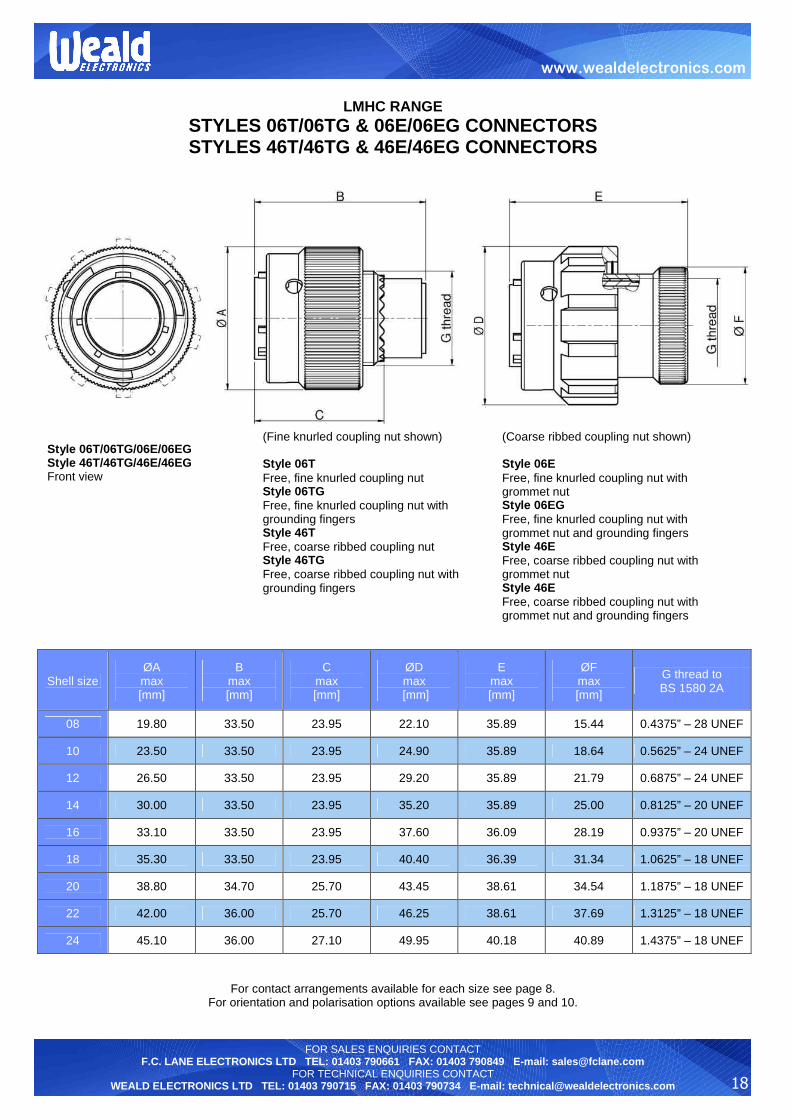
STYLES 06T/06TG & 06E/06EG CONNECTORS STYLES 46T/46TG & 46E/46EG CONNECTORS
For contact arrangements available for each size see page 8. For orientation and polarisation options available see pages 9 and 10.
Shell size ØA max [mm]
B max [mm]
C max [mm]
ØD max
[mm]
E max [mm]
ØF max [mm]
G thread to BS 1580 2A
08 19.80 33.50 23.95 22.10 35.89 15.44 0.4375” – 28 UNEF
10 23.50 33.50 23.95 24.90 35.89 18.64 0.5625” – 24 UNEF
12 26.50 33.50 23.95 29.20 35.89 21.79 0.6875” – 24 UNEF
14 30.00 33.50 23.95 35.20 35.89 25.00 0.8125” – 20 UNEF
16 33.10 33.50 23.95 37.60 36.09 28.19 0.9375” – 20 UNEF
18 35.30 33.50 23.95 40.40 36.39 31.34 1.0625” – 18 UNEF
20 38.80 34.70 25.70 43.45 38.61 34.54 1.1875” – 18 UNEF
22 42.00 36.00 25.70 46.25 38.61 37.69 1.3125” – 18 UNEF
24 45.10 36.00 27.10 49.95 40.18 40.89 1.4375” – 18 UNEF
Style 06T/06TG/06E/06EG Style 46T/46TG/46E/46EG Front view
(Fine knurled coupling nut shown) Style 06T Free, fine knurled coupling nut Style 06TG Free, fine knurled coupling nut with grounding fingers Style 46T Free, coarse ribbed coupling nut Style 46TG Free, coarse ribbed coupling nut with grounding fingers
(Coarse ribbed coupling nut shown) Style 06E Free, fine knurled coupling nut with grommet nut Style 06EG Free, fine knurled coupling nut with grommet nut and grounding fingers Style 46E Free, coarse ribbed coupling nut with grommet nut Style 46E Free, coarse ribbed coupling nut with grommet nut and grounding fingers

19
FOR SALES ENQUIRIES CONTACT F.C. LANE ELECTRONICS LTD TEL: 01403 790661 FAX: 01403 790849 E-mail: [email protected]
FOR TECHNICAL ENQUIRIES CONTACT WEALD ELECTRONICS LTD TEL: 01403 790715 FAX: 01403 790734 E-mail: [email protected]
www.wealdelectronics.com
LMHC RANGE
STYLES 00E & 00F CONNECTORS
For contact arrangements available for each size see page 8.
For orientation and polarisation options available see pages 9 and 10. For panel piercing details see page 31.
Shell size
A max [mm]
ØB max [mm]
C max [mm]
D max
[mm]
ØE + 0.3 - 0.7 [mm]
ØF min
[mm]
G max [mm]
08 40.00 15.44 61.50 21.10 3.20 4.90 5.94
10 40.00 18.64 61.50 22.70 4.80 4.90 7.54
12 40.00 21.79 61.50 25.90 7.90 7.40 10.72
14 40.00 25.00 61.50 29.00 9.50 8.40 13.90
16 40.00 28.19 64.40 30.60 12.70 9.20 15.47
18 40.00 31.34 64.40 37.40 15.90 11.70 18.64
20 44.00 34.54 71.10 37.40 15.90 13.30 18.64
22 44.00 37.69 71.10 42.10 19.10 13.30 23.42
24 44.00 40.89 73.60 44.50 20.30 16.80 25.00
Style 00F (VG Style – B) Fixed, square flange mounting with cable clamp
Style 00E (VG Style – A) Fixed, square flange mounting with grommet nut
20
FOR SALES ENQUIRIES CONTACT F.C. LANE ELECTRONICS LTD TEL: 01403 790661 FAX: 01403 790849 E-mail: [email protected]
FOR TECHNICAL ENQUIRIES CONTACT WEALD ELECTRONICS LTD TEL: 01403 790715 FAX: 01403 790734 E-mail: [email protected]
www.wealdelectronics.com
LMHC RANGE
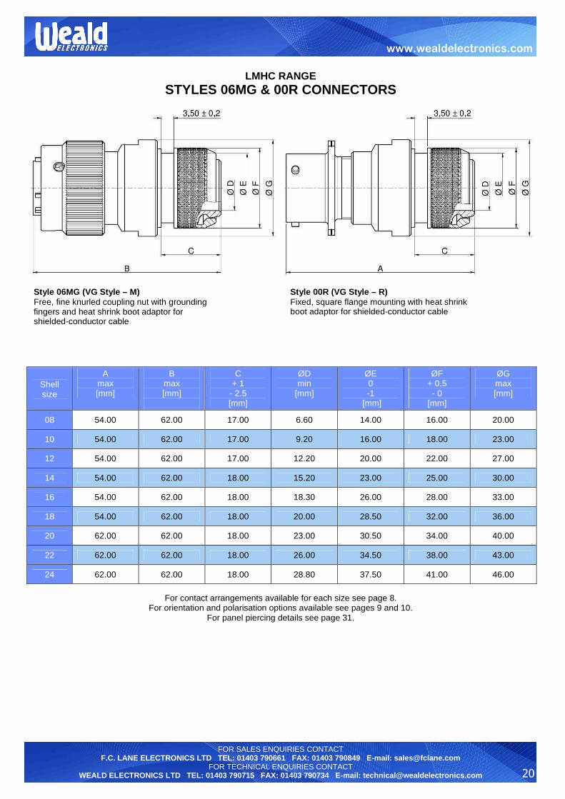
STYLES 06MG & 00R CONNECTORS
For contact arrangements available for each size see page 8.
For orientation and polarisation options available see pages 9 and 10. For panel piercing details see page 31.
Shell size
A max [mm]
B max [mm]
C + 1
- 2.5 [mm]
ØD min
[mm]
ØE 0 -1
[mm]
ØF + 0.5 - 0
[mm]
ØG max [mm]
08 54.00 62.00 17.00 6.60 14.00 16.00 20.00
10 54.00 62.00 17.00 9.20 16.00 18.00 23.00
12 54.00 62.00 17.00 12.20 20.00 22.00 27.00
14 54.00 62.00 18.00 15.20 23.00 25.00 30.00
16 54.00 62.00 18.00 18.30 26.00 28.00 33.00
18 54.00 62.00 18.00 20.00 28.50 32.00 36.00
20 62.00 62.00 18.00 23.00 30.50 34.00 40.00
22 62.00 62.00 18.00 26.00 34.50 38.00 43.00
24 62.00 62.00 18.00 28.80 37.50 41.00 46.00
Style 06MG (VG Style – M) Free, fine knurled coupling nut with grounding fingers and heat shrink boot adaptor for shielded-conductor cable
Style 00R (VG Style – R) Fixed, square flange mounting with heat shrink boot adaptor for shielded-conductor cable
21
FOR SALES ENQUIRIES CONTACT F.C. LANE ELECTRONICS LTD TEL: 01403 790661 FAX: 01403 790849 E-mail: [email protected]
FOR TECHNICAL ENQUIRIES CONTACT WEALD ELECTRONICS LTD TEL: 01403 790715 FAX: 01403 790734 E-mail: [email protected]
www.wealdelectronics.com
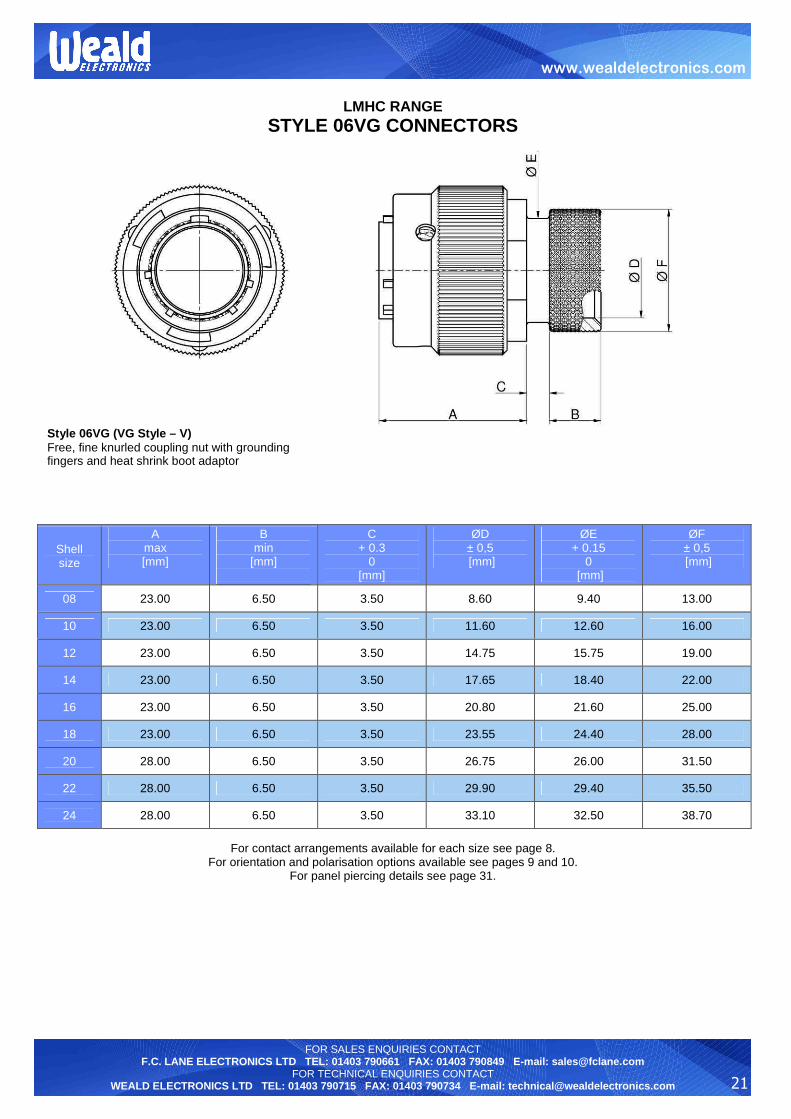
LMHC RANGE
STYLE 06VG CONNECTORS
For contact arrangements available for each size see page 8.
For orientation and polarisation options available see pages 9 and 10. For panel piercing details see page 31.
Shell size
A max [mm]
B min
[mm]
C + 0.3
0 [mm]
ØD ± 0,5 [mm]
ØE + 0.15
0 [mm]
ØF ± 0,5 [mm]
08 23.00 6.50 3.50 8.60 9.40 13.00
10 23.00 6.50 3.50 11.60 12.60 16.00
12 23.00 6.50 3.50 14.75 15.75 19.00
14 23.00 6.50 3.50 17.65 18.40 22.00
16 23.00 6.50 3.50 20.80 21.60 25.00
18 23.00 6.50 3.50 23.55 24.40 28.00
20 28.00 6.50 3.50 26.75 26.00 31.50
22 28.00 6.50 3.50 29.90 29.40 35.50
24 28.00 6.50 3.50 33.10 32.50 38.70
Style 06VG (VG Style – V) Free, fine knurled coupling nut with grounding fingers and heat shrink boot adaptor

22
FOR SALES ENQUIRIES CONTACT F.C. LANE ELECTRONICS LTD TEL: 01403 790661 FAX: 01403 790849 E-mail: [email protected]
FOR TECHNICAL ENQUIRIES CONTACT WEALD ELECTRONICS LTD TEL: 01403 790715 FAX: 01403 790734 E-mail: [email protected]
www.wealdelectronics.com
LMHC RANGE
STYLE 06F/06FG CONNECTORS STYLE 46F/46FG CONNECTORS
For contact arrangements available for each size see page 8. For orientation and polarisation options available see pages 9 and 10.
Shell size
A max [mm]
ØB max [mm]
C max [mm]
ØD + 0.3 - 0.7 [mm]
ØE min
[mm]
ØF max [mm]
08 61.30 15.44 21.10 3.20 4.90 5.94
10 61.30 18.64 22.70 4.80 4.90 7.54
12 61.30 21.79 25.90 7.90 7.40 10.72
14 61.30 25.00 29.00 9.50 8.40 13.90
16 64.30 28.19 30.60 12.70 9.20 15.47
18 64.30 31.34 37.40 15.90 11.70 18.64
20 70,00 34.54 37.40 15.90 13.30 18.64
22 70,00 37.69 42.10 19.10 13.30 23.42
24 71.90 40.89 44.50 20.30 16.80 25.00
Style 06F (VG Style – K) Free, fine knurled coupling nut with cable clamp Style 06FG Free, fine knurled coupling nut with cable clamp and grounding fingers
Style 46F Free, coarse ribbed coupling nut with cable clamp Style 46FG Free, coarse ribbed coupling nut with cable clamp and grounding fingers
23
FOR SALES ENQUIRIES CONTACT F.C. LANE ELECTRONICS LTD TEL: 01403 790661 FAX: 01403 790849 E-mail: [email protected]
FOR TECHNICAL ENQUIRIES CONTACT WEALD ELECTRONICS LTD TEL: 01403 790715 FAX: 01403 790734 E-mail: [email protected]
www.wealdelectronics.com
LMHC RANGE
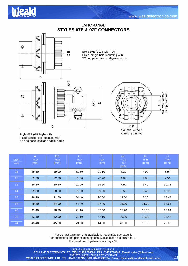
STYLES 07E & 07F CONNECTORS
For contact arrangements available for each size see page 8. For orientation and polarisation options available see pages 9 and 10.
For panel piercing details see page 31.
Shell size
A max [mm]
ØB max [mm]
C max [mm]
D max
[mm]
ØE + 0.3 - 0.7 [mm]
ØF min
[mm]
G max [mm]
08 39.30 19.00 61.50 21.10 3.20 4.90 5.94
10 39.30 22.20 61.50 22.70 4.80 4.90 7.54
12 39.30 25.40 61.50 25.90 7.90 7.40 10.72
14 39.30 28.50 61.50 29.00 9.50 8.40 13.90
16 39.30 31.70 64.40 30.60 12.70 9.20 15.47
18 39.30 34.90 64.40 37.40 15.90 11.70 18.64
20 43.40 38.80 71.10 37.40 15.90 13.30 18.64
22 43.40 42.00 71.10 42.10 19.10 13.30 23.42
24 43.40 45.20 73.60 44.50 20.30 16.80 25.00
Style 07F (VG Style – E) Fixed, single hole mounting with ‘O’ ring panel seal and cable clamp
Style 07 E (VG Style – D) Fixed, single hole mounting with ‘O’ ring panel seal and grommet nut
24
FOR SALES ENQUIRIES CONTACT F.C. LANE ELECTRONICS LTD TEL: 01403 790661 FAX: 01403 790849 E-mail: [email protected]
FOR TECHNICAL ENQUIRIES CONTACT WEALD ELECTRONICS LTD TEL: 01403 790715 FAX: 01403 790734 E-mail: [email protected]
www.wealdelectronics.com
LMHC RANGE
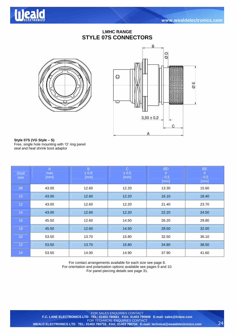
STYLE 07S CONNECTORS
For contact arrangements available for each size see page 8.
For orientation and polarisation options available see pages 9 and 10. For panel piercing details see page 31.
Shell size
A max [mm]
B ± 0,8 [mm]
C ± 0,5 [mm]
ØD 0
- 0.5 [mm]
ØE 0
- 0.5 [mm]
08 43.00 12.60 12.20 13.30 15.60
10 43.00 12.60 12.20 16.10 18.40
12 43.00 12.60 12.20 21.40 23.70
14 43.00 12.60 12.20 22.20 24.50
16 45.50 12.60 14.50 26.20 29.80
18 45.50 12.60 14.50 28.50 32.00
20 53.50 13.70 15.80 32.50 36.10
22 53.50 13.70 15.80 34.80 38.50
24 53.50 14.00 14.90 37.90 41.60
Style 07S (VG Style – S) Free, single hole mounting with ‘O’ ring panel seal and heat shrink boot adaptor
25
FOR SALES ENQUIRIES CONTACT F.C. LANE ELECTRONICS LTD TEL: 01403 790661 FAX: 01403 790849 E-mail: [email protected]
FOR TECHNICAL ENQUIRIES CONTACT WEALD ELECTRONICS LTD TEL: 01403 790715 FAX: 01403 790734 E-mail: [email protected]
www.wealdelectronics.com
LMHC RANGE
ACCESSORIES
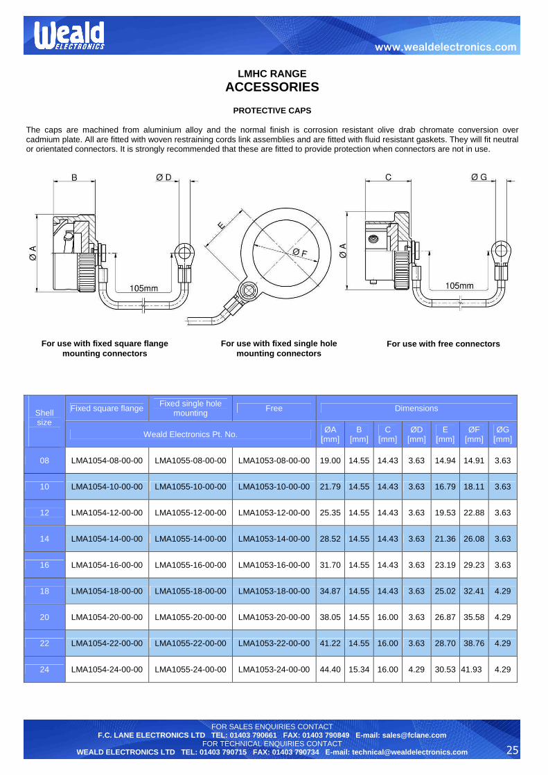
PROTECTIVE CAPS
The caps are machined from aluminium alloy and the normal finish is corrosion resistant olive drab chromate conversion over cadmium plate. All are fitted with woven restraining cords link assemblies and are fitted with fluid resistant gaskets. They will fit neutral or orientated connectors. It is strongly recommended that these are fitted to provide protection when connectors are not in use.
Fixed square flange Fixed single hole mounting Free Dimensions
Shell size
Weald Electronics Pt. No. ØA [mm]
B [mm]
C [mm]
ØD [mm]
E [mm]
ØF [mm]
ØG [mm]
08 LMA1054-08-00-00 LMA1055-08-00-00 LMA1053-08-00-00 19.00 14.55 14.43 3.63 14.94 14.91 3.63
10 LMA1054-10-00-00 LMA1055-10-00-00 LMA1053-10-00-00 21.79 14.55 14.43 3.63 16.79 18.11 3.63
12 LMA1054-12-00-00 LMA1055-12-00-00 LMA1053-12-00-00 25.35 14.55 14.43 3.63 19.53 22.88 3.63
14 LMA1054-14-00-00 LMA1055-14-00-00 LMA1053-14-00-00 28.52 14.55 14.43 3.63 21.36 26.08 3.63
16 LMA1054-16-00-00 LMA1055-16-00-00 LMA1053-16-00-00 31.70 14.55 14.43 3.63 23.19 29.23 3.63
18 LMA1054-18-00-00 LMA1055-18-00-00 LMA1053-18-00-00 34.87 14.55 14.43 3.63 25.02 32.41 4.29
20 LMA1054-20-00-00 LMA1055-20-00-00 LMA1053-20-00-00 38.05 14.55 16.00 3.63 26.87 35.58 4.29
22 LMA1054-22-00-00 LMA1055-22-00-00 LMA1053-22-00-00 41.22 14.55 16.00 3.63 28.70 38.76 4.29
24 LMA1054-24-00-00 LMA1055-24-00-00 LMA1053-24-00-00 44.40 15.34 16.00 4.29 30.53 41.93 4.29
For use with fixed square flange mounting connectors
For use with fixed single hole mounting connectors
For use with free connectors

26
FOR SALES ENQUIRIES CONTACT F.C. LANE ELECTRONICS LTD TEL: 01403 790661 FAX: 01403 790849 E-mail: [email protected]
FOR TECHNICAL ENQUIRIES CONTACT WEALD ELECTRONICS LTD TEL: 01403 790715 FAX: 01403 790734 E-mail: [email protected]
www.wealdelectronics.com
LMHC RANGE CONTACTS
Connectors LMHC use crimp contacts illustrated below. Insert the contacts into contact holes at the rear of the assembly. They are kept in by a dielectric disk provided with individual retention. The contacts can be removed from mating face of connectors with appropriate tools. (see page 29)
Contact Part Numbers
Contact type and size Weald Electronics VG MS
Pin contact size 20 WE2005-00-20-01 VG 95328 P 20 C M39029/31-240
Socket contact size 20 WE2011-00-20-01 VG 95328 S 20 C M39029/32-259
Pin contact size 16 WE2033-00-16-01 VG 95328 P 16 M39029/31-228
Socket contact size 16 WE2036-00-16-01 VG 95328 S 16 M39029/32-247
SEALING PLUGS
Sealing Plug Part Numbers Colour
Contact Size Weald
Electronics MS
20 WE2032-00-20-00 MS27488-20 red
16 WE2032-00-16-00 MS27488-16 blue
27
FOR SALES ENQUIRIES CONTACT F.C. LANE ELECTRONICS LTD TEL: 01403 790661 FAX: 01403 790849 E-mail: [email protected]
FOR TECHNICAL ENQUIRIES CONTACT WEALD ELECTRONICS LTD TEL: 01403 790715 FAX: 01403 790734 E-mail: [email protected]
www.wealdelectronics.com
LMHC RANGE
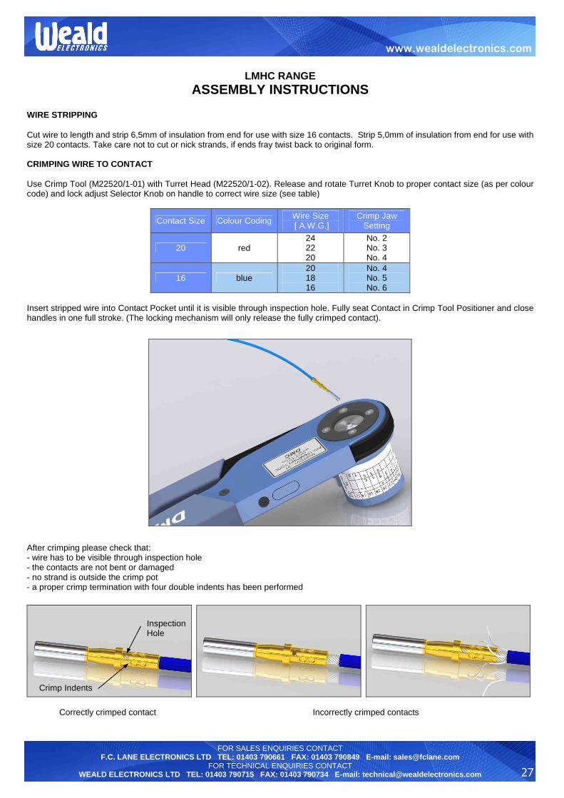
ASSEMBLY INSTRUCTIONS
WIRE STRIPPING Cut wire to length and strip 6,5mm of insulation from end for use with size 16 contacts. Strip 5,0mm of insulation from end for use with size 20 contacts. Take care not to cut or nick strands, if ends fray twist back to original form. CRIMPING WIRE TO CONTACT Use Crimp Tool (M22520/1-01) with Turret Head (M22520/1-02). Release and rotate Turret Knob to proper contact size (as per colour code) and lock adjust Selector Knob on handle to correct wire size (see table)
Contact Size Colour Coding Wire Size [ A.W.G.]
Crimp Jaw Setting
20 red 24 22 20
No. 2 No. 3 No. 4
16 blue 20 18 16
No. 4 No. 5 No. 6
Insert stripped wire into Contact Pocket until it is visible through inspection hole. Fully seat Contact in Crimp Tool Positioner and close handles in one full stroke. (The locking mechanism will only release the fully crimped contact).
After crimping please check that: - wire has to be visible through inspection hole - the contacts are not bent or damaged - no strand is outside the crimp pot - a proper crimp termination with four double indents has been performed
Correctly crimped contact Incorrectly crimped contacts
Inspection Hole
Crimp Indents

28
FOR SALES ENQUIRIES CONTACT F.C. LANE ELECTRONICS LTD TEL: 01403 790661 FAX: 01403 790849 E-mail: [email protected]
FOR TECHNICAL ENQUIRIES CONTACT WEALD ELECTRONICS LTD TEL: 01403 790715 FAX: 01403 790734 E-mail: [email protected]
www.wealdelectronics.com
LMHC RANGE
ASSEMBLY INSTRUCTIONS CONTACT INSERTION Select the proper insertion tool for the size of contact (see table). Slide rear accessory (if applicable) over wire bundle. Lay wire in groove of insertion tool and the tool tip butts against the contact shoulder.
Insert contact into the correct hole in the rear face of grommet. The insertion tool has to be in axial position to the insulator face area to prevent damage to contacts. Insert contact slowly into connector until it snaps in audibly. Withdraw tool at right angles to grommet surface until completely free of connector. Slightly pull cable and check the correct position of contact. Contacts must be inserted whether in circuit or not and the appropriate size sealing plug used behind any contacts that are not wired. Push the sealing plug in by hand until it is fully seated.
Insertion tool can damage insulator, contact or contact clip when it is not used according to instructions, when twisted or is itself damaged. If any part is damaged it must be replaced. After insertion of contacts, check connector on the mating side to ensure all contacts are at the same level.
Contact Size Insertion Tool No.
20 MS 24256A20
16 MS 24256A16
Contact shoulder
Tool

29
FOR SALES ENQUIRIES CONTACT F.C. LANE ELECTRONICS LTD TEL: 01403 790661 FAX: 01403 790849 E-mail: [email protected]
FOR TECHNICAL ENQUIRIES CONTACT WEALD ELECTRONICS LTD TEL: 01403 790715 FAX: 01403 790734 E-mail: [email protected]
www.wealdelectronics.com
LMHC RANGE
ASSEMBLY INSTRUCTIONS CONTACT REMOVAL Remove the rear accessory (if applicable) and slide back on wire bundle. Select the proper removal tool for size of contact from table. Position the removing tool over the contacts to be removed and push until tool probe is fully bottomed. Slide the plunger forward to remove contact.
Contact Size Insertion Tool No.
20 MS 24256R20
16 MS 24256R16

30
FOR SALES ENQUIRIES CONTACT F.C. LANE ELECTRONICS LTD TEL: 01403 790661 FAX: 01403 790849 E-mail: [email protected]
FOR TECHNICAL ENQUIRIES CONTACT WEALD ELECTRONICS LTD TEL: 01403 790715 FAX: 01403 790734 E-mail: [email protected]
www.wealdelectronics.com
LMHC RANGE
ASSEMBLY INSTRUCTIONS
FIXING OF SHIELDED-CONDUCTOR CABLE TO CONNECTORS WITH HEA T SHRINK BOOT ADAPTOR
- Unscrew the outlet nut (3) - Slide the thermoshrinkable tube (6) and the outlet nut (3) over the cable (8) - Insert the shielding braid (7) onto the outlet adaptor (5) and over the thread (2) - Fix the shielding braid (7) with iron-wire (4) into the undercut - Fold back the protruding shielding braid on cone - Slide the outlet nut (3) onto the outlet adaptor (5). The folded back shielding braid protrudes under the tightened outlet nut. - Shrink the thermoshrinkable tube (6) by inserting end of tube into the undercut (1)

31
FOR SALES ENQUIRIES CONTACT F.C. LANE ELECTRONICS LTD TEL: 01403 790661 FAX: 01403 790849 E-mail: [email protected]
FOR TECHNICAL ENQUIRIES CONTACT WEALD ELECTRONICS LTD TEL: 01403 790715 FAX: 01403 790734 E-mail: [email protected]
www.wealdelectronics.com
LMHC RANGE
ASSEMBLY INSTRUCTIONS
PANEL PIERCING DATA
PANEL PIERCING DIMENSIONS
ØB + 0,25
0 [mm]
Shell size
A ± 0,15 [mm]
for back mounting
for front mounting
ØC + 0,25
0 [mm]
D + 0,12
- 0 [mm]
08 15.1 14.0 12.7 14.5 13.6
10 18.3 17.0 16.0 17.7 16.8
12 20.6 22.0 19.0 22.7 20.9
14 23.0 25.0 22.2 25.7 24.1
16 24.6 28.0 25.5 28.8 27.2
18 27.0 31.0 28.5 32.0 30.4
20 29.4 34.5 31.7 35.1 33.6
22 31.8 37.5 35.0 38.4 36.8
24 34.9 41.0 38.0 41.5 40.0
For all fixed square flange shell styles
For all fixed single hole mounting shell styles
Max. panel thickness: Front mounting: 9,5mm Rear mounting: 2,21mm – sizes 8-18 5,38mm – sizes 20-24 Fixing bolts are required when mounting. These are NOT supplied with the connector.
Shell styles 07A and 07T are designed for rear panel mounting only. When mounted in the correct manner a pressure proof seal is achieved at the panel face. Min. panel thickness: 1,5mm Max. panel thickness: 3,3mm - shell sizes 08-18 6,4mm – shell sizes 20-24 (including protective cap washer when used)
32
FOR SALES ENQUIRIES CONTACT F.C. LANE ELECTRONICS LTD TEL: 01403 790661 FAX: 01403 790849 E-mail: [email protected]
FOR TECHNICAL ENQUIRIES CONTACT WEALD ELECTRONICS LTD TEL: 01403 790715 FAX: 01403 790734 E-mail: [email protected]
www.wealdelectronics.com
LMHC RANGE
PRODUCT SAFETY INFORMATION
These notes are intended to be used in conjunction with the Product Catalogue and Product Specification. Products may be safely used in the applications for which they have been designed and within the specified rating and environments. If products are exposed to condition outside the performance ratings or specified environments they may constitute a hazard. In particular it should be noted that:-
1. Material Content Circular Connectors generally use metalwork parts made of brass, aluminium, phosphor-bronze or steel, which, dependant on the particular application, may be passivated and protect with cadmium or zinc plate – in conjunction with chromated or anodised surface finishes. The insulating materials can either be natural or synthetic rubber, together with plastic or glass-filled plastic moulded parts. Contact materials vary but are usually made of brass, phosphor-bronze, alumel or chromel. 2. Electric Shock, Burns and Fire Hazard can occur if the product is used outside the specified parameters or if the product is damaged, wrongly wired or poorly assembled, or poorly integrated into larger equipments, or contaminated with conductive fluids. Live circuit terminations must be protected and live circuits never broken by disconnecting products. Hot spots may be created when resistance is increased due to damage or incorrect integration particularly soldering, or loose terminations. Overheating can cause breakdown of insulation, electric shock, burns or, ultimately, fire. In the event of fire noxious and/or toxic fumes may be released and, in these circumstances, any fire involving the product should be dealt with by personnel properly equipped. Connectors with exposed terminations or contacts should not be used on the current supply side of a circuit with exposed contacts on an unmated product. Before making a circuit live, the product and wiring should be checked to ensure there is no electrically conducting debris present. Circuit resistance checks should also be conducted before making the circuit live. Always ensure that connectors are assembled and wired by properly trained personnel. 3. Use, Transport and Storage of Products Care must be exercised to avoid damage to any part of the products during transporting, storage or use. Abnormal transit or storage conditions and abuse during installation can give rise to damage. Products should not be used in a damage condition. Improper storage (particularly of damaged products) can give rise to additional hazards particularly corrosion. Your attention is specifically drawn to the need for proper storage of products containing cadmium and you are advised to see the Guidance Note from the Health and safety Executive on Cadmium – Health and Safety Precautions. 4. Disposal of Products Product should not be burnt.
SAFETY RULES 1. FOLLOW THE GUIDELINES GIVEN. 2. ALWAYS PROTECT LIVE CIRCUITS AND NEVER DISCONNECTOR A LIVE CONNECTOR 3. NEVER USE A DAMAGED CONNECTOR. 4. NEVER BURN DISCARGED CONNECTORS.