lmc's application and supporting documentation submitted to the american bureau of shipping
TRANSCRIPT

Application to: American Bureau of Shipping
Submitted to US EPA by: Lake Michigan Carferry Service Dated: March 13, 2014
All CONFIDENTIAl BUSINESS INFORMATION
REDACTED BY lAKE MICHIGAN CARFERRY SERVICE

THIS PAGE
INTENTIONALLY LEFT BLANK

From: Sent: Friday, March 07, 20141:10 PM To: Marine Shop Subject: FW: SS Badger Boiler Combustion Control Submittals 1 of 2
Chuck
This is our ABS submittal information 1 of 2 emails sent. I will also send you the second half next. Use this for your installation drawings . We have made some changes in Power Distribution drawings . • From: Sent: To: [email protected]; [email protected] Subject: FW: SS Badger Boiler Combustion Control Submittals
1
CONTAINS CONFIDENTIAL BUSINESS INFORMATION

Dear Henry & Mohammad,
I am sending this Submittal in two or more em ails because of the size.
Please find the above SS Badger Boiler Combustion Control project submittals attachments for your review. Our cover letter is attached giving an overview of the project and a list of Enclosures for your review. The installation of the new systems is now being performed aboard the SS Badger in ludington, Michigan during the vessels winter lay-up. The project is to be completed in April to begin testing, dock trials and sea trials to be ready for the first voyage on May 161
h. In other words we need to have this review treated as urgent. We had the Hindle Power Inc. 24 VDC power supply system that we are using for redundant power to our systems reviewed and factory tested and approved by ABS in January. ABS Project No. 3176956, Task No. 1134456. Chuck Cart the SS Badger's Senior Chief Engineer has had the local USCG and ABS office involved in the project. We will send you a formal purchase order today. The PO number will be BAD030714. Please feel free to give me a call or email me with any questions.
Respectfully
•
2
CONTAINS CONFIDENTIAL BUSINESS INFORMATION

March 6, 2014
Mr. Henry Robles, Principal Engineer American Bureau of Shipping Ship Systems Group Engineering Services Department 16855 Northchase Drive Houston, Texas 77060-6008
Subject: Submittal of Plans in Agreement with Navigation and Vessel Inspection Circular (NVIC) 10-92, for SS Badger, ABSID 5300348, IMO 5033583, Hull370.
Dear Mr. Robles:
This plan submittal is for the upgrading of the SS Badger's manually-operated coalburning boiler systems to Automatic Combustion Control, supervised operation. Boiler light-off, shutdown and day-to-day operation will continue as a fully-supervised, operator attended, manual system only. The Automatic Combustion Control systems are intended to provide improved efficiency, economy and emissions. Safety supervision of all lighting, shutdown and ash dumping will continue to be strictly a manual operation.
This plan submittal is NOT for reclassification of vessel's marming. The engine room/boiler room will be manned by a full complement of crew member and engineering officers.
Since it is the intent that this plan submittal be performed in agreement with Navigation and V essellnspection Circular (NVIC) I 0-92, please review the attached plans and forward approved submittals to the USCG per (NVIC) 10-92, as well as, the USCG Sector Lake Michigan, Milwaukee, WI an~ office in Sturgeon Bay, WI. Please retum at least one stamped copy to-.
CONTAINS CONFIDENTIAL BUSINESS INFORMATION

This plan submittal is for the installation of the following systems:
I. Automatic Combustion Control- Each Boiler 2. Drum Level- Each Boiler (To be addressed separately in 2015) 3. Feed pump control (To be addressed separately in 2015) 4. Redundant 24VDC Power Supply systems 5. Consoles and cabinets for Port and Starboard boiler 6. Feedwater Control Panel for Engine Room
System Descriptions
All of the following systems' control and computing functions are performed by Siemens, ABS Type-Approved, Model353 Loop Controllers. The Operator monitoring and interface stations (HMI) employ ABS Type-Approved PCs. Refer to the systems' I/0 Data Sheets for all systems' l/0 types and channel addresses. The l/0 Data Sheets list the channels for each controller. The 353 systems hardware and software used in this project have been used and previously approved by ABS & USCG for ACC systems aboard the AAA class ship Steamers Philip R. Clarke, Arthur M. Anderson, LNG/C Matthew, SS Wright & SS Curtiss.
1. Boiler Automatic Combustion Control Automatic Combustion Control system consists of Siemens 353 controllers and will be of the GRB, fully-metered and cross-limited design. This design has proven to be stable, repeatable and flexible, and is highly efficient in fuel savings.
2. Boiler Drum-Level, 2-Element (to be integrated in 2015) Drum level systems are of the GRB design, utilizing steam flow to characterize the feed water valve position and drum level to trim the results. This system has been proven to be the most accurate and stable of all loop configurations for drum-level control. Two drum level transmitters per boiler, using separate taps, are provided. One transmitter provides level control and High/Low alarm functions. The other drum level transmitter provides separate level indication, Low-Low Drum Level, Coal Feeder trips and alarms. All drum level control computations and l/0 are incorporated in Siemens 353 controllers.
4. Systems Power Supply All DC systems' power requirements will be supplied by redundant, 24 VDC, Marine Duty, Charging Units, as previously utilized and approved aboard the Steamer Philip R. Clarke, Arthur M. Anderson, Cason J. Callaway, and LNG/C Matthew. These units will also provide power for the 24VDC requirements ofthe, two HMI, ABS Type-Approved Flat-Panel PCs. AC power feeding the 24 VDC systems will come from two feeders; one from the main and one from the emergency switchboard. This configuration is per ABS 4-9-3/3.5.1 "System power supply".
5. Cabinets & Enclosures Dedicated and vortex-cooled enclosures will house the two ABS type-approved, Flat Panel, Touchscreen PCs. The engine-room, Feed Panel enclosure, will house the Feedpump 353 controllers (future) and four Dixson Drum Level meters. In addition, there will be one Dixson, D.A. Level meter to be added in the future. The Dixson level indicators have been successfully used aboard the Cason J. Callaway, Arthur M. Anderson, Philip R. Clarke, John G. Munson and many other ABS vessels.
6. Supervisory Only
The ABS Coal Burning Document: Publication 2 I and portions ofNFPA 86 were used as guides wherever described elements were considered appropriate to this application. Such elements as practicable have been incorporated in the design to provide such supervisory protections as water-level.alarms, low-low water trips of coal feeders, high steam and furnace pressure alanns and coal feeder/rotor interlocks. Please refer to the accompanying, ABS Guide for Ships Buming Coal- Annotations document for additional clarification.
Please note: all submittals are in electronic format, comprised of zipped folders, containing MS Word and Excel formatted files or pdf documents.
Respectfully Submitted,
Enclosures:
Boiler Panels' Wiring and Cable Identification Schedule
Analog Transmitter list with cable assigrunents
Annotated Excerpt from ABS Coal Burning Ships Document- Publication 21
Self-Certification Letter, -3 Pages
ABS/Marine Agencies' Type-Approvals with Listings
Siemens Model353 Controller Logic Drawings- 27 Controllers
System Wiring Drawings:
Port and Starboard Boiler Control Cabinets
CONTAINS CONFIDENTIAL BUSINESS INFORMATION

Feedwater Control/Monitoring Panel
Siemens Motor Supervisory PLC system T/0
Siemens Model 353 Controllers' Wiring
Copy ofletter from USCG Sector Lake Michigan

LIST OF CERTIFICATIONS
1. Siemens 353 Loop Controllers- ABS 02-2HS68273-3-PDA.pdf 2. Danfoss Variable Frequency Drives- ABS TAC 06-LD192435-2-PDA (OK). pdf 3. Vortex Airflow Metering- ABS Type Cert 8800 Vortex. pdf 4. Hindle Power Test Instructions- CD5008-00_80349323.pdf 5. HindlePower Specification- JF5036-00_80350026.pdf 6. HindlePower ABS Letter- T1134456, letter_80349328.pdf 7. SITRANS P DSIII Transmitters- 03-HS360494-2-PDA.pdf 8. S7300 PLC- 01-HG189457-5-PDA.pdf 9. Hatteland PC Approvals- 12-LD908273-1-PDA.pdf 10. Hirschmann Ethernet Switches- 3288006.pdf (Germanischer Lloyd) 11. Belden Cat 5e Cables- 1300SB

Certificate Number: 02-HS268273-3-PDA 08/AUG/2013
Confirmation of Product Type Approval Please refer to the "Service Restrictions" shown below to determine if Unit Certification is required for this product.
This certificate reflects the information on the product in the ASS Records as of the date and time the certificate is printed.
Pursuant to the Rules of the American Bureau of Shipping (ABS), the manufacturer of the below listed product held a valid Manufacturing Assessment (MA) with expiration date of 26/FES/2018. The continued validity of the Manufacturing Assessment is dependent on completion of satisfactory audits as required by the ASS Rules.
And; a Product Design Assessment (PDA) valid until 04/FEB/2018 subject to continued compliance with the Rules or standards used in the evaluation of the product.
The above entitle the product to be called Product Type Approved.
The Product Design Assessment is valid for products intended for use on ASS classed vessels, MODUs or facilities which are in existence or under contract for construction on the date of the ASS Rules used to evaluate the Product.
ABS makes no representations regarding Type Approval of the Product for use on vessels, MODUs or facilities built after the date of the ABS Rules used for this evaluation.
Due to wide variety of specifications used in the products ASS has evaluated for Type Approval, it is part of our contract that; whether the standard is an ABS Rule or a non-ABS Rule, the Client has full responsibility for continued compliance with the standard.
Product Name: Process Automation Controller Model Name(s): TGX:353
Presented to: SIEMENS INDUSTRY, INC. 1201 SUMNEYTOWN PIKE P.O. BOX 900 SPRING HOUSE United States
Intended Service:
Description:
Ratings:
Service Restrictions:
Marine & Offshore Application - Capable of Measuring, Controlling, and/or Communicating Thermocouples, RTD's Voltage, Current, Relay I/O's etc. - Flow, Level, Pressure, etc. -On Board ACC, ACCU, and ABCU Classed Vessels
Universal Microprocessor Based Multi Purpose Panel Mounted Loop Process Automation Controller.(See User's Manual UM353-I for options).
Input Power: 120/240 V AC, 47-63Hz, 40 VA or 24 V DC, 25 W; Outputs: Analog - 4/20/mA, Digital 0 - 30 V DC, 100 rnA, Transmitter Power 28 V DC, 120 mA, Relay Contacts 5 A@ 120 V AC or 2.5 A@ 240 V AC; Inputs: Analog 0-5 V DC, Digital30 V DC Maximum; Maximum Ambient Temperature: 60 °C; Temperature Code: T3C (160 °C) DC Models; T4A (120 °C) AC Models; Non-lncendive for use in Class 1, Division 2, Groups A, B, C and D Hazardous Indoor locations. Only approved options as per Clause 1.2 of FM Approval Report FMRC J.I.3B4A4.AX (3611 }, dated January 8, 1997 are being utilized;
Unit Certification is not required for this product. If the manufacture~ or purchaser's request an ABS Certificate for compliance with a specification or standard; the- ., specification or standard, incLuding inspection standards and tolerances, must be clearly defined. 1) The integrity of the Automatic or Remote Control and Monitoring Systems utilizing the Model TGX:353, Universal Loop Controller is to be verified by ln~ahs of a Failu~e Mode and Effect Analysis on the basis of a Single Failure Mode.

Comments:
Notes I Documentation:
Term of Validity:
ABS Rules:
National Standards: International Standards:
Government Authority: EUMED: Others:
Model Certificate
PDA
Certificate Number: 02-HS268273-3-PDA
Criteria; 2) Model TGX:353 Universal Loop Controller is to be installed in accordance with FM Controlled Document Drawings, certifying Laboratory (FM and CSA- see Standards) Reports and Certificates and Manufacturer's Specifications; 3) This approval covers Hardware only. Each Ship-specific application must be approved on a case-by-case basis. 4) Emissions within limits for Bridge and Deck Zone except at 159.99 MHZ. To comply the Unit must be used in an Enclosure that provides at least 24dB §V of Attenuation at this Frequency.
The Manufacturer has provided a declaration about the control of, or the lack of Asbestos in this product.
Supporting Data: CSA (Certificate of Compliance No. LR 38024-121, Dated Dec. 19, 1996), FM (FM Approval Report No. FMRC J.I3B4A4.AX (3611), Dated Jan. 8, 1997 & FMRC J.l. 384A4.AX dated 14 December 2001& Revision Report dated 30 Oct 2003 & 12 July 2005 • Dwg No. 16376-19A,Rev.4, Overviey.' Schematic 353E MPU,10 Shts; * Dwg No. 16353-34,Rev.8, Bezel & Keyboard Assy 353,4 Shts; * Dwg No. 16376-20,Rev.3, Assy Dwg 353E MPU; • Dwg No. 16353-36,Rev.4, Term Cover 353 Rear Plate; • Dwg No. 16353-6,Rev.2, Flange-Die Casting ; • Dwg No. 15232-114,Rev.3, PCB SMOBC, GL 353E MPU * Dwg No. 16281-99A,Rev.3, Schematic 353 LED Display;* Dwg No. 16297-20,Rev.5, Assy Dwg 353E LIL; * Dwg No. 16353-21 ,Rev.3, Machining/Assy Dwg 353E Case; • Dwg No. 16344-20,Rev.2, Assy Dwg 353E Ethernet; • Dwg No. 16298-90,Rev.2, Assy Dwg 353E Lonworks;
This Product Design Assessment (PDA) Certificate 02-H$268273-3-PDA, dated 05/Feb/2013 remains valid until 04/Feb/2018 or until the Rules or specifications used in the assessment are revised (whichever occurs first). This PDA Is intended for a product to be installed on an ABS classed vessel, MODU or facility which is in existence or under contract for construction on the date of the ABS Rules or specifications used to evaluate the Product. Use of the Product on an ABS classed vessel, MODU or facility which is contracted after the validity date of the ABS Rules and specifications used to evaluate the Product, will require re-evaluation of the PDA. Use of the Product for non ABS classed vessels, MODUs or facilities is to be to an agreement between the manufacturer and intended client.
2013 Steel Vessels Rules 1-1-4/7.7, 1-1-A3, 4-9-7113;
EN61010-1, 2nd Ed
Model Certificate No Issue Date Expiry Date
02-HS268273-3-PDA 05/FEB/2013 04/FEB/2018
ABS Programs ABS has used due diligence Jn the preparation of this certificate and it represents the information on the product in the ABS Records as of the date and time the certificate was printed. Type Approval requires Drawing Assessment, Prototype Testing and assessment of the manufacturer's qualify assurance and quality control arrangements. Umited circumstances may allow only Prototype Testing to satisfy Type Approval. The approvals of Drawings and Products remain valid as long as the ABS Rule, to which they were assessed, relllains valid. ABS cautions manufacturers to rEivlew and maintain compliance with all other sj:ieclficatlons to which the proc!uct may have been assessed. Fl,lrther, unless lt is specifically ii'ldicated in the description of the product; Type Approval does not necessarily waive witnessed inspection or survey procedures (where otherwise required) for products to be used in a vessel, MODU or facility intended to be ASS classed or that is presently in class with ABS. Questions regarding the validity of ABS Rules or the need for supplemental testing or inspection of such products should. in all cases. be addressed to ABS.

Certificate Number: 06-LD192435/2-PDA 24/0CT/2013
Confirmation of Product Type Approval Please refer to the "Service Restrictions" shown below to determine if Unit Certification is required for this product.
This certificate reflects the information on the product in the ABS Records as of the date and time the certificate is printed.
Pursuant to the Rules of the American Bureau of Shipping (ABS), the manufacturer of the below listed product held a valid Manufacturing Assessment (MA) with expiration date of 05/0CT/2016. The continued validity of the Manufacturing Assessment is dependent on completion of satisfactory audits as required by the ABS Rules.
And; a Product Design Assessment (PDA) valid until 05/MAY/2014 subject to continued compliance with the Rules or standards used in the evaluation of the product.
The above entitle the product to be called Product Type Approved.
The Product Design Assessment is valid for products intended for use on ABS classed vessels, MODUs or facilities which are in existence or under contract for construction on the date of the ABS Rules used to evaluate the Product.
ABS makes no representations regarding Type Approval of the Product for use on vessels, MODUs or facilities built after the date of the ABS Rules used for this evaluation.
Due to wide variety of specifications used in the products ABS has evaluated for Type Approval, it is part of our contract that; whether the standard is an ABS Rule or a non-ABS Rule, the Client has full responsibility for continued compliance with the standard.
Product Name: Frequency Converter Model Name(s): VLT® Automation Drive FC300 series type FC301/302, VLT®
AQUA Drive series FC202 and VL T® HVAC Drive series FC1 02 Presented to: DANFOSS POVVER ELECTRONICS A/S ULSNAES 1 DK-6300 GRMSTEN Denmark
Intended Service:
Description:
Ratings:
Service Restrictions:
Comments:
Notes I Documentation:
10/24/2013 4:25:52 PJv1
Marine and Offshore Installations.
FC 102, FC202 and FC30x series configurations are as per attached product description.
Whole range of ratings is per the configurations in attached product description sheet.
Unit Certification is required for drive units where required for essential services as per 4-8-3/5.11 and 4-8-5/5.17.9 of the Rules.
1) Tests and approval are for the basic components. Each configuration and external connection is to be specifically approved. 2) Main propulsion control systems are assigned with System Category II in accordance with 4-9-6/Table 2 of the SVR. If the subject drives are used in main propulsion system, evidence of documentation as required by 4-9-6/Table 3 of the SVR is to be submitted for review when requested.
Approval documentation: Danak!Delta Test report Project Nos.: E400877; A401850, A401850-01 and A402498; Test Reports A402342, P407-151/152/154 and P420-316/341/366/367/395/423/539/540/541/543-54 7/549/550/552/553/554/561/563/E 175f57E
C~~t 2001 American Bureau of s·hipping. All rights reserved . Page 1 of 2

Term of Validity:
ABS Rules:
National Standards: International Standards: Government Authority: EUMED: Others:
Model Certificate
PDA
Certificate Number: 06-LD192435/2-PDA
This Design Assessment Certificate number 06-LD192435/2-PDA, dated 06/May/2009 will expire on 05/May/2014 or at an earlier date should there be alterations to the product's design or changes to the referenced ABS Rules and other specifications, which affect the product. Product use on or after 1 January 2010, will be subject to compliance with the ABS Rules or specifications in effect when the vessel, MODU or facility is contracted. The product's acceptability on board ASS-classed vessels or facilities is defined in the service restrictions of this certificate.
2009 Steel Vessel Rules 1-1-4/7.7, 4-8-3/1.7, 4-8-3/1.9, 4-8-3/1.11, 4-8-3/1.17, 4-8-3/7.5, and 4-9-7fT able 9 and Table 10
Model Certificate No Issue Date Expiry Date
06-LD192435/2-PDA 06/MA Y /2009 05/MAY/2014
ABS Programs ABS has used due diligence in the preparation of this certificate and it represents the information on the product in the ABS Records as of the date and time the certificate was printed. Type Approval requires Drawing Assessment, Prototype Testing and assessment of the manufacturer's quality assurance and quality control arrangements. Limited circumstances may allow only Prototype Testing to satisfy Type Approval. The approvals of Drawings and Products remain valid as long as the ABS Rule, to which they were assessed, remains valid. ABS cautions manufacturers to review and maintain compliance with all other specifications to which the product may have been assessed. Further, unless it is specifically indicated in the description of the product; Type Approval does not necessarily waive witnessed inspection or survey procedures (where otherwise required) for products to be used in a vessel, MODU or facility intended to be ABS classed or that is presently in class with ABS. Questions regarding the validity of ABS Rules or the need for supplemental testing or inspection of such products should, in all cases, be addressed to ABS.
10/24/2013 4:25:52 PM Copyright 2001 American Bureau of Shipping. AI! rights reserved. Page 2 of2

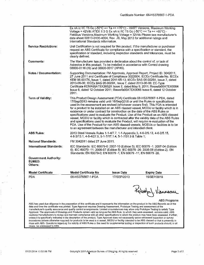
Certificate Number: 08-HS376567-1-PDA 21/JAN/2014
Confirmation of Product Type Approval Please refer to the "Service Restrictions" shown below to determine if Unit Certification is required for this product.
This certificate reflects the information on the product in the ABS Records as of the date and time the certificate is printed.
Pursuant to the Rules of the American Bureau of Shipping (ABS), the manufacturer of the below listed product held a valid Manufacturing Assessment (MA) with expiration date of 18/NOV/2014. The continued validity of the Manufacturing Assessment is dependent on completion of satisfactory audits as required by the ABS Rules.
And; a Product Design Assessment (PDA) valid untii16/SEP/2018 subject to continued compliance with the Rules or standards used in the evaluation of the product.
The above entitle the product to be called Product Type Approved.
The Product Design Assessment is valid for products intended for use on ABS classed vessels, MODUs or facilities which are in existence or under contract for construction on the date of the ABS Rules used to evaluate the Product.
ABS makes no representations regarding Type Approval of the Product for use on vessels, MODUs or facil ities built after the date of the ABS Rules used for this evaluation.
Due to wide variety of specifications used in the products ABS has evaluated for Type Approval, it is part of our contract that; whether the standard is an ABS Rule or a non-ABS Rule, the Client has full responsibility for continued compliance with the standard.
Product Name: Vortex Flow Measuring System Model Name(s): 88000
Presented to: ROSEMOUNT INC. 8200 MARKET BOULEVARD CHANHASSEN United States
Intended Service:
Description:
Ratings:
01/21/2014 12:52:06 PM
Measure Fluid Flow in Pipelines.
Flanged, Wafer, Reducer and Dual-Sensor, 0.5"-12" Line Sizes;
Temperature rating: -40 to 450• F (-40 to 232" C), Pressure Rating: 1600 psi. Output Signal: Digital HART signal - 4-20 rnA ; Optional Scalable Pulse Output -0-10 kHz, transistor switch closure w/ adjustable scaling up to 30 vdc, 120mA (maximum) ; Digital Foundation Fieldbus Signal - Manchester-encoded digital signal. Operating Temperature: -5o·c to 85 "C and -20"C to 85•c for flowmeters with local indicators. Power Supply: HART Analog - 10.8 to 30 vdc; Foundation fieldbus: 9 to 32 vdc, 17.8 rnA (nominal) 20mA (maximum). Intrinsically Safe for use in Class I, II and Ill, Division 1, Groups A. B, C, D, E, F and G: Temperature Class T4 Ta=70"C; Class 1, Zone 0 AEx ia IIC T4 Ta=70"C; Nonincendive for use in Class 1, Division 2, Groups A, B, C and D: Temperature Class T4 Ta=6o· c. Indoor and Outdoor (Type 4X) Hazardous Locations. Ex d [ia] IIC T6 Ga/Gb (integral transmitter) Ex d (ia Ga] IIC T6 Gb (remote transmitter) Ex ia IIC T6 Gb (remote sensor) Ex ia IIC T4 Ga (-60"C =< Ta =< +70"C)- HART Versions Ex ia IIC T4 Ga (-60"C =< Ta =< +60"C)- Fieldbus & FISCO Versions Ex nA ic IIC T5 Gc (-50"C =< Ta =< + 70"C)- HART Versions (-50"C =< Ta =< +60"C)- Field bus ATEX 111 /2 G Ex d [ia] IIC T6 Ga/Gb (integral transmitter) ATEX II 2(1) G Ex d [ia Ga] IIC T6 Gb (remote transmitter) ATEX II 1 G Ex ia IIC T6 Gb (remote sensor) ATEX 111 G Ex ia IIC T4 Ga (-60"C =< Ta =< +70. C) - HART Versions ATEX 111 G Ex ia IIC T4 Ga (-60"C =< Ta =< +60"C) - Fieldbus & FISCO Versions ATEX II 3 G
Copyright 2001 American Bureau of Shipping. All rights reserved. Page 1 of 2
Service Restrictions:
Comments:
Notes I Documentation:
Term of Validity:
ABS Rules:
National Standards:
International Standards:
Government Authority: EUMED: Others:
Model Certificate
PDA
Certificate Number: 08-HS376567-1-PDA
Ex nA ic IIC T5 Gc (-50°C =< Ta =< +70°C)- HART Versions, Maximum Working Voltage= 42Vdc ATEX 113 G Ex nA ic IIC T5 Gc (-50°C =< Ta =< +60°C)Fieldbus Versions,Maximum Working Voltage = 32Vdc Please see manufacturer's data sheet 00813-0100-4004, Rev. JB, May 2013 for additional ratings and International Standards information.
Unit Certification is not required for this product. If the manufacturer or purchaser request an ABS Certificate for compliance with a specification or standard, the specification or standard, including inspection standards and tolerances, must be clearly defined.
The Manufacturer has provided a declaration about the control of, or lack of Asbestos in this product. To be installed in accordance with Control drawing 08800-0116 (IS) and 08800-0017 (XP/IS).
Supporting Documentation: FM Approvals, Approval Report, Project ID: 3042011, 27 June 2011 and Certificate of Compliance 3022604. IECEx Certificate No. IECEx KEM 05.0017X, Issue 1, dated 2011-05-13; IECEx BAS 05.0028X, Issue 7, dated 2013-06-06; IECEx BAS 05.0029X, Issue 7, dated 2013-06-06; EC-Type Certificate KEMA99ATEX3852X Issue 2, dated May 9, 2011; Baseefa05ATEX0084 Issue 6, dated 12 October 2011; Baseefa05ATEX0085 Issue 6, dated 12 October 2011.
This Product Design Assessment (PDA) Certificate 08-HS376567-1-PDA, dated 17/Sep/2013 remains valid untii16/Sep/2018 or until the Rules or specifications used in the assessment are revised (whichever occurs first). This PDA is intended for a product to be installed on an ASS classed vessel, MODU or facility which is in existence or under contract for construction on the date of the ASS Rules or specifications used to evaluate the Product. Use of the Product on an ASS classed vessel, MODU or facility which is contracted after the validity date of the ASS Rules and specifications used to evaluate the Product, will require re-evaluation of the PDA. Use of the Product for non ASS classed vessels, MODUs or facilities is to be to an agreement between the manufacturer and intended client.
2013 Steel Vessels Rules 1-1-4/7.7, 1-1-Appendix 3, 4-6-2/5.13, 4-6-2/5.15, 4-8-3/13.1,4-8-4/27.5,5-1-7/17.1.4,5-1-7/31.9 & Table 1;
FM 3042011 dated 27 June 2011.
IEC Standards: IEC 60079-0:2007-10 (Edition 5); IEC 60079-1:2007-04 (Edition 6); IEC 60079 -11: 2006-07 (Edition 5); IEC 60079-26: 2006-08 (Edition 2). EN Standards: EN 60079-0; EN 60079 -1; EN 60079 -11; EN 60079 -26.
Model Certificate No Issue Date Expiry Date
08-HS376567-1-PDA 17/SEP/2013 16/SEP/2018
ASS Programs ABS has used due diligence in the preparation of this certificate and it represents the infonnation on the product in the ABS Records as of the date and time the certificate was printed. Type Approval requires Drawing Assessment, Prototype Testing and assessment of the manufacturer's quality assurance and quality control arrangements. Limited circumstances may allow only Prototype Testing to satisfy Type Approval. The approvals of Drawings and Products remain valid as long as the ABS Rule, to which they were assessed, remains valid. ABS cautions manufacturers to review and maintain compliance with all other specifications to which the product may have been assessed. Further, unless it is specifically indicated in the description of the product; Type Approval does not necessarily waive witnessed inspection or survey procedures (where otherwise required) for products to be used in a vessel, MODU or facility intended to be ABS classed or that is presently in class with ABS. Questions regarding the validity of ABS Rules or the need for supplemental testing or inspection of such products should, in all cases, be addressed to ABS.
01/21/2014 12:52:06 PM Gopyright 2001 ·~~~rican Bureau of Ship~:ng. A~ I rights rese;v~d. Page 2 of 2

REVIEWED
Details of this review are as indicated in the
ABSietter
~I/;_ ~ HINDLEPDWER
Quality and Integrity - Our Passion INCORPORA fE~
CDSOOB-00 1075 Saint John Street • Easton, PA 18042-6661
Phone 610.330.9000 • Fa~ 610 330 8510 www.hindlepo~erinc.com
PRODUCTION TEST INSTRUCTIONS
REV
0
1
2
3
4
AT SERIES 00j Microprocessor-Controlled ~
FLOAT BATTERY CHARGER (lj
r. AT1 0.1 Single Phase Input- GroLJtp"L(6-25 Adc)
AT10.1 Single Phase Input- Grq_dp II (30-100 Adc)
AT30 Three Phase lnp~t (25-1000 Adc)
. DATE DCNNo DES~RIPTION REVISED APPROVED
.. - BY BY 09/24/2003 El397 Rev. 0 rele'ase MCR Ted H.
08/23/2007 20810 see E§~# 20810 for Rev. 1 changes MCR ND
12/03/2009 21923 I • S~e ,~'CN# 21923 for Rev. 2 changes MCR ND 1:-
' ~ r-
..

REVIEWED
~' ''~ HINDLEPIIHIER
Quality and Integrity - Our Passion
Details of this review are as indicated in the
ABSietter INCORPORATED
CD5008-00 ~ABS 1075 Saint John Street • Easton, PA 18042-6661
Phone 610.330.9000 • Fa)( 610 330 8510 www.hindleoowerinc.com
1.0
2.0
3.0
TABLE OF CONTENTS ~ PURPOSE ................... ............... ..... ................. ......................................................................... .............. 1
REFERENCE DOCUMENTS ........................................................................................ ......................... 1
TESTING A STANDARD CHARGER .......................................................................... ......................... 1
3.1.
3.2.
3.3.
Dielectric withstand test................................................................................... . . . ............................... 1
Connecting circuit board assemblies....................................................... . .... . ............ ................. ....... 1
Setting up the test bench. .................................... ............................... . ........... .. ................................ . 2
3.4. Testing the front panel controls..................................................... ...... . ........ .. ................................. 2
3.4.1. AC ON indicator .................................................................................................... ..... .................. 2
3.4.2. Lamp Test key ................................................................. .......................................................... 3
3.4.3.
3.4.4.
3.4.5.
3.4.6.
3.4.7.
3.4.8.
3.4.9.
~:::~i:eM~:~h~:y~~;::::::::::::::::::::::::: :: :::: ::::::::::::::::· : · ::.) ::::::::::::::::::::::::::::::::::::::::::::::::::::::::::: ~ Meter Mode key.. .............. ..... ............ .... ............. .. . ................ ..................... ....................... ...... ... 3
Ammeter accuracy..................... .......... .. ....... . .. . .......................................................................... 3
Edit key operation...................................... .. .............. ............................................ ...................... 4
Current Limit setting (old key combination) ................................................................................. 4
High Voltage DC Shutdown operation . .. .............................................................................. ... 4
3.5. Testing the internal functions ......... ....... ........... .............. .. ... ..... ........ ..... .. ..... ..................... ................... 4
3.5.1. Testing the front panel disable jumRer .......................................................................................... 4
3.6. Testing current limit................... . ..... ................ ..................... ...... ...................................... ................ 5
3.7. Measuring ripple voltage ................................................................................................................... 6
3.8. Measuring the voltage regulation ......................................................................................................... 7
4.0 TESTING ALARMS AND INSTALLED OPTIONS ................................... ............................................... 8
4.1. Testing Built-in (Prima'Y) Alarms .......................................................................................................... 8
4.1.1. High DC Voltage Alarm .. .. ... ..... ..... ..... ...... ... ......... .... ............... .............. .............. .................... ...... 8
4.1.2. Low DC Voltage Alarm .................................................................................................................. 9
4.1.3. AC Input Failure Alarm ................. .......... ............................... ....................................... ................. 9
4.1.4. Positive Gro und Fault .................................................................................................................... 9
4.1.5. Negative Ground Fault ........................ .. : ............................ ........................................................... 9
4.1 .6. Disabling Ground Fault Detection .... ................. .... .... ... ..... .................................. .......... .............. 10 5.0 STORING FINAL SETTINGS .... .......... ..................... ............................................................................. 1 0
5.1. Voltage and current settings .. .. ........ .. ........... ...................... .... ....................................... ..................... 1 0
5.2 Voltmeter calibration ............................... ....................... ................................ ............... ....... ............... 11
5.3. Order Completion ............................. ...... ................................................................... ........ .... ............. 11
C05008 OO.Rev.2.AT.Prod.Test.lnst.doc Rev. 2 Last Printed 12/3/2009 5:49:00 PM

REVIEWED
Quality and Integrity - Our Passion
Details of this review are as indicated in the
ABSieUer
- - "' .. \. 1075 Saint John Street • Easton, PA 18'042-6661
CD5008-00 . Phone 610.33q.900Q. · · Fax 61Cl 330ffi10 ·.: _ ~ .. www.tiindlepo""Werinc.com .. _ ·-· .
1.0 PURPOSE This procedure defines the production test methods and parameters for the AT ~eri'es Battery Charger product line.
2.0 REFERENCE DOCUMENTS NEMA PES-1996 - Stationary Battety Chargers
DI5008-00 - AT Series Battety Charger- Production Test Data S~J.eet
3.0 TESTING A STANDARD CHARGER 3.1. Dielectric withstand test
• Disconnect all printed circuit boards from the chargel.i wiring harness(es).
• Place a jumper across the de ftlter capacitors (Cl, C2J . • • Disconnect the ground lead of the noise suppression capacitors (C4, CS), on the de tenninals
• •
•
•
of the I/0 panel.
Disconnect the lightning arrestor ground wire (if installed) .
Apply a test voltage of 2500 Vrms for ¥jeast one second between the following points:
AC input voltage terminals to chassis
AC input terminals to de outp,ut terminals
Apply a test voltage of2500v.Yrms fm at least one second from the de output tem1inals to chassis.
Enter the test results on the"t~st data sheet.
• Remove jumpers attached'to filter capacitors (Cl, C2) and reconnect the components that were disconnected in step 3 .1.
3.2. Connecting circuit1 b•oard assemblies
• Locate U6 at the bottom of the main control PC Board.
• Record tlie program version number on its label in the space provided on the test data sheet.
• Install a <Vor connect the control circuit board, the gate drive board(s), and any other boards requiiedon the order. Verify that all circuit boards are connected to the conect wire
~r
hamesi ( es ).
Note: If the charger has been ordered with the auxiliary relay board option, verify that the j:tJfnper on J4 is in the position corresponding to the charger de voltage rating. If the charger is turned on with the jumper in the incorrect position, damage may occur.
Q(l) g CD5008 OO.Rev.2.AT.Prod.Test.lnst.doc Rev. 2 Last Printed 12/3/2009 5:49:00 PM

Quality and Integrity - Our Passion
REVIEWED
Deta•ls of this review are as indicated •n the
ABS ieUer
~· ''& ~ HINDLEPDWER
INCORPORATED
CD5008-00 1075 Saint John Street • Easton, PA 18042-6661
Phone 610.330.9000 • Fax 610 330 8510 www.hindlepowerinc.com
3.3. Setting up the test bench
• Compare the main transformer (Tl) jumpers with the connection table:
RATED INPUT VOLTAGE (VAC) JUMPER LOCATIONS AT10.1
120 H1 - H3 H2 H5 Battery Chargers
208 H2 - H4 (both jumpers)
240 H2 - H3 (both jumpers) Single Phase
480 none Input
other (custom Vac) consult Engineering
RATED INPUT VOLTAGE (VAC) JUMPER LOCATIONS AT30
120 '"'-
not available Battery Chargers
208 ~., H1, H2 & H3 to 1
Three Phase 240 ....... ~ H1, H2 & H3 to 2
480 none Input
other (custom Vac) consult Engineering
• Vetify that the ac supply voltage from the test bench matches the ac input voltage tapped on the transformer.
• Verify that the de battery voltage of the bench matches the de output voltage printed on the order.
• If the charger is unfiltered, connect the test load capacitor bank for all measurements, except where noted in the procedure.
3.4. Testing the front panel controls
• Close CB2, then close CB1.
• Adjust the ac ·input voltage to nominal.
• Connect resistive load to obtain approximately 50% of rated de load cunent.
Watch the charger front panel display and verify that it progresses through the initialization and soft start procedures. Vetify that the following indicators and controls operate as specified. For each step, enter the results on the test data form.
3.4.1. AC ON indicator
• Verify that the "AC ON" indicator (green) is lit.
~ (b
0 CD5008 OO.Rev.2.AT.Prod.Test.lnst.doc 2 Rev. 2 Last Printed 12/3/2009 5:49:00 PM

~\. \!~ ~ HINDLEPDHIER
REVIEWED
Quality and Integrity - Our Passion
Deta1ts of this review Qre as Indicated in the
ASS feller /NCORPORA ~E~
CDSOOB-00 1075 Saint John Street • Easton, PA 18042-6661\•
Phone 610.330.9000 • Fax 610 330 8510 www.hindlepowerinc.com
3.4.2. Lamp Test key
• Press the LAMP TEST (down an ow) key; verify that all front panel indicators(ligbt, and the display shows 8888. Hold the key for at least 4 seconds, and verify that the1co'Illffion alarm relay transfers (measure at TBJ at the bottom left of the control PC board). Iftlie optional auxiliaty relay board is installed, also velify that all alatm relays on that poard transfer. When you release the key, verify that the indicators and display retw to tHeir previous state, and the common alarm relay and optional auxiliaty relays retum to :tliepon-alarm state. After you release the key, the program version appears on the display for>2~econds. Check this number against the version number you recorded on the test da a sljeet in step 3.2.
3.4.3. Charge Mode key
• Press the CHRG MODE key; verify that the charger changes 'from float to equalize.
3.4.4. Equalize Method key
3.4.5.
3.4.6.
• Press the EQLZ MTHD key. Velify that the charge changes from ~annal timer to manual equalize method. If the charger is not initially il{, ~e manual timer method, press the EQLZ
MTHD key repeatedly until it is.
•
•
•
•
•
•
•
•
Press the EQLZ MTHD key again; verifY that the charger changes from manual equalize to auto equalize timer method.
Press again; vetify that the charger. changes back to the manual timer method .
Meter Mode key
Press the METER MODE k'ex.'Verify that the charger displays only the output voltage, and the Volts indicator is steady.
Press again. Verify th~t tl~e meter now displays only the output current, and the Amps indicator is steady.
Press again. V ~rify that the meter displays only the equalize time remaining, and the Time indicator is steady
Press the METER! MODE key one last time. Verify that the display alternates from de volts to de amps tmJime remaining.
Press the CHARGE MODE key to return the charger to float mode .
A.mnieter accuracy
Press the METER MODE key until the display locks on de amps .
C•, Compare the measured de output cunent of the charger with the current displayed on the front panel. Verify that the difference between measured and displayed current is within the tolerance noted on the test data sheet. fJ
e(h g CD5008 OO.Rev.2.AT.Prod.Test.lnst.doc 3 Rev. 2 Last Printed 12/3/2009 5:49:00 PM

I I
REVIEWED ~' '~ ~ HINDLEPIJWER
Quality and Integrity- Our Passion
Oeta.ls or this revoew are as lodiC3ted '" the
A8S lener INCORPORATED
CD5008-00 1075 Saint John Street • Easton, PA 1804Z-ll661
Phone 610.330.9000 • Fax 610 330 8510 www.hindfeoowerinc.com
3.4. 7. Edit key operatiou
3.4.8.
• Press the EDIT key.
•
•
•
•
•
•
•
•
Verify that the charger enters the edit mode. The Volts and Float indicators should be flashing, and the float voltage should be flashing on the display.
Press the UP and DOWN anow keys repeatedly. Verify that the displayed parameter changes accordingly.
Press and hold the UP arrow key; verify that the displayed value stops flashing and increases continuously. Repeat with the DOWN arrow key.
Press the EDIT key repeatedly until charger exits the edit mode .
Current Limit setting (old key combination)
Press and hold the UP anow key, then press the EDIT key. Verify that the charger enters the cunent limit edit mode.
Press the UP and DOWN anow keys repeatedly. Verify the current limit setting changes accordingly.
Set the current limit to 100% of rated output current, then press the EDIT key and verify that the charger exits the current limit edit mode.
Enter the current limit mode again. Verify that it is set to 100%. Change the setting to 110%, then press the EDIT key to exit the current limit edit mode.
3.4.9. High Voltage DC Shutdowu operation
• Press and hold the up arrow key, then press the CHRG MODE key. Release both keys; note that the display shows "OFF" or "On." The display toggles between "OFF" and "On" each time you press the UP or DOWN key. Press the key until"OFF" appears on the display. Wait for the charger to return to normal operation; this should take approximately 6 seconds.
3.5. Testing the internal functions
3.5.1. Testing the front panel disable jumper
• Locate the front panel disable jumper, J9, in the middle right side of the control PC board (as viewed from the rear).
• •
•
{9.
Move P9 to the "DISABLE" position (linking the two top pins) .
Press the EDIT key on the front instmment panel and verify that the charger does not enter the edit mode.
Press the EQLZ MTHD key on the front insttument panel and verify that the charger does not change equalize mode.
Press the LAMP TEST key and verify that aU indicators, and all segments of the numeric display, light.
CD5008 00. Rev .2 .AT. Prod.Test.lnst.doc 4 Rev. 2 Last Printed 12/3/2009 5:49:00 PM

Cj
Quality and Integrity- Our Passion
CDSOOS-00
REVIEWED
DetaJis of this review are as indicated in the
ASS letter
PABS • 1075 SaintJohn Street • Easton, PA 180~2-6661
Phone 610.330.9000 • Fax 6 \_C/:3.30 8510 www.hindlerxiWen"nc.com
• Replace P9 in the "ENABLE" position (linking the two lower pins).
• Enter the results on the test data sheet.
3.6. Testing current limit
Note: The parameters for this test are independent of the battery type noted on the order acknowledgment. For this test, you will measure ac input cmTent (using an rins-responding meter), de output voltage, and de output current.
• Connect the capacitor bank to the output, then disconnect the b~ttecy bank.
• Press and hold the up arrow key, then press the EDIT key, or,. en er the edit mode nonnally, and press EDIT until you reach the current limit adjustment:, wfi.ich is the sixth parameter. Use the UP and DOWN keys to adjust the current limit Jo~the)value shown in the table below.
• Press the EDIT key to save the cunent limit value an9t reJlirn the charger to nonnal operation.
AT10.1 -Group I AT10.1 -Group II AT300UTPUT CURRENT TOLERANCE OUTPUT RATING OUTPUT RATING RATING LIMIT
(A) (Ad c) (Ad c) (Adc) (A)
6 n/a ... n/a 6.6 ±0.33
12 n/a r ,;, n/a 13.2 ±0.66
16 n/a - n/a 17.6 ±0.88 . 20 n/a
~ n/a 22.0 ±1.1
25 n/a ~ 25 27.5 ±1.4
n/a 30' ·c... -~ 30 33.0 ±1.7
n/a 40 ...... 40 44.0 ±2.2
n/a 50 50 55.0 ±2.8
n/a 75 75 82.5 ±4.1
n/a ' 100 ... 100 110 ±5.5
n/a II.. n/a 125 138 ±6.9
n/a I'
n/a 150 165 ±8.3 -n/a> '......_ n/a 200 220 ±11.0
r'lla - n/a 250 275 ±13.8
n/a1 n/a 300 330 ±16.5
t.. ( .i'dta n/a 400 440 ±22.0
~ n/a n/a 500 550 ±27.5
~ n/a n/a 600 660 ±33.0
J n/a n/a 800 880 ±44.0
n/a n/a 1,000 1,100 ±55.0
~ -0 Set the charger to FLOAT mode. Record the flo&t voltage on the test data sheet.
CD5008 00. Rev .2 .AT. Prod.Test.l nst.doc 5 Rev. 2 Last Printed 12/3/2009 5:49:00 PM

I I
REVIEWED
Details of this review are as indicated •n the
ASS tetter
.::::.,\.1//..- ~ HINDLEPDWER
Quality and Integrity- Our Passion /NCORPORA TED
CDSOOB-00 1075 SaintJohn Street • Easton, PA 18042-6661
Phone 610.330.9000 • Fax 610..330 8510 www.hindlepowerinc.com
• Add resistive load to the charger until the output voltage starts to decrease. Continue to add resistive load until the output voltage reaches the end voltage shown in the table below. Verify that the output current is within the tolerance shown in the table above. It may take a few seconds for the charger to stabilize at the current limit value after each load change.
DC VOLTAGE RATING END VOLTAGE (Vdc)
12 10.5 ) 24 -~ 21.0
48 42.0 ) -130 105
J. r: . • Record the de output voltage, the de output cunent, and the c mput current on the test data sheet.
• Reduce the resistive load to obtain rated (100%) out}J,ut current.
3.7. Measuring ripple voltage Conditions: Nominal ac input voltage, float mode, rated output cunent
Connect battery, disconnect capacitor bank.
• Using an nus-responding ac millivoltmeter, measure the ripple voltage at the battery terminals. If the charger current rating is greater than 1,4 of the battery AH rating, then adjust the measured value using the formula:
Adjusted Ripple-= Batt AH x Measured Ripple . 4 x ADC Rating
• For filtered chargers only: disconnect the batte1y, and measure the ripple voltage at the charger output terminals. Do not adjust this reading.
• Verify that the ripple voltage is within the limits shown in the table below.
CHARGER CONDITION RIPPLE VOLT AGE LIMITS, mV rms
TYPE 12VDC 24VDC 48VDC 130VDC
WITH BATTERY 250 (typ.) 500 (typ.) 1000 (typ.) 2600 (typ.)
UNFILTERED (at battery terminals)
I .._ WITHOUT BATTERY DO NOT MEASURE , I' WITH BATTERY
(at battery terminals) 30 30 30 100
FILTERED WITHOUT BATTERY 130 (typ.) 250 (typ.) 500 (typ.) 1320 (typ.)
~ (at charger output terminals}
WITH BATTERY 30 30 30 100
ELIMINATOR (at battery terminals)
WITHOUT BATTERY 30 30 30 100
(at charger output terminals)
1 Ripple value is adjusted for a battery AH four times the charger rating.
CD5008 OO.Rev.2.AT.Prod .Test.lnst.doc 6 Rev. 2 Last Printed 12/3/2009 5:49:00 PM
I I
Quality and Integrity - Our Passion
CD5008-00
REVIEWED
Details or this review are as indicated in the
ABS ielter
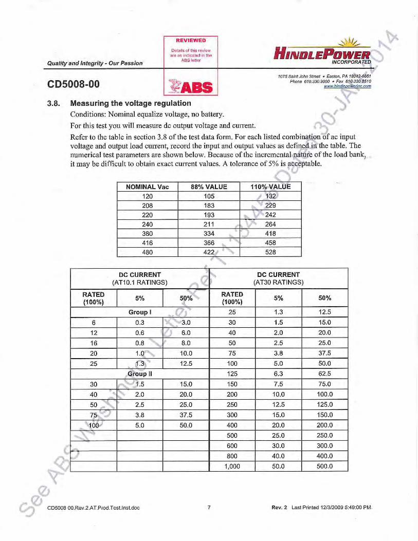
3.8. Measuring the voltage regulation
Conditions: N aminal equalize voltage, no batte1y.
' 1075 SaintJohn Street • Easton, PA 180'4~6661 Pflone 610.330.9000 • Fax 610..330 8510
www.hindlepowerinc.com
For this test you will measure de output voltage and cmTent.
Refer to the table in section 3.8 of the test data form. For each listed combinafon of ac input voltage and output load cunent, record the input and output values as defmeo in'the table. The numerical test parameters are shown below. Because of the incremental.nature of the load bankJ it may be difficult to obtain exact current values. A tolerance of 5% is ,ac((eptable.
" j
NOMINAL Vac 88% VALUE 110%-VALUE
120 105 ' 13?) 208 183 ,.. r 229
220 193 ....... 242
240 211 264
380 334 418
416 366 ~
' 458
480 422, ...
528
DC CURRENT Q ~ DC CURRENT (AT10.1 RATINGS) (AT30 RATINGS)
RATED 5% 5~%
RATED 5% 50%
(~00%) (100%)
Group I ' .. 25 1.3 12.5
6 0.3 1"' ·:#3.0 30 1.5 15.0
12 0.6 6.0 40 2.0 20.0
16 0.8 8.0 50 2.5 25.0
20 1.0,. ......... 10.0 75 3.8 37.5
25 ' 1--:3f 12.5 100 5.0 50.0
G·roup 11 125 6.3 62.5
30 .) 11.5 15.0 150 7.5 75.0
40 - ·' - 2.0 20.0 200 10.0 100.0 1 ...
50 .., " 2.5 25.0 250 12.5 125.0
7,5 3.8 37.5 300 15.0 150.0
~1001 5.0 50.0 400 20.0 200.0
• ...__ 500 25.0 250.0
- 600 30.0 300.0
800 40.0 400.0
1,000 50.0 500.0
CD5008 OO.Rev.2.AT.Prod.Test.lnst.doc 7 Rev. 2 Last Printed 12/3/2009 5:49:00 PM-

REVIEWED ~\/./...-- ~ HINDLEPDWER
Quality and Integrity- Our Passion
Oeta.ts olthts review dre as indicated on lhe
ABSteuer INCORPORATED
CD5008-00 1075 Saint John Street • Easton, PA 18042-6661
Phone 610.330.9000 • Fax 6 10 330 8510 www.hindleoowerinc.com
• Calculate the voltage regulation using the equation below. Verify that the regulation is within ± 0.25%. Enter the result into the appropriate section of the test data fom1.
% Deviation = 50 X (V max - V min) + (V nom)
where Vnom is the nominal equalize voltage, Vmax is the highest voltage measured during the test, and V min is the lowest voltage.
4.0 TESTING ALARMS AND INSTALLED OPTIONS
4.1. Testing Built-in (Primary) Alarms
4.1.1. High DC Voltage Alarm
Conditions: Float mode, nominal Vac, about 10% load.
• Enable HVDC Shutdown. See section 3.4 9
• Press the EDIT key until the equalize voltage appears on the display. Record the equalize setting.
• Press the EDIT key twice more until the HIGH DC VOLTAGE lamp is lit. Adjust the high DC Voltage Alarm level to a value 1 OV less than the equalize setting.
• Press the EDIT key three more times to return the charger to normal operation.
• Set the charger to the equalize mode.
• Verify that the HIGH DC VOLTAGE alann indicator lights. This may take a few seconds.
• Wait 30 seconds, and verify that the common alarm relay on the control PC board transfers (measure at TB3 at the bottom left of the board). If the optional auxiliaty alatm board is installed, verify that the HVDC alann relay contacts transfer. Also verify that the charger shuts down, and the front panel display shows E 03.
• Tum CB 1 (or external ac power) off for 5 seconds, then on to restart the charger.
• Reset the High DC Voltage alarm so that it is higher than the equalize voltage.
• Disable HVDC Shutdown.
• Enter the results on the test data sheet.
9;)0 ~
(lJ
0 CD5008 OO.Rev.2.AT.Prod.Test.lnst.doc 8 Rev. 2 Last Printed 12/3/2009 5:49:00 PM

REVIEWED ~'~ ~ HINDLEPIIWER
Quality and Integrity- Our Passion
DetailS of this review are as indicated in the
ABSieuer INCORPORA~E~
CD5008-00 1075 Saint John Street • Easton, PA 1804276661'1,
Phone 610.330.9000 • Fax 610.330·8{>10 www.hindleooWerinc.com
~ ...
4.1.2. Low DC Voltage Alarm
4.1.3.
4.1.4.
Conditions: Equalize mode, nominal Vac, about 10% load. ~
• Press the EDIT key until the float voltage appears on the display. Record the float setting.
• Press the EDIT key three more times until the LOW DC VOLTAGE lamp .. is lit. Adjust the low DC Voltage Alann level to a value l.OV higher than the float setting.
• Press the EDIT key twice more to retum the charger to nmmal operatiq_n.
• Set the charger to the float mode.
• Verify that the LOW DC VOLTAGE alarm indicator lights. Tp.is may take a few seconds.
• Wait 30 seconds, and verify that the common almm relay; ·on the control PC board transfers (measure at TB3 at the bottom left of the board). If the opti,gp.al auxiliary alann board is installed, also verify that the L VDC alann relay contacts transfer.
• Readjust the Low DC Voltage Alarm so that it is lower than the float voltage.
• Enter the results on the test data sheet.
• •
•
• • •
AC Input Failure Alarm
Conditions: Float mode, nominal Vac, 1!)% load, battery connected .
Open CB1 and verify that the AC INPUif1FAILURE indicator lights. This may take a few seconds.
Wait 30 seconds, and verify that the common alarm relay on the control PC board transfers (measure at TB3 at the bottom eft of the board).
" Close C81. Verify that the ' ac. input failure almm resets .
Enter the results on the test dhta sheet.
Disconnect the battexy from the output.
Positive Ground-Rault Conditions: Floatl.mode, nominal Vac, 10% load, no batte1y.
• Tum offal_l p_ower to the charger. Open CB1. On the 1/0 panel, TB1 , connect an extemal lOK Oht.ii're~stor between the GND and(+) DC Output terminals.
• Reapply~power and close CB1.
• Verify' that the POS GND indicator lights .
• c
ait 30 seconds, and verify that the common alarm relay on the control PC board transfers (measure at TB3 at the bottom left of the board).
Enter the results on the test data sheet. •
4:1:5'. Negative Ground Fault
• Repeat step 4.1.4, except cmmect the lOK Ohm resistor between GND and (-) DC Output.
Leave the resistor cmmected for the next step.
CD5008 OO.Rev.2.AT.Prod.Test.lnst.doc 9 Rev. 2 Last Printed 12/3/2009 5:49:00 PM

REVIEWED ~\1& ~ HINDLEPDWER
Quality and Integrity- Our Passion
Details or thos review are as indicated in Hle
ASS letter INCORPORATED
CDSOOS-00 ~-11!1~ · --~
1075 Saint John Street • Easton, PA 18042-6661 Phone 610.330.9000 • Fax 610 33()_8510
www.hindfeoowerinc.com
4.1.6. Disabling Ground Fault Detection
5.0
Conditions: Float mode, nominal Vac, 10% load, no battety.
• Open CB1.
• Locate jumper J5 on the left edge of the control PC board, near the top, as viewed from the rear.
• Move P5 to the DISABLE position.
• Close CB1.
• Verify th?-t the NEG GND indicator is not lit.
• Open CB1, and return P5 to the ENABLE position.
• Enter the results on the test data sheet.
STORING FINAL SETTINGS This portion of the test must be completed in one session. Any interruptions may result in lost parameter data.
Conditions: Float mode, nominal Vac, 50% load. !=onnect battery.
5.1. Voltage and current settings
• Enter the edit mode. Adjust the charger operating parameters as indicated in the tables below.
ell
VOLTAGE FACTORY SETTINGS RATING FLOAT EQUALIZE EQLZTIME HVDC ALARM LVDC ALARM
12 13.0 -. 14.0 14.4 12
24 26.0 28.0 28.8 24 24 hours
48 52.0 56.0 57.6 48
130 1 31~0 139.0 144.0 120
OUTPUT RATING CURRENT LIMIT (Ad c) 1- (A)
OUTPUT RATING CURRENT LIMIT (Ad c) (A)
6 -~·~ 6.6 125 138
12 ~ 13.2 150 165
16 ,
17.6 200 220 20...., 22.0 250 275
25 27.5 300 330
- 30 33.0 400 440 ._, 40 44.0 500 550 I 50 55.0 600 660
75 82.5 800 880
100 110 1,000 1,100
CD5008 OO.Rev.2.AT.Prod.Test.lnst.doc 10 Rev. 2 Last Printed 1213/2009 5:49:00 PM

~.... . . ....
REVIEWED ~"· \ !/,... ~ HINDLEPOHIER
Quality and Integrity- Our Passion
Detatls of this re~~iew are as indicated in the
ABSielter · INCORPORA~ED\ ..
,..
CDSOOB-00 11 . ..:.._ass 1075 Saint John Street • Easton, PA 18042:6661
Phone 610.330.9000 • Fax 610 33M510 www.hind/epo~rinc.com
•
•
\-Exit the edit mode.'P~ess and hold the up anow key, then press the CHRG MODE keY.~If necessary, press the CHRG MODE key again until "OFF" appears in the front .panel display. Wait a few seconds for the charger to return to normal operation.
Reduce the connected load to 10%. Keep the battery connected .
5.2. Voltmeter calibration
• Press the METER MODE key to lock the display on de volts.
•
•
• •
Compare the measured de output voltage of the charger (at TBJ} with the voltage displayed on the front paneL Verify that the difference between measured cwd displayed voltage is within limits (±0.25%):
(
CHARGER ' I!!IMITS DC VOLTAGE RATING • (Vdc)
12 ' ± 0.030
24 "
± 0.060
48 ~· ± 0.120
130 . "' ± 0.325 ~
-r....
If the voltmeter is not with the abo:ve;li~its, press and hold the UP key, then press the EQLZ MTHD key. The display flashes the ovtput voltage value. Press the UP or DOWN key to increase or decrease the charger ·81,1tput voltage until it agrees with the voltmeter. Wait a few seconds for the charger to rew~to normal operation.
Enter the results on the tesf oata sheet. · ) .
Tum off the charger; disconnect the battery and remove all power sources .
5.3. Order Completion
• Record results of~ tests and calibration steps, mechanical inspection, and the 'ORDER COMPLETIO .sm:tion of the test data sheet.
• Check that al~t;,der options and accessories have been tested and approved for shipping. For accessorib not listed, write the part number and description in the table.
~ The Aq~Series Battery Charger test is now complete.
9:;(/_) ~
0 , g CD5008 OO.Rev.2.AT.Prod.Test.lnst.doc 11 Rev. 2 Last Printed 12/3/2009 5:49:00 PM

REVIEWED
Details or th1s review are as indicated in the
ABS letter HINDLEPDHIER' ... a World Class Organization INCORPORATED,
JF5036-00 1075 Saint John Street • Easton, PA- 8042 661
Phone 610.330.9000 • Fax~10.330.9000 www.hindliQOWerinc.com
STANDARD SAMPLE SPECIFICATION
AT30 Series Microprocessor-Controlled Float Battery Charge!) (three phase input)
A battery charger shall be fumished in accordance with the following specification:
1.0 - General
1.1 -The battery charger shall be sized to continuously carry the load demand as required in the plans, and have sufficient reserve capacity as deemed appropriate for. the application.
1.2 - The battery charger shall provide a continuous regulated DC output derived from an AC source. The output shall be suitable to maintain the battery in a fuJly charged state, while supporting any additional DC loads as defined in the plans. The battery charger shall also have the ability to automatically or manually provide an equalizing charge as required for recharging the battery after discharge.
1.3 -The battery charger shall be of a design that employs microprocessor technology to control and define all critical operational, calibration, regulation and alarm functions.
2.0 - Applicable Codes
The AT30 Charger product line meets the requirements of the designated versions of the following industry and agency standards:
• NEMA PES-1996 Stationary type battery chargers
• UL 1564
• UL 1012
Standard for industrial battery chargers
Standard for stationary power supplies
• CSA 22.2 Standard for battery chargers
• ANSI C3 J.90-1989 Surge withstand capability definitions and tests
• IEC 146 Semiconductor converters
• FCC Part 15 Subpart J Class A
3.0- Standard Features
3 .I Standard Three Phase Input Voltages include 208, 240 and 480Vac 60Hz. Other input voltages such ;,ts 220, 380 and 416Vac 50/60Hz and 575Vac 60Hz are available options.
3..~ Standard Output Voltages include 12, 24, 48 and 130V de with output currents ratings ranging from 25 to 1,000 Adc, depending on charger output voltage rating .
00 0 JF5036 OO.doc Sheet 1 of 8 ~ev. 0 Last Printed 1/31/2005 10:13 PM

... a World Class Organization
JF5036-00
REVIEWED
Detaas of this review are as indicated in the
ABS letter
~ ~~~ ~~ HINDLEPDWERt '
INCORPORA TEq
1075 Saint John Street • Easton, PA£<80~661 Phone 610.330.9000 • Fax.,I!,!_0.33Q.9000
\N"'IVW. hindleeo~ erinc.com
' 3.3 -Output control is constant-voltage, current-limited. Flat temperature coefficient of ou~pjit voltage is standard. An optional battery temperature probe is available for temperature compensation of the output voltage. The probe is compatible with Lead-Acid and Ni-Cad battery cype~.
3.4 - The AT30 charger is capable of delivering 100% rated output current at thel!,maximum stated equalize voltage and at the minimum rated ac input voltage, at 50 °C.
3.5- Current limit adjustable from 50 to 110%; factory set to 110%. The cutT'ent limit specification does not mean that the charger will be able to deliver greater than 1 Q,O% r.llied output current under all operating conditions.
3.6- Meets the SWC (oscillatory surge) requirements of ANSI (~3].90, and the transient suppression levels for category Bin IEEE Std. 28/ANSI C62.1.
3. 7 - Full wave six -pulse rectifier bridge with free-whe~ mg 'diode, single-winding transformer secondary, and de inductor.
3.8 - AC input circuit breaker, CB 1, is standard·~ fuses may be specified in place of an input circuit breaker at no charge, or fuses can be added in cdnjunction with the input circuit breaker to achieve higher AIC ratings.
3.9 - DC output circuit breaker, CB2, is st~ndard. Fuses may be specified in place of an output circuit breaker at no charge, or fuses can b~ aldded in conjunction with the output circuit breaker to achieve higher AIC ratings.
3.10 -Starts and operates witli a crowbar short circuit on the output without tripping the standard de circuit breaker. A filtered ~qarger equipped with de fuses may clear the fuses in the event of a crowbar short circuit dur':i:fg operation, caused by the filter capacitors discharging through the fuses.
3.11 -No blocking dioJie is provided. A blocking diode is not required, since a de circuit breaker is standard. The dc1161ld on the battery (without optional equipment) during an ac power failure is less than 0.5 A.
3.12- Survi ves a reverse polarity battery connection. The standard circuit breaker trip-s through the free-wbe~l~n{ diode on unfiltered chargers; a polarity diode is included with filtered chargers to protect th~ output capacitors.
3).f3 Cooling: Natural convection for ~11 ratings through 300 Adc in NEMA 1 enclosures. NEMA 4 enplosures may have forced air-cooling' for those ratings. Power for the cooling fans is provided internally.
00 g JF5036 OO.doc Sheet 2 of 8 Rev. 0 Last Printed 1/31 /2005 10:13 PM

... a World Class Organization
JF5036-00
REVIEWED
Details o f this review are as indicated on lhe
ABSlelter HINDLEPDWER" INCORPORATED
1075 Saint John Street • Easton, PA 8042 661 Phone 610.330.9000 • Fax 610.330.9000
YIWW.hindlepo erinc.com
3.14- Solderless CU-AL compression input and output terminals, including chassis ground
3.15 - A clear safety cover over all internal components. The safety cover is marked with an intemal wiring diagram.
3.16 - Remote sense terminals.
3.17 - Switchboard wiring is standard, using Hypalon or XLPE (cross-linked polyethylene) insulation system, 600V, 105 °C, except for PC board interconnections, whicb__may use ribbon cable assemblies, or other standard industrial grade PC board interconnections.-XLPE insulation is rated for the UL VW -1 vertical wire flame test.
3.18- Test points are provided for semi-automatic final test.
4.0 - Operation
4.1 - Battery charger shall automatically ~etermine the appropriate DC output, in tenns of either voltage or current required for maintaining the battery and load either by pre-programming or in-field re-programming, via the touch panel controls.
4.2 - The battery charger shall automatically know and respond to any alarm options or remote sensing options installed according to the manufacturer's instructions without further operator action.
4.3 -The battery charger shall display) via a 1% digital display and associated LED indicators, all functions impot1ant to operation.
4.3.1 - During float operation, the digital display shall altemate between DC voltage and DC cunent indications as designated by the appropriate LED being lit for the respective indication.
4.3.2- During equalize operation, the digital display shall alternate .between DC voltage and DC current indications as designated by the appropriate LEb being lit for .the-respective indication. If the unit is employing:a timei', either QC -manuaJ tlie L:S:D· indic~2:rs shall indicate timer function. whil~ the hours rema.itliriitror equalize charge .
... 4.4 -Error and message codes, indicating certain self-diagnostic anomalies and operating conditions shall be indicated by the digital display, as required.
5.0 Protective Devices
5.1 -The charger shall employ a circuit breaker as standard for each AC input and DC output protection.
00 g JF5036 OO.doc Sheet 3 of 8 Rev. 0 Last Printed 1/31 /2005 10:13 PM

... a World Class Organization
JF5036-00
REVI EWED
Details af this review are as indicated in the
ASS letter
-:,.• 11& ~ ~ HINDLEPDHIEII
INCORPORATED
1075 Saint John Street • Easton, PA'"'"8042 661 Phone 61 0.330.9000 • Fa_x~0.330.9000
www.hinC!Ie-poiJ·edhc.com
5.2- AC input transient over voltage protection shall be accomplished via a MOV (metal-~xide varistor) on the AC input tenninals.
5.3 -DC external transient over voltage protection shall be via a MOV (metal-oxide varistor) on the DC bus. This shall be located on the output terminals of the battery charger.
5.4 - The charger shall be protected against damage in the event that the battf-ry; is connected in reverse.
5.5 - Protection from oscillatory surges (SWC) as defined by ANSI:'G 7.90-1978. Battery charger shall operate correctly during and after application of oscillatory gurges.
5.6- Output current limit shall be adjustable from 50% to 110% of rated output.
5.6.1 -The battery charger shall protect itself from a short circuit in the output side electronically so as to limit the current output. When the short is correct~d the battery charger will automatically return to normal charger operation. During a short,cJ cuit of the output an error code shall be provided as indication. The error code shall be ·e'moved when the output voltage rises above 2.0VDC.
6.0 - Controls
6.1 - The following controls shall be locFtted on the front panel, using touch sensitive switches to initiate all adjustments. '
6.1.1 -Charge mode key (selects'! float or equalize mode)
6.1.2- Equalization m~ lia,g key (selects timer method, manual, automatic, or manual timer)
6.1.3 - Edit/Enter k:ey: ~(ihitiates changes in ATIO.l parameters)
6.1.4- Meter>p'iode Key (selects Volts, Amperes, hours, or alternating display)
6.1.5- U ~ey (increases parameter value in Edit mode)
6.1¢6 -, Ddwn key (decreases parameter value in Edit mode)
6.1. 7 - AC circuit breaker
6.1.8 -DC circuit breaker
6.1 .9- Lamp test key
JF5036 OO.doc Sheet 4 of 8 Rev. 0 Last Printed 1/31/2005 10:1 3 PM

... a World Class Organization
JF5036-00
7.0 - Indicators
REVIEWED
Deta•s of ttlls review are as lndtcated 1n the
ASS letter
7.1 - Standard front panel indicators shall include the following:
HINDLEPDWER ... INCORPORATED
1075 Saint John Street • Easton, PA 8042 661 Phone 610.330.9000 • Fax 610.330.9000
~.hindfepo erinc.com
7 .1.2 - Digital meter, 1% accuracy, 4-digit, 7 -segment, that shall indicate the following: -DC Volts -DC Amperes - Equalize hours remaining - Error and message codes
7.1.3- DC Volts meter indicator (red LED)
7.1.4- DC Amperes meter indicator (red LED)
7.1.5- Equalize Hours Remaining indicator (red LED)
7.1.6- AC on indi>ator (green LED)
7.1.7- Float mode indicator (green LED)
7.1.8- Equalize mode indicator (yellow LED)
7 .1.9 -Manual equalize timer indica tot (yellow LED)
7 .1.1 0 -Manual equalize indicator (yellow LED)
7 .1.11 -Automatic equalize indicator (yellow LED)
7_.,2- Standard Front Panel Primary Alarm indicators shall include the following:
7.2.1 -High voltage DC alarm indicator (red LED)
7.2.2- Low voltage DC alarm indicator (red LED)
7.2.3 -DC output failure alarm indicator (red LED)
7.2 4- Positive ground fault indicator (red LED)
7.2.5- Negative ground fault indicator (red LED)
7.2.6- AC failure alarm indicator (red LED)
00 g JF5036 OO.doc Sheet 5 of 8 Rev. 0 Last Printed 1/31/2005 10:13 PM

-
... a World Class Organization
JF5036-00
REVIEWED
Oetads of this review are as indocated on lhe
ABS leiter
~1 1/& -~ HlNDLEPIJWER
INCORPORATED
1075 Saint John Street • Easton, PA~8042 661 Phone 610.330.9000 • Fax 610.330.9000
www.hindleoo erinc.com
8.0 - Current limit shall be factory set at 110% of rating. This shall also be the limit availab e from the battery charger. Field adjustments may be made over a range from 50% to 110% ofr~ting. The current limit shall be displayed directly in amperes.
9.0 - Parallel operation of 2 or more chargers with the same DC voltage rating shall be a standard feature of the filtered charger with random load sharing.
10.0- Operating environment shall be 0-50 deg C, storage at -40 to 70 deg C, RH 5 - 95% non-condensing, elevation to 1,000 meters.
11.0 - Construction
11.1 - I/0 power terminals with CU-AL compression lugs, appropriately sized for field wiring.
11 .2 - Alarm function terminals - compression tenninal block' for #22-14 A WG.
11.3- Enclosure shall be steel14 GA for the outer skin, door and chassis. Shall employ adequate knock-outs for top, bottom, and right side conduit entry.
11-.4- Finish will be ANSI-61 gray, baked pqwde,r epoxy.
12.0 - Serviceability: The battery charger shall be serviceable by a technician using standard hand tools. Addition of any and all options ,including but not limited to filtering, alarm capabilities, battery eliminator, remote temperature compensation, and medium and high interrupting breakers, shall be able to be added in the field by the customer without any special training, using standard hand tools.
13.0- Alarms, Self-Diagn9stics and Error Codes
13.1 - The charger shafl bs capable of automatic self diagnostics, and indicate any anomaly by means of an error code on.tht digital display. Error and message code defmitions shall be posted within the battety charger.
13.2- Primary Alarms (standard with all AT Series Models) shall provide an alann sensing capability fOJ; all the following:
13.2 1 -High voltage DC almm indicator (red LED) 13 2.2 -Low voltage DC alann indicator (red LED) 13.2.3- DC output failure alarm indicator (red LED) 13.2.4- Positive ground fault indicator (red LED) 13.2.5 -Negative ground fault indicator (red LED) 13.2.6- AC failure alarm indicator (red LED) 13.2.7- Summary alarm contact (one Form-C)
JF5036 OO.doc Sheet 6 of 8 Rev. 0 Last Printed 1/31/2005 10:13 PM

I I
... a World Class Organization
JF5036 .. QO
REVIEWED
Details olthas revaew are as indicated in the
ABS letter
~, \;~
HINDLEPIIWER INCORPORATED
1075 Saint John Street • Easton, PA 8042 661 Phone 610.330.9000 • Fax 610.330.9000
www.hlndleoo erinc.com
14.0- Control Panel shall be a touch sensitive type, pennanently laminated for protection, tl:lereby eliminating the need for engraved functional nameplates.
15.0 - Documentation
15.1 A manual completely describing the installation, operation, and maintenance of the charger including all accessories and options shall be included. The charger shall have provision for storing the manual in a convenient permanent pocket.
15.2 A customized parts data package, including manufacturer's replacement part number and recommended spares shall be included with charger.
15.3 - Standard drawings consisting of an outline, intemallaypqt, schematic and wiring diagram may be provided as needed.
16.0- Optional Accessories
16.1 - DC output filter, consisting of one inductor and. a one or more capacitors capable of limiting the output ripple with battery connected, when measured at the battery tenninals, to the limits specified in NEMA PES (output ripple may be 20% higher on units operating at 50 Hz).
16.2 -Battery Eliminator filter, consisting of one or more capacitors installed within the battery charger enclosure. The filter reduces the output ripple voltage to 30 m V nns and 1 00 m V nns for 130 Vdc chargers. Output ripple may be 20% higher on units operating at 50 Hz. The ripple voltage is measured at the charger terminals.
16.3- Auxiliary Relay PC Board provides 2 sets of Form C contacts for each alarm function listed in Section 13.2, plus an additional summary alarm contact, Form C.
16.3 .1 - Auxiliary alarm terminal block with banier type terminals.
16.4 - Medium/High. interrupting capacity circuit breakers are available per customer specification.
16.5- Copper ground pad with one (1) CU-AL compression lug, appropriately sized for field wiring.
16.6 - Three phase AC input lightning arrestor
16 7 - Remote temperature compensation probe, with automatic probe failure detection and fail-safe control ovenide
16.8 - Rack/floor installation kit
00 g JF5036 OO.doc Sheet 7 of 8 Rev. 0 Last Printed 1/31/2005 10:13 PM

' .
... a World Class Organization
JF5036-00
16.9- Drip shield assembly
16.10 - NEMA-4/12/13 enclosure
16.11 - Fungus proofing
16.12- Anti-static coating
16.13 - Export packaging
16.14 - Certified test data
16.15 End of discharge alarm
16.16 Fan control contactor
REVIEWED
Detaas or this review are as indicated in the
ABS ietter
~--~ -...... -- 1075 Saint John Street • Easton, PA~8042 .'661 Phone 610.330.9000 • Fax-2.!_0.330.9000
WNW.hindlepol"erinc.com
17.0 - Error codes as indicated on the front panel ~hall determine certain malfunctions as part of an integral microprocessor controlled self-diagnostic system. The error codes shall appear in the digital display as an alphanumeric indication beginning ~ith the letter "E" followed by a number code, which reveals the problem being identifie} Etrtlr code definitions shall be posted inside the access door to the charger and shall be listed in tlie b anual. Certain codes, preceded by the letter "A" are provided to indicate special operating conditions.
18.0 - Fail Safe Operation featuring· a sJparate circuit from the micro controller tb detect a low de voltage condition and enable the common alarm on the main board to change state. This uniquely protects the battery due a failure Althe microprocessor.
Sheet 8 of 8 Rev. 0 Last Printed 1/31/2005 10:13 PM

Hindle Power, Inc. 1075 Saint John Street Easton, PA 18042
Attention: Rich Fauerback
Subject: Battery Charger SS BADGER, Christy Corp Hull 370, ABSID 5300348
Gentlemen:
RFPIMJR ProjectNo.3176956
Task No: 1134456
30 January 2014
We have your submittal of 13 January 2014 submitting the following documents for the subject vessel:
Engineering Offic~ Houston SED Machinery
Submitter: ~(HINDLEPOWER INC. =::J ~rawing No ] Rev (!Drawing Title ---~ (CD5008-00 li2 rPRODUCTION TEST INSTRUCTIONS AT SERIES FLOAT BATTERY 1 l I ,,CHARGER -
==========~!====~
fJF5018-00 IDl~~~~ES MTCROPOCESSORCONTROLLED FLOAT BATTERY =oJ
IJF5036-00 10
11STANDARD SAMPLE SPECFICIATION AT30 SERIES ~
. MICROPROCESSOR-CONTROLLED FLOAT BATTERY CHARGER _j
The documents have been reviewed for compliance with the ABS Steel Vessel Rules 2014. We have to advise that the details and arrangements of the AT30 Series Battery Charger are satisfactory to the level of detail shown.
Copies of the reviewed documents appropriately stamped to indicate our review, are being returned. Should you have any questions, please contact Robert Porter ([email protected]) or the undersigned at (703) 519-9230. Please refer to the above reference numbers when responding to this correspondence.
GOVERNMENT OPERATIONS OFFICE 1421 PRINCE STREET, ALEXANDRIA, VA 22314 USA
Very truly yours, Matthew D. Tremblay Vice President of Engineering ABS Americas
By WJ.~--Michael J. Roa Senior Managing Principal Engineer Ship Engineering Department ABS Americas-Washington
TEL: 1-703-519-9230 FAX: 1-703-519-9895 Email: [email protected] www.eagle.org
1 of 1

Certificate Number: 03-HS360494-2-PDA 04/MAR/2014
Confirmation of Product Type Approval Please refer to the "Service Restrictions" shown below to determine if Unit Certification is required for this product.
This certificate reflects the information on the product in the ABS Records as of the date and time the certificate is printed.
Pursuant to the Rules of the American Bureau of Shipping (ABS), the manufacturer of the below listed product held a valid Manufacturing Assessment (MA) with expiration date of 26/FEB/2018. The continued validity of the Manufacturing Assessment is dependent on completion of satisfactory audits as required by the ABS Rules.
And; a Product Design Assessment (POA) valid untii22/MAY/2018 subject to continued compliance with the Rules or standards used in the evaluation of the product.
The above entitle the product to be called Product Type Approved.
The Product Design Assessment is valid for products intended for use on ABS classed vessels, MODUs or facilities which are in existence or under contract for construction on the date of the ABS Rules used to evaluate the Product.
ABS makes no representations regarding Type Approval of the Product for use on vessels, MODUs or facilities built after the date of the ABS Rules used for this evaluation.
Due to wide variety of specifications used in the products ABS has evaluated for Type Approval, it is part of our contract that; whether the standard is an ABS Rule or a non-ABS Rule, the Client has full responsibility for continued compliance with the standard.
Product Name: Pressure Transmitter Model Name(s): 7MF4*33 & 7MF4*34, SITRANS P
Presented to: SIEMENS INDUSTRY, INC. 1201 SUMNEYTOWN PIKE P.O. BOX 900 SPRING HOUSE United States
Intended Service:
Description:
Ratings:
Service Restrictions:
Comments:
Notes I Documentation:
Term of Validity:
03/04/201 4 6:45:21 PM
Process Pressure Transmitter (Absolute, Differential, Pressure, & Level);
A two chamber explosion-proof "Pressure Transmitter" with termination board, and optional LCD indicator. Enclosure is type 4X protection.
Intrinsic Safety "i" Class I, Div I, Groups A, B, C, & D, E, F, & G Flameproof "d", Class I, Div I, Groups B, C, & D, Dustproof CL II, Ill, Div 1 Group E, F, & G T5, CL I Zone 0, Group IIC, T5, ExiiG Exia II CT5. Input 9-32V, 4-20mA, 40°C- +85°C ambient, 5 to 100% RH, Ref: FM report J.l. 3008490 & J.l. 3013026 for rating information
Unit Certification is not required for this product. If the manufacturer or purchaser request an ABS Certificate for compliance with a specification or standard, the specification or standard, including inspection standards and tolerances, must be clearly defined.
The Manufacturer has provided a declaration about the control of, or the lack of Asbestos in this product.
Supporting Documentation: Document No. A5E00118127A Rev. 9, Control Drawing (FISCO) Sitrans P OS Ill PA and OS Ill FF, 6 shts;
This Product Design Assessment (PDA) Certificate 03-HS360494-2-PDA, dated 23/May/2013 n~mains valid untii22/May/2018 or until the Rules or specifications
Copyright 2001 American Bureau of Shipping. All rights reserved. Page 1 of 2

ABS Rules:
National Standards:
International Standards: Government Authority: EUMED: Others:
Model Certificate
PDA
.·.
Certificate Number: 03-HS360494-2-PDA
used in the assessment are revised (whichever occurs first). This PDA is intended for a product to be installed on an ABS classed vessel, MODU or facility which is in existence or under contract for construction on the date of the ABS Rules or specifications used to evaluate the Product. Use of the Product on an ABS classed vessel, MODU or facility which is contracted after the validity date of the ABS Rules and specifications used to evaluate the Product, will require re-evaluation of the PDA. Use of the Product for non ABS classed vessels, MODUs or facilities is to be to an agreement between the manufacturer and intended client.
2013 Steel Vessels Rules 1-1-4/7.7, 1-1-A3, 4-8-3/1.11.1, 4-8-3/13 & 4-8-4/27.5.1; 2013 Facilities on Offshore Installation Rules (FOI Rules) 3-6/15.5, 3-7/5.3 & 5.5;
FM Report: Project ID: 302094; Supplements 3008490, 3013026; Class:3610, 3611 dated 10 November 2004 FM Report: J.l. 3008490 rev.1 0 dated 23 June 2005 FM Report (Corrections to the listing and Certificate of Compliance) dated 26 October 2007
Model Certificate No Issue Date Expiry Date
03-HS360494-2-PDA 23/MAY/2013 22/MAY/2018
ABS Programs ABS has used due diligence in the preparation of this certificate and it represents the information on the product in the ABS Records as of the date and time the certificate was printed. Type Approval requires Drawing Assessment, Prototype Testing and assessment of the manufacturer's quality assurance and quality control arrangements. Limited circumstances may allow only Prototype Testing to satisfy Type Approval. The approvals of Drawings and Products remain valid as long as the ABS Rule, to which they were assessed, remains valid. ABS cautions manufacturers to review and maintain compliance with all other specifications to which the product may have been assessed. Further, unless it Is specifically indicated in the description of the product; Type Approval does not necessarily waive witnessed inspection or survey procedures (where otherwise required) for products to be used in a vessel, MODU or facility intended to be ABS classed or that is presently in class with ABS. Questions regarding the validity of ABS Rules or the need for supplemental testing or inspection of such products should, in all cases, be addressed to ABS.
03/04/2014 6:45:21 PM Copyright 2001 American Bureau of Shipping. All rights reserved. Page 2 of 2

Certificate Number: 01-HG189457/5-PDA 04/MAR/2014
Confirmation of Product Type .Approval Please refer to the "Service Restrictions" shown below to determine if Unit Certification is required for this product.
This certificate reflects the information on the product in the ABS Records as of the date and time the certificate is printed.
Pursuant to the Rules of the American Bureau of Shipping (ABS}, the manufacturer of the below listed product held a valid Manufacturing Assessment (MA) with expiration date of 18/SEP/2016. The continued validity of the Manufacturing Assessment is dependent on completion of satisfactory audits as required by the ABS Rules.
And; a Product Design Assessment (PDA) valid untii20/SEP/2014 subject to continued compliance with the Rules or standards used in the evaluation of the product.
The above entitle the product to be called Product Type Approved.
The Product Design Assessment is valid for products intended for use on ABS classed vessels, MODUs or facilities which are in existence or under contract for construction on the date of the ABS Rules used to evaluate the Product.
ABS makes no representations regarding Type Approval of the Product for use on vessels, MODUs or facilities built after the date of the ABS Rules used for this evaluation.
Due to wide variety of specifications used in the products ABS has evaluated for Type Approval, it is part of our contract that; whether the standard is an ABS Rule or a non-ABS Rule, the Client has full responsibility for continued compliance with the standard. ·
Presented to:
Product Name: Programmable Control/Monitoring Unit Model Name(s): SIMATIC S7/M7-300
SIEMENS AG, INDUSTRY SECTOR I lA AS TYPE TEST D-92224 AMBERG Germany
Intended Service:
Description:
Ratings:
Service Restrictions:
03/04/2014 6:49:28 PM
Automation Systems (Monitoring and Control Functions) on AMS, ACC, ACCU, ABCU classed vessels.
Components for S7-300: PS 307, IM 174, IM 178, IM 360, IM 361, IM 365, CPU 312, CPU 313, CPU 314, CPU 315, CPU 316, CPU 317, CPU 318, CPU 319, CPU 614, mEC 677, MC 951, SM 374, DM 370, SM 321, SM 322, SM 323, SM 326, SM 327, SM 331 , SM 332, SM 334, SM 335, SM 336, SM 338, FM 350, FM 351, FM 352, FM 353, FM 354, FM 355, FM 357, CP 340, CP 341, CP 342, CP 343, DP/PA 157. Components for M7-300: CPU 388, FM 356, EXM 378, MSM 378, IF 961, IF 962, IF 964, MC 951, MC 952, MC 953, Y-Coupler 197.
S7-300 I M7-300 Supply Voltage: 24V DC, Power Supply 307: 120/230V AC, 0.5 .. 3.5A; 24V DC, 2 .. 10A. M7-300 Degree of Protection: IP 20. Following components are of a certified safe type: Ex 113 (2) G EEx nA [ib] IIC T4: SM 321 (6ES7 321-7RDOO-OABO), SM 322 (6ES7 322-5SDOO-OABO; 6ES7 322-5RDOO-OABO), SM 326 (6ES7 326-1 RFOO-AOBO), SM 331 (6ES7 331-7SFOO-OABO; 6ES7 331-7RDOO-OABO; 6ES7 331-?TBOO-OABO), SM 332 (6ES7 332-5RDOO-OABO; 6ES7 332-5TBOO-OABO); Ex 113 (1) G EEx nA [ia] IIC T4: DP/PA (6ES7157-0AD81-0XAO) ; Ex 113 G (1) GD EEx nA [ia] IIC T4: DP/PA (6ES7 157-0AD82-0XAO).
Unit Certification is required for this product. 1.) Components with 24 V DC supply only to be used in conjunction with lightning protection units. 2.) Installation of the
Copyright 2001 American Bureau of Shipping. All rights reserved. Page 1 of 2

Comments:
Notes I Documentation:
Term of Validity:
ABS Rules:
National Standards:
International Standards: Government Authority: EUMED: Others:
Model Certificate
PDA
Certificate Number: 01-HG 189457/5-PDA
units, as per manufacturer's instructions.
Each particular application/ installation and the user operating software is to be specifically approved in conjunction with the relevant system in which the units are being used. System Category Ill. Manufacturer is to keep evidence of quality plan for software, inspection of hardware components from sub-suppliers and quality control in production. Performance integration, fault simulation, final system factory acceptance tests, on-board system and integration tests to be witnessed by the Surveyor.
This Product Design Assessment (PDA) is valid only for products intended for use on ABS classed vessels, MODUs or facilities which are in existence or under contract for construction on the date of the ABS Rules used to evaluate the Product.
This product/model is covered under Product Design Assessment (PDA) Certificate # 01-HG189457/5-PDA, dated 21/Sep/2009. This PDA Certificate expires 20/Sep/2014. It will remain valid for 5 years from date of issue or until the Rules or specifications used in the assessment are revised (whichever occurs first). It is valid for all vessels contracted on or before the date of the Rules used in this evaluation.
2009 Steel Vessel Rules 1-1-4/7.7, 4-8-3/13.1 , 4-9-1/9.1 , 4-9-6/3.1/3.3/3.5/3.7/3.9/3.17/7.1/7.7.1/9.1 , 4-9-6fT able 3, as applicable for the inherent basic operating software, 4-9-7/7/13
N.A.
Model Certificate No Issue Date Expiry Date
01-HG189457/5-PDA 21/SEP/2009 20/SEP/2014
ABS Programs A BS has used due diligence in the preparation of this certificate and it represents the information on the product in the ABS Records as of the date and time the certificate was printed. Type Approval requires Drawing Assessment, Prototype Testing and assessment of the manufacturer's quality assurance and quality control arrangements. Limited circumstances may allow only Prototype Testing to satisfy Type A pproval. The approvals of Drawings and Products remain valid as long as the ABS Rule, to which they were assessed, remains valid. ABS cautions manufacturers to review and maintain compliance with all other specifications to which the product may have been assessed. Further, unless it is specifically indicated in the description of the product ; Type Approval does not necessarily waive witnessed inspection or survey procedures (where otherwise required) for products to be used In a vessel, MODU or facility intended to be ABS classed or that is presently in class with ABS. Questions regarding the validity of ABS Rules or the need for supplemental testing or Inspection of such products should, in all cases, be addressed to ABS.
03/04/2014 6:49:28 PM Copyright 2001 American Bureau of Shipping. All rights reserved. Page 2 of 2

Certificate Number: 12-L0908273-1-PDA
Confirmation of Product Type Approva/.30/A UG/2012 Please refer to the "Service Restrictions" shown below to determine if Unit Certification is required for this product.
This is to certify that, pursuant to the Rules of the American Bureau of Shipping (ABS), the manufacturer of the below fisted product held a valid Manufacturing Assessment (MA) with expiration date of 26/AUG/2013. The continued validity of the Manufacturing Assessment is dependent on completion of satisfactory audHs as required by the ABS Rules.
And; a Product Design Assessment (PDA) valid untii11/JULI2017 subject to continued compliance with the Rules or standards used in the evaluation of the product.
The above entitle the product to be called Product Type Approved.
The Product Design Assessment Is valid for products intended for use on ABS classed vessels, MODUs or facilities which are in existence or under contract for construction on the date of the ABS Rules used to evaluate the Product.
ABS makes no representations regarding Type Approval of the Product for use on vessels, MODUs or facilities built after the date of the ABS Rules used for this evaluation.
Due to wide variety of specifications used In the products ABS has evaluated for Type Approval, It is part of our contract that; whether the standard is an ABS Rule or a non-ABS Rule, the Client has full responsibility for continued compliance with the standard.
HATTELAND DISPLAY AS Model Name(s): Series X Maritime Multi Computers, Model Numbers: HD 08T21 MMC, HD 12T21 MMC, HD 13T21 MMC, HD 15T21 MMC, HD 17T21 MMC, HD
19T21 MMC, HD 24T21 MMC, HD 26T21 MMC Presented to: HATIELAND DISPLAY AS AMSOSEN NEDREVATS Norway
Intended Service:
Description:
Ratings:
Service Restrictions:
Comments:
Notes I Documentation:
Term of Validity:
08130/2012 8:36:34 AM
Panel Computer for Marine applications.
Panel Computer with AC&DC power input and with a choice of Intel Celeron P4505, Atom N450, Intel i7-620LE or C2D 2.26 GHz processor. Accessories: HT 00254 OPT-A1 (USB to CAN), PCA100293 (RS422-485 Module), PCA100294 (USB to RS232 Module)
Operating Temp: -15C to +55C IP Rating: IP66 (front) -IP22 (rear) Models HD 08T21 MMC and HD 13T21 MMC: +24VOC All other models: +24V DC I 115V/230V AC
The computer units will require Unit Certification if intended for use In any machinery monitoring and directional functions onboard an ABS classed vessel, MODU or facility. Unit certification could be performed individually or as an integrated system.
Not Applicable
This Product Design Assessment (PDA) is valid only for products intended for use on ABS classed vessels, MODUs or fadlities which are in existence or under contract for construction on the date of the ABS Rules used to evaluate the Product.
This Product Design Assessment (PDA) Certificate 12-LD908273-1-PDA, dated
Copyrlght2001 American Bureau of Shipping. All rights reserved. Page 1 of2

ABS Rules:
National Standards: International Standards:
Government Authority: EUMED: Others:
Model Certificate
PDA
Certificate Number: 12-LD908273-1-PDA
17/Aug/2012 remains valid untii1 1/JuV20 7 or until the Rules or spec 1cations used In the assessment are revised (whichever occurs first). This PDA Is intended for a product to be installed on an ABS classed vessel, MODU or facility which is in existence or under contract far construction on the date of the ABS Rules or specifications used to evaluate the Product. Use of the Product on an ABS classed vessel, MODU or facility which is contracted after the validity date of the ABS Rules and specifications used to evaluate the Product, will require re-evaluation of the PDA. Use of the Product for non ABS classed vessels, MODUs or faclllties Is to be to an agreement between the manufacturer and intended client.
The Manufacturer has provided a declaration about the control of, or the lack of Asbestos in this product. The Rules applicable to this assessment are: ABS Rules for Building and Classing Steel Vessels (2012) 1-14/7.7, 4-9-7113.1, 4-9-7/Tables 9 & 10
lACS UR E10 2006 Rev.5, IEC/EN 60945, EN 55022 2006+A1 2007, EN 55024, EN 61000-3-2 2006+A1 :2009+A2:2009, EN 61000-3-3 2008
.... Model Certificate No lssuaDate Expiry Date 12-LD908273-1-PDA 17/AUG/2012 11/JUL/2017
ABS Programs ABS has used due diligence In the preparation of this certificate and It represents the information on the product In the ABS Records as of the datA and time the certificate was printed. Type Approval requires Drawing Assessment, Prototype Testing and assessment of the manufacturer's quality assurance end quality control arrangements. Limited clra.~mstanoes may eftilw only Prototype Testing to satisfy Type Approval. The approvals of Drawings and Products remain vel d as long as the ABS Rule, to which they ware assessed, remains valid. ASS cautions manufacturers to review and maintain compliance with all oth&r speclficatlons to which 1he product may have been assessed. Further, unless HIs Specifically Indicated In the description of the product; Type Approval does not necessarily waive witnessed Inspection or survey procedures (where otherwise required) for products to be used In a vessel, MOOU or facility intended to be ABS classed or that is presently In class with ABS. Questions regarding the validity of ABS Rules or the need for silpplamenlal testing or Inspection of such products should, In all cases, be addressed to ASS.
0813012012 8:36:34 AM Copyright 2001 Amencan Bureau of Shipping. All rights reserved. Page 2 of2

:rAas CERTIFICATE NUMBER DATE
12-LD908273+PDA 17 August 2012
ABS TECHNICAL 0 FFICE
CERTIFICATE OF London Engineering Department
DESIG-N AsSESSMENT
This is to Certify that a representative of this Bureau did, at the request of
HATTELAND DISPLAY AS- NEDRE VATS
assess design plans and data for the below listed product This assessment is a representation by the Bureau as to the degree of compliance the design exhibits with applicable sections of the Rules. This assessment does not waive unit certification or classification procedures required by ABS Rules for products to be installed in ABS classed vessels or facilities. This certificate, by itself, does not reflect that the product is Type Approved. The scope and limitations of this assessment are detailed on the pages attached to this certificate.
PRODUCT: Computer
MoDEL: Series X Maritime Multi Computers, Model Numbers: liD 08T21l\IMC, HD 12T21 MMC, HD 13T21 MMC, HD 151'21 MMC, HD 17T21 MMC, HD 19T21 MMC, HD 24T21 :MMC. HD 26T21 MMC
This Product Design Assessment (PDA) Certificate 12-ID908273-1-PDA, dated 17/ Au'l/20 12 remains valid until 11/Jul/20 17 or until the Rules or specifications used in the assessment are revised (whichever occurs first).
This PDA is intended for a product to be installed on an ABS classed vessel, MODU or facility which is in existence or under contract for construction on the dale of the ABS Rules or specifications used to evaluate the Product.
Use of the Product on an ABS classed vessel, MODU or facility which is contracted after the validity date of the ABS Rules and specifications used tn evaluate the Product, will require ~valuation of the PDA.
Use of the Product for non ABS classed vessels, MODUs or facilities is tn be tn an agreement between the manufacturer and intended client.
AMERICAN BUREAU OF SHIPPING
~t..e~ Jean-Claude G. Dennernont Engineer
:.:oTF.· rhl .. ttn i rK:Oilrt·~·kk·nt'-'11 nvnf!i:.Ux:C" lol.-;th ''nc:' M mntt• ,,f 1hr ;.ub.. C:uJ t' ... ":~•ld...d:o.,,r 1'lhC'1' n .l&'ri:. ,,f A6.' H .a -.uu11~ .ndlKI,...,: ~~~ mant.:.~1t.nt"r'ii i:~arkbtJ- h ~ r»uN lii.~M~· Jur 1hL· 1.1.-ar
'" .l r..'. U> n"lfnnlillrf'6. It• d irms fll' l'llhM' oauthtlfi:ed mtltJt!~ Anli Sl~tiiM:.mt •·:..._,~o.c. In thl' .JI.:wnrnt k,n :d pr.'ldm1 - ·ilha,ut aJ)pnl\ill lrum ."'-RS wtll 1.:-.ub to11h•• l."tf\llll-atc bn.'\'lmn~ nuil md ,·n;_d Tll•C'Mifk:.ttt' U• ~1\trntd bt thr-IL"flfiS c.nd l '-'"dii iOI":. L"l\fl l:Mnd in AB...:. Ruk-,; 1-1-:'. V,,9 Tl"mbi1nd t:.nuu,tru.rl thr- Rtqut:t.r. (,u r n.\du&.1 ·r~·pr Appn-. .d and Aprottvnt tl!.lJt\\
AB258(011D)

HATTELAND DISPLAY AS
AMSOSEN NEDREVATS 5578 Norway Telephone: +47 48 14 22 00 Fax: +47 52 76 54 44 Email: arne.kristiansen @hatteland-display.com Web: www.hatteland-display.com
MA Certificate No. 08-BE 1042573-Xl
Product: Computer
Model: Series X Maritime Multi Computers, Model Numbers: HD 08T21 ~C, HD 12T21 MMC, BD 13T21 MMC, HD 15T21 MMC, HD 171'21 MMC, HD 19T21 :MMC, .HD 24T21 MMC, HD 261'21 MJ(IC .
Intended Service: Panel Computer for Marine applications.
Description: Panel Computer with AC&DC power input and with a choice of Intel Celeron P4505, Atom N450, Intel i7-620LE or C2D 2.26 GHz processor. . Accessories: HT 00254 OPT-Al (USB to CAN), PCA100293 (RS422-485 Module), PCA100294 (USB to RS232 Module)
Ratings: Operating Temp: -15C to +55C IP Rating: IP66 (front) - IP22 (rear) Models HD 08T21 MMC and HD l3T21 MMC: +24VDC All other models: +24V DC /115V/230V AC
Service Restrictions: The computer \mits will require Unit Certification if intended for use in any machinery moru onng and directional functions on board an ABS classed vessel, MODU or facility. Unit certification could be performed individually or as an .integrated system.
Comments: · Not Applicable
Notes I Drawings I Documentation: This Product Design Assessment (PDA) is v3.lid only for products intended for use on ABS classed vessels, MODUs or facilities which are in existence or under contract for construction on the date of the ABS Rules used to evaluate the Product.
Term of Validity: This Product Design Assessment (PDA) Certificate 12-LD908273-l-PDA, dated 17/Aug/2012 remains valid until 11/Jul/2017 or until the Rules or specifications used in the assessment are revised (whichever occurs first),
This ~DA is intended for a product to be installed on an ABS classed vessel, MODU or facility which is .in existence or under contract for construction on the date of the ABS Rules or specifications used to evaluate the Product
Use of the Product on an ABS classed vessel, MODU or facility which is contracted after the validity date of the ABS Rules and specifications used to evaluate the Product, will reqnire re-evaluation of the PDA.
Use of the Product for non ABS classed vessels, MODUs or faciliti'es is to be to an agreement between the manufacturer and intended client. •
STANDARDS
ABSRules: The Manufacturer has provided a declaration about the control of, or the lack of Asbestos in this product. The Rules applicable to this assessment are: ABS Rules for Building and Classing Steel Vessels (2012) l-l-4n.7, 4-9-7/13.1, 4-9-?ffables 9 & 10
National: As of 17/Aug/2012 Design Assessment Pagel of2

HATTELANDDISPLAY AS
AMSOSEN NEDREVATS 5578 Norway Telephone: +47 48 14 22 00 Fax: +47 52 76 54 44 Email: ame.kristiansen @batteland-display.com Web: www.hatteland-display.com
MA Certificate No. 08-BE 1042573-Xl
NA
International: lACS UR ElO 2006 Rev.5, IECJEN 60945, EN 55022 2006+A1 2007; EN-55024, EN 6100(}-3-2 2006+Al:2009+A2:2009, EN 61000-3-3 2008
Government Authority: NA
EUMED: NA
Others: NA
As of 17/Aug/2012 Design Assessment Page2of2

Type Approval Certificate Germanischer lloyd
Th s s to cert fy that the undernoted product(s) has/have been tested n accordance w th there evant requ rements of the GL Type Approva System.
Cert f cate No.
Company
Product Oeser pt on
Type
Env ronmenta Category
Techn ca Data I Range of App cat on
Test Standard
Documents
Remarks
Va d unt
Page 1 of 3
F e No. 1.8.08
Hamburg, 2012-07-04
3288006 HH
Hirschmann Automation and Control GmbH Stuttgarter StraBe 45 • 51 72654 Neckartenzlingen, GERMANY
Ethernet LAN components Rail Switch
RS20, RS30
C, EMC 1
The Rail Switch modules support switched ETHERNET networks in accordance with IEEE standard 802.3 or 802.3u using copper and fiber optic technology. The switch modules are plugged onto the standard DIN rail.
The RS20 support ETHERNET with 10 MBit/s and 100 MBit/s. The RS30 support ETHERNET with 10 MBit/s,100 MBit/s and 1000 MBit/s.
The components covered by this certificate are listed on page 2 and 3.
Guidelines for the Performance of Type Approvals, Chapter 2, Edition 2003
Test reports: see page 3. Drawings and User Manuals RS20/RS30 ace. to submitted files. Overlook Certification "Design and Performance Standards, Codes of Rules". Software Questionaire according to requirement class 3, dated 2000-03-28.
Application specific system requirements are to be observed for the network layout.
2016-05-08
Type Approva Symbo
Germanischer Lloyd Dr. Joann s Papanuskas K aus-Peter Schroder
This certi icate is issued on he basis of "Regulations for the Performance of Type Tests Part 0 Procedure"
ntemet Publica ion GL Approvals

Type Approval Certificate Germanischer Lloyd
Th s s to cert fy that the undernoted product(s) has/have been tested n accordance w th there evant requ rements of the GL Type Approva System.
Cert f cate No. 3288006 HH
The product designation of the device is made from combining the desired product characteristics in accordance with the following structure (see page 2 and 3). --
RSaa-bbccddeefDgh ...
Position 3 and 4 (aa): Product Type 20: Rail switch without gigabit ports 30: Rail switch with gigabit ports
Position 5 (-): hyphen Position 6 and 7 (bb): Number of 10/100 Mbit ports
04: 4 • 10/100 Mbit Ethernet 08: 8 • 10/100 Mbit Ethernet 16: 16 • 1 0/1 00 Mbit Ethernet 24: 24 * 1 0/1 00 Mbit Ethernet
Position B-and 9 (cc): Number of 1000 Mbit ports • "= 00: 0 • 1000 Mbit Ethernet
02: 2 *1000 Mbit Ethernet (without 4 port devices) Position 10 and 11 (dd): Port 1 (ring port)
T1 : Twisted pair TX, RJ45 T5: Twiste pair I M12 (10/100Mbit) M2: Multimode FX, DSC,100 Mbit M4: Multimode FX, ST, 100 Mbit 52: Singlemode FX, DSC,100 Mbit S4: Singlemode FX, ST,100 Mbit l2: Singlemode longhaul, FX, DSC,100 Mbit G2: Singelmode longhaul, FX, DSC, 200km,100 Mbit 06: SFP Slot, 1000 Mbit 00: 2 * SFP Slot Gigabit Ethernet,1000 Mbit
2016-05-08 Va d unt
Page 2 of 3 Type Approva Symbo
F e No. 1.8.08
Hamburg, 2012-07-04
Germanischer lloyd Dr. Joann s Papanuskas K aus-Peter Schroder
This certificate is issued on the basis of ' Regulations for the Performance ofType Tests Part 0 Procedure'
nternet Publica ion Gl Approvals

Type Approval Certificate Th s s to cert fy that the undernoted product(s) has/have been tested n accordance w th the re evant requ rernents of the GL Type Approva System.
Cert f cate No. 3288006 HH
RSaa-bbccddeefDgh ...
Position 12 and 13 (ee): Uplink port(s) T1: Twisted pair TX, RJ45 T5: Twisted pair I M12 (10/100Mbit) M2: Multimode FX, DSC, 100 Mbit M4: Multimode FX, ST, 100 Mbit 52: Singlemode FX, DSC, 100 Mbit 54: Singlemode FX, ST, 100 Mbit L2: Singlemode longhaul, FX, DSC, 100 Mbit G2: Singelmode long haul, FX, DSC, 200km, 100 Mbit 06: SFP Slot, 1000 Mbit ZZ: 2' SFP Slot Fast Ethernet, 100 Mbit
Position 14 (~: Temperature range s: standard, o•c ... +6o•c TorE: Extended, -4o•c ') ... +7o•c, "E" is inclusive conformal coating of PCB's
Position 15 (D): Voltage range D: 9,6V DC to 60V DC or 18V ACto 30V AC ')
Position 16 (g): Specifications B: With ATEX 100a Zone 2 (on this certificate as information= H: Without ATEX
Position 17 (h): Software variant, optionally be followed by additional digits E:Enhanced P: Professional U: Unmanaged 8: Basic
Relevant notes for this certificate: ') type approval test performed down to - 25•c only. ')type approval test performed to 24V DC (-25% ... +30%) only. Software release: 07.x
Test reports TESTLAB no.: U080653E1 (20.11.08), E080653E1 (13.11.08), U080653E2 (11.11.08), E080653E2 (13.11.08), U080653E3 (11.11.08), E080653E3 (13.11.08), U080653E4 (10.11.08), E080653E4 (13.11.08)
Va d unt
Page 3 of 3
Fe No. 1.8.08
Hamburg, 2012-07-04
2016-05-08
Germanischer Lloyd
Type Approva Symbo @@
Dr. Joann s Papanuskas K aus-Peter Schroder
This cerUficate is issued on the basis of 'Regulations for the Performance ofType Tests Part 0 Procedure"
nternet Publica ion GL Approvals

Detailed Specifications & Technical Data BELDEN METRIC MEASUREMENT VERSION
'Ut~DttiGALLIHf iiCHf OONAU
130088 Multi-Conductor- Category 5e ScTP Shipboard ABS Type Approved
1 1r !j .. H • -c~'l'"'"'''lr' '"''!!~--,-. .,-" i1;Ge1,'1!i!ral Description: '
For more Information please call
1-800-Belden 1
24 AWG solid bare copper conductors, polypropylene insulation, overall Beldfoil® shield, 24 AWG stranded tinned copper drain wire, low smoke zero halogen jacket.
~ lfsa,g'~ (Overall) · " 'II'· T~ Suitable Applications:
't=ihysi'cal Charact~risti'cs (Over4 Conductor
AWG:
Total Number of Conductors:
Insulation Insulation Material:
Outer Shield Outer Shield Material :
rS
Outer Shield Drain Wire AWG:
Outer Jacket Outer Jacket Material:
Overall Cable
Overall Nominal Diameter:
Pair Pair Color Code Chart:
[~ .. ..-. ··~ ~:t__\l:::-5-. 1 White/Blue Stripe & Blue
2 White/Orange Stripe & Orange
3 White/Green Stripe & Green
4 White/Brown Stripe & Brown
Mechanical Characteristics (O.verall) ill ' '
Operating Temperature Range:
Bulk Cable Weight:
Max. Recommended Pulling Tension:
Shipboard LAN/Data, WI-FI, Wireless LAN, Outdoor Antenna , Radio, Broadband, RF, Where ABS Type Approval is Required
8
6.604mm
-3occ To +105cc
48.218 Kg/Km
111 .205 N
Page 1 of 4 10-14-2013

Detailed Specifications & Technical Data BELDEN METRIC MEASUREMENT VERSION UN.Dthta AU ltflltOHT uc;.NALS
1300SB Multi-Conductor- Category 5e ScTP Shipboard ABS Type Approved
Min. Bend Radius/Minor Axis: 63.500 mm
Applicable Specifications and Agency Compliance (Overall) Applicable Standards & Environmental Programs
NEC/(Ul) Specification: CMG-LS
CEC/C(UL) Specification:
EU Directive 2011/65/EU (ROHS II):
IEEE Specification:
EU CEMark:
EU Directive 2000/53/EC (ELV):
EU Directive 2002195/EC (RoHS):
EU RoHS Compliance Date (mm/ddlyyyy):
EU Directive 2002/96/EC (WEEE):
EU Directive 2003/11/EC (BFR):
CA Prop 65 (CJ for Wire & Cable):
Mil Order #39 (China RoHS):
Other Specification:
Flame Test UL Flame Test:
C(UL) Flame Test:
IEC Flame Test:
IEEE Flame Test:
Suitability Suitability - Indoor:
Suitability - Outdoor:
Sunlight Resistance:
Plenum/Non-Plenum Plenum (Y/N):
Electrical Characteristics (Overall) Nom. Mutual Capacitance:
49.215
CMG-LS
Yes
Std. 45 clause 23
Yes
Yes
Yes
08/01/2005
Yes
Yes
Yes
Yes
NEMA WC-63.1 Category 5e, UL 444, ABS Type Approval Certificate 05-HS500072A
UL1685 FT4 Loading, Limited Smoke
FT4, Limited Smoke
60332-1, 60332-3-22 (Category A)
1202
Yes
Yes
Yes
No
Maximum Capacitance Unbalance (pF/100 m): 330
Nominal Velocity of Propagation:
J
Max. Delay Skew:
45
Maximum Conductor DC Resistance:
Max. Operating Voltage- UL:
Page 2 of 4 10-14-2013

Detailed Specifications & Technical Data BELDEN METRIC MEASUREMENT VERSION
~ENDING AU l lff 11CHT U<;.tW$
130058 Multi-Conductor- Category 5e ScTP Shipboard ABS Type Approved
Maximum OCR Unbalanced:
gcR Unbalance ewe(%) 3
E:lectrical CH'aracteristics-Premise (Overall) • .,h. ' • I. tl UAu. ' I l 1 ;.. I I
Premise Cable Electrical Table 1:
Freq. (MHz} fMx, A~n (dSitOO m) llfli. NEXT.(dBfa.. PSNEXT (dBfMiii. ACF((dB)Mln. PSACR (dB} Min RL (dB) Min. SRC(dB) 1 2.0 65.3 62.3 60.3 60.3
4 4.1 56.3 53.3 49.2 49.2
8 5.8 51 .8 48.8 43.0 43.0
10 6.5 50.3 47.3 40.8 40.8
16 8.2 47.3 44.3 36.1 36.1
20 9.3 45.8 42.8 33.5 33.5
25 10.4 44.3 41 .3 30.9 30.9
31 .25 11.7 42.9 39.9 28.2 28.2
62.5 17.0 38.4 35.4 18.4 18.4
100 22.0 35.3 3 2.3 10.3 10.3
Premise Cable Electrical Table 2:
Freq. (MHz)ifJ1flllt (UnfiUed) Imp. (OilmsfFf~ifknpedance Mtn:l;LFEXT (dBfMfn. PSEI:I"l:X1'fcciJ
1 100 ± 15 100± 15 63.8
4 100 ± 15 100± 15 51.7
8 100 ± 15 100±15 45.7
10 100 ± 15 100 ± 15 43.8
16 100 ± 15 100 ± 15 39.7
20 100 ± 15 100 ± 15 37.7
25 100 ± 15 100± 15 35.8
31.25 100 ± 15 100 ± 15 33.9
62.5 100 ± 15 100 ± 15 27.8
100 100 ± 15 100 ± 15 23.8
"'Notes (Over~llf
Notes: RJ-45 Compat ble. Jacket sequentially marked at 2ft. intervals.
Notes: C =CRATE REEL PUT-UP.
Revision Number: 4 Revision Date: 08-14-2012
© 2013 Belden, Inc All Rights Reserved.
60.8
48.7
42.7
40.8
36.7
34.7
32.8
30.9
24.8
20.8
20.0 20.0
23.0 23.0
24.5 24.5
25.0 25.0
25.0 25.0
25.0 25.0
24.3 24.3
23.6 23.6
21 .5 21.5
20.1 20.1
Although Belden makes every reasonable effort to ensure their accuracy at the time of this publication, information and specifications descr bed herein are subject to error or omission and to change without notice, and the listing of such information and specifications does not ensure product availability. Belden provides the information and specifications herein on an "AS IS" basis, with no representations or warranties, whether express, statutory or implied. In no event will Belden be liable for any damages (including consequential, indirect, incidental, special, punitive, or exemplary damages) whatsoever, even if Belden has been advised of the possibility of such damages, whether in an action under contract, negligence or any other theory, arising out of or in connection with the use, or inability to use, the information or specifications described herein.
All sales of Belden products are subject to Belden's standard terms and conditions of sale. Belden believes this product to be in compliance with EU RoHS (Directive 2002/95/EC, 27-Jan-2003). Material manufactured prior to the compliance date may be in stock at Belden facilities and in our Distributor's inventory. The information provided in this Product Disclosure, and the identification of materials listed as reportable or restricted within the Product Disclosure, is correct to the best of Belden's knowledge, information, and belief at the date of its publication. The information provided in this Product Disclosure is designed only as a general guide for the safe handling, storage, and any other operation of the product itself or the one that it becomes a part of. This Product Disclosure is not to be considered a warranty or quality specification. Regulatory information is for guidance purposes only. Product users are responsible for determining the applicability of legislation and regulations based on their individual usage of the product. Belden declares this product to be in compliance with EU L VD (Low Voltage Directive 73/23/EEC), as amended by directive 93/68/EEC.
Page 3 of4 '10-14-2013
.. "i

I I
Detailed Specifications & Technical Data BELDEN METRIC MEASUREMENT VERSION &£NDIHO, AU tHII10Hl S.C.HALS
130058 Multi-Conductor- Category 5e ScTP Shipboard ABS Type Approved
Page 4 of 4 10-14·20' 3

240VAC SUPPLY 3 PHASE
240VAC SUPPLY 3 PHASE
-¢'!' I I I
' ~ -¢1 I I I
' ~ -¢
.-,..... -¢1
I I I
' .....-:---. -¢1
I I I
'
HINDLE-POWER 24VDC SUPPLY
Coble #: PI Breaker # ??
~~ 1m 0
~~ z> c ;gn =ti~ .... c ....
~c +m
HINDLE-POWER 24VDC SUPPLY
Coble If: P2 Breaker If ??
~~ 1m 0
~~ z> c
-<O ;g n "ll()
.... c ....
" ~
-¢
~WG/'--" # 12
~c +m
LODie f: t'.)
rn I " ~ )> ---l ---l fll
BAIT ISOL. ;a
--o~o--- +-< 100 AMP
Coble #: P4 ,..-..,
~# 12 AWG
REDUNDANT DC POWER WIRING
r-
,.., ... N .... ,;;;, "" "" (.) (.) (.) g 0 0 0
.... CL "' CL
IX) CL "' CL
.;,;, .... .... .... ., .. II> " :0 :0 :0 :0 0 0 0 0 (.) (.) (.) (.)
LJ .--
'----
----
_J w z ~ 0 w w i..J....
fw z m <( u n:: w _J
0 ro tel:: 0 Cl...
tJ z m <( u n:: w _J
0 ro 0 ro t(j)
00 00 w z w ~ 00
~ ~ z w a ~ z 0 u 00 z
r-----------------------------~~ SS BADGER
24VDC BATTERY-BACKED POWER
0
z 0 u

OC SUPPLY LINE 11 FROI.I HINOLE-POWER CHARCER #1
TO PORT
JO At.IP OCBKR .3
30 AJ.4P OCBKR 2
JO At.IP DCBKR 4
DC SUPPLY LINE 12 FROI.I HINDLE-POWER CHARGER 12
l:i 0:: z w iii 5 1) 8 ~ X
- ~
~ -' ~ 0
> V1 >:::' I (.? 0:: ~ \? w z
;::
s~ 0 n. (.)
~ 0
"' bb <( • • <( • •
::; ~ ::; ~
, , . t
! ~
'
ttm
REV. PROTECTION DIODE WIRING DETAILS DIODES: GBPC2504
NOTE: TEST OIOOES X AND Y BY ALID!NATELY OPENING 'rusE HOLDERS Fx ANO Fy.
DC POWER - FEEDWATER CABINET
;:5
I ;:;:
\() N . z Q
~ Ul
"' I()
"'
<( N
"' "-
tO N
z 0
~ Iii "' If)
"'
;:5 ;:5
"' "- it
..... N _j
z ci 0
~ ~ z (/) 0
"' (/)
If) X
"' i5
;:5 ;:5 ;:5
If)
"- "' "- t::
_j g: ci
_j I ci
n. (.)
"- 0 ~ z z z 0 0 0 (/) X X Ul
X (/)
i5 i5 i5
<( N
E
_j
ci
\2 z 0 Ul X i5
;:5
~
I (.) 1-;;:: Ul
l;j z 0:: w I 1-w
~ ;:5 ;:5 ;:5
0 - "' "' ;:;: ;:;: ;:;: ;:;:
(.) n. :::E 0:: w w w
~ (.? 0::
~ z <( n.
w (/) Ul Ul
I~ (/)
z < I-z
BADGER FEEDWATER PANEL WIRING j8 0

... :;) 353 STATION 13 .A>/ 6 2A 1 20 VAC POWER
2l c o F1 c.: iii"
P.. 2A ~~ 0 -n 353 STATION 14 F2 ACF1
" .. ;:o
P.. 2A L1 m "'"'" COOCER
~ 353 STATION 15 F3 ~
z L2 (',
s "'0 /7 ~. ~
!!' o;;o 353 STATION 16 F4 SPARE
... .... -o c:"' 0-j ~~ Orr! 353 STATION 17 £/'6 2A
ACF2
a~ fTlO F5 Vl-J
r O "6 P.. 2A
L1
""' lilll'"'· oon.m "'"' G"JZ 353 STATION 18 F6 Glx aJ L2 .., )> -uo
P.. 2A
~
• z ~0 >" 353 STATION 19 F7 LIGHT(S) i!j-< {)10
-<'!'\! o m
. > .~:>::;o 353 STATION 20 FB ACF3 ~ ;u ~~ !:J z ~
L1 G"l 353 STATION 21 F9 6 2A [ill-- HMI PC CABINET
~ 0 L2
0 ~ 353 STATION 22
VORTEX COOLER
..., FlO - ·
2 z ,-<> Vl I 353 STATION 23 F11
353 STATION 24 F1 2 c:;) c:;) z o zo
"'" "'" SPARE F13
-t.o m"
... "'"' 0
P.. sA
'"c: ;;o
PLC CPU A "'""
0 F1 4 0 ·~
fTl 0 ~
0
0 P.. sA
"0 z
Vi PLC CPU B 0 ~ "'0
... F1 5 :;; o;;o
"' ....... -o ..,
P.. zA "' c:"' 0 -j
c: IM153- 2A F16 I ~~ OfTl
Vl x2
rrlO
"' Vl -J
Vl P.. zA
"0 oo ro "6
0 ""' F17 "' "'"' CJZ ... "' V>< .OJ
"' <~ -uo
PLC ANALOGS F18 .»-"" 6 2A 0 o-
r= ?;:" No
P.. 2A "' o"' {)10
PORT 01 #1A F19 "' ~~ ofTl
~2A 0 . ,.. .1:>:;:
PORT 01 #1B > !:;
F20 "' "' 2!! z "' z ~ ~ G"l
'< 0
STBD Dl #2A .JS,./ 6 2A
I I 0
, F21
, => 2
P..zA
z ;=
STBD Dl #2B <> Vl
F22
PORT RLY DO 1 F23 ~5A
PORT RLY DO 2 F24 lAY 6 5A
0
I 0 STBD RLY DO 1 F25
r'1 ;u ~ !jj~ I STBD RLY DO 2 F26 §ill 0 "'"' -!il;g ~ I PORT Dl #3A F27
~~ c ~ ~ =i PORT Dl #38 F28 I ((../ 2A
~ s (/) ?=~ 0 STBD Dl #4A I ./Y 2A ::o =1 I 8 ~ rrl
F29
fi Q :s: STBD Dl #4B 1..<'/ 2A ~g ~ F30 !'; Gl -
~~ 0 I PORT RLY DO 3 F31 lAY 6 5A ~~ I ~g -1 STBD RLY DO 4 F32
""' I I ~~ ~
o> ;~ o I ETHERNET SWITCH I.AY"' ~ 2A ;;uo F33 --<G">
fT1 (/) 'lJ;<l
~I )> AP DIXSON IND F34 ZCJ fT1 0 (/) •r= .,,..,
I o"' FP DIXSON IND F35 :;;., fTl)> ;;uz
I I fT1 FP AIRFLOW XMTR F36
0 .-
~:;; ~$ AP AIRFLOW XMTR F37
~~ 6 I I BLR RM HMI PC F3B z
0 CONTAINS

0
~~ IDO O <>
-o\ti > ZID
~~ ~~ :1!'-o "'> "'z
"' o r ~:§ ~22 sB 6 z
L1
LZ
L1
LZ
1 20 VAC POWER
ACF1
ffii CABINET COOLER 0
{\ 0
SPARE
ACFZ
ffi-(CONV. OUTLETS 0
{\ 0
LIGHT(S)
DC POWER - STBD BOILER CABINET
353 STATION
353 STATION 2
353 STATION 3
353 STATION 4
353 STATION 5
353 STATION 6
353 STATION 7
353 STATION 6
353 STATION 9
353 STATION 1 D
353 STATION 11
353 STATION 12
SPARE
AS DIXSON INDICATOR
FS DIXSON INDICATOR
FS AIRFLOW TRANSMITTER
AS AIRFLOW TRANSMITIER
ETHERNET SWITCH
SPARE
SPAIRE
FIDENTIAL BUSINESS INFOR
z s r.>
~ -< ~5 ;,;!2 oo g~ ~X ~ > • 5 ::::-< 0
~~ '!' >
!:< ... "' z ~ !< 0 , ... z z "
c: ::J z:o ~ " .\::~ '" "'"' "c: .,, , "'!<
~
~~ ~"'
' ~ ~~ ~~
;;o
~ -u
o::O -o 0 -l OITl fTI () Ul --4 .. 0 QZ Cll -uo ~0 (110 OITl ~:;;
;;o
z G)
0
~ r (/)

ABS Guide for Ships Burning Coal - 1980 Annotations
The applicable ABS document for the SS Badger Combustion Control Optimization Project is the "Guide for Ships Burning Coal" circa 1980.
The ' Guide' was intended for new construction of coal-fired ships, where it would be possible to address the elements of parts 1-17. ·
The SS Badger Combustion Control Optimization Project is being performed aboard a vessel, designed in 1950. The intent is to optimize the combustion process, as well as, to enhance safety wherever practicable.
Most of the 'Guide' does not apply to this project because there will be no changes in type of any of the final control elements and neither the operational design of the steam plant nor the manning will be changed from the original1950s design.
The SS Badger has a three watch system with 1 AlE, 2A/E and 3A/E in charge respectively. Each watch also has one Oiler, one Water-tender, one Fireman and one Coal-passer on duty.
The following discusses each of the seventeen patis of the "Guide for Ships Burning Coal" to explain how G.R.Bowler, Inc. (GRB) is addressing the topics.
Part 1.0 Application NFPA 85E , 85F and 85G have been reviewed and used as applicable. (GRB is an NFPA member)
Part 2.0 Plans and Data _ Detail of control, safety, instrumentation and alarm system, including arrangements,
schematics, panel layout and description of operation is included in this submittal. No other subjects apply.
Part 3.0 Operating and Maintenance Manual An Automatic Combustion Control Manual wi11 be provided to the customer.
Part 4 .0 General All existing machinery will stay the same. The SS Badger has 4 boilers.
Part 5.0 Coal Conditions All existing machinery will stay the same.
Part 6.0 Environmental Conditions All existing machinery will stay the same. •

Part 7.0 Bunkers All existing machinery will stay the same.
Part 8.0 Independent Manual Contro l Manual control will be addressed by providing a selectab le, manual mode at each controller. There is a specific faceplate for boiler coal feeders, FD Fan & lD Fan. The operator can manually operate the coal feeders, F.D Fan & l.D. Fan from the controller face plate.
Part 9.0 Coal Transfer Preparation All existing machinery will stay the same.
10.0 Boiler Control The Boiler Control system is designed to augment the manual boiler operation, which is supervised 100 % of the time by Fireman, Water Tenders and Eng ineer of the watch.
11.0 Boiler Protection System Due to the steam-driven, I.D. Fans and the plant's manual, coal light-off procedures, especially during the time that steam is not available for operation of the I. D. Fan, the described F.D./1.0. Interlocking is not practical. The original boiler design did not include low water-level alarms or trips, however, low water alann s will be added as a function of the new system. All functions listed in the 'Condition - Safety' table for High/Low furnace pressure, F .D. Fan & I.D. Fan malfunction are addressed in the new system by alarms that will prompt action by the operator. All safety considerations have been reviewed by the highly experienced, SS Badger's Chief Engineer and all malfunction conditions other than LowLow water trip will be addressed by an alarm and operator action. This ship has operated over 60 years with no boiler safety re lated automatic alarms or trips, relying on the monitoring and action of the experienced operators. The new alarm functions that will annunciate in the boiler room and engine room will greatly enhance safety.
Part 12.0 Dual Fuel N/A
Part 13.0 Ash Handling and Storage All existing machinery wi ll stay the same.
Part 14.0 Ventilation All existing machinery will stay the same.
Part 15.0 Fire Protection All existing machinery will stay the same.

Part 16.0 Electrical Installation No new electrical in hazardous locations.
Part 17.0 Test and Trial Dock trial and sea trials will be conducted to tune and test the new combustion
control systems.

AUTOMATIC COMBUSTION CONTROL SYSTEMSDESCRIPTION OF OPERATION - SECTION 1
The following is a description of operation covering the Plant and Boiler Sub-Master systems for the SIS Badger.
I. PLANT MASTER - The combustion control system monitors and maintains the highest of four boilers' steam drum pressures at a setpoint of 440 Psig, through all variations of plant load, by regulating the firing rate of the boilers. The system is a two-element system consisting of several Siemens Model 353, ABS Type-Approved, Loop Controllers. The system monitors four boilers' drum pressures and steam flows and automatically determines the loading necessary (ftring rate) of the online boilers.
A. Sensing
1. Drum Steam Pressure Transmitters PT103, PT203, PT303 and PT403 sense the drum steam pressure at each boiler. These electronic transmitters, ranged from 300 to 600 Psig, provide a 4-20 Ma signal, representative of the input range, for the Plant Master Controller.
2. Steam Flow Transmitters FT113, FT213, FT313 and FT413 are calibrated to measure the desuperheated, steam flow from each boiler drum, and to transmit a 4-20 Ma signal proportional to the steam-flow. Maximum steam flow, per boiler, is 37,000 PPH.
B. Computing
1. The Plant Master Controller, receives the analog pressure signals from all four boilers' drum steam pressure transmitters. These signals are constantly compared and the highest ofthe four is selected for control. This pressure is compared to the desired operating setpoint and a control signal is calculated by a reverseacting, PID block. The output of this block is added to a computed, feed-forward signal, representing a change in plant steam flow (anticipation signal). This computation is effected by selecting the highest of the four boilers' steam flows, comparing their measured changes over a short time span and adding this result to the output of the PID block. Since the steam flow calculation result is the product of a change in steam flow over time, it has no effect on the controller output during steady-state conditions. Any increase or decrease in steam flow to the main engines will result in the generation ofthe anticipation signal. This signal causes the ftring rate demand to increase or decrease

as required in advance of any change in steam pressure, thereby helping to maintain a very stable plant steam pressure.
II. Individual Boiler Sub-Masters allow the operator to select the automatic transfer of firing rate demand from the Plant Master to each boiler's air and coal controls or to manually adjust the firing rate, as desired. During automatic operation, the operator can adjust a Bias value at each Boiler SubMaster to help balance the boilers' firing rates.
AUTOMATIC COMBUSTION CONTROL SYSTEMSDESCRIPTION OF OPERATION- SECTION 2
The following is a description of operation, regarding the combustion and future drumlevel controls installed on the SS Badger.
III. COMBUSTION CONTROL - In order to maintain the steam pressure at setpoint, the system follows the Plant Master's Demand signal, passed on by each boiler' s Sub-Master. This demand signal commands the Forced-Draft, Variable Frequency Drive' s output to control and accurately maintain the correct airflow for all firing rates. Subsequently, the measured airflow provides inferential demand signals to the boiler's two coal feeders, rotors and air distributors. Overfire Air is provided by a Variable Frequency Drivecontrolled blower. This Overfire Air is adjusted according to the best demonstrated combustion parameters.
A. Sensing
l . Airflow Transmitters FT 111, FT211, FT311 and FT 411 sense the differential pressure at the inlet of the F.D. Fan and produce a 4-20 Ma output proportional to this differential. Since flow is determined by the square root of these differential signals, these signals are sent to a square root computation section so that a signal, which is proportional to air flow can be calculated. These transmitters are calibrated for 0-100% relative airflow.
2. The discharge pressure from the Overfire Air blowers are monitored by transmitters PT107, PT207, PT307 and PT407 respectively. Comparison of combustion characteristics will provide a pre-determined pressure setpoint for the Overfire Air at each boiler. A secondary control loop in the F.D. Controller will maintain the proper pressure relationship ofthe Overfire Air.
3. Coal Feed-rate demand is determined as the result of the lessor of either the Boiler Sub-Master Output or the Measured Airflow.

This demand is fmiher characterized to provide exacting coal feeds accordingly.
4. The Coal Feeders are augmented by coal slinging Rotors and an Air Distributing Blower. These components functions are characterized and keyed to the inferred demand for their individual rotors.
5. Steam Flow Transmitters FT113, FT213, FT3132 and FT413 are calibrated to measure desuperheated steamflow between the boiler drum and superheater for each boiler, and transmit a 4-20 Ma signal propmiional to this flow. Maximum steam flow is 37,000 PPH.
IV. FURNACE PRESSURE CONTROL -the steam-driven, LD. Fan will provide the necessary Induced Draft to help maintain the boiler's Furnace Pressure.
I. Furnace pressures are sensed by transmitters: PTI 06, PT206, PT306 and PT 406 for boilers 1,2,3 and 4, respectively.
2. Furnace pressure is monitored and controlled by a standard PID control loop employing feed-forward action provided by monitoring changes in the F.D. demand output signal. This will allow the Furnace Pressure controller to anticipate pressure changes caused by changes in firing rate.
3. Excessively positive Furnace Pressure will cause an alarm to annunciate, allowing the operator to take appropriate action.
V. DRUM LEVEL CONTROL- (Future) will be accomplished in the Drum Level Controller Station.
A. Sensing
I. Drum Level Transmitters LT121, LT221, LT321 and LT421 sense the difference between the actual dtum water level and the water level in a constant-level reservoir. Special closed-vessel calibration is applied, which allows the transmitter to send an output signal, which is representative of the actual drum level. These transmitters are calibrated to represent level measurement from negative 6" to plus 6" of water column by converting the measured values to a 4-20 Ma output.
2. Steam Flow Transmitters FT113, FT213, FT313 and FT413 are described under the combustion control section. These signals are shared by both the Plant Master and Drum Level Controllers for each boiler.

B. Computing
1. The drum level controllers are configured for two-element control, incorporating the measured steam flow and drum level signals. The measured steam flow is analyzed and characterized to command accurate feed-valve position for all steam flowrates. The measured water level in the drum is compared with the desired level setpoint by the PID control block, which computes a correction signal. This signal is used to modify the steam flow/valve position equation, in order to maintain the level at the desired value, should an error exist.
2. High or Low Drum Levels will be annunciated by an audible alarm, allowing the operator to take ~progriate action.
3. Low-Low Drum Levels will be sensed by additional Level transmitters, LT122, LT222, LT322, and LT422, which are connected to individual boiler, vertical level displays. Each boiler's display unit will also provide a relay contact for the urnose .ofboiler drum Low-LowTri ;

FWD STBD
NUMBER SERVICE ZERO SPAN UNITS 353 + TERM
I PT101 SUPERHEATED STEAM PRESS - CONTROL 300 500 PSIG FSBM PT102 SUPERHEATED STEAM PRESS - INDICATION 0 600 PSIG FSBM
PT103 DRUM PRESSURE- CONTROL 300 500 PSIG FSBM
PT104 DRUM PRESSURE - INDICATION 0 800 PSIG FSBM
PT105 F.D. DISCHARGE PRESSURE 0 10 INWC FSFD PT106 FURNACE PRESSURE -2 21NWC FSID
PT107 OVER-FIRE AIR PRESSURE 0 35 IN WC FSFD PT108 FLUE GAS PRESS INTO ECONOMIZER .• -4 41N WC FSID PT109 FLUE GAS UPTAKE PRESSURE , .. - -4 41N WC FSID
' ' : i ~1 COMBUSTION AIRFLOW r . 0 100 PCT iFSFD
FT113 STEAM FLOW 0 44,000 lb/hr FSDL
LT121 DRUM LEVEL- CONTROL To YARWAY Chamber -6 6 1NWC FSDL
LT122 DRUM LEVEL- INDICATION -10 10 INWC DIXSON
N()_TE: 25() OHM RESISTORS TO BE CQNNECTED BETWEEN TERMINI\LS 20. & 21, 22_& 21, 23 & 24 fiND 41 & 42, EJI.CH STATION J
'-·
' cr·. ··
.. ,• .. ··' •. .~ ..
\ .. . . . . .
1
~ \ .
• • ., 6 \, "l l
~--~''
-TERM CABLE TYPE PAIR LENGTH
5 20 K0620 ITPS-18TI U-1 I 5 22 K0641 TPS-18TIU-1 I 7 23 K0622 TPS-18TIU-1 I 7 41 K0623 TPS-18TIU-1
5 22 K0523 TPS-18TIU-1
5 20 K0420 TPS-18TIU-1
7 23 K0522 TPS-18TIU-1
5 22 K0422 TPS-18TIU-1
7 23 K0423 TPS-18TIU-1
20 21 K0520 TPS-18TIU-2 PAIR #2
22 21 K0122
I 5 20 K0120 TPS-18TI U-1
K122 TPS-18TIU-1 -I I
I I l

FWD PORT
NUMBER SERVICE ZERO SPAN UNITS 353 +TERM
PT201 SUPERHEATED STEAM PRESS CONTROL 300 500 PSIG FPBM I PT202 SUPERHEATED STEAM PRESS INDICATION 0 600 PSIG FPBM i PT203 DRUM PRESSURE- CONTROL 300 500 PSIG FPBM PT204 DRUM PRESSURE -INDICAnON 0 800 PSIG FPBM PT205 F.D. DISCHARGE PRESSURE 0 10 IN WC FPFD PT206 FURNACE PRESSURE -2 2 1NWC FPID PT207 OVER-FIRE AIR PRESSURE 0 35 IN WC FPFD PT208 FLUE GAS PRESS INTO ECONOMIZER -4 4 1N WC FPID PT209 FLUE GAS UPTAKE PRESSURE -4 4 1NWC FPID
FT211 COMBUSTION AIRFLOW 0 100 PCT FPFD FT213 STEAM FLOW 0 44,000 lb/hr FPDL
LT221 DRUM LEVEL· CONTROL Yarway Head Chamber -6 61NWC FPDL LT222 DRUM LEVEL ·INDICATION -10 10 INWC DIXSON
NOTE: 250 OHM RESISTORS TO BE CONNECTED BETWEEN TERMINALS 20 & 21, 22 & 21, 23 & 24 AND 41 & 42, EACH STAnON
2
· TERM CABLE
I 5 20IK1920 5 22 K1941 7 23 K1922 7 41IK1923 5 22 K2023 5 20 K2120 7 23 K2022
5 22 K2122 7 23 K2123
20 21 K2020 22 21 K2422
5 20 K2420
K222
TYPE PAIR
I TPS-18TIU-1 TPS-18TIU-1 TPS-18TIU-1
TPS·18TIU-1 I TPS-18TIU-1 TPS-18TIU-1 TPS-18TIU-1
TPS-18TIU-1 I -
TPS-18TIU-1 I
TPS-18TIU-2 PAIR#2
TPS-lBnU-1 TPS-1BnU-1
LENGTH
-
--
. :.

AFTSTBD
NUMBER SERVICE ZERO SPAN UNITS 353 +TERM -TERM CABLE TYPE PAIR
PT301 SUPERHEATED STEAM PRESS- CONTROL 300 500 PSIG FSBM 5 20 K0720 TPS-18TIU-1 PT302 SUPERHEATED STEAM PRESS -INDICATION 0 600 PSIG FSBM 5 22 K0742 TPS-18TIU-1 PT303 DRUM PRESSURE- CONTROL 300 500 PSIG FSBM 7 23 K0722 TPS-18TIU-1
PT304 DRUM PRESSURE- INDICATION 0 800 PS IG FSBM 7 41 K0723 TPS-18TIU-1
PT305 F.D. DISCHARGE PRESSURE 0 10 INWC FSFD 5 22 K0823 TPS-18TI U-1 I PT306 FURNACE PRESSURE -2 2 1NWC FSID 5 20 K0920 TPS-18TIU-1 I PT307 OVER-FIRE AIR PRESSURE 0 35 IN WC FSFD 7 23 K0822 TPS-18TIU-1 PT308 FLUE GAS PRESS INTO ECONOMIZER -4 4 1N WC FSID 5 22 K0922 TPS-18TIU-1
PT309 FLUE GAS UPTAKE PRESSURE -4 41NWC FSID 7 23 K0923 TPS-18TIU-1
ffill COMBUSTION AIRFLOW • 0 100 PCT FSFD 20 21 jK0820 -TPS-18TIU-2 PAIR #2 FT313 STEAM FLOW 0 44,000 lb/hr FSDL 22 21 K1222 I
~ - -i
LT321 DRUM LEVEL- CONTROL Yarway Head Chamber -6 61NWC FSDL 5 20 K1220 TPS-18TIU-1
LT322 DRUM LEVEL- INDICATION -10 10 INWC DIXSON K322 TPS-18TIU-1
NOTE: 250 OHM RESISTORS TO BE CONNECTED BETWEEN TERMINALS 20 & 21, 22 & 21, 23 & 24 AND 41 & 42, EACH STATION
3

ART PORT
NUMBER SERVICE ZERO SPAN UNITS I 3S3 + TERM - TERM CABLE TYPE PAIR LENGTH i --
PT401 SUPERHEATED STEAM PRESS- CONTROL 300 500 PSIG APBM 5 20 K1820 TPS-18TlU-1
PT40Z SUPERHEATED STEAM PRESS- INDICATION 0 600 PSIG APBM 5 22 K1841 TPS-18TIU-1
PT403 DRUM PRESSURE - CONTROL 300 500 PSIG APBM 7 23 K1822 TPS-18TIU-1
PT404 DRUM PRESSURE -INDICATION 0 800 PSIG APBM 7 41 K1823 TPS-18TI U-1
PT405 F.D. DISCHARGE PRESSURE 0 10 INWC APFD 5 22 K1723 TPS-18TIU-1
PT406 FURNACE PRESSURE -2 21NWC APID 5 20 K1620 TPS-18TIU-1 PT407 OVER-FIRE AIR PRESSURE 0 35 INWC APFD 7 23 K1722 TPS-18TIU-1 ---PT408 FLUE GAS PRESS INTO ECONOMIZER -4 4 1NWC APID 5 22 K1622 TPS-18TIU-1 -- ~-- ---
PT409 FLUE GAS UPTAKE PRESSURE -4 41NWC APID 7 23 K1623 TPS-18TIU-1
FT411 COMBUSTION AIRFLOW 0 100 PCT APFD 20 21 K1720 TPS-18TIU-2 PAIR#2 FT413 STEAM FLOW 0 44,~0 lb/hr APDL 22 21 K1322
LT421 DRUM LEVEL - CONTROL To Yarway Head Chamber -6 61N WC APDL 5 20 K1320 TPS-18TIU-1
LT422 DRUM LEVEL - INDICATION -10 10 IN WC DIXSON El-l E1 PIN 1 K422 TPS-18TI U-1
NOTE: 250 OHM RESISTORS TO ~ECONNECTED BETWEEN TERMINALS 20 & 21,22 & 21, 23 & 24 AND 41 & 42, EACH STATION ---- ------
\,
'
4

J I
SS BADGER BOILER
CONTROL CABINETS
WIRING SCHEDU~ES
. ... .

TYPICAL 353 TERMINALS
NUMBER SERVICE
I H 24VDC+
N DC-
G GROUND
5 XM TR POWER
6 STATION COMMON
7 XMTR POW ER -20 A.l.#1 ....... 21 XMTRCOMMON
22 A.l.#2
23 A.l.#3
24 XMTRCOMMON
41 A. I. #4
42 XMTRCOMMON
17 A.O. #1+
18 A.O.COMMON
19 A.O. #2+
33 A.O. #3+
34 A.O.COMMON
27 RELAY #1 N.C.
28 RElAY#1 COM
29 RElAY #1 N.O.
30 RElAY #2 N.C.
31 RElAY#2 COM
32 RElAY #2 N.O.
39 XMTR POWER
41 A.l.#4
42 XMTRCOMMON
RJ45 ETHERNET CONN
7

STBD A.l. TERMS AITS
TERMINAL SERVICE DESCRIPTION RESISTORS TAGNAME CABLE lYPE
I NUMBER FS DRUM UEVEL CONTROLLER I STA 1 · 5 STA 1 XMTR POWER POWER FOR LTU 1 STA 1 - 20 A.l.ff1 FWDSTBD DRUM LEVEL 250 OHM RESISTOR fLTUl K0120 TPS-1BTIU-1 STA 1 - 22 A.l. 112 FWD STBD STEAMFLOW(4-WIRE) 250 OHM RESISTOR )FT113 K0122 TPS-18TIU·1 STA 1 · 21 XMTRCOMMON RESISTOR COMMONS I FS OUTBOARD FEEDER CONTROULER I STA 2 • 5 STA 2 XMTR POWER I STA2 - 20 A.l. ffl I STA 2 - 22 A.l.lt2 STA 2 - 21 XMTRCOMMON STA 2 - 4G AIU1 - T/C+ STBD BOILER CABINETTEMP. mll N/A STA 2 - 47 AIUl · T/C-STA 2 - 45 Cold Jet Reference STA 2 - 48 Cold Jet Reference FS INBOARD FEEDER CONTROLLER STA3 - 5 STA 3 XMTR POWER STA 3-20 A.l.nl STA 3-22 A.l.lf2 STA 3-21 XMTRCOMMON FS FURNACE PRESSURE CONTROULER STA4·S STA 4 XMTR POWER POWER FOR PTI06 AND PT108 STA4 · 7 STA 4 XMTR POWER POWER FOR PT109 STA4 - 20 A.l.lf1 FWD STBD FURN PRESS 250 OHM RESISTOR PT106 K0420 TPS-18TIU-1 STA4·22 A.l. lf2 FWD STBD FLUE GAS INTO ECON 250 OHM RESISTOR PT108 K0422 TPS-18TIU·1 STA 4-21 XMTRCOMMON RESISTOR COMMON STA 4-23 A.l.ff3 FWD STBD UPTAKE PRESS . 250 OHM RESISTOR PT109 K0423 TPS-18TIU·1 STA 4 -24 XMTRCOMMON RESISTOR COMMON FS AIRFLOW CONTROLLER STAS - 5 STA 5 XMTR POWER POWER FOR PT107 & PT105 STA 5-20 A.l. lf1 FWD STBO AIRFLOW(4·WIRE) 250 OHM RESISTOR FTlll K0520 TP5-18TIU·2 STA 5 - 22 A.J.If2 FWD STBD OVER FIRE AIR PRESS 250 OHM RESISTOR PT107 K0522 TP5-18Tl U-1 STA 5 - 21 XMTRCOMMON RESISTOR COMMONS STA 5 • 23 A. I. 113 FWD STBD F.D. DISCHARGE PRESS 250 OHM RESISTOR PT105 K0523 TPS-lBTIU-1 STA 5-24 XMTRCOMMON RESISTOR COMMONS FS BOILER SUB-MASTER STAG - S STAG All & A12 POWER POWER FOR PT 101 AND PT103 I STA 6 - 7 STA 6 A13 POWER POWER FOR PT104 STA G· 20 A.l. lfl FWD STBD SUPERHEAT PRESS 250 OHM RESISTOR PT101 K0620 TPS-18TIU· l STA G· 22 A.l.lt2 FWD STBD DRUM PRESS CONTROL 250 OHM RESISTOR PT103 K0621 TPS-18TIU·1 STA G· 21 XMTR COMMON RESISTOR COMMONS STAG · 23 A.J. If3 FWD STBD DRUM PRESS JND 250 OHM RESISTOR PT104 K0623 TPS·18TIU·1 STA6 · 24 XMTRCOMMON RESISTOR COMMON STAG · 39 STA 6 AJ4 POWER POWER FOR PT 102. STAG - 41 A.J. It4 FWD STBD SUPERHEAT PRESS IND 250 OHM RESISTOR PT102 K0641 TPS-18TIU·1 STA6 · 42 XMTRCOMMON RESISTOR COMMON AS BOILER SUB-MASTER STA 7 • 5 STA 7 All & Al2 POWER POWER FOR PT 301 AND PT303 STA 7 · 1 STA 7 A13 POWER POWER FOR PT304 STA 7 - 20 A. I. Ill AFT STBD SUPERHEAT PRESS 250 OHM RESISTOR PT301 K0720 TPS-18TI U-1 STA 7 • 22 A.J. 112 AFT STBD DRUM PRESS CONTROL 250 OHM RESISTOR PT303 K0722 TPS-18TIU-1 STA 7 - 21 XMTRCOMMON RESISTOR COMMONS STA 7-23 A.l. lf3 AFT STBD DRUM PRESS IND 250 OHM RESISTOR PT304 K0723 TPS-lSTJU-1 STA 7 -24 XMTRCOMMON RESISTOR COMMON
8

STBD A. I. TERMS AITS
STA 7 • 39 ISTA 7 AI4J'OWER POWER FOR PT 302 STA 7-41 A. I. 114 AFT STBD SUPERHEAT PRESS INO 250 OHM RESISTOR PT302 K0741 TPS·l8TIU·l STA 7-42 XMTRCOMMON RESISTOR COMMON AS AIRFLOW CONTROUER STAB-S STA 8 XMTR POWER POWER FOR·PT307 & PT305 STAB - 20 A.l. tt l AFT STBO AIRFLOW(4-WIRE) 250 OHM RESISTOR ffil l K0820 TP5-18TIU-2 STA 8 - 22 A.L ft2 AFT STBD OVERFIRE AIR PRESS 250 OHM RESISTOR PT307 K0822 TPS·18TIU-1 STA 8-21 XMTRCOMMON I RESISTOR COMMONS STA8 - 23 A.L ft3 AFT STBD F. D. DISCHARGE PRESS 250 OHM RESISTOR PT305 K0823 TP5-18TI U-1 STA8-24 XMTRCOMMON RESISTOR COMMONS AS FURNACE PRESSURE CONTROLLER STA9 · 5 STA 9 XMTR POWER POWER FOR PT30o AND PT308 STA9·7 STA9 XMTR POWER POWER FOR PT309
STA9 - 20 A.L ttl AFT STBD FURN PRESS 250 OHM RESISTOR PT306 K0920 TPS·18TIU·l I STA9- 22 A.L 112 AFTSTBD FLUE GAS INTO ECON 250 OHM RESISTOR PT308 K0922 TPS·18TIU·1 I STA9-21 XMTRCOMMON RESISTOR COMMONS STA9 - 23 A. I. 113 AFTSTBD UPTAKE PRESS 250 OHM RESISTOR PT309 K0923 TPS-18TIU-1 STA9- 24 XMTRCOMMON RESISTOR COMMON AS INBOARD FEEDER CONTROLLER I STA 10 • S STA 10 XMTR POWER STA 10- 20 A.L Ill STA 10-22 A.L 112 STA 10-21 XMTRCOMMON AS OUTBOARD FEEDER CONTROLLER STA-11 - S STA 11 XI\1TR POWER I STA 11-20 A.l. ft1 STAll-22 A.l. ft2 STA 11· 21 XMTRCOMMON AS DRUM LEVEL CONTROLLER STA 12 • S STA 12 XMTR POWER POWER FOR LT321 & mn STAU · 20 A.I.Ul AFT STBD DRUM LEVEL 250 OHM RESISTOR LT321 K1220 TP5-18TIU-1 STA 12-22 A.l. 112 AFT STBD STEAMFLOW 250 OHM RESISTOR mB Kl222 TPS·18TIU· l STAl2-23 XMTRCOMMON RESISTOR COMMONS
NOT!!: 250 OHM RESISTORS CONNECTED BETWEEN TERMINALS 20 & 21, 22 & 21, 23 & 24 AND 41 & 42 OF EACH 353 _l l - - I
'·
9

PORT A. I. TERMS AITP
TERMINAL SERVICE DESCRIPTION RESISTORS TAGNAME CABLE TYPE NUMBER
AP DRUM LEVEL CONTROLLER STA 13 - 5 STA 13 XMTR POWER POWER FOR LT421 & FT413 STA 13-20 A.l . lt1 AFT PORT DRUM LEVEL 250 OHM RESISTOR LT421 Kl320 TPS-18TIU-1 STA 13-22 A.l.lt2 AFT PORT STEAM FLOW 250 OHM RESISTOR FT413 K1322 TPS-18TIU-1 STA 13 - 23 XMTRCOMMON RESISTOR COMMONS AP OUTBOARD FEEDER CONTROLLER STA 14 - 5 STA 14 XMTR POWER I STA 14-20 A.l. #1 '· STA 14-22 A.l.lt2 STA14 - 21 XMTR COMMON STA2 - 46 AIU1-T/C+ PORT BOILER CABINET TEMP. TT431 N/ A STA 2 - 47 AIUl - T/C-STA 2-45 Cold Jet Reference STA2 - 48 Cold Jet Reference AP INBOARD FEEDER CONTROLLER STA 15 - 5 STA 15 XMTR POWER -
STA 15-20 A.l.lt1
' STA 15-22 A.l.lt2 STAlS-21 XMTR COMMON I AP FURNACE PRESSURE CONTROLLER STA16 - 5 STA 16 XMTR POWER POWER FOR PT406 AND PT408 I STA 16-7 STA 16 XMTR POWER POWER FOR PT409 STA 16 - 20 A.l. #1 AFT PORT FURN PRESS 250 OHM RESISTOR PT406 K1620 TPS-18TIU-1 STA16-22 A.l.lt2 AFT PORT FLUE GAS INTO ECON 250 OHM RESISTOR PT408 K1622 TPS-18TIU-1 STA16 - 21 XMTRCOMMON RESISTOR COMMON STA 16-23 A.l.lt3 AFT PORT UPTAKE PRESS 250 OHM RESISTOR PT409 Kl623 TPS-18TIU-1 STA16-24 XMTR COMMON RESISTOR COMMON AP AIRFLOW CONTROLLER I
STA17-5 STA 17 XMTR POWER POWER FOR PT407 STA 17 - 7 STA 17 XMTR POWER POWER FOR PT405 STA 17-20 A-.1.#1 AFT PORT AIRFLOW(4-WIRE) 250 OHM RESISTOR FT411 K1720 TPS-18TIU-2 STA 17-22 A.l.lt2 AFT PORT OVERFIRE AIR PRESS 250 OHM RESISTOR PT407 K1722 TP5-18TIU-1 STA 17 -21 XMTR COMMON RESISTOR COMMONS STA17 -23 A.l.ll3 AFT PORT F. D. DISCHARGE PRESS 250 OHM RESISTOR PT405 K1723 TPS-18TI U-1 STA 17-24 XMTR COMMON RESISTOR COMMONS AP BOILER SUB-MASTER STA 18 - 5 STA 18 XMTR POWER POWER FOR PT 401 AND PT403 I STA 18 - 7 STA 18 XMTR POWER POWER FOR PT404 STA 18-20 A.l.lt1 AFT PORT SUPERHEAT PRESS 250 OHM RESISTOR PT401 Kl810 TPS-18TIU-1 STA 18 -22 A.l. 112 AFT PORT DRUM PRESS CONTROL 250 OHM RESISTOR PT403 K1822 TPS-lBTIU-1 STA 18- 21 XMTR COMMON RESISTOR COMMONS STA 18-23 A.l. #3 AFT PORT DRUM PRESS IND 250 OHM RESISTOR PT404 K1823 TPS-18TIU-1
10

PORT A. I. TERMS AITP
STA18· 24 XMTRCOMMON RESISTOR COMMON STA 18-39 STA 18 Al4 POWER POWER FOR PT 402 STA 18 • 41 A.l.#4 AFT PORT SUPERHEAT PRESS IND 250 OHM RESISTOR PT402 Kl841 TPS-18TIU-1 STA 18-42 XMTRCOMMON RESISTOR COMMON FP BOILER SU 8-MASTER STA 19 • 5 STA 19 XMTR POWER POWER FOR PT 201 AND PT203 STA 19 - 7 STA 19 XMTR POWER POWER FOR PT204 STA 19-20 A.l. #1 FWD PORT SUPERHEAT PRESS 250 OHM RESISTOR PT201 K1920 TPS-18TIU-l STA 19 - 22 A.1 . #2 FWD PORT DRUM PRESS CONTROL 250 OHM RESISTOR PT203 K1922 TPS-18TIU· l STA 19-21 XMTR COMMON RESISTOR COMMONS STA 19 • 23 A.l. #3 FWD PORT DRUM PRESS IND 250 OHM RESISTOR PT204 K1923 TPS·18TIU-1 STA 19-24 XMTR COMMON RESISTOR COMMON STA 19 - 39 STA 19 Al4 POWER POWER FOR PT 202 STA 19 • 41 A.l. #4 FWD PORT SUPERHEAT PRESS IND 250 OHM RESISTOR PT202 K1941 TPS-18TIU-1 STA 19-42 XMTR COMMON RESISTOR COMMON FP AIRFLOW CONTROLLER '
STA 20 - 5 STA 20 XMTR POWER POWER FOR PT207 & 205 STA 20-20 A.l. #1 FWD PORT AIRFLOW(4·WIRE) 250 OHM RESISTOR FT211 K2020 TPS·18TIU-2 STA 20-22 A.l. #2 FWD PORT OVERFIRE AIR PRESS 250 OHM RESISTOR PT207 K2022 TPS-18TIU-1 STA20·21 XMTR COMMON RESISTOR COMMONS STA 20-23 A.l. #3 FWD PORT F.D. DISCHARGE PRESS 250 OHM RESISTOR PT205 K2023 TPS-18TIU-1 STA 20-24 XMTR COMMON RESISTOR COMMONS FP FURNACE PRESSURE CONTROLLER STA 21 - 5 STA 21 XMTR POWER POWER FOR PTS06 AND PT208 STA 21-7 STA 21 XMTR POWER POWER FOR PT209 STA21-20 A.l. #1 FWD PORT FURN PRESS 250 OHM RESISTOR PT206 K2120 TPS-18TIU-1 STA 21-22 A.l. #2 FWD PORT FLUE GAS INTO ECON 250 OHM RESISTOR PT208 K2122 TPS-18TIU-1 STA 21 - 21 XMTRCOMMON RESISTOR COMMON STA 21-23 A.l. #3 FWD PORT UPTAKE PRESS 250 OHM RESISTOR PT209 K2123 TPS-18TIU-1 STA21 - 24 XMTRCOMMON RESISTOR COMMON FP INBOARD FEEDER CONTROLLER S"rA22 - 5 STA 22 XMTR POWER STA22-20 A.l. #1 STA 22 • 22 A.l. #2 STA 22 • 21 XMTRCOMMON FP OUTBOARD FEEDER CONTROLLER I STA23-5 STA 23 XMTR POWER STA 23 • 20 A.l. #1
STA 23 • 22 A.l. #2 STA23-21 XMTRCOMMON FP DRUM LEVELCONTROLLER I STA24 - S STAo$ XMTR POWER POWER FOR LT221 & FT213 STA 24-20 A.l. ltl FWD PORT DRUM LEVEL _1250 OHM RESISTOR - LT221 K2420 TPS-18TIU-1
- - - -- -
11

PORT A. I. TERMS AITP
STA 24 -22 A.l. #2 FWD PORT STEAM FLOW 250 OHM RESISTOR FT213 K2422 TPS-18TIU-1
STA 24-21 XMTR COMMON RESISTOR COMMONS
NOTE: 250 OHM RESISTORS CONNECTED BETWEEN TERMINALS 20 & 21, 22 & 21, 23 & 24 AND 41 & 42 OF EACH 353
12

STBD A.O. TERMS AOTS
CONNECTlON SERVICE SERVICE ITAGNAME CABLE !TYPE VFD TERMS
I NUMBER I FS DRUM LEVEL CONTROLLER I I I STA 1 ·17 A.O. Itl FWD STfjD FEEDWATER VALVE FSFWCV K0117A TPS-18TIU·l +I· STA 1-18 COM FS OUTBOARD FEEDER CONTROllER STA 2 ·17 ~0. Hl · PAIR n1 FWD STBO OTBD FEEDER DRIVE FSOBFEDR K0217A TPS·18TIU·l 53+/55· STA 2 · 18 COM STA 2· 19 A.O. 112 • PAIR Itt FWD STBD ROTOR DRIVE FSOBROTR K0219A TP5-18TIU·1 53+/55· FS INBOARD FEEDER CONTROLLER STA3·17 A.D. #1 - PAIR~~~ FWD STBD INBO FEEDER DRIVE FSIBFEDR K0317A TP5-18TIU·1 53+/55· STA 3 ·18 COM STA 3- 19 A.O. #2 • PAIR Ill FWD STBD ROTOR DRIVE FSIBROTR K0319A TP5-18TIU·1 53+/55-STA3·33 A.O. 113 · PAIR Ill FWD STBD AIR DISTRIBUTOR FSADIST K0333A TPS·lBTIU·l 53+/55· STA 3-34 COM FS FURNACE PRESSURE CONTROLLER STA4-17 IA.O. Hl FWD STBD I.D. CTRL VALVE FSIDCV K0417A ITPS-18TIU-1 +I· STA4 · 18 !COM FS AIRFLOW CONTROLLER :;TA 5-17 A.O. tt l - PAIR Ill FWD STBD F.D. DRIVE FSFDFAN K0517A TPS·18TIU·l 53+/55-STAS- 18 COM STA 5 ·19 A.D. 112 • PAIR II~ FWD STBD OFA DRIVE FSOFA K0519A TP5-18TI U-1 53+/55-
AS AIRFLOW CONTROLLER I STA8 · 17 IA.o. n - PAIR Ill AFT STBD F.D. DRIVE ASFDFAN K0817A TPS·18TIU·1 53+/55· STA 8-18 I COM STAS - 19 IA.O. lt2 . PAIR Ill AFT STBD OFA DRIVE ASOFA K0819A TP5·18TIU-1 53+/55· AS FURNACE PRESSURE CONTROLLER STA 9 ·17 IA.O. Ul AFT STBD J.D. CTRL VALVE ASIDCV K0917A TPS-18TIU-1 .. ,. STA 9-18 !COM AS INBOARD FEEDER CONTROLLER STAl0-17 A.D. #1 · PAIR ftl AFT STBD INBD FEEDER DRIVE ASIBFEDR K1017A TPS-lSTIU-1 53+/ 55-STA 10 · 18 COM STA10 - 19 A.D. lt2 • PAIR Ill AFTSTBD ROTOR DRIVE ASIBROTR K1019A TPS-lSTIU-1 53+/55-STA 10 - 33 A.O. 113 · PAIR Ill AFT STBD AIR DISTRIBUTOR ASADIST K1033A TPS·l STIU·l 53+/55· STA 10· 34 COM AS OUTBOARD FEEDER CONTROLLER STAll-17 I A.D. Hl . PAIR Hl AFT STBD FElDER 2 DRIVE ASOBFEDR K1117A TPS-lSTIU-1 53+/55-STA 11-18 !COM .
~-.. STA 11·19 IA.O. #2 . PAIR #1 AFT STBD ROTOR DRIVE ASOBROTR K1119A TPS·l STIU·l 53+/55· AS DRUM LEVEL CONTROllER STA12 - 17 A.D. Hl AFT STBD FEEDWATER VAl VE ASFWCV K1217A TPS·lSTIU-1 +I-STA 12-18 COM
NOTES: 1. All A.O. CABLES FROM 353 CONTROLLERS ON STBD SIDE ARE SINGLE-PAIR SHIELDED. 2. STATION 1, 4, 11 AND 12 A.O. CABLES GO TO CONTROL VAlVES. ALL OTHERS GO TO VFDs I
13

PORT A.D. TERMS AOTP
CONNECTION SERVICE . SERVICE TAGNAME CABLE TYPE VFOTERMS
NUMBER
AP DRUM LEVEL CONTROLLER I I STA13·17 A.O. H AFT PORT FEEDWATER VALVE APFWCV 1<1317 TPS-18TIU-1 +I· STA13·18 COM
AP OUTBOARD FEEDER CONTROLLER
STA14·17 A.D. lll • PAIR lll AFT PORT FEEDER 2 DRIVE APOBFEDR K1417 TPS·l8TIU·4 53+/55-
STA 14 ·18 COM
STA14·19 A.D. 112 · PAIR #1 AFT PORT ROTOR 2 DRIVE APOBROTR K1419 TPS-18TIU-4 53+/55-
STA 14 • 33 A.D. 113 • PAIR Ill
STA 14 • 34 COM
AP INBOARD FEEDER CONTROLLER
STA 15·17 A.D. Ill • PAIR 111 AFT PORT FEEDER 1 DRIVE APIBFEDR 1<1517 TPS·18TIU·4 53+/55·
STA 15 ·18 COM 53+/55-
STA 15 • 19 A.D. 112 · PAIR 111 AFT PORT ROTOR 1 DRIVE APIBROTR 1<1519 TPS-18TIU-4
STA15-33 A.D. 113 • PAIR Ill AFT PORT DISTRIBUTOR 1 DRIVE APADIST 1<1533 TPS-18TIU-4
STA1S-34 COM
AP FURNACE PRESSURE CONTROLLER
STA16-17 A.O. Ifl AFT PORT I. D. CTRL VALVE FPIOCV 1<1617 TPS-18TIU·l +I· STA16·18 COM
AP AIRFLOW CONTROLLER
STA17·17 A.D. #1 • PAIR Ill AFT PORT F.D. DRIVE APFDFAN 1<1717 TPS-18TIU·4 53+/55·
STA 17 · 18 COM
STA 17 ·19 A.D. 2 · PAIR #1 AFT PORT OFA DRIVE A PO FA 1<1719 TPS-18TIU-4 53+/55-
FP AIRFLOW CONTROUER
STA 20·17 A.D. Ill . PAIR Ill I FWD PORT F.D. DRIVE FPFDFAN 1<2017 TPS· l8TIU-4 53+/55-
STA 20 -18 COM
STA20·19 A.D. #2 ·PAIR Ill FWD PORT OFA DRIVE FPOFA 1<2019 TPS·lBTIU-4 53+/55·
FP FURNACE PRESSURE CONTROLLER
STA 21 · 17 A.O. #1 FWD PORT I.D. CTRL VALVE FPIDCV 1<2117 TPS·lBTIU·l +I· STA 21 · 18 COM
FP INBOARD FEEDER CONTROUER
STA 22 ·17 A.D. Ill· PAIR Ill !FWD PORT FEEDER 1 DRIVE FPIBFEOR 1<2217 TPS-18TIU-4 53+/55·
STA22·18 COM
STA 22 ·19 A.O. 112 · PAIR Ill FWD PORT ROTOR 1 DRIVE FPIBROTR 1<2219 TPS·l8TIU-4 53+/55-
STA22·33 A.O. #3 · PAIR Ill FWD PORT DISTRIBUTOR 1 DRIVE FPAOIST 1<2233 TPS-18TIU·4 53+/55·
STA22·34 COM
FP OUTBOARD FEEDER CONTROLLER
STA23 ·17 A.O. Ill · PAIR Ill FWD PORT FEEDER 2 DRIVE FPOBFEOR K2317 TPS-18TIU-4 53+/55· STA23-18 COM
STA 23 ·19 A.D. 112 ·PAIR Ill FWD PORT ROTOR 2 DRIVE FPOBROTR 1<2319 TPS-18TIU-4 53+/55-
STA 23 • 33 A.D. #3 - PAIR Ill
STA23-34 COM FP DRUM LEVEL CONTROLLER
STA24·l7 A.O. IIl FWD PORT FEEDWATER VALVE FPFWCV 1<2417 TPS-lSTIU-1 +I· STA24-18 COM
14

STBD 353 RELAY OUTPUTS ROTS
CONNECTION WIRIN~ CONTACT
STA 1 -28 RELAY 1 COM
STA 1-29 RELAY 1 N.O.
STA2 - 28 RELAY 1COM
STA 2-29 RELAY 1 N.O.
STA 3 -28 RELAYlCOM
STA 3 - 29 RELAY 1 N.O.
STA4-28 RELAY 1COM
STA4-29 RELAY 1 N.O.
STA 5-28 RELAY 1 COM
STA 5 - 29 RELAY 1 N.O.
STA 6-28 RELAY 1 COM
STA 6 - 29 RELAY 1 N.O.
STA 7 - 28 RELAY 1 COM
STA 7 - 29 RELAY 1 N.O.
STA8- 28 RELAY 1COM
STA8- 29 RELAY 1 N.O.
STA9-28 RELAY1COM
STA0 - 29 RELAY 1 N.O.
STA 10-28 RELAY 1 COM
STA 10 - 29 RELAY 1 N.O.
STA 11-28 RELAY 1 COM
STA 11-29 RELAY 1 N.O.
STA12-28 RELAY 1COM
STA 12-29 RELAY 1 N.O.
JUMP All STATIONS' TERMINALS AS SHOWN
CONNECTIONS TO PLC INPUTS TO BE DONE
ABOARD SHIP
15

PORT 353 RELAY OUTPUTS ROTP
CONNECTION WIRING CONTACT
STA 13- 28 I RELAY1COM
STA13-29 RELAY 1 N.O.
STA 14-28 RELAY1COM
STA 14-29 RELAY 1 N.O.
STA 15 - 28 RELAY 1COM
STAlS - 29 RELAY 1 N.O.
STA 16-28 RELAY 1COM
STA 16-29 RELAY 1 N.O.
STA 17 - 28 RELAY 1COM
STA 17-29 RELAY 1 N.O.
STA18-28 RELAY1COM
STA 18-29 RELAY 1 N.O.
STA 19-28 RELAY 1 COM
STA 19-29 RELAY 1 N.O.
STA 20 - 28 RELAY1COM
STA 20 - 29 I RELAY 1 N.O.
STA21-28 I RELAY 1COM
STA 21-29 RELAY 1 N.O.
STA 22 - 28 RELAY1COM
STA 22-29 I
RELAY 1 N.O.
STA 23-28 l RELAY 1 COM
STA 23-29 I RELAYl N.O.
STA24-28 RELAY1COM
STA 24-29 RELAY 1 N.O.
JUMP ALL STATIONS' TERMINALS AS SHOWN dlf
CONNECTIONS TO PLC INPUTS TO BE DONE
ABOARD SHIP I I
16

PORT PLCA.I.
MODULE ADDRESS TERMINAL SERVICE SYMBOLS ADDR DESCRIPTION (Placeholders)
DG+ FROM FUSE A.l. SLOT4 2 A.i. # 1+ AlONE PIW256 RESERVED ANALOG INPUT CHANNEL A.l. SLOT4 3 A.l. #1-
A.l. SLOT4 4 A.l. #2+ A !TWO PIW258 RESERVED ANALOG INPUT CHANNEL A.l. SLOT 4 5 A.l. #2-A.l. SLOT4 6 A.l. #3+ AITHREE PIW260 RESERVED ANALOG INPUT CHANNEL A.l. SLOT4 7 A. I.# 3-A.l. SLOT4 8 A.l. #4+ AI FOUR PIW262 RESERVED ANAlOG INPUT CHANNEl A. I. SLOT4 9 A.l.#4-A.l. SLOT4 10 COMP+
A.l. SLOT4 11 MANA A.l. SLOT4 12 A. I.# 5+ AI FIVE PIW264 RESERVED ANALOG INPUT CHANNEl A.l. SLOT4 13 A.I.IIS-A.l. SLOT 4 14 A.l. ll6+ AISIX PIW266 RESERVED ANALOG INPUT CHANNEL A.l. SLOT4 15 A.l.ll6-A. I. SLOT4 16 A.l.#7+ AI SEVEN PIW268 RESERVED ANALOG INPUT CHANNEL A.l. SLOT4 17 A. I. II 7-A. I. SLOT4 18 A.l. 118+ AI EIGHT PIW270 RESERVED ANALOG INPUT CHANNEL A. I. SLOT 4 19 A.l. #8-DC-COM SLOT4 20
17

PORT Dl1 PWR TS-PORT1
FUSE T/STERM INPUT
F19 1 CHL1 & 2
F19 2QiL3&4
F19 3 CHLS & 6
F19 4 CHL 7 & 8
F19 5 CHL 9 & 10
F19 6 CHL 11 & 12
F19 7CHL13&14
F19 8 CHL 15 & 16
F20 1 CHL 17 & 18
F20 2 CHL 19 & 20
F20 3CHL21&22
F20 4 CHL 23 & 24
F20 5 CHL25 &26
F20 6 CHL27 &28
F20 7 CHL 29 & 30
F20 8CHL31&32
INTERMEDIATE T/S TO BE INSTALLED
ALLOWING DC+ WIRING POINTS FOR
DISCRETE INPUT DEVICES TO PLC
18

PORT 01 WIRING
MODULE ADDRESS TERMINAL SERVICE SYMBOL ADDR DBCRIPTION CABLE PAIR
FRO'IoiDCfUSl FJ[LJ) 24VDC- fROM PI);IT OJ 1 1'\\'~ lS I'ORrl POl SI.OTS 2 DISCRETE INPUT U FDFPVFOON I 0.0 FP FO MOTOR RUNNING 1<2017 PAIR H2
P·OI SI.OT S 3 DISCRETE INPUT #2 FDAPVFOON I 0.1 AP FO MOTOR RUNNING IU717 PAIR#2
P·OI SI.OT 5 4 DISCRETE INPUT U OFAFPVFOON I 0.2 FP OFA MOTOR RUNNING K2019 PAIRH2
P·DI SI.OT S 5 DISCRETE INPUT #4 OFM PVFOON I OJ AP OFA MOTOR RUNNING K1719 PAIR#2
P-Ol SLOT 5 6 DISCRETE INPUT #5 IFFPVFOON I 0.4 FP INS[) FWR MOTOR RUNNING 1(2217 PAIRN2
P-Ol SI.OT 5 ., DISCRrTE INPUT #6 OFFPVFOON T 0.5 FP 018[) fEDR MOIOR RUNIIIING K2J11 PAIR #2
p Dl SI.OTS 8 DISCRETE INPUT #7 IFAPVFDON I 0.6 API NOD FEOR MOTOR RUNNING K1517 PAIR #2
POl SI.OTS 9 DISCRETE INPUT #8 OFAPVFOON T 0.7 AP OTOD FEOR MOTOR RUNNING K1417 PAIR #2
P-Ol SLOTS 12 DISCRETE INPUT #9 IRFPVFDON I LO FP INBD ROTOR MOTOR RUNNING 1(2219 PAIR#2
P·DI SLOTS 13 DISCRETE INPUT #10 ORFPVFDON I 1.1 FP OTOD ROTOR MOTOR RUNNING K2319 PAIR#2
P·DI SLOTS 14 DISCRETE INPUT Ul IRAPVFDON I L2 AP INBO ROTOR MOTOR RUNNING K1519 PAIR #2
P·DI SLOI S 15 DISCRETE INPUT #12 ORAPVFDON I 1.3 AP ORBD ROIOR MOl OR RUNNING Kl 419 PAIR#2
P·DI SLOI S 16 DISCRETE INPUT #13 ADAPVFOON I L4 AP AIR OISTRIB MOTOR RUNNING K1533 PA1Rff2
P·DI SLOTS 17 OISCREl E INPUT Nl4 ADFPVFOON I 1.5 FPAIR OISTRIB MOTOR RUNNING K2233 PAIRff2
P-Ol SLOI S 18 DISCRETE INPUI HlS FDFPVFOFLT I 1.6 FP FO VFO FAULT K2017 PAIR #3
P-Ol SLOI S 19 DISCRETE INPUT 116 FDAPVFOFLT I 1.7 AP FO VFO FAULT Kl717 PAIRHl
FROM DC DIST DC· 20 P.DI SLOTS 22 DISCRETE INPUT#17 OFAFPVFOFLT 2.0 FP OFA VFO FAULT K2019 PAIRU
P•DI SLOTS 23 DISCRETE INPUT #18 OFMPVFDFLT 2.1 AP OFA VFD FAULT K1719 PAIRU
P-Ol SLOTS 24 DISCRETE INPUT #19 IFFPVFDFLT 2.2 FP INBD fEOR VFO FAULl K2217 PAIRU
P·DI SI.OT S 25 DISCRETE INPUT "20 OFFPVFDFLT 2.} f POTBD FEOR VFD FAULT K2J17 PAIRU
P-Ol SLOTS 26 DISCRETE INPUT N21 IFAPVFOFLT 2.4 AP INBO FEDR VFD FAUU IUS17 PAl~ HJ
P-Ol SLOTS 27 DISCRETE INPUT N22 OFAPVFDFLT 2.S AP 0 180 FEOR VFD FAULT K1417 PAIR M3
P-Ol SLOTS 28 DISCRETE INPUT ~23 I~FPVFDFLT 2.6 f p INBD ROTOR .... 0 FAULT K2219 PAIR #3
P·DI SLOTS 29 DISCRETE INPUT ~24 ORFPVFDFLT 2.7 FP OTBD ROTOR VFD fAULT K2319 PAIRU
P-Ol SLOTS 32 OISCRm: INPUT N25 IRAPVFDFLT 3.D AP INBD ROTOR VFO FAULT KlS19 PAIR#l
P-Ol SLOTS 33 DISCRETE INPUT #26 ORAPVFDFLT 3.1 AP ORBO ROTOR VFD FAULT Kl419 PAIR H3
P·OI SLOTS J4 OISCRffi INPUT #27 ADAPVFDFLT 3.2 AP AIR OISTRIB VFO FAULT K1533 PAIR#l
P·DI SLOTS 3S DISCRETE INPUT " 28 ADFPVFDFLT 3.3 FP AIR OISTRIB VFD FAULT K2233 PAIRIJ
P·OI SLOTS 36 OISCROE INPUT #29 PORT ALMS 3.4 PORT 3S3 ALARMS
P·DI SLOTS 37 OISCREl E INPUT UO PPLACEl 3.5 PEQUENCE PLACEHOLDER 2
P.DI SlOTS 38 OISCRCTC INPUT Nl1 PPLACEl 3.6 PEQUENCE PLACLHOWER 3
P-01 SLOI'S 39 OISCRET E INPUT UZ PPLACE4 3.7 PEQUENCE PLACEHOLD£R 4
FROM DC DIST DC- 40
NOTE: All 0 .1. CABLES ARE 4-PAIR SHIELDED. PAIRS 2, 3 & 4 CONNECT TO VFDs. PAIR r1 CONNECTS 353 A.O. FROM PORT CABINET TO VFD DEMAND INPUT TERMINALS.
19

SRBD Dl 1 PWR TS-STBD1
FUSE TERMINAL INPUT -
F21 . 1 CHLl & 2
F21 2 CHL3 &4
F21 - 3 CHL5 & 6
F21 . . 4 CHL 7 &8 . .
F-2F : -· -. :.:: ·- 5 CHL9 & 10 - F2-1 ..... ;-::: '=· 6 CHL11 & 12
• .. .. ~21 7 CHL 13 & 14
F21 8 CHL 15 & 16
F22 1 CHL 17 & 18
F22 2 CHL 19 & 20
F22 3 CHL21 & 22
F22 4 CHL23 & 24
F22 5 CHL 25 & 26
F22 6 CHL27&28
F22 7 CHL29 & 30
F22 8 CHL31 & 32
INTERMEDIATE T/S TO BE INSTALLED
ALLOWING DC+ WIRING POINTS FOR
DISCRETE INPUT DEVICES TO PLC
20

SlUIJ-IJI WIRING
MODULE 1\00~ESS T£RMINAL SERVIct SYMBOL AOOR DESCRII'TlOII CABLE PAIR
FROMOCFUS£ f iElD 24VOC- FROM ST1lO TS-STBDl S-DI SLOT4 2 OISCROE INPUT •t FDFSVFOON 4.0 FWD STOO FO MOTOR RUNNING KOS17 PAIR2 SOl SLOT6 3 DISCR£1E INPUT HZ FOIISVFOON 4.1 AFT ST1lO FO MOTOR RUNNING K0817 PIIIR2 5-DI SLOT6 4 DISCRETE INPUT ff3 OFAFSVFOON 4.2 FWD STBD OVER FIRE AIR MOTOR RUNNING KOS19 PAIR2 S·DI SL016 s DISCRET E INPUU4 OFMSVFOON 4.3 AFTSTBO OVER FIRE AIR MOTOR RUNNING K0819 PAIR2 5-01 SLOT6 6 DISCRCIE INPUT HS lfFSVFOON 4.4 FWD STBD INBOARD Ft£0£R RUNNING K0317 PAIRZ S·OI SLOT6 7 DISCROE INPUT H6 OFFSvfO 4.5 ~WO SIBD OUTBOARD FEEOER RUNNING K0217 PAIR 2 S-Ot SL016 8 DISCROE INPUT H7 tfASVFDON 4.6 AFT STBD INBOARD FEEDER RUNNING k1017 PAIRZ SOl SLOT6 9 DISCRO£ INPUT HS OFASVFOON 4. AFT STBOOUTBOARD HEDt R RUNNING k1117 PAIR 2 S Dl SLOT6 u DISCROE INPUT H9 IRFSVFDON 5.0 FWD STBD INBOARD ROTOR RUNNING K0319 PAIR2 5-01 SLOT6 l3 DISCRETE INPUT HID ORFSVFDON 5.1 FWD STOD OUTBOARD ROTOR RUNNING K0219 PAIR 2 5-DI SLOT6 14 DISCRETE INPUT Hll IRASVFDON 5.2 AFT STBD INBOARD ROTOR RUNNING k1019 PAIR2 5-DI SLOT6 LS DISCRETE INPUT HU ORASVFDON 5.3 AfT STBDOUTBOARD ROTOR RUNNING Kl119 PAIR2 S·OI SLOT6 16 DISCRETE INPUT Hl3 ADASVFOON 5.4 AFT STBO AIR DIST RID MOTOR RUNNING K1033 PAIR 2 S-Ol SLOT 6 17 DISCRETE INPUT Hl4 ADFSVFOON 5.5 FWD STBD AIR DIS! RIB MOl OR RUNNING KD333 PAIR 2 S-Ol SLOT6 18 DISCRETE INPUT HIS FDFSVFOFlT ~.6 fWD STUD FD VFO FAULT K0~17 PAIR3 5-DI SL016 19 DISCRETE INPUT ff16 FDASVFDFlT 5.7 AFT SlBD FDVFD FAULl K0817 PAIR 3 FROM 0C DIST OC· 20
S-Ol SlOT6 22 DISCRETE INPUT 117 OFAFSVFDFLT 6.D FWD STBD OVER FIRE AIR VFD FAULT KOS19 PAIR)
SOl SLOT6 23 DISCRETE INPUT US OFAASVFOFLT 6.1 AFT SlBD 0V[R FIR£ AIR VFO FAULT K0819 PAIR3 SOl SlOT 6 24 DISCRETE INPUT n9 IFFSVFDFLT 6.2 FWD STBD INBOARD FEED£R VFD FAULT KD317 PAIR3 S·OI SLOT6 25 OISCRETEINPUU20 OFFSVFOFLT 6.3 FWD SlBO OUTBOARD FEED£R VFO FAULT KD217 PAIR 3 S-Ol SL016 26 OISCRllE INPUT N2l IFASVFOFLT 6.4 AFT SlBD INBOARD FEEDER VFO fAULT Kl017 PAIR) 5-01 SLOr6 27 DISCREI E INPUT N22 OFASVFDFlT 6.5 AfTSTBD OUIBOARD fHDtR Vf OFAULT Klll7 PAIR3 SOl SLOT6 28 DISCRETE INPUT N23 IRFSVFOFLT 6.6 FWD STBD INBOARD ROTOR VFD FAULT KD319 PAIR 3 SOt SLOT 6 29 DISCRETE INPUT N24 ORFSVFDFLT 6.7 FWD STBOOUTBOARO ROTORVFO FAULT KD219 PAIR3 S·OI SLOT6 32 DISCRETE INPUI N25 IRASVFOFLT 1.0 AFT STBD INBOARD ROTOR VFD FAULT Kl019 PAIR3 SOl SlOT 6 33 DISCRETE INPUT #26 ORASVFOFLT 7.1 AfT 5180 OUTI.lOARD ROTOR VFD FAULT Kll19 PAIR 3 S-01 SLOT6 34 DISCRETE INPUT #27 AOASVFOFLT 7.2 FWD STBD AIR OISTRIBUIOR VFD FAULT IU033 PAIR 3 5-01 SLOT6 35 DISCRETE INPUT #28 ADFSVFDrLT 7.3 AfT STBDAIR DISTRIBUTORVFD FAULT KD333 PAIR3 5-Dt SL016 36 DISCRETE INPUI #29 STBDALMS 7.4 S I BD 3~3 ALARMS S-Ol SLOT6 37 DISCRETE INPUT 1130 SPLACU 7.5 SEQUENCE PLACEHOLDER 2 S-Ol SLOT6 38 OtSCREl E INPUT 831 SPLACU 7.6 SEQUENCE PLACEHOLDER 3 S-Ol SLOT6 39 OtSCREl E INPUT #32 SPLACE4 7.7 SEQUENCE PLACEHOLDER 4 fROM DC DIST DC· 40
NOTE: ALL 0.1. CABLES ARE4-PAIR SHIELDED. PAIRS 2, 3 & 4 CONNECT TO VfDs. PAIR U UNUSED.
21

PORT-DOl WIRING
MODUL£ ADDRESS TERMINAL SERVICE SYMBOL ADDR DESCRIPTION CABL£ PAIR
$-DOl SLOT7 1 DC+ COILS F23 S-DOl SLOT7 3 N.O. FDFPVFDST Q 0.0 RU N FP FD DRIVE 1(2017 PAIR 114 S-D01 SLOT7 4 COM S·DOl SLOT7 8 N.O. FDAPVFDST Q 0.1 AP FD DRIVE K1717 PAIR 114 S-D01 SLOT7 9 COM 5-D01 SLOT7 12 N.O. OFAFPVFDST Q 0.2 RUN FP OFA DRIVE K2019 PAIR 114 S-DOl SLOT7 13 COM S-DOl SLOT7 17 N.O. OFAAPVFDST Q 0.3 RUN AP OFA ORIVE K1719 PAIRII4 5·D01 SLOT7 18 COM S-DOl SLOT7 20 DC-COM TODC·
S·DOl SLOT7 23 N.O. IFFPVFDST Q 0.4 I RU N FP INBD FEDR DRIVE K2217 PAIRII4 S-D01 SLOT7 24 COM S-001 SLOT7 27 N.O. OFFPVFDST Q o.s RUN FP OTBD FEDR DRIVE K2317 PAIR 114 S-001 SLOT7 28 COM S-001 SLOT7 32 N.O. IFAPVFOST Q 0.6 RUN AP INBD FEDR DRIVE K1517 PAIRII4 S-D01 SLOT7 33 COM S-D01 SLOT7 36 N.O. OFAPVFOST Q 0.7 RUN AP OTBD FEDR DRIVE 1(1417 PAIRII4 S-001 SLOT 7 37 COM
22

PORT·002 WIRING
MODULE ADDRESS TERMINAL SERVICE SYMBOL ADDR DESCRIPTION CABLE PAIR
S·002 SLOTS .1 OCt COILS F24
S·D02 SLOTS 3 N.O. IRFPVFD,ST Q 1.0 RUN FP INBD ROTOR DRIVE K2219 PAIRJt4 S·D02 SLOTS 4 COM S·D02 SLOTS 8 N.O. ORFPVFDST Q 1.1 RUN FP OTBD ROTOR DRIVE K2319' PAIR 114 5-002 SLOTS 9 COM 5-002 SLOTS u N.O. IRAPVFDST Q 1.2 RUN RUN AP INBO ROTOR DRIVE K1519 PAIRII4
S·002 SLOTS 13 COM S·D02 SLOT S 17 N.O. ORAP\fFDST Q 1.3 RUN AP ORBO ROTOR DRIVE K1419 PAIR 114. 5·002 SLOTS 18 COM 5-002 SLOTS 20 DC-COM TODC· S·002 SLOTS 23 N.O. ADAPVFDST IU 1.4 RUN AP AIR OISTRIB DRIVE K1533 PAIR 114 5·002 SLOTS 24 COM S·D02 SLOTS 27 N.O. ADFPVFDST Q 1.5 RUN FP AIR DISTRIB DRIVE 1<2233 !PAIR 114 5·002 SLOTS 28 COM S·D02 SLOTS 32 N.D. PORT ALARM Q 1.6 ALARM OUTPUT PORT S·002 SLOTS 33 COM S·DD2 SLOTS 36 N.D. POUTPLACEl Q 1.7 POUT PLACEHOLDER 1 S·DD2 SLOTS 37 COM
23

STBD-001 WIRING
MODUL£ ADDRESS TERMINAl SEll VIC£ SYMBOL A.DDR DESCRIPnON CABL£ PAIR
P-D01 SLOT9 1 DC+ COILS F25 P-D01 SlOT9 3 N.D. FDFSVFDST Q 2.0 RUN FS FD DRIVE KOS17 PAIR 114 P-D01 SLOT9 4 COM P-D01 SLOT9 8 N.D. FDASVFOST Q 2.1 RUN AS FD DRIVE K0817 PAIR 114 P-D01 SLOT9 9 COM P-D01 SLOT9 12 N.D. OFAFSVFDST Q 2.2 RUN FS OFA DRIVE K0519 PAIR114 P-D01 SLOT9 13 COM P-D01 SLOT9 17 N.D. OFAASVFDST Q 2.3 RUN AS OFA DRIVE K0819 PAIRII4 P-D01 SLOT9 18 COM P-001 SLOT9 20 OC·COM TODC· P-D01 SLOT9 23 N.O. IFFSVFDST Q 2.4 RUN FS INBD FEDR DRIVE K0317 PAIRIU P-001 SLOT9 24 COM P-001 SLOT9 27 N.D. OFFSVFOST Q 2.5 RUN FS OTBD FEDR DRIVE K0217 PAIR114 P-001 SLOT9 28 COM P-D01 SLOT9 32 N.D. IFASVFOST Q 2.6 RUN AS INBO FEOR DRIVE K1017 PAIRII4
P-001 SLOT9 33 COM P-001 SLOT9 36 N.D. OFASVFDST Q 2.7 RUN AS OTBD FEDR DRIVE K1117 PAIR 114 P-001 SlOT9 37 COM
24

STBD-D02 WIRING
MODULE ADDRESS TERMINAL SERVICE SYMBOL AOOR DESCRIPTION CABl E PAIR
P-002 SlOT 10 1 DC+ COILS F26 P-002 SLOT 10 3 N.O. IRFSVFOST Q 3.0 RUN FS INBD ROTOR DRIVE K0319 PAIR#4 P-D02 SlOT 10 4 COM P-D02 SLOT 10 8 N.D. ORFSVFOST Q 3.1 RUN FS OTBD ROTOR DRIVE K0219 PAIR#4
P-D02 SLOT 10 9 COM P-D02 SLOT 10 12 N.O. IRASVFDST Q 3.2 RUN AS INBD ROTOR DRIVE K1019 PAIR#4
P-002 SLOT 10 13 COM P-D02 SLOT 10 17 N.D. ORASVFDST Q 3.3 RUN AS ORBD ROTOR DRIVE K1119 PAIR #4 P-D02 SLOT 10 18 COM P-002 SLOTlO 20 DC-COM TODC-P-D02 SLOT 10 23 N.D. ADASVFOST Q 3.4 RUN AS AIR DISTRIB DRIVE Kl033 PAIRII4 P-D02 SLOT 10 24 COM P-D02 SLOT 10 27 N.O. ADFSVFOST Q 3.5 RUN FS AIR DISTRIB DRIVE K0333 PAIRII4
P-D02 SLOT 10 28 COM P-002 SLOT 10 32 N.D. STBDALARM Q 3.6 ALARM OUTPUT STBD P-002 SLOT 10 33 COM P-002 SLOT 10 36 N.D. SOUTPLACEl Q 3.7 SOUTPUT HOLDER 1 P-D02 SLOT 10 37 COM
25

PORT Dl PWR TS-PORT2
FUSE T/S TERM INPUT
F27 1 CHL1 & 2
F27 2 CHL3 & 4
F27 3 CHL5 & 6
F27 4 CHL 7 &8
F27 5 CHL9 & 10
F27 6CHL11&12
F27 7 CHL 13 & 14
F27 8 CHL 15 & 16
F28 1CHL17&18
F28 2 CHL 19 & 20
F28 3 CHL 21 & 22
F28 4 CHL23 & 24
F28 5 CHL25 & 26
F28 6 CHL27 & 28
F28 7 -CHL29 & 30
F28 8 CHL 31 & 32
INTERMEDIATE T/S TO BE INSTALLED
ALLOWING DC+ WIRING POINTS FOR
DISCRETE INPUT DEVICES TO PLC
26

MOOUL! AD DArn TtllML"fAl S£1MCE SYMBOL ADDR D£SC.RIPTJOI'f CAlLE T'IPI
fiiOMDC r\JSE ranD 24\JOC" FROMl s-PORT2 TO FlrLD DEVICES S.DI SLOTS 2 DISCRETE INPUT ~1 APIIRTRSW I 12.0 Afl PORT II<BD ROTOR TACH SWITCH 2600 PAIR 1 Tf'S.lSTIU-4 5-01 SLOTS 3 DISCRETE INPUT~ APOUTIISW I 12.1 AFT PORT OTBD ROTOR TACH SWITCH 2600 PAJR 2 TPS·18TI\J.4 5-01 SLOTS 4 DI!,CRETf INPUT ~3 " lllllTRSW I 12.2 FWD PORT INBD ROTOR TACH SWITOt 2601 PAIR 1 TPS·lBTIU-4 5-DI SLOTS s DISCRETE INPUT •4 f POIIllTltSW I 12.3 FWD PORT OTBD ROTOR TACH SWITCH 2601 PAIR 2 TPS·18TIU-4 S·DI SLOTS 6 DISCRm INPUT •s S·DI SLOTS 7 DISCRETE INPUT #6 5-01 SLOTS 8 DISCRETE INPUT 17 5-01 SLOTS 9 DISCRETE INPUT #8 S.DI SLOTS 12 DISCRETE INPUT •9 S·DI SLOTS l3 DISCRETE INPUT 110 S·DI SLOTS 14 DISCRETE INPUT Ill S·DI SLOTS 15 DISCRIT! INPUT 112 S·DI SLOTS 16 DISCRETE INPUT #13 S·OI SLOTS 17 DISCRETE INPUT •14 5·01 SLOTS 18 DISCRm INPUT •15 5-01 SLOTS 19 DISCRETE INPUT #16 FROM DC DIST DC· 20 5-01 SLOTS 22 DISCRETE INPUT 1117 5-01 SLOTS 23 DISCJ!m INPUT 018 S·OI SLOTS 24 DISCRETE INPUT #19 5-01 SLOTS 25 DISCRETE INPUT 120 5-01 SLOTS 26 ,DISCRETf INPUT aU 5-DI SLOTS 27 DISCRETE INPUT 1122 5-DI SLOTS 28 DI!,CRITE INPUT #23 5-01 SLOTS 29 DtSCRITE INPUT 1124 5-01 SLOTS 32 DISCRETE INPUT #25 5-01 SLOTS 33 DISCRETE INPUT •26
~- SLOTS 34 DISCRETE INPUT 127 5-01 SLOTS 3S DtSCRETE INPUT #21 S·OI SLOTS 36 DISCRETE INPUT •29 5-01 SLOTS 37 DISCRETE INPUT #30 5-01 SLOTS 38 DISCRETE INPUT #31 S·OI SLOTS 39 DISCRETE INPUT •32 fROM DC OIST DC· 40
27

STBD Dl PWR TS-STBD2
FUSE T/STERM INPUT
F29 1 CHLl & 2
F29 2 CHL3 &4
F29 3 CHLS & 6
F29 4 CHL 7 & 8
F29 5 CHL9 & 10
F29 6 CHL11& 12
F29 7 CHL 13 & 14
F29 8 CHL15 & 16
F30 1 CHL 17 & 18
F30 2 CHL 19 & 20
F30 3 CHL21 & 22
F30 4 CHL23 & 24
F30 5 CHL25 & 26
F30 6 CHL27&28 .... -:. .: ~
F30 7 CHL29 &30
F30 8 CHL31 & 32
INTERMEDIATET/STO BE INSTALLED
ALLOWING DC+ W IRING POINTS FOR
DISCRETE INPUT DEVICES TO PLC
28

ST80·01 2 WIRING
MODULE ~DDRESS TERML'tAL SERVICE SYMBOL ADOR DESCRIPTIO~ CABLE TY PE
F~OM ocruse fiELD :2~VDC+ FROII"TS-~T8Dl TO rl£lD DEVIC!;S
P·DI SLOTG 2 DISCRETE INPUT >1 ASIBRn<SW I $.0 AfTSTSO INBO ROTOR TAC~ SWITCit 1.$00PAIR 1 TPS.lBTIU-4 P-Ol SlOT6 3 DISCRETE INPUT #2 ASOBRTRSW I 8.1 AfT STSD OTBD ROTOR TAC H SWITCH ZSOOPAinZ TPS.lBTIU-1 P·DI SlOT6 4 DISCRETE INPUT #3 FSIBRTRSW I 8.2 FWD STBO INBD ROTOR TACH SWITCH 2S01 PAIR 1 TPS.lBTIU-4 P·OI 5lOT6 s DISCRETE INPUT #4 FSOBRTRSW I 8.3 IWO STBD OTBO ROTOR TACH SWITCH ,2S01 PAin 2 TPS·18TIU-4
P·DI 5lOT6 6 DISCR£T£ IN PUT #5
P·DI SLOT6 7 DISCRETE IN PUT 06 P-DI SlOT6 8 DISCRETE INPUT #7 P..DI SlOT6 9 DISCRETE INPUT #8 P-Ol SLOT6 12 DISCRETE INPUT #9 P-Ol SLOT6 13 DISCRETE INPUT #10 P-Ol SLOTG 14 DISCRETE INPUT #U P·DI SLOT6 lS DISCRETE INPUT #12 P-0) SlOT6 16 DISCRETE INPUT #13 P-DI SLOT6 17 DISCRETE INPUT #14 P-Ol SlOT6 18 DIY:RETE INPUT #15 P..OI SLOT 6 19 DISCRETE INPUT #16
FROM DC DISTOC· 10 P-Ol SlOT& 22 DISCRETE INPUT #17
P..OI SlOT 6 23 DISCRETE INPUT #18 P-Ol SLOT.6 24 DISCRETE INPUT #19 P•DI lstoTG 2S DISCRETE INPUT #20
P·OI SlOT 6 26 OISCR£T£ INPUT #21 P-Ol SLOT6 27 DISCRETE INPUT #22
P-Ol SLOT6 28 DISCRETE INPUT #23 P-Ill SLOT6 29 DISCRETE INpUT 124 P-Ill SLOT6 32 DISCRETE INPUT #25 P-Ol SLOT6 .33 DISCRETE IN PUT #26
P-Ill SLOT6 34 DISCR£TE INPUT #27 P-Ol SLOT6 35 DISCRET E INPUT #28
P·DI SLOT G 36 DISCRETE INPUT #29 P-01 SLOTG 37 DISCREtE INPUT #30 P-Ol SLOT6 38 DISCRETE INPUT #31 P-Ill SLOT6 39 OISCRElE INPUT P32 FROM DC OIST DC~ 40
29

P-003 WIRING
MODUlE ADDRESS TERMINAL SERVICE SYMBOl ADDR DESCRIPTION
P-003 SLOT 13 1 DC+ COILS F31
P-003 SLOT 13 3 N.O.
P-003 SLOT13 4COM
P-003 SLOT 13 8 N.O.
P-003 SLOT 13 9 COM
P-003 SLOT 13 12 N.O.
P-003 SLOT13 13 COM
P-003 SLOT 13 17 N.O.
P-003 SLOT13 18 COM
P-D03 SLOT 13 20 DC-COM TODC-P-003 SLOT 13 23 N.O.
P-003 SLOT13 24 COM
P-003 SLOT 13 27 N.O.
P-003 SLOT13 28 COM
P-003 SLOT 13 32 N.O.
P-003 SLOT13 33 COM
P-003 SLOT13 36 N.O.
P-003 SLOT 13 37 COM
30

S-004 WIRING
MODULE ADDRESS TERMINAL SERVICE SYMBOL ADDR DESCRIPTION
S-003 SLOT14 1 DC+ COILS F32
S-003 SLOT14 3 N.O.
S-003 SLOT14 4 COM
S-003 SLOT 14 8 N.O.
S-003 SLOT14 9 COM
S-003 SLOT14 12 N.O.
S-003 SLOT 14 13 COM
S-003 SLOT14 17 N.O.
S-003 SLOT14 18 COM
S-D03 SLOT14 20 DC-COM TO DC-S-003 SLOT14 23 N.O.
S-003 SLOT14 24 COM
S-003 SLOT14 27 N.O.
S-0~)3 SLOT 14 28 COM
S-003 SLOT14 32 N.O.
S-003 SLOT14 33 COM
S-003 SLOT14 36 N.O.
S-003 SLOT14 37 COM
31

AC POWER DIST
RATING FUSE DEVICE TERMINAL DEVICE NAME/TAG
l I PORT BOILER CABINET
1S.ACF2 CABINET COOLING SYSTEM l1 PORT BOILER CONTROL CABINET 15 ACF2 CABINET COOLING SYSTEM l2 PORT BOILER CONTROL CABINET
15 ACF3 CONVENIENCE OUTIET Ll PORT BLR CABINET OunETS AND UGKTS 15 ACF3 CONVENIENCE OunET l2 PORT BLR CABINET OunETS AND LIGHTS -15 ACFl VORTEX COOLER 5VS l1 HMI PC CABINET · BOILER ROOM 15 ACFl VORTEX COOLER SVS l2 HMI PC CABINET· BOILER ROOM
I ST80 BOILER CABINET
15 ACFl CABINET COOLING SYSTEM l1 PORT BOILER CONTROL CABINET 15 ACFl CABINET COOLING SYSTEM l2 PORT BOILER CONTROL CABINET
15 ACF2 CONVENIENCE OunET l1 PORT BLR CABINET OUTIETS AND LIGKTS 15 ACF2 CONVENIENCE OUTLET l2 PORT BLR CABINET OUTLETS AND LIGHTS
I FEEDWATER PANEL
15 ACFl CONVENIENCE OunET ll FEEDWATER CABINET OunETS AND LIGKTS 15 ACFl CONVENIENCE OunET l2 FEEDWATER CABINET OunETS AND UGKTS
15 ACF2 VORTEX COOLER SYS Ll HMI PC CABINET· ENGINE ROOM 15JACF2 VORTEX COOLER 5VS l2 HMI PC CABINET· ENGINE ROOM

STBD PANEL DC POWER DIST.
RATING FUSE DEVICE TERMINAL DEVICE NAME/TAG
15AMP Fx FUSE N/A DIODE ISOLATION 15AMP Fy FUSE N/A DIODE ISOLATION
2AMP F1 M353#1 H (DC+) FWD STBD DRUM LEVEL 2AMP F2 M353#2 H (DC+) FWD STBD FEEDER #2 2AMP F3 M353#3 H (DC+) FWD STBD FEEDER #1 2AMP F4 M353#4 H (DC+) FWD STBD I.D.
2AMP FS M353#5 H (DC+) FWD STBD AIRFLOW 2AMP F6 M353#6 H (DC+) FWD STBD SUB MASTER 2AMP FZ M353#7 H (DC+) AFT STBD SUB MASTER 2AMP F8 M353#8 H (DC+) AFT STBD AIRFLOW 2AMP F9 M353#9 H (DC+) AFTSTBD I.D. 2AMP FlO M353#10 H (DC+) AFT STBD FEEDER #1 2AMP FCI.l M353#11 H (DC+) AFT STBD FEEDER #2 2AMP FJ.2 M353#12 H (DC+) AFT STBD DRUM LEVEL
F13 SPARE 2AMP F14 DIXSON IND AS DIXSON DRUM PRESS 2AMP F15 DIXSON IND FS DIXSON DRUM PRESS SAMP F16 AIRFLOW TERM 15 FS AIRFLOW XMTR SAMP fi17 AIRFLOW TERM 15 AS AIRFLOW XMTR
2AMP F18 SPARE 2AMP F19 SPARE 2AMP F20 SPARE
DC- M353#1 N (DC-) STBD FWD DRUM LEVEL DC- M353#3 N {DC-) STBD FWD FEEDER #2 DC- M353#5 N (DC-) STBD FWD FEEDER #1 DC- M353#7 N (DC-) STBD FWD I.D. DC- M353#9 N (DC-) STBD FWD AIRFLOW DC- M353#11 N (DC-) STBD FWD SUB MASTER DC- M353#13 N (DC-) STBD AFT SUB MASTER DC- M353#15 N (DC-) STBD AFT AIRFLOW DC- M353 #17 N (DC-) STBD AFT I. D. DC- M353#19 N (DC-) STBD AFT FEEDER #1 DC- M353 #21 N (DC-) STBD AFT FEEDER #2 DC- M353#23 N (DC-) STBD AFT DRUM LEVEL DC- DIXSON INO TERM DISXON DRUM PRESS DC- AIRFLOW TERM 16 AIRFLOW XMTRS
G STATION GROUNDS
G STATION GROUNDS G STATION GROUNDS G STATION GROUNDS
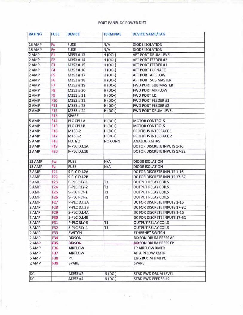
- I
PORT PANEL DC POWER DIST
RATING FUSE DEVICE TERMINAL DEVICE NAME/TAG
15AMP Fx FUSE N/A DIODE ISOLATION 15AMP Fy FUSE N/A DIODE ISOLATION 2AMP F1 M353#13 H (DC+) AFT PORT DRUM LEVEL 2AMP F2 M353# 14 H (DC+) AFT PORT FEEDER #2 2AMP F3 M353 # 15 H (DC+) AFT PORT FEEDER #1 2AMP F4 M353 # 16 H (DC+) AFT PORT FURNACE 2AMP FS M353 # 17 H (DC+) AFT PORT AIRFLOW 2AMP F6 M353# 18 H (DC+) AFT PORT SUB MASTER 2AMP F7 M353 # 19 H (DC+) FWD PORT SUB MASTER 2AMP F8 M353 # 20 H (DC+) FWD PORT AIRFLOW 2AMP F9 M353# 21 H (DC+) FWD PORTLD. 2AMP FlO M353# 22 H (DC+) FWD PORT FEEDER #1 2AMP F11 M353 # 23 H (DC+) FWD PORT FEEDER #2 2AMP F12 M353 # 24 H (DC+) FWD PORT DRUM LEVEL
F13 SPARE SAMP F14 PLCCPU-A H (DC+) MOTOR CONTROLS SAMP F15 PLCCPU-B H (DC+) MOTOR CONTROLS 2AMP F16 M153-2 H (DC+) PROFIBUS INTERFACE 1 2AMP F17 M153-2 H (DC+) PROFIBUS INTERFACE 2 SAMP F18 PLC 1/0 NO CONN ANALOG XMTRS 2AMP F19 P-PLC D.I.1A DC FOR DISCRETE INPUTS 1-16 2AMP F20 P-PLC D.I.1B DC FOR DISCRETE INPUTS 17-32
1SAMP Fw FUSE N/A DIODE ISOLATION 1SAMP Fv FUSE N/A DIODE ISOLATION 2AMP F21 S-PLC D.I.2A DC FOR DISCRETE INPUTS 1-16
-2AMP F22 S-PLC D.l.26 DC FOR DISCRETE INPUTS 17-32 SAMP F23 P-PLC RLY-1 T1 OUTPUT RELAY COILS SAMP F24 P-PLC RLY-2 T1 OUTPUT RELAY COILS SAMP F25 S-PLC RLY-1 T1 OUTPUT RELAY COILS SAMP F26 S-PLC RLY-2 T1 OUTPUT RELAY COILS 2AMP F27 P-PLC D.I.3A - DC FOR DISCRETE INPUTS 1-16 2AMP F28 P-PLC D.I.3B DC FOR DISCRETE INPUTS 17-32 2AMP F29 S-PLC D.I.4A DC FOR DISCRETE INPUTS 1-16
2AMP F30 S-PLC D.l.46 DC FOR DISCRETE INPUTS 17-32 SAMP F31 P-PLC RLY-3 T1 OUTPUT RELAY COILS SAMP F32 S-PLC RLY-4 T1 OUTPUT RELAY COILS 2AMP F33 SWITCH ETHERNET SWITCH 2AMP F34 DIXSON DIXSON DRUM PRESS AP 2AMP F35 DIXSON DIXSON DRUM PRESS FP SAMP F36 AIRFLOW FP AIRFLOW XMTR SAMP F37 AIRFLOW AP AIRFLOW XMTR SAMP F38 PC ENG ROOM HMI PC 2AMP F39 SPARE SPARE
DC- M353#2 N {DC-) STBD FWD DRUM LEVEL DC- M353#4 N (DC-) STBD FWD FEEDER #2

PORT PANEL DC POWER DIST
I k~~ ~~~,,,,- ~ i"~~""~-"-~ --+,-~-~-«----~""" " ~---~ <-"~----~~--~~-f==c::-:c-==~:=c=-----~~---1 G STATION GROUNDS
=-~~-----,----1 G STATION GROUNDS
G STATION GROUNDS
G STATION GROUNDS

RATING FUSE DEVICE TERMINAL DEVICE NAME/TAG
lSAMP Fx FUSE N/A DIODE ISOLATION
lSAMP Fy FUSE N/A DIODE ISOLATION
2AMP Fl M353# 25 H (DC+) AFT PORT DRUM LEVEL
2AMP F2 M353# 26 H (DC+) AFT PORT FEEDER #2
2AMP F3 M353 # 27 H (DC+) AFT PORT FEEDER #1
2AMP F4 DIXSON DIXSON DRUM LEVEL AP
2AMP FS DIXSON DIXSON DRUM LEVEL FP
2AMP F6 DIXSON DIXSON D.A. LEVEL
2AMP F7 DIXSON DIXSON DRUM LEVEL AP
2AMP F8 DIXSON DIXSON DRUM LEVEL FP
2AMP F9 SWITCH H (DC+) ETHERNET SWITCH
SAMP FlO HMIPC H (DC+) ENGINEROOM PC
2AMP Fll SPARE
2AMP F12 SPARE
F13 SPARE
.•.

. ..
U.S. Department o~· Homeland Security
United States Coast Guard
Lake Michigan Carferry
Officer in Charge, Marine Inspection United States Coast Guard Sector Lake Michigan
Attn: Mr. Charles Cart, Senior Chief Engineer 70 1 Maritime Dr. Ludington, MI 49431
Subj: S/S BADGER, O.N. 265156, ABSID 5300348 DRAWING REVIEW, COMBUSTION CONTROL COAL FIRED PROPULSION BOILERS
Ref: (a) Your email request dated February 19,2014 (b) USCG NVIC 10-82, Change 2
Dear Mr. Cart:
2420 S. Lincoln Memorial Drive Milwaukee, WI 53207 Phone: (414) 747-7128 Fax: (414) 747-7883
16711
FEB 2 7 2014
Your request for ABS to review modifications to S/S BADGER, "Propulsion Boiler Combustion Control", on behalfofthe U.S. Coast Guard in accordance with reference (P) is hereby granted. Copies of all ABS reviewed plans and their associated ABS letters shall be provided to Sector Lake Michigan, Milwaukee, WI as required by reference (b).
Sector Lake Michigan will maintain oversight of the project to the degree necessary to fulfill statutory mandates and establish appropriate ABS and USCG liaisons. If the need arises, we will make every effort to be responsive to you, the owners, or ABS in matters of interpretation, policy, or appeal decisions.
Please feel free to contact Richard Baker, Sector Lake Michigan at (414) 747-7127 if you have any questions.
Commander, U. S. Coast Guard Officer in Charge, Marine Inspection By direction
Encl: Email message from Chuck Cart dated February 19, 2014
Copy: ABS Sturgeon Bay w/o encl. Lake Michigan Carferry

)> z (/)
()
0 z :!l 0 m z -i )> r
r--------------------------------------------------------------------------------------------------------------------, I
: I I I I I I I
I : : I I I I I I
: I I I I I I I I I I I I I I I
' I
I
Loop Controll&fl 1thru 12 MODBUS TCP
ETHERNET SWITCH# 2
FI BER RING
STBD Bo ller Contro l Cabinet
Loop Controllers 13 lhru 24 Stemen• PLC 2 CPU a -, MODBUS TCP
1 HMI PC - twoEihernetPorla I I
I PORT Boiler Control Cabinet I I I I I I :
HMI PC. two Ethernet Ports
ETHERNET SWITCH #3
Loop Cont rollers 2:5 thru 27 · MOD BUS TCP
Feectpum p Cont rol Csbln&t
L--------------------------------------------------------------------------------------------------------------------
PRELIMINARY SS BADGER BOILER MODBUS CONTROL NETWORK
0
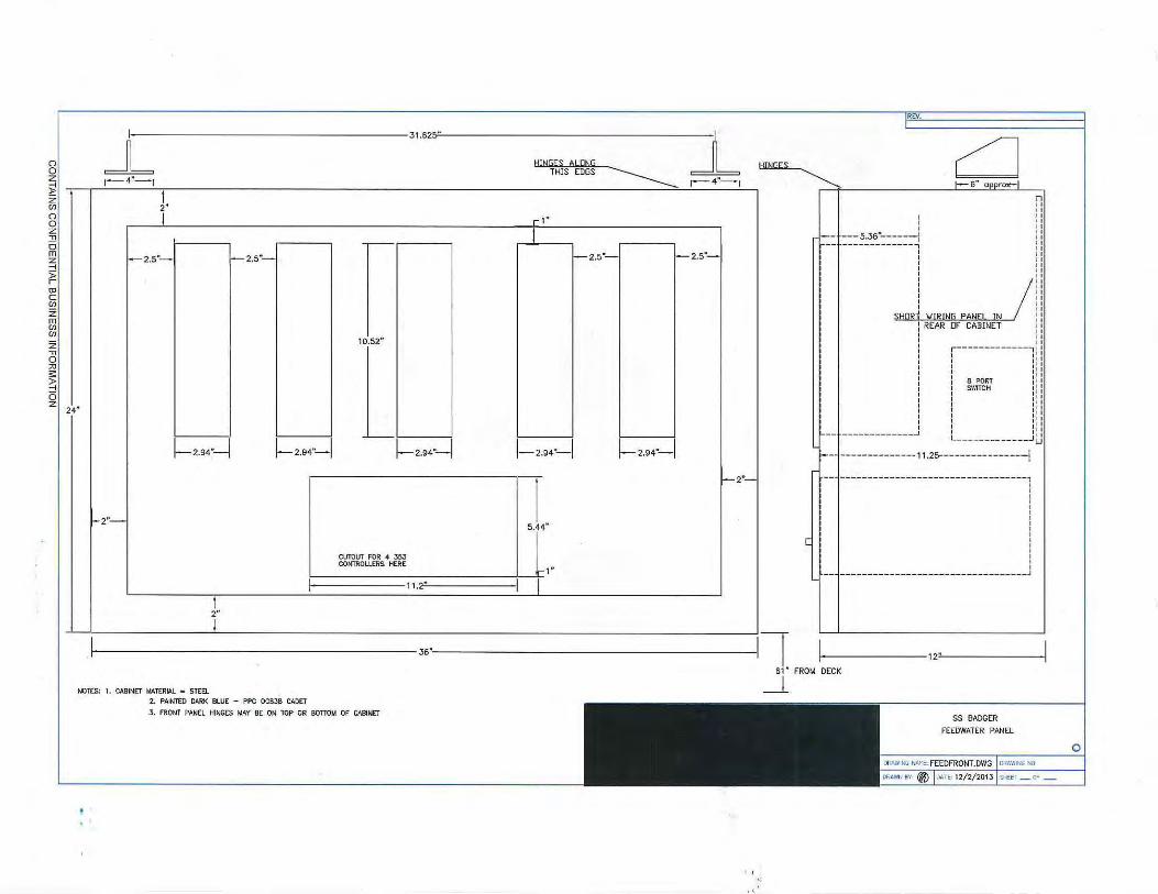
~
24"
~ ,.,. ~:L ~ u 2"
I 1" l
,-,------~
l-2.5"-1 l--2.5"-- f-2.5"- 1 f- 2.5"-
10.52"
~2.94''--1 ~2.94"-1 L__ !---------i
~2.94·-1 1--2.94"--1 ~2.94"-1
1 5.44"
1-2"-
1- 2"-
CUTOUT FOR 4 353 COmROUERS HERE
~----------------~-~1 " r-----------11.2:""
1 2"
I r-------------------------------------------- 36"'--------------------------------------------
[
-,
I - ---5.36"------: -------------, I I I I I
,j ""'"' "'" " / , REAR DF CABINET i I I r------------- , 1
I I I I I I I I I I tl ~ 8 PORT : 1 I SWITCH 1: I I I I I I I I I I I I I I I I II
------------- L _____________ JLJ 1--~-------------1 1.25--- -------------i
----------------------------------, I I I I I I I I I I I I I I I I ____________ _ _______ _ ____ _ ____ _ ___ J
12" --- ----61 " FROM DECK
NOTES' 1. CABINET MATERIAL • STEEL _L
2. PAINTED DARK BLUE - PPC OCBJB CADET
3 . FRONT PANEL HINGES MAY BE ON TOP OR BOTIO~ OF CABINET
·'
0

AFT PORT
DRUM
I BOILER DRUM LEVELS I
FWD PORT
DRUM
D.C. HEATER
LEVEL
D.A.
FWD STBD
DRUM
AFT STBD
DRUM ,--
L___
FEEDWATER PANEL INDICATORS AND CONTROLLERS
FEEDPUMPS & CONDENSATE
D D D D
B ~ ~ B ~~ B ~~ B ~~~ 353 353 353 353 1
I F~s 2 I FP2& 3 I FP27 1 I D.~~ I
LEGEND
25. FEEOPUMP I 2 26. FEEDPUMP H 3 27. FEEDPUMP # 1 28. D.A. & CONDENSER
SS BADG ER FEEDWATER PANEL INDICATORS & CTLRS o

46" 11 68.4mm
5~ r------------------------------------------1371m~m~----------------------------------------
r------------------------~9~o9~---------------------------------~------------------------------------,
I--------------160MM I ~FIELD I./IRE ENTRIES THIS AREA
-1 4.92' 125MM
L
N
~ "
§ ~ ~ ~ ;!; ;!;
2i g 0 0
§ 0 0 ;;: ;;:
~ ;!; ;!;
2i ~ 8 \
NOTE: THIS ARE"A OF CABINET Will HAVE All fiELD WIRING ENTRIES ON TOP ANO 1/AAKED SIDE.
MOUNTED ON SPECIAL DIN RAIL
r 40nM EA MODULE 2 EA CPU ~ 2 CP342-5
4.33" l-110mml
FIELD lORING E~~LT:_:::~~~
~I :i II
r---7.742~ I " I"
:I
7.7425--1
cu~ 'DID D ODD ~ D c a o a o a c
1 0
5.43"
4.92.. g g g g 5.15 .. 125m c a c c 131mm
I ETHERNET I SWITCH ___j_
- , 6.3" - 1 '\_ ON SPECIAL r---160mm "'--MOUNTED DIN RAIL
18.8 • I 5.43· ·r------18.85'"'------ --
OVERSIZED CUTOUTS fOR SIEMENS 353 LOOP CONTROULERS. SIX PER
OVERSIZED CUTOUTS f OR SIEMENS 353 LOOP CONTROLLERS. SIX PER
SLOT. SLOT.
8.25'
~MOUNTING HOLES LOCATED AS /' NECESSARY FOR ATTACHMENT TO CABINET
L-----------------------------------------------------
I I , II I -----.- : ! ~ I I I I I I I
5.43"
1 7.44"
l I I
25.3! I I I I I I I I I I
...J
NOTE: PORT BOILER CABINET INTERNAL WIRING PANEL
19.05mm lr 0 .75"
/3/4' FOLDED EDGES
SS BADGER
PORT BOILER CONTROL CABINET
0

z , 0 ;;o ;;:: ~ 5 z
46.0
~---------------------------------------56.0----------------------------------------l
~-+-4-o------~:~~-~&~~n_~t ---HINGED ALONG THJS EDGE
'Drnl I I
: : 5.12" 7.32" I I 1.30MM
186MM i i I
J
1-225 ..... - - -1 ! I I ! • o :
7.32" 186MM
~0.31'
I I ; .,..., 8"'"' · 8 HOLES
i
0
16.22" 412MM
7.32" 1861.11.1 ! F~m~ U ~~4
: 2.5/ I
SEE PWS 3062/82 DRILLING TE~PLATE
J b~~~~~-~.~~~~~~~0.92' 8 .34 ---1 211.9MM
(23.3MI'l)
HINGED AI ONG THIS EDGE /
~
f---------14" 21· 21· I
STATIONARY PANEL
SS BADGER PORT BOILER CONTROL CABINE!
0

r---------------------------------56.~--------------------------------l
I ..,,.)j t 24.0 I
~ BLD~ING LEFT \ I
I I
: I I I I I I I I I
Jl 2" I
~: I I I I >-'I
ol >:I
§117.4----1-9.7125------IJ
48.0
"1 01
"· IAFTDRUM I
1 I 4.625" !-r 117.5mm (Square)
~ HOLE
t=:t::BB I
(FWD DRUM II \ I . .... __ ,...,.
i!-1-2"
~ " ~ §1
1--l--7.4-1
1 AFT PORT 1 1 7.4
-1
I FWD PORT I H 7·4-l1
I CUTOUTS FOR SIEMENS 353 I CUTOUT FOR SIE"ENS 5.44" LOOP CONTROLLERS. SIX PER 5.44" LOOP CTLRS. M
138.2n m SLOT. 138.2 m
26.3125
24" L 1_~----~=------~
16.8¥ IT 4~~-~7,;m I
~I ·r I L I
II II II II II II II II II II
:,~ If~,l ll---*tl , ,.._\.!_;'\ 1..---..l
r-
m ;!
II II II II
:: Jl" fH--------1 ~
8" z II --- S II ::&
~ ~~~IRI PANEL
II
I!! ru-6.6---1 n--------., II I II I II I II I 1i ________ J II II
~
~
!!~· :: SIEMENS
II II II II
~
n-----------.oJ--11 II II II II II tr------if+-- 1l~25-.-11--1 ' ' 285.8mn;tt---11
'--
NOTE: MOUNTING TABS - BOTH SIDES MAY BE WELDED OR BOLTED TO EXISTING COLUMNS ON VESSEL
48.0
ABOVE OECK (NOT TO SCALE)
1;--REAR ACCESS DOORS
353 CTLRS.
55 BADGER
PORT BOILER CONTROL CABINET
0

I ,.
[AFT . PORT[ [FWD PORT[
D D D D D D D D D D D D
B ~~ B ~~ B ~~ B ~~ B ~~ B ~~ B ~~ B ~~ B ~~ B ~ ~ B ~ ~ g ~~ 353 353 353 353 353 353 353 353 353 353 353 353
DRUM 0 STKR I STKR I. D. F.D. MSTR 1J 14 1 ~ 16 17 18
l MSTR l F.D. l I. D. 11 STKR 10 STKRI DRUM J 19 20 21 22 2J 24
- ---·- - · - - ~
LEGEND
13. AFT PORT DRUM LEVEL 14. AFT PORT OTBD FEEDER 15. AFT PORT INBD FEEDER 16. AFT PORT I.D. FAN 17. AFT PORT F.D. FAN & OFA 18. AFT PORT SUB MASTER 19. FWD PORT SUB- MASTER 20. FWD PORT F.D. FAN & OFA 21. FWD PORT I.D. FAN
PORT CABINET COMBUSTION CONTROLS LAYOUT 22. FWD PORT INBD FEEDER 23. FWD PORT OTBD FEEDER 24. FWD PORT DRUM LEVEL
SS BADGER PORT BOILER PANEL 353 CONTROLLERS 0
0 u

1-----------------------,~jl mm 19.05mm . lr 0.75"
46" 1168.4mm
- ----- -- - - -- -- --------- ---------------------,1 lr--- ---------- - - - ---- - ------------- ~FIELD IJ IRE ENTRIES THIS AREA
1 0
1-4.33" 1 11omml
a o a o ~ D D 0 0 0 Q D D g ~ g g 5.15 .. o o o o 131mm
ETHERNET __j_ SWITCH
NOTE: THIS AR£A OF CABINET WILL f'AVE ALL FIELD WIRING ENTRIES ON TOP AND MARKED SIDE.
Elf! D lORING ENTRIES T:~ ;:::
~/£.f'.olJlo_mu_~ I I I I
17.742~
5.43" 16.8 • ,5.43" 18.8. 15.43"
OVERSIZED CUTOUTS FOR SIEMENS 3, 3 LOOP CONTROLLERS. SIX PER SLOT.
/ NECESSARY FOR ATTACHMENT TO CABINET
I B.2S'
1 7.44"
OVERSIZED CUTOUTS FOR SIEMENS JSJ LOOP CONTROLLERS. SIX PER SLOT.
l
~MOUNTING HOLES LOCATED AS l L ------ -- - ---------= ------------ ----- -- -----------""""""""" ----
_____ ]l NOlt: PORT BOILER CABINET INTERNAL WIRING PANEL
/3/4' FOLDED EDGES
SS BADGER STBD BOILER CONTROL CABINET
0

56.
HINGED ALONG THIS EDGE ~ 7L 186MM
7.32" 186MM
HINGED ALONG THIS EDGE
~ 7 . .32"
17MM
48.0
21' 21'
,------~~~~-~6~~~~
I Dr-I I-225MM ___ ,
0
0.31' BMM I
8 HOLES 0 1 I I I I I
I I ~t~ 1-,';;:..,--1 kl:r ------~~;:.-= j
211.9MM
14"
STATIONARY PANEL
~ 5.1
1.30
16.: 412
In
~
2" MM
2" MM
SEE PWS 3062/82 ORILUNC Tt" PlATt
[\...._ 0.92' (23.3MM)
SS BADGER
STBD BOILER CONTROL CABINET
0
' ,,

0 z
48.0
56. I
r- I I tr--1 I I I
LJ -------4• FAN I I I
BLD'.'lNG RIGHT I I
I I I I I I I I I I
2" I I I I I
~: I I .. , I .,, I
i!-7.4---9.7125--1
4.n' Dla :---1 1.688 I!-
z: 0 HOLE !';-' ... , . . ~ : / \ I AFT ORUt.q : \ .375
I I ' !FWD DRUMI ~ I \ ' ' -:u_ : ' ... __ ...... ' , ~
.... __ ... . I ~-~ 4.625" - 3.3751- i I I 117.5mm (Square)
,7.4-1 1-f-- 7.4-1 I FWD STBD I I AFT STBD I I- 7.4--1 I I I
I I I
CUTOUTS FOR SIEMENS J5J 26.3 125 I
CUTOUT FOR SIEMENS I 5.44" LOOP COifrROLLERS. SIX PER 5.44" LOOP CTLRS. I
138.2r m SLOT. 136.2n m I I
j_ l_ I I I
24"
II 16.85" I I
16.8~ 427.9mm I I I I
I T;· I I I I I
'--- r--
NOTE: IAOUNllNG TABS TO EXISTING COUJUNS
48.0 ABOVE DECK (NOT TO SCALE)
24. I
2"
II II II II II II II II II
il II II
I ,(\", I
: r~~:>J: 1' ... \l./ I L.---...1
r-
~
:: Jl" II z
fH--1 • i 8--- ::>
I' o
!L/---"'IRI ,.PANEL
II
W;=':
~~~~ II -, II I II I II I II I 1t ________ J II II II
~
~ 5
i{REAR ACCESS
II II
II "' ~SIEMENS 353 CTLRS.
'I / ~1----L __ I I -II II II
" " t~-------- L 'i H+---- 11.25.- --" ·· 285.8mm
BOTH SIDES W.Y BE wru>ED OR BOLTED VESSEL
L..
SS BADGER
STBD BOILER CONTROL CABINET
0
·A

IFWD STBbl I AFT STBD I
D D D D D D D D D D D D
B ~~ B ~~ B ~~ B ~~ B ~~ B ~~ B ~~ B ~~ B ~~ B ~~ B ~~ B ~ ~ 353 353 353 353 353 353 353 353 353 353 353 353
I DR1UM 10 ;>TKR I I ~TKR I ~D . I F;D. _ ] MS6T~ I 1 MSTR 1 F.D. 1 I. D. ~~- STKR jo - sT5 R .DR.~M 1 e 9 10 11 12
- -- -
LEGEND
1. FWD STBD DRUM LEVEL 2. FWD STBD OTBD FEEDER 3. FWD STBD INBD FEEDER 4. FWD STBD I. D. FAN 5. FWD STBD F.D. FAN & OFA
STBD CABINET COMBUSTION CONTROLS LAYOUT 6. FWD STBD SUB MASTER 7. AFT STBD SUB-MASTER AND
PLANT MASTER 8. AFT STBD F.D. FAN & OFA 9. AFT STBD I.D. FAN
1 0. AFT STBD INBD FEEDER 11 . AFT STBD OTBD FEEDER 12. AFT STBD DRUM LEVEL
SS BADGER STBD BOILER PANEL 353 CONTROLLERS
CJ'J => CXl -' <(
t= z w 0 u:: z 0 (.)
CJ'J z ~ z 0
I (.)
0

From: Sent: Friday, March 07, 2014 1:15PM To: 'Marine Shop' Cc: Chuck Leonard Subject: FW: SS Badger Boiler Combustion Control Submittals 2 of 2
Chuck You may want to ask Mr. Leonard to copy all of the attachments on a CD or Memory Stick for a print shop to make prints .
• From: Sent: To: [email protected]; [email protected] Subject: FW: SS Badger Boiler Combustion Control Submittals 2 of 2
Dear Henry and M ohammad,
This is my second email wit h submitta ls at tach ed.
1
CONTAINS CONFIDENTIAL BUSINESS INFORMATION

.. I
Please find the above SS Badger Boiler Combustion Control project submittals attachments for your review. Our cover letter is attached giving an overview of the project and a list of Enclosures for you r review. The installation of the new systems is now being performed aboard the SS Badger in Ludington, Michigan during the vessels winter lay-up. The project is to be completed in April to begin testing, dock trials and sea trials to be ready for the first voyage on May 16th_ In other words we need to have this review treated as urgent. We had the Hindle Power Inc. 24 VDC power supply system that we are using for redundant power to our systems reviewed and factory tested and approved by ABS in January. ABS Project No. 3176956, Task No. 1134456. Chuck Cart the SS Badger's Senior Chief Engineer has had the local USCG and ABS office involved in the project. We will send you a forma l purchase order today. The PO number will be BAD030714. Please fee l free to give me a call or emai l me w ith any questions.
Respectfully
•
2 CONTAINS CONFIDENTIAL BUSINESS INFORMATION
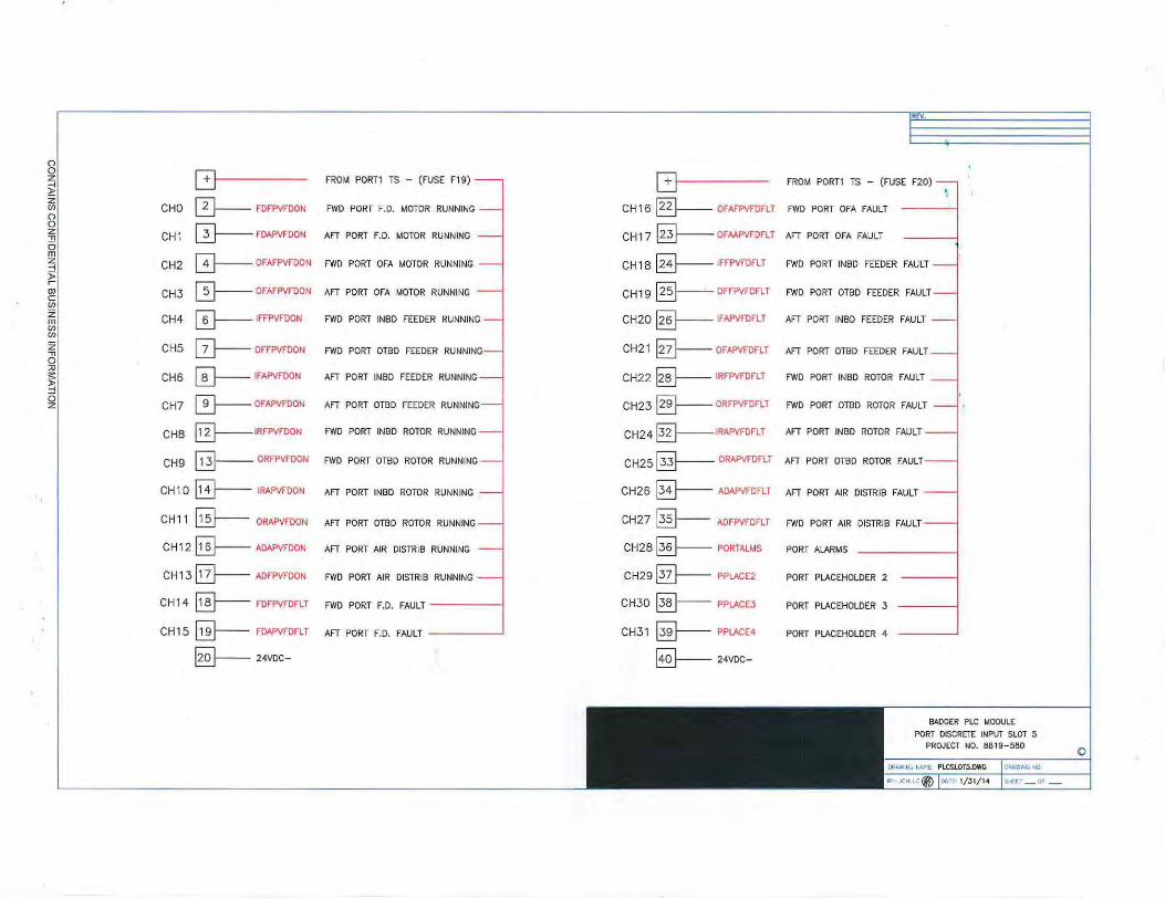
() 0
G z FROM PORT1 TS - (FUSE F19) ~ z 0--- FOFPVFOON rn CHO FWD PORT F.O. MOTOR RUNNING ()
0 ~FDAPVFDON z
CH1 AFT PORT F.D. MOTOR RUNNING .., 0 m 0-- OFAFPVFDON z CH2 FWD PORT OFA MOTOR RUNNING ::j )> r IT}--OFAFPVFDON tD CH3 AFT PORT OFA MOTOR RUNNING c rn z CH4 0-- IFFPVFDON FWD PORT INBD FEEDER RUNNING m rn rn z CH5 0--- OFFPVFOON FWD PORT OTBD FEEDER RUNNING .., 0 :u 0--- IFAPVFOON s: CHS AFT PORT INBD FEEDER RUNNING )> -i 0
CH7 0-OFAPVFDON AFT PORT OTBD FEEDER RUNNING z
CHB ~IRFPVFDON FWD PORT INBD ROTOR RUNNING
CH9 §--ORFPVFDON FWD PORT OTBD ROTOR RUNNING
CH1 0 ~ IRAPVFOON AFT PORT INBD ROTOR RUNNING .
CH1 1 ~ ORAPVFOON AFT PORT OTBD ROTOR RUNNING
CH 12 ~ ADAPVFDON AFT PORT AIR DISTRIB RUNNING
CH 13 0---- ADFPVFOON FWD PORT AIR DISTRIB RUNNING
CH 14 §---- FDFPVFDFLT FWD PORT F.D. FAULT
CH 15 @--- FDAPVFDFLT AFT PORT F.D. FAULT
~24VOC-
G CH16 ~ OFAFPVFOFLT
CH17 ~OFMPVFDFLT
CH18 0---- IFFPVFDFLT
CH19 §--OFFPVFDFLT
CH20 §-- IFAPVFOFLT
CH21 [32)- OFAPVFDFLT
CH22 @- IRFPVFOFU
CH23 ~ORFPVFDFLT
CH24 0----IRAPVFDFLT
CH25 ~ ORAPVFDFLT
CH26 ~ ADAPVFOFLT
CH27 ~ ADFPVFDFLT
CH28 ~ PORTALMS
CH29 0---- PPLACE2
CH30 ~ PPLACEJ
CH31 @----- PPLACE4
~24VDC-
- -~-------~
REV.
E FROM PORT1 TS - (FUSE F20)
FWD PORT OFA FAULT
AFT PORT OFA FAULT
FWD PORT INBD FEEDER FAULT
FWD PORT OTBD FEEDER FAULT
AFT PORT INBD FEEDER FAULT
AFT PORT OTBD FEEDER FAULT
FWD PORT INBD ROTOR FAULT
FWD PORT OTBD ROTOR FAULT
AFT PORT INBD ROTOR FAULT
AFT PORT OTBD ROTOR FAULT
AFT PORT AIR DISTRIB FAULT
FWD PORT AIR DISTRIB FAULT
PORT ALARMS
PORT PLACEHOLDER 2
PORT PLACEHOLDER 3
PORT PLACEHOLDER 4
BADGER PLC ~ODULE
PORT DISCRETE INPliT SLOT 5 PROJECT NO. 8819-560
MAWIN~ ~0.
srtrrr_ or _
0

PORT Dl # 1 A FIELD DEVICE DC+
I FUSE F17 CHL 1 & 2
'- CHL 3 & 4
- CHL 5 & 6
- CHL 7 & 8
- CHL 9 & 10
- CHL 11 & 12
- CHL 13 & 14
- CHL 15 & 16
PORT 01 # 18 FIELD DEVICE DC+
j rusE F18 CHL 17 & 18
r- CHL 19 & 20
r- CHL 21 & 22
r- CHL 23 & 24
I- CHL 25 & 26
I- CHL 27 & 28
r- CHL 29 & 30
~ CHL 31 & 32
2
3
4
5
6
7
8
9
10
11
12
13
14
15
16
PLC DISCRETE INPUT FIELD DEVICE DC+ TERMINALS
STBO Dl I2A FIELD DEVICE DC+
I FUSE F19 CHL 1 & 2
- CHL 3 & 4
- CHL 5 & 6
- CHL 7 & 8
r- CHL 9 & 10
r- CHL 11 & 12
I- CHL13&14
'---- CHL 15 & 16
STBD Dl #28 FIELD DEVICE DC+
! rusE F20 CHL 17 & 18
- CHL 19 & 20
- CHL 21 & 22
- CHL 23 & 24
- CHL 25 & 26
- CHL 27 & 28
- CHL 29 & 30
- CHL 31 & 32 --
2
3
4
5
6
7
8
9
10
11
12
13
14
15
16
PORT Dl #3A FIELD DEVICE DC+
j FUSE F25 CHL 1 & 2
- CHL 3 & 4
- CHL 5 & 6
I- CHL 7 & 8
r- CHL 9 & 10
r- CHL 11 & 12
I- CHL 13 & 14
'---- CHL 15 & 16
PORT 01 #38 FIELD DEVICE DC+
j rusE F26 CHL17& 18
r- CHL 19 & 20
r- CHL 21 & 22
r- CHL 23 & 24
f-- CHL 25 & 26
- CHL 27 & 28
- CHL 29 & 30
- CHL 31 & 32
TERMINAL STRIPS TO BE LOCATED ADJACENT TO PLC 1/0
2
3
4
5
6
7
B
9
10
11
12
13
14
15
16
STBD Dl #4A FIELD DEVICE DC+
I FUSE F27 CHL 1 & 2
f--. CHL 3 & 4
f-- CHL 5 & 6
f--. CHL 7 & B
f-- CHL 9 & 1D
- CHL 11 &: 12
- CHL 13 &: 14
- CHL 15 & 16
STBD Dl #48 FIELD DEVICE DC+
j rusE F"28 CHL 17 & 18
I- CHL 19 & 20
r- CHL 21 &: 22
r- CHL 23 & 24
r- CHL 25 & 26
f-- CHL 27 & 28
f--. CHL 29 &: 30
'-- CHL 31 & 32
2
3
4
5
6
7
B
9
10
11
12
13
14
15
16
BADGER BOILER PANEL WIRING PORT PANEL D.l. POWER TERMINALS
0

F14 F15
CPU - A
315-2 PN/DP
r
CP342 -5
A
I
PORT BOILER CABINET - MAIN PLC LAYOUT
CPU - B
315-2 PN/DP
CP342 - 5
B
SLOT 4 SLOT 5 SLOT 6 SLOT 7 SLOT 8 SLOT 9 SLOT 1 0 SLOT 11 SLOT 12 SLOT 13 SLOT 14
IM1~ A.l. D.l. D.O. D.O. D.l. D.O. D.O. D. l. D.l. D.O. D.O. I EMPTY -2 - 2 8 CHL. 32 CHL. 8 CHL. 8 CHL. 32 CHL. 8 CHL. 8 CHL. 32 CHL. 32 CHL. 8 CHL. 8 CHL.
/ RELAYS RELAYS RELAYS RELAYS RELAYS RELAYS
A I B Il l I PORT PORT PORT STBD STBD STBD PORT STBD PORT STBD D.l. #1 D. O. #1 D. O. #2 D. l. # 1 D.O. # 1 D.O. #2 D.l. #2 D.l . #2 D.O. #3 D.O. #3
Pf f1 1CV ~ I ~~~f1 1 1 ~ I l r2f 1 ~~ I r2f&p l I r2f1 I r2f
F16 _9=1 _g=J I L F23 ~ F24 F25 _j F26_j F31 =._] F3;-=J
DC- (COMMON)!
F17
NOTE: DC+ SUPPLY FOR DISCRETE FIELD INPUTS SHOWN ON PLC 0.1. POWER TERMINALS DRAWING.
BADGER PLC OVERVIEW
..
0

(")
0
G z ~ z 0----(/) CHO APIBRTRSW (")
0
0-----z CH1 APOBRTRSW :!! 0 m
0-z CH2 FPIBRTRSW ~ ;; r @-----ll> CH3 FPOBRTRSW c: (/)
z CH4 0------m (/) (/)
z CHS [2}----n 0 ;o
0------~ CH6 ~
0 z CH7 0------
CH8 0-CH9 §----CH100--
CH1 1 @---CH12~
CH130-
CH14§--
CH15 0----I3Q}-- 24VDC-
FROM PORT1 TS - (FUSE F27) - --- - -, CABLE IDENT
AFT PORT INBD ROTOR TACH SW. K2600 PAIR H 1
AFT PORT OTBD ROTOR TACH SW. K2600 PAIR 82
FWD PORT INBD ROTOR TACH SW. K2601 PAIR # 1
FWD PORT OTBD ROTOR TACH SW. K260 1 PAIR /J2
REV.
G FROM PORT1 TS - (FUSE F28)----, CABLE IOENT
CH160-
CH17~
CH18~
CH19~ CH20 §----CH21 [ill-CH22 §----CH23~
CH24§]-
CH25~ CH26~
CH27~ .
CH28~
CH29§}-
CH30 §---CH31~
~24VDC-
BADGER PLC MODULE PORT DISCRETE INPIJT SLOT 11
DAA.W:N~ hiJ".
5-o£(- _ o.-- -
0
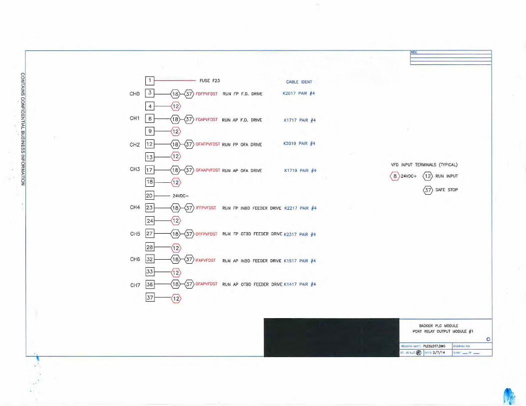
~ FUSE F23 CABLE IDENT
CHO 0-----@--® FDFPVf"DST RUN FP F.D. DRIVE K2017 PAIR #4
GJ---@ CH 1 ~ f"DAPVFDST RUN AP F.D. DRIVE K1 717 PAIR #4
0-@ CH2 ~ OFAFPVFDST RUN FP OFA DRIVE K2019 PAIR #4
~@ CH3 0--@--® OFAAPVFDST RUN AP OFA DRIVE K1719 PAIR f4
§--@ ~ 24VDC-
CH4 ~ IFFPVFDST RUN FP INBD FEEDER DRIVE K2217 PAIR #4
~ CH5 B-------@--® oFFPVFDST RUN FP OTBD FEEDER DRIVE K2317 PAIR #4
@---@ CH6 §--@-®IFAPVFDST RUN AP INBD FEEDER DRIVE K1517 PAIR #4
§--@ CH7 ~@-®oFAPVFDST RUN AP OTBD FEEDER DRIVE K1417 PAIR 64
§---@
VFD INPUT TERMINALS (TYPICAL)
® 24VDC+ @RUN INPUT
®SAFE STOP
BADGER PLC MODULE PORT RELAY OUTPUT MODULE # 1
0
. 0' 'df '

'
REV.
(")
QJ 0 FUSE F23 CABLE IDENT z
~ ~IRFPVFDST RUN FP INBD ROTOR DRIVE K2219 PAIR #4 z CHO (Jl
(")
CD--@ 0 z :!! 0
0--®--® ORFPVFDST RUN FP OTBD ROTOR DRIVE K2319 PAIR #4 m CH1 z -i )>
0---@ ,.... (D
c (Jl
~IRAPVFDST RUN AP INBD ROTOR DRIVE K15 19 PAIR #4 z CH2 m (Jl
~@ (Jl
z , VFD INPUT TERMINALS (lYPICAL) 0
0-@--® ORAPVFDST RUN AP OTBD ROTOR DRIVE K1419 PAIR #4 ::0 CH3
® 24VDC+ @RUN INPUT s: )> -i
~ 0
®SAFE STOP
z
~24VDC-
CH4 ~ADAPVFDST RUN AP AIR DISTRIB DRIVE K 1533 PAIR /14
~ CHS ~ADFPVFDST RUN FP AIR DISTRIB DRIVE K2233 PAIR 64
~@ CH6 §----@-® PORTALARM PORT BOILER ALARM OUT
0-----@ CH7 0----®--® POUTPLACE1 PLACEHOLDER 1
~@
BADGER PLC MODULE
PORT RELAY OUTPUT MODULE 62
0 o:uw·t-t.; NO:
~t: r _ Cf _

()
~ ~ z en ()
0 z "T1 5 m
l ~ - ~
' •OJ c ~ z m en en z "T1 0 ::0
~ 0 z
[2] FUSE F26 CABLE IDENT
CHO 0-------®-® IRFSVFDST RUN FS INBD ROTOR DRIVE K0319 PAIR #4
@----@ CH 1 0-------®-® ORFSVFDST RUN FS OTBD ROTOR DRIVE KD219 PAIR #4
0------@ CH2 §---@--® IRASVFDST RUN AS INBD ROTOR DRIVE K1019 PAIR #4
~@ CH3 0-------@-® ORASVFDST RUN AS OTBD ROTOR DRIVE K1119 PAIR #4
[§-------@ g_ 24VDC-
CH4 0--@-®ADASVFDST RUN AS AIR DISTRIB DRIVE K1D33 PAIR #4
~ CH5 0--@--®ADFSVFDST RUN FS AIR DISTRIB DRIVE KD333 PAIR #4
~@ CH6 0-@--®sTBDALARM STBD BOILER ALARM OUT
El--@ CHl §--@-®soUTPLACE1 STBD PLACEHOLDER 1
~@
liD/.
VFD INPUT TERMINALS (lYPICAL)
® 24VDC+ @ RUN INPUT
®SAFE STOP
BADGER PLC MODULE
STBO RELAY OUTPUT MODULE 62
l)lo(AW~N-..i ,.,0,
~(T _ OF -
0
. '~ ~
~ ... ,
·,
,,

G FROM PORT1 TS - ( FUSE F27) - - -----,
CHO CD- AOIBRTRSW AFT STBO INBO ROTOR TACH SW.
.., CH 1 0----- AOOBRTRSW
0 AFT STBO OTBO ROTOR TACH SW.
m 0----z CH2 FSIBRTRSW -l 5> r 0-----0::1 CH3 FSOBRTRSW c
FWD STBO INBD ROTOR TACH SW.
FWD STBO OTBO ROTOR TACH SW.
(fJ
z CH4 0-m (fJ (fJ
z CH5 0--CH6 0-CH7 0-----CHB §--CH9 §---
CH10 0--
CH11@--
CH12@----
CH13@}-
CH14 ffi-CH15@--
~24VDC-
CABLE !DENT
K2500 PAIR # 1
K2500 PAIR #2
K25D1 PAIR #1
K2501 PAIR #2
G FROM PORT1 TS - (FUSE F2B)--~ CABLE !DENT
CH16 0--CH17~
CH18~
CH19~ CH20~
CH21[3B
CH22~
CH23~
CH24§}
CH25~
CH26 0-
CH27~
CH280--
CH29~
CH30~
CH31~
~24VDC-
BADGER PLC MODULE
STSD DISCRETE INPUT SLOT 12
),
' ;
0

' ,
G FROM STBD1 TS - (FUSE F21)
CHO 0-------<:D FDFSVFDON FWD STBD F.D. MOTOR RUNNING
CH1 0--------<:D FDASVFDON AFT STBD F.D. MOTOR RUNNING
CH2 0-------0 OFAFSVFDON FWD STBD OFA MOTOR RUNNING
CH3 0----® OFAFSVFDON AFT STBD OFA MOTOR RUNNING
CH4 ~ IFFSVFDON FWD STBD INBD FEEDER RUNNING
CHS ~ OFFSVFDON FWD STBD OTBD FEEDER RUNNING
CH6 0----0 IFASVFDON AFT STBD INBD FEEDER RUNNING
CH7 0----® OFASVFDON AFT STBD OTBD FEEDER RUNNING
CH8 ~ IRFSVFDON FWD STBD INBD ROTOR RUNNING
CH9 @)-----® ORFSVFDON FWD STBD OTBD ROTOR RUNNING
CH10~ IRASVFDON AFT STBD INBD ROTOR RUNNING
CH1 1 ~ ORASVFDON AFT STBD OTBD ROTOR RUNNING
CH 12 @------0 ADASVFDON AFT STBD AIR DISTRIB RUNNING
CH13 0---0 ADFSVFDON FWD STBD AIR DISTRIB RUNNING
CH14 0-----0 FDFSVFDFLT FWD STBD F.D. FAULT
CH 15 @-------0 FDASVFDFLT AFT STBD F.D. FAULT
B--- 24VDC-
VFDS' RELAY OUTPUTS (TYPICAL)
R1 0----tf--0---1 ~ R2 ®---*--@-1 r--®
CABLE IDENT
K0517 PAIR #2
K0817 PAIR #2
K0519 PAIR #2
KD819 PAIR #2
K0317 PAIR #2
K0217 PAIR #2
K1017 PAIR #2
K1117 PAIR #2
K0319 PAIR #2
K0219 PAIR #2
K1019 PAIR #2
K1 1 19 PAIR #2
K 1033 PAIR #2
K0333 PAIR #2
K0517 PAIR #3
K0817 PAIR #3
G FROM STBD1 TS - (FUSE F22)----, CABLE IDENT
CH16 ~ OFAFSVFDFLT
CH17 0-@oFMSVFDFLT
CH 18 ~IFFSVFDFLT
CH19 §---@ oFFSVFDFLT
CH20 §---------® IFASVFDFLT
CH21 B-@o FASVFDFLT
CH22 §--------®IRFSVFDFLT
CH23 ~ORFSVFDFLT
CH24 §-®IRASVFDFLT
CH25 §-------® ORASVFDFLT
CH26 0-------® ADASVFDFLT
CH27 ~ ADFSVFDFLT
CH28 ~ PORTALMS
CH29 0---- PPLACE2
CH30 ~ PPLACE3
CH31 ~ PPLACE4
~24VDC-
FWD STBO OFA FAULT K0519 PAIR #3
AFT STBD OFA FAULT K0819 PAIR #3
FWD STBD INBD FEEDER FAULT KD317 PAIR #3
FWD STBD OTBD FEEDER FAULT KD217 PAIR #3
AFT STBD INBD FEEDER FAULT K1D17 PAIR #3
AFT STBD OTBD FEEDER FAULT K 111 7 PAIR #3
FWD STBD INBD ROTOR FAULT K0319 PAIR #3
FWD STBD OTBD ROTOR FAULT KD219 PAIR #3
AFT STBD INBD ROTOR FAULT K1019 PAIR #3
AFT STBD OTBD ROTOR FAULT K1119 PAIR #3
AFT STBD AIR DISTRIB FAULT K 1033 PAIR #3
FWD STBD AIR DISTRIB FAULT K0333 PAIR #3
STBD ALARMS
STBD PLACEHOLDER 2
STBD PLACEHOLDER 3
STBD PLACEHOLDER 4
BADGER PLC MODULE
STBD DISCRETE INPUT SLOT 6
0
• '·

QJ FUSE F25 CABLE IDENT
CHO 0--@--® FDFSVFDST RUN FS F.D. DRIVE K0517 PAIR 14
GJ---@ CH1 0-@--® FDASVFDST RUN AS F.D. DRIVE K0817 PAIR #4
0----@ CH2 ~ OFAFSVFDST RUN FS OFA DRIVE K0519 PAIR #4
~@ VFD INPUT TER~INALS (TYPICAL)
CH3 G21-@-® OFMSVFDST RUN AS OFA DRIVE K0819 PAIR #4
® 24VDC+ @RUN INPUT
@I ~ ®SAFE STOP @---- 24VDC-
CH4 ~IFFSVFOST RUN FS INBD FEEDER DRIVE K0317 PAIR #4
§----@ CHS ~OFFSVFDST RUN FS OTBD FEEDER DRIVE K0217 PAIR #4
@--@
CH6 ~IFASVFDST RUN AS INBD FEEDER DRIVE K1017 PAIR 64
§--@ CH7 §-@-®aFASVFDST RUN AS OTBD FEEDER DRIVE K1117 PAIR //4
~@
BADGER PLC MODULE
STBD RELAY OLITPUT MODULE # 1
0

VFD TAGNAMES
TAGNAM E DESCRIPTOR
FPFDFAN FWD PORT F.D. FAN
APFDFAN AFT PORT F.D. FAN
FPOFA FWD PORT OVERFIRE AIR
A PO FA AFT PORT OVERFIRE AIR
FPIBFEDR FWD PORT INBD FEEDER
FPOBFEDR FWD PORT OTBD FEEDER
APIBFEDR AFT PORT INBD FEEDER
APOBFEDR AFT PORT OTBD FEEDER
FPIBROTR FWD PORT INBD ROTOR
FPOBROTR FWD PORT OTBD ROTOR
APIBROTR AFT PORT INBD ROTOR
APOBROTR AFT PORT OTBD ROTOR
APAIRDIST AFT PORT AIR DISTRIB
FPAIRDIST FWD PORT AIR DISTRIB
FSFDFAN FWD STBD F.D. FAN
ASFDFAN AFTSTBD F.D. FAN
FSOFA FWD STBD OVERFIRE AIR
ASOFA AFT STBD OVERFIRE AIR
FSIBFEDR FWD STBD INBOD FEEDER
FSOBFEDR FWD STBD OTBD FEEDER
ASIBFEDR AFT STBD INBD FEEDER
ASOBFEDR AFT STBD OTBD FEEDER
FSIBROf R FWD STBD INBD ROTOR
FSOBROTR i:WD STBD ()TBD ROTOR
ASIBROTR AFT STBD INBD ROTOR
ASOBROTR AFT STBD OTBD ROTOR
ASAIROIST AFT STBD AIR DISTRIB
FSAIRDIST FWD STBD AIR DISTRIB

r. --------- ., r. ----- ---- ., ro --------- ---- ., ro ---- ---------I I I
- 4 .01' 1- ! I I I I ,- I I I I
~
+ T I I I -+ ---- + I ----------- -- .------~
I I r n I I I 9.37" 9 .37" I I
r·Ol' C ~ I
~ C/L 1 f- C/L -I I I I MTG I MTG HOLES ~ TG ,HOLES I I I
11( 1·. I I I I I I
L___.J I I I I I
10 1- p I
5 HP I I I I I
--------- ~ I -~- ---- · ~ - I -----------__ L _.:. _____
' .... - --- I - I L I .L I I
I I
r; --------- ., I I
I I I I I I I 20 HP I 20 HP I I r. - -------- ., I I
I -1 401 '. 1 : I I I I I .------ I
Lo -------------~J I I I -+ + -------------I ----
I I
~ I I I i -1 4.01' I
- I C/L
I I MTG I I
'-- I I I I
--~--~£:. J I I 1h n
I -~: ---- ·l -I F=-I L..· - - --- --
'---
VIEW FROM REAR OF VFD MOUNTING RACK ·
o1
( f-f D ~
15.75"
I I
I I
! , ANGLE SIDE f I VIE\/ I
IIELDED I I I
DJ
t"" v-
I-"
[7 r-_,.
MOUNTING BRACKETS F"DR 20, 10 AND 5 HP MODELS
SS BAOGER PORT VfO BRAKE RESISTOR MOUNTING
•
0

2
I I I I 'I I I I I I I I I I I I I I I r 1 1 1 1 1 1 1 1 1 I I I I I I I I I I I I I : : I : I : : : I : : I I ' ' ' ,_ L-so.e ' ' ' ' ' ' j.+-945'" ' j : ! I ' : i -i I ! ! ! ! i i I I . :
• rl · : 0.37"J 0
'ri APOFA :· r- A-P~~R~~-,, · • APINFEDR1 · ·-~~~~F~~R1 -FPiN-FEOR -APtisF;.E-D~Il·· +---- -;-1 I I .53-I I I I
APFDFAN I FPFDFAN ! 16B--J I ! ! 1- .06" I I : I I I I I I I ~ ,,.. , : l 16.5
I . i i 16.9" ~ · ~, i l I I I I I 1 . 06~
6.97" :-:..:.- ! ~~~ ! i 5 HP I 2 HP 2 HP ! 2 HP 2 HP
I ! I i 10 HP i • ---------4, .t---------4, .l---------J. --------- -- ------ . +----+
4"
! I t __ ----·.--J }-- .. : I- ~ ~ ... --: : .. ~ t-- ... } I I I : I I : : : : : : : 4.9~
1
I I .! I I - 1 - m.50B3 I I I I I I I
2"
I I 4 92"1 25 I I I I I I I I I I 1 20 H9 20 HP ! . ·1 i · ·-;P~~~~~--· . ~P~N~~TR-r ·-~~~sR~~i ··--F'Pit:iRorR1 ··-;;;oi3'Ror'R1
_L I 0.2p1 -FPOFA-- : I : I or ' 1o 0 _t_ to : : :
~12.12tr---+l ... t-l - 188--- i : : I l ! ! 'Y 16,5
i 10 HP l-~--~~--' . •-~--~~-J --~--~:-1. . -~--~~--' . .l-~--~~-J -+----....!....
54"
I I I I I . I I' I I .. I I • I ,.- a:. 1 " r- -~ 1 4 .4 r , ,, 1 I .6, 1 I I I I I I I I I I I 0 35"' I I I I I I I I I : __ :_ ______ l o : : : : : l : : I I I I I I I I I I I I
I W- 'I I I I I I I I I I I I .. I I I I I I I I I I I I I 9.53 ---,- I I I I I I I I I I I I I I I I I I I I : : : : I : : I : : I I I I I I I I I I I I I I
NOTES: 1. ALL DIMENSIONS IN INCHES 2. 2 HP AN D 5 HP UNITS ARE THE SAME SIZE 3 . PLEAS E IDENTIFY BACKING PLATES IN SHIPMENT OF
DRIVES - USE PLATES AS TEMPLATES TO CONFIRM/ ASSIST WITH FRAME ASSY AND MOUNTING HOLE LOCATIONS.
SS BADGER
PORT VFD RAC K lAYOUT
0

0 0 z :!! 0 m z ~ j: r
MOUNTING BRACKETS FOR 20, 10 AND 5 HP MODELS
15.75"
r4-------------r: r~-------------~o, I I I ! I
~ y.:-----l--~11 ! I ~ ~---------1 11 ! I : ll ----1+- i i l IT ~ C/L 1- C/L - I ~ .0 1 ' I I l II
l I I l ___ I
I :: - l
9.37" k11 9.J7" I . j ~ I I
MTG HOl- MTG HOLES I C/L J 1 1-- j i J.
1
J MTG J J J
I' ' I : : : : ______ _1 __ , ! ----- - -- ! -+ ----~~- I [., --------- ..:
D I! I I I
L~-------------~j
--~ -- \J
'----D r.T----- ----1".,
L~-------------~j t1-tJ1::::+r1-~~+,rf~=J~llJ
L__
l !JfBtt ~ -- --- -- u
'----
VIEW FROM REAR OF VFD MOUNTING RACK
SS BAOGER STBD VFD BRAKE RESISTOR MOUNTING
0

' I I I I I I
I I I I I I I I I I I I I I I I I I I I I I I I I I I I
I tt--9.45"1 1 I I I I I I I I I I I I I I I I I I I I
;F~:::---. --------- . r-------- 1
. ,----- - -1 . I I I
I I I I
6.54" • e.r lfJ l I I
I I I
I I I
2 HP 2 HP HP I
12 I I
------- - b·"" . ~--~-~-- . 0 ~---------" . .l---------1. '- .4 I I. 4 I f .< I I I
' I ' ' I r I k92" I I I I I I I I I I I I I I
0.50ih --I I I I I I I I I I I I I I
4
. . "r---------, . · ~----------,· ·..----------, r --- --- - , I I
I I
I I I I I I I
6,54" fl.J' ' I I I
I I I
12 HP 2 HP ! 2 HP I I I
o L----- - ---.1. . ~--------- . L---------I
~ I I .. I .4 I
' r I r 1 I ' I I I I ' I I I I I I I I I I I I I I I I I I I I I I I I I I I I I I I I I
I I I I I I I I I
I I I I I I I I I I
NOTES: 1. ALL DIMENSIONS IN INCHES 2. 2 HP AND 5 HP UNITS ARE THE SAME SIZE 3. PLEASE IDENTIFY BACKING PLATES IN SHIPMENT OF
DRIVES - USE PLATES AS TEMPLATES TO CONFIRM/ ASSIST WITH FRAME ASSY AND MOUNTING HOLE LOCATIONS.
2 HP L----- ----J
I I
~ : I I
' I I I
' I I I I
I I I I I I I I I I I I I I I I I r I I I I I
50.8-J r- : I I I
I I I I
: j I
I i
I I I I I . r---------, . · : ~ ··r
10: J 0 1': I I 03f
I I I I I I I I
I I r-- 18 1 I
I I I I I
I 1.0 :._~ I
I I
I 189.: I I
I' ~- i
I I I I I I I
i s HP I · I I I ..5.-S 26.9 I I I i5."" I I I I - I
J---------1. u~-- ~j I
I l I I I
I li
I I ., , I I I I I . . I I
~ I I
4.,"125 ! ' I
I I I I I I I I I . I 120 HP I 20 HP ... ---------, I I
I I I . I I --------- J ~s" I I -t. I 0 0
7"
il I ) i+--12.126''-H f--- 188---
I I I
I ' 5 HP I I
' I . L--------- . I
10 HP I I . ... I I
' ' I
' I ' I I 0.35" I
' I ,1---[ ----- , I I I I I I
1-l---- ~.53·----i-l I
I I I I I I I I I I I I I I I I I I I I I I I I I I I
SS BADGER
STBO VFD RACK LAYOUT
0

AFT PORT DRUM LEVEL:AP DRID1 Page 1 o f l
PART OF LWCO
• m ~ -(._ CMPl -j ~- RO!Tfl ~.m
. l~ ROUTI ~j
:., "'h ~ ~~ o·~IE=~ : ~~- HI WATERALARM OUT ::::lJi[ SKTPT t' SPLIM ~ -- ~ AI" ~1--1- L _ _ --1-4;:-:-:-:::-;~..__,__---, ~LIT - w u r-- " o1 ---"'"!"" "'r-- UITl :!~J:::_ FEED VALVE
>-!)--~RUM LEVEL ~~ . . ~-~-;~~~::::::::::::::::::::::::::::::::::::::~1=~~:·--~o~·~~ttt-__j ~ ~~ AOUTI ~ qf AJN I :'1--- ~: PU> :~ L-_ _ ___;,-
Gf ~)- ~~ ---~~ """1-'==t.._~ &mD o: ---t I INVERTER
~•'scu OJI:~ ~A 0~
l!:::::::::::::::::::i::::::::::=:: 1::~:~-AlA=~IU=-t ~~Hi·~~=---t----w .,. HI r--RV f-Ff-
: ~~j~ p 111f-
~~ e ooc g~ 1.----------tl;:::::::::::::::::::::+:::::::::::::::::::::::::::::::::::+::::::::::::::::::::::::::::::::::::::::::::::::::::::::::::::::::::::::~" ooc r--11 t =t-
== ,.;Jr ::::fE
= ----' STI!AMFLOIV10 PLANT MAS !TER
::mbLZ} STEAMFLOW 1 ]{)961
FT413 ---:-:1 EO Tct-r---- + - -------*-101• fi r--
qt AiJa ~~ , CllRI at ~-~ &IT111 01 1. ~~ BATOT ~n== ut.__ _ __c~r.CJ;f--'- -lo r I ___, ~; ~~
,----. , NO. R~VISION BY APP'D DATE COMFANY:
,_! _ _ _ ~--~"'l='~~s::c::u~:':J1JM4-- ~ DI\'J o1 CUSTOMER:
l 01 DRAWNI DATE I TITLE: ss BADGI
HLDI CJJLL<.i UUJt.a l AFT PORT DRm K 1 LHVEL
APP'D I DATE I . CONTROL I DRWGNO.:
Friday, January 24, 2014 12 : 19 : 07 Pl1
CONTAINS CONFIDENTIAL BUSINESS INFORMATION

~-· f~\·
·~ AFT PORT rn:AP AlR/ Al\
~!lr·~, ~-··:\\ 'J '~ . ,',\ i! ~I '1 \ •
~ · r I ~ d. / 1
, II''~ J r \; l· 'r~T?If 'I • .. - ~:1 .' ' ,r,\~tl J l . ... ~ ... .
j I - ~: .. ,
' v • ji
AIR FLOW· FT41
~ AJNI .,-~
____gj- , •
--=::;:;;[! -..:.:..-;- :.r~
I ===!~ ~·· ~r--1 1 . . '
Page 1 of 1
~OUTPUT > 2S% • TRUE (PAf)l
==ttL CA-IPl .Q!.r 1~ ROUTI ~m
~. Oil' I ~ ! SITP'r l ~= SPLIM ff TO F.D. VANES I
01~ .. AJJ.t ~ ,.
:a
I ORRECTED AIR FLOW TO FUEL FEEDER!
~ 30961
J F.D . FAN RUNNING IL_------------------------------------------------------+---~:=:==k:=:=:=:=:=:=:=:=:=:=:=~:=~~~--18
~ T ·
Friday, January 24 , 2014 12 : 16:39 PM
CONTAINS CONFIDENTIAL BUSINESS INFORMATION
.. ,_,
·"' ~.
-~·
I NO.I - UVISION I ' BYlU P;DI DATE-I CO~lPANY: 1
I ?~~ M~
~4----------+--4---+---~
DATE I TITLE: 1114/U
SS BADGER APT PORT FD AI It FLOW
CONTROL DATE rD-R~W~G~N~O-.:----------~

AFT PORT FD: AP OFAIR Page 1 of l
~ ALARl1 ~ r--r-----------=:;~ · " Ki
YROM F. D. DEMAND IN F. D. LOOP
X CHRI O'! r ....... ------t========l=======:;---=~
OVERFIRE AIR PRESS PT407
~ AINl~ ~.iFl
T O OVER-FIRE AIR VFD
F.D.DISCHARGEPR~S~==========================~;;;;;;;;;;;;;;;;;;;;;;;;;;~~~~~~~~~~~~~~~~~~~~~ FT405 f.
$ ALNl ~~
NO. REVISION BY I AP~'DI DATE I CO~lPANY:
CUSTOMER:
DRAWN! DATE I TITLE: ss BA DGER f---t------+-+- -+---1 JCIJ I 11/IJ/13 AFTPORTOVERYIREAI~ LOOP
Al'P'D I DATI f----- - -------1 DRIVGNO.:
Friday, January 24 , 2014 12:17:04 PM
CONTAINS CONFIDENTIAL BUSINESS INFORMATION
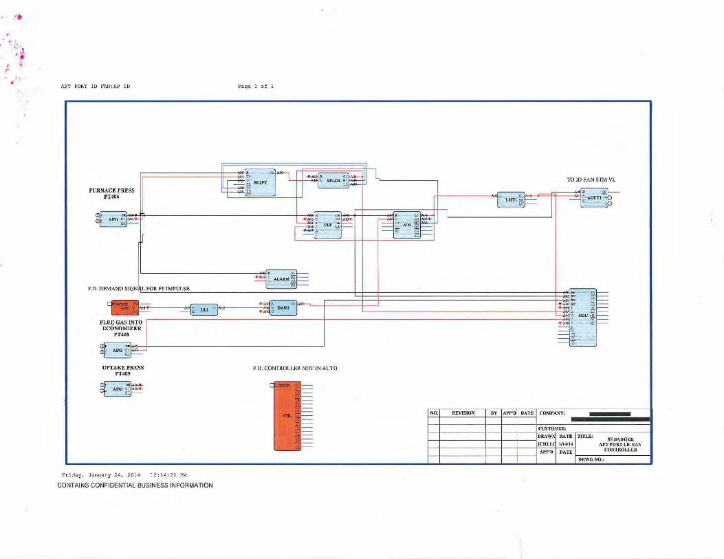
... :'
•I
·. ·~ ~ .. ~· ~
AE'T PORT ID FAN:AP ID
FURNACE PRESS l'T406
UPTAKE PRESS PT409
~ ~
Friday, January 24, 2014 12 :H: 2 1 PH
CONTAINS CONFIDENTIAL BUSINESS INFORMATION
Page 1 of 1
F.D. CONTROLLER NOT IN AUTO
NO. REVISION BY I APP'DI DATE I CO~ii'ANY:
CUSTOMER:
TO ID FAN STM VL
DOC
TITLE: SS SAUCER AFT PORT l.D. FAN
CONTROLLER
DRIVGNO.:

AFT PORT I NBO FEEDER : AOIS Page 1 o f 1
FEEDER DEMAND OUTPliT
'" ~ ~~r ~~· . '. ! BIAS T i•~ ·. )~ li ,.,.
t ; ~ TO AFT PORT AIR DISTR!BliTOR '
1 -=:;;[• li! ' EMERGENCY MANUAL OVERRIDE
~ R DO
~ ' CHR I o~J ~~ AOun { A M ~ .
I£ 1 - ~ AIM : ~ 3!f PBISW i"~J ... .. I== .. == JU' D!t-,.
R V rr --
== .. iT. I== aY 151 ....... ' pi I== ---:- . . ' ODC m: I== == Y. fE
r
== '" tc
== cr li
NO. REVISION BY APP'D DATE COMPANY:
CUSTOMER:
DRAWN DATE TITLE: SS BA OGEII.
JCUl.L( Jl151J.& AliT PO RT
APP'D DATl: AIR DISTII.JBUTOR
DRWGNO.: - ·-~ .......
Friday, J a nuary 24, 201 4 11:36 : 30 AI'!
CONTAINS CONFIDENTIAL BUSINESS INFORMATION

-'t. "
f •, . • :· ·':
,:· )·~ ... ~ ·.J, .. ; .
• # ~.·
~ ' .
~i .
'~ : ¥ •
AFT PORT INBD FEEDER: I FEED
DEMAND FROM SUB-MASTER LOWSEL
CORR. AlR FLOW
Friday, January 24, 2014 11 : 35 : 22 AM
CONTAINS CONFIDENTIAL BUSINESS INFORMATION
" Page 1 of 1
NO. REVISION
>.
' ':i t..:.:. ' ·
'· · :
'·~
TO AFT PORT INBD FEEDER VFD
. '
BY I A.PP'DI DA.TE I COMPANY:
CUSTOMF.R:
I:JA TE I TITLE:
1/15/U SSBADGER
AFT PORT INBOARD COA.L FEEDER DATE
rD~R~\~V~G~N~0~.,--------------1

AFT PORT lNBD FEEDER:lROTR Page 1 of 1
AFT PORT INBD FEEDER DE~ lAND OUT
AFT PORT INBD ROTOR
EMERGENCY MANUAL OVERRIDE . ' CHRI at ~ on
r. '
' .
NO. REVISION BY APP'D DATE COMPAN\':
CUSTOMER:
DRAWl\ DATE TITLE.: SS BADGER
.JCII LU 1115114 M 'T PORT INBD
APP'D DATE ROTOR LOOP
DRWGNO.:
Friday, January 24, 2014 11:36: 00 .AM
CONTAINS CONFIDENTIAL BUSINESS INFORMATION

AFT PORT OTBD FEEDER:OFEED Page 1 of 1
NO. REYlSION
Friday, January 24, 2014 11:37:03 AM
CONTAINS CONFIDENTIAL BUSINESS INFORMATION
OTBD FEEDER RATE TO NETWORK
30961
TO AFT PORT OTBD FEEDER VFD
BY I APP'DI DATE I COMPANY:
CUSTOMER:
DATE I 'I'ITLE:
1/1511~
PATE
SS B.'.DGER AFT PORT OUTBOARD
COAL FEEDER
~D~R\~~~G~N~0~.,--------------1

~ '. '
AFT PORT OTBD FEEDER: OROTR Page 1 of l
'
'·
"
FWD STBD OTBD FEEDER DEMAND OUT !
AFT PORT OTBD ROTOR
EMERGENCY MANUAL OVERRIDE .r. CHR.I oo
:
-
:
,,, .•
NO. REV ISION BY Ar P'D DATE C0~1PANY:
C USTOMER:
DRAW~ DATE TITLE: SS BADCER
.ICIILL l/15/J.& A''T I'ORT OUTBOARD
APP'D DATE ROTOR LOOP
DRWC NO.:
Friday, January 24, 2014 11 : 37:41 11M
CONTAINS CONFIDENTIAL BUSINESS INFORMATION

AFT PORT SUB MASTER : AP STEM! Pag e 1 of 1
l . '" ~- -ALARl't'l -~
"'
~,,
~ t ~ ;f: { :
· ~ .. .\:
l/ \ f,:
~ ~,~~ - ~ . . ',.
··'•
1 JU' ~HI-4 ~ ~I==
AFT PORT SUPERHEAT] , ~ .' :!.:": Rr :all== PRESS· PT40Z (INDIC) i. == ~ ftll-
~ . .....,.-; V ODC !&1--r---~::::::::::::::::::::::::::::::::::::::::::::::::::::::::::::::::::::::::::::::::::::::::::::::~~====~·~~ ~01-$ OR
AINl 01 Zl ~
AFT PORT DRUM PRESS • PT404 (INDIC)
~ ~
Friday, J anuary 2 4 , 2014 12 : 15 : 15 PH
CONTAINS CONFIDENTIAL BUSINESS INFORMATION
NO. REVISION
... '
:::::= t;. ==~.:~:;.~ ____ _)
AFT PORT DRUM PRESS TO P .M. & FEEDPUMPS
30%7
BY I AP.P'1 ,IIA TE I COMPANY:
:) I CUSTOMER:
fo IIIIAWN DATE I TITLE: 1---l------+--l-- ..l,--'----1 JCHLU 1124114 j SS.DADGt:H.
AFT PORTBLR STEAM PRESS LOP
~-.J.------------+---+---+,::.'~,'t.:.·· .,.·__, APP'D DATE I I l.t_ ' DRWG NO.:
;_: ~ ~
·,\
" '/ , ..
·!'

AIT PORT SUB MASTER: AP l!STR
DEMAND FllOM PLANT MASTER
AFT PORT SUPERHEAT PReSS • PT401
Friday, January 24, 2014 12:15:59 PH
CONTAINS CONFIDENTIAL BUSINESS INFORMATION
Page 1 of 1
NO. REVISION
DEMAND OUT TO F.D. AND COAL FEEDERS
AFT PORT DRUM PRESS TO P.M. & FEEDPUMPS
BY IAPP' DI DATE I COMPANY:
CUSTOMER:
:10!167
TITLE: SS B"DG&R AFT PORT DLR
SUB-MASTER W/UL\S
DRWCNO.:

AFT STBD DR!JN LEVEL: AS DRUM
DRUM LEVEL LT321
~ -
s
Page 1 o f 1
=j~x. CMPl Qlr
~~ .. ~ ~]' 1119' .. ~ -~ OR~ 0 1
PJD ~ ~: ... " ~~(~ MTH! 01.,. r=::ic --~
~
-=f ;;;I "~ At.An'fg ~·!
PARTOFLWCO
lS ROUTt ~·m ·~
HI WATER ALARM OUT
r:=: i._,.,.~
INVERTER
IL.;...f., SCLl ool-~~J*»-
FEED VALVE
~~ AOVTl ll::
I L
.. ·~ ._,, '"I I
OPC E_IL l 
! •
AFT STBD FD : AS AIR Pa ge 1 o f 1
I OUTPUT > 25%- TRUE (PAf)l
~- f ROUTI ~~
NOTI
AIR FLOW~~~====================~======tn---------,~~ FT311
"" AIN I ~ "----~
I ORRECTED AIR FLOW TO FUEL FEEDER/
~~ MTiu o}H I I ~ 10961
I :~1 ~ ALAltM
~}-
I F.D. FAN RUNNING/ L--- ----'-------------- ----- -i--t===i===========:f:f:;f[- 11 · : omo f!~ '1 Ill.]'
NO.
Friday, January 24 , 2014 2:03 :51 PM
CONTAINS CONFIDENTIAL BUSINESS INFORMATION
REVISION BY IAPP'DI OAT£ I COMPANY:
CUSTOMI:II:
TITLE: SS BADGER AliT STUD FD AIR FLOW
CONTROL
DRWGNO.:

AFT STBD FD : AS DFAIR Page l of l
==f~ Al
:tl:l R 01 "' ALARM ~ 't\1· I' ~
~ ~ SETPT r ....
==1 w _____, g
FKO.M F.D. DEI\IAND 1N F.D. LOOP TO OVER-FIRE AIR VFD
~' ~ ~l ~~ ~~~ lt 0 1 Itt- !1 AOUTl A TO D
~; BlAS - . .
I - 'l''i Tii\ ~ -E A!M i<R ~ Tl -~"1 ,.;!.;
- E l--
~ __:_::_ RP i"JI RV Pf'
__:_::_ RX IT ~ ar m " §I == OVERFIRE AIR PR :; 12. \" ODC • .,;1, == PT307 :::::: x. WE 7 'SF.: -A -
~ Alli2 ~~ == iJ! tir
. ~ == fL rr
F.D. DISCHARGE PRE s PT305
~ or~ AlNJ ~
NO. REVISION BY APP'D DATE COMPANY:
CUSTOMER:
DRAWN DATE TITLE: SS BADGER
JCIILLC 1/14/14 AFTSTBD OV.ERPIRE AIR LOOP
APP'D DA 1'K
DRWGNO.:
Friday, January ~4, 2014 2:07:47 Pl1
CONTAINS CONFIDENTIAL BUSINESS INFORMA TION

AFT STBD I D FAN:AS ID
FURNACE PRESS 1'1'306
F.D.
FLUE GAS INTO .ECONOM1ZER PT308
UPTAKE PRESS PTJ09
Friday, January 24 , 2014 2:15:04 PM
CONTAINS CONFIDENTIAL BUSINESS INFORMATION
Page 1 of 1
TOlD FAN STM VL
NO. REVISION BY IAPP'DI DATE I COMPANY:
CUSTOMER:
1-----+-------t---lli---- t----1 TITLE: SS BADGER I I AFT STUD I. D. FAN CONTROLLER
DRWG NO.:

AFT STBD I NBD FEEDER : AOI S Page 1 o f 1
HIGHEST FEEDER DEMAND OUTPUT
Friday, January 2 4 , 20 14 2 : 1 6:4 0 PJ1
CONTAINS CONFIDENTIAL BUSINESS INFORMATION
TO AFT STBD AIR DISTRIBUTOR
NO. REVISION BY I APP'DI DATE I COMPANY;
CUSTOMER:
JlRAWNI DATE I Tll"LE: f--+------+-- +--+---1JCliLLd 1115/14 SS SAilGER
AIITSTJID AIR DISTRIBUTOR
f---+------+--+--+---1 APP'D I DATE f------ - ---------1 DR\VGNO.:

l\.F7 STBD INBO FEEDER; I FEED Pa ge 1 of 1
DEMAND FROM SUB-MASTER LOW SEL
FEEDER MOTOR PROOF OF RUN
Friday, January 24, 2014 2 : 15 : 48 Pli
CONTAINS CONFIDENTIAL BUSINESS INFORMATION
NO. R.EVJSION
T O COAL FEEDER #I VFD
BY IAPP'DI DATE I COMPANY;
DATE I TITLE;
111511<
DAn
SS BADG~K
AYf STBD INBOARD COAL FEEDER
r-D-R~W~G~N~0~.-,-------------1

AFT STBD I NBD FEEDER: IROTR Page 1 of 1
AFT STBD lNBD FEEDER 'DEMAND OUT
. o·r • 70 £ BIAS TC w
Al'l STBD INBD ROTOR
EMERGENCY MANUAL OVERRIDE
,., ~ ~-& ~
NO. RI!VISION BY I""P'DI DATE I CO~IPANV:
CUSTO~rER:
Friday, January 24, 2014 2 :1 6 : 06 PM
CONTAINS CONFIDENTIAL BUSINESS INFORMATION
TITLE: SS BADGER APT STBD IN.BO ROTOR LOOP
DRWGNO.:

AFT STBD OTBD rEEDER : OFEED Page 1 of 1
Friday, January 24, 2014 2:17 : 12 Pli
CONTAINS CONFIDENTIAL BUSINESS INFORMATION
OTBD FEEDER RATE TO NElWORK
30961
TO FWD STBD OTBD FEEDER VFD
R 0 1. ;.. Cl . X CRJU o·t l 'i!J 1 9''j
NO. R...I!:\'ISION BV IAPP'DI DATE I CO~IPA.NY:
TITI.E: SS BADGU A1'T STBD OUTBOARD
COAJ.. FE.EDER
DRWGNO.:

AFT STBD OTBD FEEDER: OROTR Page l o f l
AFT STBD OTBD FEEDER DEMAND OUT
! ~~r E: BIAS 1C TV
AFT STBD OTBD ROTOR
EMERGENCY MANUAL OVERRIDE ~ R 0 1 ' 01 ;: ~URI o·r .
----:-::1• -~ . A. ~ ~ L um .~~ ----t. £... AOUTJ
NC J. == ~ Alt.r ~ I== J..!'
~ PBJ SW I'!!_J w 1!.!! I== ~
== .. '" == AV Ff - .RK l,i.; == :;::;;;;; ar E r· El == - ~ ·ooc ~
== Y. II'P =:: . y - -
== VI ii7
== E: ll
NO. REVISION BV APP'D DATE COMPANY:
CUSTOMER:
DRA\Vr. DATE TITLE: SS BADGER
.JCULU 1/15/U AFT STBD OUTBOARD
APP'D JlATE ROTOR LOOP
DRWG NO.:
Frid dy , January 24 , 2014 2 : 1 7 : 31 PH
CONTAINS CONFIDENTIAL BUSINESS INFORMATION

Af'T STBD SH - PM: AS STEAM Page 1 of 1
.. AFT STID SUPERH PRESS • PT3D2 (IND )
NO. REVISION BY Aff'D DATE COMPANY:
CUSTO MER:
DRAWN DATE TITLE: SS BADGER
J CIJLL 1124/1 4 Arrr srno BLI< Af'J•'D DATE
STEAM PRII.SS LOOP
DRWG NO .:
Friday, January 24, 2014 2 : 25 :21 Pll
CONTAINS CONFIDENTIAL BUSINESS INFORMATION
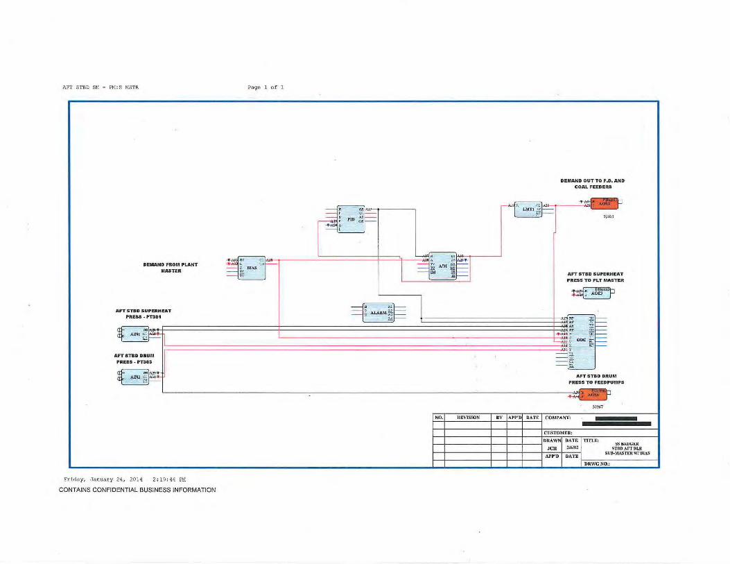
AFT STBD SH - PM: S MSTR
PII:MAND FROM PLANT MASTER
AFT STBD SUPERHEAT
Page 1 of 1
~
~a=l ~~r E BIAS K ,..,
811 I . .. ""' 1
I ~~WM~~
DEMAND OUT TO F. D. AND COAL FEEDERS
AFT STBD SUPERHEAT PRESS TO PLT MASTER
~ ~
PRESS· PT301 RP
AFT STBD DRUM PRESS. PT303
~ .
.
Friday1 January 2 4, 201 4 2:1 9 : 44 Pl1
CONTAINS CONFIDENTIAL BUSINESS INFORMATION
NO. REVISION
AFT STBD DRUM PRESS TO FEEDPUMPS
~
BY I APP'DI DATE I COMPANY:
CUSTOMER:
30967
TITLE: SSBADGER
Sl'BDAFTlJLR SUB-MASTER WI BlAS
DRWGNO.:

FEEDPUMP 1 : FEED 1
FEED PRESS # I PTS01
ASBLR DRUM PRESS
Page 1 of 1
SETPOINT LIMITING SO - 150 PSIG
APBLR DRUM PRESS ~A oo r on ~: suao 01
] I . a Sl!:U
~ tUGHEST DRUM PRESS OF 4
J'PBLR DRUM PRES
Thursday, January 30, 2014 10:13 : 26 AM
CONTAINS CONFIDENTIAL BUSINESS INFORMATION
NO. REVISION BY IAPP'DI DATE I CO~IPANY:
CUSTOMER:
f--t- - - - - - +-- + --+- --JDRAWNJ DATE I TITLE: JCIJLL d 1/JUI U
SS BADGER FEEDPIJM H I DIP
CONTUOLLER APP'D I DATE ~0-R-W~G-N~O-.: ----------~

FEED PUMP 2 : FEED 2
FEED PRESS #2 PTS02
ASBLR DRUM PRESS
Page l of l
SET POINT LlMITING 50-150 PSIG
+M~'-----'
APBLRDRUMPRESS ~' ol ]-'IH ~~ SUB L 01J •· .a SEU l
~ FPBLR DRUM PRES
~ ~
Thurs day , January 30 , 2 0 1£J 10: 1 6: 03 AM
CONTAINS CONFIDENTIAL BUSINESS INFORMATION
HIGHEST DRUM PRESS OF 4
NO. REVISION BV I APP'DI DATE I COMPANY:
CUSTOM ER:
l'l'l"LE: SS PADGER FEEDPUMP #2 DIP
CONTROLLER
DRWGNO.:
~ '

FEED PUMP 3 : FEED 3
FEED PRESS NJ PT503
ASBLR DRUM PRESS
Page 1 of 1
SETPOINT LIMITING so -ISO PSJG
APBLRDRUMPRESS ~· ooj• on ~~ SU81 °1]
I , _ 8 SILl
~ -HIGHEST DRUM PRESS OF 4
FPBLR DRUM PRES
Thursday, January 30, 2014 10:14:56 AM
CONTAINS CONFIDENTIAL BUSINESS INFORMATION
NO. REVISION BY IAPP'DI DATE I CO~U'ANV:
CUSTOMER:
TITLE: SS BADGE R
FEEDPUMP *l DIP CON'I'ROLLER
DRWGNO.:

FWD PORT DRUM LEVEL : FP DRUM Page 1 of 1
PARTOF LWCO
~~ CMPt U!,l . ( ROUTl ~
. L" ROUTl rJ ~ Olf-'--, ~· OWE~ ~ ~l§r HJWATERALARMOUT -----1* SITPT I L f- I& ,., SPLIM ~ -----~~ Alftl :
~m: - ==lw cl!f-- ' • · "' · ~1.1) n !-- LAITI ~F'-- FEED VALVE
DRUM LEVEL J.J:_r--LT221 . ~
~-----;~~~::::::::::::::::::::::::::::::::::::::~~~~:·----~o~R~:=ttt-__j ~ ~~ AOUTI C!t'- AlNI g:'f.\o>- ~1 : PID ~~ I l.._-_ __ ,-<Il' ~.r----- ~~ ~~ ..:1--
i==l.~ HTHl Ol.. ---1 1 INVERTElt
~:~ scu ~~
~ ~ ALARM Nt:::: L -.ij- ~ VJ==
: ~== i' :J! -
,__,_., ~ ooc ~== I
l r--------------------t-~===============4============================~======================================================~~~ ~--- 1 ::: i)I == EI I
STEAMFLOW TO PLANT MASTER I
STEAMJ''LOW ~41&} i
J''TllJ 30%1
r--------r------------------~-~~ ~~~
~ .. ~ L.....f• .I. -----1 • T2!--A00 Ol Y. CHIU C"! o. MTIIJ 01 ~ y BATOT r_~ t-:---
..._ _ _:!ll':;;J·:J- -tc J I --g N~
r------, r NO. REVISION BV APP' D DATE COMPANY:
l ~!1
scu ":}M+-~1~~ DIVt 01
CUSTOMER:
f---t------------+---+---t-----I DRAWN OAT& TITL£: SS BAJ>Gt R ~CIILLC 1/J.UI~ FWD PORT DRUM LEVEL
f---t------------+---+---t----+~AP~P='~D+-D=A~T=E~ CONTROL
DRWGNO.:
Friday, January 24, 2014 2 : 29 :42 PM
CONTAINS CONFIDENTIAL BUSINESS INFORMATION

. ' . ,.. {~ .. -.. ~f'
·~ ! r ' ! 1 ·r,.
, .._ \
' · ' t.
FWD PORT FD: FP AIR Page l o f l
f ..
I OUTPUT > 2S% =TRUE (PAF)I '
---{~L C>IPI 0!j l" ROll!' ~
\
I ~~. Olh .-.{· ·;~~I l I TO F.D. VANES I r---!1H -----i~fi S!TPT (" SPWI i:ijMi-~ ~a t!
~ NOTl ~ · L-~!::..: ' 0~~ s AOUTI -~ UJ Utl"l Il}- [_£ •
AIR FLOW '-- - r
FT211 It Olt .R OJ~
~ c:a ~I' Ol 1i. Jo!~ (Mrf-
AJNI o!~ ~J PID AI!" .,...__ --:-:] TV A/,.1 fl\. 1----l_ _ _ ,::ll::.:;~:..,.--- , ~~----- ~ .... q.t--- ,
DEMAND ---it -j~ lfilt:= '!'
--:-::f: MTHI OlJ~ j 0
/oRRECTED AIR FLOW TO FUEL FEEDER'
I ~lk Ul ........r: •tTUl Ol l ~ • RATIO ro r::-:- ---{c j ~ *' J R "-1 ', 30961 !
~~ A.LARM ~ l~--~~J· ~
1 F.O. FAN RUNNING' ,_ E m= ~
Cll A 0 1 1---:- !r ~~ DINt ~1- l- Non '---~ • wr-J ~v ODC !l!r--== ~ ITt:::
-111
==~ -fi. '----'
NO. REVISION BY APP'D DATE COMPANY:
1
CUS'rOMER:
f---f------+ -+- -f---jDRAWN DATE Tin.£: SS BADGER ~CIILL£ 1/WI~ FWD PORT FD AIR FLOW
f---f------+-+--f--+AP~P~'D~~D~A~TE~ CONTROL
L._______ ______ _ DRWCNO.:
Friday, Januar y 24 , 201 4 2 : 30 : 37 PM
CONTAINS CONFIDENTIAL BUSINESS INFORMATION
.,
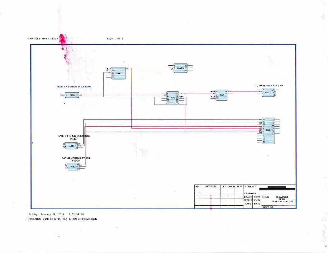
FND PORT FD: FP OFAIR "'
''
I . ,.
~if ~ ~
t( :
' ~ ,_
..
t'ROM ll. D. DEMAND IN F. D. LOOP
Page 1 o f 1
TO OVER-FIRE AIR VFD
X CHRI01 . ~ ----c::JD .
I .. '"r-----1 -Rv !.ti--
l I -! ~~
~:===========================~================================~~~~~~~~~~~~~~~~~~~~~~~~i ~ ~r--11 : ~~~ Ill _ -; ~~ OVERFIRE AIR PRES
PT207
aft AINl ~J;:: I <If ~
RE
F.D DISCHARGE PRESS PT205
~ -.
Friday, Januar y 24, 2014 2:33 : 5q Pt1
CONTAINS CONFIDEIIJTIAL BUSINESS INFORMATION
== ~, - iii , == ... r_·t _ _ ~
NO. REVISION BY I APP'DI DATK I COMP ANY:
CUSTO~fi:R:
DRA WNj DATE I TITLE: f--t----:----+--+--t----1JCHLLd 1114/U
SSBADGER FI'FO
OVEIU'IRE AIR LOOP
f--t-----::--- ---l- ---l--t---1 APP'D I DATE I I ' DRWGNO.:

FWD PORT lD F.I\N : FP ID
FURNACE PRESS 1'1'206
UPTAKE PRESS 1'1'209
Friday, January 24 , 2014 2 : 45 : 26 Pll
CONTAINS CONFIDENTIAL BUSINESS INFORMATION
Page 1 o f 1
TOlD FAN STM VL
NO. REVISION BY I APP'DI DA Tit I CO~lPANY:
CUSTOMER:
DRAWNj DATE I TITLE: f---+------------+---+ ---+----_,.ocuLLd 1114/lJ
SS BADGER •WD PORT I. D. FAN
CONTROLLER APP'D I DATE
~-+------------+---~---+----~ r~D~R\~V~C~N~0~.:-------------1

FWD PORT INBD FEEDER:ADIS Page 1 of 1
GREATEST FEEDER DEMAND OUTPUT
EMERGENCY MANUAL OVERRIDE
Fr i day, January 24, 2014 2: 35:07 Pt1
CONTAINS CONFIDENTIAL BUSINESS INFORMATION
TO FWD PORT AIR DISTRIBUTOR
NO. REVISION BY I Ari"DI DATE I COMPANY:
CUSTOMER:
DRA WNI DA T£ I TITLE: f---t-------+----t---t----iJCHLLd 1/15/U SSBADGER
F\VD110RT AIR DISTRIBUTOR
1-:--+------+--+--+--_, APP'D I DATE 1--:-=-c-:-::-:-:-::------- -1 DRWGNO.:
'\

FWD PORT INBO FEEDER : I FEED Page 1 of 1
~
TO FWD PORT !NBD FEEDER VFD
DEMAND FROM SUB-MASTER LOWSEL
~ et~[.r.. ollu lt ~ '9~7' 1 ''~~ X t1lRJ otl,,&'l 1 ~
friduy, January 24, 2014 2 : 34 :24 PH
CONTAINS CONFIDENTIAL BUSINESS INFORMATION
•• ' . ( \ ..
•· ! NO. REVISION BV I AI'P'DI DATE I COMPANY:
DATE TITLE: SS Bil.liGER 1/ 15114 FWD rORT INBOARD
APP 'D DATE COAL fEEDER
~D=R,=v=G=N~O~.,-------------j
,.;
~~ .,. ~ . ··~ ... ·'. . ..·i·. • i)l' '
~

FWD PORT INBD FEEDER: IROTR Page 1 o f 1
FWD PORT INBD FEEDER DEMAND OUT
~ FWD PORT INBD ROTOR
~ ....
EMERGENCY MANUAL OVERRIDE I ~. 0 , . ~ • d,. CHRt o·']'" ~ AOUU '-~A o0~ 1'-----· -
-f,c- _ ] ==I~ AM ~~ ~$ PBI~'W ?[r i:J ~~
Friday, January 24, 2014 2 : 34 :49 Ft1
CONTAINS CONFIDENTIAL BUSINESS INFORMATION
_ ,.. '"1--== : H~ -Rr §!-
~ ~- ~== l_ _________________________________________________________________ ::_·~~ DOC ~===
_ , - Ul - ill' - CL - ,IT:.:· '----~
NO. REVISION BY APP'D DATE COMPANY:
CUST0~1ER:
, - -1-------------+--+---f------jDRAWN DATE 1'1TLE: SSBADGER 1- .JCRLLC 1/15/ U FWD PORT lNBD ~-4------------~--~---4----~~Ar=r=•=o~D~A~T=E~ ROTORLOOP
DRWGNO.:

FWD PORT DTBD FEEDER: OFEED Page 1 of 1
OTBD fEEDER RATE TO NElWORK
30961
TO FWD PORT OTBD FEEDER VFD
REVISION BY I '"P'DI D~~ T_E I CO~U'ANY: NO.
ADDEDCA.B'fD.fP I JCU I 1 III.Yf l ,.
CUSTOMER:
DATE TJTL£: SS BADCER 1/IS/1• li'\VD PORT OUTBOARD ~-+------------+---~---+----~:c~ZL DATE COAL FEEDER
DRWCNO.:
APP'D r-r-------+--+--r-~
Wednesday, January 29, 201-4 8:38:42 AM
CONTAINS CONFIDENTIAL BUSINESS INFORMATION

n;o PORT OT BD FEEDER : OFEED Page 1 o f 1
NO. REVISION
Frida y, Janua ry 24, 2014 2 : 35 : 4 6 Pl1
CONTAINS CONFIDENTIAL BUSINESS INFORMATION
OTBD FEEDER RATE TO NElWORK
3096 1
TO FWD PORT OTBD FEEDER VFD
HV I AI'P'DI DATE I COMPANY:
CUSTOMER:
TITLE: SS B.WGEK FWD PORT OUTB01\RD
COAL FEEDER
DRWG NO.:

'!.
FWD PORT OTBD FEEDER :OROTR Page 1 o f 1
FWD PORT OTBD FEEDER DEMAND OUT
~ ~~ ~ BIAS
"' FWD PORT OTBD ROTOR
EMERGENCY MANUAL OVERRJDE
~ • 01 + r~ pi+ ) A oi~ . .. LMTI K:i CHRI ctf ) ~ AOUT'l
'"' .L ~ ~ AIM ~ I== cr ~ PBIS\V ptf "" .. I== ... ..
== "" '" I== AV If
== "" u. I== ar ~
~ ; P' I==
== ., ODC fir I== Y. ~ y
== Ul fr":"
== R ~
·'
NO. REVISION BV APP 'D DATE COMPANY:
CUST0~1ER:
DRAWN DATE TITLE: SS BADCER J CHLL< UIS/U FWD PORT OUTBOARD
Arr'D DATE ROTOR LOOP
DR\VGNO.:
Friday, Janua ry 24, 2014 2 : 36 : 08 Pl1
CONTAINS CONFIDENTIAL BUSINESS INFORMATION
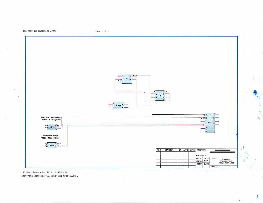
oWD PORT SUB MASTER: FP STEAM Page 1 o f 1
I =13 .
-
FWDPORTSUPERHEA~--------------------------------------------------------------------_j======================================~~~--~~ PRESS • PTZOZ (INDJC)
FWD PORT DRUM PRESS • PT204 (JNDJC)
a} A1N4 :~ I err ~·~
Friday, January 24, 201 4 2 ; q0;33 PM
CONTAINS CONFIDENTIAL BUSINESS INFORMATION
NO. REVISION BY I Al'l"DI DATE I COMPANY:
CUSTOMER:
f--+------------+---+ ---+-----IDRAWNj DATE I TITLE: JCllLLJ 1/2-'/14
SSBADGER PWDI'ORTllLR
STI::AM I•RESS LOOP
f---+------------+---+---+-----1 AI'P'D I DATE 1-::-==-:-:---------------1 DRWGNO.:
#. .
' ..
! ·.
~

FWD PORT SUB MASTER: FS 11STR
DEMAND FROM PLANT
MASTER
FWD PORT SUPERHEAT
PReSS • PT201
Friday, January 24, 2014 2:41:25 PM
CONTAINS CONFIDENTIAL BUSINESS INFORMATION
Page 1 of 1
NO. REVISION
DEMAND OUT TO F.D~ AND COAL FEEDERS
FWD PORT DRUM PRESS TO P.M. & FEEDPUMPS
BY IAI'P'DI DATE I COMPANY:
CUSTOMER:
30967
TITLE: SSBADG.ER
FWD PORT'RLR SUS-MASTER WI BIAS
DRWGNO.: ·'

FWD STBD DRUM LEVEL:FS DRUM Page 1 of 1
PART OF LWCO
~~b CMPt '='1.f . !:. :m 1 ROUTt e
""
r ROUTI ~:m =:::~sBTPT 01h ~ ...,~ SPUM ~b:t:JII - ~v ~~ HI WATER Al A:OUT
1~);[ • L'u~=tl - n: AIM )QI==I ~w - w »~ A m
DRUM LEVEL U~ "1 LMT I ti:l== FEED VALVE
LT121
~ ..,~ • o• L A j; ><:! AINI ol~Ai»-=- L_____<;~ r 01~ !'. AOUTI
~J-- -~~ ~: PID ::~ r==t-~' >rnu OL . ~t I
4 ! ALAMM ~~
INVERTER
~~1 scu~ •
: ~t=: : ~t=: l' o-~t-
r-----------------~~~r===============f=========================t==========================~;;;;;;;;;;;;;;;;;;;;;;~~~·~ ~ onc ~t=: I ~ 3f~ :::::: Bt -=== ~ = ---'
STEAMI1LOW TO PLANT MASTER
STEAM}'LOW ~ ~,'113 l 30%1
~ ool-o- A ---:-:: ~ ~f I=: AlNl o! r ··- · x CIIRI .,L..._ ~~ MTIII 01 ~.!! IATOT ""~
r£r- -==!e ~1 ttl;;>:::........ "' Yf=- I
~•1 00. NO. RI VISION BY AP P'D DA'l'li! COAIPAl'm
'-----..l~h~SC~Ll~.u~i~ : DlVt 01 CUSTOMER:
I HLDI 01 DRAWN DATE TITLE:
f--1------~--+-~~--+-C_HL_L~(J~Il~~~~~~ ~VDS~~~~~~LEVEL , f--j------+--t-__.j- - -J APP'D DATE CONTROL
DRWGNO.:
Friday, January 24 , 201 4 12:29 : 43 PM
CONTAINS CONFIDENTIAL BUSINESS INFORMATION

~0 STBO FO : FS AIR
AIRFLOW FT111
Friday, Janua ry 24 , 2014 12 :4 0 :33 PH
CONTAINS CONFIDENTIAL BUSINESS INFORMATION
Page 1 o f l
PID
lTB: IF P.O. I' AN IS NOT RUNNING OR J.D. CONTROL NOT IN AtrrO. f .D. STAYS IN STANDBY SYNC WTrn
OUTPUT OF ZERO.
I OUTI'UT> 2S% ~TRUE(PAF) I
I ORRECTED AIR FLOW TO FUEL FEEDER!
30%1
NO. REVISION BY I APP'DI DATE I COMPANY:
C USTOMER:
DUW ~-+-----------4--~~--~---i.CULL
r---r----------+ --+-- +----l APP'D
DATE TITLE! SS BADGER 111-1/14 FWD STBD f D AIR FLOW
DATE CONTROL
DRWG NO.:

FWD STBO FD; FS OFAIR Page 1 of 1
~Jt. ll ~R 0 1 ~ ALARM * ~~TV - ~ M ~f,i· Sf'l'l"f --till:... -----j'-'r,_::.p ----'
FROM F. D. DEMAND IN F.D. LOOP TO OVER-FIRE AIR VFD
r;---;;;'f,...._, _______ _:~!!~~A ot --:::J: le -\Jt 01 A ro)r ~p AOUTI , CHRI OY . , ~r.::-:- a~ PJAS ~ -
1
== ~ AIM .~~h ==t¥1 c_ __ ..:;r-
- §B *~I I
JW ru !---
r-t-------------------------4-------------------------------+------------------------------------------= ---~:- lf~
1 ,-t~========================~================================~~~~~~~~~~~~~~~~~~~~~~~~---!!1 ~ ·fiT~ ~ - ~l== " ODC !1k~ :< HD I---
f.D, DISCHARGE PI :~l :::::: J... !'!~ PT105J == *".;
~ AIN2 ~ .
OVERFIRE AIR PRES PT107
af+ AJNr~~ <If l:i
Fri day, Januar y 24 , 201 4 12:44:51 PH
CONTAINS CONFIDENTIAL BUSINESS INFORMATION
- Ci; ---<.:r=··· __ _)
NO. REVISION BY APP'D DATE COMPANY:
CUSTOMl!R:
1--t------t--+--+---JDRAWN DATE TITU; SS BADGER
~-1------4---+--4---+J~C=H=LL=.C~I=/1~4/=1·~ OV~~r~LOOI' ~-1------4---+--4---l 1\PP'D DATE f------------1
DRWGNO.:

FWD STBD ID FAN: FS ID
FURNACE PRESS PT106
Friday , January 24, 2014 12 : 52 : 43 PM
CONTAINS CONFIDENTIAL BUSINESS INFORMATION
Page 1 o f 1
SITPT
F.D.
TOlD FAN STM VL
~1025
NO. REVISION BY IAPF' DI DATE I COMPANY:
CUSTO~fi:R:
I I I I I TITLE: ss BADGER FWD STUD I. D. FAN
CONTROLLER
DRWGNO.:

8>D STBD INBD FEEDER:ADIS Page l of l
:j
OTBD FEEDERDMD
HIGHEST OF INBD OR OTBD FEEDER DEMAND
EMERGENCY MANUAL OVERRIDE
Friday , January 24, 2014 12:54:23 PH
CONTAINS CONFIDENTIAL BUSINESS INFORMATION
TO FWD STBD AIR DISTRffiUTOR
NO. REVISION BY I APP'DI DATE I CO~IPANY:
CUSTOMER:
DRA WNI DATE I TITLE: 1----1--------t---J---1----JCHLLd 1115/JJ SSBADGER
FWDSTBD AIR DISTRIBUTOR
APP'D I DATE ~-t------+--4---t--4 r~D~R~W~G~N~0~.,--------1

FWD STBD INBD FEEDER: I FEED Page 1 o f 1
Friday, .January 24 , 2014 12:53:39 PH
CONTAINS CONFIDENTIAL BUSINESS INFORMATION
INBD FEEDER DEMAND TO NElWORK
TO FWD STBD INBD FEEDER VFD
NO. REVISION BY I AI'P'DI DATE I COMPANY:
CUSTOMER:
DRAW'-1 DATE I TITLE: 1--t------ +--+--t---iJCHLLd 111~1• SSBADGER
FWD STBD I NBOARD COAL FEEDER
APP'D I DATE ~-+------+--+--+--~ ~-D-R\_V_G_N~0~.,--------1

FWD STBD INBD FEEDER: IROTR Page 1 of 1
FWD STBD JNBD FEEDER DEMAND OUT
. ·r· ,._ 1' "i'' -~.k BIAS
"'
EMERGENCY MANUAL OVERRIDE
~- 01§ .. -~ . .M . • TV - NA
~~ n;. AIMw [;!£ PBISW ••]>llf~l ll> MD- - ~
~
Friday, January 2 4, 201 4 12 : 54:01 PM
CONTAINS CONFIDENTIAL BUSINESS INFORMATION
FWD STBD JNBD ROTOR
~ 'l{r. CHRI o·+·~~ ~ • Q AOUTJ -
'"~ IT . g
Cll
5.i ODC IT . !:ill
NO. REVISION BY I APP'DI DA. TE I COMPA.NY:
CUSTO~fER:
TITLE: SS BADGER FWD STBD INBD
ROTORLOOI'
DRWGNO.:
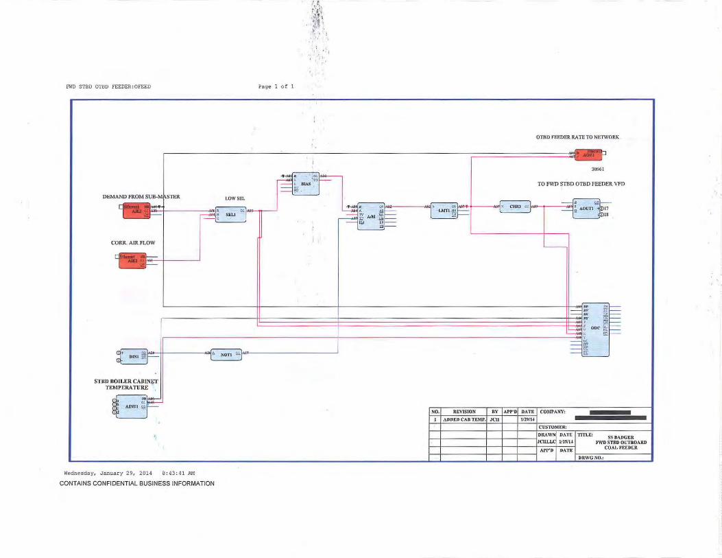
niD STBD OTBD fEEDER:OFEED Page 1 of 1
Wednesday, January 29, 2014 8 :4 3 : 41 AM
CONTAINS CONFIDENTIAL BUSINESS INFORMATION
' f 'r·'· ..... ,. ! .. . ,
' ·~,, ~ .. , t 'j., ·' . : ~
.:· , ' I
NO.
OTBD FEEDER RATE TO NElWORK
30961
TO FWD STBD OTBD FEEDER VFD
R£VJSION av jAPP'DI _o~~E- 1 COMPANY: ADDED CAB T£A1P.I JCH I 1 lll71H
CUSTO~Jt:R:
TITL£: SS BADGER FWD STBD OUTBOARD
COAL FEEDER
DRWG NO.:

EWD STBD OTBD FEEDER : OFEED Page 1 of 1
.ti OTBD FEEDER RATE TO NElWORK
30961
TO FWD STBD OTBD FEEDER VFD
NO. REVlSION BY I Arr'DI DATE I COMPANY:
CUSTOM[R:
DATE TITLE: SS BADGER 1/15/14 FWD STUD OUTBOARD DATE COAL FEEDER
DRWGNO.:
Friday, January 24, 2014 12 : 55:25 PM
CONTAINS CONFIDENTIAL BUSINESS INFORMATION

FWD STBD OTBD FEEDER : OROTR Page 1 of 1
FWD STBD OTBD FEEDER DEMAND OUT
. Olr · > T~
' BIAS TC w
EMERGENCY MANUAL OVERRJDE
Friday, January 24, 2014 12:55 ; 44 PH
CONTAINS CONFIDENTIAL BUSINESS INFORMATION
NO.
FWD STBD OTBD ROTOR
1'1' iT Bi "'@
ODC ~ !!It
REVISION BV 11\l'P'DI DATE I COMPANY:
CUSTOMER:
TITU: SS BADGER I I I I I J'\VD STBD OUTBOAllD
ROTOR LOOP
DRWGNO.:

FWD STBD SUB MASTER:FS STEAM Paqe 1 of 1
kl Jt E t AU.RA-f ii:! " ;;r
l ~. ,, i Alltt ~~
I u ""i r---av .trr--
~: ~~ FWD &TBD SUPfRHf1,; - ' f!ii--
PRESS· PT102 (INDI I - ~ ODC ]!!;~
~--~============================================================================================~~- 3k' ~r--~ AINl ~I • ¥ ~ ~ ~
FWD STBD DRUM PII!SS • PT1D4 (INOICI
~ ~
Friday, J a nuary 24, 2014 1 2 : 34 : 00 PM
CbNTAINS CONFIDENTIAL BUSINESS INFORMATION
NO. RltVJSION
== ~ = --___J FWD STBD DRUM PRESS TO P,M, &
FEEDPUMPS
BY IAPP' DI DATE I COMPANY:
CUSTOMER:
11TL"l: ss I'ADCER FWDSTBDBLR
S'Tl..Ut PRISS LOOP
DRWG NO.:

FWD STBD SUB MASTER: FS HSTR
Friday, January 24, 2014 12:57:59 PM
CONTAINS CONFIDENTIAL BUSINESS INFORMATION
'• 7:;
'· .. ~ . . ,
Page 1 of 1
NO. REVISION
DEMAND OUT TO F.D. AND COAL FEEDERS
FWD ST BD SUPERHEAT PRESS TO PL T MASTER
~ ~··
FWD STBD DRUM PRI!SS TO FEEDPUMPS
BY I APP' DI DA TB I CO~trANY:
CUSTOMER:
J0967
TITLE: SS BADGER FWDST8D DLR
SUO..MASTEK WI BlAS
DR\VGNO.:
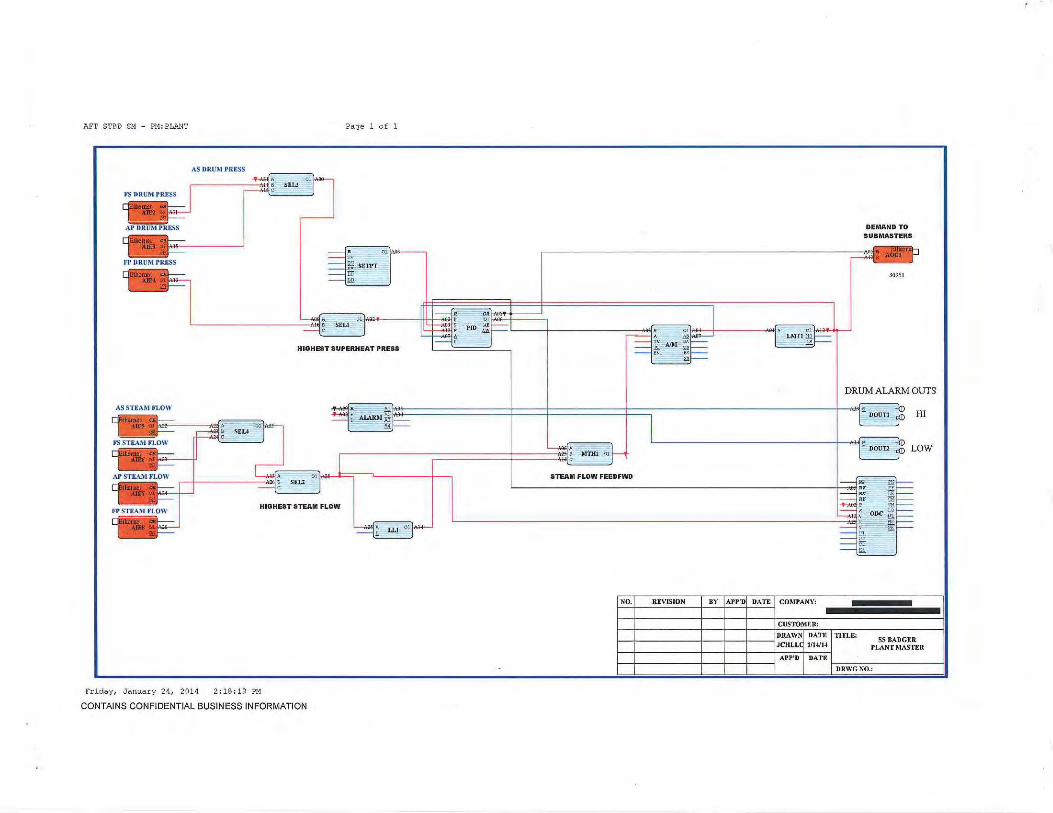
AFT STBD SM - Pl1: PLANT Page l o f 1
AS STEAM FLOW
Friday, Januar y 24, 2014 2 :18 :1 9 PM
CONTAINS CONFIDENTIAL BUSINESS INFORMATION
DEMAND TO SUB MASTERS
.\0%1
DRUM ALARM OUTS
STEAM FLOW FEED FWD
NO. REVISION BY I APP'DI DATE I COMI'ANY:
C USTOMEII.:
DRAWNI DATE I TITLE: f---j--------t--+--1----JJCHLLd 1/Wl4
HI
LOW
SS BADGER PLANT MASTEl!
Al'P'D I DATE I f---t------+--+--t---1 ~~D~R=~=·G=N~O~.-,------~;

STA. POWER TERMINALS CABINET DC POWER DISTRIBUTION
~ I'" FROM PORT PANEL FUSE F1
ANALOG INPUTS
+ AFT PORT DRUM LEVEL
CABLE N: K1320
250 OHM + AFT PORT STEAM FLOW
250 OHM CABLE #: K1322
L------1 CABLE SHIELDS GROUNDED AT BOILER CABINET END ONLY
ANALOG OUTPUTS
CABLE #: K1317 AFT PORT FEEDWATER VALVE POSITIONER
CABLE SHIELDS GROUNDED AT BOILER CABINET END ONLY
ETHERNET SWITCH - PORT # 1
RJ45 PORT CABINET
lr'1l rr'1l
ALARM RELAY OUT
Nc@J COMG81-- TO STA 14 - TERM 28 ~ & PORT BLR CAB PLC F1B
NO G9l TO STA 14 - TERM 29 ~ & PORT BLR CAB PLC S4TERM36
RELAY 1/2
NC~ COM~ No§
0
(f) (f) w z Ui ::J a:l
~ i= z

STA. POWER TERMINALS CABINET DC POWER DISTRIBUTION
FROM PORT PANEL FUSE F5
FROM PORT PANEL FUSE F35
ANALOG INPUTS
250 OHM CABLE H: K1720
250 OHM CABLE #: K1722
AFT PORT OVERFIRE AIR PRESS
CABLE SHIELDS GROUNDED AT BOILER CABINET END ONLY
AFT PORT F.D. DISCHARGE PRESS
CABLE #: K1723
250 OHM
ANALOG OUTPUTS
APFDFAN - VFD
OFA FAN - VFD
ETHERNET SWITCH - PORT #5 RJ45 PORT CABINET
[OJ [OJ
ALARM RELAY OUT
Nc!E] COM§- TO STA16 & 16 - TERM 26
NO~ TO STA16 & 16 - TERM 29
RELAY 1/2
NC§] coM @2]
NO~
z 0
~ a:: 0 u.. ~ en en w z Ui :::> CD --' <(
i= z w 0 u:: z 0 ()
en z
---- ------------------------------~~
CABLE SHIELDS GROUNDED AT BOILER CABINET END ONLY
SS BADGER STATION 17 - AFT PORT FORCED DRAFT
WIRING DETAILS
OOt.ltt.;.;;.,..\J'ti_R:
Stt:t. _ OF .-
0
z 0 ()
. 4

STA. POWER TERMINALS CABINET OC POWER DISTRIBUTION
~ ; DC+ """ """' " " " ME "
ANALOG OUTPUTS
AP INBD FEEDER - VFD
INBD ROTOR - VFD
CABLE SHIELDS GROUNDED AT BOILER CABINET END ONLY
ANALOG OUTPUTS
~-+-r--------~53
CABLE #: K 1533 APAIRDIST - VFD
,--· 55
CABLE SHIELDS GROUNDED AT BOILER CABINET END ONLY
ETHERNET SWITCH - PORT #3 RJ45 PORT CABINET
M rrail
ALARM RELAY OUT
NeE] COM~ TO STA14 & 16 - TERM 28
NO§-- To STA14 & 16 - TERM 29
RELAY #2
NC~ coME] No§
0
~ Cl) Cl) w z iii ::> m --' <(
i= z w 0 ;:;: z 0 l)

STA. POWER TERMINALS CABINET DC POWER DISTRIBUTION
~ ir FROM PORT PANEL FUSE F4
ANALOG INPUTS
AFT PORT FURNACE PRESS
CABLE #: K1620
250 OHM AFT PORT FLUE GAS INTO ECONOMIZER
250 OHM CABLE #: K1 622
CABLE SHIELDS GROUNDED AT BOILER CABINET END ONLY
AFT PORT UPTAKE PRESS
CABLE #: K1 62.3
250 OHM CABLE SHIELDS GROUNDED AT BOILER CABINET END ONLY
ANALOG OUTPUTS
+
COM CABLE#: K1617 AP I.D. STEAM CONTROL VALVE POSITIONER
r """' '"'"" '"'""" .. "'"'' CABINET END ONLY
ETHERNET SWITCH - PORT #4
RJ45 PORT CABINET
M ~
ALARM RELAY OUT
Nc@J COM§-- TO STA15 & 17 - TERM 28
NO~ TO STA15 & 17 - TERM 29
RELAY #2
NC~ COM~ No§
0

250 OHM
250 OHI.1
250 OHM
250 OHM
•' . ~
. I. 1 .. . . . ,\ 'I, •
FROM PORT .PANEL FUSE F6 ~ ir··. . • '
+ AFT PORT SUPERHEAT PRESS - CONTROL
CABLE #: K1 820
CABLE #: K1822 AFT PORT DRUM PRESS - CONTROL
CABLE SHIELDS GROUNDED AT CABINET END ONLY
AFT PORT DRUI.1 ·PRESS - IND
CABLE f : K1823
+ AFT PORT SUPERHEAT PRESS - IND
CABLE #: K1B41
ETHERNET SWITCH - PORT #6
RJ45 PORT CABINET
M rFTI
ALARM RELAY OUT
NC@J
COM§- TO STA17 & 19 -TERM 28
NO~To STA17 & 19- TERM 29
RELAY #2
Nc§] CoM§]
No§
SS BADGER STATION 18 - AFT PORT MASTER
WIRING DETAILS
DfU.IfiNG N..t&:R:
~ET-Of -
z 0
~ :; a:: 0 u. ~ (f) (f) w z en :::> ttl ...J <(
i= z w 0 u:: z 0 0 (f) z ~ z 0
I 0
0

STA. POWER TERMINALS CABINET DC POWER DISTRIBUTION
~ ii OC+ moM "" ema ""' "
ANALOG INPUT UNIVERSAL # 1
REF. JCT
PORT CAB TEMP - TI431
~ > ..
ANALOG OUTPUTS
AP O T BD FEEDER - V F D
OTBD ROTOR - VFD
CABLE SHIELDS GROUNDED AT BOILER CABINET END ONLY
ETHERNET SWITCH - PORT #2
RJ45 STBD CABINET
M rF11
ALARM RELAY OUT
NC IE] . COM~ TO STA 13 & 15 - TERM 28
NO~T~ sTA 13 & 1s - TERM 29
RELAY #2
NC ~ COM@2J
NO~
z 0
~ 11:: 0 LL
::= Cf) Cf) w z (i) :::> Ill --' ~ fz w 0 u:: z 0 ()
Cf) z
r---------------------------__, ~
0
z 0 ()

STA. POWER TERMINALS CABINET DC POWER DISTRIBUTION
~ ;---ANALOG INPUTS
+ AFT STBD DRUM LEVEL
CABLE #: K1220
250 OHM + AFT STBD STEAM FLOW
250 OHM CABLE #: K1222
'------i CABLE SHIELDS GROUNDED AT BOILER CABINET END ONLY
ANALOG OUTPUTS
CABLE #: K1217 AFT STBD FEEDWATER VALVE POSITIONER
CABLE SHIELDS GROUNDED AT BOILER CABINET END ONLY
PANEL FUSE F12 ETHERNET SWITCH - PORT #12
RJ45 STBD CABINET
rr-'11 rr'1l
ALARM RELAY OUT
NC [E) COMGBl- TO STA 1 1 - TERM 28 EJ . & PORT BLR CAB PLC F2D
NO G9l TO STA 11 - TERM 29 ~ & PORT BLR CAB PLC S5TERM36
RELAY #2
NC~ coM@2]
No§
SS BADGER STATION 12 - AFT STBD DRUM LEVEL
WIRING DETAILS
DI<AWt~.u~r ~ ...... ~~ ~f-f _ Of _
-·-- - - ---
z 0 i= ~ ::;: 0:: 0 u. ~ en en UJ z ii5 => Ill -' ~ I-z UJ Cl u:: z 0 ()
en z ~ z 0 ()
I
0

STA. POWER TERMINALS CABINET DC POWER DISTRIBUTION
FROM STBD PANEL FUSE FB
FROM PORT PANEL FUSE F17
ANALOG INPUTS
FWD PORT AIRFLOW ( 4 WIRE)
250 OHM CABLE /i: K0620
250 OHM CABLE 1: KOB22
FWD PORT OVERFIRE AIR PRESS
CABLE SHIELDS GROUNDED AT BOILER CABINET END ONLY
FWD PORT F.D. DISCHARGE PRESS
CABLE #: K0823
250 OHM
ANALOG OUTPUTS
ASFDFAN - VFD
OFA FAN - VFD
CABLE SHIELDS GROUNDED AT BOILER CABINET END ONLY
ETHERNET SWITCH - PORT IB RJ45 STBD CABINET
rr11 rra1l
ALARM RELAY OUT
Nc@J COM~ TO STA 7 & 9- TERM 28
No§-m sTA 1 & 9- TERM 29
RELAY /i2
NC~ COM~
No §]
0
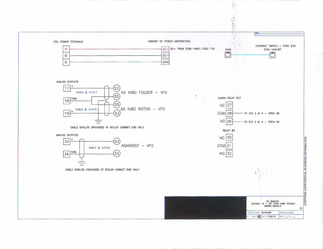
STA. POWER TERMINALS CABINET DC POWER DISTRIBUTION
~ I ,,, """ ,,, '"" '"" ", ANALOG OUTPUTS
AS INBD FEEDER - VFD
INBD ROTOR - VFD
CABLE SHIELDS GROUNDED AT BOILER CABINET END ONLY
ANALOG OUTPUTS
~-+-r--------~53
CABLE #: K 1 D33 ASAIRDIST - VFD
J34 JCOM I I (55
CABLE SHIELDS GROUNDED AT BOILER CABINET END ONLY
I• ' .. I ·;!•
ETHERNET SWITCH - PORT /11 0 RJ45 STBD CABINET
rr'11 fF1l
ALARM RELAY 'ouT
Nc@J coM§- ro srA 2 & 4 - TERM 2s
NO~ro STA 2 & 4- TERM 29
RELAY #2
Nc§] COM@2_]
No §
~
~ ~ z w 0 ~ z 0 0 w z
r-----------------------------~~
0
z 0 0

STA. POWER TERMINALS CABINET DC POWER DISTRIBUTION
~ ~~r FROM STBD PANEL FUSE F9
ANALOG INPUTS
AFT STBD FURNACE PRESS
CABLE # : 0920
250 OHM AFT STBD FLUE GAS INTO ECONOMIZER
250 OHM CABLE #: KD922
CABLE SHIELDS GROUNDED AT BOILER CABINET END ONLY
AFT STBD UPTAKE PRESS
CABLE # : K0923
250 OHM CABLE SHIELDS GROUNDED AT BOILER CABINET END ONLY
ANALOG OUTPUTS
+
COM CABLE #: K091 7 AS I.D. STEAM CONTROL VALVE POSITIONER
GROUNDED AT BOILER CABINET END ONLY
ETHERNET SWITCH - PORT #9
RJ45 PORT CABINET
rr'11 rF1l
ALARM RELAY OUT
NC 1271 COM§--- TO STA 8 & 10 -TERM 28
NO~TO STA 8 & 10 - TERM 29
RELAY #2
Nc §] COM~ No§
z 0 i= <( ::;;; 0:: 0 u_
~ (f) (f) w z Ui ::l <D -' <(
i= z w Cl u: z 0 ()
(f)
z ~ z 0 ()
' 0

rn ~ OC+ ffiO. ~oem<e ~' n
AFT STBD SUPERHEAT PRESS - CONTROL
CABLE #: K0720
250 OHM CABLE #: K0722 AFT STBD DRUM PRESS - CONTROL
250 OHM
'-----j CABLE SHIELDS GROUNDED AT CABINET END ONLY
AFT STBD DRUM PRESS - IND
CABLE 6: K0723
250 OHM
AFT STBD SUPERHEAT PRESS - IND
CABLE # : K0741
250 OHM
ETHERNET SWITCH - PORT #7
RJ45 STBO CABINET
~ frl"il
ALARM RELAY OUT
Nc@J COM~ TO STA 6 & B- TERM 2B
NO §----- TO STA 6 & B - TERM 29
RELAY #2
NC~ COM~ No§]
0
z 0
~ ::;; a:: 0 u. z

... STA. POWER TERMINALS CABINET DC POWER DISTRIBUTION
rn ; ""''" ,ffiO
PANEL FUSE F1 1
ANALOG INPUT UNIVERSAL #1
- TI131
REF. JCT
ANALOG OUTPUTS
AS OTBD FEEDER - VFD
OTBD ROTOR - VFD
CABLE SHIELDS GROUNDED AT BOILER CABINET END ONLY
ETHERNET SWITCH - PORT # 11
RJ45 STBD CABINET
fFi1 ~
ALARM RELAY OUT
Nc@J COM~ TO STA 10 & 12- TERM 26
NO~To STA 10 & 12- TERM 29
RELAY #2
Nc§] coM@2]
No§
I
SS BADGER STATION 11 - AfT STBD OTBD FEEDER
WIRING DETAILS
OOAWING Nti'IIER
'iiEET _ OI' _
z 0
~ ::;;; 0:: 0 u.. ~ Cf) Cf) w z Ui ::::l ttl ---' <.:: i= z w 0 u: z 0 u en z ~ z 0 u
I
0

STA. POWER TERMINALS CABINET DC POWER DISTRIBUTION
rn ~ OC+ mo. "" em<C ""' m
ANALOG INPUTS
+ FWD PORT DRUM LEVEL
CABLE H: K2420
250 OHM + FWD PORT STEAM FLOW
250 OHM CABLE 1: K2422
CABLE SHIELDS GROUNDED AT BOILER CABINET END ONLY
ANALOG OUTPUTS
CABLE H: K2417 FWD PORT FEEDWATER VALVE POSITIONER
CABLE SHIELDS GROUNDED AT BOILER CABINET END ONLY
ETHERNET SWITCH - PORT #12 RJ45 PORT CABINET
~ fi"''"il
ALARM RELAY OUT
Nc@J COM~ TO STA 23 - TERM 28
NO~ TO STA 23 - TERM 29
RELAY #2
NC~ COM@2J
No§]
0
(/) (/) UJ z iii :::> Ill ..J ~ 1-z UJ Cl u::
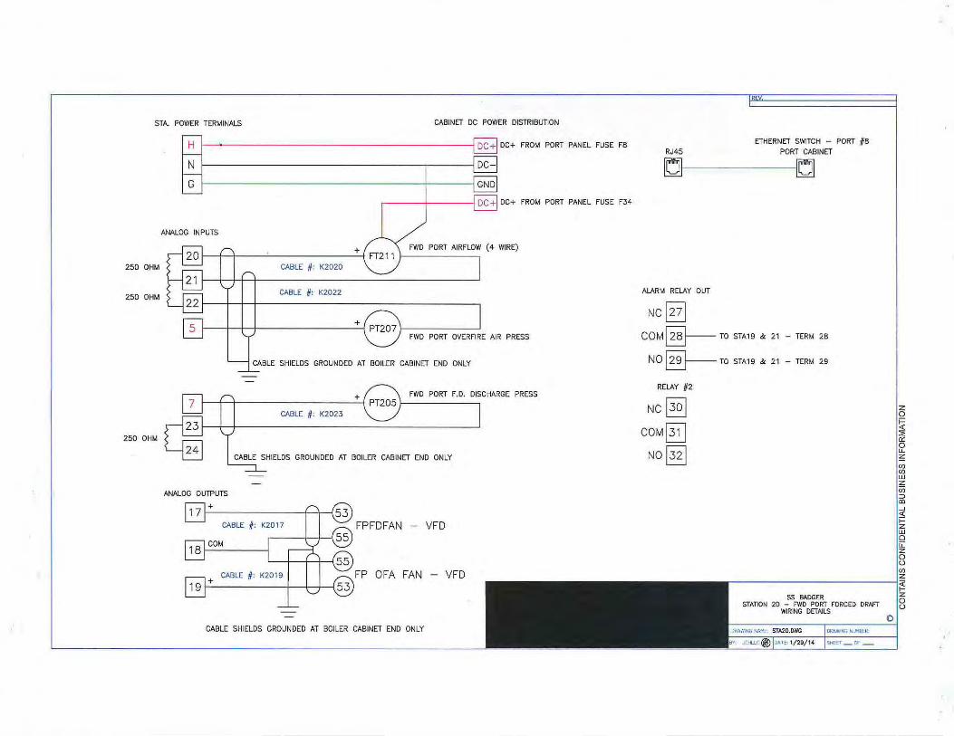
STA. POWER TERMINALS CABINET DC POWER DISTRIBUTION
FROM PORT PANEL FUSE FB
FROM PORT PANEL FUSE F.34
ANALOG INPUTS
+ FWD PORT AIRFLOW (4 WIRE)
250 OHM CABLE #: K2020
250 OHM CABLE #: K2022
+
FWD PORT OVERFIRE AIR PRESS
CABLE SHIELDS GROUNDED AT BOILER CABINET END ONLY
+ FWD PORT F.D. DISCHARGE PRESS
CABLE #: K202.3
250 OHM
ANALOG OUTPUTS
FPFDFAN - VFD
OFA FAN - VFD
CABLE SHIELDS GROUNDED AT BOILER CABINET END ONLY
ETHERNET SWITCH - PORT #B RJ45 PORT CABINET
r'1l frAil
ALARM RELAY OUT
NC~ COM§- TO STA19 & 21 - TERM 2B
NO§-TO STA19 & 21 - TERM 29
RELAY #2
Nc§] COM@2J
No§
z 0
~ ::;: 0:: 0 IJ._
~ en en w z Ui ::J aJ -' 4: i= z w 0 u:: z 0 0 Cl) z ~ z 0 0
I
0

STA. POWER TERMINALS CABINET DC POWER DISTRIBUTION
~ ~ OC< '"" '"' "'"" '"' EW
G GND
ANALOG OUTPUTS
FP INBD FEEDER - VFD
INBD ROTOR - VFD
CABLE SHIELDS GROUNDED AT BOILER CABINET END ONLY
ANALOG OUTPUTS
~-+~--------~53
CABLE #: K2233 FPAIRDIST - VFD
I 55
CABLE SHIELDS GROUNDED AT BOILER CABINET END ONLY
ETHERNET SWITCH - PORT # 1 0 RJ45 PORT CABINET
[OJ ~
ALARM RELAY OUT
NC~ COM~ TO STA21 & 23 - TERM 28
NO§---- TO STA21 & 23 - TERM 29
RELAY H2
Ncj3o l coM@2] NO§:}
55 BADGER STATION 22 - FWD PORT INBD FEEDER
WIRING DETAILS
~.ANI"krllilot"':- Df".l.loMi~-
~~l-~ -- -- - --- --- -
'z 0
~ :::; ~ 0 u. ~ (f) (f) w z iii :::> al ...J < i= z w 0 u:: z 0 u (f) z
~ z 0 u
I
0

STA. POWER TERMINALS CABIN,ET OC POWER DISTRIBUTION
m 1". FROM PORT PANEL FUSE F9
ANALOG INPUTS
FWD PORT FURNACE PRESS
CABLE #: K2120
250 OHM FWD PORT FLUE GAS INTO ECONOMIZER
250 OHM CABLE # : K2122
CABLE SHIELDS GROUNDED AT BOILER CABINET END ONL '1:
+ FWD PORT UPTAKE PRESS
CABLE #: K2123
250 OHM CABLE SHIELDS GROUNDED AT BOILER CABINET END ONLY
ANALOG OUTPUTS
+
COM CABLE #: K2117 FP I. D. STEAM CONTROL VALVE POSITIONER
CABLE SHIELDS GROUNDED AT BOILER CABINET END ONLY
ETHERNET SWITCH - PORT #9
RJ45 PORT CABINET
frM'"il ~
ALARM RELAY OUT
NC [E) COM§----- TO STA20 & 22 - TERM 28
NO§---- TO STA20 & 22 - TERM 29
RELAY #2
Nc§:j coM@:D
No§
0

~ IOCH~eo~ema ,=n
FWD PORT SUPERHEAT PRESS - CONTROL
CABLE #: K1920
250 OHM FWO PORT DRUM PRESS - CONTROL
CABLE /1: K1922
250 OHM
CABLE SHIELDS GROUNDED AT CABINET END ONLY
FWD PORT DRUM PRESS - IND
CABLE II: K1923
250 OHM
+ FWD PORT SUPERHEAT PRESS - IND
CABLE #: K1941
250 OHM
ETHERNET SWITCH - PORT #7 RJ45 PORT CABINET
rr-11 rr""il
ALARM RELAY OUT
Nc@J coM§-To sTA1s & 20 - TERM 2s
NO~ TO STA18 & 20 - TERM 29
RELAY H2
Nc§] COM~
NO 1321
0

STA. POWER TERMINALS CABINET DC POWER DISTRIBUTION rn I OC+ ,,. ,.,. '"" ,,, ,,
ANALOG OUTPUTS
FP OTBD FEEDER - VFD
OTBD ROTOR - VFD
CABLE SHIELDS GROUNDED AT BOILER CABINET END ONLY
ETHERNET SWITCH - PORT #11 RJ45 STBD CABINET
r-11 rr-11
ALARM RELAY OUT
Nc @J COM§----- TO STA 22 & 24 - TERM 28
NO~To STA 22 & 24- TERM 29
RELAY 1/2
NC§:j COM~
No §]
z 0
~ a: 0 LL
~ (/) (/) w z iii ::::> co --' :=; 1-z w a u: z 0 (.)
(/) z
.-----------------------------~~
------
SS BADGER STATION 23 - FWO PORT OTBD FEEDER
WIRING DETAILS
DRAA'•NG Nl..t'I)€R
'ioii:E'T _ Cfo _
0
z 0 (.)

STA. POWER TERMINALS CABINET DC POWER DISTRIBUTION
~ ~ OC+ "'" STilD """ '"" "
ANALOG INPUTS
+ fWD STBD DRUM LEVEL
CABLE N: K0120
250 OHM + fWD STBD STEAM FLOW
250 OHM CABLE N: K0122
L------1 CABLE SHIELDS GROUNDED AT BOILER CABINET END ONLY
ANALOG OUTPUTS
CABLE #: K0117 fWD STBD FEEDWATER VALVE POSITIONER
CABLE SHIELDS GROUNDED AT BOILER CABINET END ONLY
ETHERNET SWITCH - PORT # 1 RJ45 STBD CABINET
rr'1l jFI"j]
ALARM RELAY OUT
NC,271 COM§- TO STA 2- TERM 28
NO§-- TO STA 2 - TERM 29
RELAY #2
Nc§] COM @2J
No§
~ z r---------------1~
0
z 0 u

FWD STBD FD:FS AIR Page 1 of 1
~
- · o, .,., I ~ ri-F-t: E SETPT I ~ SPLJM ~: ]~ I ~~·~ l.~-A-1
AIR FLOW
I OUTPUT > 25% - TRUE (PAF)I
----i\tli~T ~
~,.ro noJ ROUTJ c
'"'
TO F.D. VANES I
f A!Jl p 0 1 :~04 AOol ~~ ~::; AOl-f~ I I ~t I .... OlA® Y ~ AINl ~~~~; I Ill ~q PIP ~== I ~A06 ~ >JM :ilt=
30961 . .,
f ORRECTED AIR FLOW TO FUEL FEEDER!
II ~ ~~~ AATIO ~~ L- ~:11 :- ALARM ti ~~ ... L ~-4
I F.D. FAN RUNNING II I II G A "i' Non o']"' -~-:t~ ORl o! t~ '-----------------1--f---- '
I I.D.IN AUroJ
Wednesday, January 1 5 , 201 4
1" NOD OL}'''
8:45:00 AM
>TE: IFF D FAN IS NOT RUNNING OR I D CONTROL. NOT IN AUTO,F D STAYS IN STANDBY SYNCWrm
OUTPUT OF ZERO
CONTAINS CONFIDENTIAL BUSINESS INFORMATION
' __ ,,, -- U< - Cl.
-->..:•::.L __ _,
I NO., k.EVlSlON I BY IAPP'OI DATE I COMPANY:
CUSTOMER:
I I I I I I DRAW~ DATE I TITLE: ss BADGER JCHLL 1(14/1-' FWD ST~~:.:R~~ FLOW
APl,'D DATE
DRWGNO.:

\
STA. POWER TERMINALS CABINET DC POWER DISTRIBUTION
FROM STBD PANEL FUSE FS
FROM STBD PANEL fUSE f16
ANALOG INPUTS
FWD PORT AIRFLOW ( 4 WIRE)
250 OHM CABLE #: K0520
250 OHM CABLE #: K0522
FWD PORT OVERFIRE AIR PRESS
CABLE SHIELDS GROUNDED AT BOILER CABINET END ONLY
FWD PORT f.D. DISCHARGE PRESS
CABLE f: K052.3
250 OHM
ANALOG OUTPUTS
FSFDFAN - VFD
FS OFA FAN - VFD
CABLE SHIELDS GROUNDED AT BOILER CABINET END ONLY
ETHERNET SWITCH - PORT #5 RJ45 STBD CABINET
fF'1l "
ALARM RELAY OUT
NC~ CQM§- TO STA 4 & 6- TERM 28
NO§-To sTA 4 & 6- TERM 29
RELAY 12
NC~ COM@2J
NO @3]
0
< ::;; 0:: 0 u_ z en en w z (jj ~ al ...J
~

STA. POWER TERMINALS CABINET DC POWER DISTRIBUTION
~ ~ 00+ F""" '"" P>NEC FUSE FJ
ANALOG OUTPUTS
FS INBD FEEDER - VFD
INBD ROTOR - VFD
CABLE SHIELDS GROUNDED AT BOILER CABINET END ONLY
ANALOG OUTPUTS
r--+~--------~53
CABLE #: KD333 FSAIRDIST - VFD
1341COM I I (55
CABLE SHIELDS GROUNDED AT BOILER CABINET END ONLY
ETHERNET SWITCH - PORT #3
RJ45 STBD CABINET
rr1l fFl11
ALARM RELAY OUT
NC~ COM~ TO STA 2 & 4- TERM 26
N0§-To STA 2 & 4 - TERM 29
RELAY #2
NC~ COM@2J
No§]
z 0
~ :2 0:: 0 LJ._
~ (f) (f) w z Ui => co __j
<(
i= z w a u:: z 0 (.)
(f) z <(
I§ 0

STA. POWER TERMINALS CABINET DC POWER DISTRIBUTION
~ I'" FROM STBD PANEL FUSE F4
ANALOG INPUTS
FWD STBD FURNACE PRESS
CABLE #: K0420
250 OHM FWD STBD FLUE GAS INTO ECONOMIZER
250 OHM CABLE #: K20422
CABLE SHIELDS GROUNDED AT BOILER CABINET END ONLY
FWD STBD UPTAKE PRESS
CABLE #: K0423
250 OHM CABLE SHIELDS GROUNDED AT BOILER CABINET END ONLY
ANALOG OUTPUTS
+
COM CABLE #: KD417 FS I.D. STEAM CONTROL VALVE POSITIONER
CABLE SHIELDS GROUNDED AT BOILER CABINET END ONLY
ETHERNET SWITCH - PORT #4
RJ45 PORT CABINET
rr'1l fF'11
ALARM RELAY OUT
Nc@J COM§-- TO STA 3 & 5 - TERM 28
NO§-To STA 3 & s- TERM 29
RELAY #2
Ncl3o l coM@:D No§
0

~ ~ "' """ "'" '"" "'" "
FWD STBD SUPERHEAT PRESS - CONTROL
CABLE # : K0620
250 OHM CABLE #: K0622 FWD STBD DRUM PRESS - CONTROL
250 OHM
CABLE SHIELDS GROUNDED AT CABINET END ONLY
FWD STBD DRUM PRESS - IND
CABLE # : K0623
250 OHM
FWD STBD SUPERHEAT PRESS - IND
CABLE # : KOS41
25D OHM
ETHERNET SWITCH - PORT #6
RJ45 STBD CABINET
rr"1l ~
ALARM RELAY OUT
Nc@J COM~ TO STA 5 & 7 - TERM 28
NO§----- TO STA 5 & 7 - TERM 29
RELAY # 2
NC~ COM~
NO 1321
~ ~ ~ z w 0 ~ z 0 0 ~ z
r-----------------------------~~
0
z 0 0

STA. POWER TERMINALS CABINET DC POWER DISTRIBUTION
~ ~oc• FROM STBD PANEL FUSE F2
ANALOG OUTPUTS
FS OTBD FEEDER - VFD
OTBD ROTOR - VFD
CABLE SHIELDS GROUNDED AT BOILER CABINET END ONLY
ETHERNET SWITCH - PORT #2 RJ45 STBD CABINET
M fF!'il
ALARM RELAY OUT
NeE) COM§--- TO STA 1 & .3 - TERM 26
NO§--ro STA 1 & J- TERM 29
RELAY #2
NC~ COM[_8
No§ \
55 BADGER STATION 2 - FWD STBD OTBD FEEDER
WIRING DETAILS
tf\t. li f<GJrr.;..l"tilR:
~1!' _ 01- _
'Z 0 i= ~ ::;; D: 0 u. ~ (f) Cl) w z ii5 ::> aJ -' ~ i= z w 0 u:: z 0 (.)
Cl) z ~ z 0 (.)
I
0

Thursday, October 27,2011
SELF- CERTIFICATION
ne & Industrial Control Systems
self-certificate of qualifications as a provider of control rules and requirements ofNFPA, FM,OCSA, USCG, ABS,
is a certified systems integrator and or factory trained for Siemens Energy and ~~~~ Wi)ndlef'NaJ'e , Rockwell Allen Bradley and Modi con hardware and software.
is a member ofSNAME, NFPA, !SA and CSIA (Control Systems Integrators a Preferred Integrator of Systems for Siemens Energy & Automation
(originally Moore Products Company). PRISM systems integrators are formally reviewed, trained, and approved in order to be qualified to Siemens-Moore's, exacting standards for Advanced Process Automation and Control System (APACS) and QUADLOG critical safety systems. The PRISM prograJn was developed in response to increased customers' needs for qualified support services in the disciplines of the industries served. PRISM members must have the training and track record to provide detailed engineering studies, local system integration, software application and configuration, local support and lmowledge ofthe rules and regulations oftheir serviced industry. Members of the Siemens-Moore, Process Automation Solutions, PRISM program are selected, according on their
~~"""~~~~in these areas.
CONTAINS CONFIDENTIAL BUSINESS INFORMATION

I
I
I
I
I I
I I
CONTAINS CONFIDENTIAL BUSINESS INFORMATION
2

• I I I
I I
CONTAINS CONFIDEN~L BUSINESS INFORMATION
Respect
President
3