live centres face drivers
TRANSCRIPT
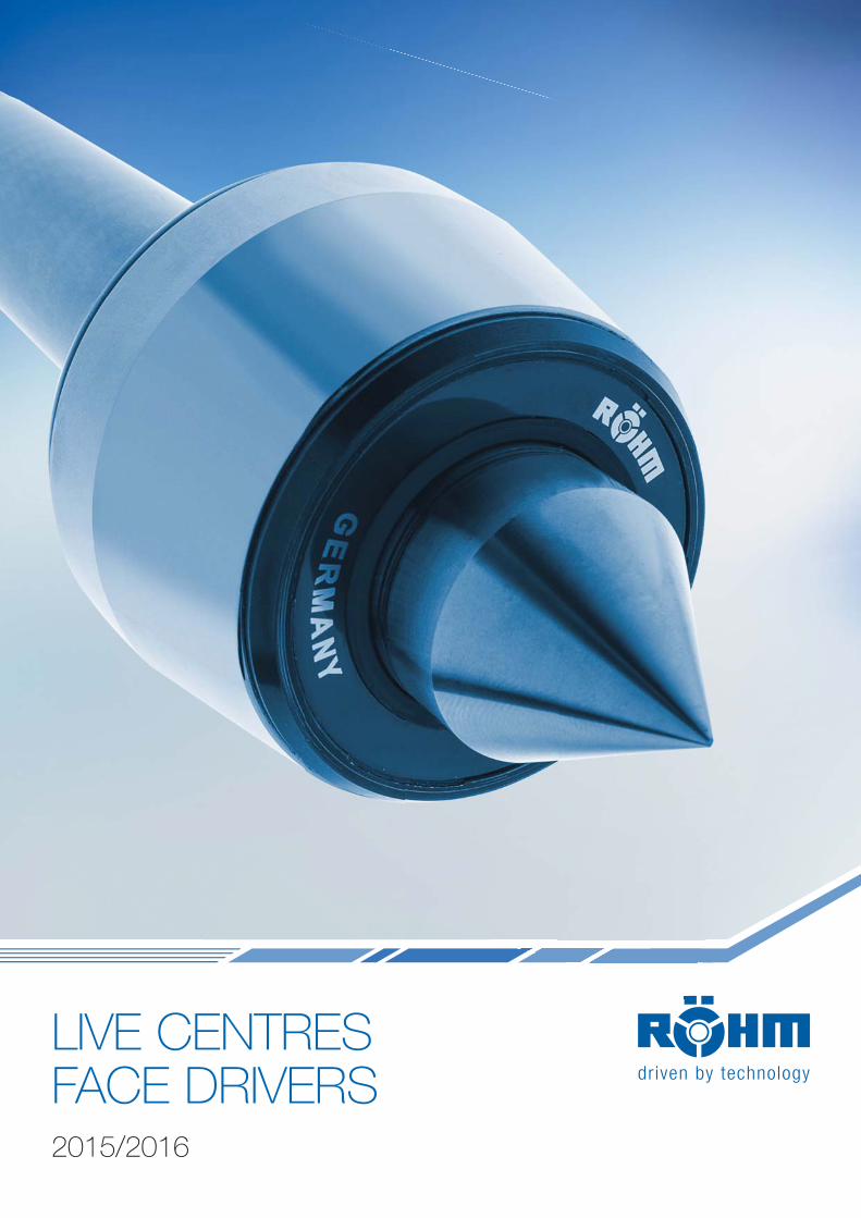
LIVE CENTRESFACE DRIVERS2015/2016
We work for customerswho have a weaknessfor our strengths.
Companies intent on making a difference are obliged to develop constantly as well as deploy
their strengths to the benefit of customers. At RÖHM, we have set ourselves high targets and
are doing our very best to achieve them. This is why we support our customers all over the world
by means of the six performance indicators so typical of RÖHM:
Dynamism
Variety
Security
Partnership
Globality
Innovation
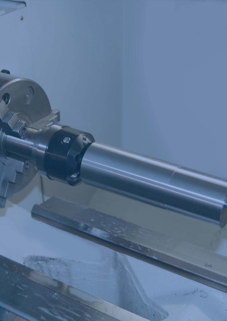
Table of contents
LIVE CENTRES I FACE DRIVERS
Live centresPro - carbide insert 2008Pro - standard design 2010Pro - cylindrical shank 2012Pro - high precision design 2013Pro - extended centre point 2014Pro - profiled, extended centre point 2015Orange Line 2016Heavy - standard design 2017Speed - extended centre point 2019Slim - standard design 2020Slim - extended centre point 2021Slim - profiled, extended centre point 2022Control - standard design 2023Control - extended centre point 2024Flex - interchangeable inserts 2025
Revolving centering taperMZK 2030
Dead centresFZS 2034
Constant face driversCoE 2040CoA 2043CoK 2052
Errors and corrections are reserved!
2002
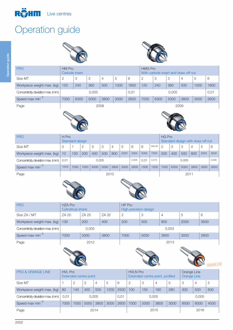
PRO HM Pro
Carbide insert
HMG Pro
With carbide insert and draw-off nut
Size MT 2 3 3 4 5 6 2 3 3 4 5 6
Workpiece weight max. (kg) 120 240 360 500 1000 1800 120 240 360 500 1000 1800
Concentricity deviation max. (mm) 0,005 0,01 0,005 0,01
Speed max min-1 7000 6300 5000 3800 3000 2600 7000 6300 5000 3800 3000 2600
Page 2008 2009
PRO H Pro
Standard design
HG Pro
Standard design with draw-off nut
Size MT 0 1 2 3 3 4 5 6 6 Metr.80 2 3 3 4 5 6
Workpiece weight max. (kg) 10 100 200 400 500 800 2000 3500 5000 7500 200 400 500 800 2000 3500
Concentricity deviation max. (mm) 0,01 0,005 0,008 0,01 0,015 0,005 0,008
Speed max min-1 15000 7000 7000 6300 5000 3800 3000 2600 1500 1500 7000 6300 5000 3800 3000 2600
Page 2010 2011
PRO HZA Pro
Cylindrical shank
HP Pro
High precision design
Size ZA / MT ZA 20 ZA 25 ZA 32 2 3 4 5 6
Workpiece weight max. (kg) 130 200 400 200 500 800 2000 3500
Concentricity deviation max. (mm) 0,005 0,003
Speed max min-1 7000 5000 3800 7000 5000 3800 3000 2600
Page 2012 2013
PRO & ORANGE LINE HVL Pro
Extended centre point
HVLN Pro
Extended centre point, profiled
Orange Line
Orange Line
Size MT 1 2 3 4 5 6 2 3 4 5 3 4 5
Workpiece weight max. (kg) 80 140 400 500 1200 2500 100 150 180 280 300 500 630
Concentricity deviation max. (mm) 0,01 0,005 0,01 0,005 0,005
Speed max min-1 7000 7000 5000 3800 3000 2600 7000 5000 3800 3000 8500 6000 4500
Page 2014 2015 2016
ORANGE LINE
Op
erat
ion
gui
de
Live centres
Operation guide
2003
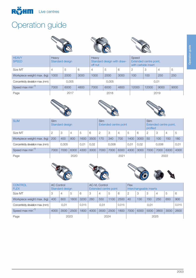
HEAVY
SPEED
Heavy
Standard design
Heavy
Standard design with draw-
off nut
Speed
Extended centre point,
with carbide insert
Size MT 4 5 6 4 5 6 2 3 4 5
Workpiece weight max. (kg) 1000 2000 3000 1000 2000 3000 100 100 250 250
Concentricity deviation max. (mm) 0,005 0,005 0,01
Speed max min-1 7000 6000 4800 7000 6000 4800 12000 12000 9000 9000
Page 2017 2018 2019
SLIM Slim
Standard design
Slim
Extended centre point
Slim
Extended centre point,
profiled
Size MT 2 3 4 5 6 2 3 4 5 6 2 3 4 5
Workpiece weight max. (kg) 200 400 800 1600 3500 170 340 700 1400 3000 50 100 150 180
Concentricity deviation max. (mm) 0,005 0,01 0,02 0,008 0,01 0,02 0,008 0,01
Speed max min-1 7000 7000 6300 4300 3000 7000 7000 6300 4300 3000 7000 7000 6300 4300
Page 2020 2021 2022
CONTROL
FLEX
AC Control
Standard design
AC-VL Control
Extended centre point
Flex
Interchangeable inserts
Size MT 3 4 5 6 3 4 5 6 2 3 3 4 5 6
Workpiece weight max. (kg) 400 800 1600 3200 260 550 1100 2500 40 130 150 250 650 900
Concentricity deviation max. (mm) 0,01 0,015 0,01 0,015 0,01 0,015
Speed max min-1 4000 3500 2500 1800 4000 3500 2500 1800 7000 6300 5000 3800 3000 2600
Page 2023 2024 2025
Op
erat
ion
gui
de
Live centres
Operation guide
2004
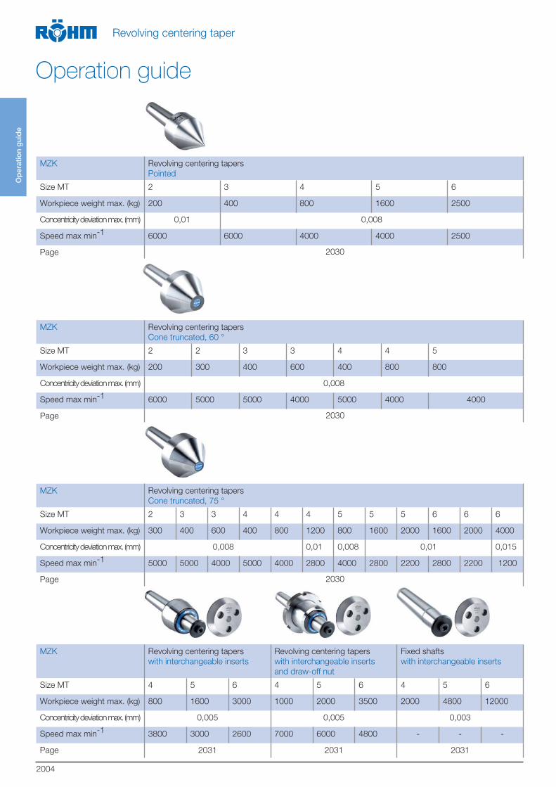
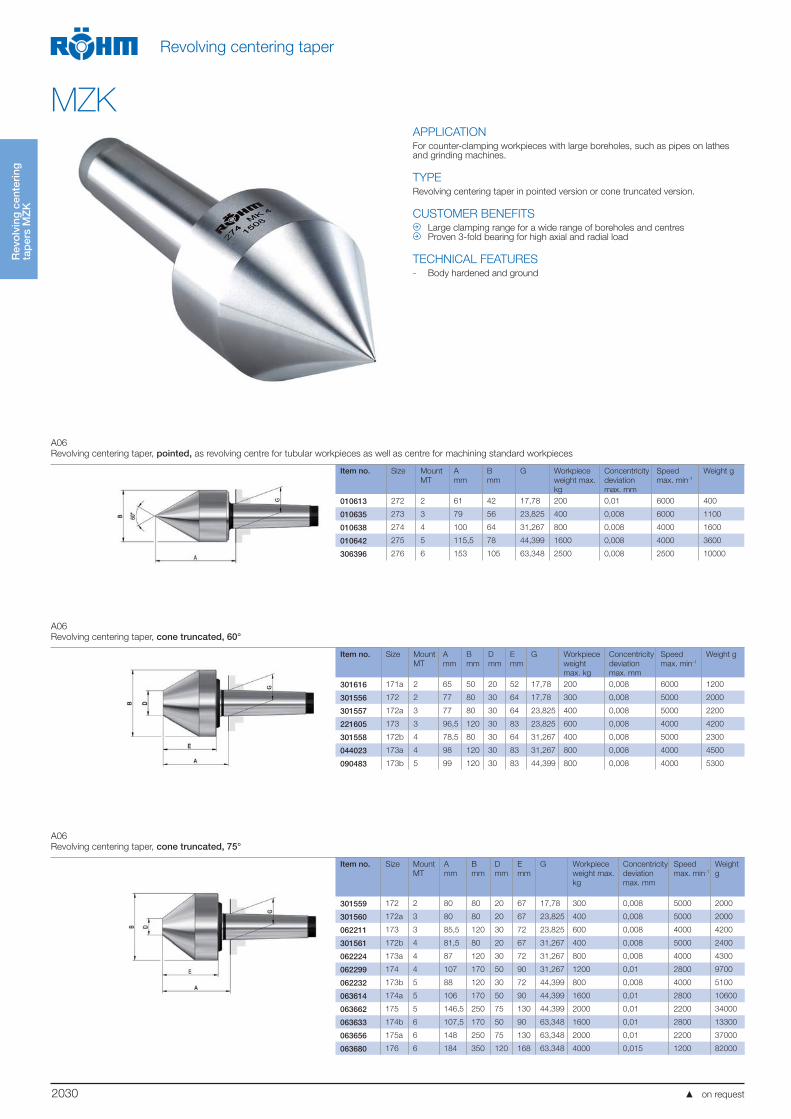
MZK Revolving centering tapers
Pointed
Size MT 2 3 4 5 6
Workpiece weight max. (kg) 200 400 800 1600 2500
Concentricity deviation max. (mm) 0,01 0,008
Speed max min-1 6000 6000 4000 4000 2500
Page 2030
MZK Revolving centering tapers
Cone truncated, 60 °
Size MT 2 2 3 3 4 4 5
Workpiece weight max. (kg) 200 300 400 600 400 800 800
Concentricity deviation max. (mm) 0,008
Speed max min-1 6000 5000 5000 4000 5000 4000 4000
Page 2030
MZK Revolving centering tapers
Cone truncated, 75 °
Size MT 2 3 3 4 4 4 5 5 5 6 6 6
Workpiece weight max. (kg) 300 400 600 400 800 1200 800 1600 2000 1600 2000 4000
Concentricity deviation max. (mm) 0,008 0,01 0,008 0,01 0,015
Speed max min-1 5000 5000 4000 5000 4000 2800 4000 2800 2200 2800 2200 1200
Page 2030
MZK Revolving centering tapers
with interchangeable inserts
Revolving centering tapers
with interchangeable inserts
and draw-off nut
Fixed shafts
with interchangeable inserts
Size MT 4 5 6 4 5 6 4 5 6
Workpiece weight max. (kg) 800 1600 3000 1000 2000 3500 2000 4800 12000
Concentricity deviation max. (mm) 0,005 0,005 0,003
Speed max min-1 3800 3000 2600 7000 6000 4800 - - -
Page 2031 2031 2031
Op
erat
ion
gui
de
Revolving centering taper
Operation guide

2005
FZS Dead centres
Full point
Size MT 0 1 2 3 4 5 6
Concentricity deviation max. (mm) 0,005
Page 2034
FZS Dead centres
With full carbide tip
Dead centres
Full point, carbide insert and regrinding line
Size MT 2 3 4 5 2 3 4 5
Concentricity deviation max. (mm) 0,005 0,005
Page 2034 2034
FZS Dead centres
Half point with carbide insert
Dead centres
Half point
Size MT 2 3 4 5 2 3 4 5
Concentricity deviation max. (mm) 0,005 0,01
Page 2035 2035
FZS Dead centres
Full point, draw-off nut and SW
Dead centres
Full point, draw-off nut, SW and extended point
Size MT 3 4 5 6 3 4 5 6
Concentricity deviation max. (mm) 0,005 0,005
Page 2035 2035
Dead centres in high precision design on request.
Op
erat
ion
gui
de
Dead centres
Operation guide
2006
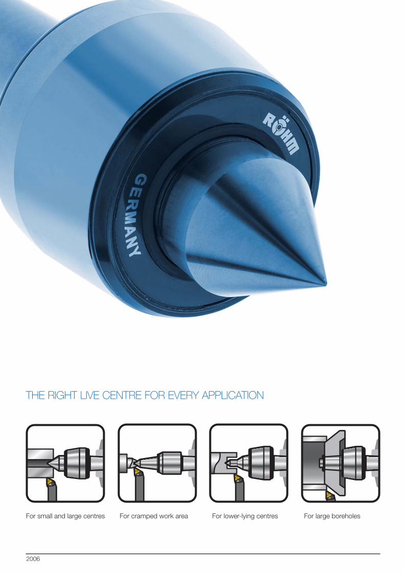
THE RIGHT LIVE CENTRE FOR EVERY APPLICATION
For small and large centres For cramped work area For lower-lying centres For large boreholes
2007
LIVE CENTRES
ADVANTAGES AT A GLANCE
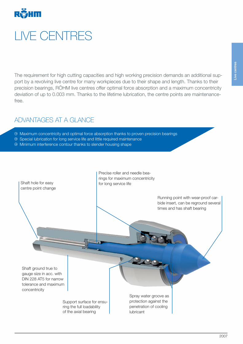
The requirement for high cutting capacities and high working precision demands an additional sup-
port by a revolving live centre for many workpieces due to their shape and length. Thanks to their
precision bearings, RÖHM live centres offer optimal force absorption and a maximum concentricity
deviation of up to 0.003 mm. Thanks to the lifetime lubrication, the centre points are maintenance-
free.
Shaft ground true to
gauge size in acc. with
DIN 228 AT5 for narrow
tolerance and maximum
concentricity
Precise roller and needle bea-
rings for maximum concentricity
for long service life
Running point with wear-proof car-
bide insert, can be reground several
times and has shaft bearing
Maximum concentricity and optimal force absorption thanks to proven precision bearings
Special lubrication for long service life and little required maintenance
Minimum interference contour thanks to slender housing shape
Support surface for ensu-
ring the full loadability
of the axial bearing
Spray water groove as
protection against the
penetration of cooling
lubricant
Shaft hole for easy
centre point change
Live
cen
tres
2008
Live
cen
tres
Live centres
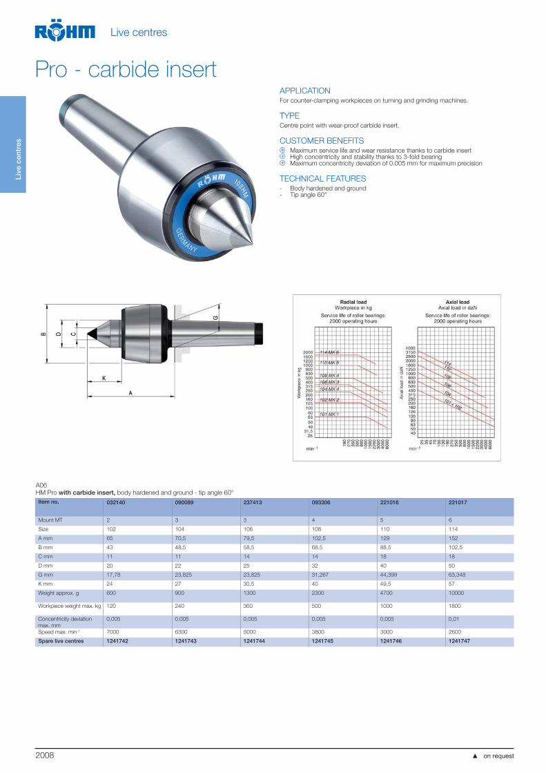
Pro - carbide insertAPPLICATIONFor counter-clamping workpieces on turning and grinding machines.
TYPECentre point with wear-proof carbide insert.
CUSTOMER BENEFITS Maximum service life and wear resistance thanks to carbide insert High concentricity and stability thanks to 3-fold bearing Maximum concentricity deviation of 0.005 mm for maximum precision
TECHNICAL FEATURES- Body hardened and ground- Tip angle 60°
A06
HM Pro with carbide insert, body hardened and ground - tip angle 60°
Item no. 032140 090089 237413 093306 221016 221017
Mount MT 2 3 3 4 5 6
Size 102 104 106 108 110 114
A mm 65 70,5 79,5 102,5 129 152
B mm 43 48,5 58,5 68,5 88,5 102,5
C mm 11 11 14 14 18 18
D mm 20 22 25 32 40 50
G mm 17,78 23,825 23,825 31,267 44,399 63,348
K mm 24 27 30,5 40 49,5 57
Weight approx. g 600 900 1300 2300 4700 10000
Workpiece weight max. kg 120 240 360 500 1000 1800
Concentricity deviation
max. mm
0,005 0,005 0,005 0,005 0,005 0,01
Speed max. min-1 7000 6300 5000 3800 3000 2600
Spare live centres 1241742 1241743 1241744 1241745 1241746 1241747

2009
Live
cen
tres
Live centres
Pro - carbide insertAPPLICATIONFor counter-clamping workpieces on turning and grinding machines.
TYPECentre point with wear-proof carbide insert.With draw-off nut.
CUSTOMER BENEFITS Maximum service life and wear resistance thanks to carbide insert High concentricity and stability thanks to 3-fold bearing Maximum concentricity deviation of 0.005 mm for maximum precision
TECHNICAL FEATURES- Body hardened and ground- Tip angle 60°
A06
HMG Pro with draw-off nut and carbide insert, body hardened and ground - tip angle 60°
Item no. 221021 221022 221023 221024 221025 221026
Mount MT 2 3 3 4 5 6
Size 102 104 106 108 110 114
A mm 65 70,5 79,5 102,5 129 152
B mm 45 50 60 70 90 105
C mm 11 11 14 14 18 18
D mm 20 22 25 32 40 50
G mm 17,78 23,825 23,825 31,265 44,399 63,348
K mm 24 27 30,5 40 49,5 57
M mm 56 62 74 82 105 120
Weight approx. g 600 1000 1400 2400 5200 10500
Workpiece weight max. kg 120 240 360 500 1000 1800
Concentricity deviation
max. mm
0,005 0,005 0,005 0,005 0,005 0,01
Speed max. min-1 7000 6300 5000 3800 3000 2600
Spare live centres 1241742 1241743 1241744 1241745 1241746 1241747
2010
Live
cen
tres
Live centres
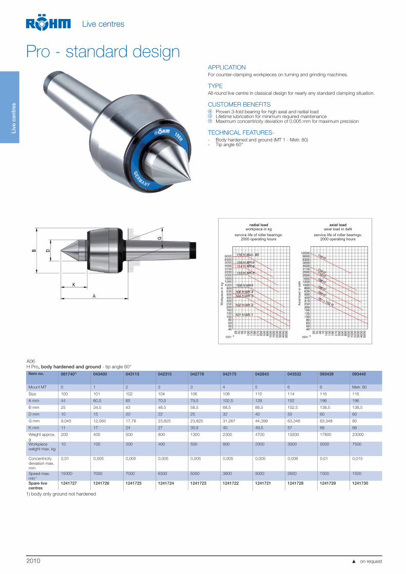
APPLICATIONFor counter-clamping workpieces on turning and grinding machines.
TYPEAll-round live centre in classical design for nearly any standard clamping situation.
CUSTOMER BENEFITS Proven 3-fold bearing for high axial and radial load Lifetime lubrication for minimum required maintenance Maximum concentricity deviation of 0.005 mm for maximum precision
TECHNICAL FEATURES-- Body hardened and ground (MT 1 - Metr. 80)- Tip angle 60°
radial loadworkpiece in kg
service life of roller bearings:2000 operating hours
axial loadaxial load in daN
service life of roller bearings:2000 operating hours
Wor
kpie
cein
kg
Axi
allo
adin
daN
A06
H Pro, body hardened and ground - tip angle 60°
Item no. 0617401) 043400 043115 042315 042776 042175 042843 043532 093439 093440
Mount MT 0 1 2 3 3 4 5 6 6 Metr. 80
Size 100 101 102 104 106 108 110 114 116 116
A mm 44 60,5 65 70,5 79,5 102,5 129 152 196 196
B mm 25 34,5 43 48,5 58,5 68,5 88,5 102,5 138,5 138,5
D mm 10 15 20 22 25 32 40 50 60 60
G mm 9,045 12,065 17,78 23,825 23,825 31,267 44,399 63,348 63,348 80
K mm 11 17 24 27 30,5 40 49,5 57 66 66
Weight approx.
g
200 400 500 800 1300 2300 4700 10200 17800 23000
Workpiece
weight max. kg
10 100 200 400 500 800 2000 3500 5000 7500
Concentricity
deviation max.
mm
0,01 0,005 0,005 0,005 0,005 0,005 0,005 0,008 0,01 0,015
Speed max.
min-1
15000 7000 7000 6300 5000 3800 3000 2600 1500 1500
Spare live centres
1241727 1241726 1241725 1241724 1241723 1241722 1241721 1241728 1241729 1241730
1) body only ground not hardened
Pro - standard design
on request
2011
Live
cen
tres
Live centres
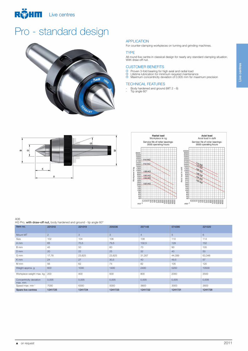
APPLICATIONFor counter-clamping workpieces on turning and grinding machines.
TYPEAll-round live centre in classical design for nearly any standard clamping situation.With draw-off nut.
CUSTOMER BENEFITS Proven 3-fold bearing for high axial and radial load Lifetime lubrication for minimum required maintenance Maximum concentricity deviation of 0.005 mm for maximum precision
TECHNICAL FEATURES- Body hardened and ground (MT 2 - 6)- Tip angle 60°
A06
HG Pro, with draw-off nut, body hardened and ground - tip angle 60°
Item no. 221018 221019 205036 207148 074390 221020
Mount MT 2 3 3 4 5 6
Size 102 104 106 108 110 114
A mm 65 70,5 79,5 102,5 129 152
B mm 45 50 60 70 90 105
D mm 20 22 25 32 40 50
G mm 17,78 23,825 23,825 31,267 44,399 63,348
K mm 24 27 30,5 40 49,5 57
M mm 56 62 74 82 105 120
Weight approx. g 600 1000 1400 2400 5200 10500
Workpiece weight max. kg 200 400 500 800 2000 3500
Concentricity deviation
max. mm
0,005 0,005 0,005 0,005 0,005 0,008
Speed max. min-1 7000 6300 5000 3800 3000 2600
Spare live centres 1241725 1241724 1241723 1241722 1241721 1241728
Pro - standard design
on request
2012
Live
cen
tres
Live centres
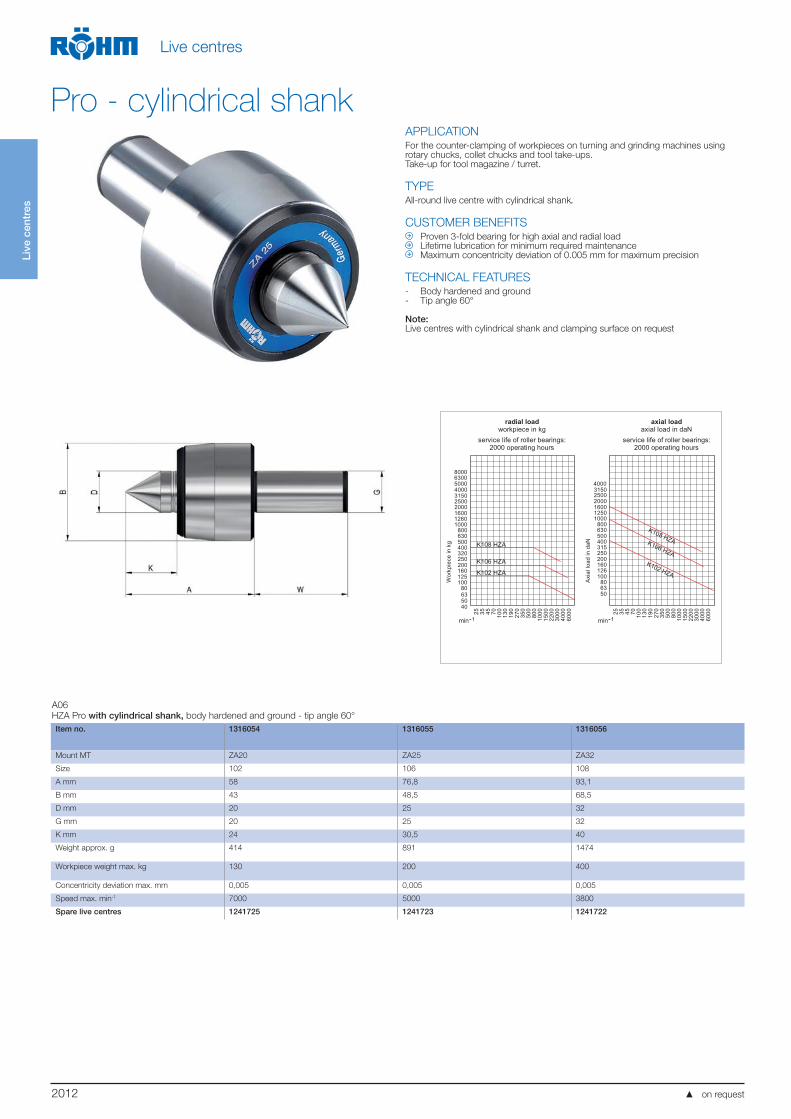
APPLICATIONFor the counter-clamping of workpieces on turning and grinding machines using rotary chucks, collet chucks and tool take-ups.Take-up for tool magazine / turret.
TYPEAll-round live centre with cylindrical shank.
CUSTOMER BENEFITS Proven 3-fold bearing for high axial and radial load Lifetime lubrication for minimum required maintenance Maximum concentricity deviation of 0.005 mm for maximum precision
TECHNICAL FEATURES- Body hardened and ground- Tip angle 60°
Note:Live centres with cylindrical shank and clamping surface on request
radial loadworkpiece in kg
service life of roller bearings:2000 operating hours
axial loadaxial load in daN
service life of roller bearings:2000 operating hours
4000315025002000160012601000
800630500400320250200160125100
80
K102 HZA
4000315025002000160012501000
800630500400315250200160126100
806350
25 35 45 70 100
130
190
270
350
500
800
1000
1500
2200
3000
4000
6000
min--1 min--1
Wor
kpie
cein
kg
Axi
allo
adin
daN
5000
K108 HZA
25 35 45 70 100
130
190
270
350
500
800
1000
1500
2200
3000
4000
6000
K102 HZA
K106 HZA
K108 HZA
635040
63008000
K106 HZA
A06
HZA Pro with cylindrical shank, body hardened and ground - tip angle 60°
Item no. 1316054 1316055 1316056
Mount MT ZA20 ZA25 ZA32
Size 102 106 108
A mm 58 76,8 93,1
B mm 43 48,5 68,5
D mm 20 25 32
G mm 20 25 32
K mm 24 30,5 40
Weight approx. g 414 891 1474
Workpiece weight max. kg 130 200 400
Concentricity deviation max. mm 0,005 0,005 0,005
Speed max. min-1 7000 5000 3800
Spare live centres 1241725 1241723 1241722
Pro - cylindrical shank
on request
2013
Live
cen
tres
Live centres
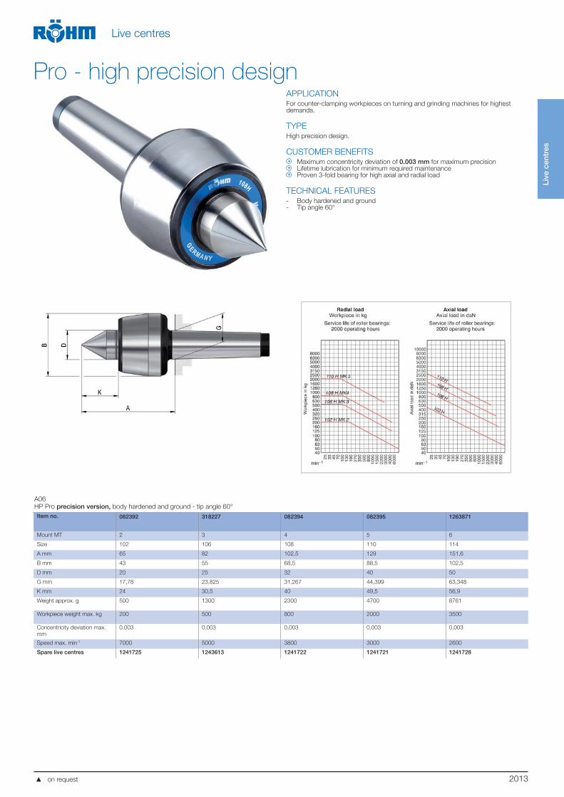
APPLICATIONFor counter-clamping workpieces on turning and grinding machines for highest demands.
TYPEHigh precision design.
CUSTOMER BENEFITS Maximum concentricity deviation of 0.003 mm for maximum precision Lifetime lubrication for minimum required maintenance Proven 3-fold bearing for high axial and radial load
TECHNICAL FEATURES- Body hardened and ground- Tip angle 60°
A06
HP Pro precision version, body hardened and ground - tip angle 60°
Item no. 082392 318227 082394 082395 1263871
Mount MT 2 3 4 5 6
Size 102 106 108 110 114
A mm 65 82 102,5 129 151,6
B mm 43 55 68,5 88,5 102,5
D mm 20 25 32 40 50
G mm 17,78 23,825 31,267 44,399 63,348
K mm 24 30,5 40 49,5 56,9
Weight approx. g 500 1300 2300 4700 8761
Workpiece weight max. kg 200 500 800 2000 3500
Concentricity deviation max.
mm
0,003 0,003 0,003 0,003 0,003
Speed max. min-1 7000 5000 3800 3000 2600
Spare live centres 1241725 1243613 1241722 1241721 1241728
Pro - high precision design
on request
2014
Live
cen
tres
Live centres
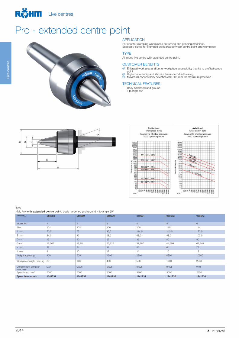
APPLICATIONFor counter-clamping workpieces on turning and grinding machines.Especially suited for cramped work area between centre point and workpiece.
TYPEAll-round live centre with extended centre point.
CUSTOMER BENEFITS Enlarged work area and better workpiece accessibility thanks to profiled centre
point High concentricity and stability thanks to 3-fold bearing Maximum concentricity deviation of 0.005 mm for maximum precision
TECHNICAL FEATURES- Body hardened and ground- Tip angle 60°
A06
HVL Pro with extended centre point, body hardened and ground - tip angle 60°
Item no. 058668 058669 058670 058671 058672 058673
Mount MT 1 2 3 4 5 6
Size 101 102 106 108 110 114
A mm 70,5 75 95,5 114,5 143,5 172,5
B mm 34,5 43 58,5 68,5 88,5 102,5
D mm 15 20 25 32 40 50
G mm 12,065 17,78 23,825 31,267 44,399 63,348
K mm 27 34 47 53 64 78
J mm 9 10 12 14 16 18
Weight approx. g 400 500 1300 2300 4800 10200
Workpiece weight max. kg 80 140 400 500 1200 2500
Concentricity deviation
max. mm
0,01 0,005 0,005 0,005 0,005 0,01
Speed max. min-1 7000 7000 5000 3800 3000 2600
Spare live centres 1241731 1241732 1241733 1241734 1241735 1241736
Pro - extended centre point
on request
2015
Live
cen
tres
Live centres
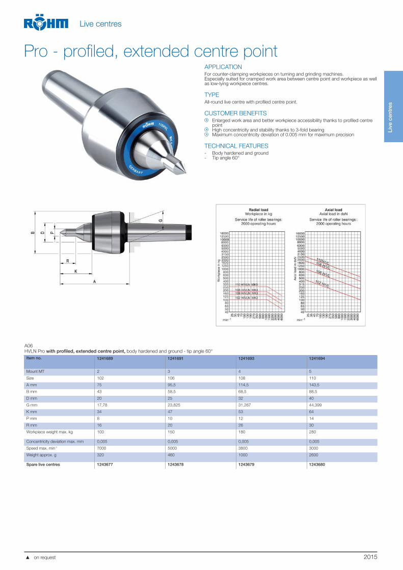
APPLICATIONFor counter-clamping workpieces on turning and grinding machines.Especially suited for cramped work area between centre point and workpiece as well as low-lying workpiece centres.
TYPEAll-round live centre with profiled centre point.
CUSTOMER BENEFITS Enlarged work area and better workpiece accessibility thanks to profiled centre
point High concentricity and stability thanks to 3-fold bearing Maximum concentricity deviation of 0.005 mm for maximum precision
TECHNICAL FEATURES- Body hardened and ground- Tip angle 60°
A06
HVLN Pro with profiled, extended centre point, body hardened and ground - tip angle 60°
Item no. 1241689 1241691 1241693 1241694
Mount MT 2 3 4 5
Size 102 106 108 110
A mm 75 95,5 114,5 143,5
B mm 43 58,5 68,5 88,5
D mm 20 25 32 40
G mm 17,78 23,825 31,267 44,399
K mm 34 47 53 64
P mm 8 10 12 14
R mm 16 20 26 30
Workpiece weight max. kg 100 150 180 280
Concentricity deviation max. mm 0,005 0,005 0,005 0,005
Speed max. min-1 7000 5000 3800 3000
Weight approx. g 320 460 1000 2600
Spare live centres 1243677 1243678 1243679 1243680
Pro - profiled, extended centre point
on request
2016
Live
cen
tres
Live centres
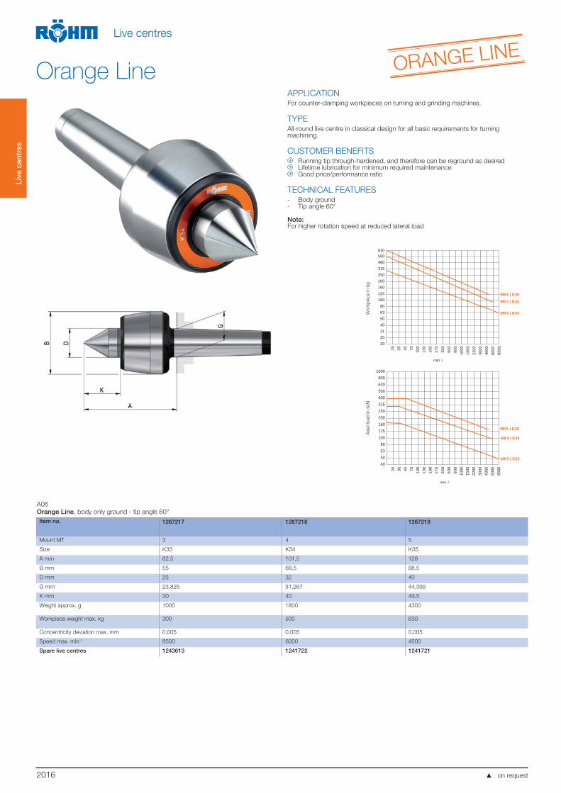
APPLICATIONFor counter-clamping workpieces on turning and grinding machines.
TYPEAll-round live centre in classical design for all basic requirements for turning machining.
CUSTOMER BENEFITS Running tip through-hardened, and therefore can be reground as desired Lifetime lubrication for minimum required maintenance Good price/performance ratio
TECHNICAL FEATURES- Body ground- Tip angle 60°
Note: For higher rotation speed at reduced lateral load
A06
Orange Line, body only ground - tip angle 60°
Item no. 1267217 1267218 1267219
Mount MT 3 4 5
Size K33 K34 K35
A mm 82,5 101,5 128
B mm 55 68,5 88,5
D mm 25 32 40
G mm 23,825 31,267 44,399
K mm 30 40 49,5
Weight approx. g 1000 1800 4300
Workpiece weight max. kg 300 500 630
Concentricity deviation max. mm 0,005 0,005 0,005
Speed max. min-1 8500 6000 4500
Spare live centres 1243613 1241722 1241721
Orange Line ORANGE LINE
on request
25 35 45 70 100
130
190
270
350
500
800
1000
6000
4000
3000
2200
1500
8500
min
20253140506380
100125160200250315400500
Wer
kstü
ckge
wic
ht in
kg
MK5 | K35
MK4 | K34
MK3 | K33
-1
630
25 35 45 70 100
130
190
270
350
500
800
1000
6000
4000
3000
2200
1500
8500
min
40506380
100125160200250315400500630800
1000Ax
ialb
elas
tung
in d
aN
MK5 | K35
MK4 | K34
MK3 | K33
-1
Wo
rkp
iece in k
gA
xia
l lo
ad
in d
aN

2017
Live
cen
tres
Live centres
APPLICATIONFor counter-clamping especially heavy workpieces on turning and grinding machines.Especially suitable for use on NC-machines.
TYPEUniversal version with extended centre point for heavy workpieces.
CUSTOMER BENEFITS Robust 4-fold precision bearing for high speeds as well as high axial and radial
loads Reliable and safe clamping of heavy workpieces Maximum concentricity deviation of 0.005 mm for maximum precision
TECHNICAL FEATURES- Body hardened and ground- Tip angle 60°
Radial loadWorkpiece in kg
Service life of roller bearings:2000 operating hours
Axial loadAxial load in daN
Service life of roller bearings:2000 operating hours
280
355
450
560
710
900
1120
1400
1800
2240
2800
3550
4500
5600
7100
9000 28
035
545
056
071
090
011
2014
0018
0022
4028
0035
5045
0056
0071
0090
00
min--1 min--1
Wor
kpie
cein
kg
Axi
allo
adin
daN
4000
3150
2500
2000
1600
1250
1000
800
630
5000
4000
3150
2500
2000
1600
1250
1000
800
630
500
400
315
424 + 484
425 + 485
426 + 486
424 + 484
425 + 485
426 + 486
A06
Heavy especially for high load at high speeds, body hardened and ground - tip angle 60°
Item no. 303598 303599 301696
Mount MT 4 5 6
Size 424 425 426
A mm 122 150 180
B mm 70 95 120
D mm 32 42 58
G mm 31,267 44,399 63,348
J mm 16 20 26
K mm 44,5 59,5 76
Weight approx. g 2600 5500 11500
Workpiece weight max. kg 1000 2000 3000
Concentricity deviation max. mm 0,005 0,005 0,005
Speed max. min-1 7000 6000 4800
Spare live centres 1241762 1241763 1241764
Heavy - standard design
on request
2018
Live
cen
tres
Live centres
APPLICATIONFor counter-clamping especially heavy workpieces on turning and grinding machines.Especially suitable for use on NC-machines.
TYPEUniversal version with extended centre point for heavy workpieces.With draw-off nut.
CUSTOMER BENEFITS Robust 4-fold precision bearing for high speeds as well as high axial and radial
loads Reliable and safe clamping of heavy workpieces Maximum concentricity deviation of 0.005 mm for maximum precision
TECHNICAL FEATURES- Body hardened and ground- Tip angle 60°
A06
Heavy with draw-off nut, especially for high load at high speeds, body hardened and ground - tip angle 60°
Item no. 304521 304522 304523
Mount MT 4 5 6
Size 484 485 486
A mm 122 150 180
B mm 70 95 120
D mm 32 42 58
G mm 31,267 44,399 63,348
J mm 16 20 26
K mm 44,5 59,5 76
M mm 100 125 155
Weight approx. g 2800 5400 12300
Workpiece weight max. kg 1000 2000 3000
Concentricity deviation max. mm 0,005 0,005 0,005
Speed max. min-1 7000 6000 4800
Spare live centres 1241762 1241763 1241764
Heavy - standard design
on request
2019
Live
cen
tres
Live centres
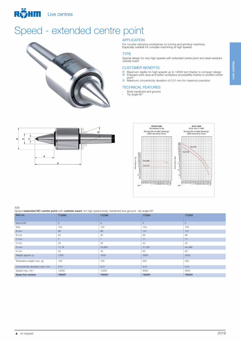
APPLICATIONFor counter-clamping workpieces on turning and grinding machines.Especially suitable for complex machining at high speeds.
TYPESpecial design for very high speeds with extended centre point and wear-resistant carbide insert.
CUSTOMER BENEFITS Maximum rigidity for high speeds up to 12000 rpm thanks to compact design Enlarged work area and better workpiece accessibility thanks to profiled centre
point Maximum concentricity deviation of 0.01 mm for maximum precision
TECHNICAL FEATURES- Body hardened and ground- Tip angle 60°
A06
Speed extended NC-centre point with carbide insert, for high speed body, hardened and ground - tip angle 60°
Item no. 772389 772390 772391 772392
Mount MT 2 3 4 5
Size 752 753 754 755
A mm 99 99 141 141
B mm 45 45 66 66
C mm 7 7 11 11
D mm 20 20 32 32
G mm 17,78 23,825 31,267 44,399
K mm 40 40 63 63
Weight approx. g 1200 1600 2600 5000
Workpiece weight max. kg 100 100 250 250
Concentricity deviation max. mm 0,01 0,01 0,01 0,01
Speed max. min-1 12000 12000 9000 9000
Spare live centres 790267 790267 790291 790291
Speed - extended centre point
on request
2020
Live
cen
tres
Live centres
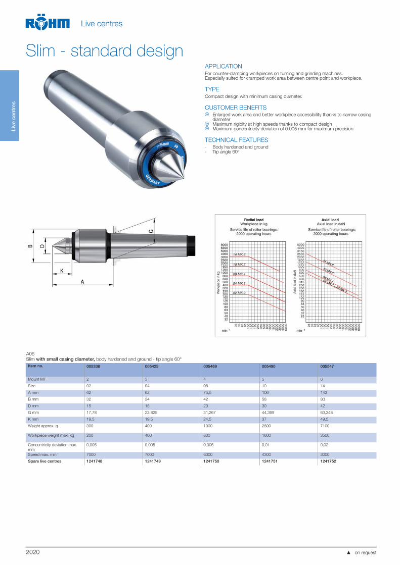
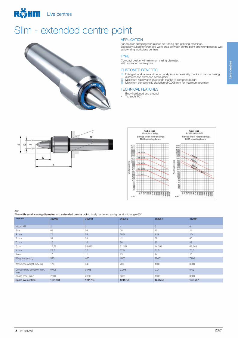
APPLICATIONFor counter-clamping workpieces on turning and grinding machines.Especially suited for cramped work area between centre point and workpiece.
TYPECompact design with minimum casing diameter.
CUSTOMER BENEFITS Enlarged work area and better workpiece accessibility thanks to narrow casing
diameter Maximum rigidity at high speeds thanks to compact design Maximum concentricity deviation of 0.005 mm for maximum precision
TECHNICAL FEATURES- Body hardened and ground- Tip angle 60°
A06
Slim with small casing diameter, body hardened and ground - tip angle 60°
Item no. 005336 005429 005469 005490 005547
Mount MT 2 3 4 5 6
Size 02 04 08 10 14
A mm 62 62 75,5 106 143
B mm 32 34 42 58 80
D mm 15 15 20 30 42
G mm 17,78 23,825 31,267 44,399 63,348
K mm 19,5 19,5 24,5 37 49,5
Weight approx. g 300 400 1000 2600 7100
Workpiece weight max. kg 200 400 800 1600 3500
Concentricity deviation max.
mm
0,005 0,005 0,005 0,01 0,02
Speed max. min-1 7000 7000 6300 4300 3000
Spare live centres 1241748 1241749 1241750 1241751 1241752
Slim - standard design
on request
2021
Live
cen
tres
Live centres
APPLICATIONFor counter-clamping workpieces on turning and grinding machines.Especially suited for cramped work area between centre point and workpiece as well as low-lying workpiece centres.
TYPECompact design with minimum casing diameter.With extended centre point.
CUSTOMER BENEFITS Enlarged work area and better workpiece accessibility thanks to narrow casing
diameter and extended centre point Maximum rigidity at high speeds thanks to compact design Maximum concentricity deviation of 0.008 mm for maximum precision
TECHNICAL FEATURES- Body hardened and ground- Tip angle 60°
A06
Slim with small casing diameter and extended centre point, body hardened and ground - tip angle 60°
Item no. 362080 362081 362082 362083 362084
Mount MT 2 3 4 5 6
Size 02 04 08 10 14
A mm 73 74 88,5 119 164
B mm 32 34 42 58 80
D mm 15 15 20 30 42
G mm 17,78 23,825 31,267 44,399 63,348
K mm 29,5 32 37,5 51,5 70,5
J mm 10 11 13 14 18
Weight approx. g 320 460 1000 2600 7100
Workpiece weight max. kg 170 340 700 1400 3000
Concentricity deviation max.
mm
0,008 0,008 0,008 0,01 0,02
Speed max. min-1 7000 7000 6300 4300 3000
Spare live centres 1241753 1241754 1241755 1241756 1241757
Slim - extended centre point
on request
2022
Live
cen
tres
Live centres
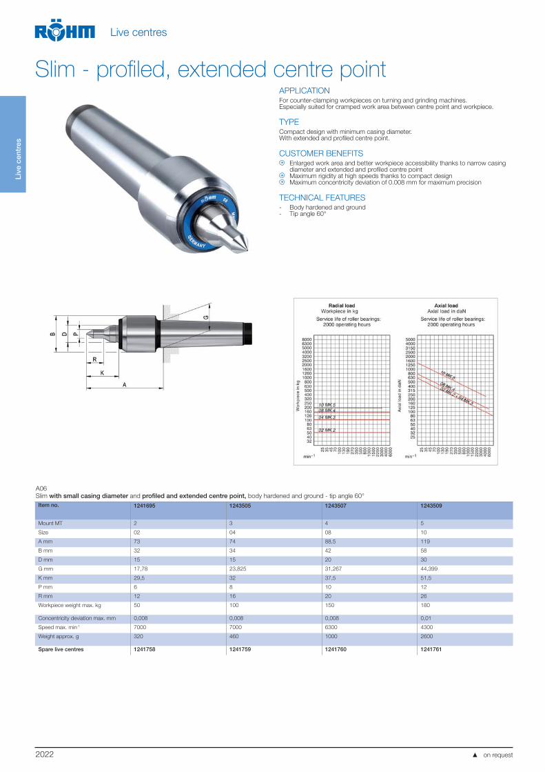
APPLICATIONFor counter-clamping workpieces on turning and grinding machines.Especially suited for cramped work area between centre point and workpiece.
TYPE Compact design with minimum casing diameter.With extended and profiled centre point.
CUSTOMER BENEFITS Enlarged work area and better workpiece accessibility thanks to narrow casing
diameter and extended and profiled centre point Maximum rigidity at high speeds thanks to compact design Maximum concentricity deviation of 0.008 mm for maximum precision
TECHNICAL FEATURES- Body hardened and ground- Tip angle 60°
A06
Slim with small casing diameter and profiled and extended centre point, body hardened and ground - tip angle 60°
Item no. 1241695 1243505 1243507 1243509
Mount MT 2 3 4 5
Size 02 04 08 10
A mm 73 74 88,5 119
B mm 32 34 42 58
D mm 15 15 20 30
G mm 17,78 23,825 31,267 44,399
K mm 29,5 32 37,5 51,5
P mm 6 8 10 12
R mm 12 16 20 26
Workpiece weight max. kg 50 100 150 180
Concentricity deviation max. mm 0,008 0,008 0,008 0,01
Speed max. min-1 7000 7000 6300 4300
Weight approx. g 320 460 1000 2600
Spare live centres 1241758 1241759 1241760 1241761
Slim - profiled, extended centre point
on request
2023
Live
cen
tres
Live centres
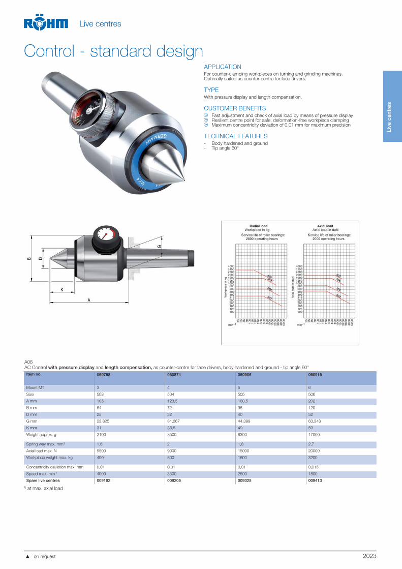
APPLICATIONFor counter-clamping workpieces on turning and grinding machines.Optimally suited as counter-centre for face drivers.
TYPEWith pressure display and length compensation.
CUSTOMER BENEFITS Fast adjustment and check of axial load by means of pressure display Resilient centre point for safe, deformation-free workpiece clamping Maximum concentricity deviation of 0.01 mm for maximum precision
TECHNICAL FEATURES- Body hardened and ground- Tip angle 60°
A06
AC Control with pressure display and length compensation, as counter-centre for face drivers, body hardened and ground - tip angle 60°
Item no. 060798 060874 060906 060915
Mount MT 3 4 5 6
Size 503 504 505 506
A mm 105 123,5 160,5 202
B mm 64 72 95 120
D mm 25 32 40 52
G mm 23,825 31,267 44,399 63,348
K mm 31 38,5 49 59
Weight approx. g 2100 3500 8300 17000
Spring way max. mm1) 1,6 2 1,8 2,7
Axial load max. N 5500 9000 15000 20000
Workpiece weight max. kg 400 800 1600 3200
Concentricity deviation max. mm 0,01 0,01 0,01 0,015
Speed max. min-1 4000 3500 2500 1800
Spare live centres 009192 009205 009325 009413
1) at max. axial load
Control - standard design
on request
2024
Live
cen
tres
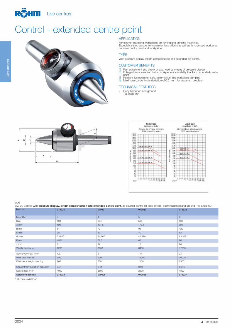
Live centres
APPLICATIONFor counter-clamping workpieces on turning and grinding machines.Especially suited as counter-centre for face drivers as well as for cramped work area between centre point and workpiece.
TYPEWith pressure display, length compensation and extended live centre.
CUSTOMER BENEFITS Fast adjustment and check of axial load by means of pressure display Enlarged work area and better workpiece accessibility thanks to extended centre
point Resilient live centre for safe, deformation-free workpiece clamping Maximum concentricity deviation of 0.01 mm for maximum precision
TECHNICAL FEATURES- Body hardened and ground- Tip angle 60°
A06
AC-VL Control with pressure display, length compensation and extended centre point, as counter-centre for face drivers, body hardened and ground - tip angle 60°
Item no. 079920 079921 079922 079923
Mount MT 3 4 5 6
Size 503 504 505 506
A mm 120 137,5 177,5 223
B mm 64 72 95 120
D mm 25 32 40 52
G mm 23,825 31,267 44,399 63,348
K mm 45,5 52,5 66 80
J mm 11 14 15 24
Weight approx. g 2200 3600 8400 17500
Spring way max. mm1) 1,6 2 1,8 2,7
Axial load max. N 5500 9000 15000 20000
Workpiece weight max. kg 260 550 1100 2500
Concentricity deviation max. mm 0,01 0,01 0,01 0,015
Speed max. min-1 4000 3500 2500 1800
Spare live centres 079924 079925 079926 079927
1) at max. axial load
Control - extended centre point
on request
2025
Live
cen
tres
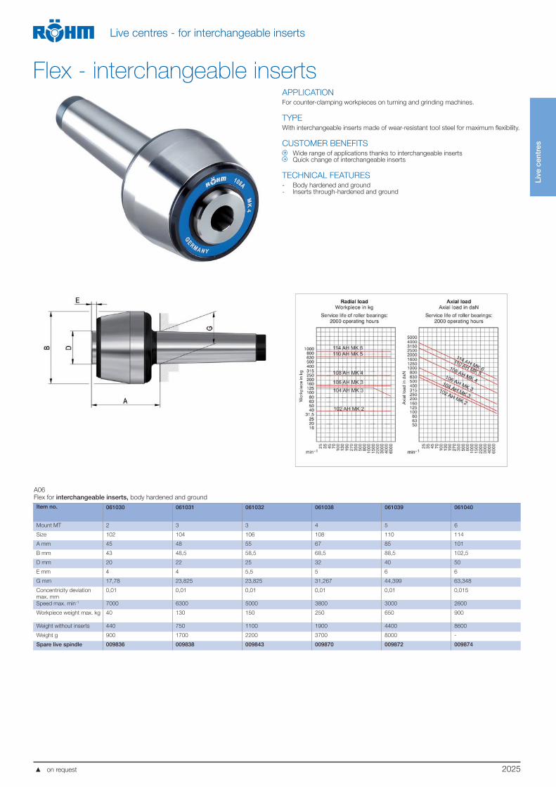
Live centres - for interchangeable inserts
APPLICATIONFor counter-clamping workpieces on turning and grinding machines.
TYPEWith interchangeable inserts made of wear-resistant tool steel for maximum flexibility.
CUSTOMER BENEFITS Wide range of applications thanks to interchangeable inserts Quick change of interchangeable inserts
TECHNICAL FEATURES- Body hardened and ground- Inserts through-hardened and ground
A06
Flex for interchangeable inserts, body hardened and ground
Item no. 061030 061031 061032 061038 061039 061040
Mount MT 2 3 3 4 5 6
Size 102 104 106 108 110 114
A mm 45 48 55 67 85 101
B mm 43 48,5 58,5 68,5 88,5 102,5
D mm 20 22 25 32 40 50
E mm 4 4 5,5 5 6 6
G mm 17,78 23,825 23,825 31,267 44,399 63,348
Concentricity deviation
max. mm
0,01 0,01 0,01 0,01 0,01 0,015
Speed max. min-1 7000 6300 5000 3800 3000 2600
Workpiece weight max. kg 40 130 150 250 650 900
Weight without inserts 440 750 1100 1900 4400 8600
Weight g 900 1700 2200 3700 8000 -
Spare live spindle 009836 009838 009843 009870 009872 009874
Flex - interchangeable inserts
on request
2026
Live
cen
tres
Live centres - for interchangeable inserts
Interchangeable insertsA06
Interchangeable inserts 60°
Item no. Size A mm D mm E mm F mm G mm
070725 102 16 7 5,2 18 20
070728 104 20 12 9,6 24 24
070731 106 24 12 9,6 24 27,5
070734 108 28 15 12 30 31,5
070737 110 38 22 18,5 35 43
070740 114 50 28 24 40 54
A06
Interchangeable inserts 90°
Item no. Size A mm D mm E mm F mm G mm
070727 102 16 7 5,2 18 14,5
070730 104 20 12 9,6 24 16,5
070733 106 24 12 9,6 24 19
070736 108 28 15 12 30 21,5
070739 110 38 22 18,5 35 29
070742 114 50 28 24 40 36
A06
Interchangeable inserts 60°VL
Item no. Size A mm D mm E mm F mm G mm J mm
070719 102 14 7 5,2 18 25 6
070720 104; 106 18 12 9,6 24 30 8
070721 108 26 15 12 30 43 12
070722 110 32 22 18,5 35 55 13
070723 114 42 28 24 40 70 18,5
A06
Interchangeable inserts for tubular workpieces 60°
Item no. Size A mm D mm E mm F mm G mm J mm
070700 102 25 7 5,2 18 21 10
070701 104 35 12 9,6 24 26 15
070702 106 45 12 9,6 24 27 25
070703 108 55 15 12 30 31,5 30
070704 110 70 22 18,5 35 39 40
070705 114 100 28 24 40 52 55
A06
Interchangeable inserts A for centreless workpieces 60°
Item no. Size A mm D mm E mm F mm G mm M mm N mm
070707 102 25 7 5,2 18 18 20 10
070708 104 35 12 9,6 24 24 30 15
070709 106 45 12 9,6 24 25 40 25
070710 108 55 15 12 30 30 48 30
070711 110 70 22 18,5 35 39 63 40
070712 114 100 28 24 40 52 90 55
on request
2027
Live
cen
tres
Live centres - for interchangeable inserts
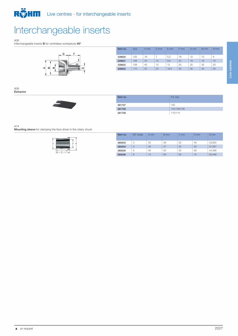
Interchangeable insertsA06
Interchangeable inserts B for centreless workpieces 60°
Item no. Size A mm D mm E mm F mm G mm M mm N mm
228620 102 16 7 5,2 18 12 12 6
228621 106 22 12 9,6 24 16 18 10
228622 108 40 15 12 30 25 35 20
308632 110 52 22 18,5 35 30 45 30
A06
Extractor
Item no. For size
061707 102
061708 104/106/108
061709 110/114
A14
Mounting sleeve for clamping the face driver in the rotary chuck
A
CD
G B
Item no. MT inside A mm B mm C mm D mm G mm
085033 3 32 39 32 40 23,825
085034 4 40 47 42 50 31,267
085035 5 55 62 52 60 44,399
085036 6 75 83 62 70 63,448
on request
2028
Live
cen
tres
Live centres - for interchangeable inserts
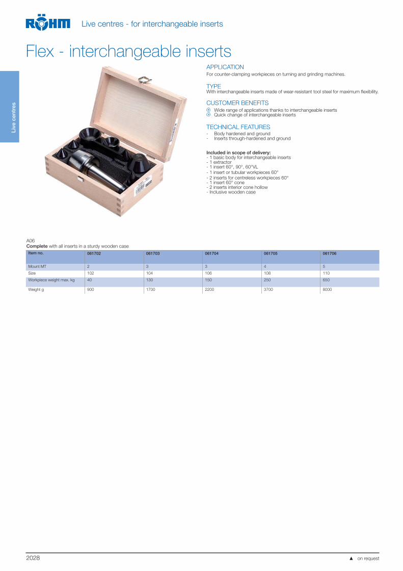
APPLICATIONFor counter-clamping workpieces on turning and grinding machines.
TYPEWith interchangeable inserts made of wear-resistant tool steel for maximum flexibility.
CUSTOMER BENEFITS Wide range of applications thanks to interchangeable inserts Quick change of interchangeable inserts
TECHNICAL FEATURES- Body hardened and ground- Inserts through-hardened and ground
Included in scope of delivery:- 1 basic body for interchangeable inserts- 1 extractor- 1 insert 60°, 90°, 60°VL
- 1 insert or tubular workpieces 60°
- 2 inserts for centreless workpieces 60°- 1 insert 60° cone- 2 inserts interior cone hollow- Inclusive wooden case
A06
Complete with all inserts in a sturdy wooden case
Item no. 061702 061703 061704 061705 061706
Mount MT 2 3 3 4 5
Size 102 104 106 108 110
Workpiece weight max. kg 40 130 150 250 650
Weight g 900 1700 2200 3700 8000
Flex - interchangeable inserts
on request

2029
REVOLVING CENTERING TAPER
Large clamping range for a wide range of boreholes and centres
Robust precision bearing for high axial and radial loads
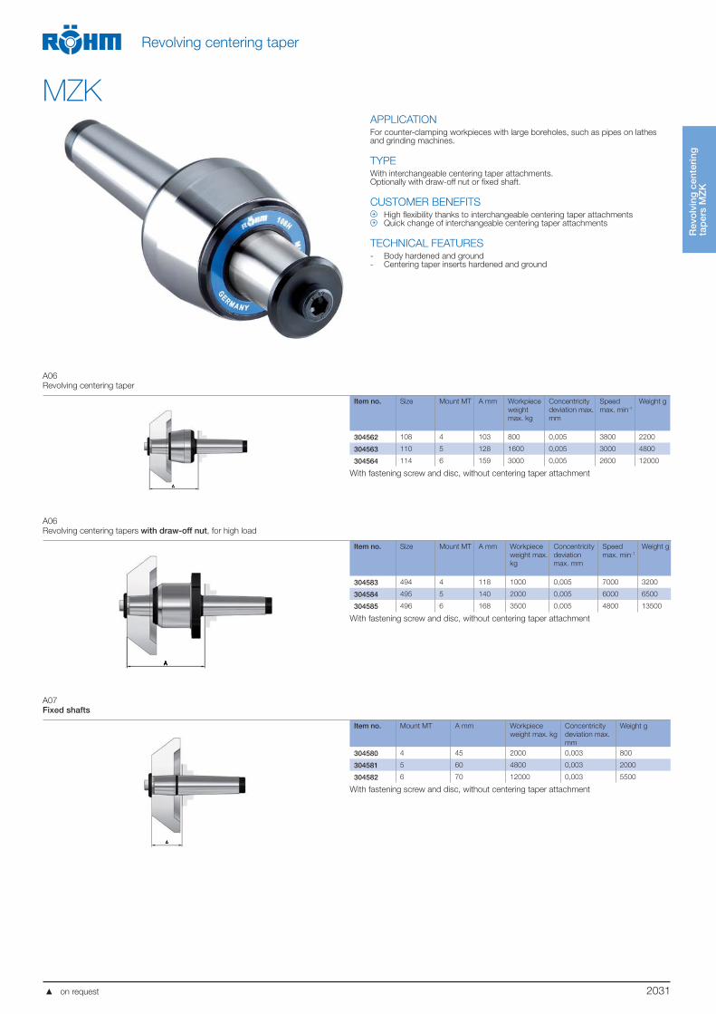
REVOLVING CENTERING TAPER
REVOLVING CENTERING TAPER WITH INTERCHANGEABLE INSERTS
Maximum flexibility thanks to use of exchangeable centering taper attachments
Quick change of centering taper attachment in case of wear
Rev
olv
ing
cen
teri
ng
tap
erFor counter-clamping workpieces with large boreholes, (e.g. pipes) on turning and grinding machi-
nes, in one set-up. The centre point of the revolving centering taper from RÖHM is hardened and
ground for maximum wear resistance.
2030
Rev
olv
ing
cen
teri
ng
tap
ers
MZ
K
Revolving centering taper
MZKAPPLICATION For counter-clamping workpieces with large boreholes, such as pipes on lathes and grinding machines.
TYPERevolving centering taper in pointed version or cone truncated version.
CUSTOMER BENEFITS Large clamping range for a wide range of boreholes and centres Proven 3-fold bearing for high axial and radial load
TECHNICAL FEATURES- Body hardened and ground
A06
Revolving centering taper, pointed, as revolving centre for tubular workpieces as well as centre for machining standard workpieces
Item no. Size Mount
MT
A
mm
B
mm
G Workpiece
weight max.
kg
Concentricity
deviation
max. mm
Speed
max. min-1
Weight g
010613 272 2 61 42 17,78 200 0,01 6000 400
010635 273 3 79 56 23,825 400 0,008 6000 1100
010638 274 4 100 64 31,267 800 0,008 4000 1600
010642 275 5 115,5 78 44,399 1600 0,008 4000 3600
306396 276 6 153 105 63,348 2500 0,008 2500 10000
A06
Revolving centering taper, cone truncated, 60°
Item no. Size Mount
MT
A
mm
B
mm
D
mm
E
mm
G Workpiece
weight
max. kg
Concentricity
deviation
max. mm
Speed
max. min-1
Weight g
301616 171a 2 65 50 20 52 17,78 200 0,008 6000 1200
301556 172 2 77 80 30 64 17,78 300 0,008 5000 2000
301557 172a 3 77 80 30 64 23,825 400 0,008 5000 2200
221605 173 3 96,5 120 30 83 23,825 600 0,008 4000 4200
301558 172b 4 78,5 80 30 64 31,267 400 0,008 5000 2300
044023 173a 4 98 120 30 83 31,267 800 0,008 4000 4500
090483 173b 5 99 120 30 83 44,399 800 0,008 4000 5300
A06
Revolving centering taper, cone truncated, 75°
Item no. Size Mount
MT
A
mm
B
mm
D
mm
E
mm
G Workpiece
weight max.
kg
Concentricity
deviation
max. mm
Speed
max. min-1
Weight
g
301559 172 2 80 80 20 67 17,78 300 0,008 5000 2000
301560 172a 3 80 80 20 67 23,825 400 0,008 5000 2000
062211 173 3 85,5 120 30 72 23,825 600 0,008 4000 4200
301561 172b 4 81,5 80 20 67 31,267 400 0,008 5000 2400
062224 173a 4 87 120 30 72 31,267 800 0,008 4000 4300
062299 174 4 107 170 50 90 31,267 1200 0,01 2800 9700
062232 173b 5 88 120 30 72 44,399 800 0,008 4000 5100
063614 174a 5 106 170 50 90 44,399 1600 0,01 2800 10600
063662 175 5 146,5 250 75 130 44,399 2000 0,01 2200 34000
063633 174b 6 107,5 170 50 90 63,348 1600 0,01 2800 13300
063656 175a 6 148 250 75 130 63,348 2000 0,01 2200 37000
063680 176 6 184 350 120 168 63,348 4000 0,015 1200 82000
on request
2031
Rev
olv
ing
cen
teri
ng
tap
ers
MZ
K
Revolving centering taper
MZKAPPLICATIONFor counter-clamping workpieces with large boreholes, such as pipes on lathes and grinding machines.
TYPEWith interchangeable centering taper attachments.Optionally with draw-off nut or fixed shaft.
CUSTOMER BENEFITS High flexibility thanks to interchangeable centering taper attachments Quick change of interchangeable centering taper attachments
TECHNICAL FEATURES- Body hardened and ground- Centering taper inserts hardened and ground
A06
Revolving centering taper
Item no. Size Mount MT A mm Workpiece
weight
max. kg
Concentricity
deviation max.
mm
Speed
max. min-1
Weight g
304562 108 4 103 800 0,005 3800 2200
304563 110 5 128 1600 0,005 3000 4800
304564 114 6 159 3000 0,005 2600 12000
With fastening screw and disc, without centering taper attachment
A06
Revolving centering tapers with draw-off nut, for high load
Item no. Size Mount MT A mm Workpiece
weight max.
kg
Concentricity
deviation
max. mm
Speed
max. min-1
Weight g
304583 494 4 118 1000 0,005 7000 3200
304584 495 5 140 2000 0,005 6000 6500
304585 496 6 168 3500 0,005 4800 13500
With fastening screw and disc, without centering taper attachment
A07
Fixed shafts
Item no. Mount MT A mm Workpiece
weight max. kg
Concentricity
deviation max.
mm
Weight g
304580 4 45 2000 0,003 800
304581 5 60 4800 0,003 2000
304582 6 70 12000 0,003 5500
With fastening screw and disc, without centering taper attachment
on request
2032
Rev
olv
ing
cen
teri
ng
tap
ers
MZ
K
Revolving centering taper
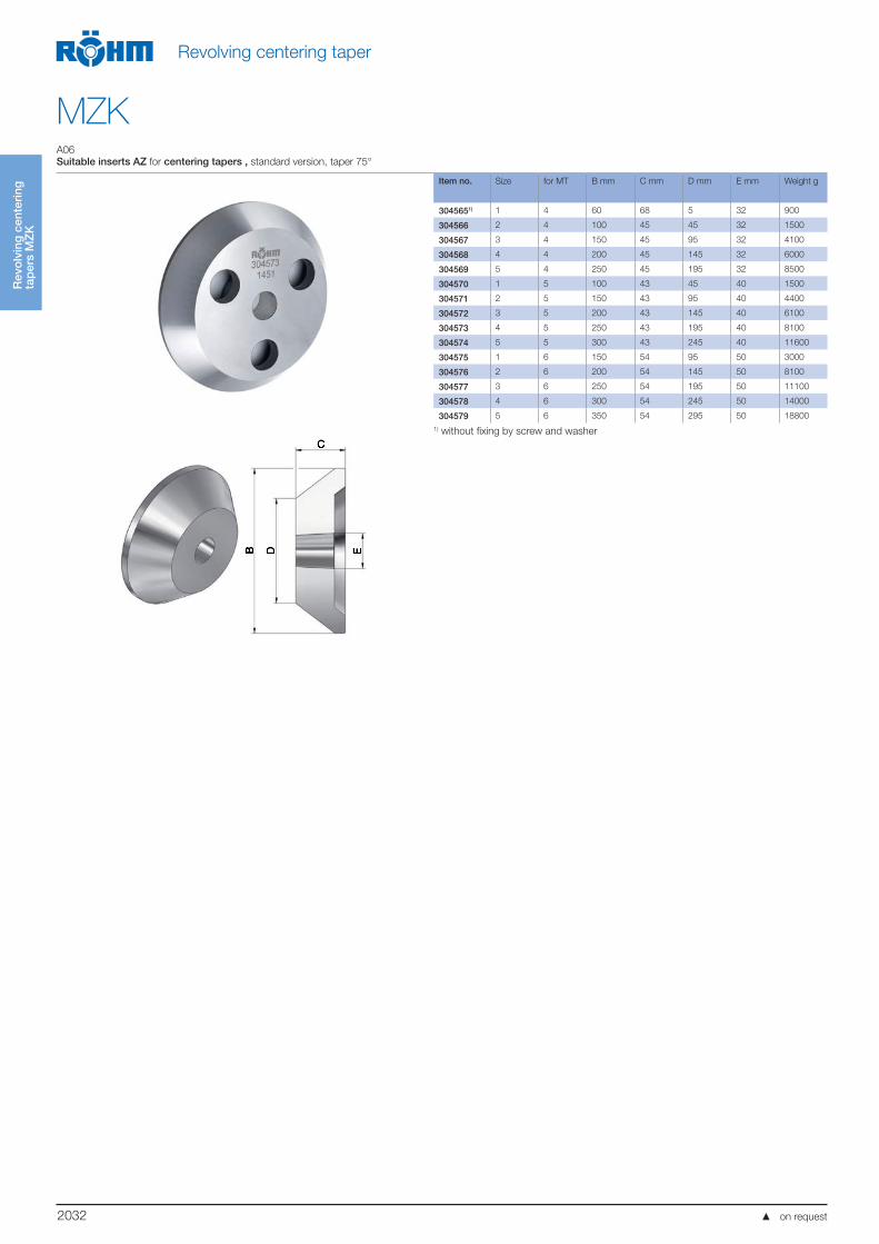
MZKA06
Suitable inserts AZ for centering tapers , standard version, taper 75°
Item no. Size for MT B mm C mm D mm E mm Weight g
3045651) 1 4 60 68 5 32 900
304566 2 4 100 45 45 32 1500
304567 3 4 150 45 95 32 4100
304568 4 4 200 45 145 32 6000
304569 5 4 250 45 195 32 8500
304570 1 5 100 43 45 40 1500
304571 2 5 150 43 95 40 4400
304572 3 5 200 43 145 40 6100
304573 4 5 250 43 195 40 8100
304574 5 5 300 43 245 40 11600
304575 1 6 150 54 95 50 3000
304576 2 6 200 54 145 50 8100
304577 3 6 250 54 195 50 11100
304578 4 6 300 54 245 50 14000
304579 5 6 350 54 295 50 18800
1) without fixing by screw and washer
on request
2033
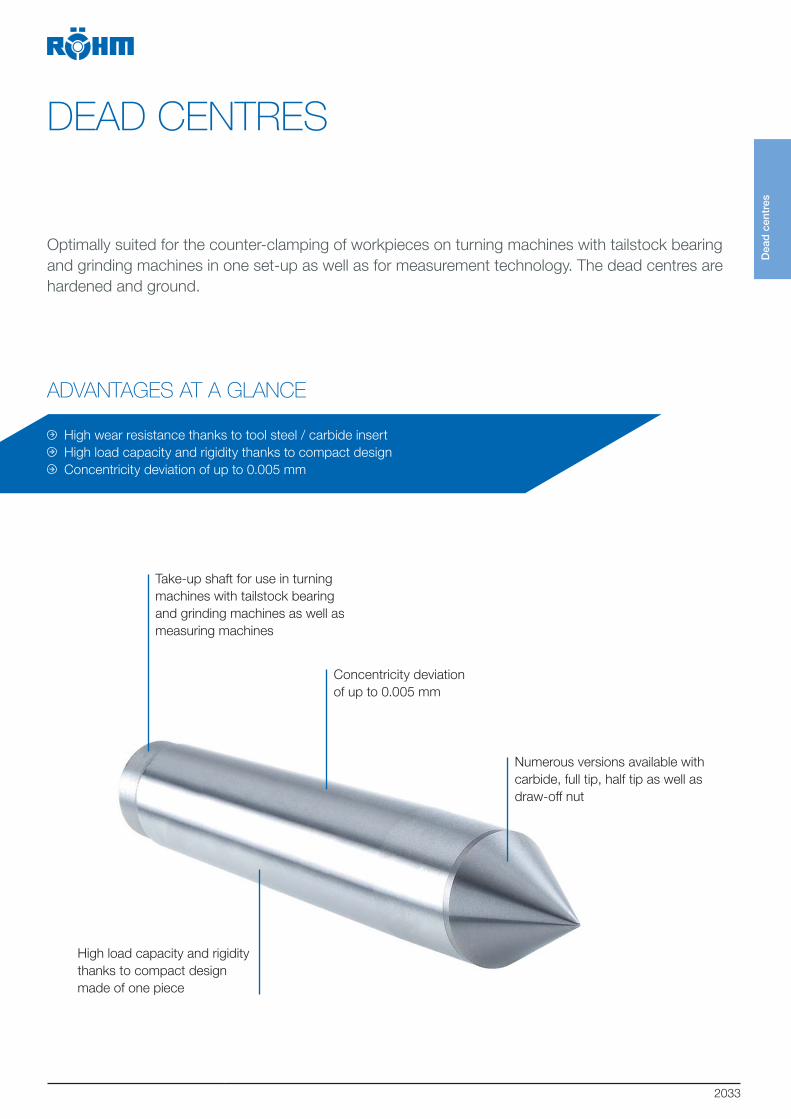
DEAD CENTRES
ADVANTAGES AT A GLANCE
Take-up shaft for use in turning
machines with tailstock bearing
and grinding machines as well as
measuring machines
High wear resistance thanks to tool steel / carbide insert
High load capacity and rigidity thanks to compact design
Concentricity deviation of up to 0.005 mm
High load capacity and rigidity
thanks to compact design
made of one piece
Numerous versions available with
carbide, full tip, half tip as well as
draw-off nut
Concentricity deviation
of up to 0.005 mm
Dea
d c
entr
es
Optimally suited for the counter-clamping of workpieces on turning machines with tailstock bearing
and grinding machines in one set-up as well as for measurement technology. The dead centres are
hardened and ground.

2034
Dea
d c
entr
es
Dead centres
FZSAPPLICATIONFor counter-clamping workpieces on lathes with tailstock bearing and grinding machines.
TYPEDesigns with concentricity of 0.003 mm or higher are available on request.
CUSTOMER BENEFITS High wear resistance thanks to tool steel / carbide insert High load capacity and rigidity since tips are one piece
TECHNICAL FEATURES- Dead centres are hardened and ground
A07
DIN 806, full point, ground, with full carbide tip
Item no. Mount MT A mm B mm d1 mm l1 mm Weight g
326786 2 18 100 17,78 36 175
306402 3 24,1 125 23,825 44 400
221398 4 31,6 160 31,267 57,5 855
326816 5 44,7 200 44,399 70,5 2160
A07
DIN 806, full point, ground, with carbide insert and regrinding line
Item no. Mount MT A mm B mm D mm d1 mm l1 mm Weight g
017171 2 18 100 7 17,78 36 155
017172 3 24,1 125 11 23,825 44 360
017173 4 31,6 160 14 31,267 57,5 770
017174 5 44,7 200 18 44,399 70,5 1950
A07
DIN 806, full point, material: Mat.
Item no. Mount MT A mm B mm d1 mm l1 mm Weight g
013706 0 9,2 70 9,045 20 30
013707 1 12,2 80 12,065 26,5 60
013709 2 18 100 17,78 36 150
013711 3 24,1 125 23,825 44 340
013712 4 31,6 160 31,267 57,5 760
013715 5 44,7 200 44,399 70,5 1920
013718 6 63,8 270 63,348 88 5200
on request

2035
Dea
d c
entr
es
Dead centres
FZSA07
Similar DIN 807, full point, with draw-off nut, material: Mat.
Item no. Mount
MT
A mm B mm C d1 mm l1 mm Key-width
SW
Weight g
005654 3 24,1 138 M27x1,5 23,825 57 19 580
005357 4 31,6 175 M36x1,5 31,267 72,5 27 800
005381 5 44,7 217 M48x1,5 44,399 87,5 36 2900
005426 6 63,8 290 M68x1,5 63,348 108 55 7200
A07
Similar DIN 807, full point, with draw-off nut, with extended point, material: Mat.
Item no. Mount
MT
A mm B mm C D mm d1 mm l1 mm Key-width
SW
Weight
g
249576 3 24,1 148 M27x1,5 10 23,825 67 19 600
249577 4 31,6 186,5 M36x1,5 14 31,267 84 27 1285
249578 5 44,7 242 M48x1,5 16 44,399 112 36 3000
249579 6 63,8 330 M68x1,5 20 63,348 148 55 7900
A07
Draw-off nut
Item no. C H mm Key-width SW Weight
g
005656 M27x1,5 17,5 41 110
005359 M36x1,5 21 55 240
005383 M48x1,5 23 75 480
005428 M68x1,5 25,5 100 900
A07
DIN 806, half point, ground only, with carbide insert
Item no. Mount
MT
A mm B mm D mm E mm F mm d1 mm l1 mm Weight g
027439 2 18 100 7 11 30 17,78 36 150
027440 3 24,1 125 11 15 38 23,825 44 335
026571 4 31,6 160 14 21 50 31,267 57,5 750
027441 5 44,7 200 18 29,4 63 44,399 70,5 1830
A07
DIN 806, half point, material: Mat.
Item no. Mount
MT
A mm B mm E mm F mm d1 mm l1 mm Weight g
013868 2 18 100 11 30 17,78 36 145
013870 3 24,1 125 15 38 23,825 44 310
013871 4 31,6 160 21 50 31,267 57,5 710
013997 5 44,7 200 29,4 63 44,399 70,5 1925
on request
2036
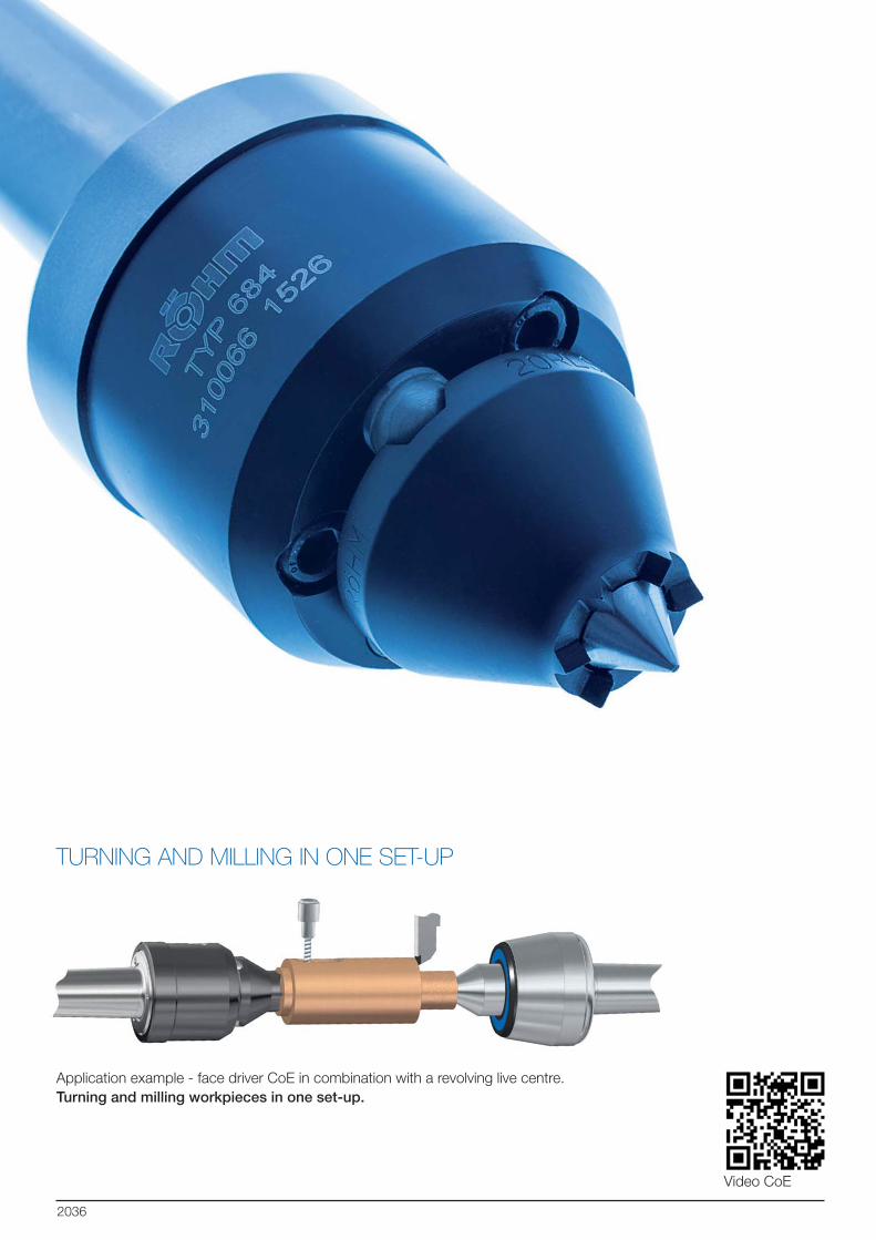
TURNING AND MILLING IN ONE SET-UP
Video CoE
Application example - face driver CoE in combination with a revolving live centre.
Turning and milling workpieces in one set-up.
2037
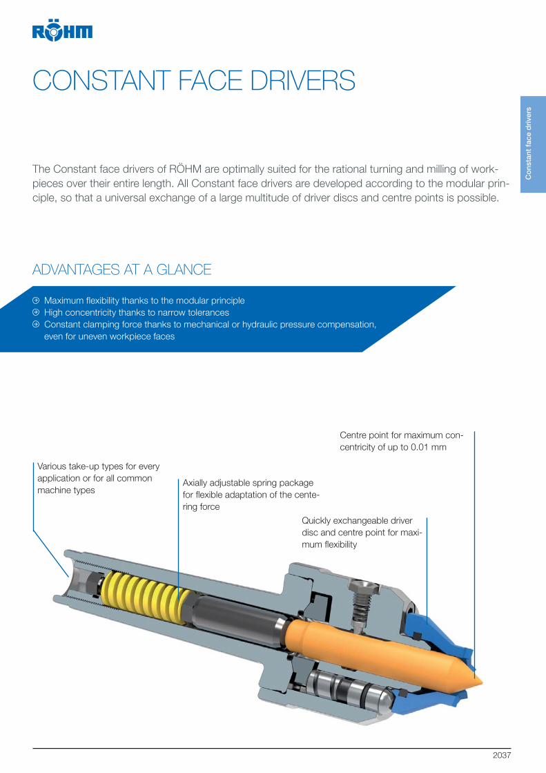
CONSTANT FACE DRIVERS
ADVANTAGES AT A GLANCE
The Constant face drivers of RÖHM are optimally suited for the rational turning and milling of work-
pieces over their entire length. All Constant face drivers are developed according to the modular prin-
ciple, so that a universal exchange of a large multitude of driver discs and centre points is possible.
Centre point for maximum con-
centricity of up to 0.01 mm
Axially adjustable spring package
for flexible adaptation of the cente-
ring force
Various take-up types for every
application or for all common
machine types
Quickly exchangeable driver
disc and centre point for maxi-
mum flexibility
Maximum flexibility thanks to the modular principle
High concentricity thanks to narrow tolerances
Constant clamping force thanks to mechanical or hydraulic pressure compensation,
even for uneven workpiece faces
Co
nsta
nt f
ace
dri
vers
2038
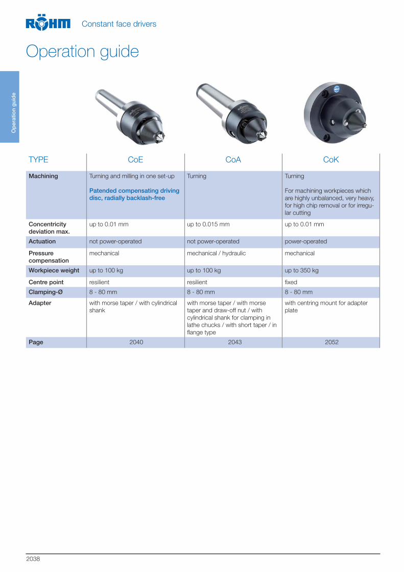
TYPE CoE CoA CoK
Machining Turning and milling in one set-up
Patended compensating driving disc, radially backlash-free
Turning Turning
For machining workpieces which
are highly unbalanced, very heavy,
for high chip removal or for irregu-
lar cutting
Concentricity deviation max.
up to 0.01 mm up to 0.015 mm up to 0.01 mm
Actuation not power-operated not power-operated power-operated
Pressure compensation
mechanical mechanical / hydraulic mechanical
Workpiece weight up to 100 kg up to 100 kg up to 350 kg
Centre point resilient resilient fixed
Clamping-Ø 8 - 80 mm 8 - 80 mm 8 - 80 mm
Adapter with morse taper / with cylindrical
shank
with morse taper / with morse
taper and draw-off nut / with
cylindrical shank for clamping in
lathe chucks / with short taper / in
flange type
with centring mount for adapter
plate
Page 2040 2043 2052
Op
erat
ion
gui
de
Constant face drivers
Operation guide
2039
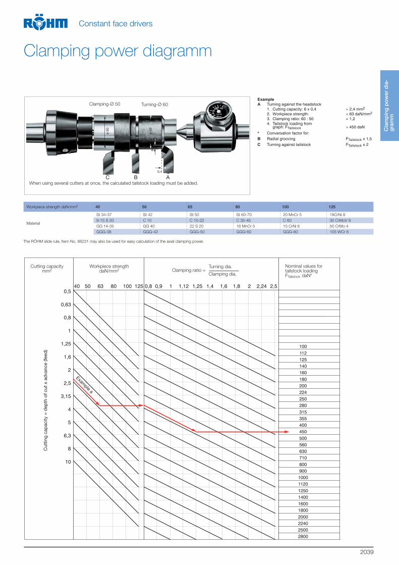
Spanungsquerschnitt WerkstückfestigkeitdaN/mm
2 Dreh-Ø
Spannkreis-ØSpannverhältnis= Richtwerte für
Reitstockkraft
40 50 63 80 100 125 0,8 0,9 1 1,12 1,25 1,4 1,6 1,8 2 2,24 2,50,5
0,63
0,8
1
1,25
1,6
2
2,5
3,15
4
5
6,3
8
10
100
112125140160
180200224250280
315355400450
500560630710
80090010001120
1250140016001800
2000224025002800
Spanquerschnitt=SpantiefexVorschub
Spannkreis-Ø 50
Bei gleichzeitigem Einsatz mehrerer Stähle sind die ermittelten Reitstockkräfte zu addieren.
Dreh-Ø 6005 ø
06 ø6
0,4
C B A
Workpiece strength daN/mm2 40 50 63 80 100 125
Material
St 34-37 St 42 St 50 St 60-70 20 MnCr 5 18CrNi 8
9-15 S 20 C 10 C 15-22 C 35-45 C 60 30 CrMoV 9
GG 14-35 GG 40 22 S 20 16 MnCr 5 15 CrNi 6 50 CrMo 4
GGG-38 GGG-42 GGG-50 GGG-60 GGG-80 105 WCr 6
The RÖHM slide rule, Item No. 88231 may also be used for easy calculation of the axial clamping power.
Cla
mp
ing
po
wer
dia
-g
ram
m
Constant face drivers
Clamping power diagramm
When using several cutters at once, the calculated tailstock loading must be added.
Clamping-Ø 50 Turning-Ø 60
ExampleA
BC
Cutting capacitymm2
Workpiece strengthdaN/mm2
Nominal values for tailstock loading
FTailstock daN*
Turning dia.
Clamping dia.Clamping ratio =
Cut
ting
capa
city
= d
epth
of c
ut x
adv
ance
(fee
d)
Example a
2040
Co
nsta
nt f
ace
dri
vers
C
oE
Constant face drivers
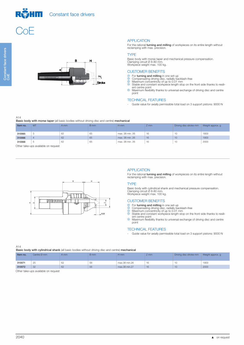
CoEAPPLICATIONFor the rational turning and milling of workpieces on its entire length without reclamping with max. precision.
TYPEBasic body with morse taper and mechanical pressure compensation.Clamping circuit Ø 8-80 mm.Workpiece weight max. 100 kg.
CUSTOMER BENEFITS For turning and milling in one set-up Compensating driving disc, radially backlash-free Maximum concentricity of up to 0.01 mm Stable and constant workpiece length stop on the front side thanks to resili-
ent centre point Maximum flexibility thanks to universal exchange of driving disc and centre
point
TECHNICAL FEATURES- Guide value for axially permissible total load on 3 support pistons: 9000 N
A14
Basic body with morse taper (all basic bodies without driving disc and centre) mechanical
Item no. MT A mm B mm H mm Z mm Driving disc stroke mm Weight approx. g
310065 3 62 65 max. 38 min. 26 16 10 1800
310066 4 62 65 max. 38 min. 26 16 10 1900
310068 5 62 65 max. 38 min. 26 16 10 2000
Other take-ups available on request
APPLICATIONFor the rational turning and milling of workpieces on its entire length without reclamping with max. precision.
TYPE Basic body with cylindrical shank and mechanical pressure compensation.Clamping circuit Ø 8-80 mm.Workpiece weight max. 100 kg.
CUSTOMER BENEFITS For turning and milling in one set-up Compensating driving disc, radially backlash-free Maximum concentricity of up to 0.01 mm Stable and constant workpiece length stop on the front side thanks to resili-
ent centre point Maximum flexibility thanks to universal exchange of driving disc and centre
point
TECHNICAL FEATURES- Guide value for axially permissible total load on 3 support pistons: 9000 N
A14
Basic body with cylindrical shank (all basic bodies without driving disc and centre) mechanical
Item no. Centre Ø mm A mm B mm H mm Z mm Driving disc stroke mm Weight approx. g
310071 25 62 56 max.38 min.26 16 10 1900
310072 32 62 56 max.38 min.27 16 10 2000
Other take-ups available on request
D
B H
A
HUB
Z
on request
2041
Fac
e d
rive
rac
cess
ori
es C
oE
Constant face drivers
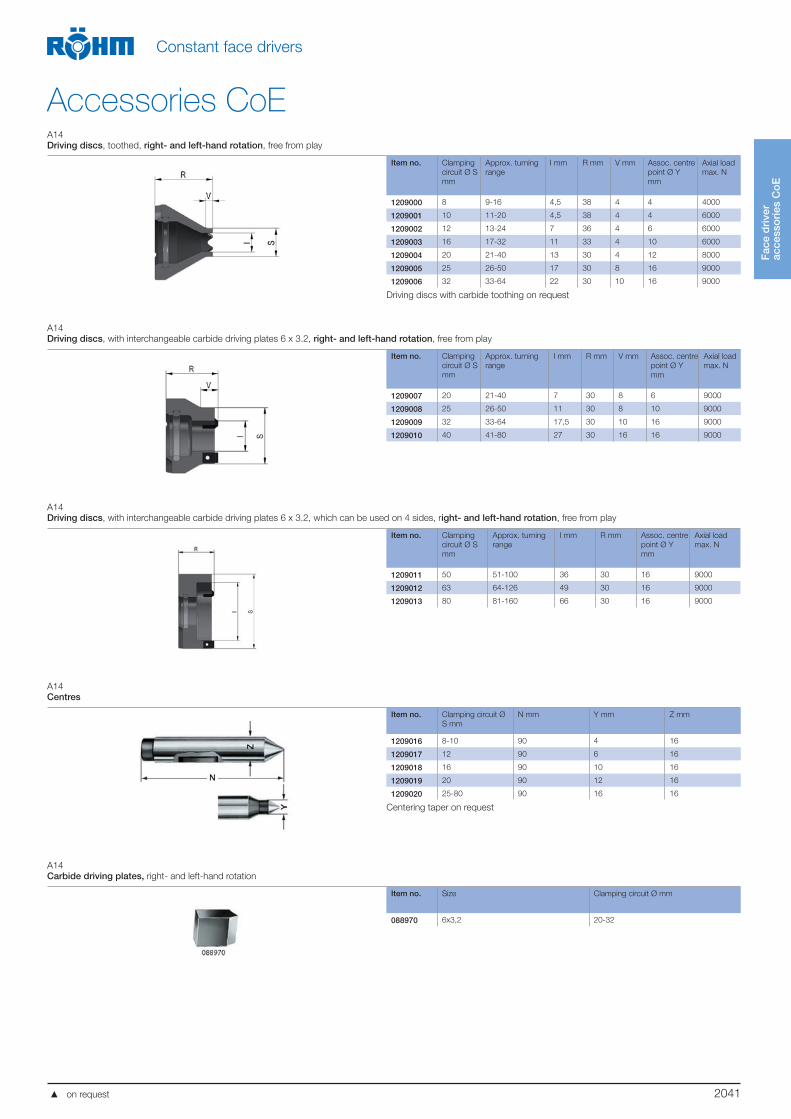
Accessories CoEA14
Driving discs, toothed, right- and left-hand rotation, free from play
Item no. Clamping
circuit Ø S
mm
Approx. turning
range
I mm R mm V mm Assoc. centre
point Ø Y
mm
Axial load
max. N
1209000 8 9-16 4,5 38 4 4 4000
1209001 10 11-20 4,5 38 4 4 6000
1209002 12 13-24 7 36 4 6 6000
1209003 16 17-32 11 33 4 10 6000
1209004 20 21-40 13 30 4 12 8000
1209005 25 26-50 17 30 8 16 9000
1209006 32 33-64 22 30 10 16 9000
Driving discs with carbide toothing on request
A14
Driving discs, with interchangeable carbide driving plates 6 x 3.2, right- and left-hand rotation, free from play
Item no. Clamping
circuit Ø S
mm
Approx. turning
range
I mm R mm V mm Assoc. centre
point Ø Y
mm
Axial load
max. N
1209007 20 21-40 7 30 8 6 9000
1209008 25 26-50 11 30 8 10 9000
1209009 32 33-64 17,5 30 10 16 9000
1209010 40 41-80 27 30 16 16 9000
A14
Driving discs, with interchangeable carbide driving plates 6 x 3.2, which can be used on 4 sides, right- and left-hand rotation, free from play
Item no. Clamping
circuit Ø S
mm
Approx. turning
range
I mm R mm Assoc. centre
point Ø Y
mm
Axial load
max. N
1209011 50 51-100 36 30 16 9000
1209012 63 64-126 49 30 16 9000
1209013 80 81-160 66 30 16 9000
A14
Centres
Item no. Clamping circuit Ø
S mm
N mm Y mm Z mm
1209016 8-10 90 4 16
1209017 12 90 6 16
1209018 16 90 10 16
1209019 20 90 12 16
1209020 25-80 90 16 16
Centering taper on request
A14
Carbide driving plates, right- and left-hand rotation
Item no. Size Clamping circuit Ø mm
088970 6x3,2 20-32
on request

2042
Fac
e d
rive
r ac
cess
ori
es C
oE
Constant face drivers
Accessories CoEA14
Mounting sleeve, for clamping the face driver in the lathe chuck
A
CD
G B
Item no. MT inside A mm B mm C mm D mm G mm
085033 3 32 39 32 40 23,825
085034 4 40 47 42 50 31,267
085035 5 55 62 52 60 44,399
CoE - product rangesA14
CoE-small assortment in wooden box, mechanical pressure compensation, clamping circuit ø 12-50, turning range 13-100 mm
Included in delivery: 1x basic body, 4x driving discs (clamping circuit Ø 12, 20, 32, 50), 3x centre points (centering Ø 6, 12, 16)
Item no. MT Weight approx. g
1209048 3 3600
1209049 4 3870
1209050 5 4550
on request
2043
Co
nsta
nt f
ace
dri
vers
C
oA
Constant face drivers
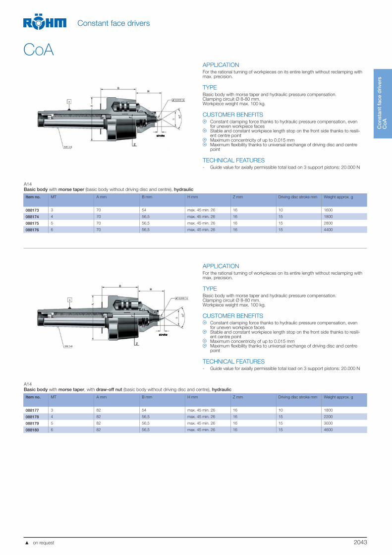
CoAAPPLICATIONFor the rational turning of workpieces on its entire length without reclamping with max. precision.
TYPEBasic body with morse taper and hydraulic pressure compensation.Clamping circuit Ø 8-80 mm.Workpiece weight max. 100 kg.
CUSTOMER BENEFITS Constant clamping force thanks to hydraulic pressure compensation, even
for uneven workpiece faces Stable and constant workpiece length stop on the front side thanks to resili-
ent centre point Maximum concentricity of up to 0.015 mm Maximum flexibility thanks to universal exchange of driving disc and centre
point
TECHNICAL FEATURES- Guide value for axially permissible total load on 3 support pistons: 20.000 N
A14
Basic body with morse taper (basic body without driving disc and centre), hydraulic
Item no. MT A mm B mm H mm Z mm Driving disc stroke mm Weight approx. g
088173 3 70 54 max. 45 min. 26 16 10 1600
088174 4 70 56,5 max. 45 min. 26 16 15 1800
088175 5 70 56,5 max. 45 min. 26 16 15 2800
088176 6 70 56,5 max. 45 min. 26 16 15 4400
APPLICATIONFor the rational turning of workpieces on its entire length without reclamping with max. precision.
TYPEBasic body with morse taper and hydraulic pressure compensation.Clamping circuit Ø 8-80 mm.Workpiece weight max. 100 kg.
CUSTOMER BENEFITS Constant clamping force thanks to hydraulic pressure compensation, even
for uneven workpiece faces Stable and constant workpiece length stop on the front side thanks to resili-
ent centre point Maximum concentricity of up to 0.015 mm Maximum flexibility thanks to universal exchange of driving disc and centre
point
TECHNICAL FEATURES- Guide value for axially permissible total load on 3 support pistons: 20.000 N
A14
Basic body with morse taper, with draw-off nut (basic body without driving disc and centre), hydraulic
Item no. MT A mm B mm H mm Z mm Driving disc stroke mm Weight approx. g
088177 3 82 54 max. 45 min. 26 16 10 1800
088178 4 82 56,5 max. 45 min. 26 16 15 2200
088179 5 82 56,5 max. 45 min. 26 16 15 3000
088180 6 82 56,5 max. 45 min. 26 16 15 4600
on request
2044
Co
nsta
nt f
ace
dri
vers
C
oA
Constant face drivers
CoA
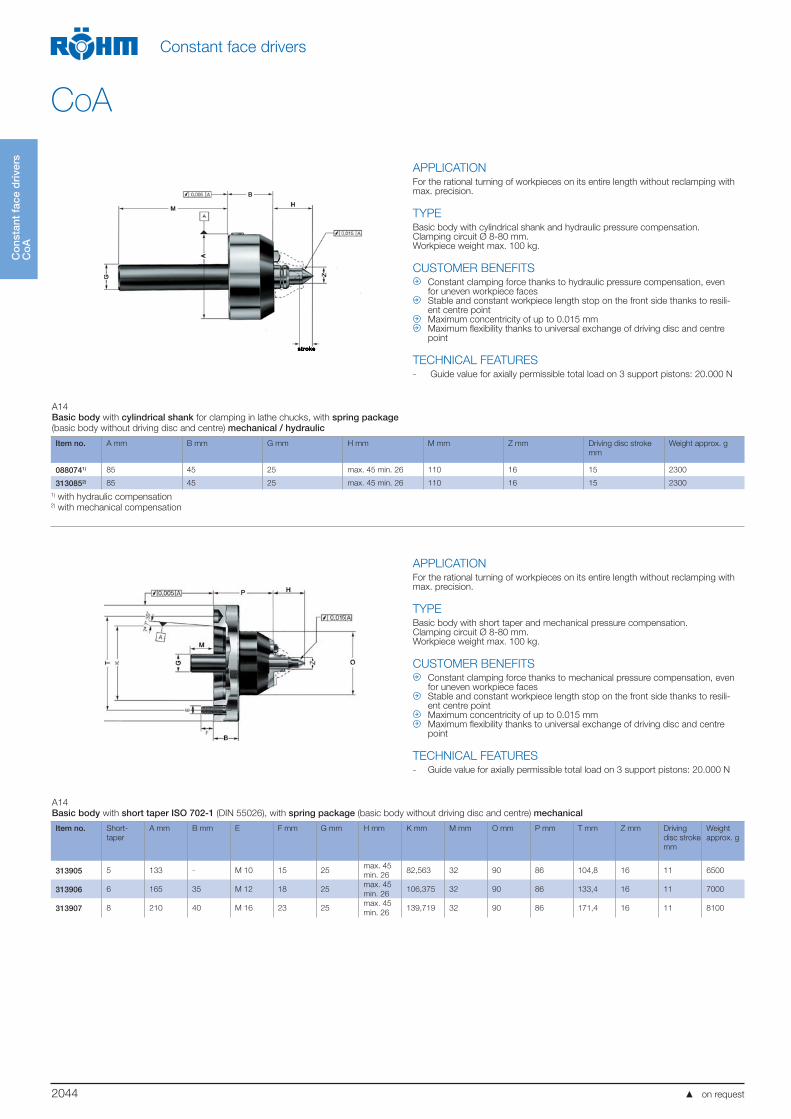
APPLICATIONFor the rational turning of workpieces on its entire length without reclamping with max. precision.
TYPEBasic body with cylindrical shank and hydraulic pressure compensation.Clamping circuit Ø 8-80 mm.Workpiece weight max. 100 kg.
CUSTOMER BENEFITS Constant clamping force thanks to hydraulic pressure compensation, even
for uneven workpiece faces Stable and constant workpiece length stop on the front side thanks to resili-
ent centre point Maximum concentricity of up to 0.015 mm Maximum flexibility thanks to universal exchange of driving disc and centre
point
TECHNICAL FEATURES- Guide value for axially permissible total load on 3 support pistons: 20.000 N
A14
Basic body with cylindrical shank for clamping in lathe chucks, with spring package (basic body without driving disc and centre) mechanical / hydraulic
Item no. A mm B mm G mm H mm M mm Z mm Driving disc stroke
mm
Weight approx. g
0880741) 85 45 25 max. 45 min. 26 110 16 15 2300
3130852) 85 45 25 max. 45 min. 26 110 16 15 2300
1) with hydraulic compensation2) with mechanical compensation
APPLICATIONFor the rational turning of workpieces on its entire length without reclamping with max. precision.
TYPEBasic body with short taper and mechanical pressure compensation.Clamping circuit Ø 8-80 mm.Workpiece weight max. 100 kg.
CUSTOMER BENEFITS Constant clamping force thanks to mechanical pressure compensation, even
for uneven workpiece faces Stable and constant workpiece length stop on the front side thanks to resili-
ent centre point Maximum concentricity of up to 0.015 mm Maximum flexibility thanks to universal exchange of driving disc and centre
point
TECHNICAL FEATURES- Guide value for axially permissible total load on 3 support pistons: 20.000 N
A14
Basic body with short taper ISO 702-1 (DIN 55026), with spring package (basic body without driving disc and centre) mechanical
Item no. Short-
taper
A mm B mm E F mm G mm H mm K mm M mm O mm P mm T mm Z mm Driving
disc stroke
mm
Weight
approx. g
313905 5 133 - M 10 15 25max. 45
min. 2682,563 32 90 86 104,8 16 11 6500
313906 6 165 35 M 12 18 25max. 45
min. 26106,375 32 90 86 133,4 16 11 7000
313907 8 210 40 M 16 23 25max. 45
min. 26139,719 32 90 86 171,4 16 11 8100
5
on request
2045
Co
nsta
nt f
ace
dri
vers
C
oA
Constant face drivers
CoA
APPLICATIONFor the rational turning of workpieces on its entire length without reclamping with max. precision.
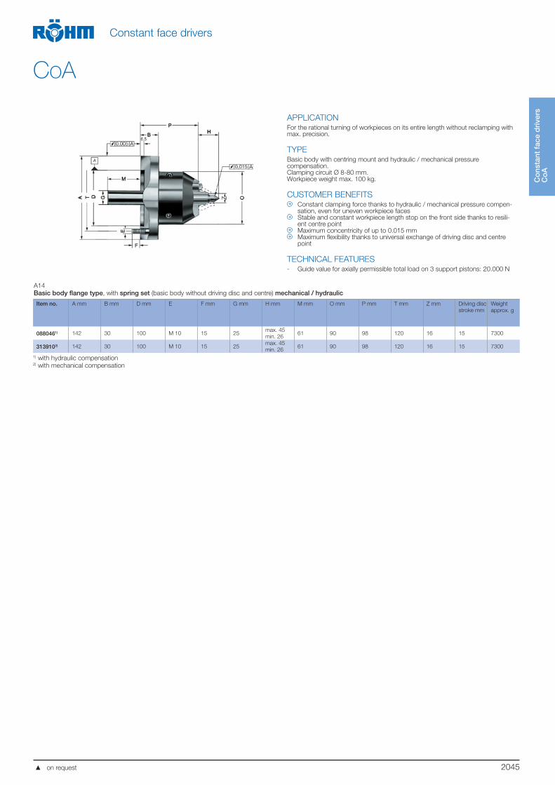
TYPEBasic body with centring mount and hydraulic / mechanical pressure compensation.Clamping circuit Ø 8-80 mm.Workpiece weight max. 100 kg.
CUSTOMER BENEFITS Constant clamping force thanks to hydraulic / mechanical pressure compen-
sation, even for uneven workpiece faces Stable and constant workpiece length stop on the front side thanks to resili-
ent centre point Maximum concentricity of up to 0.015 mm Maximum flexibility thanks to universal exchange of driving disc and centre
point
TECHNICAL FEATURES- Guide value for axially permissible total load on 3 support pistons: 20.000 N
A14
Basic body flange type, with spring set (basic body without driving disc and centre) mechanical / hydraulic
Item no. A mm B mm D mm E F mm G mm H mm M mm O mm P mm T mm Z mm Driving disc
stroke mm
Weight
approx. g
0880461) 142 30 100 M 10 15 25max. 45
min. 2661 90 98 120 16 15 7300
3139102) 142 30 100 M 10 15 25max. 45
min. 2661 90 98 120 16 15 7300
1) with hydraulic compensation2) with mechanical compensation
on request
2046
Co
nsta
nt f
ace
dri
vers
C
oA
Constant face drivers
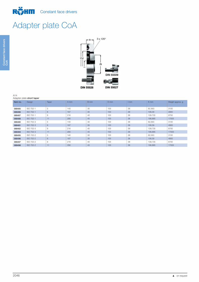
Adapter plate CoA
A14
Adapter plate short taper
Item no. Design Taper A mm B mm D mm I mm K mm Weight approx. g
088485 ISO 702-1 5 140 30 100 38 82,563 3100
088486 ISO 702-1 6 167 35 100 38 106,39 4800
088487 ISO 702-1 8 216 40 100 38 139,735 8700
088488 ISO 702-1 11 280 45 100 38 196,885 17000
088480 ISO 702-3 5 140 30 100 38 82,563 3100
088481 ISO 702-3 6 167 35 100 38 106,39 4800
088482 ISO 702-3 8 216 40 100 38 139,735 8700
088483 ISO 702-3 11 280 45 100 38 196,885 17000
088495 ISO 702-2 5 140 30 100 38 82,563 3100
088496 ISO 702-2 6 167 35 100 38 106,39 4800
088497 ISO 702-2 8 216 40 100 38 139,735 8700
088498 ISO 702-2 11 280 45 100 38 196,885 17000
on request
2047
Acc
esso
ries
fac
e d
rive
rs C
oA
Constant face drivers
Accessories CoAA14
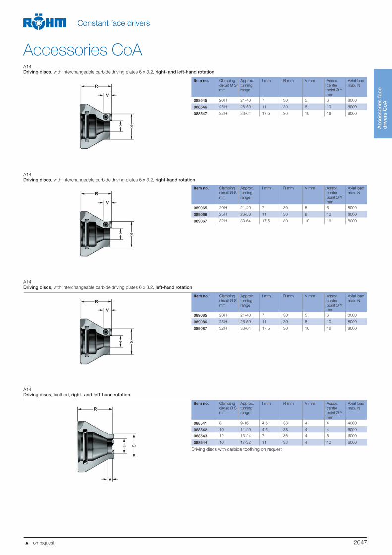
Driving discs, with interchangeable carbide driving plates 6 x 3.2, right- and left-hand rotation
Item no. Clamping
circuit Ø S
mm
Approx.
turning
range
I mm R mm V mm Assoc.
centre
point Ø Y
mm
Axial load
max. N
088545 20 H 21-40 7 30 5 6 8000
088546 25 H 26-50 11 30 8 10 8000
088547 32 H 33-64 17,5 30 10 16 8000
A14
Driving discs, with interchangeable carbide driving plates 6 x 3.2, right-hand rotation
Item no. Clamping
circuit Ø S
mm
Approx.
turning
range
I mm R mm V mm Assoc.
centre
point Ø Y
mm
Axial load
max. N
089065 20 H 21-40 7 30 5 6 8000
089066 25 H 26-50 11 30 8 10 8000
089067 32 H 33-64 17,5 30 10 16 8000
A14
Driving discs, with interchangeable carbide driving plates 6 x 3.2, left-hand rotation
Item no. Clamping
circuit Ø S
mm
Approx.
turning
range
I mm R mm V mm Assoc.
centre
point Ø Y
mm
Axial load
max. N
089085 20 H 21-40 7 30 5 6 8000
089086 25 H 26-50 11 30 8 10 8000
089087 32 H 33-64 17,5 30 10 16 8000
A14
Driving discs, toothed, right- and left-hand rotation
Item no. Clamping
circuit Ø S
mm
Approx.
turning
range
I mm R mm V mm Assoc.
centre
point Ø Y
mm
Axial load
max. N
088541 8 9-16 4,5 38 4 4 4000
088542 10 11-20 4,5 38 4 4 6000
088543 12 13-24 7 36 4 6 6000
088544 16 17-32 11 33 4 10 6000
Driving discs with carbide toothing on request
on request
2048
Acc
esso
ries
fac
e d
rive
rs C
oA
Constant face drivers
Accessories CoAA14
Driving discs, toothed, right-hand rotation
Item no. Clamping
circuit Ø S
mm
Approx.
turning
range
I mm R mm V mm Assoc.
centre
point Ø Y
mm
Axial load
max. N
088061 8 9-16 4,5 38 4 4 4000
088062 10 11-20 4,5 38 4 4 6000
088063 12 13-24 7 36 4 6 6000
088064 16 17-32 11 33 4 10 6000
088065 20 21-40 13 30 4 12 8000
088066 25 26-50 17 30 8 16 10000
088067 32 33-64 22 30 10 16 12500
Driving discs with carbide toothing, friction lining or diamond grain on request
A14
Driving discs, toothed, left-hand rotation
Item no. Clamping
circuit Ø S
mm
Approx.
turning
range
I mm R mm V mm Assoc.
centre
point Ø Y
mm
Axial load
max. N
088081 8 9-16 4,5 38 4 4 4000
088082 10 11-20 4,5 38 4 4 6000
088083 12 13-24 7 36 4 6 6000
088084 16 17-32 11 33 4 10 6000
088085 20 21-40 13 30 4 12 8000
088086 25 26-50 17 30 8 16 10000
088087 32 33-64 22 30 10 16 12500
Driving discs with carbide toothing on request
A14
Driving discs, with interchangeable carbide driving plates 6 x 3.2, right- and left-hand rotation
Item no. Clamping
circuit Ø S
mm
Approx.
turning
range
H mm C mm Assoc.
centre point
Ø Y mm
Axial load
max. N
088548 40 41-80 20 24 16 14000
088549 50 51-100 28 24 16 14000
088550 63 64-126 41 24 16 14000
088551 80 81-160 58 24 16 14000
A14
Driving discs, with interchangeable carbide driving plates 6 x 3.2, right-hand rotation
Item no. Clamping
circuit Ø S
mm
Approx.
turning
range
H mm C mm Assoc.
centre point
Ø Y mm
Axial load
max. N
088068 40 41-80 20 24 16 14000
088069 50 51-100 28 24 16 14000
088070 63 64-126 41 24 16 14000
088071 80 81-160 58 24 16 14000
on request
2049
Acc
esso
ries
fac
e d
rive
rs C
oA
Constant face drivers
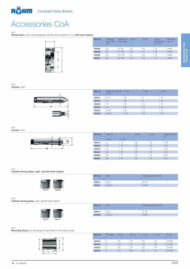
Accessories CoAA14
Driving discs, with interchangeable carbide driving plates 6 x 3.2, left-hand rotation
Item no. Clamping
circuit Ø S
mm
Approx. tur-
ning range
H mm C mm Assoc.
centre point
Ø Y mm
Axial load
max. N
088088 40 41-80 20 24 16 14000
088089 50 51-100 28 24 16 14000
088090 63 64-126 41 24 16 14000
088091 80 81-160 58 24 16 14000
A14
Centres, CoA
Item no. Clamping circuit Ø
S mm
N mm Y mm Z mm
088351 8-10 90 4 16
088352 12 90 6 16
088353 16 90 10 16
088354 20 90 12 16
088355 25-80 90 16 16
086758 25-80 110 16 16
A14
Centres, CoA
Item no. Taper Ø N mm Z mm Weight approx.
g
A mm Y mm
086619 21 10 90 16 136
086620 27 16 90 16 153
688878 34 23 90 16 190
086621 40 29 90 16 210
688880 48 37 90 16 250
086622 56 45 90 16 312
A14
Carbide driving plates, right- and left-hand rotation
Item no. Size Clamping circuit Ø mm
088970 6x3,2 20-32
087931 9,5x3,2 40-80
A14
Carbide driving plates, right- or left-hand rotation
088810088209
Item no. Size Clamping circuit Ø mm
088810 6x3,2 20-32
088209 9,5x3,2 40-80
A14
Mounting sleeve, for clamping the face driver in the rotary chuck
Item no. MT inside A mm B mm C mm D mm G mm
085033 3 32 39 32 40 23,825
085034 4 40 47 42 50 31,267
085035 5 55 62 52 60 44,399
085036 6 75 83 62 70 63,448
A
CD
G B
on request
2050
Acc
esso
ries
fac
e d
rive
rs C
oA
Constant face drivers
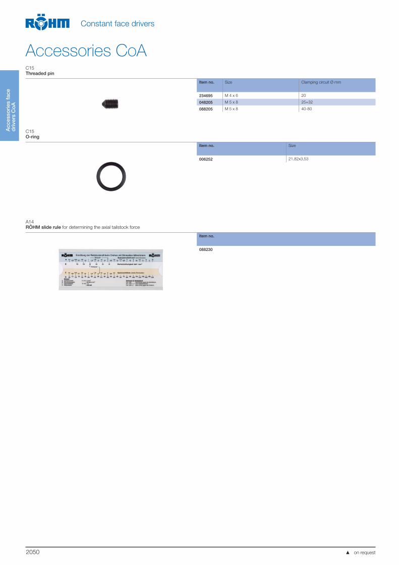
Accessories CoAC15
Threaded pin
Item no. Size Clamping circuit Ø mm
234695 M 4 x 6 20
048205 M 5 x 8 25+32
088205 M 5 x 8 40-80
C15
O-ring
Item no. Size
006252 21,82x3,53
A14
RÖHM slide rule for determining the axial tailstock force
Item no.
088230
on request
2051
Co
nsta
nt f
ace
dri
vers
C
oA
Constant face drivers
CoA - product rangesA14
Basic equipment in a carton, hydraulic pressure compensation, clamping dia. 12 + 32 mm, turning range 13-64 mm
Item no. MT right-hand
rotation
left-hand
rotation
With draw-off
nut
Weight approx.
g
088553 3 2100
088557 3 2400
088573 3 2100
088577 3 2400
088554 4 2400
088558 4 2700
088574 4 2400
088578 4 2700
088555 5 3300
088559 5 3600
088575 5 3300
088579 5 3600
088556 6 4900
088560 6 5200
088576 6 4900
088580 6 5200
A14
Small assortment in wooden box, hydraulic pressure compensation, clamping dia. 12-50 mm, turning range 13-100 mm
Item no. MT right-hand
rotation
left-hand
rotation
With draw-off
nut.
Weight approx.
g
088501 3 3900
088511 3 4200
088521 3 3900
088531 3 4200
088502 4 4300
088512 4 4600
088522 4 4300
088532 4 4600
088503 5 4900
088513 5 5200
088523 5 4900
088533 5 5200
088504 6 6600
088514 6 6800
088524 6 6600
088534 6 6800
A14
Large assortment in wooden box, hydraulic pressure compensation, clamping dia. 10-80 mm, turning range 11-160 mm
Item no. MT right-hand
rotation
left-hand
rotation
With draw-off
nut.
Weight approx.
g
088218 3 5600
088223 3 5600
088233 3 5900
088238 3 5900
088219 4 6000
088224 4 6000
088234 4 6300
088239 4 6300
088220 5 6600
088225 5 6600
088235 5 6900
088240 5 6900
088221 6 8300
088226 6 8300
088236 6 8500
088241 6 8500
Delivery includes:- Basic body
- Driving discs clamping circuit (S) 12 / 20 / 32 / 50
- Centres-Ø (Y) 6 / 12
Delivery includes:- Basic body
- Driving discs clamping circuit (S) 10 /12 / 16 / 20 / 25 /
32 / 40 / 50 /63 / 80
- Centres-Ø (Y) 4 /6 / 10 / 12 / 16
on request

2052
Po
wer
-op
erat
ed f
ace
dri
vers
Co
K
Power-operated face drivers
CoK 8-80 mm
APPLICATIONFor machining workpieces with high unbalance, heavy weight, high chip removal or irregular cutting.
TYPEForce-actuated face driver with mechanical pressure compensation.Clamping circuit Ø 8-80 mm.Workpiece weight max. 350 kg.
CUSTOMER BENEFITS Maximum concentricity of up to 0.01 mm Workpiece longitudinal stop realized in centering Low centering force, even at max. cutting load Maximum flexibility thanks to universal exchange of driving disc and centre
point
TECHNICAL FEATURES- The drivers are pressed against the workpiece with force-actuation
C15
Basic body (without centre, without draw-off nut) mechanical
Item no. A mm B mm D mm E F mm G mm O mm P mm T mm Z mm Driving disc
stroke mm
Weight
approx. g
313900 142 30 100 M 10 15 25 90 93 120 15 5 6500
Draw-off nut M 14x1.5 Id.No. 089229
Adapter plate CoK
A14
Adapter plate short taper
Item no. Design Taper A mm B mm D mm I mm K mm Weight approx. g
088485 ISO 702-1 5 140 30 100 38 82,563 3100
088486 ISO 702-1 6 167 35 100 38 106,39 4800
088487 ISO 702-1 8 216 40 100 38 139,735 8700
088488 ISO 702-1 11 280 45 100 38 196,885 17000
088480 ISO 702-3 5 140 30 100 38 82,563 3100
088481 ISO 702-3 6 167 35 100 38 106,39 4800
088482 ISO 702-3 8 216 40 100 38 139,735 8700
088483 ISO 702-3 11 280 45 100 38 196,885 17000
088495 ISO 702-2 5 140 30 100 38 82,563 3100
088496 ISO 702-2 6 167 35 100 38 106,39 4800
088497 ISO 702-2 8 216 40 100 38 139,735 8700
088498 ISO 702-2 11 280 45 100 38 196,885 17000
on request
2053
Po
wer
-op
erat
ed f
ace
dri
vers
Co
K
Power-operated face drivers
Accessories CoKA14
Driving discs, toothed, right-hand rotation
Item no. Clamping
circuit Ø S
mm
Approx.
turning range
I mm R mm V mm Assoc. centre
point Ø Y mm
Axial load
max. N
088061 8 9-16 4,5 38 4 4 4000
088062 10 11-20 4,5 38 4 4 6000
088063 12 13-24 7 36 4 6 6000
088064 16 17-32 11 33 4 10 6000
088065 20 21-40 13 30 4 12 8000
088066 25 26-50 17 30 8 16 10000
088067 32 33-64 22 30 10 16 12500
Driving discs with carbide toothing, friction lining or diamond grain on request
A14
Driving discs, toothed, left-hand rotation
Item no. Clamping
circuit Ø S
mm
Approx.
turning range
I mm R mm V mm Assoc. centre
point Ø Y mm
Axial load
max. N
088081 8 9-16 4,5 38 4 4 4000
088082 10 11-20 4,5 38 4 4 6000
088083 12 13-24 7 36 4 6 6000
088084 16 17-32 11 33 4 10 6000
088085 20 21-40 13 30 4 12 8000
088086 25 26-50 17 30 8 16 10000
088087 32 33-64 22 30 10 16 12500
Driving discs with carbide toothing on request, friction lining or diamond grain on request
A14
Driving discs, with interchangeable carbide driving plates 6 x 3.2, right-hand rotation
Item no. Clamping circuit
Ø S mm
Approx.
turning range
H mm C mm Assoc. centre
point Ø Y mm
Axial load
max. N
088068 40 41-80 20 24 16 14000
088069 50 51-100 28 24 16 14000
088070 63 64-126 41 24 16 14000
088071 80 81-160 58 24 16 14000
A14
Driving discs, with interchangeable carbide driving plates 6 x 3.2, left-hand rotation
Item no. Clamping circuit
Ø S mm
Approx.
turning range
H mm C mm Assoc. centre
point Ø Y mm
Axial load
max. N
088088 40 41-80 20 24 16 14000
088089 50 51-100 28 24 16 14000
088090 63 64-126 41 24 16 14000
088091 80 81-160 58 24 16 14000
on request
2054
Acc
esso
ries
d
rive
rs C
oK
Power-operated face drivers
Accessories CoKC15
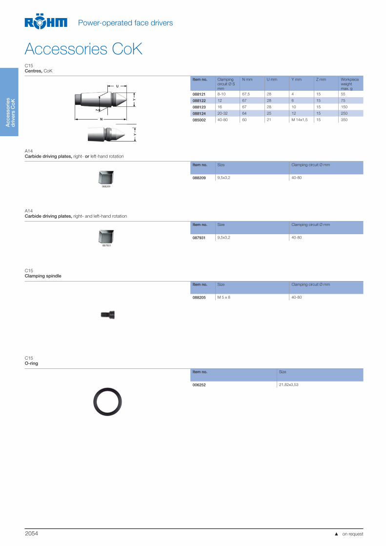
Centres, CoK
Item no. Clamping
circuit Ø S
mm
N mm U mm Y mm Z mm Workpiece
weight
max. g
088121 8-10 67,5 28 4 15 55
088122 12 67 28 6 15 75
088123 16 67 28 10 15 150
088124 20-32 64 25 12 15 250
085002 40-80 60 21 M 14x1,5 15 350
A14
Carbide driving plates, right- or left-hand rotation
Item no. Size Clamping circuit Ø mm
088209 9,5x3,2 40-80
A14
Carbide driving plates, right- and left-hand rotation
Item no. Size Clamping circuit Ø mm
087931 9,5x3,2 40-80
C15
Clamping spindle
Item no. Size Clamping circuit Ø mm
088205 M 5 x 8 40-80
C15
O-ring
Item no. Size
006252 21,82x3,53
088209
on request
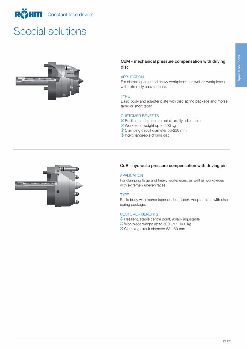
2055
CoM - mechanical pressure compensation with driving disc
APPLICATION
For clamping large and heavy workpieces, as well as workpieces
with extremely uneven faces.
TYPE
Basic body and adapter plate with disc spring package and morse
taper or short taper.
CUSTOMER BENEFITS
Resilient, stable centre point, axially adjustable
Workpiece weight up to 500 kg
Clamping circuit diameter 50-250 mm
Interchangeable driving disc
CoB - hydraulic pressure compensation with driving pin
APPLICATION
For clamping large and heavy workpieces, as well as workpieces
with extremely uneven faces.
TYPE
Basic body with morse taper or short taper. Adapter plate with disc
spring package.
CUSTOMER BENEFITS
Resilient, stable centre point, axially adjustable
Workpiece weight up to 500 kg / 1000 kg
Clamping circuit diameter 63-160 mm
Sp
ecia
l so
lutio
ns
Constant face drivers
Special solutions
RÖHM GmbHHeinrich-Röhm-Straße 5089567 Sontheim/BrenzGermanyTel +49 7325 16 0Fax +49 7325 16 [email protected] www.roehm.biz Id.-Nr. 1178262 / 0915 AU