lithography with self-assembled block copolymer …
TRANSCRIPT

9 Lithography with Self-AssembledBlock Copolymer Microdomains
CHRISTOPHER HARRISONSchulumberger-Doll Research, 36 Old Quarry Road, Ridgefield CT 06877, USA
JOHN A. DAGATANational Institute of Standards and Technology, Gaithersburg MD 20899, USA
DOUGLAS H. ADAMSONPrinceton Materials Institute, Princeton University, Princeton NJ 08540, USA
9.1 INTRODUCTION
9.1.1 MOTIVATION
The quest for faster, cheaper, and more powerful electronics has driven the
semiconductor industry to ever smaller feature sizes, ca. 130 nm at the time of
writing. The ingenuity and success of this industry are breathtaking [1]. As the
expense of lithographic technologies has increased and the importance of
computational power has grown, alternatives to conventional photolithog-
raphy have been put forward by academic and industrial researchers. One
such alternative, the focus of this review, has been the use of block-copolymer
microdomains as a lithographic template. Rather than using photolithography
or electron beam lithography as a means of pattern formation, a block copoly-
mer is allowed to self-assemble into the desired structure. Some degree of
intelligent guidance may be utilized, depending upon the application’s needs.
While self-assembly is generally limited to a few periodic forms of high sym-
metry (e.g. spheres or cylinders), it turns out that there is great use for such
structures in lithography, particularly that related to information storage.
There are many research groups working on block-copolymer lithography;
many more have expressed interest in joining the field. Researchers who are new
to this area will find the broad review of block copolymer thin films by Fasolka
and Mayes [2] to be a highly valuable resource. However, to this researcher’s
knowledge, no comprehensive review of block copolymer lithography currently
exists. Therefore, we undertake one such review here that will enable lithog-
raphy researchers to quickly come up to speed.
Developments in Block Copolymer Science and Technology. Edited by I. W. Hamley# 2004 John Wiley & Sons, Ltd ISBN: 0–470–84335–7

9.1.2 ANECDOTAL ORIGIN OF BLOCK COPOLYMER
LITHOGRAPHY
According to the often-told story, sometime in the late 1980s, P. M. Chaikin
was in the office of L. J. Fetters at Exxon Research and Engineering where he
noticed an electron micrograph of a hexagonal array of dots [3]. The array was
produced by a microphase-separated block copolymer system with a lattice
spacing of 30 nm. Realizing that this length scale was perfect for electron
transport measurements of the so-called Hofstadter butterfly pattern [4], he
began research to harness these patterns as lithographic templates, first putting
P. Mansky on the task [5]. With the help of N. Thomas’s students, they were
able to show that polystyrene-polyisoprene block copolymers were largely
compatible with semiconductor-based lithographic techniques. The addition
of R. A. Register brought further copolymer expertise to the project, especially
concerning the use of ozone for templating nanostructures, the focus of one of
us (C. H.) during his first years in graduate school. Progress was further
facilitated with the synthesis of a wide range of block copolymers by one
(D. H. A.) of us. The project accelerated with the addition of Miri Park
whose nanolithography skills had been honed at the Cornell Nanofabrication
Facility. Indeed, the majority of the initial publications resulted from numerous
trips from Princeton to Ithaca, a perilous journey during the winter. Subsequent
group members continued to develop the technology such that the polymer
pattern could be transferred to semiconductor and metallic films. Since then
many research groups have joined the field and prototypes of products based on
this technology are being evaluated.
9.1.3 EMERGING TECHNOLOGY
A further motivation to writing this chapter has been the use of copolymer
lithography by researchers at the Corporate Research and Development Center
of the Toshiba Corporation. Section 9.7 [6] details their clever use of copolymer
lithography for information storage. These researchers demonstrate that
CoCrPt films can be patterned without difficulty on hard-drive platters that
have been embossed for microdomain templating. While applications such as
this were one of the motivations for academic work over the past decade, until
recently there has been a paucity of projects with a truly applied focus.
9.1.4 OVERVIEW OF CHAPTER
We present an overview of this chapter’s organizational layout. In Section 9.2
we describe polymer synthesis and the resulting self-assembled structures, both
in bulk and thin films. In Section 9.3 we describe the imaging technologies
296 Developments in Block Copolymer Science and Technology

necessary for working in this field. Building on this, we describe the means to
control microdomain orientation in Section 9.4. Section 9.5 discusses the chem-
ical and metallic modifications that are possible to optimize a copolymer
pattern for lithographic use. Section 9.6 describes the progress of researchers
applying conventional lithographic tools to copolymer templates. Finally,
Section 9.7 discusses currently emerging applications and possibilities for the
future.
9.2 SELF-ASSEMBLED STRUCTURES
Self-assembly is a smart means of using chemistry and thermodynamics to
select a desired pattern. While self-assembly can be used in a variety of systems
ranging from surfactant-templated silicates [7] (nanometers) to colloidal disper-
sions (microns) [8], the focus here will be on block copolymers (tens of nano-
meters). Block copolymers with wN � 10 microphase separate above their glass
transition temperature, where w is the Flory–Huggins interaction parameter and
N is the degree of polymerization [9,10]. The resulting morphology depends
largely on the relative volume fraction of the components. Some of the more
commonly seen morphologies are lamellae, cylinders, and spheres (Figure 9.1).
The length scale of microdomains is determined by the length of the polymer
PB
SILICON
SUBSTETRA
PB
PB
SILICON
SUBSTETRA
PB
SILICON
(a)
(b)
(c)
Figure 9.1 Schematic of block-copolymer microdomains in thin films. Panels a and b showone layer of spheres and cylinders, respectively (darker component). Note the additionalwetting layers above and below the microdomains that serve to satisfy the interfacial con-straints; the specific configuration varies depending upon the copolymer system. Panel cshows lamellar sheets oriented parallel to the substrate by the strong alignment influence ofthe substrate and vacuum/polymer interfaces. (Reproduced with permission from the Amer-ican Association for the Advancement of Science)
Lithography with Self-Assembled Block Copolymer Microdomains 297

chains. The thermodynamics of these structures have been extensively examined
in bulk, and more recently, in thin films [2].
9.2.1 CHEMICAL SYNTHESIS
The narrow polydispersity of block copolymers (necessary for self-assembly
with a good degree of long-range order) is greatly facilitated by the use of living
anionic polymerization techniques [11–13]. Anionic polymerization affords a
fairly large selection of monomers and yields materials with well-defined com-
position and well-controlled molecular mass. Due to these advantages, anionic
polymerization is the typical method used in the synthesis of polymers for self-
assembly. Recently, however, some evidence has emerged that certain polydis-
perse systems microphase separate to produce periodic structures with good
order [14].
Nonpolar hydrocarbon monomers such as styrene, isoprene, and butadiene
are polymerized in hydrocarbon solvents such as benzene or cyclohexane.
Initiation is achieved with the use of alkyllithiums such as sec-butyllithium
and molecular mass is controlled by the ratio of initiator to monomer. The
living nature of anionic polymerization allows the syntheses of block copoly-
mers by sequential addition of the monomers. After one monomer is exhausted,
the chain remains reactive, or ‘‘living.’’ The addition of the second monomer
then continues the polymerization to form a block copolymer. Such techniques
are used to synthesize polystyrene-polyisoprene or polystyrene-polybutadiene
copolymers (PS-PI or PS-PB, respectively).
Polar monomers such as 2-vinylpyridine and methyl methacrylate are nor-
mally polymerized in polar solvents such as tetrahydrofuran and at low tem-
perature (�78 8C). In addition, additives such as LiCl are often added to help
lower the rates of termination reactions to levels insignificant in the time frame
of the reaction. Block copolymers made with nonpolar and polar monomers
start with the nonpolar monomer because of its greater reactivity. These active
centers are then typically capped with 1,1-diphenylethylene to lower their
reactivity before the addition of the polar monomer. This helps eliminate side
reactions resulting from addition of the active center to electrophilic sites in the
polar monomers. The two polar polymers, polystyrene-2-vinylpyridine (PS-
P2VP) and polystyrene-poly methyl methacrylate (PS-PMMA) have been
extensively studied in thin films.
Ring-opening anionic polymerization is used in the synthesis of polyferroce-
nyldimethylsilane (PFS) (see section 9.6.3). This mechanism involves nucleo-
philic addition of a polymer anion to a cyclic monomer. The monomer then ring
opens, leading to incorporation of the monomer into the growing chain and
generation of a new anion. This method is not as common as those previously
mentioned, but can result in well-defined polymers with unique chemical
composition.
298 Developments in Block Copolymer Science and Technology

Experimentally, there are two general methods for anionic polymerization.
One is high-vacuum polymerization, and the other is inert-atmosphere poly-
merization. High-vacuum polymerization has the advantage of higher levels of
purity over longer periods of time. This can be very important for high molecu-
lar mass polymers or polymers containing coupling agents that have long
reaction times (months) and must be kept very clean for a long time. The
disadvantage is the added effort and time needed to run a reaction under high
vacuum. The reactor must be made with glass-blowing techniques and the
reactants added by break seals.
Inert-atmosphere techniques, on the other hand, are complementary to high-
vacuum techniques. Rather than using a vacuum, an inert gas such as nitrogen
or argon is used to maintain the absence of moisture, oxygen or carbon dioxide.
Less effort is required, and for simple diblock copolymers, the loss of some
purity may not be detrimental to the self-assembly of the polymers.
A relatively new technique used for the random PI-PS brushes mentioned
later in this review (Section 9.2.2) is controlled-radical polymerization [15–17].
This technique reduces the rate of radical recombination by lowering the
effective concentration of radicals. This new method opens the possibility of
random polymers such as those used in brushes. These polymers have a rela-
tively narrow polydispersity (especially for radically produced polymers).
Hydrogenation is often used to improve the chemical and thermal stability of
polymers. Hydrogenation of isoprene, for instance, saturates the double bonds
to form poly(ethylene propylene) or PEP [18]. This polymer is chemically
distinct from PI and has different properties. One advantage is that PEP is
much less sensitive to oxidation than PI, and so can be heated in the presence of
oxygen with no significant degradation. Hydrogenation is done under hydrogen
pressure, with either soluble or insoluble catalysts. It is possible to hydrogenate
a diene in the presence of styrene, or to hydrogenate the styrene as well.
9.2.2 SELF-ASSEMBLY IN THIN FILMS
While bulk systems are easier to analyze, effective and rapid implementation of
copolymer lithography is contingent upon the fabrication and control of micro-
domains in resist-like thin films. Use of such films can take advantage of well-
developed resist technologies (spin coating and film characterization) thereby
speeding their adaption into fabrication environments. However, the structure
formed by copolymers in bulk or melt state may differ from that of thin films.
Such films can easily be fabricated by spin coating from dilute (ca. 1% wt)
solutions onto smooth silicon wafers where the thickness can be easily tuned by
the usual parameters of spin speed and solution concentration. For films of
thickness comparable to the microdomain spacing (10 nm to 100 nm thick), the
influence of the interface dominates, leading to structures different from that in
bulk. A large fraction of polymer in thin films is devoted to satisfying the
Lithography with Self-Assembled Block Copolymer Microdomains 299

wetting constraints, e.g. PMMA preferably wets silicon wafers in a PS-PMMA
system [2]. Microdomains are often submerged inside the film, though this
depth depends upon the molecular mass and chemistry of the copolymer
system [18]. Films thinner than a critical thickness often exhibit no microdo-
mains as all polymeric material is used to wet the interfaces. Microdomain
structure varies as well – many researchers have noted that copolymers that
form cylinders in bulk form spheres in sufficiently thin films [19]. Lastly, thin
films often suffer from kinetic or pinning influences from the surface that lead
to short microdomain correlation lengths or grain sizes. Surface modifications
have been employed to try to ameliorate surface pinning [20].
9.3 IMAGING MICRODOMAINS IN THIN FILMS
Perhaps the first challenge faced by researchers working on copolymer lithog-
raphy was finding a fast, reliable, and robust imaging technique. Rigorous
diagnosis of the success or failure of each lithography step requires analysis
via an imaging method; since there can be dozens of steps in multilayer lithog-
raphy a rapid technique is essential. There are two dominant imaging tech-
niques that have emerged as strong research tools: the scanning electron
microscope (SEM) and the atomic force microscope (AFM). The instrument
choice depends mainly upon which technique generates higher contrast for each
particular copolymer system, and of course, availability and researcher prefer-
ence.
9.3.1 ELECTRON MICROSCOPY
The earliest work on imaging block copolymer microdomains relied heavily
upon transmission electron microscopy (TEM), and it still proves to be a useful
tool to this day [19]. Samples are either microtomed or solvent cast to produce
thin (ca. 100 nm) sections. PS-PI or PS-PB samples can be stained with osmium
tetroxide to increase contrast. Osmium tetroxide reacts selectively with unsat-
urated double bonds such as found in PI or PB microdomains so as to provide
mass contrast [21]. Unfortunately, TEM requires that the samples be free-
standing or transferred to a transparent support (e.g. carbon), a cumbersome
and time-consuming process that is largely incompatible with silicon or GaAs
wafers. While silicon nitride membranes can be employed for TEM, these
expensive and delicate structures are not easily accessible to all researchers [22].
Compared to TEM, scanning electron microscopy (SEM) suffers from lower
resolution but its ease of use and ability to image surface features have made it
the workhorse of microlithography. Indeed, easy access to SEMs in clean-room
environments plays a large role in its choice by many researchers. Furthermore,
developments in the past decade have made low-voltage, high-resolution
300 Developments in Block Copolymer Science and Technology

SEMmore commonplace in clean rooms, narrowing the resolution gap between
SEM and TEM [23]. Low-voltage SEM (around 1 kV) is advantageous for the
insulating nature of copolymer masks increases its susceptibility to charging
effects. In some cases, a thin metal coating is used to decrease sample charging,
but researchers often find this unnecessary when using the latest generation of
low-voltage scanning electron microscopes–an advantage not be overlooked, as
coating a sample with a nonuniform metal film can obscure important features.
Examples of SEM micrographs of spherical and cylindrical microdomains are
shown in Figure 9.2
Microdomains that present surface topography, such as those formed by PS-
PMMA copolymers, are readily imaged by SEM with standard topography
enhancing operating procedures. However, microdomains of other copolymer
systems such as PS-PI are often submerged beneath a surface wetting layer,
requiring additional steps to enhance contrast. First, conventional OsO4
staining is used to produce contrast in a manner consistent with TEM sample
preparation. In some cases, the operating voltage can be used to image slightly
submerged microdomains. Specifically, low-voltage (1 kV) SEM enhances fea-
tures within the top 10 nm, but by increasing the operating voltage to 5 kV,
features as deep as 25 nm have been successfully imaged [24]. Secondly, for
those features further submerged beneath the surface, reactive ion etching has
been shown to provide an even higher level of contrast; optimal choice of the
etching gas to minimize (or maximize) the selectivity is paramount [18]. Plasma
etching has the added advantage of providing depth information, important in
multilayer systems [25].
9.3.2 ATOMIC FORCE MICROSCOPY
Atomic force microscopy has become a powerful tool for examining the surface
of block copolymer films. Researchers have produced a set of publications on
imaging copolymer microdomains and proved its utility in many, though not
all, copolymer systems [26–29]. Unfortunately, AFMs are often not readily
available in the typical clean-room setting, though their presence is growing.
Additionally, an inexperienced researcher can easily damage the AFM tip, the
recognition of which is a learned skill and leads to a very shallow learning
curve.
An AFM generates contrast by sensing either topographic features or vari-
ation in mechanical properties, the latter by measuring the phase of an oscillat-
ing tip. Tapping mode appears to be the preferred imaging method as indicated
by the frequency of publications that describe its use in imaging polymer films.
For PS-PMMA copolymer systems, Morkved and coworkers [22] have argued
that contrast originates from purely topographic effects, which is plausible as
the moduli of PS and PMMA are virtually identical over a wide range of
temperatures. Alternatively, a modulus difference between microdomains and
Lithography with Self-Assembled Block Copolymer Microdomains 301

(a)
(b)
15 cm
20 cm
Figure 9.2 Panels (a), (b) show representative SEM images of cylinders and spheres,respectively. These images can be interpreted as plan views of the corresponding panels ofFigure 9.1. Bar ¼ 100 nm.
302 Developments in Block Copolymer Science and Technology

the matrix (hard and soft) is sufficient to give rise to contrast in PS-PEP systems
[18]. These researchers have argued that there is virtually no topography in their
samples and that the tip taps through a wetting layer of the softer material to
sense the harder microdomains. However, contrast may originate from an
entirely different mechanism: polymer–tip interactions that strongly depend
upon the polymer chemistry. Lastly, it should be pointed out that it is always
difficult to completely decouple any one of these effects from the others without
extremely careful experiments [28,30].
9.4 MECHANISMS TO CONTROL ORIENTATION
Control over the alignment of microdomains in block copolymer films greatly
increases their utility for lithography. For example, if spherical microdomains
were arranged onto a lattice and modified to form metal nanodots, in theory
each one could function as an addressable memory bit at a density of 1011 per
square centimeter. Similar arguments for cylindrical microdomains suitably
modified to form wires suggest that circuitry could be fabricated if only orien-
tational control could be imposed. With these goals in mind, much effort has
been made to control the orientation of films cast from copolymer solutions.
The surface imposed by a flat interface (i.e. silicon wafer) does strongly affect
the microdomains orientation, but the resulting orientation is not typically
desirable. For example, symmetric copolymers that form lamellae usually orient
with their planes parallel to the wafer interfaces, thereby reducing their utility as
lithographic templates (Figure 9.1c). In an analogous fashion, cylindrical
microdomains in thin films typically orient parallel to the wafer plane, but
their in-plane orientation varies throughout the film. In what follows, we
discuss techniques that have been exploited to control microdomain orientation
with an eye towards optimizing a lithographic template.
9.4.1 ORIENTATION CONTROL THROUGH MICROFABRICATION
OF TEMPLATES
Perhaps the simplest manner in which to control the orientation of microdo-
mains is to impose physical or chemical topography. Until the last year or so,
most efforts in this field had been largely restricted to influencing the features of
polymer islands on topographically or chemically patterned substrates. Heier
and coworkers [31,32] demonstrated that periodic chemical patterning influ-
enced the local thickness of polymer films subsequently applied. They also
demonstrated that a moderate degree of lamellar orientation can be achieved
with chemically patterned substrates. Nealey and coworkers [33–35] have used
an approach where advanced lithography techniques are used to alter the
chemistry of the surface layer in a periodic fashion, thereby influencing the
Lithography with Self-Assembled Block Copolymer Microdomains 303
microdomain orientation of subsequently applied layers. Additionally, it has
been shown that patterned substrate topography can be used to manipulate the
morphology of block copolymer films, such as islands that adopt an anti-
conformal arrangement with respect to surface topography [36–38]. While this
has led to interesting scientific questions, control of cylindrical or spherical
microdomain orientation is the most challenging and most rewarding goal.
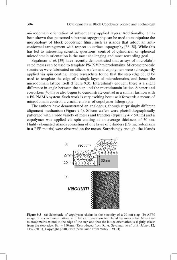
Segalman et al. [39] have recently demonstrated that arrays of microfabri-
cated mesas can be used to template PS-P2VP microdomains. Micrometer-scale
structures were fabricated on silicon wafers and copolymers were subsequently
applied via spin coating. These researchers found that the step edge could be
used to template the edge of a single layer of microdomains, and hence the
microdomain lattice itself (Figure 9.3). Interestingly enough, there is a slight
difference in angle between the step and the microdomain lattice. Sibener and
coworkers [40] have also begun to demonstrate control in a similar fashion with
a PS-PMMA system. Such work is very exciting because it forwards a means of
microdomain control, a crucial enabler of copolymer lithography.
The authors have demonstrated an analogous, though surprisingly different
alignment mechanism (Figure 9.4). Silicon wafers were photolithographically
patterned with a wide variety of mesas and trenches (typically 4� 50 mm) and a
copolymer was applied via spin coating at an average thickness of 30 nm.
Highly elongated islands consisting of one layer of cylinders (PS microdomains
in a PEP matrix) were observed on the mesas. Surprisingly enough, the islands
(a)
(b)
1 cm
Figure 9.3 (a) Schematic of copolymer chains in the vincinity of a 30 nm step. (b) AFMimage of microdomain lattice with lattice orientation templated by mesa edge. Note thatmicrodomains extend to the edge of the step and that the lattice orientation is slightly askewfrom the step edge. Bar ¼ 150 nm. (Reproduced from R. A. Seyalman et al. Adr. Mater. 12,1152 (2001), Copyright (2001) with permission from Witey – VCH).
304 Developments in Block Copolymer Science and Technology

extended along the length of the mesas but the film retracted from the mesa
edge. These elongated islands were observed to effectively orient the cylinders
over dozens of micrometers, though presumably the alignment length is poten-
tially as long as the wafer.
Cheng et al. [41] have recently demonstrated that the spherical microdomains
of a polystyrene-polyferrocenyldimethylsilane (PS-PFS) block copolymer can
be templated by microfabricated grooves. In this case the topographic relief
structures were microfabricated by interference lithography, though presum-
ably conventional lithographic techniques would work as well if high resolution
was obtained. These authors demonstrated that microdomains subsequently
applied aligned with grooves and that the ordering proceeded from the walls
inward. Furthermore, they were able to use these microdomains to fabricate
(a)
0
0.50
0.75
1.00
g 2(r)
µm
(c)
1 2 3(b)
Figure 9.4 (a) Copolymer island (top structure) on silicon mesa (middle structure) fabricatedon silicon wafer (bottom). Mesas are typically fifty micrometers long by four micrometerswide, copolymer film is close to three micrometers wide. (b) After spin coating the copolymerfilm retracts from the mesa edge during annealing and the microdomains orient along thelonger dimension of the island. Bar ¼ 200 nm. (c) Plot of microdomain alignment with mesaedge as a function of distance from mesa edge. g2(r) is the cross-correlation function of themicrodomain alignment with the mesa edge where a value of 1.0 indicates perfect alignment.Note that the plot range almost spans the three-micrometer width of the copolymer island ofpanel (a). The middle of the mesa corresponds to 1.5 micrometers on the graph. At early times(thin line) g2(r) varies between 0.5 to 0.75, reflecting the poor alignment of the microdomains.At later times (thick line) the microdomains become more aligned and g2(r) is closer to 1.0except for a misalignment region in the middle of the mesa. This region (dip on the graph at1.5 micrometers) disappears with further annealing.
Lithography with Self-Assembled Block Copolymer Microdomains 305

silica posts by reactive ion etching. Presumably this technique could be
extended to fabricate an array of W-Co dots as well.
Hot-stage AFM is being used to investigate the kinetics of microdomain
alignment with respect to a microfabricated step edge [26,42]. There has been
some evidence that the alignment near a step edge proceeds faster than the
coarsening process in the absence of a step. The results here are especially
pertinent to the use of microfabricated steps to align microdomains. Defects
may be repelled or absorbed by the step; one may be able to analyze this motion
in an analogous fashion to the motion of image charges. Cheng and coworkers
[41] have confirmed these observations by pointing out that PS-PFS microdo-
mains in grooves align first at the outside and the alignment proceeds towards
the middle.
Finally, it has been shown that the trenches formed by embossing – a much
cheaper process than microlithography – can be used to control the lattice
orientation of spherical microdomains for the purposes of information storage
(see Section 9.7) [43,44]. A thorough understanding of the alignment process
would provide insight into the use of any one of the techniques mentioned in
this section.
9.4.2 ELECTRIC FIELDS
It has been shown that electric fields can be used to align polymeric micro-
domains, typically by taking advantage of the mismatch of the dielectric con-
stants of two or more blocks. Amundson and coworkers [45–47] demonstrated
the effectiveness of such techniques in a bulk PS-PMMA system where the
respective dielectric constants are listed as 2.55 and 3.78, evidently sufficient for
macroscopic alignment. Birefringence analysis was performed to show that the
order parameter, a measure of the degree of field alignment, grew with time
upon application of fields in the range of 15 kV per cm until saturation.
Additionally, defect analysis was performed to correlate the birefringence
data with electron microscopy images.
There have been two main techniques for electric-field alignment in thin
films: in-plane and out-of-plane electrodes. The potential of microfabricated in-
plane electrodes has been elegantly demonstrated by Morkved et al. [48] who
showed that sufficiently strong electric field fields could be generated to align
cylindrical microdomains (Figure 9.5). Though these researchers worked with a
kinetically hindered PS-PMMA system, impressive alignment was demon-
strated by annealing above the glass transition temperature in the presence of
an electric field. TEM analysis of such samples was facilitated by sample
fabrication on silicon nitride membranes. Unfortunately, the region of micro-
domain alignment extended only a micrometer or so beyond the metal elec-
trodes. These researchers estimate that 30 kV/cm is necessary to orient the
microdomains. While the technique demonstration was beautiful, its ultimate
306 Developments in Block Copolymer Science and Technology

use as a mean of generating macroscopic microdomain control would be
challenging as the entire wafer would need to be patterned with electrodes, a
technical challenge.
Thurn-Albrecht et al. [49] have shown that out-of-plane electrodes can force
cylindrical PS microdomains to orient perpendicular to the substrate in a
(a)
(b)
1.4 cm
Figure 9.5 (a) AFM image of cylindrical microdomains in the vicinity of an electrode; fieldhas not yet been applied and the average orientation is random. (b) After application of theelectric field the microdomains have oriented parallel to the field lines emerging normal to theelectrode edge. Bar ¼ 150 nm. (Reproduced from T. L. Morkved et al. Science 273, 931(1996), copyright (1996) with permission from the American Association for the Advance-ment of Science).
Lithography with Self-Assembled Block Copolymer Microdomains 307

PS-PMMA system (Figure 9.6). The alignment field (30V=mm), produced by
metal electrodes above and below the polymer film, acts like a parallel-plate
capacitor with a micrometer-scale separation. While this technique is very
successful in aligning cylinders perpendicular to the substrate, the field has little
or no effect on the packing of the cylinders. A plan view of these structures
reveals a polycrystalline lattice-like structure where each grain adopts a random
orientation. Furthermore, these researchers have used lithography techniques
to erode away PMMA cylinders and back fill with various metals, such as Co
AlKapton
PS
PMMA
Au
Kapton
Air
Nanowires
(a)
(b)
(c)
v
Figure 9.6 Fabrication steps to make an array of nanowires oriented perpendicular to thesubstrate. (a) The PS-PMMA copolymer forms cylinders oriented perpendicular to the sub-strate when poled with an electric field above the glass temperature. (b) The oriented PMMAcylinders are removed by exposure to deep ultraviolet light. (c) Co or Cu wires are grown incylindrical holes by electrodeposition. (Reproduced from T. Thurn-Albrecht et al. Science,290, 2126 (2000), copyright (2000) with permission from the American Association for theAdvancement of Science).
308 Developments in Block Copolymer Science and Technology

and Cu. Coercivity measurements were performed and found to be rather large,
Hc ¼ 800 Oe at 300 K. Here, the wire diameter is much smaller than the
theoretical critical single-domain behavior (around 50 nm) so that single-
domain behavior is possible. These authors suggest that coercivity can be
tailored by the aspect ratio of the wires and their packing density. This method
shows great promise and is an impressive combination of science and technol-
ogy.
9.4.3 SHEAR ALIGNMENT
Shear alignment of bulk polymeric samples has been a standard technique for
decades and its applicability to block copolymers for the purposes of control-
ling order has been soundly demonstrated by both Kornfield and Winey
[50–54]. Such shearing techniques have been extended to thick polymer films
by Albalak and Thomas [55] using counter-rotating cylinders (roll casting). The
simplicity of shear alignment is appealing but challenging to utilize on films
with thicknesses comparable to that of a microdomain. However, some pro-
gress has been made. Typically, a film is cast on a silicon wafer and a second
wafer – treated with adhesion-preventing polymers – is pressed on top and held
under pressure, usually at an elevated temperature. Chou and coworkers [56]
are beginning to investigate the utility of such techniques to align single layers
of microdomains for the purposes of microfabrication. This technique necessi-
tates clean-room conditions as any dust particles between the two wafers will
prevent adequate contact. One alternative route is to replace the treated wafer
with a robust strip of conformal silicone (poly(dimethyl siloxane)). Pressure
could be applied to the polymer-coated wafer through the PDMS at moderately
high temperatures. A few randomly distributed dust particles would not prevent
a large degree of contact between the surfaces. Such techniques may make this
technique accessible to a wider range of researchers.
9.4.4 ALIGNING MICRODOMAINS VERTICALLY THROUGH
INTERFACE CONTROL
Perhaps the earliest contribution to the control of microdomain orientation via
interface control was the experiments of Mansky et al. [5], who demonstrated
that cylindrical microdomains could be oriented perpendicular to a film by
solvent casting on an aqueous surface. It was also demonstrated here that ozone
could be used to selectively remove PB microdomains from a PS matrix, thereby
enabling subsequent research in lithography. However, the uniformity of
this sample preparation method was highly lacking – only certain randomly
distributed regions of samples prepared in this manner yielded perpendicularly
orinted cylinders.
Lithography with Self-Assembled Block Copolymer Microdomains 309

Building on this work, Huang et al. [57,58] have demonstrated that clever
tuning of the interfacial energies of thin films can be used to control micro-
domain orientation in PS-PMMA copolymers. Lamellae were induced to orient
perpendicular to a substrate through the use of random copolymers, as demon-
strated by both small-angle neutron scattering and electron microscopy. PS-
PMMA films were typically cast on surfaces tailored to be neutral to wetting by
either block, leading to the perpendicular orientation. Challenges remain, how-
ever, in assuring the uniformity of alignment throughout the sample, and
increasing the correlation lengths of the microdomains. Perhaps a combination
of this technique with alignment-inducing physical topography would be a
winning combination.
9.4.5 DIRECTIONAL CRYSTALLIZATION
Temperature gradients are extensively used to grow single-crystal silicon ingots,
and their application to polymer microdomains is a natural and intriguing
extension. One typically starts with a seed crystal with a well-determined lattice
orientation and immerses it into a melt to trigger crystallization. Zone refining
(repeated movement of a melting and crystallizing zone) can be exploited to
exclude impurities and defects from the region of interest. Bodycomb and
Hashimoto [59,60] have applied this methodology to bulk lamellar systems to
form well-oriented samples without shear. Further application of this technique
to thin films – facilitated by temperature gradient stages – may provide an
additional pathway to macroscopic sample orientation [61].
Alternatively, one can directionally solidify a crystallizable material for the
purposes of templating the orientation of microdomains. Researchers have
shown that benzoic acid can be suitably crystallized and polystyrene-polyethyl-
ene diblock copolymers that are dissolved into benzoic acid will form micro-
domains with an orientation perpendicular to the substrates [62]. While this is
very powerful, it not clear that suitable solvents can be found for a wide variety
of copolymer systems such that this can be generalized. Additionally, the grain
size of the cylinders is very small, so that addressability of the cylinders is
rendered difficult.
9.4.6 CONTROL VIA FLUIDICS
Thomas and coworkers [62] have used a novel application of microfluidic
technology to begin to control microdomain array orientation. Standard soft
lithography techniques were used to fabricate microfluidic channels out of poly
(dimethyl siloxane) (PDMS) that were placed onto a semiconductor wafer [63].
Polymer solutions were allowed to flow into the channels and the solvent
310 Developments in Block Copolymer Science and Technology

evaporated, resulting in microdomains in controlled areas of the wafer [64]. At
present, little control of the microdomain patterns has been demonstrated, but
this technique has great potential to place polymer films in specific areas of a
wafer, a useful addition for high-throughput measurements.
9.4.7 EMBOSSING
Perhaps the simplest, yet most effective method for templating microdomain
orientation is with physical embossing, such as in the manufacturing of com-
pact discs. For this process a hard master with relief structures is manufactured.
The platter to be embossed is coated with a relatively deformable material, such
as a resist. The resist to be embossed is coated with a ‘‘nonstick’’ surface, such as
chemical species with fluorine groups. Copolymer films can be spin coated onto
such grooved surfaces to template the location of copolymer microdomains
[56]. Koji and coworkers have successfully used this templating methodology
for information technology (Section 9.7).
9.5 METALLIC INCOPORATION OR MODIFICATIONS TO THE
COPOLYMER TEMPLATE
For the purposes of patterning media such as silicon wafers, differentiation of
the microdomains is often desirable. For many systems, both copolymer blocks
are carbonaceous, leading to an etch resistance between the microdomains and
the matrix that is less than desirable (see Section 9.6). However, this can be
differentiated by for example, incorporating metal clusters into one block. In
what follows we describe suitable modification schemes.
9.5.1 METAL INCORPORATION VIA EVAPORATION
The simplest means to template the placement of metal is to evaporate it onto
the proper choice of a copolymer film. For those copolymer blocks with
sufficiently disparate metal–polymer interactions, interfacial energies can be
used to tailor the ultimate location of metallic particles after coalescence.
Segregation of metals into microdomains have been demonstrated in this
manner by Jaeger and coworkers [65,66]. While only a limited set of metals
satisfy the constraints, metal films so fabricated would act as robust masks
(Figure 9.7). Most interestingly, chains of such segregated particles lead to
fascinating transport properties.
Lithography with Self-Assembled Block Copolymer Microdomains 311

9.5.2 METAL INCORPORATION VIA DIRECT SYNTHESIS
Cohen and coworkers [67–69] have made strong contributions to the field of
block copolymers by directly synthesizing metal nanoclusters in copolymer
materials. Starting with organometallic monomers, a variety of processing
means, such as heating or reduction with hydrogen have been employed to
convert the metal atoms to clusters. These researchers have demonstrated the
fabrication of silver, platinum, copper, nickel, and gold nanoclusters. The metal
clusters follow the block copolymer microdomain templates to varying degrees,
with perhaps the greatest success with silver. These techniques have the possi-
(a)
(b)
Figure 9.7 (a) Schematic of PS-PMMA in thin film, where both PS and PMMA componentare exposed to free surface. (b) Evaporated gold on copolymer template, followed by anneal-ing leads to segregation with cylinder loading fractions up to 30 %. Bar ¼ 250 nm. (Repro-duced from W. A. Lopes and H. M. Jaeger, Nature, 414, 735 (2001), copyright (2001) withpermission from Nature Publishing Group).
312 Developments in Block Copolymer Science and Technology
bility of fabricating microdomains with ultimate etch resistance as many metals
are not attacked by reactive ion etching. One disadvantage, however, is that the
metal clusters rarely occupy more than half the microdomain volume, minimiz-
ing the effectiveness of a microdomain mask. Generating continuous metal lines
in the form of cylinders remains a challenge.
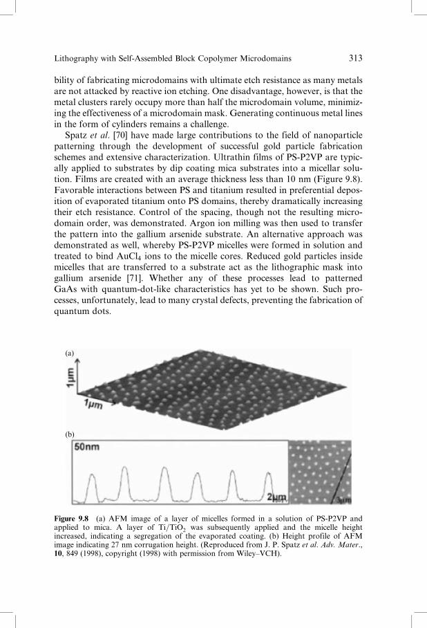
Spatz et al. [70] have made large contributions to the field of nanoparticle
patterning through the development of successful gold particle fabrication
schemes and extensive characterization. Ultrathin films of PS-P2VP are typic-
ally applied to substrates by dip coating mica substrates into a micellar solu-
tion. Films are created with an average thickness less than 10 nm (Figure 9.8).
Favorable interactions between PS and titanium resulted in preferential depos-
ition of evaporated titanium onto PS domains, thereby dramatically increasing
their etch resistance. Control of the spacing, though not the resulting micro-
domain order, was demonstrated. Argon ion milling was then used to transfer
the pattern into the gallium arsenide substrate. An alternative approach was
demonstrated as well, whereby PS-P2VP micelles were formed in solution and
treated to bind AuCl4 ions to the micelle cores. Reduced gold particles inside
micelles that are transferred to a substrate act as the lithographic mask into
gallium arsenide [71]. Whether any of these processes lead to patterned
GaAs with quantum-dot-like characteristics has yet to be shown. Such pro-
cesses, unfortunately, lead to many crystal defects, preventing the fabrication of
quantum dots.
(a)
(b)
Figure 9.8 (a) AFM image of a layer of micelles formed in a solution of PS-P2VP andapplied to mica. A layer of Ti=TiO2 was subsequently applied and the micelle heightincreased, indicating a segregation of the evaporated coating. (b) Height profile of AFMimage indicating 27 nm corrugation height. (Reproduced from J. P. Spatz et al. Adv. Mater.,10, 849 (1998), copyright (1998) with permission from Wiley–VCH).
Lithography with Self-Assembled Block Copolymer Microdomains 313

9.6 LITHOGRAPHIC USE OF TEMPLATES
In this section we focus on the patterning of materials by copolymer templates.
Building on the film preparations of Section 9.5 we discuss chemical-based wet-
etching processes and plasma-based dry-patterning techniques. Ensuring the
compatibility of copolymer etching steps with commonly used processes is
advantageous as it should speed industrial adoption of this technology. We
highlight two successful copolymer templating processes – ozonated PS-PI films
and polyisoprene-polyferrocenyldimethylsilane.
9.6.1 PATTERN TRANSFER METHODOLOGIES: WET AND DRY
Perhaps the simplest and oldest pattern transfer technique is wet etching, which
is surprisingly effective even for copolymer templates. Typical use of wet
etching involves photolithography or electron beam lithography to selectively
expose substrate areas for dissolution. An aggressive liquid etchant is then used
to remove exposed areas of a wafer. One historical drawback has been the
isotropic nature of many etchants so that high aspect features are difficult to
fabricate. However, as will be discussed in Section 9.6, some success has been
reported for copolymer templates.
Dry-etching processes such as reactive ion etching (RIE) and plasma etching
are the dominant tools for pattern transfer of submicrometer features. A pattern
is generated on a resist-coated wafer and this pattern is transferred by a directed
plasma of high-energy ions. Plasmas typically consist of gases of CF4,O2, SF6,
Cl2, or argon. Etching takes place by a combination of physical bombardment
(sputtering) and chemical reactivity to make volatile compounds. Copolymer
lithography was initially demonstrated with a low-power, low-pressure CF4
plasma using a PS-PI system. Low-pressure etching conditions were used to
maximize the average path length of the ions so as to facilitate anisotropic etching
[72,73].
9.6.2 PATTERNING VIA AN OZONATED COPOLYMER TEMPLATE
The earliest patterning techniques took advantage of ozonation to dissolve
microdomains away from the matrix, leaving a single array of pores in a thin
film. This porous film then acted as a standard etching mask, where the pores
presented less etch resistance than the matrix. CF4-based RIE was shown to
be the most effective tool in pattern transfer from the thin film to the substrate.
It was first demonstrated that standard semiconductor materials – such as
silicon or silicon nitride – could be easily and uniformly patterned by this
technique [5,72,73]. Starting with a copolymer-coated silicon wafer, an
hexagonal array of holes with a 20 nm depth and a 40 nm lattice constant
was uniformly etched into the sample (Figure 9.9). These researchers were
314 Developments in Block Copolymer Science and Technology

(a)
(b) (c)
PS PB
Silicon nitride
Ozonated sample Stained sample
Silicon nitride
Silicon nitride Silicon nitride
Silicon nitride
Silicon nitride
Silicon nitride
Silicon nitride
Silicon nitride
Silicon nitride
Silicon nitride
Holes Dots
RIE (CF4 or CF4/O2) RIE (CF4/O2)
RIERIE
Figure 9.9 Two complementary fabrication strategies used by Chaikin and coworkers topattern substrates. The left side shows the removal of microdomains by ozonation, therebyacting as a positive resist. The right side shows the crosslinking of microdomains by staining,thereby acting as a negative resist. In both cases reactive ion etching is used to transfer thetemplate to the substrate. The two processes are used to fabricate holes or dots, respectively.(Reproduced from M. Park et al. Science, 278, 1401 (1997), copyright (1997) with permissionfrom the American Association for the Advancement of Science).
Lithography with Self-Assembled Block Copolymer Microdomains 315

challenged to fabricate deeper holes as the polymer film matrix presented
little etch resistance. This technique was further extended to fabricate an
array of gold dots via a boot-strapping trilevel procedure. Wafers were coated
with a thin layer of polyimide and then coated with an even thinner film of
silicon nitride via plasma-enhanced chemical vapor deposition. A single layer of
copolymer microdomains was applied via spin coating. After appropriate
annealing and ozonation, the copolymer film was used to pattern through the
silicon nitride via CF4 RIE. Using the silicon nitride film as a mask, O2 RIE was
used to pattern cylindrical holes down to the silicon wafer, onto which gold was
evaporated. The polyimide was dissolved away, leaving an array of gold dots on
the wafer [74]. The ultimate goal of these researchers is two-fold; primarily they
are interested in the electron-transport properties of patterned metal films, but
additionally the possibilities for information storage (one bit per dot) are
lucrative [75]. Further extension of this technique includes the fabrication of
metal wires using a template of cylindrical microdomains.
Li et al. [76] were able to employ ozonation technologies to pattern GaAs
substrates using a copolymer template and a combination of wet- and dry-
etching technologies. The ultimate goal of this project is to generate quantum
dots with a tighter size distribution than currently possible via Stranski–
Krastanow growth or metal-organic chemical vapor deposition [77,78]. Starting
with a copolymer-coated GaAs wafer, the microdomains were dissolved away
and the filmswere plasma etched, generating topographical contrast.Wet etching
(mixture of ammonium hydroxide and hydrogen peroxide) was used to transfer
the pattern into GaAs with both the (100) and (311)B orientation. As wet etching
is oftenmore gentle thandirect reactive ion etching, this techniquemay play a role
where disruption of the crystal lattice is not acceptable.
9.6.3 PATTERNING VIA PI-PFS COPOLYMER TEMPLATE
Thomas and coworkers [41,79–82] have demonstrated that a polyisoprene-
polyferrocenyldimethylsilane (PI-PFS) copolymer is a more robust mask as
compared to purely organic copolymers. The ferrous component – which
formed the microdomains – was demonstrated to be strongly resistant to an
oxygen-based plasma. Metal is incorporated directly during polymerization
rather than subsequent modifications to the template. Etch-resistance ratios
as high as 50 were reported for the organic vs ferrous material for an oxygen
plasma. In one demonstration, a boot-strapping process was used where PI-
PFS was used to pattern silicon oxide via oxygen-based RIE, the patterned
silion oxide was used to mask tungsten for etching via CHF3, and finally the
patterned tungsten film was used to pattern a cobalt film. Optimal choice of the
etching gas and conditions used at each step led to optimal patterning (Figure
9.10). These researchers showed that the coercivity increased as a function of
etch depth; arrays of individual dots had a higher coercivity than a continuous
316 Developments in Block Copolymer Science and Technology

(a)
(b)
Figure 9.10 Fabrication strategy used by Thomas and coworkers. (a) Pillars of silicon oxidetopped with oxidized PFS after etching with CHF3 based RIE. (b) Tungsten-topped cobaltdots produced as final product. Bar ¼ 200 nm. (Reproduced from J. Y. Cheng et al. Adv.Mater. 13, 1174 (2001) copyright (2001) with permission from Wiley-VCH).
Lithography with Self-Assembled Block Copolymer Microdomains 317

film. The authors argued that domain-wall motion, necessary to switch mag-
netization direction, was impeded by defects introduced by etching.
9.6.4 PATTERNING VIA PS-PMMA COPOLYMER TEMPLATE
PS-PMMA systems can be used as lithographic templates in a similar manner to
PS-PI systems but with a different degradation mechanism. PMMA degrades
quickly when exposed to ultraviolet light and can then be washed away.
Therefore, after fabrication of a thin film of PS-PMMA microdomains, the
PMMA can be degraded and removed, producing a matrix of voids. These can
then be used as a lithographic template for the purposes of masking a wafer or
filling with metal [49]. Alternatively, PMMA is less resistant to dry etching with
an oxygen plasma, providing an additional route to patterning (further dis-
cussed in Section 9.7).
9.7 CURRENT APPLICATIONS OF BLOCK COPOLYMER
LITHOGRAPHY
Asakawa and coworkers [43] have demonstrated that PS-PMMA copolymer
films can be used for patterning magnetic media for information storage.
Copolymers consisting of PS and PMMA have the advantage of being both
controllable by an electric field and also having etch-rate ratios of at least a
factor of two under CF4-based dry etching. Taking advantage of the latter,
these researchers developed a three-step etching process whereby PS-PMMA
patterns could be directly transferred to 6.26 cm (2.5 inch) glass disks designed
for hard-drive applications. A metal film was sputtered onto the glass disk
consisting of Ti (adhesion promoter) followed by Co74Pt26, the magnetic layer
for information storage. A novolac-based resist was then spin coated onto this
for embossing. A nickel master with spiral relief structures was used to imprint
the novalac resist disk where the spiral widths ranged from 60 to 250 nm
(Figure 9.11) [43]. The spiral pattern was transferred to the disk at a pressure
of 1000 bar resulting in spiral grooves. A PS-PMMA diblock copolymer solu-
tion was spin coated onto this patterned disk and annealed, inducing micro-
domains to cluster in the lines. While the ordering of the dots along the grooves
is not extremely regular (as is often the case with PS-PMMA systems), they are
well defined and appear undamaged from this process. A modification of the
above process was undertaken as well – after oxygen etching to remove the
PMMA microdomains, spin-on glass (SOG) was applied that selectively filled
the holes. Ion milling through the SOG was then used to pattern the underlying
metal film. Measurements revealed that the coercivity of such films increased as
compared to the continuous film. These researchers used magnetic force micro-
scopy to demonstrate that the media could be erased by DC magnetic fields.
318 Developments in Block Copolymer Science and Technology

9.8 SUMMARY AND FUTURE DIRECTIONS
During the past decade, research on copolymer lithography began as a trickle
and has now increased to a torrent. The elementary patterning techniques first
demonstrated by Chaikin and Register have been further developed by the
(b)
(a)
Figure 9.11 Fabrication strategy employed by researchers at Toshiba. (a) 6.25 cm (2.5 inch)HDD glass plate used for information storage. Circular lines originate from interferencecolors of embossed lines. (b) SEM micrograph of CoCrPt dots formed from copolymertemplate in substrate grooves. Bar ¼ 50 nm. (Reproduced from K. Asakawa et al. J. Photo-polym. Sci. Technol, 15, 465 (2002) copyright (2002) with permission from J. Photopolym. Sci.Technol).
Lithography with Self-Assembled Block Copolymer Microdomains 319

techniques of the research groups of Thomas, Kramer, and Russell. It is
soundly demonstrated that there are multiple paths to taking a self-assembled
copolymer pattern with a 20 nm feature size and transferring it to a semicon-
ductor or metallic substrate. Unfortunately, it has yet to be demonstrated that
an entire hexagonal array of metal dots can be generated with lattice-like
registry. However, as Asawaka and coworkers have shown, there may be
alternative paths to information storage that do not require such registry. A
combination of the emerging orientation control techniques and the patterning
technologies of copolymer systems such as PI-PFS should prove to be a winning
combination.
Lastly, researchers who are able to take the long view realize that the
techniques and insight developed here may best come to fruition with a self-
assembling system that is not based on copolymers. For example, applications
may emerge more quickly with silicates templated by surfactants than with self-
assembling copolymers. Even so, it is doubtless that the techniques and pro-
cesses developed for copolymer lithography will assist researchers in these fields
as well.
ACKNOWLEDGEMENTS
CH thanks Ian Hamley for the opportunity to write this review and cheerfully
acknowledges fruitful discussions with Michael Fasolka. CH has unlimited
gratitude to his advisors at Princeton – Paul, Rick, and David – whose amazing
degree of intelligence and patience never ceases to astound him. JAD acknow-
ledges support by the NIST Office of Microelectronics Programs for portions of
this work.
REFERENCES
1. C. Y. Chang and S. M. Sze, ULSI Technology. McGraw-Hill Higher Education, NewYork, 2 edition, 1996.
2. M. J. Fasolka and A. M. Mayes, Ann. Rev. Mater., 31:323, 2001.3. P. M. Chaikin, personal communication.4. D. Hofstadter, Phys. Rev. B, 14:2239, 1976.5. P. Mansky, P. M. Chaikin, and E. L. Thomas, J. Mater. Sci., 30:1987, 1995.6. Certain commercial equipment, instruments, or materials are identified in this chapter
in order to specify the experimental procedure adequately. Such identification is notintended to imply recommendation or endorsement by the National Institute ofStandards and Technology, nor is it intended to imply that the materials or equip-ment identified are necessarily the best available for the purpose.
7. C. T. Kresge, M. E. Leonowicz, W. J. Roth, J. C. Vartuli, and J. S. Beck, Nature,359:710, 1992.
8. W. B. Russel, D. A. Saville, and W. R. Schowalter. Colloidal Dispersions. CambridgeUniversity Press, New York, 1992.
320 Developments in Block Copolymer Science and Technology

9. F. S. Bates, Science, 251:898, 1991.10. F. S. Bates and G. H. Fredrickson, Annu. Rev. Phys. Chem., 41:525, 1990.11. L. J. Fetters, D. J. Lohse, D. Richter, T. A. Witten, and A. Zirkel, Macromolecules,
27:4639, 1994.12. R. P. Quirk and L. J. Fetters, Comprehensive Poymer Science, volume 7, chapter 1,
page 1. Pergamon Press, 1989.13. K. A. Davis and K. Matyjaszewski, Adv. Polym. Sci., 159:1, 2002.14. D. Bendejacq, V. Ponsinet, M. Joanicot, Y. L. Loo, and R. A. Register, Macro-
molecules, 35:6645, 2002.15. K. Matyjaszewski, Controlled Living Radical Polymerization: Progress in ATRP,
NMP, and RAFT, volume 768. American Chemical Society, Washington D.C., 2edition, 2000.
16. K. Matyjaszewski and J. Xia, Chem. Rev., 101:2921–2990, 2001.17. C. J. Hawker, A. W. Bosman, and E. Harth, Chem. Rev., 101:3661–3688, 2001.18. C. Harrison, Z. D. Cheng, S. Sethuraman, D. A. Huse, P. M. Chaikin, D. A. Vega,
J. M. Sebastian, R. A. Register, and D. H. Adamson Phys. Rev. E, 66:011706, 2002.19. C. S. Henkee, E. L. Thomas, and L. J. Fetters. J. Mater. Sci., 23:1685–1694, 1988.20. C. Harrison, P. M. Chaikin, D. A. Huse, R. A. Register, D. H. Adamson, A. Daniel,
E. Huang, P. Mansky, T. P. Russell, C. J. Hawker, D. A. Egolf, I. V. Melnikov, andE. Bodenschatz, Macromolecules, 33:857, 2000.
21. A. E. Ribbe, J. Bodycomb, and T. Hashimoto. Macromolecules, 32:3154, 1999.22. T. L. Morkved, W. A. Lopes, J. Hahm, S. J. Sibener, and H. M. Jaeger Polymer,
39:3871, 1998.23. D. W. Schwark, D. L. Vezie, J. R. Reffner, and E. L. Thomas, J. Mater. Sci. Lett.,
11:352, 1992.24. C. Harrison, M. Park, P. M. Chaikin, R. A. Register, D. H. Adamson, and N. Yao,
Polymer, 30:2733, 1998.25. C. K. Harrison, M. Park, P. M. Chaikin, R. A. Register, and D. H. Adamson,
Macromolecules, 31:2185, 1998.26. M. L. Trawick, D. E. Angelescu, P. M. Chaikin, M. J. Valenti, and R. A. Register,
Rev. Sci. Instrum., submitted.27. B. K. Annis, D. W. Schwark, J. R. Reffner, E. L. Thomas, and B. Wunderlich,
Makromol. Chem., 193:2589, 1992.28. R. G. Winkler, J. P. Spatz, S. Sheiko, M. Moller, P. Reineker, and O. Marti, Phys.
Rev. B. 54:8908, 1996.29. A. Knoll, R. Magerle, and G. Krausch. Macromolecules, 34:4159, 2001.30. J. P. Spatz, S. Sheiko, M. Moller, R. G. WInkler, P. Reineker, and O. Marti,
Nanotechnology, 6:40, 1995.31. J. Heier, J. Genzer, E. J. Kramer, F. S. Bates, S. Walheim, and G. Krausch, J. Chem.
Phys., 111:11101, 1999.32. J. Heier, E. J. Kramer, S. Walheim, and G. Krausch, Macromolecules, 30:6610,
1997.33. R. D. Peters, X. M. Yang, Q. Wang, J. J. de Pablo, and P. F. Nealey, J. Vac. Sci.
Technol. B, 18: 3530, 2000.34. R. D. Peters, X. M. Yang, and P. F. Nealey. Macromolecules, 35:1822, 2002.35. X. M. Yang, R. D. Peters, P. F. Nealey, H. H. Solak, and F. Cerrina, Macromole-
cules, 33:9575, 200.36. Z. Li, S. Qu, M. H. Rafailovich, J. Sokolov, M. Tolan, M. S. Turner, J. Wang,
S. A. Scharz, H. Lorenz, and J. P. Kotthaus, Macromolecules, 30:8410, 1997.37. M. J. Fasolka, T. A. Germer, and A. Karim. Langmuir. in preparation.38. M. J. Fasolka, P. Banerjee, A. M. Mayes, G. Pickett, and A. C. Balazs, Macro-
molecules, 33:5702, 2000.
Lithography with Self-Assembled Block Copolymer Microdomains 321

39. R. A. Segalman, H. Yokoyama, and E. J. Kramer, Adv. Mater., 12:1152, 2001.40. D. Sundrani and S. J. Sibener, Macromolecules, 35:8531, 2002.41. J. Y. Cheng, C. A. Ross, E. L. Thomas, H. I. Smith, and G. J. Vancso, Appl. Phys.
Lett. 81:3657, 2002.42. M. L. Trawick, M. Megens, C. Harrison, D. E. Angelescu, D. A. Vega,
P. M. Chaikin, R. A. Register, and D. H. Adamson, Scanning, submitted.43. K. Asakawa, T. Hiraoka, H. Hieda, M. Sakurai, Y. Kamata, and K. Naito, J.
Photopolym. Sci. Technol., 15:465, 2002.44. K. Naito, H. Hieda, M. Sakurai, Y. Kamata, and K. Asakawa, IEEE Trans. Magn.
38:1949, 2002.45. K. Amundson, E. Helfand, Xina Quan, S. Hudson, and S. D. Smith, Macromole-
cules, 27:6559–6570, 1994.46. K. Amundson, E. Helfand, Xina Quan, and S. D. Smith, Macromolecules, 26:2698–
2703, 1993.47. K. Amundson and E. Helfand, Macromolecules, 26:1324–1332, 1993.48. T. L. Morkved, M. Lu, A. M. Urbas, E. E. Ehrichs, H. M. Jaeger, P. Mansky, and
T. P. Russell, Science, 273:931, 1996.49. T. Thurn-Albrecht, J. Schotter, C. A. Kastle, N. Emley, T. Shibauchi, L. Krusin-
Elbaum, K. Guarini, C. T. Black, and M. T. Tuominen, Science, 290:2126, 2000.50. Z. R. Chen, J. A. Kornfield, S. D. Smith, J. T. Grothaus, and M. M. Satkowski,
Science, 277:1248, 1997.51. D. L. Polis, K. I. Winey, A. J. Ryan, and S. D. Smith Phys. Rev. Lett., 83:2861, 1999.52. I. W. Hamley, J. Phys. Condens. Matter, 13:R643, 2001.53. R. H. Colby, Curr. Opin. Colloid Interfure Sci., 1:454, 1996.54. G. H. Fredrickson and F. S. Bates, Annu. Rev. Mater. Sci., 26:501, 1996.55. R. J. Albalak and E. L. Thomas, J. Polym. Sci. Part B: Polym. Phys., 31:31, 1993.56. L. Zhuang, ‘‘Controlled Self-Assembly in Homopolymer and Diblock Copolymer’’,
Ph. D. Thesis, Princeton University (2002).57. E. Huang, T. P. Russell, C. Harrison, P. M. Chaikin, R. A. Register, and C. Hawker,
Macromolecules, 31:7641, 1998.58. E. Huang, P. Mansky, T. P. Russell, C. Harrison, P. M. Chaikin, R. A. Register,
C. Hawker, and J. Mays. Macromolecules, 33:80, 2000.59. T. Hashimoto, J. Bodycomb, Y. Funaki, and K. Kimishima, Macromolecules,
32:952, 1999.60. J. Bodycomb, Y. Funaki, K. Kimishima, and T. Hashimoto, Macromolecules,
32:2075, 1999.61. J. Carson Meredith, A. Karim, and E. J. Amis. Macromolecules, 33: 5760, 2000.62. C. Park, C. De Rosa, and E. L. Thomas. Macromolecules, 34:2602, 2001.63. E. Kim, Y. N. Xia, and G. M. Whitesides, Phys. Rev. B, 376:581, 1995.64. T. Deng, Y. Ha, J. Y. Cheng, C. A. Ross, and E. L. Thomas, Langmuir, 18:6719,
2002.65. T. L. Morkved, P. Wiltzius, H. M. Jaeger, D. G. Grier, and T. A. Witten, Appl.
Phys. Lett., 64:422, 1994.66. W. A. Lopes, and H. M. Jaeger, Nature, 414:735, 2001.67. Y. Ng, C. Chan, R. R. Schrock, and R. E. Cohen, Chem. Mater., 4:24, 1992.68. B. H. Sohn and R. E. Cohen, Acta Polymer, 47:340, 1996.69. R. T. Clay and R. E. Cohen, Supramolec. Sci., 2:183, 1995.70. J. P. Spatz, P. Eibeck, S. Mosmer, M. Moller, T. Herzog, and P. Ziemann, Adv.
Mater., 10:849, 1998.71. J. P. Spatz, T. Herzog, P. Eibeck, S. Mosmer, P. Ziemann, and M. Moller, Adv.
Mater., 11:149, 1999.
322 Developments in Block Copolymer Science and Technology

72. M. Park, C. Harrison, P. M. Chaikin, R. A. Register, and D. H. Adamson, Science,276:1401, 1997.
73. C. Harrison, M. Park, P. M. Chaikin, R. A. Register, and D. H. Adamson, J. Vac.Sci. Technol. B., 16:544, 1998.
74. M. Park, P. M. Chaikin, R. A. Register, and D. H. Adamson, Appl. Phys. Lett.,79:257, 2001.
75. C. Harrison, M. Park, R. A. Register, D. H. Adamson, P. Mansky, andP. M. Chaikin. Method of nanoscale patterning and products made thereby, UnitedStates Patent 5948470, 1999.
76. R. R. Li, P. D. Dapkus, M. E. Thompson, W. G. Jeong, C. K. Harrison,P. M. Chaikin, R. A. Register, and D. H. Adamson, Appl. Phys. Lett., 76:1689,2000.
77. T. R. Ramachandran, A. Madhukar, I. Mukhametzhanov, R. Heitz, A. Kalburge,Q. Xie, and P. Chen, J. Vac. Sci. Technol. B, 16:1330, 1998.
78. F. Heinrichsdorff, A. Krost, N. Kirstaedter, M. H. Mao, M. Grundmann,D. Bimberg, A. O. Kosogov, and P. Werner. Jpn. J. Appl. Phys. Part 1-RegularPapers and Short Notes and Review Papers, 36:4129, 1997.
79. J. Y. Cheng, C. A. Ross, V. Z. H. Chan, E. L. Thomas, R. G. H. Lammertink, andG. J. Vancso, Adv. Mater, 13:1174, 2001.
80. R. G. H. Lammertink, M. A. Hempenius, V. Z. H. Chan, E. L. Thomas, andG. J. Vancso, Chem. Mater., 13:429, 2001.
81. R. G. H. Lammertink, M. A. Hempenius, J. E. van den Enk, Chan V. Z. H.,E. L. Thomas, and G. J. Vancso, Adv. Mater., 12:98, 2000.
82. J. Y. Cheng, C. A. Ross, E. L. Thomas, H. I. Smith, R. G. H. Lammertink, andG. J. Vancso, IEEE Trans. Magn., 38:2541, 2002.
Lithography with Self-Assembled Block Copolymer Microdomains 323
