literature review: crud formation at the liquid/liquid ... · literature review: crud formation at...
TRANSCRIPT

PNNL-25888
Literature Review: Crud Formation at the Liquid/Liquid Interface during TBP-based Solvent-Extraction Processes
September 2016
CH Delegard
AJ Casella

PNNL-25888
Literature Review: Crud Formation at the Liquid/Liquid Interface during TBP-based Solvent-Extraction Processes
CH Delegard
AJ Casella
September 2016
Prepared for
the U.S. Department of Energy under Contract DE-AC05-76RL01830
Pacific Northwest National Laboratory
Richland, Washington 99352


iii
Summary
This report summarizes the literature reviewed on crud formation at the liquid/liquid interface of solvent-
extraction processes. The review is focused on both classic PUREX extraction for industrial reprocessing,
especially as practiced at the Hanford Site, and on steps specific to plutonium purification at the
Plutonium Reclamation Facility within the Plutonium Finishing Plant at the Hanford Site.

iv
Acronyms and Abbreviations
DBBP Dibutyl butyl phosphonate
DBP Dibutyl phosphate
HEW Hanford Engineer Works
LANL Los Alamos National Laboratory
MBP Monobutyl phosphate
MUF Material Unaccounted For
PFP Plutonium Finishing Plant
PNNL Pacific Northwest National Laboratory
PRF Plutonium Reclamation Facility
PRN Plutonium Retention Number
PUREX Plutonium Uranium Extraction
RECUPLEX Recovery of Uranium and Plutonium by Extraction
SS&C Sand, slag, and crucible (scrap)
TBP Tributyl phosphate

v
Contents
Summary ................................................................................................................................. iii
Acronyms and Abbreviations ....................................................................................................iv
Contents................................................................................................................................... v
Figures.................................................................................................................................... vii
1.0 Background ...................................................................................................................... 1
1.1 Extraction Using TBP ................................................................................................ 1
1.2 Crud Definitions........................................................................................................ 2
2.0 Crud Constituents ............................................................................................................. 4
2.1 Crud from Decomposition of TBP .............................................................................. 4
2.2 Crud from Inorganic Solids ........................................................................................ 5
2.3 Undissolved Plutonium-Bearing Solids in Crud ........................................................... 9
3.0 PUREX Crud...................................................................................................................10
3.1 PUREX Overview ....................................................................................................10
3.2 Crud Detailed in PUREX during Hanford Operations .................................................11
3.2.1 1955 PUREX Technical Manual .....................................................................11
3.2.2 1980 PUREX Technical Manual .....................................................................14
3.2.3 1989 PUREX Technical Manual .....................................................................19
4.0 Plutonium Reclamation Facility Crud ................................................................................20
4.1 PRF Overview .........................................................................................................20
4.2 Process Flows ..........................................................................................................23
4.3 Hanford-Sourced Scrap.............................................................................................27
4.4 Offsite Sourced Scrap ...............................................................................................28
4.5 Solvent Extraction ....................................................................................................31
4.6 Crud Handling at PFP ...............................................................................................36
4.7 Crud Observations from PFP Process Support Literature.............................................36
4.8 Plutonium Losses through Crud Discards ...................................................................39
5.0 Discussion and Conclusions..............................................................................................40
6.0 References.......................................................................................................................42

vi

vii
Figures
Figure 1. Uranium(VI) and Plutonium(IV) Nitrate-TBP Solvate Species ...................................... 1
Figure 2. Tributyl Phosphate (TBP), Dibutyl Phosphate (DBP), and Monobutyl Phosphate (MBP) 4
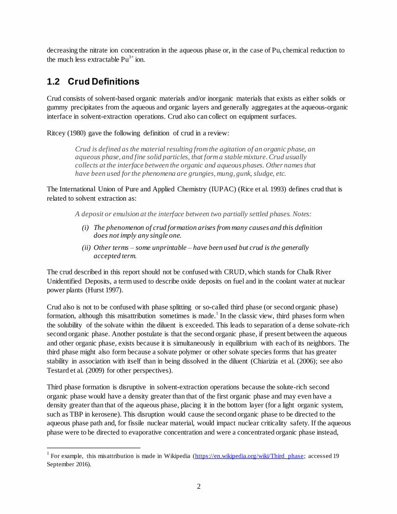
Figure 3. Di(2-ethylhexyl) Phosphoric Acid, HDEHP ................................................................. 5
Figure 4. Crud Formation for pH 6 Neodymium Chloride Extraction with 0.1 M HDEHP in Dodecane ......................................................................................................................... 5
Figure 5. Solubility of Silica in Nitric Acid (Elmer and Nordberg 1958; Felmy et al. 1994) ........... 8
Figure 6. Silica Gels Formed in Dissolution of K East Fuel Storage Basin Sludge ......................... 8
Figure 7. Hanford PUREX Process Flow Chart (Hanford, 1964) .................................................10
Figure 8. The Plutonium Finishing Plant (Teynor 2015) .............................................................20
Figure 9. Plutonium Reclamation Facility Cut-Away View Towards the Southeast ......................21
Figure 10. PRF Canyon Views, Looking South..........................................................................22
Figure 11. PRF Canyon Views in 2012 during Start of Equipment Demolition ............................23
Figure 12. Plutonium Processing Cycle at the PFP (Hoyt and Teal 2004) ....................................25
Figure 13. Plutonium Scrap from PFP at Hanford. Left – Sand, slag & crucible debris; Right – Pu metal turnings pressed into a “briquette” ca. 1954 ..............................................................28
Figure 14. Plutonium Scrap from Rocky Flats ...........................................................................30
Figure 15. Early PRF Flowsheet (Bruns 1960) ...........................................................................31
Figure 16. Perforated Plate (left) and Pulse Plate Cartridge String (right) (ARHCO 1976) ............34
Figure 17. Dibutyl Butyl Phosphonate (DBBP)..........................................................................35

1
1.0 Background
Solvent extraction using tributyl phosphate (TBP) has been practiced at the Hanford Site since 1952.
Extraction of uranium (U), plutonium (Pu), and, to a lesser extent, neptunium (Np) occurred at the
Hanford Site’s Plutonium Uranium Extraction (PUREX) Plant from 1956 until 1990. The extractant
initially was 30 volume percent (vol%) TBP dissolved in a select kerosene fraction. After 1966, normal
paraffin hydrocarbon (NPH) was the diluent. Extraction of U from acidified metal wastes remaining from
the Bismuth Phosphate Process using TBP occurred at the Uranium Recovery (or TBP) Plant from 1952
until 1958 and used 12.5 vol% TBP in kerosene diluent. Recovery of Pu from scrap by solvent extraction
using 15 to 23 vol% TBP in carbon tetrachloride (CCl4) diluent occurred in the RECUPLEX Process
(Recovery of Uranium and Plutonium by Extraction) at the Plutonium Finishing Plant (PFP) from 1955
until 1962. A subsequent 20 vol% TBP-in-CCl4 solvent-extraction process for Pu recovery occurred in the
Plutonium Reclamation Facility (PRF) beginning in 1964 and ending with a training run in 1994.
1.1 Extraction Using TBP
The charge-neutral U and Pu solvate species, [UO2(NO3)2∙2TBP]0 and [Pu(NO3)4∙2TBP]
0, shown below,
illustrate the “hard acid” qualities of the UO22+
and Pu4+
ions and their marked affinities for “hard base”
oxygen species in the nitrate ion, NO3-, for U, the actinyl oxygens (i.e., the axial oxygens on the uranyl
ion, O=U2+
=O), and, importantly for solvent extraction using TBP, the phosphoryl oxygen (i.e., on the
P=O moiety in TBP) arrayed around the actinide metal ions. The coordination number for U is eight,
including the actinyl oxygens, and ten for Pu. Note that the nitrate ions are coordinated to the actinides as
“short-bite” bidentate ligands.
[UO2(NO3)2∙2TBP]0 Solvate [Pu(NO3)4∙2TBP]
0 Solvate
Figure 1. Uranium(VI) and Plutonium(IV) Nitrate-TBP Solvate Species
The lipophilic natures of the respective solvate species are evident by the presence of eight normal butyl
groups emanating from the highly ionic, but charge-neutral and non-polar, inorganic metal-nitrate-
phosphate core. This lipophilicity allows solvation of the U and Pu solvate species in non-polar organic
diluents such as NPH and CCl4. Reversion of the actinide ions to the aqueous phase is achieved by
2
decreasing the nitrate ion concentration in the aqueous phase or, in the case of Pu, chemical reduction to
the much less extractable Pu3+
ion.
1.2 Crud Definitions
Crud consists of solvent-based organic materials and/or inorganic materials that exists as either solids or
gummy precipitates from the aqueous and organic layers and generally aggregates at the aqueous-organic
interface in solvent-extraction operations. Crud also can collect on equipment surfaces.
Ritcey (1980) gave the following definition of crud in a review:
Crud is defined as the material resulting from the agitation of an organic phase, an aqueous phase, and fine solid particles, that form a stable mixture. Crud usually collects at the interface between the organic and aqueous phases. Other names that have been used for the phenomena are grungies, mung, gunk, sludge, etc.
The International Union of Pure and Applied Chemistry (IUPAC) (Rice et al. 1993) defines crud that is
related to solvent extraction as:
A deposit or emulsion at the interface between two partially settled phases. Notes:
(i) The phenomenon of crud formation arises from many causes and this definition does not imply any single one.
(ii) Other terms – some unprintable – have been used but crud is the generally accepted term.
The crud described in this report should not be confused with CRUD, which stands for Chalk River
Unidentified Deposits, a term used to describe oxide deposits on fuel and in the coolant water at nuclear
power plants (Hurst 1997).
Crud also is not to be confused with phase splitting or so-called third phase (or second organic phase)
formation, although this misattribution sometimes is made.1 In the classic view, third phases form when
the solubility of the solvate within the diluent is exceeded. This leads to separation of a dense solvate-rich
second organic phase. Another postulate is that the second organic phase, if present between the aqueous
and other organic phase, exists because it is simultaneously in equilibrium with each of its neighbors. The
third phase might also form because a solvate polymer or other solvate species forms that has greater
stability in association with itself than in being dissolved in the diluent (Chiarizia et al. (2006); see also
Testard et al. (2009) for other perspectives).
Third phase formation is disruptive in solvent-extraction operations because the solute-rich second
organic phase would have a density greater than that of the first organic phase and may even have a
density greater than that of the aqueous phase, placing it in the bottom layer (for a light organic system,
such as TBP in kerosene). This disruption would cause the second organic phase to be directed to the
aqueous phase path and, for fissile nuclear material, would impact nuclear criticality safety. If the aqueous
phase were to be directed to evaporative concentration and were a concentrated organic phase instead,
1 For example, this misattribution is made in Wikipedia (https://en.wikipedia.org/wiki/Third_phase; accessed 19
September 2016).

3
“red oil” formation from nitration of the organic solvent and diluent could occur with energetic effects of
fire and explosion (Usachev and Markov 2003).

4
2.0 Crud Constituents
Crud exists in a variety of forms depending on the flowsheet step and stream compositions but consists of
three major constituents:
Organic extractants, their decomposition products, and their compounds. For TBP extractant-based
systems, crud includes the TBP radiolytic and hydrolytic degradation products dibutyl phosphate
(DBP) and monobutyl phosphate (MBP) – structures below – and their poorly soluble compounds
generally formed with highly hydrolyzable metal ions (e.g., ZrO2+
, Pu4+
). Cruds with TBP and metal
ions cannot be excluded but no evidence of their occurrence was found in the technical literature.
TBP DBP MBP
Figure 2. Tributyl Phosphate (TBP), Dibutyl Phosphate (DBP), and Monobutyl Phosphate (MBP) (DBP and MBP shown as their respective acid structures)
Silica-based gels (SiO2∙xH2O) and metal (hydr)oxides (e.g., Fe(OH)3, ZrO(OH)2) that collect at the
organic-aqueous interface.
Of great concern for process control and product throughput, undissolved nuclear material (e.g., Pu
oxide) that seeks the interface and thus becomes part of the crud.
2.1 Crud from Decomposition of TBP
Both chemical and radiolytic decomposition of TBP occur because of the respective effects of acid
hydrolysis in HNO3 (Burger 1955; Lloyd and Fellows 1985) and alpha and gamma radiation damage
(Barney and Bouse 1977; Lloyd and Fellows 1985; Gao et al. 2015). The decompositions in all cases
involve the stepwise loss of butoxy [-O(CH2)3CH3] groups as butanol, HO(CH2)3CH3, to make, in order,
DBP, MBP, and phosphate, PO43-
. When the solvent is properly maintained by alkaline cleanup steps in
the solvent-extraction process, which also remove the water-miscible butanol, decomposition beyond
DBP to MBP normally is not given an opportunity to occur.
Complexes from the interaction of DBP with polyvalent metal ions include Zr4+
(or ZrO2+
) but also Pu4+
and Pu3+
. The Pu(III,IV)-DBP complexes have high affinity for the TBP-kerosene (paraffin hydrocarbon)
organic phase in the PUREX process and the TBP-CCl4 organic phases in the PRF. Precipitation of
thorium(IV), chemically analogous to Pu(IV), as the compound Th(DBP)4 occurs and appears at the
interface between the organic and aqueous phases. This has led to the speculation that the analogous
Pu(DBP)4 will precipitate (Zimmer and Borchardt 1986).
5
2.2 Crud from Inorganic Solids
Finely divided solids such as silica gels and clays present in solvent-extraction systems also seek the
organic-aqueous interface and can create and stabilize emulsions that impede and ultimately thwart the
rapid organic-aqueous disengagement needed for successful solvent-extraction operations. The solids
appearing at the interface also can include undissolved solid plutonium dioxide, PuO2, and other Pu-
bearing solids. An image of interfacial crud formation occurring with increasing concentration of
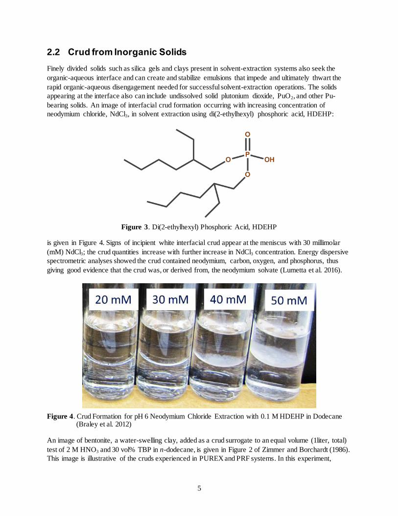
neodymium chloride, NdCl3, in solvent extraction using di(2-ethylhexyl) phosphoric acid, HDEHP:
Figure 3. Di(2-ethylhexyl) Phosphoric Acid, HDEHP
is given in Figure 4. Signs of incipient white interfacial crud appear at the meniscus with 30 millimolar
(mM) NdCl3; the crud quantities increase with further increase in NdCl3 concentration. Energy dispersive
spectrometric analyses showed the crud contained neodymium, carbon, oxygen, and phosphorus, thus
giving good evidence that the crud was, or derived from, the neodymium solvate (Lumetta et al. 2016).
Figure 4. Crud Formation for pH 6 Neodymium Chloride Extraction with 0.1 M HDEHP in Dodecane (Braley et al. 2012)
An image of bentonite, a water-swelling clay, added as a crud surrogate to an equal volume (1liter, total)
test of 2 M HNO3 and 30 vol% TBP in n-dodecane, is given in Figure 2 of Zimmer and Borchardt (1986).
This image is illustrative of the cruds experienced in PUREX and PRF systems. In this experiment,

6
around 90% of the 50 milligrams of added bentonite reported to the interfacial crud. Interfacial cruds
similar to that shown by bentonite also were prepared using silica. A test similar to that described for
bentonite, with ~25-μm diameter silica having 41 m2/g specific surface area, produced an interface crud
comprised of 5-mm diameter drops of organic phase within a continuous aqueous phase. With finer silica
(~17-μm diameter; 235 m2/g specific surface area), an organic-in-aqueous emulsion with smaller organic
droplets was formed.
Thus, cruds are manifest as stable emulsions at the aqueous-organic interface. The emulsions can be
bulky, combining appreciable fractions of the organic and aqueous phases. These emulsions can block or
retard the coalescence and formation of the cleanly separate organic and aqueous phases necessary for
successful solvent extraction.
The type of emulsion (water-in-oil or oil-in-water) depends on the different degrees to which the crud-
forming fines are wetted by the organic and aqueous phases. In an oil-in-water emulsion, partially
hydrophobic (and partly lipophilic; i.e., amphiphilic) fine solids are adsorbed on, and coat, droplets of the
oil (organic) phase. The emulsion is stabilized because the coating of fines inhibits coalescence of the oil
droplets. Conversely, fine solids that are partially hydrophilic (again, amphiphilic) coat droplets of the
aqueous phase and thus inhibit aqueous phase coalescence. In either instance, the stability of the coated
droplets inhibits coalescence. However, solids that are extremely hydrophilic or lipophilic are not
prospective crud formers because they are completely wetted by the aqueous or organic phase,
respectively, and thus are not prone to report to the aqueous-organic phase boundary. For instance, as
observed by Zimmer and Borchardt (1986), Teflon powder, being extremely hydrophobic and lipophilic
partitions to the organic phase and does not stabilize an aqueous-organic emulsion.
Zimmer and Borchardt (1986, and references therein) describe a method to identify whether the emulsion
is oil-in-water or water-in-oil. In this method, sudan red, an oil-soluble dye, and malachite green, a water-
soluble dye, are mixed with talc and the mixture spread on a filter paper. The emulsion then is fed to the
“painted” filter paper in a dropwise fashion. The continuous phase from the emulsion, being more mobile,
spreads radially more rapidly than the discontinuous droplets. Therefore, its identity is indicated by its
filial dye color – red if organic, green if aqueous – moving more rapidly away from the drop spot. Based
on this testing, Zimmer and Borchardt (1986) found that the silica and bentonite cruds were oil-in-water
emulsions whereas the ZrO(DBP)2 and Th(DBP)4 were water-in-oil. Presumably, Pu(IV)-DBP would also
form a water-in-oil crud.
Sources of silica in the crud could include residues that were not completely removed from the dissolvers
following the chemical dissolution of the fuel cladding (for PUREX). At Hanford, two types of cladding
dominated (Kupfer et al. 1999). For the first eight Hanford production reactors (B, C, D, DR, F, H, KE,
and KW), the fuel cladding was aluminum with an aluminum-silicon (AlSi) alloy bonding agent between
the cladding and uranium fuel slug. The cladding was removed from the fuel by dissolution in a sodium
hydroxide / sodium nitrate (NaOH/NaNO3) solution. The denuded uranium metal fuel slugs then were
rinsed and then dissolved in nitric acid with the solution to be fed to solvent extraction. For the remaining
Hanford production reactor, N, the fuel cladding was Zircaloy (98.5% zirconium, 1.5% tin) and the
cladding was dissolved in an ammonium fluoride / ammonium nitrate (NH4F/NH4NO3) solution. The
denuded uranium metal fuel slugs following decladding were rinsed, and the slugs dissolved in nitric acid
for solvent-extraction processing. Incomplete rinsing after the chemical decladding steps thus would leave
aluminum and silicon or zirconium and tin, respectively, in the solutions destined for solvent extraction.
These four metals (i.e., Al, Si, Zr, and Sn) are highly hydrolyzable, are found in interface cruds, and

7
easily could have found their way to solvent-extraction operations by incomplete rinsing of the
decladding solution.
Another potential source of crud is through acid attack of infiltrated air-borne soil (for PUREX,
RECUPLEX, and PRF) and silicate-bearing scrap at the PFP. The response of silicate minerals to acid
attack follows three potential pathways – congruent dissolution to release the silica and the
complementary cationic elements (e.g., aluminum, calcium, etc.) to solution in parallel fashion,
incongruent dissolution, in which the silica remains in the solid phase while many or most of the
complementary cationic elements dissolve, and essentially no dissolution (Terry 1983a). In general,
congruent dissolution is observed for silicate minerals in which the silica is present as an independent
orthosilicate (SiO44-
monomer), pyrosilicate (Si2O76-
dimer), or ring silicate (Si3O96-
, Si4O128-
, or Si6O1812-
;
trimer, tetramer, and hexamer, respectively). In contrast, the “infinite” silicates, with long-range repeating
silicate structural units – the inosilicates (chain-like), phyllosilicates (layer-like), and tectosilicates
(framework) – show partial or little dissolution of the underlying silica and leave silica-rich undissolved
residues after acid contact. However, sufficient substitution of other ions, typically Al3+
or Fe3+
, into the
“infinite” silicate sites can allow breakdown of even these minerals in acid with behaviors approaching
congruent dissolution. Conversely, ortho-, pyro-, and ring silicates that ordinarily would be expected to
dissolve congruently, but have complementary cationic elements of high ionic potential (charge density)
such as Be2+
and Zr4+
, can resist acid leaching.
Another potential source of crud is through acid attack of infiltrated air-borne soil (for PUREX,
RECUPLEX, and PRF) and silicate-bearing scrap at the PRF. Dissolution of many silicate minerals
occurs readily in acid (Terry 1983a). But once dissolved, the silica soon reaches saturation, about 10-3
M
(Figure 5), and precipitates as a gel. Such gels are depicted in Figure 6, generated in this case from
Hanford soil present in fuel storage basin sludge upon exposure to boiling nitric acid (Schmidt et al.
1999). It is seen that silica solubility decreases with increasing nitric acid concentration and decreasing
temperature. Therefore, fuels dissolution, which generally takes place at boiling temperatures, would lead
to increasing precipitation with cooling to solvent extraction processing temperatures. Precipitation
because of increase in nitric acid concentration generally would not occur because dissolution operations
are designed to reach target nitric acid and uranium concentration values upon full dissolution. As noted
by (Terry 1983b), these gels impact hydrometallurgical processing in many areas including recovery of
dissolved metal values from voluminous siliceous solids, rinsing of the siliceous solids, and fouling of ion
exchange resins as well as in crud formation in solvent extraction operations.

8
Figure 5. Solubility of Silica in Nitric Acid (Elmer and Nordberg 1958; Felmy et al. 1994)
Figure 6. Silica Gels Formed in Dissolution of K East Fuel Storage Basin Sludge. Left – Suspended gels in ~500 mL of sludge dissolved in initially 6-M HNO3. Right – Gels adhering to ~3-mm diameter temperature probe (gels readily removed by rinsing) (from Figures A.2.C and A.5 of Schmidt et al. (1999))

9
2.3 Undissolved Plutonium-Bearing Solids in Crud
As will be shown in subsequent discussions on PRF plant experience, the solids appearing at the interface
also can include undissolved solid plutonium dioxide, PuO2, and other Pu-bearing solids, such as
PuF4∙2.5H2O, from scrap processing.
The remainder of this report will focus on the three crud categories, their properties, and their effects on
PUREX extractions and on those specific to plutonium recovery performed at the PRF within the PFP on
the Hanford Site based on investigations reported in the Hanford Site technical literature.
10
3.0 PUREX Crud
PUREX was first tested on a lab scale pilot plant at Oak Ridge National Laboratory from 1950-1952. It
was then implemented on an industrial scale in 1954 at F-Canyon at Savannah River and shortly after (in
1956) on the Hanford site(Hurst 1997).
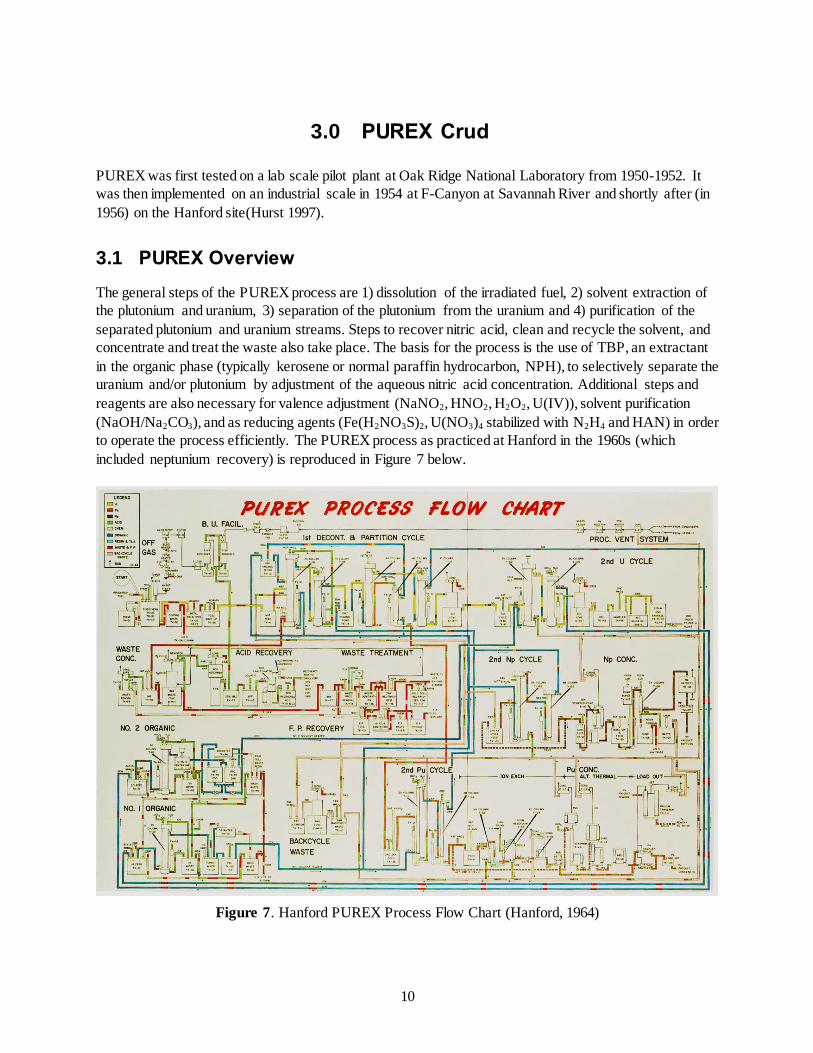
3.1 PUREX Overview
The general steps of the PUREX process are 1) dissolution of the irradiated fuel, 2) solvent extraction of
the plutonium and uranium, 3) separation of the plutonium from the uranium and 4) purification of the
separated plutonium and uranium streams. Steps to recover nitric acid, clean and recycle the solvent, and
concentrate and treat the waste also take place. The basis for the process is the use of TBP, an extractant
in the organic phase (typically kerosene or normal paraffin hydrocarbon, NPH), to selectively separate the
uranium and/or plutonium by adjustment of the aqueous nitric acid concentration. Additional steps and
reagents are also necessary for valence adjustment (NaNO2, HNO2, H2O2, U(IV)), solvent purification
(NaOH/Na2CO3), and as reducing agents (Fe(H2NO3S)2, U(NO3)4 stabilized with N2H4 and HAN) in order
to operate the process efficiently. The PUREX process as practiced at Hanford in the 1960s (which
included neptunium recovery) is reproduced in Figure 7 below.
Figure 7. Hanford PUREX Process Flow Chart (Hanford, 1964)

11
3.2 Crud Detailed in PUREX during Hanford Operations
The first PUREX technical manual was written in 1955, the year prior to the plant startup at Hanford.
Therefore it is likely that observations recorded and guidance provided therein were learned during
laboratory-scale testing at Oak Ridge National Laboratory and full-scale operation of F-Canyon at
Savannah River.
3.2.1 1955 PUREX Technical Manual
The phenomenology of crud and its highly associated manifestations in PUREX processing is provided in
the 1955 PUREX Technical Manual (HAPO 1955). The following description summarizes the
manifestations as arising from a combination of solvent breakdown products complexing dissolved
metallic impurities and/or solid impurities introduced by process chemicals (and fuel and process vessel
corrosion, as detailed later) and the association of gamma-active fission products with the crud solids.
Chapter V. Section H.2. “Crud” Formation
Interface “crud” is the informal name given to the brownish-black solids which tend to collect at the liquid-liquid interface in the solvent-extraction columns after prolonged column operation. The exact nature of this material is not known, but it is believed that the solids are either impurities brought in by the feed or that they are formed in the columns by combination of dissolved metallic impurities with solvent decomposition products to form insoluble compounds. Representative samples of the crud have shown it to contain Fe, Al, and Si in varying proportions with lesser amounts of such elements as Ca, Ba, Mn, Mg, Cr, and Ni present.
Samples of crud removed from “hot” columns have shown considerable gamma activity from adsorbed or combined fission products. A typical breakdown of a crud sample from the Redox-Plant 2D column attributed 10 per cent of the gamma activity to Ru, 30 per cent to Zr, and 60% to Nb.
(21n) Entrainment of this crud in the product
streams (which may occur rather easily since its apparent density is between that of the aqueous and organic phases) would have the effect of reducing the decontamination factor obtained in the column.
Because of the possibility of fission-product carry-over by crud entrainment and the emulsion-stabilizing characteristics of crud components, provisions have been made to remove the crud from the column and to minimize the chances of its formation. Interface jet-out facilities are provided on all but the 2A, 2B and O-type columns to permit periodic cleanup of the interface. Solids are removed from the feed and extractant streams by centrifugation, while solids larger than 0.04 in. in diameter are removed from “cold” streams by screens. Solvent decomposition products are removed by the solvent treatment procedure described in Chapter IX (HAPO 1955, pages 582 through 583).
Crud can also contribute to emulsification of the aqueous and organic phases, retarding or completely
thwarting the phase disengagement needed for successful solvent-extraction operations. Potential
contributions from the organic diluent also are discussed.
Chapter V. Section H.3.2 Emulsifying impurities

12
Potential emulsifying agents include the decomposition products of TBP, particularly DBP, introduced in the solvent and colloidal alumina- or siliceous material introduced in the feed or as an impurity of “cold” chemical solutions. Other colloidal or gelatinous compounds, containing such metallic elements as Al, Fe, Sn, Ca, Ba, Mn, Mg, Cr, fission products, etc., have been identified either as potential emulsifying agents or as constituents of emulsion-stabilizing interface “crud”. These compounds may be formed in the column by combination of the metallic ions with the acidic decomposition products of TBP or with unsaturated hydrocarbon impurities in the TBP diluent. The metallic ions introduced to the system may come from the uranium slugs, concentrator corrosion, or “cold” chemical impurities. (HAPO 1955, page 585)
References are also made to emulsifying agents within the organic and aqueous phases and their
outcomes resulting from the existence of crud, which have the following deleterious effects in process
operation:
Chapter V. Section H.3.3 Effects of emulsifying agents on column performance
The effects of emulsifying agents on column performance have been sketched briefly in Subsections H 3.l and 3.2. These effects may be summarized as follows:
(a) Emulsification: may result in decreased capacity, reduced frequency limits for good performance, and impaired extraction.
(b) Entrainment: may cause increased solvent losses and fission-product carry-over in the organic product streams.
(c) Interface foam: may interfere with interface control; may result in increased entrainment; may result in flooding if interface emulsion is allowed to grow into plate or packed section.
(d) Interface “crud”: may result in increased fission-product carry-over on entrained “crud” (HAPO 1955, page 585).
Chapter VI. Section E.3. Emulsion
Excessive emulsification in the plate or packed section of a pulse column at otherwise favorable operating conditions may result from the presence of excessive concentrations of TBP hydrolysis products (DBP and MBP) or some types of siliceous and other foreign materials (“crud”), and is often accompanied by a foaming and improper phase disengagement in the column disengaging sections, particularly at the interface end (HAPO 1955, page 614).
Effects of DBP and MBP and of butanol and phosphoric acid are further elaborated:
Chapter IX. Section A.2.1. TBP degradation products
As discussed in Chapter IV, the rate of hydrolysis of TBP is apparently first order with respect to TBP concentration, and increases with increasing temperature and nitric acid concentration. Under the operating conditions of the Purex flowsheet, DBP is

13
formed to the extent of 10 to 20 p.p.m. of solvent while passing through the solvent-extraction columns, and complexes almost immediately with uranium or other metallic ions present. Since the complexes are more soluble in solvent than in aqueous solutions, at least 90% of the DBP formed is carried by the solvent to the solvent recovery facilities,
(2) where it is removed by the alkaline wash. MBP is formed in
smaller quantities than DBP, since it is a product of the hydrolysis of DBP and has a higher rate of hydrolysis than DBP. MBP is largely removed from the system via the aqueous wastes, although, some forms “cruddy” metallic precipitates, which are entrained in the solvent; these solid complexes are removed from the column interfaces by special jets and from the solvent by alkaline washing and centrifugation. Phosphoric acid and butanol are formed in still smaller quantities and are removed (principally in the aqueous wastes) as rapidly as formed.
The presence of DBP, MBP, and butanol may affect the Purex process in many ways. (3,4,22)
DBP forms stable complexes with uranium and plutonium nearly stoichiometrically, and with fission products. These complexes strongly favor the solvent. DBP may, therefore, cause high uranium and plutonium losses in organic waste streams and a high radioactivity level in the solvent; although the fission-product complexes strongly favor the solvent; sufficient stripping occurs in the C-type columns to decrease the decontamination obtained in the solvent-extraction cycle. The principal process effects of MBP are those resulting from the formation of metal-organic complexes. These complexes can cause high product losses by preventing normal solvent extraction and also form surface-active agents which promote maloperation through excessive entrainment and/or emulsification. Butanol can adversely affect beta decontamination and/or cause plutonium losses by reducing Pu(IV) to Pu(III),
(27); but the concentrations required to cause observable effects are
rarely encountered in Purex processing (HAPO 1955, page 903).
The most prominent of the fission products reporting to the crud are niobium and zirconium:
Chapter IV. Section A.3.4. Decontamination from fission products
Zirconium normally contributes about 1/10 of the gross beta and l/3 of the gross gamma activity of the feed; niobium about 1/100 of the gross beta and l/3 of the gross gamma activity. Niobium and zirconium exhibit some tendency to be adsorbed on solids. High radioactivity levels sometimes associated with solids accumulated at the aqueous-organic interface in the column (“crud”) are usually largely due to Nb and Zr (HAPO 1955, page 416).
Although the crud is present at the aqueous-organic interface in the PUREX solvent-extraction process,
the crud shows evidence of being lipophilic as it is attracted to Raschig rings made of fluorothene (-
CF2CFCl- polymer) while not being attracted to stainless steel Raschig rings:
Chapter V. Section D.7.1. Extraction Section
One advantage of stainless-steel Raschig rings is that, being preferentially wetted by the aqueous phase, they permit the interface to be maintained in the more convenient, top position. On the other hand, a bottom interface position (used with the fluorothene rings) possesses the advantage of precluding carry-over of interfacial “crud” into the product (2AP) stream (HAPO 1955, page 550).
14
3.2.2 1980 PUREX Technical Manual
Later versions of the PUREX Technical Manual, 1980 and 1989 (Moore et al. 1980; WHC 1989b),
reiterate many of the crud related details first mentioned in 1955. Thus, in the 1980 version (Moore et al.
1980), the following is stated regarding emulsification:
Chapter IV. Section 4.4.11.2.3. Emulsion
Excessive emulsification in the plate section of a pulse column at otherwise favorable operating conditions may result from the presence of excessive concentrations of TBP hydrolysis products, dibutyl phosphate (DBP) and monobutyl phosphate (MBP), or some types of siliceous or other foreign solid materials (crud). Emulsification is often accompanied by foaming and improper phase separation in the column disengaging sections, particularly at the interface end (Moore et al. 1980, page 4-81).
The following text is a practically verbatim restatement of the text appearing in Section IX of the 1955
PUREX Technical Manual:
Chapter IV. Section 4.7.1.1 Tributyl Phosphate Degradation Products
The rate of hydrolysis of TBP is apparently first order with respect to TBP concentration, and increases with increasing temperature and nitric acid concentration. Under the operating conditions of the Purex flowsheet, DBP is formed while passing through the solvent extraction columns, and complexes almost immediately with uranium or other metallic ions present. Since the complexes are more soluble in solvent than in aqueous solutions, at least 90% of the DBP formed is carried by the solvent to the solvent recovery facilities, where it is removed by the solvent washes. Monobutyl phosphate is formed in smaller quantities than DBP, since it is a product of the hydrolysis of DBP, and has a higher rate of hydrolysis than DBP. Monobutyl phosphate is largely removed from the system via the aqueous wastes, although some forms cruddy metallic precipitates, which are entrained in the solvent. These solid complexes are removed from the solvent by washes in the solvent treatment system. In addition, some of the crud accumulates at the solvent extraction interface from where it is periodically removed by special interface jets.
Phosphoric acid and butanol are formed in still smaller quantities, and are removed (principally in the aqueous wastes) as rapidly as they are formed. Butanol can adversely affect beta FP decontamination and/or cause plutonium losses by reducing plutonium(IV) to plutonium(III) (Ref. 11), but the concentrations required to cause observable effects are rarely encountered in Purex processing (Moore et al. 1980, page 4-135).
The description of location of the phase boundary, selection of the continuous and dispersed phases and
their flow rates, and achievement of the selected continuous phase by pulse plate (or packing) design and
material according to wetting characteristics are new in the 1980 PUREX Technical Manual (with regards
to the 1955 version):
Chapter VI. Section 6.2.3.3.2 Plate or Packing Wetting Characteristics and Choice of Continuous Phase

15
The trend of increasing HTU (2)
values with increasing continuous-to-dispersed phase flow ratio is attributed to the decrease in the interfacial contact area as the relative flow of the dispersed phase decreases. Thus, other factors being equal, slightly improved extraction efficiency may result if the phase with the larger flow rate is dispersed in the phase with the smaller flow rate. In this case, the advantage, which sometimes does not occur at all, depends upon the perforated plates being wetted by the continuous phase. With plates preferentially wetted by the dispersed, rather than the continuous phase, HTU values are generally higher. (The wetting characteristics of various materials used for perforated plates are presented in 6.1.3.8.3.) Visual observation of the dispersion in small-scale glass columns confirms the above effects. When the sieve plate (or packing) is preferentially wetted by the dispersed phase, it coalesces on the plates and travels through the column in large streams or globs, rather than dispersing as small drops of fairly uniform size and much larger interfacial area.
A second criterion for the choice of continuous phase, which generally has been found to override the phase ratio considerations discussed above, is that the interface should be located at the waste end of the column. When operating in this manner, interface “crud” (an accumulation of siliceous, degraded organic and other materials) leaves the solvent extraction column with the raffinate stream, rather than following the product through the remainder of the process. Since the interface crud contains substantial amounts of adsorbed fission products, the decontamination performance would be severely reduced if the interface crud followed the product stream.
The above phenomenon was experienced in the Purex Plant immediately after the initial “hot” startup. The A-type columns (except for the 2A column) were operated with the aqueous phase continuous and the C-type columns (except for the 2B column) were operated with the organic phase continuous. Satisfactory decontamination performance was achieved only after the A- and C-type columns were replaced with ones designed for operation with the organic and aqueous phases continuous, respectively (Moore et al. 1980, page 6-154).
Further descriptions of the selection of materials (in part as a result of crud effects), including stainless
steel and fluorothene, for column plates are described in:
Chapter VI. Section 6.2.4.2 Development of the A-Type Column Design
Poor fission product decontamination performance was experienced with the A-type columns immediately after processing of irradiated fuel commenced. The poor performance was attributed to a combination of backmixing in the scrub section and “bleeding” of interface crud into the product stream. This problem was corrected by changing to organic phase - continuous operation, with the interface located at the raffinate end of the column. This change required the replacement of the A-type columns with ones equipped with interface controllers in the lower disengaging sections, and with cartridges capable of operation with the organic phase continuous. Nozzle plate cartridges were selected for the extraction sections, based on development studies which showed them to provide superior performance under nearly all conditions, but particularly with the organic phase continuous (Ref. 161). Numerous cartridge designs were investigated for use in the scrub sections, with the
(2) HTU is Height of Transfer Unit, a measure of the column height needed to achieve a certain degree of solvent
extraction separation.

16
most promising appearing to be the mixed-plate, or “zebra,” designs. A cartridge comprised of alternate groups of four stainless steel and two linear polyethylene plastic
+ plates on a 1-inch spacing was recommended for the HA scrub section ( Ref.
161). This cartridge gave good performance, but the plastic plates deteriorated rapidly, breaking up into small pieces that jammed flow meters and plugged valves.
+ The material specified for the plastic plates used in Purex Plant pulse columns is
poly-trifluoromonochloroethylene. Two brands of this material, which have been used with equal success, are Kel-F, manufactured by the M. W. Kellogg Company and Fluorothene, manufactured by E. I. DuPont de Nemours and Company. Linear polyethylene was specified for some of the early replacement cartridges because of its superior resistance to radiation damage, but was found to be extremely susceptible to “environmental embrittlement” and cracking (believed to be caused by exposure to oxygen and/or polar solvents) and thus unsatisfactory for use in the Purex Plant pulse columns (Moore et al. 1980, page 6.160).
The following description of “Special Problems” from the 1980 PUREX Technical Manual is similar to Section of the 1955 PUREX Technical Manual but has sufficient additional information to be worthwhile quoted in its entirety:
Chapter VI. Section 6.2.7. Special Problems
This subsection discusses briefly the experimental information available on inextractable uranium and plutonium, crud formation, emulsifying impurities and emulsification, and pulse loss or distortion. In unusual circumstances, such conditions may give rise to anomalous column behavior, but generally, their effects are minor and do not cause any operational problems.
6.2.7.1 “Inextractable” Uranium and Plutonium
Both MBP and DBP, decomposition products of TBP, as well as some other elements and compounds form stable complexes with uranium and plutonium. The complex formed with MBP is strongly aqueous-favoring and only sparingly soluble in Purex aqueous and organic streams. Any MBP present in the organic extractant or formed by hydrolysis of DBP in the solvent extraction columns will carry out a corresponding amount of uranium and/or plutonium in the aqueous raffinate. The uranium-MBP complex is a fine, possibly colloidal, precipitate and may collect at the interface temporarily, but will eventually exit with the aqueous raffinate stream. The complex formed with DBP, on the other hand, is strongly organic-favoring and will leave the solvent extraction system in the organic raffinate streams. Other chemicals which form strong, aqueous favoring complexes with uranium and/or plutonium, and thus cause high waste losses, include fluoride, oxalate, sulfate and phosphate ions. The uranium and plutonium complexed in this manner and leaving the columns in the raffinate streams is referred to as “inextractable” or “unstrippable,” as the degree of extraction or stripping of these complexes is very small because of their unfavorable distribution ratios.
6.2.7.2 “Crud” Formation
Interface “crud” is the colloquial name given to the brownish-black solids which collect at the liquid-liquid interface in the solvent extraction columns. The exact composition of this material is not known. Analysis of representative samples of the crud, however, have shown it to contain iron, aluminum, and silicon in varying

17
proportions, with lesser amounts of such elements as calcium, barium, manganese, magnesium, chromium, and nickel. Radioactive constituents consist largely of ruthenium, zirconium and niobium. Entrainment of this crud in the product streams (which could occur rather easily since its apparent density is between that of the aqueous and organic phases) would have the effect of reducing the decontamination factor obtained in the column. For this reason, the Purex Plant solvent extraction columns are designed with the interface position at the waste end of the column. Thus, the entire length of the column is available to scrub the interface crud out of the product stream, and any carryover will be with the raffinate stream.
6.2.7.3 Emulsions
Effective extraction performance of a pulse column is dependent on the formation of a relatively fine phase dispersion to provide a large interphase contact area. It is an additional requirement, however, that the dispersion formed in the column should be capable of disengaging fairly readily. Emulsions which do not disengage readily may be responsible for the following undesirable effects:
Decreased capacity, reduced pulse frequency rates for good performance, and reduced extraction efficiency;
Increased organic solvent losses and fission product carryover in the organic product streams;
Interface foam may interfere with interface controls, increase entrainment, and cause flooding if the foam is allowed to propagate into the plate section.
A discussion of the above effects and their possible causes follows.
6.2.7.3.1 Emulsification, Interface Foam, and Entrainment
Occasionally, because of the chemical flowsheet conditions, excessive pulsing, or the presence of emulsion-stabilizing impurities, the net rate of emulsion formation in the column, or a portion of the column, is greater than the rate of dissipation of the emulsion. If the accumulation of emulsion continues until an appreciable amount of the discontinuous phase is entrained in the continuous phase effluent, the column is said to be emulsified or flooding by emulsification.
Interface foam is produced when the dispersed phase fails to coalesce when it reaches the interface. The foam (or partially stabilized emulsion) may accumulate to a stable height, or it may propagate throughout the plate section, eventually producing flooding by emulsification. Two types of interfacial foam have been observed: a simple type in which droplets of one phase are dispersed in the other phase, and a more complex type in which thin, filmy "balloons" of one phase are both filled and surrounded by the other phase. The latter type of emulsion is believed to give the frothy appearance to the top layer of the normal, slight amount of interface foam in the aqueous-continuous columns. Excessive interface foam may be produced by emulsion stabilizing impurities which collect at the interface.
Entrainment refers to the carryover of one of the phases with the effluent stream of the other phase. The entrained liquid normally amounts to only a small fraction (typically, 0.01 to 0.10) of the total flow of the phase, and usually consists of very fine droplets, some of which may be colloidal in size, which usually do not settle out in

18
disengaging sections. An emulsifying agent in the column would be expected to increase the amount of entrainment. Entrainment is undesirable for the following reasons:
Entrainment of the organic phase in the aqueous effluents represents a potentially economically important loss of solvent, and adds an additional stripping load to the uranium and backcycle concentrators. Some of the solvent may be recovered in the condensate recycle system, but would likely contain decomposition products that would have an adverse effect on solvent extraction performance.
Entrainment of the aqueous phase in the organic product streams may, in some instances, permit the carryover of fission products to subsequent extraction cycles.
6.2.7.3.2 Emulsifying Impurities
The presence of any emulsifying impurities in the pulse columns may intensify any or all of the undesirable effects discussed in this subsection. Potential emulsifying agents include the decomposition products of TBP (particularly DPB) introduced in the solvent, and colloidal alumina or siliceous material introduced in the feed or as an impurity in "cold" chemical solutions. Other colloidal or gelatinous compounds, containing such metallic elements as aluminum, iron, tin, gallium, barium, manganese, magnesium, chromium and fission products, have been identified either as potential emulsifying agents or as constituents of emulsion-stabilizing interface crud. These compounds may be formed in the column by combination of the metallic ions with the acidic decomposition products of TBP, or with unsaturated hydrocarbon impurities in the TBP diluent. This latter mechanism is not likely, however, with the use of n-dodecane or a similar highly refined normal paraffin hydrocarbon. The metallic ions introduced to the system may come from the uranium fuel elements, concentrator corrosion, or "cold" chemical impurities.
Primary reliance on elimination of emulsifying impurities in the Purex Plant rests on the solvent treatment system and on the purity specifications for the chemicals procured (Ref. 7).
6.2.7.3.3 Emulsion-Induced Instability
Excessive emulsification, which would result in unstable operation or flooding, may normally be prevented without impairment of HTU values by the proper selection of pulsing conditions and superficial volume velocities for the chemical system and column design involved. However, under unusual conditions not normally encountered in the Purex Plant, special problems in this respect may arise as a result of large differences in the ease of phase dispersion in the different portions of the column. In such cases, the most easily dispersed portion of the column system may be susceptible to emulsion-induced instability at the pulsing conditions required to produce reasonably good performance in less easily dispersed portions.
Emulsion-induced instability effects sometimes do not arise immediately upon establishment of operating conditions susceptible to their occurrence. At borderline conditions, the column may operate stably for hours until an accumulation of emulsifying impurities, abrupt changes in interface position, or flow rate fluctuations
19
catalyze the development of instability. The instability usually takes the form of large globs (approximately 1 to 2 inches in diameter) of coalesced dispersed phase, which channel through the tightly “packed” emulsion in the unstable region. In extreme cases, cyclic local phase inversion, or even complete flooding, may result. In any case, extraction efficiency is likely to be reduced as a result of coalescence and channeling of the dispersed phase (Moore et al. 1980, pages 6-190 through 6-193).
3.2.3 1989 PUREX Technical Manual
Similar statements about crud and its impacts are expressed in the 1989 version of the PUREX Technical
Manual (WHC 1989a) as were given in prior versions of the manual. The following text describes the
effects of crud on emulsification.
Section 4.4.11.2.3. Emulsion
Excessive emulsification in the plate section of a pulse column at otherwise favorable operating conditions may result from the presence of excessive concentrations of TBP hydrolysis products, dibutyl phosphate (DBP) and monobutyl phosphate (MBP), or some types of siliceous or other foreign solid materials (crud). Emulsification is often accompanied by foaming and improper phase separation in the column disengaging sections, particularly at the interface end (WHC 1989b, page 4-78).
Information on TBP degradation products is further addressed in Section 4.7.1.1 of the 1989 PUREX
Technical Manual but the text is virtually identical with that given in the two prior versions of the Manual
and, in fact, refers directly to the 1955 version. Hydrolysis of TBP is considered in more detail in Section
6.1.3.1.4.1, “Hydrolysis,” of the 1989 version but the text is similar to that found in the 1980 Manual.

20
4.0 Plutonium Reclamation Facility Crud
This section presents experience with crud from operations of the Plutonium Reclamation Facility (PRF)
on the Hanford Site based on findings gathered from external and internal technical literature for both
PRF and the related predecessor facility, RECUPLEX (Judson 1958).
4.1 PRF Overview
Both PRF and RECUPLEX operated at PFP to recover plutonium from various solution and solid scrap
streams. Each process used ≈20 (15-23) vol% TBP as the solvent and had carbon tetrachloride, CCl4, as
the diluent. Both processes extracted tetravalent plutonium, Pu(IV), from an aqueous phase based on
nitric acid, HNO3. The PFP also was loosely known as “234-5” (Building; the 234 and 235 Buildings
merged, in fact, thus constituting the 234-5 designation), “234-5Z” to indicate the location of the plant in
the Z Area, “Z Plant,” and “Dash 5” but also takes in the PRF (236-Z), the Americium Recover Facility
(242-Z), and the Ventilation Building and Stack (291-Z) – see Figure 8.
Figure 8. The Plutonium Finishing Plant (Teynor 2015)
The PRF was a concrete canyon building which featured so-called “pencil tanks” and pencil-shaped
process vessels, including cylindrical solvent-extraction columns, of narrow (≈6-inches or smaller)
diameter for nuclear criticality safety. The cut-away cartoon view of the PRF shown in Figure 9 indicates
the central “”Process Cell” space and surrounding services including the “Miscellaneous Treatment
Room” where plutonium-bearing scrap solids dissolution operations occurred within six gloveboxes.
Operations of the columns occurred manually through the “Process Glove Boxes” whose windows also
N

21
allowed observation of the glass-walled solvent-extraction column performance. Such observations would
include organic/aqueous phase disengagement, formation of organic/aqueous emulsions, frothing, solids
entrainment, and leaks. Four main glove boxes were located on both sides of the canyon on the first two
floors. The entire glove box length was 240 feet and about 8 feet high. Equipment in the process cell was
mounted on the east and west walls of the canyon, leaving a cavernous interior space allowing movement
of retired and replacement equipment by the ceiling-mounted remotely operated bridge crane. The crane
movement could be viewed through windows at the second and third floors of the canyon (Gerber 1997).
Figure 9. Plutonium Reclamation Facility Cut-Away View Towards the Southeast
Photos of the interior of the PRF canyon just before commencement of hot operations (which occurred
May 6, 1964 (Gerber 1997)); and in 2004 are shown in Figure 10. Views taken in 2012 at the
commencement of demolition of the interior process vessels in the PRF canyon are shown in Figure 11.

22
Figure 10. PRF Canyon Views, Looking South. Top – November 1963, Before Hot Operations (Hanford photo N07994697). Bottom – September 2004, Panorama (photos courtesy of TJ Venetz)

23
Figure 11. PRF Canyon Views in 2012 during Start of Equipment Demolition. Top – View Looking South. Bottom – Pencil Tank Array on East Wall. Still images taken from DI-0001498_-_PRF_Story_2012_Video (1).wmv.
4.2 Process Flows
The nitric acid-based Pu feed to the PRF arose from scrap solutions generated during processing (e.g.,
filtrates from Pu oxalate precipitation) and dissolution or reconstitution of Pu-bearing solids scrap, much

24
of which was generated by Pu conversion and fabrication operations at the PFP. However, much of the
feed also included solid scrap from other Sites including the Rocky Flats Plant, the Savannah River Site,
the Lawrence Livermore National Laboratory, and the Los Alamos National Laboratory. Plutonium-
bearing materials also came from the United Kingdom under barter programs (Gerber 1997).
The block flow diagram for PFP scrap recycle and purification operation portions is shown in the middle
of Figure 12, centered on the “Solvent Extraction Purification” (i.e., RECUPLEX and PRF) space
enclosed in dashed lines, and illustrates only the in-plant sources. The indigenous scrap streams
diagrammed in Figure 12 entering the “Solvent Extraction Purification” block are all impure nitrate
solutions and exited purification as “pure nitrate” for shipment (rarely) or as input to the conversion
process sequence shown at the top of the diagram. The conversion processes at the PFP had various end-
points including Pu metal parts for weapons, Pu metal for shipment offsite for weapons fabrication at the
Rocky Flats Plant, and Pu oxide for mixed oxide fuels and for storage. In Figure 12, the “Foundry” (Task
IV) and “Fabrication, Coating, Cleaning, inspection (Tasks V-VIII)” refer to Pu weapons part
manufacturing. Processing for weapons parts ended in 1965 (Gerber 1997).

25
Figure 12. Plutonium Processing Cycle at the PFP (Hoyt and Teal 2004)


PNNL-25888
27
4.3 Hanford-Sourced Scrap
As seen in Figure 12, the impure nitrate solution feed sources included:
The “Filtrate Concentrator” for treated filtrates from the Pu(IV) oxalate precipitation process.
Treatment necessarily included destruction of oxalate and oxalic acid, usually with permanganate,
MnO4- oxidant/catalyst, or with extended hot concentrated nitric acid oxidation.
The “Sand, Slag, and Crucible Dissolvers,” i.e., SS&C (or S&C), which is scrap from the
calciothermic reduction of Pu tetrafluoride (PuF4) by calcium metal. The SS&C contained magnesium
oxide (MgO) crucibles, MgO sand used as packing around the crucibles, and calcium fluoride (CaF2)
plus unreacted PuF4, PuO2 from insufficient conversion of PuF4, non-coalesced Pu metal beads, and
could include Mg metal produced by Ca reduction of MgO.
The “232-Z Waste Incinerator & Leach Facility” from leaching of high-Pu solid waste with HNO3.
The “242-Z Waste Treatment Facility” to recover Pu and Am from raffinate solutions including those
from the PRF.
The “Scrap Dissolvers” from dissolution of the following solid residue streams:
o High-fired PuO2 from burning reject Pu metal buttons and burning of Pu metal skulls
from casting operations when weapons parts were being fabricated (until 1965).
o Tetrafluoride – i.e., PuF4 – scrap from intermediate product in the Pu metal process.
o Oxide – i.e., PuO2 – scrap from intermediate product in the Pu metal process or final
product if PuO2 were the intended product for fuels or Pu storage.
o Oxalate – i.e., Pu(C2O4)2∙6H2O – scrap from intermediates in Pu metal and oxide
processes.
o Ash from the 232-Z Incinerator.
Scrap dissolution generally was accomplished using “B acid,” a variable mixture of relatively
concentrated (e.g., 6 to 12 M) HNO3 and ≈0.3 M fluoride (added as HF, NaF, or CaF2). Images of two
Hanford (PFP) scrap sources are shown in Figure 13.

PNNL-25888
28
Figure 13. Plutonium Scrap from PFP at Hanford. Left – Sand, slag & crucible debris; Right – Pu metal turnings pressed into a “briquette” ca. 1954
4.4 Offsite Sourced Scrap
Scrap received from offsite sources for recovery of Pu values at the PFP generally was designated as
“oxide” and much of it came from the Rocky Flats Plant, near Golden, Colorado. The Rocky Flats Plant
recovered and purified Pu from nuclear weapon pits and recycled the Pu by alloying, casting, machining,
and otherwise preparing Pu metal shapes for new nuclear weapons pits. As such, after 1965, Rocky Flats
was a major customer for pure Pu metal prepared at Hanford and relied on PFP to supplement their
recycle operations by sending scrap to PFP for recovery and return as purified Pu metal.
Impure scrap oxides received from Rocky Flats included incinerator ash, which, in one study (Delegard
1985), contained ~4 to 18 wt% Pu, present as PuO2, lead from leaded glovebox gloves in the form of
PbO2, iron as Fe2O3, lead and iron as PbFe2O4, aluminum as Al2O3, and silicon as SiO2 and various
calcium silicates (CaSiO3, Ca2SiO4).
Regarding incinerator ash, an internal Rocky Flats document states:
The major fraction of incinerator ash consists of alkaline metal oxides and carbonates. Virgin ash contains 15-30% silicon, while ash heels may contain 60%. Also present are smaller quantities of nickel, iron, and titanium. If leaded drybox gloves are incinerated, the ash will contain large amounts of PbO. Incinerator ash averages 5% PuO2 (Thompson 1972a)
Other scrap received from Rocky Flats arose from pyrochemical Pu purification and process operations.
In Hanford Site analyses of 25 scrap items from Rocky Flats, at least 14 arose from electrorefining
residues owing to the observed presence of mixed sodium/potassium chloride (NaCl/KCl) and/or melting
point endotherms at ~660 °C and Pu metal shot. Chemical analyses of six of these items also showed that
they contained substantial silicon, aluminum, iron, magnesium, and calcium (Delegard and Bouse 1985b).
Other Rocky Flats scrap items seemingly arose from calciothermic reduction and/or Pu metal casting as

PNNL-25888
29
they contained significant amounts of CaF2 and graphite pieces, respectively (Delegard and Bouse
1985a).
The following describes the origin of Rocky Flats scrap constituents, the prevalence of PuO2 in that scrap,
and the use of HNO3 containing fluoride for scrap dissolution:
Plutonium, generally in the form of oxide, is contained in various scrap materials. In order to recover the plutonium, the matrix material and plutonium are dissolved in different concentrations of nitric acid containing fluoride ions. These materials include incinerator ash, leeco (sic) crucibles, insulation and glass, sludge, crucible and sand, graphite, and plutonium oxide (Thompson 1972b).
Images of various Pu-bearing scraps from the Rocky Flats Plant are shown in Figure 14.

PNNL-25888
30
Figure 14. Plutonium Scrap from Rocky Flats. Top Left – Incinerator ash, ~16 wt% Pu. Top Right – Pulverized sand, slag & crucible, ~12 wt% Pu. Middle Left – Screenings from oxide, ~43 wt% Pu. Middle Right – Chloride-bearing oxide, ~72 wt% Pu. Bottom Left – Low purity oxide heel, ~54 wt% Pu. Bottom Right – “Pure oxide,” ~85 wt% Pu (note brush hairs and white particles)

PNNL-25888
31
4.5 Solvent Extraction
Plutonium recovery occurred in the PRF by solvent extraction in ≈ 20 vol% TBP dissolved in CCl4
diluent. An early PRF flowsheet (Figure 15; Bruns (1960)) outlines the key features of this process and
will be used to illustrate the formation of crud.
Figure 15. Early PRF Flowsheet (Bruns 1960)

PNNL-25888
32
The Pu feed solution in the PRF, designated CAF in the flowsheet in Figure 15, originating from
dissolved impure scrap, Pu traces from solvent cleanup (COW), “miscellaneous feed,” and concentrated
supernatant solutions from Pu(IV) oxalate precipitation (Task I). The feed was adjusted to the tetravalent
oxidation state, Pu(IV), by sodium nitrite (NaNO2) addition, and extracted from aqueous solution
containing ≈ 2.5 M nitric acid (HNO3). Also present in the blended feed solution were other dissolved
metal nitrate salts – principally magnesium, calcium, iron, and aluminum, as well as trace 241
Am in-grown
from radioactive decay of 241
Pu. The fluoride ion, used to promote Pu dissolution from the refractory
PuO2 and therefore present in the feed solutions, was complexed with excess aluminum ion, Al3+
, so that
Pu could be extracted into the organic phase as the Pu(NO3)4∙2TBP solvate complex without interference
from any Pu-F- complexation. The excess Al
3+ also served to increase the ionic strength of the feed
solution and thus enhance distribution of Pu to the organic phase in the CA extraction column. The CAF
had a nominal density (numerically equivalent to Sp.Gr., or specific gravity) of 1.25 g/cm3.
Mistron® was a key constituent of the CAF, added with the NaNO2 used in valence adjustment to Pu(IV).
Mistron® is the trade name for a fine powder talc, MgSiO3, added to prevent or minimize emulsification
in the solvent-extraction process (Bruns 1959). According to a more recent PRF flowsheet document
(PFP Process Engineering Group 1988, Section 3.2.10):
The surface(s) of the Mistron particles have organophilic and hydrophilic properties. These characteristics allow the Mistron particles to be suspended in the aqueous phase and have an organic controlling surface. The Mistron reduces the potential for the formation of emulsions and column flooding by neutralizing electric charges of particles suspended at the aqueous-organic interface. This reduces repulsion between aqueous bubbles making coalescence easier (Bruns 1959). The aqueous-organic phase disengaging time and Mistron concentration are related. Generally, higher concentrations of Mistron are required to provide adequate disengaging times for conditions of high salt, mass transfer and organic coated solids (crud)....
Note that Mistron® has both organophilic (lipophilic) and hydrophilic properties. That is, it is
amphiphilic and thus would be expected to seek the organic-aqueous interface and thus would help
coagulate emulsifying agents.
As noted, the organic extractant, designated CAX, contained 20 vol% TBP in CCl4. In plant operations, it
also contained 0.02 M HNO3, as HNO3 was extracted to a small extent into the organic phase, 0.01 g
residual Pu per liter from prior solvent-extraction operations, and had a density of 1.46 g/cm3. The CAX
composition is shown in the lower-right portion of the flowsheet in Figure 15.
The CAX was fed into the top of the CA column and the CAF aqueous feed stream near the bottom of the
CA column. The denser organic phase flowed downward by gravity through perforated plates arrayed
along the length of the pulse columns while the less dense aqueous CAF flowed upward and thus
countercurrent to the sinking CAX. Plutonium distributed into the CAX organic phase and out of the CAF
aqueous phase in this passage. Below the input for the CAF, the sinking Pu-loaded CAX encountered a
rising aqueous scrub solution, CAS, containing 1 M HNO3. The scrub solution served to remove
additional metallic impurities (e.g., Fe3+
, Al3+
) from the loaded CAX before it exited the CA column.
The construction of a perforated plate and of a 24-foot-long pulse column cartridge assembly, with, in this
case, (99+13 =) 112 plates that effected the organic/aqueous contact, is shown in Figure 16. The pulse
column cartridge assembly was placed within a glass or stainless steel pipe fitted with ports along its

PNNL-25888
33
vertical axis to introduce the various solution streams. The pulse column cartridge pumped up and down
at a designed frequency to churn the organic and aqueous streams together to increase their mutual
surface contact areas and thus improve the extraction rates. Plate-free sections in the columns allowed
organic-aqueous disengagement and separation to occur.

PNNL-25888
34
Figure 16. Perforated Plate (left) and Pulse Plate Cartridge String (right) (ARHCO 1976)
Like RECUPLEX, the PRF utilized the “reflux” concept by cycling a portion of the purified product Pu
nitrate solution to the CA column, via the CAIS (CA Intermediate Scrub) stream, to augment the Pu feed
concentration. The concentration enhancement was over a factor of two, from ≈ 10 g Pu/L to 22.7 g Pu/L,

PNNL-25888
35
in the aqueous phase according to Figure 15. Advantages in reflux operation include a more consistent Pu
product concentration, improved decontamination from impurities because of the higher Pu concentration,
and improved operability by enforced leveling of the varied Pu feed concentrations (Judson 1958).
The aqueous raffinate from the CA column was contacted with another solvent, 25 vol% dibutyl butyl
phosphonate, (CH3(CH2)3-O-)2PO(CH2)3CH3 – see structure below), to remove traces of Pu still
remaining in the CAW in the CW Waste column. The Pu was removed from the loaded DBBP organic
using a carbonate strip with the strip being returned to the feed as part of the CAF. The denuded aqueous
phase, designated WAW with composition as shown in the upper right corner of the flowsheet in Figure
15, was discarded.
Figure 17. Dibutyl Butyl Phosphonate (DBBP)
The Pu was stripped from the TBP-CCl4 departing the CA column into the aqueous phase by contact in
the CC column pulse column with solution containing a chemical reductant, hydroxylammonium sulfate,
NH2OH∙½H2SO4, introduced in the CCX stream. In later processing, hydroxylammonium nitrate
(sometimes referred to incorrectly as hydroxylamine nitrate and known as HN or HAN), NH2OH∙HNO3,
was used rather than hydroxylammonium sulfate, thus avoiding the sulfur impurity in the product stream.
The HN was generated at the plant by an ion exchange process starting with the less expensive
hydroxylammonium sulfate feed (Skiba 1978). The reductants chemically reduced the Pu(IV) dissolved in
the TBP-CCl4 to trivalent plutonium, Pu(III), which is not extracted in TBP-CCl4. The Pu(III) then leaves
the organic phase, reports to the aqueous phase, and exits the top of the CC column as the product, CCP.
The CCP contained 150 g Pu/liter in 0.5 M HNO3 with part of the product (CAIS) split off for recycle to
butt the Pu concentration in the CA column.
The organic solution then was scrubbed in the CO column to remove the last traces of Pu. The scrub was
sulfamic acid, H(NH2)SO3, and ferrous ammonium sulfate, Fe(NH4)2(SO4)2, introduced in the COX
stream.1 The aqueous phase arising from this treatment, the COW stream, contained nominally 0.45 g
Pu/liter and thus was returned to the “Miscellaneous Feed” as one constituent of the CAF at the head of
the process.
The solvent scrub step was followed by batch-wise contact of the organic phase with 5% (≈ 0.5 M)
sodium carbonate, Na2CO3, solution. The high alkalinity (pH >11.7) of the Na2CO3 solution converted
dibutyl phosphoric acid, HDBP [HO2P(O(CH2)3CH3)2] dissolved in the organic phase to its water-soluble
salt sodium dibutyl phosphate, NaDBP. The relatively high ionic strength of the Na2CO3 solution
accelerated the transfer of the DBP to the aqueous phase. Finally, the carbonate dissolved any Pu that had
been complexed by the DBP and took it to the aqueous phase (PFP Process Engineering Group 1988). In
later PRF flowsheets, the organic phase treatment was performed continuously in a dedicated CX column.
1 The chemical formula for ferrous ammonium sulfate given in the flowsheet in Figure 4 is incorrect.

PNNL-25888
36
4.6 Crud Handling at PFP
In the PFP, dissolution of plutonium-bearing scrap almost invariably produced silica gels from the acid
decomposition of tramp silicate minerals present in the scrap (e.g., ash, crucible impurities) or present in
infiltrated dust/soil particles. In practice, any time solution feeds with high solids loading were processed,
problems with crud formation would arise. Therefore, crud was an early and continuing challenge in
proper solvent-extraction operations in the PRF.
To help address problems with crud accumulating in the organic-aqueous mixtures, the PRF operation
flowsheet called for addition of Mistron®, a magnesium talc mineral, to the solvent-extraction system.
The Mistron®, added at about 100 ppm to the feed solution (Bruns 1960), served to coagulate the crud
materials at the interface and help in efficiently sweeping them from the interface by occasional
decantation. As described by Klem (1972), CA Column interface solids (crud) are a complex mixture
formed by Mistron® and other impurities in the feed or by combination of metallic impurities with
solvent decomposition product to form insoluble compounds. The crud fills the column’s glass
disengaging section and must be removed to prevent it overflowing with the high-salt aqueous waste
stream (CAW) to the Waste Treatment Facility. Crud removal is achieved by jetting the solids together
with up to 10 liters of aqueous and organic to the Z-18 crib.
The crud would appear at the organic-aqueous interface or, occasionally, at the top of the aqueous layer in
the CA column that provided the primary Pu solvent extraction contact (Figure 15). When the interface
crud layer became too thick in the CA column (i.e., measured in feet, not inches), the crud was pushed to
overflow to the CA column aqueous waste (CAW) centrifuge by raising the interface level. The
supernatant solution from the centrifuge would be discharged to the CAW while the solids were collected
for later processing (burning and leaching) or for crib Z-18 discharge (Klem 1972). However, overloading
of the centrifuge would cause loss of crud with the supernatant solution for discharge with the CAW that,
before 1973, would go to underground disposal in cribs and after 1973, ultimately would go to the
Hanford underground tank waste farms (primarily tanks 241-TX-118 and -SY-102).
4.7 Crud Observations from PFP Process Support Literature
As noted, interfacial crud is generated by the interaction of Pu and other metal ions with the TBP solvent
degradation products in the PRF of the PFP as well as by the presence of fine particulate solids that seek
the organic-aqueous interface in solvent-extraction processing. These crud materials, all of which can
contain Pu, act as vectors for Pu loss from the PFP. Accordingly, these phenomena were the topics of
ongoing investigations in PFP process support. Technical letters generated in the period 1969-1997, and
collected in the compilation “Process Aids,” were surveyed for information on observations of interface
crud formation and related solvent quality issues in PFP/PRF processing.
Vince Panesko contributed much to the understanding of crud at PFP in PRF operations as reported in a
number of technical support letters in the early 1970s. In one letter, he identified the key components of
crud as a “plutonium-silicon-organic triad” as these three constituents often would arise in analyses of
crud performed at the PFP (Panesko 1970a). This letter went on to report findings from tests of the
susceptibilities of one set of crud solids to treatment by hydrofluoric acid (HF), acetone, sulfuric acid
(H2SO4), hydrogen peroxide (H2O2) in nitric acid, mixed HNO3/HF, hot water, CCl4, normal paraffin
hydrocarbon (NPH), and other solutions, both organic and inorganic. Although none of the solutions were

PNNL-25888
37
found to be completely effective in achieving total dissolution, acetone, HF, and H2SO4 were found to
break up the organic and disperse fine particles with rates decreasing in the order given. In an earlier
letter, he investigated the contributions of various silicon-bearing constituents (e.g., firebrick, silicon
carbide crucibles, vermiculite, and Mistron®) to the silicon solution concentrations and proposed further
experiments be conducted to investigate Pu-Al alloy (a scrap feed of considerable importance at that time;
see Section 5.12 of Gerber (1997)Gerber 1997) and incinerator ash feeds (Panesko 1970b).
High Pu losses occasionally would occur in the PRF because of inadequate Pu valence control,
inextractable undissolved Pu-bearing solids in the feed solutions, and high levels of TBP breakdown
products (nearly always DBP). An incident of inordinately high Pu concentration in the CC column (1-
10 g Pu/liter where 0.1 g Pu/liter is normal) led to formation of hydrated PuF4 solids when the usual 2 M
HNO3 / 0.25 M HF stripping solution was used (Panesko 1971c). Further work was reported in the same
letter to test, with varying degrees of success, a number of alternative stripping solutions. Plutonium-DBP
complexes were implicated when a 0.25 M HF / 1.5 M HN stripping solution was tested and Pu-DBP
solids were observed in the glass column and on the aqueous/organic interface.
The crud could contain highly variable amounts of Pu. In one account (Panesko 1971a), a 500-mL sample
of crud was filtered, washed with CCl4, and dried to produce 6.7 grams of fine, light, gray solids
containing about 2.5 grams of Pu (i.e., 37 wt% Pu in the solids or 5 grams Pu/liter of initial wet crud).
Other crud samples reported in the same letter contained solids that were 26 wt% and 0.8 wt% Pu (the
original crud volumes were not reported). In another account, 120 grams of dried centrifuged solids
collected from the CAW of a “burnt oxide” run were described as “light, gray, homogeneous (flour-like)
solids (Panesko 1971b)”. The 120 g of dried solids arose from ~300 mL of settled crud sludge. The dried
solids contained 13 to 16 wt% Pu (i.e., ~60 grams of Pu/liter of initial wet crud), with the major other
elements being silicon and phosphorus. As noted in the letter report, the presence of phosphorus
suggested that an organic emulsion was the source of the centrifuged crud and the silicon suggested the
presence of Mistron®, evidently because the burnt oxide should contain relatively little silicon impurity.
Incinerator ash processing was notorious for introducing large quantities of silica gels into the feed
solutions for the PRF. As reported by Panesko (1971e), up to 4 g Si/liter (~0.14 M Si) was present in
solution from dissolution of incinerator ash to recover the Pu values. The effects of varying silicon
concentration from 0.5 to 1.6 g Si/liter in the CA column feed were studied. In all cases, disengagement
of the organic and aqueous phases occurred within 30 seconds. However, for silicon concentrations above
1 g/liter, a stable emulsion, referred to as “fish eggs,” was observed that potentially could carry over to
the succeeding CC column.1 The silicon was observed to coagulate from solution after overnight standing
to make a “silica gel” that could be removed by centrifugation; centrifugation was not successful at four
hours. Mistron® addition also was not found to be helpful in coagulating the silica.
Interface crud from a PRF waste treatment column contained high concentrations of iron and phosphorus
but low silicon concentrations leading to the postulate that ferric hydroxide also could be a vector in crud
formation (Panesko 1971d). Note that similar observations have been made from PUREX experience.
1 Material formed in the clean-up of the uncommonly Pu-rich (6.8 g/liter) CCW organic phase using a 0.1 M HNO3 /
0.25 M HF / 0.5 M HN solution according to CO column process parameters was described as “bubbly, egg-white
interface crud” whereas clean-up using 10-fold stronger HNO3 (1 M HNO3 / 0.25 M HF / 0.5 M HN) showed good
liquid phase separation and no crud formation J. V. Panesko, "Letter Report: 'Comparison of Low-Acid COX with
High-Acid COX' to AL Boldt, January 10, 1972," Process Aids - a Compilation of Technical Letters , vol. 4
(Richland, WA. Atlantic Richfield Hanford Company, 1972).

PNNL-25888
38
This iron-phosphorus crud contained only 0.8 wt% Pu, in keeping with concentrations found in other
interface cruds from this location.
Plant-stored DBBP, either fresh or previously used, was found to benefit by treatment with solutions of
0.1 M HNO3 / 0.1 M HF followed by 5% (~0.5 M) Na2CO3 (Sant 1971). This gives evidence that slow
degradation of DBBP occurs upon storage, a result that suggests that TBP, nominally a less stable organic
extractant, also would benefit by preliminary carbonate wash treatment.
Handling of the interface crud, understandably, was an awkward proposition given its sticky gel-like
physical texture and incorporation of both aqueous and organic liquids. Separation of the solids in the
crud was a necessary first step in reclaiming the entrained Pu. Subsequent steps would include drying and
heating to drive off and decompose liquids followed by leaching of the residual solids in fluoride-bearing
HNO3. The usual method to effect separation of the semi-solid masses from the liquids was by
centrifugation. The practicality of separation by a vacuum pan filter was investigated but met with
negative results owing to plugging of the filter medium (Schuelein 1972). It was recommended that
centrifugation or settling containers be used instead.
Tests to determine the quality of degraded plant organic extractant from the CAX and E-1-X (a waste
treatment step using DBBP) were performed, evidently to see if the extractants could be salvaged for use
in upcoming processing of (Pu) “rich feed” and slag and crucible scrap (Bouse 1973a). In these tests, the
degraded organics first were washed according to plant protocols (5% Na2CO3, once, and water, twice,
followed by dilute HNO3) and then spiked with known amounts of DBP to mimic plant conditions.
Extraction of Pu from Pu-spiked simulated feed solutions then was done with good success followed by
back-extraction of the Pu from the loaded organic solvent. However, removal of vestiges of Pu by
Na2CO3 was poor, indicating something else (besides the spiked-in DBP which should be readily removed
by Na2CO3 treatment) was retaining the Pu in the organic phase.
The test used to determine solvent quality for the PRF was the “plutonium retention number” or PRN,
which is the concentration, in nanomoles Pu/liter, after loading the organic phase with a Pu standard
followed by three successive strips of the organic phase using 0.01 M HNO3 (Bouse 1978). Normal plant
TBP-in-CCl4 organic will have PRNs of 10,000 and 100,000 (i.e., 10-5
– 10-4
M Pu). A somewhat
different procedure for PRN determination, but this time for 30% DBBP, is given in an attachment to the
report by Sant (1971). After loading with Pu, the organic is contacted three times with 0.1 M HNO3 /
0.15 M HF followed by three contacts with 5% Na2CO3 before a portion of the organic is counted.
Testing of simulated zirconium-bearing feeds was performed in lab tests over most of the PRF process
flowsheet and contrasted with the performance for feeds without zirconium content (Bouse 1973b). A
greater tendency to emulsion was noted for the Zr-bearing feeds in the CA and E-1 (DBBP) columns.
Because only 0.22% of the input Zr was found in the CAP (organic) and 22% in the CAW (aqueous), it
was suspected that Zr largely reported to the interface crud.
Six organic wash solutions were tested as potential alternatives to the reference wash solution of 0.5 M
Na2CO3 in treatment of 20 vol% TBP in CCl4 (Bouse 1976). The organic solution had first been irradiated
to 20.1 watt-hours/liter alpha particle exposure by being loaded with Pu for extended time. The wash
solution effectiveness was measured by Pu retention number and by phase disengagement time and
clarity. The tests showed that heating generally (but not always) decreased the disengagement time. The
lowest PRNs after 10 minutes of wash solution contact were found for 100% monoethanolamine (a water-

PNNL-25888
39
miscible solvent) but of the aqueous solutions, 0.25 M Na2CO3 containing 0.01 M potassium
permanganate (KMnO4) was the best while 0.4 M hydroxylammonium sulfate in 0.5 M sodium hydroxide
(NaOH) was the poorest and had among the highest disengagement times. Monoethanolamine gave the
clearest solutions and contained no solids; the permanganate-bearing washes produced “muddy-brown”
manganese dioxide solids, as would be expected.
4.8 Plutonium Losses through Crud Discards
Crud solids would contain not only the silica gels, other finely divided solids, and the Mistron® but also
some undissolved Pu, most likely as PuO2, as well as Pu contained in poorly soluble organic complexes
such as DBP. The decanted crud was sometimes collected for burning and plutonium recovery, but in the
1970s crud also was consigned to the Z-18 crib with the CAW discharges and later, entrained with the
CAW, inadvertently sent to direct discard in the tank farms. With decreasing drive to recover Pu from
relatively lean and hard-to-process scraps like crud, simple discard of collected crud by cementation
occurred by the late 1980s, even as inadvertent loss to the tank farms by entrainment with the CAW
continued.
Plutonium losses also occurred by its retention in Pu-DBP compounds that would partition to the crud or
be removed from the organic phase by the organic cleanup performed with Na2CO3 solution. With the
carbonate treatment, the Pu-DBP complex would be decomposed to form water-soluble sodium dibutyl
phosphate, NaDBP, and either dissolved aqueous Pu(IV) carbonate complexes (if the carbonate
concentration were sufficiently high) or precipitated Pu(IV) hydrous oxide, PuO2∙xH2O, as an extremely
finely divided solid (nanometer-scale) in the wash (if the carbonate concentration were depleted) (PFP
Process Engineering Group 1988).

PNNL-25888
40
5.0 Discussion and Conclusions
Crud has been recognized as a fact-of-life in TBP-based solvent extraction at Hanford’s PUREX Plant
from times even pre-dating the plant’s original operation in 1955 because of uranium recovery experience
gained in the TBP Plant beginning in 1952. The PUREX Plant used 30 vol% TBP in kerosene diluent
and, later, normal paraffin hydrocarbon diluent. As described by the 1955, 1980, and 1989 versions of the
PUREX Technical Manual, crud itself takes in a variety of materials beginning with solids formed by the
interaction of the TBP degradation products DBP (primarily) and MBP with dissolved polyvalent metal
ions. Metallic elements found with DBP and MBP in crud include aluminum, iron, and silicon, whose
polyvalent ions are all highly susceptible to hydrolysis. But other polyvalent metals also may be found in
the crud including tin, calcium, barium, manganese, magnesium, chromium, and nickel.
Chemically trace fission products found to distribute to crud likewise are polyvalent metals – ruthenium,
zirconium, and niobium – and are themselves highly susceptible to hydrolysis. Crud also includes
colloidal or gelatinous compounds of the hydrolyzed metals, especially silicon. The origins of these
inorganic cruds include process chemical impurities, corrosion of process equipment (i.e., stainless steel),
chemical reagents, and trace materials in the uranium metal fuel itself. Although not stated explicitly in
the PUREX Technical Manual, other sources of the inorganic constituents of crud could include residues
not completely removed from the dissolvers following the chemical dissolution of the fuel cladding.
The PUREX crud generally is seen to be lipophilic, implying its closer association or involvement with the organic constituents in PUREX solvent-extraction processing—i.e., TBP and diluent—but also the organic polymer materials of construction such as polyethylene and particularly fluorothene (or, equivalently, Kel-F) used in pulse plates and Raschig rings in the PUREX Plant.
Crud as reported in the RECUPLEX operations and more frequently in the PRF operations, using
~20 vol% TBP in CCl4, was a much greater operational hindrance than in PUREX owing to the
heterogeneous and impure natures of the Pu-bearing scrap feed materials as opposed to the reasonably
uniform irradiated metallic uranium fuel fed to the PUREX Plant.1 Of particular difficulty was the high
complement of silicate in the scrap, and its ensuing production of interface-seeking silica gels, and the
existence of undissolved PuO2 fines which also were attracted to the organic-aqueous interface. Although
the RECULEX and PRF solvents had much less beta and gamma radiolysis to contend with than did the
PUREX Plant solvent, short-range but highly energetic alpha radiolysis from Pu was present. Evidence
for the ubiquity and seriousness of the crud problem in the PRF is found in the necessity of use of
Mistron® to aid crud coagulation to free the organic-aqueous interface and help mechanically sweep the
diffuse crud from the solvent-extraction system. These crud-handling operations were aided by
centrifugation. During initial plant operations, and given the drive to maximize Pu throughput, efforts
were made to recover Pu from the cruds by incinerating the centrifuged solids and leaching the Pu values
from the ash. In later times, with diminishing value of Pu relative to the effort spent for its recovery, the
cruds were discarded as waste.
Both PUREX and PRF used alkaline washes to remove DBP, the initial product from TBP radiolysis and
hydrolysis, from the solvent. Such washes also were effective in removing the much less prevalent MBP
1 Limited quantities of uranium oxide, mixed uranium-plutonium oxide, and thorium oxide fuels also were
processed at the PUREX Plant M. S. Gerber, A Brief History of the PUREX and UO3 Facilities (Richland, WA:
Westinghouse Hanford Company, 1993).

PNNL-25888
41
product and the butanol. The most common organic wash solution was 5% (0.5 M) Na2CO3 although
variants were tested and implemented in both plants from time to time.

PNNL-25888
42
6.0 References
ARHCO. 1976. WE-1 Pulse Column Cartridge Assembly & Details. Report No. H-2-27743, Atlantic
Richfield Hanford Company, Richland, WA. Barney GS, and DG Bouse. 1977. Alpha Radiolysis of Tributyl Phosphate – Effects of Diluents. Report
No. ARH-ST-153, Atlantic Richfield Hanford Company, Richland, WA. http://www.iaea.org/inis/collection/NCLCollectionStore/_Public/09/357/9357134.pdf.
Bouse DG. 1973a. "Letter Report: 'Plutonium Equilibrium Data' to MJ Klem, November 16, 1973." In Process Aids - A Compilation of Technical Letters, ed. SW Wright, Vol. 5, pp. 245-53. Atlantic Richfield Hanford Company, Richland, WA.
Bouse DG. 1973b. "Letter Report: 'Pu-Zr Flowsheet Tests' to MJ Klem, February 21, 1973." In Process Aids - A Compilation of Technical Letters, ed. SW Wright, Vol. 5, pp. 261-67. Atlantic Richfield Hanford Company, Richland, WA.
Bouse DG. 1976. "Letter Report: 'Organic Cleanup – Z Plant' to MJ Klem, November 23, 1976." In Process Aids - A Compilation of Technical Letters, ed. SW Wright, Vol. 8, pp. 173-76. Atlantic Richfield Hanford Company, Richland, WA.
Bouse DG. 1978. "Letter Report 60120-78-089 R: 'Plutonium Extraction-Stripping from Sugar Denitrated Filtrate Bottoms Solution' to RL Walser, 21 December 1978." In Process Aids - A Compilation of Technical Letters, ed. JK Robbins, Vol. 10, Document No. RHO-CD-671, pp. 245-46. Rockwell Hanford Company, Richland, WA.
Braley JB, AM Lines, SA Bryan, G Levitskaia Tatiana, and GJ Lumetta. 2012. "Review of Online Spectroscopic (Onspec) Monitoring of Aggregation Chemistry in Solvent Extraction Systems." Presented at 244th Meeting of the American Chemical Society, Philadelphia, PA.
Bruns LE. 1959. Mistron as a Deemulsification Agent in the RECUPLEX Solvent Extraction System. Report No. HW-58770, Hanford Atomic Products Operation, Richland, WA.
Bruns LE. 1960. Solvent Extraction Flowsheet for New Plutonium Reclamation Facility. Report No. HW-64851, Hanford Atomic Products Operation, Richland, WA. https://192.107.175.222/opennet/detail.jsp?osti_id=16447031&query_id=0.
Burger LL. 1955. The Chemistry of Tributyl Phosphate – A Review. Report No. HW-40910, Hanford Atomic Products Operation, Richland, WA. http://www.osti.gov/scitech/biblio/4334996.
Chiarizia R, MP Jensen, M Borkowski, and KL Nash. 2006. "A New Interpretation of Third-Phase Formation in the Solvent Extraction of Actinides by TBP." In Separations for the Nuclear Fuel Cycle in the 21
st Century, Vol. 933, pp. 135-50. American Chemical Society.
Delegard CH. 1985. Plutonium Dissolution from Rocky Flats Plant Incinerator Ash . Report No. RHO-RE-SA-95 P, Rockwell Hanford Operations, Richland, WA. See also Delegard, CH. 1984. Laboratory Tests on Plutonium Recovery from Rocky Flats Ash Using Nitric Acid - Calcium Fluoride Leaching. Report No. RHO-SD-CP-DTR-005. Rockwell Hanford Operations, Richland, WA.
Delegard CH, and DG Bouse. 1985a. Characterization, Particle Size and Dissolution Tests of Three Rocky Flats Oxides. Report No. 65454-85-120, (letter) to KS Kalkofen, Rockwell Hanford Company, Richland, WA.
Delegard CH, and DG Bouse. 1985b. Thermal, Chemical and X-Ray Analyses of Rocky Flats Oxide Feeds. Report No. 65454-85-056 (letter) to ET Abramowski, Rockwell Hanford Company, Richland, WA.
Elmer TH, and ME Nordberg. 1958. "Solubility of Silica in Nitric Acid Solutions." Journal of the American Ceramic Society 41(5):517-20. doi: http://dx.doi.org/10.1111/j.1151-2916.1958.tb12907.x.

PNNL-25888
43
Felmy AR, CC Schroeder, and MJ Mason. 1994. "A Solubility Model for Amorphous Silica in Concentrated Electrolytes." Presented at Symposium of Scientific Issues Related to Safety and Treatment of Hanford Tank Wastes, Washington, D.C., August, 1994. Pacific Northwest Laboratory, Richland, WA. http://www.osti.gov/scitech/servlets/purl/10110157-3hjADX/webviewable/.
Gao Y, W-F Zheng, X-M Cao, and S-L Chen. 2015. "Gamma and Alpha Radiolysis of TBP Solvent." Nuclear Science and Techniques 26(1):10303-S03. doi: 10.13538/j.1001-8042/nst.26.S10303.
Gerber MS. 1993. A Brief History of the PUREX and UO3 Facilities. Report No. WHC-MR-0437, Westinghouse Hanford Company, Richland, WA. http://www.osti.gov/scitech/biblio/10115226.
Gerber MS. 1997. History and Stabilization of the Plutonium Finishing Plant (PFP) Complex, Hanford Site. Report No. HNF-EP-0924, Fluor Daniel Hanford, Inc., Richland, WA. http://www.osti.gov/scitech/biblio/325360.
Hanford. 1964. PUREX Process Flow Chart. Photograph 37919-1CN [N1305329], Atlantic Richfield Hanford Company, Richland, WA.
HAPO. 1955. Purex Technical Manual. Report No. HW-31000, Hanford Atomic Products Operation, Richland, WA. http://pdw.hanford.gov/arpir/pdf.cfm?accession=0081083H and http://pdw.hanford.gov/arpir/pdf.cfm?accession=0081083H.
Hoyt RC, and JA Teal. 2004. Plutonium Finishing Plant Operations Overview (1949-2004): Contamination Events and Plutonium Isotope Distributions of Legacy Holdup Material in Process Systems. Report No. HNF-22064, Rev. 0, Fluor Hanford Company, Richland, WA.
Hurst DG. 1997. Canada Enters the Nuclear Age, A Technical History of Atomic Energy of Canada Limited as Seen from Its Research Laboratories. McGill-Queen’s University Press, Canada.
Judson BF. 1958. "Plutonium Recovery by a Reflux Solvent-Extraction System." In Progress in Nuclear Energy, Series III, Process Chemistry, eds. F Bruce, J Fletcher and H Hyman, Vol. 2, pp. 302-06. Pergamon Press, New York, NY. See also Performance of a Plutonium Reflux Solvent Extraction System. HW-49441, Hanford Atomic Products Operation, Richland, WA. http://reading-room.labworks.org/Files/GetDocument.aspx?id=D8277166.
Klem MJ. 1972. "Evaluation of Process Test PRF 67-5 Filtration of CA Column Interface Jettings." Internal note, June 20, 1972. Atlantic Richfield Hanford Company, Richland, WA.
Kupfer MJ, AL Boldt, KM Hodgson, LW Shelton, BC Simpson, RA Watrous, MD LeClair, GL Borsheim, RT Winward, BA Higley, RM Orme, NG Colton, SL Lambert, and DE Place. 1999. Standard Inventories of Chemicals and Radionuclides in Hanford Site Tank Wastes. Report No. HNF-SD-WM-TI-740, Rev. 0C, Lockheed Martin Hanford Company, Richland, WA. http://www.hanford.gov/files.cfm/HNF-SD-WM-TI-740_Rev_0.pdf and http://www.hanford.gov/files.cfm/HNF-SD-WM-TI-740_Rev_0C.pdf.
Lloyd MH, and RL Fellows. 1985. Alpha Radiolysis and Other Factors Affecting Hydrolysis of Tributyl Phosphate. Report No. ORNL/TM-9565, Oak Ridge National Laboratory, Oak Ridge, TN. http://web.ornl.gov/info/reports/1985/3445600515930.pdf.
Lumetta GJ, SI Sinkov, JA Krause, and LE Sweet. 2016. "Neodymium(III) Complexes of Dialkylphosphoric and Dialkylphosphonic Acids Relevant to Liquid–Liquid Extraction Systems." Inorganic Chemistry 55(4):1633-41. doi: 10.1021/acs.inorgchem.5b02524.
Moore JD, RL Walser, and JJ Fritch. 1980. PUREX Technical Manual. Report No. RHO-MA-116, Rockwell Hanford Operations, Richland, WA.
Panesko JV. 1970a. "Letter Report: 'Identification of Solids in Button Line Feed Tanks' to MH Curtis, September 30, 1970." In Process Aids - A Compilation of Letters, Vol. 2, pp. 138-39. Atlantic Richfield Hanford Company, Richland, WA.
Panesko JV. 1970b. "Letter Report: 'Silicon Levels in Leach Solutions' to MH Curtis, May 21, 1970." In Process Aids – a Compilation of Technical Letters, Vol. 2, pp. 132-33. Atlantic Richfield Hanford Company, Richland, WA.

PNNL-25888
44
Panesko JV. 1971a. CA Column Interface Crud Sampled on September 27, 1971. Report No. not provided; (letter) to AJ Low, October 1, 1971, Atlantic Richfield Hanford Company, Richland, WA.
Panesko JV. 1971b. Internal letter to to AJ Low (ARHCO Manager) from JV Panesko, ARHCO Researcher. "CAW Centrifuge Solids from Burnt Oxide Run." 26 Aug 1971, Richland, WA.
Panesko JV. 1971c. "Letter Report: 'CO Column Flowsheet Demonstration Runs on 1-Inch Laboratory Column' to LE Bruns, December 6, 1971." In Process Aids - a Compilation of Technical Letters, Vol. 3, pp. 190-93. Atlantic Richfield Hanford Company, Richland, WA.
Panesko JV. 1971d. "Letter Report: 'E1W Disengager Organic and Solids' to MJ Klem, August 26, 1971." In Process Aids - a Compilation of Technical Letters, Vol. 3, pp. 239. Atlantic Richfield Hanford Company, Richland, WA.
Panesko JV. 1971e. "Letter Report: 'Emulsion Stabilization in the CA Column During Ash Processing' to MH Curtis, March 12, 1971." In Process Aids - a Compilation of Technical Letters, Vol. 3, pp. 176-78. Atlantic Richfield Hanford Company, Richland, WA.
Panesko JV. 1972. "Letter Report: 'Comparison of Low-Acid COX with High-Acid COX' to AL Boldt, January 10, 1972." In Process Aids - a Compilation of Technical Letters, Vol. 4, pp. 95-96. Atlantic Richfield Hanford Company, Richland, WA.
PFP Process Engineering Group. 1988. "PRF Solvent Extraction Depletion Flowsheet – High Uranium / High Fluoride Feed." Section 3.2.10, Document #PFD-Z-180-00001. Westinghouse Hanford Company, Richland, WA.
Rice NM, HMNH Irving, and MA Leonard. 1993. "Nomenclature for Liquid-Liquid Distribution (Solvent Extraction) (IUPAC Recommendations 1993)." Pure & Applied Chemistry 65(11):2373-96. doi: http://dx.doi.org/10.1351/pac199365112373.
Ritcey GM. 1980. "Crud in Solvent Extraction Processing — a Review of Causes and Treatment." Hydrometallurgy 5(2):97-107. doi: http://dx.doi.org/10.1016/0304-386X(80)90031-6.
Sant WH. 1971. "Letter Report: 'Dibutylbutylphosphonate Solvent Quality' to MH Curtis, September 17, 1971." In Process Aids - a Compilation of Technical Letters, Vol. 3, pp. 232-36. Atlantic Richfield Hanford Company, Richland, WA.
Schmidt AJ, CH Delegard, KL Silvers, PR Bredt, CD Carlson, EW Hoppe, JC Hayes, DE Rinehart, SR Gano, and BM Thornton. 1999. Validation Testing of the Nitric Acid Dissolution Step within the K Basin Sludge Pretreatment Process. Report. http://www.osti.gov/scitech//servlets/purl/15010562-49RdBr/native/.
Schuelein VL. 1972. "Letter Report: 'Removal of Interface CA Column Crud by Filtration' to DL Merrick, October 11, 1972." In Process Aids - a Compilation of Technical Letters, Vol. 4, pp. 87-88. Atlantic Richfield Hanford Company, Richland, WA.
Skiba WF. 1978. Hydroxylamine Nitrate (Hn) Production. Report No. RHO-CD-609, Rockwell Hanford Operations, Richland, WA.
Terry B. 1983a. "The Acid Decomposition of Silicate Minerals Part I. Reactivities and Modes of Dissolution of Silicates." Hydrometallurgy 10(2):135-50. doi: http://dx.doi.org/10.1016/0304-386X(83)90002-6.
Terry B. 1983b. "The Acid Decomposition of Silicate Minerals Part II. Hydrometallurgical Applications." Hydrometallurgy 10(2):151-71. doi: http://dx.doi.org/10.1016/0304-386X(83)90003-8.
Testard F, P Bauduin, T Zemb, and L Berthon. 2009. "Third Phase Formation in Liquid/Liquid Extraction: A Colloidal Approach." In Ion Exchange and Solvent Extraction: A Series of Advances, ed. BA Moyer, Vol. 19. Boca Raton, FL. See also http://www-ist.cea.fr/publicea/exl-doc/200700004837.pdf., CRC Press.
Teynor T. 2015. "Plutonium Finishing Plant Progress Update – Hanford Advisory Board." Presentation, 15 slides. US Department of Energy, Richland Operations Office, Richland, WA. http://www.hanford.gov/files.cfm/Attachment_7_RL_HAB_PFP_R2_vid.pdf.
Thompson MA. 1972a. "Incinerator Ash and Ash Heel." In Plutonium Processing Materials Data Book (CRDL-950812-002). Rocky Flats Plant, Dow Chemical, Golden, CO.

PNNL-25888
45
Thompson MA. 1972b. "Pu-HNO3-HF Dissolution." In Plutonium Processing Materials Data Book (CRDL-950812-002), pp. II 3.4-1. Rocky Flats Plant, Dow Chemical, Golden, CO.
Usachev VN, and GS Markov. 2003. "Incidents Caused by Red Oil Phenomena at Semi-Scale and Industrial Radiochemical Units." Radiochemistry 45(1):1-8. doi: 10.1023/a:1022353014980.
WHC. 1989a. "Addendum I: Plutonium Oxide Production and Rework Facility." In PUREX Technical Manual. WHC-SP-0479. Westinghouse Hanford Company, Richland, WA.
WHC. 1989b. Purex Technical Manual. Report No. WHC-SP-0479, Westinghouse Hanford Company, Richland, WA.
Zimmer E, and J Borchardt. 1986. "Crud Formation in the PUREX and Thorex Processes." Nuclear Technology 75:332-37. doi:
