list of contents - siemens.com.tr · geared motors introduction guide to selecting and ordering...
TRANSCRIPT
Siemens D87.1 · 2007
General technical data1/34 Overview of drive sizing data1/35 Important drive technology variables1/37 Overview1/37 Designs in accordance with
standards and specifications1/40 Energy-saving motors in
accordance with CEMEP/EPACT1/40 Explosion protection as per ATEX1/41 Standards1/42 Fits1/42 Degrees of protection1/42 Direction of rotation
of geared motors1/42 Powers and torques1/42 Speeds1/43 Noise1/43 Weight of geared motors1/43 Three-phase AC motors1/43 Brakes1/44 Lubricants1/45 Long-term preservation1/46 Paint coat1/47 Rating plate and additional plates1/47 Documentation
List of contents
Guide to selecting and ordering geared motors
1/2 Description of the range of geared motors
1/4 Guide to drive selection1/5 Order number code1/7 Determining the gear unit type in accor-
dance with the power and input speed1/10 Determining the gear unit type in
accordance with the max. torque, transmission ratio, and size
1/14 Overview of "special versions"
Configuring guide1/19 Determining the drive data1/20 Efficiency of the geared motor1/21 Determining the required service factor1/22 Required service factor1/23 Maximum speed1/24 Permissible radial force1/26 Determining the operating mode1/29 Coolant temperature and site altitude1/30 Selecting the brake1/30 Selecting the braking torque1/32 Determining the permissible
number of starts1/33 Checking input torques for
mounted units

Geared motorsIntroduction
Guide to selecting and ordering geared motors
1/2 Siemens D87.1 · 2007
1
■ Description of the range of geared motors
MOTOX geared motors are available in an almost infinite number of combinations for adaptation to a wide range of drive scenar-ios. All geared motors can be supplied with a mounted brake. All the usual additional components and variants are also of-fered.
Made-to-measure solutions for all kinds of drive technology tasks are achieved with different gear unit types (helical, parallel shaft, bevel helical, helical worm, and worm).
Electronic catalog
MOTOX Configurator (CD)
The MOTOX Configurator makes it easy to select the right geared motor, providing you with not only the correct geared mo-tor order numbers, but also prices and relevant documentation.
Data sheets and dimension drawings can be created for the dif-ferent products.
Product range
The printed catalog contains the basic selection of standard MOTOX geared motors. The MOTOX Configurator, however, contains practically all com-binations of MOTOX geared motors which are theoretically pos-sible. It also contains additional sector-specific applications, such as:• Monorail conveyor drives• Extruder geared motors• Cooling tower drives• Mixer and agitator geared motors
You can also use the electronic catalog to configure explosion-proof ATEX geared motors for zones 1, 2, 21, and 22.
The MOTOX Configurator can also be accessed online at: www.siemens.com/gearedmotors.

Geared motorsIntroduction
Guide to selecting and ordering geared motors
1/3Siemens D87.1 · 2007
1
■ Description of the range of geared motors (continued)
Helical geared motor D/Z
Helical geared motors and gear units
Torque 20,000 Nm
Power (50 Hz) 200 kW
(60 Hz) 240 kW
Output speed (50 Hz) 0.05 ... 1,088 / min
(60 Hz) 0.06 ... 1,306 / min
Parallel shaft geared motor
Parallel shaft geared motors and gear units
Torque 20,000 Nm
Power (50 Hz) 200 kW
(60 Hz) 240 kW
Output speed (50 Hz) 0.05 ... 365 / min
(60 Hz) 0.06 ... 440 / min
Bevel helical geared motor
Bevel helical geared motors and gear units
Torque 20,000 Nm
Power (50 Hz) 200 kW
(60 Hz) 240 kW
Output speed (50 Hz) 0.05 ... 306 / min
(60 Hz) 0.06 ... 367 / min
Helical worm geared motor
Helical worm geared motors and gear units
Torque 1,590 Nm
Power (50 Hz) 9.2 kW
(60 Hz) 11 kW
Output speed (50 Hz) 0.05 ... 148 / min
(60 Hz) 0.05 ... 178 / min
Worm geared motor
Worm geared motors and gear units
Torque 224 Nm
Power (50 Hz) 1.5 kW
(60 Hz) 1.8 kW
Output speed (50 Hz) 14 ... 201 / min
(60 Hz) 17 ... 241 / min

Geared motorsIntroduction
Guide to selecting and ordering geared motors
1/4 Siemens D87.1 · 2007
1
■ Guide to drive selection
This "guide to drive selection" takes you to the geared motor you require in easy-to-follow steps.
1st step Technical requirements of the geared motor -> see the "Configuring guide" section of this chapter
Determine the required product profile, the following are required:
Gear unit type
Power
Output speed
Service factor
Radial force
Ambient temperature
2nd step Preselection of the geared motor -> see subsequent pagesDetermine the range of possible geared motors Size of the gear unit and the motor in accordance with the power and output speed
3rd step Detailed selection of the geared motor -> see the individual chapters for the different gear unit types
Determine the basic order number Define the order number in accordance with the power / torque and output speed
Add more details to the order number in accordance with the mounting type, shaft, and mounting position of the geared motor
Define the order code for the mounting type / mounting position
4th step Selection of motor options -> see the chapter titled "Technical explanations and motor options"
Complete the order number Add more details to the order number in accordance with the voltage and frequency
Define additional components and the associated order codes

Geared motorsIntroduction
Guide to selecting and ordering geared motors
1/5Siemens D87.1 · 2007
1
■ Order number code
The order number consists of a combination of digits and letters and is divided into three blocks linked with hyphens for a better overview,
e.g.:
2KJ1503-1CE13-1AE2-Z
+D06+M55
The first block (positions 1 to 7) identifies the gear unit type, the second (positions 8 to 12) codes the output shaft and the motor type and additional design characteristics are coded in the third block (positions 13 to 16).
Ordering data:• Complete order number, with a -Z suffix, and order code(s) or
plain text.• If a quotation is available, please specify the quotation num-
ber in addition to the order number.• When ordering a complete geared motor as a spare part,
please specify the works serial number for the previously sup-plied geared motor as well as the order number.
Structure of the order number Position 1 2 3 4 5 6 7 – 8 9 10 11 12 – 13 14 15 16
MOTOX geared motors1st to 5th positions:Digit, letter, Letter, digit,Digit
Helical gear unit E, single-stage 2 K J 1 0
Helical gear unit Z, two-stage 2 K J 1 1
Helical gear unit D, three-stage 2 K J 1 2
Parallel shaft gear unit FZ, two-stage
2 K J 1 3
Parallel shaft gear unit FD, three-stage
2 K J 1 4
Bevel helical gear units B and K 2 K J 1 5
Helical worm gear unit C 2 K J 1 6
Worm gear unit SC 2 K J 1 7
6th and 7th position:Digit, digit
Gear unit size
8th position:Digit
Output shaft
9th to 10th positions:LetterLetter
Motor size
11th position:Digit
Without motor 0
Standard motor 1
12th position:Digit
Motor generation 3
13th position:Digit
Frequency, voltage
14th position:Letter
Foot-mounted design A
Foot / flange-mounted design B
Torque arm D
Extruder flange E
Flange-mounted design (A-type) F
Housing flange (C-type) H
Mixer flange M
Flange for agitator R
15th to 16th positions:Letter, digit
Transmission ratio
Special order versions:• Coded: order code also required• Non-coded:
plain text also required
– Z
Geared motorsIntroduction
Guide to selecting and ordering geared motors
1/6 Siemens D87.1 · 2007
1
■ Order number code (continued)
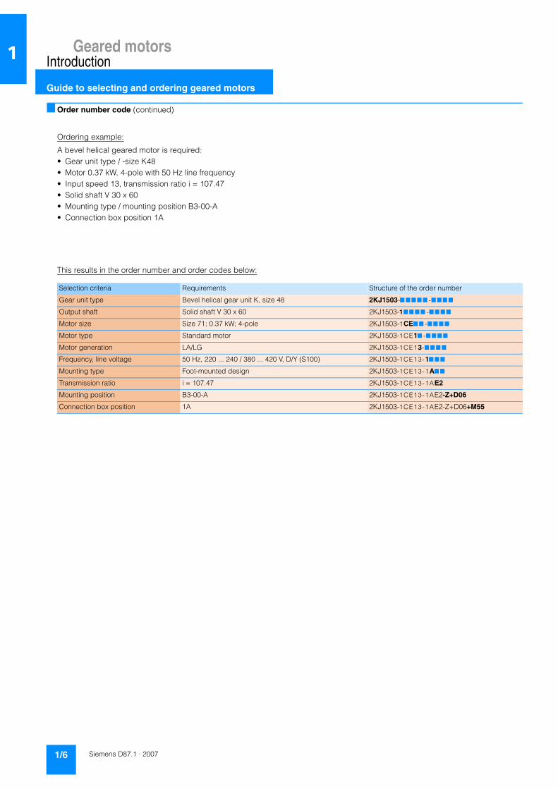
Ordering example:
A bevel helical geared motor is required:• Gear unit type / -size K48• Motor 0.37 kW, 4-pole with 50 Hz line frequency• Input speed 13, transmission ratio i = 107.47• Solid shaft V 30 x 60• Mounting type / mounting position B3-00-A• Connection box position 1A
This results in the order number and order codes below:
Selection criteria Requirements Structure of the order number
Gear unit type Bevel helical gear unit K, size 48 2KJ1503-7 777 7 -777 7
Output shaft Solid shaft V 30 x 60 2KJ1503-177 77 -77 77
Motor size Size 71; 0.37 kW; 4-pole 2KJ1503-1CE7 7 -7 77 7
Motor type Standard motor 2KJ1503-1CE17 -777 7
Motor generation LA/LG 2KJ1503-1CE13-777 7
Frequency, line voltage 50 Hz, 220 ... 240 / 380 ... 420 V, D/Y (S100) 2KJ1503-1CE13-17 77
Mounting type Foot-mounted design 2KJ1503-1CE13-1A7 7
Transmission ratio i = 107.47 2KJ1503-1CE13-1AE2
Mounting position B3-00-A 2KJ1503-1CE13-1AE2-Z+D06
Connection box position 1A 2KJ1503-1CE13-1AE2-Z+D06+M55

Geared motorsIntroduction
Guide to selecting and ordering geared motors
1/7Siemens D87.1 · 2007
1
■ Determining the gear unit type in accordance with the power and input speed
Power PMotor
kW (50 Hz)
Output speed n2 (50 Hz)1/min
TorqueT2
Nm
Gear ratioitot
For further information, see page
Helical geared motors E, D, and Z0.09 3.00 … 6.6 285 … 130.0 208.77 … 133.57 2/10
0.12 0.05 … 302.0 16373 … 3.8 28260.00 … 4.47 2/10 … 2/13
0.18 0.05 … 377.0 24136 … 4.6 24996.00 … 3.58 2/13 … 2/17
0.25 0.08 … 486.0 23171 … 5.1 16361.00 … 3.33 2/17 … 2/20
0.37 0.12 … 383.0 24391 … 9.2 11066.00 … 3.58 2/21 … 2/24
0.55 0.20 … 415.0 23539 … 13.0 7008.00 … 3.31 2/24 … 2/28
0.75 0.27 … 558.0 23419 … 13.0 5107.00 … 2.50 2/28 … 2/32
1.1 0.40 … 890.0 24043 … 12.0 3580.00 … 1.59 2/32 … 2/36
1.5 0.64 … 934.0 24512 … 15.0 2666.00 … 1.52 2/36 … 2/40
2.2 0.84 … 934.0 22829 … 22.0 1682.00 … 1.52 2/40 … 2/44
3 1.10 … 934.0 23331 … 31.0 1255.00 … 1.52 2/44 … 2/49
4 1.60 … 1021.0 21939 … 37.0 896.00 … 1.41 2/49 … 2/52
5.5 2.00 … 1032.0 24909 … 51.0 746.00 … 1.41 2/53 … 2/57
7.5 2.70 … 1032.0 24896 … 69.0 546.00 … 1.41 2/57 … 2/61
9.2 5.00 … 1032.0 17465 … 85.0 289.23 … 1.41 2/61 … 2/64
11 4.40 … 1035.0 24093 … 101.0 243.82 … 1.41 2/65 … 2/68
15 6.00 … 1074.0 23923 … 133.0 243.82 … 1.36 2/68 … 2/71
18.5 7.10 … 1081.0 24799 … 163.0 206.34 … 1.36 2/71 … 2/74
22 9.60 … 1081.0 21885 … 194.0 153.12 … 1.36 2/75 … 2/77
30 12.10 … 1081.0 23713 … 265.0 121.67 … 1.36 2/78 … 2/80
37 14.70 … 1088.0 24104 … 325.0 100.96 … 1.36 2/80 … 2/82
45 18.30 … 1088.0 23453 … 395.0 80.77 … 1.36 2/82 … 2/85
55 21.00 … 905.0 24551 … 580.0 69.41 … 1.64 2/85 … 2/86
75 35.00 … 512.0 20716 … 1399.0 42.95 … 2.90 2/86 … 2/87
90 35.00 … 512.0 24859 … 1678.0 42.95 … 2.90 2/88
110 88.00 … 179.0 11927 … 5871.0 16.86 … 8.30 2/89
132 88.00 … 179.0 14312 … 7046.0 16.86 … 8.30 2/89
160 88.00 … 179.0 17348 … 8540.0 16.86 … 8.30 2/89
200 88.00 … 179.0 21685 … 10675.0 16.86 … 8.30 2/89
Parallel shaft geared motors FZ and FD0.09 2.30 … 4.6 367 … 186.0 280.41 … 191.34 3/8
0.12 0.05 … 121.0 16802 … 9.5 29000.00 … 11.16 3/8 … 3/11
0.18 0.05 … 248.0 24429 … 8.3 25299.00 … 6.53 3/11 … 3/14
0.25 0.09 … 355.0 22462 … 6.7 15519.00 … 3.80 3/14 … 3/17
0.37 0.13 … 73.0 23944 … 49.0 10863.00 … 18.86 3/17 … 3/19
0.55 0.19 … 171.0 24059 … 31.0 7163.00 … 8.06 3/19 … 3/22
0.75 0.28 … 362.0 23016 … 20.0 5021.00 … 3.80 3/22 … 3/25
1.1 0.38 … 372.0 25111 … 28.0 3739.00 … 3.80 3/25 … 3/28
1.5 0.98 … 374.0 21689 … 38.0 2359.00 … 3.80 3/28 … 3/31
2.2 0.98 … 366.0 23887 … 57.0 1760.00 … 3.80 3/31 … 3/34
3 1.10 … 374.0 22960 … 77.0 1236.00 … 3.80 3/35 … 3/38
4 2.40 … 333.0 16239 … 115.0 411.98 … 4.33 3/38 … 3/40
5.5 2.40 … 366.0 22329 … 143.0 403.86 … 3.97 3/40 … 3/43
7.5 3.20 … 366.0 22323 … 195.0 403.86 … 3.97 3/43 … 3/45
9.2 3.60 … 366.0 24387 … 288.0 403.86 … 3.97 3/45 … 3/47
11 4.90 … 306.0 21528 … 343.0 299.20 … 4.77 3/48 … 3/49

Geared motorsIntroduction
Guide to selecting and ordering geared motors
1/8 Siemens D87.1 · 2007
1
Determining the gear unit type in accordance with the power and input speed (continued)
Power PMotor
kW (50 Hz)
Output speed n2 (50 Hz)1/min
TorqueT2
Nm
Gear ratioitot
For further information, see page
Parallel shaft geared motors FZ and FD15 5.9 … 306 24416 … 306 248.85 … 4.77 3/49 … 3/51
18.5 7.6 … 259 23263 … 683 193.56 … 5.68 3/51 … 3/53
22 8.8 … 387 23873 … 543 167.03 … 3.80 3/53 … 3/54
30 11.6 … 387 24766 … 741 127.07 … 3.80 3/54 … 3/56
37 15.7 … 389 22509 … 907 94.28 … 3.80 3/56 … 3/57
45 17.3 … 389 24838 … 1103 85.54 … 3.80 3/57 … 3/58
55 24.0 … 281 22397 … 1868 63.32 … 5.28 3/59
75 31.0 … 281 23373 … 2547 48.46 … 5.28 3/60
90 40.0 … 281 21461 … 3056 37.08 … 5.28 3/60 … 3/61
110 88.0 … 178 11991 … 5900 16.95 … 8.34 3/61
132 88.0 … 178 14389 … 7080 16.95 … 8.34 3/61
160 88.0 … 178 17441 … 8581 16.95 … 8.34 3/61
200 88.0 … 178 21801 … 10727 16.95 … 8.34 3/61
Bevel helical geared motors B and K0.09 3.70 … 7.1 244 … 121.0 179.13 … 124.78 4/9
0.12 0.05 … 180.0 16116 … 6.4 27817.00 … 7.49 4/9 … 4/12
0.18 0.06 … 296.0 23355 … 5.8 24187.00 … 4.56 4/12 … 4/15
0.25 0.08 … 378.0 24007 … 6.3 16951.00 … 3.57 4/15 … 4/18
0.37 0.12 … 93.0 24723 … 38.0 11463.00 … 14.75 4/18 … 4/21
0.55 0.19 … 302.0 24264 … 17.0 7224.00 … 4.56 4/21 … 4/24
0.75 0.26 … 385.0 24777 … 19.0 5405.00 … 3.57 4/24 … 4/28
1.1 0.41 … 396.0 22902 … 26.0 3410.00 … 3.57 4/28 … 4/31
1.5 0.55 … 398.0 23914 … 36.0 2601.00 … 3.57 4/31 … 4/35
2.2 0.92 … 389.0 21051 … 54.0 1551.00 … 3.57 4/35 … 4/38
3 1.10 … 398.0 23889 … 72.0 1286.00 … 3.57 4/38 … 4/41
4 1.50 … 269.0 23702 … 142.0 968.00 … 5.36 4/41 … 4/43
5.5 2.20 … 271.0 22338 … 193.0 669.00 … 5.36 4/44 … 4/46
7.5 2.70 … 271.0 24988 … 264.0 548.00 … 5.36 4/46 … 4/48
9.2 3.40 … 271.0 24013 … 324.0 429.00 … 5.36 4/48 … 4/50
11 4.20 … 264.0 25035 … 399.0 191.34 … 5.54 4/50 … 4/51
15 6.00 … 264.0 24036 … 544.0 191.34 … 5.54 4/51 … 4/53
18.5 7.70 … 207.0 22997 … 853.0 191.34 … 7.10 4/53 … 4/54
22 8.50 … 304.0 24695 … 690.0 172.78 … 4.83 4/54 … 4/55
30 12.20 … 304.0 23419 … 941.0 120.16 … 4.83 4/56 … 4/57
37 15.50 … 306.0 22796 … 1153.0 95.48 … 1153.00 4/57 … 4/58
45 18.70 … 306.0 23006 … 1402.0 79.23 … 4.83 4/58 … 4/59
55 23.00 … 307.0 22418 … 1708.0 63.38 … 4.83 4/59 … 4/60
75 35.00 … 225.0 20465 … 3188.0 42.43 … 6.61 4/60 … 4/61
90 35.00 … 225.0 24558 … 3826.0 42.43 … 6.61 4/61
110 76.00 … 123.0 13837 … 8560.0 19.56 … 12.10 4/61
132 76.00 … 123.0 16604 … 10272.0 19.56 … 12.10 4/61
160 76.00 … 123.0 20126 … 12450.0 19.56 … 12.10 4/61
200 98.00 … 123.0 19589 … 15563.0 15.23 … 12.10 4/61

Geared motorsIntroduction
Guide to selecting and ordering geared motors
1/9Siemens D87.1 · 2007
1
Helical worm geared motors C0.09 2.00 … 4 241 … 126 320.67 … 223.36 5/8
0.12 0.20 … 53 1980 … 20 6722.00 … 25.28 5/8… 5/10
0.18 0.36 … 53 1911 … 30 3719.00 … 25.28 5/10 … 5/11
0.25 0.60 … 53 1782 … 41 2256.00 … 25.28 5/11 … 5/13
0.37 0.91 … 54 1918 … 60 1510.00 … 25.28 5/13 … 5/14
0.55 1.70 … 54 1870 … 68 440.70 … 20.31 5/14 … 5/16
0.75 2.3 0 … 144 1987 … 44 440.70 … 9.67 5/16 … 5/18
1.1 4.00 … 146 1851 … 63 354.55 … 9.67 5/18 … 5/19
1.5 6.2 0 … 147 1671 … 86 228.00 … 9.67 5/20 … 5/21
2.2 11.30 … 147 1369 … 126 126.18 … 9.67 5/21 … 5/23
3 14.50 … 147 1686 … 172 98.17 … 9.67 5/23 … 5/24
4 22.00 … 149 1482 … 227 65.32 … 9.67 5/24 … 5/25
5.5 35.00 … 130 1293 … 364 41.85 … 11.15 5/25 … 5/26
7.5 62.00 … 130 992 … 497 23.56 … 11.15 5/26
9.2 82.00 … 130 966 … 609 17.67 … 11.15 5/26
11 109.00 … 131 872 … 726 13.39 … 11.15 5/26
Worm gear unit SC0.09 6.3 … 30 74 … 21 100 … 30 6/5
0.12 6.4 … 68 96 … 14 100 … 20 6/5
0.18 8.4 … 135 111 … 11 100 … 10 6/5 … 6/6
0.25 8.3 … 193 155 … 11 100 … 7 6/6
0.37 11.5 … 196 187 … 16 100 … 7 6/7
0.55 11.4 … 61 282 … 71 80 … 15 6/7
0.75 23.0 … 199 203 … 33 60 … 7 6/7 … 6/8
1.1 47.0 … 202 165 … 48 30 … 7 6/8
1.5 71.0 … 203 167 … 65 20 … 7 6/8
Determining the gear unit type in accordance with the power and input speed (continued)
Power PMotor
kW (50 Hz)
Output speed n2 (50 Hz)1/min
TorqueT2
Nm
Gear ratioitot
For further information, see page
Geared motorsIntroduction
Guide to selecting and ordering geared motors
1/10 Siemens D87.1 · 2007
1
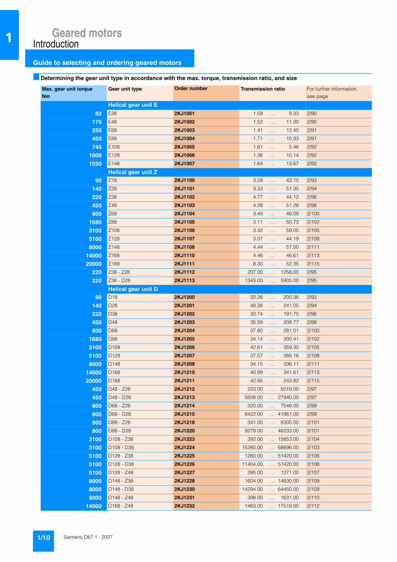
■ Determining the gear unit type in accordance with the max. torque, transmission ratio, and size
Max. gear unit torqueNm
Gear unit type Order number Transmission ratio For further information,see page
Helical gear unit E
82 E38 2KJ1001 1.59 … 9.33 2/90
170 E48 2KJ1002 1.52 … 11.30 2/90
250 E68 2KJ1003 1.41 … 12.40 2/91
450 E88 2KJ1004 1.71 … 10.33 2/91
745 E108 2KJ1005 1.81 … 5.46 2/92
1000 E128 2KJ1006 1.36 … 10.14 2/92
1550 E148 2KJ1007 1.64 … 13.67 2/92
Helical gear unit Z90 Z18 2KJ1100 3.58 … 43.15 2/93
140 Z28 2KJ1101 3.33 … 51.35 2/94
220 Z38 2KJ1102 4.77 … 44.12 2/96
450 Z48 2KJ1103 4.28 … 51.28 2/98
800 Z68 2KJ1104 3.49 … 48.09 2/100
1680 Z88 2KJ1105 3.11 … 50.73 2/102
3100 Z108 2KJ1106 3.42 … 59.05 2/105
5100 Z128 2KJ1107 3.07 … 44.19 2/108
8000 Z148 2KJ1108 4.44 … 57.50 2/111
14000 Z168 2KJ1110 4.46 … 46.61 2/113
20000 Z188 2KJ1111 8.30 … 52.35 2/115
220 Z38 - Z28 2KJ1112 207.00 … 1258.00 2/95
220 Z38 - D28 2KJ1113 1343.00 … 5905.00 2/95
Helical gear unit D90 D18 2KJ1200 32.26 … 200.36 2/93
140 D28 2KJ1201 48.38 … 241.05 2/94
220 D38 2KJ1202 30.74 … 191.75 2/96
450 D48 2KJ1203 35.59 … 208.77 2/98
800 D68 2KJ1204 37.80 … 281.01 2/100
1680 D88 2KJ1205 34.14 … 300.41 2/102
3100 D108 2KJ1206 42.61 … 359.30 2/105
5100 D128 2KJ1207 37.57 … 268.16 2/108
8000 D148 2KJ1208 34.15 … 336.11 2/111
14000 D168 2KJ1210 40.99 … 341.61 2/113
20000 D188 2KJ1211 42.95 … 243.82 2/115
450 D48 - Z28 2KJ1212 223.00 … 5019.00 2/97
450 D48 - D28 2KJ1213 5608.00 … 27940.00 2/97
800 D68 - Z28 2KJ1214 320.00 … 7548.00 2/99
800 D68 - D28 2KJ1215 8422.00 … 41961.00 2/99
800 D88 - Z28 2KJ1218 341.00 … 8305.00 2/101
800 D88 - D28 2KJ1220 9279.00 … 46233.00 2/101
3100 D108 - Z38 2KJ1223 392.00 … 15853.00 2/104
3100 D108 - D38 2KJ1224 15280.00 … 68896.00 2/103
5100 D128 - Z38 2KJ1225 1280.00 … 51420.00 2/106
5100 D128 - D38 2KJ1226 11404.00 … 51420.00 2/106
5100 D128 - Z48 2KJ1227 285.00 … 1271.00 2/107
8000 D148 - Z38 2KJ1228 1604.00 … 14830.00 2/109
8000 D148 - D38 2KJ1230 14294.00 … 64450.00 2/109
8000 D148 - Z48 2KJ1231 398.00 … 1631.00 2/110
14000 D168 - Z48 2KJ1232 1463.00 … 17519.00 2/112

Geared motorsIntroduction
Guide to selecting and ordering geared motors
1/11Siemens D87.1 · 2007
1
Determining the gear unit type in accordance with the max. torque, transmission ratio, and size (continued)
Max. gear unit torqueNm
Gear unit type Order number Transmission ratio For further information,see page
Helical gear unit D14000 D168 - D48 2KJ1233 17080 … 71317 2/112
14000 D168 - Z68 2KJ1234 376 … 1226 2/112
20000 D188 - Z48 2KJ1235 1044 … 12504 2/114
20000 D188 - D48 2KJ1236 12191 … 50901 2/114
20000 D188 - Z68 2KJ1237 322 … 896 2/114
Parallel shaft gear unit FZ150 FZ28 2KJ1300 56.20 … 280.00 3/62
290 FZ38B 2KJ1301 4.52 … 56.72 3/64
540 FZ48B 2KJ1302 4.33 … 60.71 3/66
1000 FZ68B 2KJ1303 3.97 … 61.17 3/68
1900 FZ88B 2KJ1304 4.77 … 64.58 3/70
3400 FZ108B 2KJ1305 5.68 … 64.21 3/72
6100 FZ128B 2KJ1306 3.80 … 56.42 3/74
9000 FZ148B 2KJ1307 5.39 … 68.23 3/76
14000 FZ168B 2KJ1308 5.28 … 53.48 3/78
20000 FZ188B 2KJ1310 8.34 … 52.63 3/80
290 FZ38B - Z28 2KJ1313 303.00 … 1617.00 3/63
290 FZ38B - D28 2KJ1314 1726.00 … 7591.00 3/63
Parallel shaft gear unit FD150 FD28 2KJ1400 3.80 … 59.65 3/62
290 FD38B 2KJ1401 56.28 … 280.41 3/64
540 FD48B 2KJ1402 43.09 … 268.80 3/66
1000 FD68B 2KJ1403 50.48 … 296.18 3/68
1900 FD88B 2KJ1404 54.47 … 404.92 3/70
3400 FD108B 2KJ1405 48.24 … 424.49 3/72
6100 FD128B 2KJ1406 53.13 … 447.96 3/74
9000 FD148B 2KJ1407 62.93 … 449.21 3/76
14000 FD168B 2KJ1408 41.85 … 369.26 3/78
20000 FD188B 2KJ1410 48.46 … 403.86 3/80
540 FD48B - Z28 2KJ1413 299.00 … 4197.00 3/65
540 FD48B - D28 2KJ1414 4480.00 … 19701.00 3/65
1000 FD68B - Z28 2KJ1417 317.00 … 4454.00 3/67
1000 FD68B - D28 2KJ1418 4755.00 … 39638.00 3/67
1900 FD88B - Z28 2KJ1422 461.00 … 6000.00 3/69
1900 FD88B - D28 2KJ1423 6703.00 … 54705.00 3/69
3400 FD108B - Z38 2KJ1426 466.00 … 15230.00 3/71
3400 FD108B - D38 2KJ1427 16603.00 … 66190.00 3/71
6100 FD128B - Z38 2KJ1428 1970.00 … 15663.00 3/73
6100 FD128B - D38 2KJ1430 17075.00 … 68070.00 3/73
6100 FD128B - Z48 2KJ1431 439.00 … 1504.00 3/73
9000 FD148B - Z38 2KJ1432 1757.00 … 16239.00 3/75
9000 FD148B - D38 2KJ1433 17704.00 … 70576.00 3/75
9000 FD148B - Z48 2KJ1434 477.00 … 1634.00 3/75
14000 FD168B - Z48 2KJ1435 1337.00 … 16007.00 3/77
14000 FD168B - D48 2KJ1436 17454.00 … 65160.00 3/77
14000 FD168B - Z68 2KJ1437 398.00 … 1298.00 3/77
20000 FD188B - Z48 2KJ1438 1465.00 … 17537.00 3/79
20000 FD188B - D48 2KJ1440 19122.00 … 71388.00 3/79
20000 FD188B - Z68 2KJ1441 444.00 … 1449.00 3/79

Geared motorsIntroduction
Guide to selecting and ordering geared motors
1/12 Siemens D87.1 · 2007
1
Bevel helical gear units B and K130 B28 2KJ1500 3.57 … 57.53 4/62
250 B38 2KJ1501 3.84 … 65.69 4/63
250 K38 2KJ1502 5.65 … 179.13 4/65
450 K48 2KJ1503 7.22 … 169.53 4/68
820 K68 2KJ1504 5.36 … 243.72 4/70
1650 K88 2KJ1505 5.54 … 302.68 4/72
3000 K108 2KJ1506 7.68 … 307.24 4/74
4700 K128 2KJ1507 7.10 … 295.38 4/77
8000 K148 2KJ1508 4.83 … 306.08 4/79
13500 K168 2KJ1510 6.61 … 287.95 4/81
20000 K188 2KJ1511 12.10 … 191.34 4/83
250 K38 - Z28 2KJ1514 181.00 … 2797.00 4/64
250 K38 - D28 2KJ1515 2986.00 … 13129.00 4/64
450 K48 - Z28 2KJ1516 181.00 … 2798.00 4/67
450 K48 - D28 2KJ1517 2987.00 … 13135.00 4/66
820 K68 - Z28 2KJ1518 277.00 … 4282.00 4/69
820 K68 - D28 2KJ1520 4572.00 … 20103.00 4/69
1650 K88 - Z28 2KJ1523 344.00 … 5309.00 4/71
1650 K88 - D28 2KJ1524 5667.00 … 24920.00 4/71
3000 K108 - Z38 2KJ1527 1466.00 … 13556.00 4/73
3000 K108 - D38 2KJ1528 13066.00 … 58914.00 4/73
3000 K108 - Z48 2KJ1530 301.00 … 1343.00 4/74
4700 K128 - Z38 2KJ1531 1410.00 … 13032.00 4/75
4700 K128 - D38 2KJ1532 12562.00 … 56640.00 4/75
4700 K128 - Z48 2KJ1533 313.00 … 1400.00 4/76
8000 K148 - Z38 2KJ1534 1466.00 … 13505.00 4/78
8000 K148 - D38 2KJ1535 13017.00 … 58692.00 4/78
8000 K148 - Z68 2KJ1536 296.00 … 1392.00 4/78
13500 K168 - Z48 2KJ1537 1233.00 … 14767.00 4/80
13500 K168 - D48 2KJ1538 14397.00 … 60115.00 4/80
13500 K168 - Z68 2KJ1540 317.00 … 1033.00 4/80
20000 K188 - Z68 2KJ1541 669.00 … 9201.00 4/82
20000 K188 - D68 2KJ1542 8689.00 … 53767.00 4/82
20000 K188 - Z88 2KJ1543 225.00 … 669.00 4/83
Determining the gear unit type in accordance with the max. torque, transmission ratio, and size (continued)
Max. gear unit torqueNm
Gear unit type Order number Transmission ratio For further information,see page

Geared motorsIntroduction
Guide to selecting and ordering geared motors
1/13Siemens D87.1 · 2007
1
Helical worm gear unit C118 C28 2KJ1600 25.28 … 372.00 5/27 … 5/28
243 C38 2KJ1601 9.67 … 320.67 5/30 … 5/32
387 C48 2KJ1602 9.67 … 320.67 5/34 … 5/36
687 C68 2KJ1603 11.67 … 364.00 5/38 … 5/40
1590 C88 2KJ1604 11.15 … 440.70 5/42 … 5/44
225 C38 - Z28 2KJ1605 324.00 … 4222.00 5/29
222 C38 - D28 2KJ1606 4717.00 … 23503.00 5/29
369 C48 - Z28 2KJ1607 324.00 … 4222.00 5/33
364 C48 - D28 2KJ1608 4717.00 … 23503.00 5/33
680 C68 - Z28 2KJ1610 398.00 … 5066.00 5/37
675 C68 - D28 2KJ1611 5661.00 … 28203.00 5/37
1590 C88 - Z28 2KJ1614 6722.00 … 33491.00 5/41
1590 C88 - D28 2KJ1615 462.00 … 6016.00 5/41
Worm gear unit SC43 SC36 2KJ1700 7 … 60 6/9
80 SC50 2KJ1701 7 … 100 6/9
166 SC63 2KJ1702 7 … 100 6/9
Determining the gear unit type in accordance with the max. torque, transmission ratio, and size (continued)
Max. gear unit torqueNm
Gear unit type Order number Transmission ratio For further information,see page

Geared motorsIntroduction
Guide to selecting and ordering geared motors
1/14 Siemens D87.1 · 2007
1
■ Overview of "special versions"
Order code Special version For further information,see page
Input unitsA00 Input unit A with free shaft extension 7/3, 7/13
A03 Input unit K2 with coupling for connecting IEC motors 7/3, 7/7
A04 Input unit K4 for connecting IEC motors 7/3, 7/9
A07 Input unit KQ for attaching servo motors (with parallel key) 7/3, 7/11
A08 Input unit KQS for attaching servo motors (with plain shaft) 7/3, 7/11
A09 Input unit P with free shaft extension and piggy back 7/3, 7/13
A10 Input unit PS with free shaft extension, piggy back, and protective belt cover 7/3
N61 Size index .2 for KQ/KQS coupling lantern for servo motors 7/3
N62 Size index .3 for KQ/KQS coupling lantern for servo motors 7/3
N63 Size index .4 for KQ/KQS coupling lantern for servo motors 7/3
Backstop in the input unitA15 Backstop X 7/16
Coupling types and input unit optionsA16 Flexible coupling 7/3
A17 Slip clutch 7/16
A18 Proximity switch 7/16
A19 Speed monitor 7/16
Piggy back positionA22 3h 7/39 … 7/44
A23 9h 7/39 … 7/44
A24 12h 7/39 … 7/44
Brake typeB00 to B62 Brake types according to size and braking torque 8/24 … 8/25
Brake designC01 Enclosed brake (G) 8/33
C02 Manual release (H) 8/31
C03 Manual release, lockable (HA) 8/31
C04 Microswitch for monitoring release for brake 8/30
C06 Reduced-noise rotor / hub connection 8/29
C09 Basic anti-corrosion protection 8/33
C10 Increased anti-corrosion protection 8/33
C11 Enclosed brake (G) with condensation drainage hole 8/33
Manual brake release lever positionC26 1 8/31
C27 2 8/31
C28 3 8/31
C29 4 8/31
Brake control voltageC46 + C30 190 … 240 V AC 8/26
C47 + C30 380 … 440 V AC 8/26
C48 + C33 95 … 120 V AC 8/26
C52 92 … 110 V DC 8/26
C53 170 … 200 V DC 8/26
C61 + C33 190 … 220 V AC 8/26
C62 + C33 205 … 240 V AC 8/26
C63 + C31 410 … 480 V AC 8/26
C64 184 … 218 V DC 8/26

Geared motorsIntroduction
Guide to selecting and ordering geared motors
1/15Siemens D87.1 · 2007
1
Overview of "special versions" (continued)
Order code Special version For further information,see page
Brake control voltage (continued)C65 + C33 230 V AC 8/26
C66 24 V DC ±10 % 8/26
C67 + C30 400 V AC 8/26
C68 + C30 460 V AC 8/26
C69 + C33 24 ... 29 V AC 8/26
C70 + C30 48 ... 58 V AC 8/26
Mounting types / mounting positionsD00 to E17 Geared motor mounting types and mounting positions 2/119-2/128, 3/87-3/88, 4/90-4/92,
5/49-5/50, 6/15
Flange-mounted designs (worm gear unit)G06 Short flange 6/14
G07 Long flange 6/14
Torque arm figureG09 Figure 1 4/85, 5/46
G10 Figure 2 4/85, 5/46
Bearing arrangementG20 Radial reinforced output bearings 2/132, 3/92, 4/97, 5/54
SealingG23 Dual sealing 2/131, 3/91, 4/96, 5/53
G24 Combination of seals 2/131, 3/91, 4/96, 5/53
G25 Viton sealing 2/131, 3/91, 4/96, 5/53
Oil level controlG34 Oil sight glass 2/130, 3/90, 4/94, 5/52
G37 Electrical oil level monitoring system: capacitive sensor 2/130, 3/90, 4/94, 5/52
G39 Electrical oil level monitoring system: isolation amplifier 24 V 2/130, 3/90, 4/94, 5/52
Gear unit ventilationG44 Breather filter 2/130, 3/90, 4/95, 5/52
G45 Pressure breather valve 2/130, 3/90, 4/95, 5/52
Oil drainG53 Magnetic oil drain plug 2/131, 3/91, 4/96, 5/53
G54 Straight oil drain valve 2/131, 3/91, 4/96, 5/53
Non-drive-end coverG60 Steel protective cover 3/92, 4/97, 5/54
G61 Steel protective cover, sealed 3/92, 4/97, 5/54
G62 Cast iron protective cover 3/92, 4/97, 5/54
G63 Cast iron protective cover, sealed 3/92, 4/97, 5/54
Backstop for bevel helical gear unitG72 Backstop (gear unit) 4/98
Options for gear unit output shaftsG73 Second output shaft extension 4/98, 5/54, 6/16
Dry-well options for mixer and agitator drivesG89 Dry-well design with sight glass 2/132, 3/93, 4/99
G90 Dry-well design with capacitive sensor 2/132, 3/93, 4/99

Geared motorsIntroduction
Guide to selecting and ordering geared motors
1/16 Siemens D87.1 · 2007
1
Flange diameterH01 to H06 Flange diameter 2/118, 3/86, 4/89, 5/48, 6/14
Foot position for worm gear unitsH32 6h 6/12
H33 9h 6/12
H44 12h 6/12
Degree of protectionK01 IP55 8/6
K03 IP65 8/6
LubricantsK06 Mineral oil CLP ISO VG 220 1/45, 2/130, 3/90, 4/94
K07 Synthetic oil ISO CLP PG VG 220 1/45, 2/130, 3/90, 4/94
K08 Synthetic oil ISO CLP PG VG 460 1/45, 2/130, 3/90, 4/94, 5/52
K10 Oil for use in the food industry in acc. with USDA-H1 CLP ISO PAO VG 460 1/45, 2/130, 3/90, 4/94, 5/52
K11 Biologically degradable oil CLP ISO E VG 220 1/45, 2/130, 3/90, 4/94
K12 Synthetic oil CLP ISO PAO VG 220 for low temperature usage 1/45, 2/130, 3/90, 4/94, 5/52
K13 Synthetic oil CLP ISO PAO VG 68 for lowest temperature usage 1/45, 2/130, 3/90, 4/94
Long-term preservationK17 Long-term preservation up to 36 months 1/45
Direction of rotation of the output shaft (required with backstop)K18 Clockwise 1/42, 4/98
K19 Counterclockwise 1/42, 4/98
Rating plate and additional platesK41 Additional rating plate 1/47
Coats of paintL00 Unpainted 1/46
L01 Primed 1/46
L02 Acrylic coating 1/46
L03 2-component PUR 1/46
L04 2-component epoxy 1/46
RAL colorsL50 5015 sky blue 1/46
L51 7011 iron gray 1/46
L52 2004 pure orange 1/46
L53 7031 blue gray (standard with 2-component PUR) 1/46
L54 7035 light gray (standard with 2-component epoxy) 1/46
Other colors can be selected by entering order code Y80 and plain text. 1/46
Insulating material classM09 Special insulation for inverter-fed operation up to 690 V + 5 % 8/76
Thermal motor protectionM10 PTC thermistor for shutdown 8/17
M11 PTC thermistor for warning and shutdown 8/17
M12 Winding thermostat for shutdown (WT) 8/17
M13 Winding thermostat for warning and shutdown for sizes 71 to 200 (WT) 8/17
M16 Temperature sensor KTY84-130 8/17
Overview of "special versions" (continued)
Order code Special version For further information,see page

Geared motorsIntroduction
Guide to selecting and ordering geared motors
1/17Siemens D87.1 · 2007
1
FanM21 Metal fan 8/7
M22 High inertia fan 8/7
M23 Separate fan 8/7
Forced ventilation supply voltageM34 Separate fan standard voltage 8/7
Anti-condensation heatingM40 115 V supply voltage 8/21
M41 230 V supply voltage 8/21
Terminal box positionM55 to M70 Position of the terminal box and cable entry 8/9
ECOFAST motor plugsN04 ECOFAST motor plug HAN10E 8/14
N05 ECOFAST motor plug HAN10E with ECOFAST counterplug HAN10B 8/14
N06 ECOFAST motor plug HAN10E, EMC design 8/14
N07 ECOFAST motor plug HAN10E with ECOFAST counterplug HAN10B, EMC design 8/14
Worm gear unit SC for attaching IEC motorsN19 Flange B5 on the input side 6/16
N21 Flange B14 on the input side 6/16
Protection coverN22 Protection cover 8/6
Backstop on motorN23 Motor backstop 8/46
Second shaft extension on motorN39 Second shaft extension 8/46
Designs in accordance with standards and specificationsN30 Design in accordance with GOST 1/38, 8/3
N65 Design in accordance with NEMA (electrical) 1/37, 8/3
N67 Design in accordance with CCC 1/38, 8/3
Pole number of the motorP00 2-pole 8/50
P01 6-pole 8/52 - 8/53, 8/60 - 8/61, 8/72 - 8/73
P02 8-pole 8/62 - 8/63, 8/68 - 8/69, 8/74 - 8/75
P08 8/4-pole 8/56 - 8/57
Overview of "special versions" (continued)
Order code Special version For further information,see page

Geared motorsIntroduction
Guide to selecting and ordering geared motors
1/18 Siemens D87.1 · 2007
1
Rotary pulse encodersQ50 Rotary pulse encoder 1XP8 012-20 (IN 1024 TTL with flange socket) 8/39
Q51 Rotary pulse encoder 1XP8 012-21 (IN 2048 TTL with flange socket) 8/39
Q52 Rotary pulse encoder 1XP8 012-22 (IN 512 TTL with flange socket) 8/39
Q53 Rotary pulse encoder 1XP8 012-10 (IN 1024 HTL with flange socket) 8/39
Q54 Rotary pulse encoder 1XP8 012-11 (IN 2048 HTL with flange socket) 8/39
Q55 Rotary pulse encoder 1XP8 012-12 (IN 512 HTL with flange socket) 8/39
Q56 Rotary pulse encoder 1XP8 022-20 (IN 1024 TTL with cable terminal box) 8/40
Q57 Rotary pulse encoder 1XP8 022-21 (IN 2048 TTL with cable terminal box) 8/40
Q58 Rotary pulse encoder 1XP8 022-22 (IN 512 TTL with cable terminal box) 8/40
Q59 Rotary pulse encoder 1XP8 022-10 (IN 1024 HTL with cable terminal box) 8/40
Q60 Rotary pulse encoder 1XP8 022-11 (IN 2048 HTL with cable terminal box) 8/40
Q61 Rotary pulse encoder 1XP8 022-12 (IN 512 HTL with cable terminal box) 8/40
Q62 Connector 8/44
Q63 Cable with wire end ferrules, 2 m 8/44
Q64 Cable with wire end ferrules, 8 m 8/44
Q65 Cable with wire end ferrules, 15 m 8/44
Q66 Cable with coupling socket, 2 m 8/45
Q67 Cable with coupling socket, 8 m 8/45
Q68 Cable with coupling socket, 15 m 8/45
Q69 Cable with connector and wire end ferrules, 2 m 8/44
Q70 Cable with connector and wire end ferrules, 8 m 8/44
Q71 Cable with connector and wire end ferrules, 15 m 8/44
Q72 Cable with coupling socket, 2 m 8/45
Q73 Cable with coupling socket, 8 m 8/45
Q74 Cable with coupling socket, 15 m 8/45
Q80 Absolute encoder 1XP8014-20 (IA SSI protocol with flange socket) 8/43
Q81 Absolute encoder 1XP8024-20 (IA SSI protocol cable with coupling socket) 8/43
Q82 Absolute encoder 1XP8014-10 (IA EnDat protocol with flange socket) 8/43
Q83 Absolute encoder 1XP8024-10 (IA EnDat protocol cable with coupling socket) 8/43
Q85 Resolver 1XP8013-10 (IR with flange socket) 8/42
Q86 Resolver 1XP8023-10 (IR cable with coupling socket) 8/42
Overview of "special versions" (continued)
Order code Special version For further information,see page
Geared motorsIntroduction
Configuring guide
1/19Siemens D87.1 · 2007
1
■ Determining the drive data
Data relating to the machine to be driven (machine type, mass, input speed, speed range, etc.) is required in order to size the machine correctly. This data is then used to determine the re-quired power, torque, and input speed of the geared motor. The correct drive can be selected based on its calculated power and speed.
Data required for selection
The following data is required in order to select the correct gear unit:
1. Type of driven machine
2. Daily operating time [h]
3. Required input power [kW] or torque [Nm]
4. Required input speed n2 of the geared motor [rpm] or gear ratio i
5. Operating voltage [V] and frequency [Hz]
6. Operating mode, number of starts, inverter-fed operation, type of startup
7. Mass moment of inertia JLoad [kgm2] of the driving machine reduced to the motor shaft
8. Type of power transmission on gear unit shafts (direct, coupling, belt, chain, gear wheel)
9. Radial force Fr [N] at the input shaft and direction of force with distance from the shaft shoulder to the point of application and axial force Fax [N] with direction of force
10. Ambient temperature [°C]
11. Degree of protection
12. Mounting position
13. Required braking torque [Nm]
14. Any regulations (CSA, VIK, etc.)
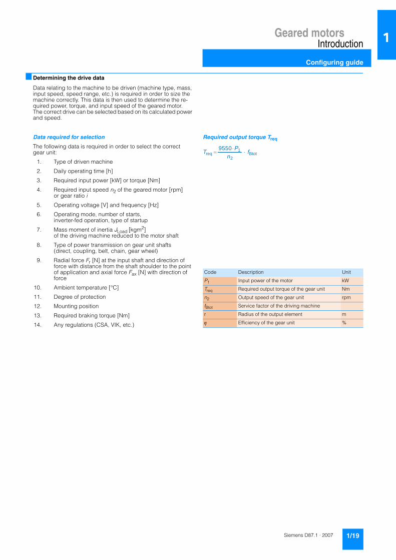
Required output torque Treq
Code Description Unit
P1 Input power of the motor kW
Treq Required output torque of the gear unit Nm
n2 Output speed of the gear unit rpm
fBtot Service factor of the driving machine
r Radius of the output element m
η Efficiency of the gear unit %
fBtotnPT ⋅⋅
=2
1req
9550

Geared motorsIntroduction
Configuring guide
1/20 Siemens D87.1 · 2007
1
■ Efficiency of the geared motor
The efficiency of the gear unit is determined by the gear teeth, rolling-contact bearing friction, and the shaft seals, among other things. The starting efficiency also has to be taken into account, particularly as regards helical worm and worm gear units. Efficiency may be impaired at high input speeds and high trans-mission ratios, if a relatively large amount of oil is used (depending on mounting position), and during cold operation in low temperature ranges.
Helical, bevel helical, and parallel shaft gear units
MOTOX helical, parallel shaft, and bevel helical gear units are extremely efficient. As a rule, efficiencies of 98 % (1-stage), 96 % (2-stage), and 94 % (3-stage) can be assumed.
Helical worm and worm gear units
The gear teeth of the worm gear units lead to high sliding friction losses at high transmission ratios. Therefore, these gear units can be less efficient than other types. The efficiencies of the he-lical worm and worm gear units primarily depend on the trans-mission ratio in question. With helical worm gear units, some of the transmission ratio is realized by the helical gear stage. In this way, higher degrees of efficiency can be achieved. For further information see the selection data in the chapter deal-ing with helical worm gear units.
Self-locking with worm gear units
In respect of restoring torques on worm gear units, the efficiency is considerably reduced in comparison to standard efficiency. The restoring efficiency can be calculated as follows: η ' = 2 - 1/η . At a standard efficiency of η ≤ 0.5, worm gear units are usually self-locking, which is determined by the particular lead angle of the worm gear teeth.Self-locking only occurs with certain combinations of MOTOX gear units and is not always of benefit, as the associated loss of efficiency is then relatively high, which in turn requires increased motor power.
A worm gear unit is "self-locking while stationary" (static self-locking), if it is not possible to start from stationary when the worm wheel is driving. A worm gear unit is "self-braking while running" (dynamic self-locking), if it is not possible to continue running when the worm wheel is driving while the gear unit is running - that is, if the run-ning gear unit comes to a stop while the worm wheel is driving.
Shocks can neutralize self-locking. A self-locking gear unit is, therefore, no substitute for a brake or backstop. If you want to use the self-locking braking effect for a technical purpose, please contact us.
Run-in phase for helical worm and worm gear units
The tooth flanks on new helical worm and worm gear units will not yet be fully smoothed, meaning that the friction angle will be greater and efficiency lower during initial operation. The higher the transmission ratio, the more pronounced the effect.
The run-in procedure should take approximately 24 hours of op-eration at full load. In most cases, the catalog values will then be reached.
Losses of splashing
With certain gear unit mounting positions, the first stage can become completely immersed in the gear lubricant. In the case of large gear units with a high input speed, particularly with ver-tical mounting positions, this may lead to increased losses of splashing, which must not be ignored. Please contact us if you want to use such gear units. If at all possible, you should choose horizontal mounting positions in order to keep losses of splash-ing to a minimum.

Geared motorsIntroduction
Configuring guide
1/21Siemens D87.1 · 2007
1
■ Determining the required service factor
The operating conditions are crucial in determining the service factor and for selecting the geared motor. These conditions are taken into account with service factor fB.
The gear unit size or rated gear torque and the resulting service factor are not standardized and depend on the manufacturer.
In standard operation, i.e. with a uniform load provided by the driving machine, small masses to be accelerated, and a low number of starts, the service factor of fB = 1 can be selected.
For different operating conditions see the tables found under "Service factor". If the motor power and the gear unit output speed are known, a gear unit type is selected from the types page with a service factor that meets the following condition:
For drives operating under special conditions, e.g. frequent re-versing, short-time or intermittent duty, abnormal temperature ratios, reversal braking, extreme or rotating transverse forces on the gear output shaft, etc. please contact us for advice on how to design the drive configuration.
The operating conditions can vary greatly. To determine the service factor, empirical values can be derived from the configuration of other similar applications. The driving machines can be assigned to three load groups according to their shock load. These groups can be assessed by means of their mass acceleration factor (MAF).
In the case of high mass acceleration factors (MAF >10), a large amount of play in the transmission elements, or high transverse forces, unexpected additional loads may arise. Please contact us in such an event.
The mass acceleration factor MAF is calculated as follows:
All external mass moments of inertia are mass moments of iner-tia of the driving machine and the gear unit, which are to be re-duced to the motor speed. In most cases the mass moment of inertia of the gear unit has no effect and can be ignored. The calculation is done using the following formula:
fBtot ≤ fB
Code Description Unit
fBtot Service factor of the driving machine –
fB Service factor of the geared motor –
MAF Mass acceleration factor –
JLoad All external mass moments of inertia (based on the motor shaft)
kgm²
JM Mass moment of inertia of the motor kgm²
JB Mass moment of inertia of the brake kgm²
Jadd Additional moment of inertia (e.g. centrifugal mass or high inertia fan)
kgm²
J2 Mass moment of inertia based on the output speed of the gear unit
kgm²
n1 Input speed of the motor rpm
n2 Output speed of the gear unit rpm
i Gear ratio –
DC Duty cycle %
)( addBM
oadLJJJ
JMAF++
=
22
2
1
22Load
iJ
nnJJ =⎟⎟
⎠
⎞⎜⎜⎝
⎛⋅=

Geared motorsIntroduction
Configuring guide
1/22 Siemens D87.1 · 2007
1
■ Required service factor
Service factor for helical, parallel shaft, and bevel helical gear units
The service factor of the driving machine fBtot is determined from the tables by taking the load classification, number of starts, and duration of service per day into account. Contact our drive experts to check drive sizing in the case of high shock loads and, for example, high motor and braking torques that are greater than 2.5x the rated motor torque.
Load classification for driving machines
Service factors fB1:
* The number of starts is calculated from the sum of times it is switched on, braking operations, and changeovers.
Service factors for helical worm and worm gear units:
With worm gear units, two additional service factors are used, which take the duty cycle and ambient temperature into ac-count. These additional factors can be determined from the graph opposite.
In the standard design the gear units can operate at an ambient temperature of –20 °C to +40 °C.
In the case of a service factor fB3 < 1 for temperatures below 20 °C please contact us.
Service factor fB2 for short-time duty:
fBtot = fB1
Shock load Driving machine
ILight shock loads
Mass acceleration factor ≤ 0.3:Electric generators, belt conveyors, apron conveyors, screw conveyors, lightweight elevators, electric hoists, machine tool feed drives, turbo blowers, centrifugal compressors, mixers and agitators for uniform densities.
IIModerate shock loads
Mass acceleration factor ≤ 3:Machine tool main drives, heavyweight eleva-tors, turning tools, cranes, shaft ventilators, mixers and agitators for non-uniform densi-ties, piston pumps with multiple cylinders, metering pumps.
IIIHeavy shock loads
Mass acceleration factor ≤ 10:Punching presses, shears, rubber kneaders, machinery used in rolling mills and the iron and steel industry, mechanical shovels, heavyweight centrifuges, heavyweight meter-ing pumps, rotary drilling rigs, briquetting presses, pug mills.
Daily operating duration
4 hours 8 hours 16 hours 24 hours
Starts* / h < 10 10 … 200 > 200 < 10 10 … 200 > 200 < 10 10 … 200 > 200 < 10 10 … 200 > 200
Shock load I 0.8 0.9 1.0 0.9 1.0 1.1 1.0 1.1 1.2 1.2 1.3 1.5
II 1.0 1.1 1.3 1.1 1.2 1.3 1.2 1.4 1.5 1.4 1.5 1.6
III 1.3 1.4 1.5 1.4 1.5 1.6 1.5 1.6 1.7 1.6 1.7 1.8
fBtot = fB1· fB2 · fB3
0 10 20 30 40 50 60 70 80 90 100
fB2
1.0
0.9
0.8
0.7
0.6
0.5
G_M
015_
EN
_000
32
DC [%]
10060
Loading time in min/h ⋅=DC

Geared motorsIntroduction
Configuring guide
1/23Siemens D87.1 · 2007
1
■ Required service factor (continued)
Example worm gear unit:
Mass acceleration factor 2.5 (shock load II), runtime 15 hours per day (read off at 16 hours), and 70 starts/h gives a service factor of fB1 = 1.4 for service factor fB1 according to the table.
A load duration of 30 minutes per hour gives a duty cycle (DC) of 50 %. According to the diagram, this results in a service factor of fB = 0.94 for service factor fB2.
At an ambient temperature of ϑamb = 20 °C, the diagram gives a service factor of fB3 = 1.0 for service factor fB3.
So, the required service factor is fBtot = 1.4 · 0.94 · 1.0 = 1.32.
Service factor fB3 for the ambient temperature:
ϑamb= Ambient temperature
■ Maximum speed
At high motor speeds (>1,500 rpm) you will generally experi-ence higher than average noise emissions and a lower than av-erage bearing service life. This depends to a large extent on the transmission ratio and gear unit size in question. Furthermore, high speeds affect the gear unit's thermal properties and service intervals.
The maximum input speed of the gear unit is usually 3,600 rpm. If you require higher speeds, please contact us.
fB3
0 10 20 30 40 50 60
G_M
015_
EN
_000
34
[°C]amb
0.8
0.9
1.0
1.1
1.2
1.3
1.4
1.5
1.6
1.7
1.8
1.9
2.0
Geared motorsIntroduction
Configuring guide
1/24 Siemens D87.1 · 2007
1
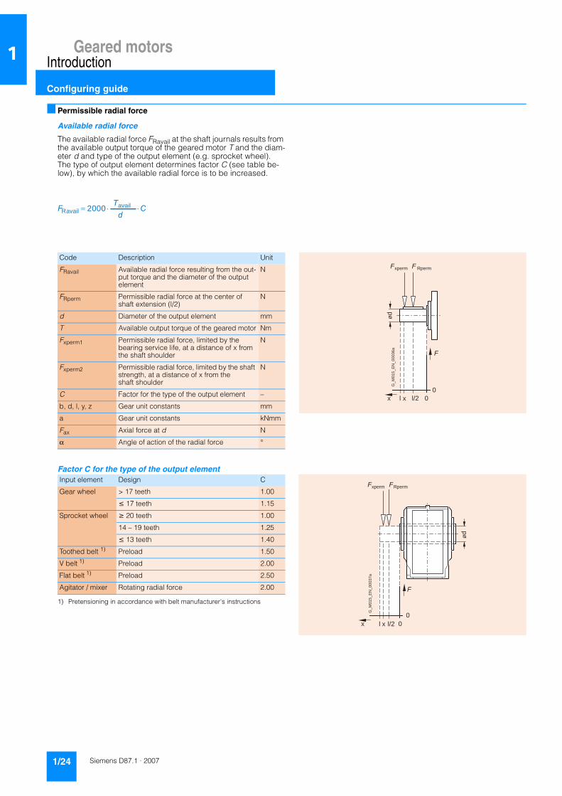
■ Permissible radial force
Available radial force
The available radial force FRavail at the shaft journals results from the available output torque of the geared motor T and the diam-eter d and type of the output element (e.g. sprocket wheel). The type of output element determines factor C (see table be-low), by which the available radial force is to be increased.
Factor C for the type of the output element
1) Pretensioning in accordance with belt manufacturer's instructions
availRavail 2000
dT
F ⋅= C⋅
Code Description Unit
FRavail Available radial force resulting from the out-put torque and the diameter of the output element
N
FRperm Permissible radial force at the center of shaft extension (l/2)
N
d Diameter of the output element mm
T Available output torque of the geared motor Nm
Fxperm1 Permissible radial force, limited by the bearing service life, at a distance of x from the shaft shoulder
N
Fxperm2 Permissible radial force, limited by the shaft strength, at a distance of x from the shaft shoulder
N
C Factor for the type of the output element –
b, d, l, y, z Gear unit constants mm
a Gear unit constants kNmm
Fax Axial force at d N
α Angle of action of the radial force °
Input element Design C
Gear wheel > 17 teeth 1.00
≤ 17 teeth 1.15
Sprocket wheel ≥ 20 teeth 1.00
14 – 19 teeth 1.25
≤ 13 teeth 1.40
Toothed belt 1) Preload 1.50
V belt 1) Preload 2.00
Flat belt 1) Preload 2.50
Agitator / mixer Rotating radial force 2.00
ød
F
l l/2 00
x x
Fxperm F Rperm
G_M
015_
EN
_000
36a
00
x
F
ød
l l/2x
G_M
015_
EN
_000
37a
xperm FRpermF

Geared motorsIntroduction
Configuring guide
1/25Siemens D87.1 · 2007
1
Permissible radial force
The permissible radial force FRperm is determined by the re-quired bearing service life, among other things. The nominal ser-vice life Lh10 is determined in accordance with ISO 281. The bearing service life can be calculated for special operating conditions on request, based on the calculation procedure for the modified service life Lna.
Furthermore, the permissible radial force is determined by the housing and shaft strength of the gear unit. The selection tables specify the permissible radial force FRperm for the input shafts. These values refer to the point of load at the center of the shaft extension and are minimum values, which apply to the worst possible conditions in the gear unit (force angle, mounting posi-tion, direction of rotation).
If the point of load is not at the center of the shaft extension, the permissible radial force must be calculated as follows: the smaller value of Fxperm1(bearing service life) and Fxperm2 (shaft strength) is the permissible radial force. The calculation does not include additional axial forces.
If the direction of rotation of the output shaft and the additional axial forces are known, or the values in the table are insufficient, our drive experts have to perform the calculation. Our agitator and mixer drives allow you to achieve higher permissible radial forces. These drives are particularly well suited to large and ro-tating radial forces.
Permissible radial force in accordance with bearing service life for all gear unit types:
Permissible radial force in accordance with shaft strength for helical and worm gear units:
Permissible radial force in accordance with shaft strength for bevel helical, parallel shaft, and helical worm gear units:
The shaft strength only has to be calculated for solid shafts, with hollow shafts this step can be omitted.
Higher permissible radial forces
The permissible radial force load can be increased, taking the angle of force action α and the direction of rotation into account. Installing reinforced bearings also means that higher loads are permitted on the input shaft.
Permissible axial loads
If no transverse force load is present, an axial force Fax (tension or compression) of around 50 % of the specified radial force with standard bearings can be achieved for gear unit sizes 18 to 148.
You can use our "Calculation of input shaft bearing arrangement" assistant in the MOTOX Configurator to calculate the permissi-ble forces. Combined forces with an axial and a radial compo-nent can also be calculated. Please contact us in case of doubt.
x) (zyFF+
⋅= Rperm1xperm
x) (baF+
=2xperm
xaF =2xperm
G_D
087_
XX_0
0014
a
Fax Fr
l
Fr
x

Geared motorsIntroduction
Configuring guide
1/26 Siemens D87.1 · 2007
1
■ Determining the operating mode
The powers specified in the power tables apply to the S1 oper-ating mode (continuous duty with constant load) according to EN 60034-1. The same regulation defines the groups of operat-ing modes specified below:
Operating mode S1 · Continuous duty
Operating modes in which starting and electrical braking do not affect the overtemperature of the stator winding of the motor:
Operating mode S2:
Short-time duty
Operating times of 10, 30, 60, and 90 min. are recommended. After each period of duty the motor remains at zero current until the winding has cooled down to the coolant temperature.
Operating mode S2 · Short-time duty
Operating mode S3:
Intermittent duty
Starting does not affect the temperature. Unless any agreement is made to the contrary, the cycle duration is 10 minutes. Values of 15 %, 25 %, 40 %, and 60 % are recommended for the cyclic duration factor.
Operating mode S3 · Intermittent periodic duty
Operating mode S6:
Continuous duty with intermittent loading
Unless any agreement is made to the contrary, the cycle dura-tion here is also 10 minutes. Values of 15 %, 25 %, 40 %, and 60 % are recommended for the load duration factor.
G_D087_EN_00018 Time
Load
t B
t B Load duration
G_D087_EN_00019 Time
Load
t B
t B Load duration
G_D087_EN_00020 Time
Load
t B t Stt s
t St Standstill timet s Cycle durationt B Load duration
Cyclic duration factorbased on 10 min
t Bt B t St+= · 100%
tP tVtS
Load
Time
G_D
087_
EN
_000
21
Cycle durationOperating time with constant loadIdle time
tPtV
Cyclic duration factor (CDF)
tP=
tS
tS

Geared motorsIntroduction
Configuring guide
1/27Siemens D87.1 · 2007
1
■ Determining the operating mode (continued)
Operating mode S10:
Duty with discrete constant loads
In this mode a maximum of four discrete loads are available, of which each load achieves the thermal steady state. A load of the same value as the one used in S1 operating mode should be selected for this operating mode.
Operating modes in which starting and braking have a corresponding effect on the overtemperature of the stator winding and of the rotor cage:
Operating mode S4:
Intermittent duty where starting affects the temperature
Operating mode S4 · Intermittent periodic duty with starting
Operating mode S5:
Intermittent duty where starting and braking affects the temperature
For the S4 and S5 operating modes, this code should be fol-lowed by the cyclic duration factor, the mass moment of inertia of the motor (JM), and the mass moment of inertia of the load (JLoad), both based on the motor shaft.
Unless any agreement is made to the contrary, the cycle dura-tion here is also 10 minutes. Values of 15 %, 25 %, 40 %, and 60 % are recommended for the cyclic duration factor.
Pref
t1 t2 t3 t4
P 1 P 2 P 3
P 4
tS
Time
Load
G_D
087_
EN
_000
22
PiPref
Constant load within one load cycleReference loadCycle durationtS
t B t Stt s
t A
G_D087_EN_00023 Time
Load
t B t Stt s
t A
t St Standstill timet s Cycle durationt B Load duration
Cyclic duration factor based on 10 min =
t Bt B t St+ · 100%t A +
t A +
t A Starting time
tPtD
Ft tStSt
Load
Time
G_D
087_
EN
_000
24
Cycle durationStarting timeOperating time with constant loadTime with electrical braking
tPtF
Standstill time with windings at zero currentt St
tD
Cyclic duration factor (CDF)
tD=+ tP + tF
tS
tS

Geared motorsIntroduction
Configuring guide
1/28 Siemens D87.1 · 2007
1
■ Determining the operating mode (continued)
Operating mode S7:
Continuous-operation periodic duty with starting and braking
For the S7 and S8 operating modes, the mass moment of inertia of the load (JLoad) based on the motor shaft must be known.
Operating mode S8:
Continuous-operation duty with non-periodic load and speed variations (inverter-fed operation)
Most of the intermittent operating conditions which occur in real situations are a combination of the operating modes defined above. All operating conditions must be specified in order to ac-curately define a suitable motor.
Operating mode S9:
Continuous-operation duty with non-periodic load and speed variations (inverter-fed operation)
Most of the intermittent operating conditions which occur in real situations are a combination of the operating modes defined above. All operating conditions must be specified in order to ac-curately define a suitable motor.
tP tFtD tS
Load
Time
G_D
087_
EN
_000
15
Cycle durationStarting timeOperating time with constant loadTime with electrical braking
tPtF
tD
Cyclic duration factor = 1
tS
tP1tD tF1tP2 tF2
tP3
tSLo
ad
Time
G_D
087_
EN
_000
16
Cycle durationStarting timeOperating time with constant load (P1, P2, P3)Time with electrical braking (F1, F2)
tPtF
tD
Cyclic duration factor (CDF)
tD=+ t P1 t F1·
+ t P2 t F2·+ t P3
tS
tS tS tS
tStD
tSttP
tF
Load
Time
G_D
087_
EN
_000
17
Starting timeOperating time with constant loadTime with electrical braking
tPtF
Standstill time with windings at zero currenttStTime with overloadtS
tD
Geared motorsIntroduction
Configuring guide
1/29Siemens D87.1 · 2007
1
■ Determining the operating mode (continued)
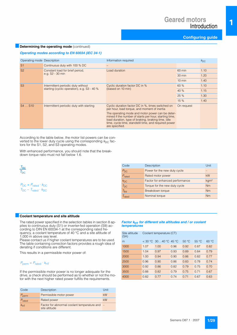
Operating modes according to EN 60034 (IEC 34-1)
According to the table below, the motor list powers can be con-verted to the lower duty cycle using the corresponding kDC fac-tors for the S1, S2, and S3 operating modes.
With enhanced performance, you should note that the break-down torque ratio must not fall below 1.6.
■ Coolant temperature and site altitude
The rated power specified in the selection tables in section 8 ap-plies to continuous duty (S1) or inverter-fed operation (S9) ac-cording to DIN EN 60034-1 at the corresponding rated fre-quency, a coolant temperature of 40 °C and a site altitude of 1,000 m above sea level. Please contact us if higher coolant temperatures are to be used. The table containing correction factors provides a rough idea of derating if conditions are different.
This results in a permissible motor power of:
If the permissible motor power is no longer adequate for the drive, a check should be performed as to whether or not the mo-tor with the next higher rated power fulfills the requirements.
Factor kHT for different site altitudes and / or coolant temperatures
Operating mode Description Information required kDC
S1 Continuous duty with 100 % DC –
S2 Constant load for brief period, e.g. S2 - 30 min
Load duration 60 min 1.10
30 min 1.20
10 min 1.40
S3 Intermittent periodic duty without starting (cyclic operation), e.g. S3 - 40 %
Cyclic duration factor DC in % (based on 10 min)
60 % 1.10
40 % 1.15
25 % 1.30
15 % 1.40
S4 … S10 Intermittent periodic duty with starting Cyclic duration factor DC in %, times switched on per hour, load torque, and moment of inertiaThe operating mode and motor power can be deter-mined if the number of starts per hour, starting time, load duration, type of braking, braking time, idle time, cycle time, standstill time, and required power are specified.
On request
DC
BdTT
PDC = Prated · kDCTDC ~ Trated · kDC
Code Description Unit
PDC Power for the new duty cycle –
Prated Rated motor power kW
kDC Factor for enhanced performance kgm²
TDC Torque for the new duty cycle Nm
TBd Breakdown torque Nm
Trated Nominal torque Nm
Code Description Unit
Pperm Permissible motor power kW
Prated Rated power kW
kHT Factor for abnormal coolant temperature and site altitude
–
Pperm = Prated · kHT
Site altitude (SA)
Coolant temperature (CT)
m < 30 °C 30…40 °C 45 °C 50 °C 55 °C 60 °C
1000 1.07 1.00 0.96 0.92 0.87 0.82
1500 1.04 0.97 0.93 0.89 0.84 0.79
2000 1.00 0.94 0.90 0.86 0.82 0.77
2500 0.96 0.90 0.86 0.83 0.78 0.74
3000 0.92 0.86 0.82 0.79 0.75 0.70
3500 0.88 0.82 0.79 0.75 0.71 0.67
4000 0.82 0.77 0.74 0.71 0.67 0.63

Geared motorsIntroduction
Configuring guide
1/30 Siemens D87.1 · 2007
1
■ Selecting the brake
MOTOX geared motors can be supplied with fail-safe spring-operated disk brakes in order to reduce the motor's follow-on time or to hold loads, for example. Our MODULOG modular sys-tem can be used to assign / attach several brake sizes to one motor size. See Chapter 8 for information on assigning brake sizes to motor sizes, and on possible brake options.
The following information is required in order to select and check the brake:• Speed• Load torque• Moments of inertia• Number of starts
■ Selecting the braking torque
The braking torque must be selected in accordance with the par-ticular drive scenario. The following criteria are crucial when it comes to making this selection: static safety, required braking time, permissible deceleration rate, and possible braking dis-tance and brake wear. The ambient conditions and number of starts are also important. Our drive experts will be able to pro-vide optimum brake sizing.
In principle the selection is made according to the formula:
Where k = 1.0 - 2.5 is selected. As a general rule of thumb, the factor for horizontal motion is around 1.0 - 1.5 and for vertical motion around 2.0 - 2.5. However, the exact specification of the braking torque depends to a large extent on the particular oper-ating conditions.
Operating time of the brake
The time it takes the motor to come to a standstill comprises the following components: the application time of the brake t1 and the braking time tbr. The first is the time it takes the brake to reach 90 % of its braking torque. This time may be circuit- and actua-tion-dependent. This information is provided for each brake in Chapter 8. The braking time can be calculated as follows:
If Tx supports the braking operation, Tx is positive, otherwise it is negative.
Braking distance and positioning accuracy
Braking distance sbr is the distance traveled by the driven ma-chine during braking time tbr and application time t1. The formula below applies to horizontal motion and upward ver-tical motion. With linear motion, a positioning accuracy of around ± 15 % can be assumed. However, this can be heavily influ-enced by the condition of the brake.
ηkTT ⋅> xbr
)TTnJJadd(Jt
ηη⋅±⋅⋅⋅++
=xbr
brxMbr (9,55
)
sbr = v · 100 · (t1 + 0,5 · tbr)
Code Description Unit
Tbr Rated braking torque Nm
Tx Load torque Nm
k Factor for taking operating conditions into account
kgm²
η Efficiency %
tbr Braking time s
t1 Application time of the brake ms
JM Mass moment of inertia of the motor kgm2
Jadd Additional mass moment of inertia (e.g. centrifugal mass or high inertia fan)
kgm2
Jx Reduced mass moment of inertia of the load kgm²
nbr Braking speed rpm
sbr Braking distance –
v Conveying speed m/s
W Friction energy per braking operation J
Qperm Permissible operating energy J
Lrated Service life of the brake lining until readjustment
–
Lratedmax Service life of the brake lining until replacement
v Conveying speed m/s
WV Friction energy until the brake is adjusted MJ
Wtot Friction energy until the brake lining is replaced
MJ
Z Number of starts 1/h

Geared motorsIntroduction
Configuring guide
1/31Siemens D87.1 · 2007
1
■ Selecting the braking torque (continued)
Braking energy per braking operation
The braking energy W per braking operation comprises the en-ergy of the moments of inertia to be braked and the energy which must be applied in order to brake against a load torque:
Tx is positive if the load torque is working against the braking torque (horizontal motion, upward vertical motion).
Tx is negative if it supports the braking operation (downward vertical motion).
The permissible operating energy Qperm must be checked against the relevant number of starts using the "Permissible operating energy" diagram (see Chapter 8). This is of particular importance for emergency-stop circuits.
Brake service life
The brake lining wears due to friction, which increases the air gap and the application time of the brake. The air gap can be re-adjusted. The friction lining should be replaced after it has been readjusted a certain number of times.
Service life of the brake lining until readjustment:
Service life of the brake lining until replacement:
182,5)( br
2M
br
br nJxJpermJTxT
TW ⋅⋅++⋅
⋅±=
ηη
W < Qperm
ZWWVL⋅
=rated
ZWWtotL
⋅=ratedmax

Geared motorsIntroduction
Configuring guide
1/32 Siemens D87.1 · 2007
1
■ Determining the permissible number of starts Zperm
A high number of starts means that the motor winding will be subject to a thermal load. The permissible no-load operating fre-quency Z0 for brake motors is specified in the no-load operating frequency tables. The permissible number of starts Zperm has to be determined for different operating cases. This value is influenced by the corresponding load torque, any additional mass moment of inertia, the power requirement, and the cyclic duration factor. These can be evaluated using the fac-tors kM, kFI, and kP.
During operation at 60 Hz, the calculated permissible number of starts Zperm must be reduced by 25 %. See the technical data for brakes found in Chapter 8 for the permissible number of starts during operation with function rectifiers.
Additional moment of inertia
Torque during run-up
Code Description Unit
JM Mass moment of inertia of the motor kgm2
Jadd Additional moment of inertia based on the motor shaft
kgm2
kM Factor for taking the counter torque during run-up into account
–
kFI Factor for taking the additional moment of inertiainto account
–
kP Factor for taking the required power and duty cycle into account
–
T1mot Continuous torque of the motor Nm
TH Run-up torque of the motor Nm
P1 Input power of the motor kW
Prated Rated motor power kW
Zperm Permissible number of starts rph
Z0 No-load operating frequency from the list rph
Zperm = Z0 · kM · kFI · kP
0
k FI
0 1 2 3 4 5
G_M
015_
EN
_000
41
M
J
Jadd
kFl =MJ addJ
MJ
0.2
0.4
0.6
0.8
1.0
0.1
0.3
0.5
0.7
0.9
0
k M
0TTH
T H
1
1 -kM = 1T
0.2
0.4
0.6
0.8
1.0
0.1
0.3
0.5
0.7
0.9
0.2 0.4 0.6 0.8 1.0
G_M
015_
EN
_000
40a

Geared motorsIntroduction
Configuring guide
1/33Siemens D87.1 · 2007
1
■ Checking input torques for mounted units
Geared motors are usually integrated, i.e. they are mounted on the gear unit directly and the products are supplied as complete drives. Alternatively, the gear units can also be supplied with various input units for motor mounting. The criteria below must be taken into account, particularly for special motors.
Maximum input speed
We recommend that four-pole motors are mounted in order to achieve optimum gear unit service life. Higher input speeds can have an effect on bearing service life and the gear unit's thermal properties, among other things. See the section titled "Maximum speed", page 1/23.
Permissible radial force of the input unit
Input units A and P can be powered by a V belt drive, for exam-ple. This results in a radial load on the input shaft. The permissi-ble radial forces are specified in the section titled "Input unit".
Maximum input torque
The input units are primarily designed for four-pole standard three-phase AC motors. Considerably higher motor torques, which are above the maximum permissible input torque, may oc-cur with special motors.
First of all, the continuous torque T1mot of the motor and the per-missible input torque of the input unit T1 must be checked, along with the maximum torques (starting, breakdown, and braking). The torques for input units are specified in the section titled "Input unit". Please contact us if you have any questions.
T1 = Permissible input torque of the input unit
T1mot = Continuous torque of the motor
T1max = Temporarily permissible max. input torque of the input unit
T1mot < T1
T1max < 2,5 · T1

Geared motorsIntroduction
General technical data
1/34 Siemens D87.1 · 2007
1
■ Overview of drive sizing data
Code Description Unit Code Description Unit
a Gear unit constant kNmm P1 Input power of the motor kW
b, d, l, y, z Gear unit constants mm P2 Output power of the gear unit kW
C Factor for the type of the output element – PDC Power for the new duty cycle kW
d Diameter of the input element mm Prated Rated motor power kW
DC Cyclic duration factor (CDF) % Pperm Permissible motor power kW
fBtot Service factor of the driving machine – Qperm Permissible operating energy J
fB Service factor of the geared motor – r Radius of the output element m
Fax Axial force at d N sbr Braking distance m
Fr Radial force at the output shaft N t1 Application time of the brake ms
FRavail Available radial force resulting from the output torque and the diameter of the out-put element
N tbr Braking time s
FRperm Permissible radial force at the center of shaft extension (l/2)
N T1 Permissible input torque of the input unit Nm
Fxperm1 Permissible radial force, limited by the bear-ing service life, at a distance of x from the shaft shoulder
N T1mot Continuous torque of the motor Nm
Fxperm2 Permissible radial force, limited by the shaft strength, at a distance of x from the shaft shoulder
N T1max Temporarily permissible max. input torque of the input unit Nm
i Gear ratio – T2 Output torque of the geared motor Nm
J2 Mass moment of inertia based on the input speed of the gear unit
kgm² Tbr Rated braking torque Nm
JLoad All external mass moments of inertia (based on the motor shaft) kgm2
TDC Torque for the new duty cycle Nm
JM Mass moment of inertia of the motor kgm² TH Run-up torque of the motor Nm
Jx Reduced mass moment of inertia of the load kgm2 TBd Breakdown torque Nm
Jadd Additional mass moment of inertia (e.g. centrifugal mass or high inertia fan)
kgm² Trated Nominal torque Nm
k Factor for taking operating conditions into account
– Tavail Available torque of the geared motor Nm
kDC Factor for enhanced performance – Tx Load torque Nm
kFI Factor for taking the additional moment of inertia into account
– v Conveying speed m/s
kHT Factor for abnormal coolant temperature or site altitude
– W Friction energy per braking operation J
kM Factor for taking the counter torque during run-up into account
– Wtot Friction energy until the brake lining is replaced
MJ
kP Factor for taking the required power and duty cycle into account
– WV Friction energy until the brake is adjusted MJ
Lrated Service life of the brake lining until readjustment
– Z Number of starts 1/h
Lratedmax Service life of the brake lining until replacement
– Zperm Permissible number of starts 1/h
MAF Mass acceleration factor – Z0 No-load operating frequency from the list 1/h
n1 Input speed of the motor rpm α Angle of action of the radial force °
n2 Output speed of the gear unit rpm η Efficiency %
nbr Braking speed rpm ϑamb Ambient temperature °C

Geared motorsIntroduction
General technical data
1/35Siemens D87.1 · 2007
1
■ Important drive technology variables
SI unit
Variable Abbreviation Unit abbreviation Relationship or conversion rate *
SI Previously SI Previously
Length (distance) L(s) L, s m m 1 km = 1,000 m
Area A F m2 m2 1 m2 = 100 dm2
Volume V V m3 m3 1 m3 = 1,000 dm3 1 dm3 = 1 l
Plane angle a, b, g a, b, g rad Degrees ° 1 rad = 1 m/m1 L = π/2 rad 1° =π/180 rad
Rotation angle f j Degrees ° 1' = 1°/60; 1'' = 1'/60
Time 1 min = 60 s 1 h = 60 min
Time range t t s s 1 d = 24 h
Duration 1 a = 24 h
Frequency f f Hz 1/s 1 Hz = 1/s
Speed n n rpm rev/minrpm
Revolutions per minute
Velocity v v m/s m/s 1 km/h =
AccelerationFree-fall acceleration
ag
bg
m/s2 m/s2 g = 9.81 m/s2
Angular velocity w W rad/s 1/s
Angular acceleration a x rad/s2 1/s2
Mass m m kg kg 1
Density d kg/dm3 kg/dm3 103
ForceWeight force
FG
P, KG
N kp 9.81 1 N = 1 kg · 1 m/s2
Pressure
Mechanical tension
p
σ
p
σ
PaN/m2
N/mm2kp/cm2
kp/mm2
1 Pa = 1 N/m2
9.81 · 104
9.81
WorkEnergyQuantity of heat
WWQ
AEQ
Jkpmkcal
9.814,1871 J = 1 Nm = 1 Ws
Force torqueTorqueBending torque
TMtMdMb
Nm kpm9.811 Nm = 1 J
Power P N W PS 735.5; 1 W = 1 J/s = 1 Nm/s =
Mass moment of inertia J q kgm2 kpm2 9.81
* The numerical value of a variable in previously used units multiplied by the conversion rate gives the numerical value of the variable in the SI unit.
kgm²s³
13.6
m/s

Geared motorsIntroduction
General technical data
1/36 Siemens D87.1 · 2007
1
Important drive technology variables (continued)
SI unit
Variable Abbreviation Unit abbreviation Relationship or conversion rate *
SI Previously SI Previously
Dynamic viscosity h h Pa · s P 10-1
Kinematic viscosity u u m2/s St 10-4
Electrical current intensity I I A A 1 A = 1 W/V = 1 V/Ω
Electrical voltage U U V V 1 V = 1 W/A
Electrical resistance R R W W 1 Ω = 1 V/A = 1/S
Electrical conductance G G S S 1 S = 1/Ω
Electrical capacitance C C F F 1 F = 1 C/V
ElectricCharge
Q Q C C 1 C = 1 A · s
Inductance L L H H 1 H = 1 Vs/A
Magnetic flux densityInduction
B B T G 104 1 T = 1 Wb/m2
Magnetic field strength H H A/m A/m
Magnetic flux f f Wb M 108
1 Wb = 1 V · s
Temperature T(ϑ) t K(°C) °C 0 K = -273.15°C

Geared motorsIntroduction
General technical data
1/37Siemens D87.1 · 2007
1
■ Overview
MOTOX geared motors are available in an almost infinite number of combinations for adaptation to a wide range of drive scenar-ios. All the usual additional components and variants are also of-fered.
Made-to-measure solutions for all kinds of drive technology tasks are achieved with different gear unit types (helical, parallel shaft, bevel helical, helical worm, and worm), combined with motors by means of modular mounting technology.
■ Designs in accordance with standards and specifications
Energy-saving motors with European efficiency classification in accordance with EU/CEMEP (European Committee of Manufac-turers of Electrical Machines and Power Electronics)
Low-voltage motors in the power range 1.1 to 90 kW, 2-pole and 4-pole are marked in accordance with the EU/CEMEP agree-ment with the efficiency class (Improved Efficiency) or
(High Efficiency).
The active parts of the motor have been optimized in order to meet the requirements of efficiency classes and . The procedure for calculating the efficiency is based on the loss-summation method according to IEC 60034-2.
Motors for the North American market
For motors which comply with North American regulations (NEMA, CSA, UL, etc.), a check must always be performed as to whether or not the motors will be used in the USA or Canada and whether they could be subject to state laws.
Minimum efficiencies required by law
In 1997, an act was passed in the USA to define minimum effi-ciencies for low-voltage three-phase AC motors (EPACT = En-ergy Policy Act). An act is in force in Canada that is largely iden-tical, although it is based on different verification methods. The efficiency is verified for these motors for the USA using IEEE 112, Test Method B and for Canada using CSA-C390. Apart from a few exceptions, all low-voltage three-phase AC motors ex-ported to the USA or Canada must comply with the legal effi-ciency requirements.
The law demands minimum efficiency levels for motors with a voltage of 230 and 460 V at 60 Hz, in the power range 1 to 200 HP (0.75 to 160 kW) with 2, 4, and 6 poles. Explosion-proof motors must also be included. The EPACT effi-ciency requirements exclude, for example: Motors whose size power classification does not correspond with the standard se-ries according to NEMA MG1-12, flange-mounting motors with-out feet, brake motors, inverter-fed motors.
For more information on EPACT: http://www.eren.doe.gov/
Special requirements for the USA: Energy Policy Act
The act lays down that the nominal efficiency at full load and a "CC" number (Compliance Certification) must be included on the rating plate. The "CC" number is issued by the US Department of Energy (DOE). The following information is stamped on the rating plate of EPACT motors which must be marked by law: nominal efficiency (service factor SF 1.15), design letter, code letter, CONT, CC no. CC 032A (Siemens), and NEMA MG1-12.
Special requirements for Canada: CSA – Energy Efficiency Verification
These motors fulfill the minimum efficiency requirements laid down by the CSA standard C390. These motors can be ordered and feature the CSA-E mark on their rating plates.
NEMA – National Electrical Manufacturers Association
The motors with increased efficiency according to EPACT are designed to meet the NEMA MG1-12 electrical standard and are marked accordingly.
The mechanical design of all motors is compliant only to IEC, not to NEMA dimensions.
All motors correspond to NEMA Design A (i.e. standard torque characteristic in accordance with NEMA and no starting current limitation).
For Design B, C, and D, a special version is required (on request).
Data on the rating plate: rated voltage (voltage tolerance of ±10 %) or rated voltage range (voltage tolerance ±5 %), nominal efficiency, design letter, code letter, CONT, and NEMA MG1-12.
Order code for NEMA design: N65
Geared motorsIntroduction
General technical data
1/38 Siemens D87.1 · 2007
1
■ Designs in accordance with standards and specifications (continued)
UL-R – Underwriters Laboratories Inc. listing
The motors based on the LA/LG basic series are listed for up to 600 V by Underwriters Laboratories Inc. ("Recognition Mark" = R/C).
"UL Recogn. Mark" is included on the rating plate of the motor.
In addition, the motor is designed to meet the NEMA MG1-12 electrical standard and includes the following data on the rating plate: rated volt-
age (voltage tolerance of ±10 %) or rated voltage range (voltage tolerance ±5 %), nominal efficiency, design letter, code letter, CONT, and NEMA MG1-12.
Externally or internally mounted components such as:• Motor protection• Heating element• External fan unit• Brake• Encoder• Power connection• Plug connection
are UL-R/C, CSA, or C-US listed or used by manufacturers in ac-cordance with regulations. It may have to be decided whether the motor is suitable for the application. The motors can be op-erated on a frequency inverter at 50/60 Hz.
CSA – Canadian Standard Association
Motors based on the LA/LG basic series are approved for up to 690 V in accordance with the Canadian regulations of the "Canadian Standard Association" (CSA). Externally or internally mounted components which are used are listed by CSA or are used by manufacturers in accordance with regulations. The CSA mark and the rated voltage (voltage tolerance of ±10 %) or rated voltage range (voltage tolerance ±5 %) are included on the rating plate.
When energy-saving motors (1LA9, 1LG6) are ordered, they also include the CSA-E mark on the rating plate.
Export of low-voltage motors to China
CCC – China Compulsory Certification
"Small power motors" which are exported to China must be certified up to a rated power of:
2-pole: ≤ 2.2 kW
4-pole: ≤ 1.1 kW
6-pole: ≤ 0.75 kW
8-pole: ≤ 0.55 kW
The LA motors which must be certified are certified by the CQC (China Quality Cert. Center). When one of these motors is ordered, the logo "CCC (Safety Mark)" is included on the rating plate and the packaging.
Notes:
Chinese customs checks the need for certification of imported products by means of the commodity code.
The following do not need to be certified:• Motors imported to China which have already been installed
in a machine• Repair parts
Order code for CCC design: N67
Export of geared motors and gear units to Russia
GOST-R conformity
The following gear units can be supplied separately or as part of geared motors, certified according to GOST-R:• Helical gear units• Bevel helical gear units• Parallel shaft gear units• Helical worm gear units• CAVEX worm gear units
Order code for GOST geared motors or gear units: N30
VIK design
Geared motors up to motor size 160 L can be supplied in accor-dance with VIK (Verband der Industriellen Energie- und Kraft-wirtschaft e.V.) technical requirements on request.
®

Geared motorsIntroduction
General technical data
1/39Siemens D87.1 · 2007
1
■ Designs in accordance with standards and specifications (continued)
Classified energy-saving motors for an efficient energy balance
Depending on requirements, energy-saving motors are avail-able for an efficient energy balance – for EU requirements in ac-cordance with CEMEP (European Committee of Manufacturers of Electrical Machines and Power Electronics) and for the North American market in accordance with EPACT (US Energy Policy Act).
Efficiency requirements according to CEMEP
CEMEP classifies efficiency levels for 2-pole and 4-pole motors with powers of 1.1 to 90 kW. Three efficiency classes are defined:• EFF1 (High Efficiency motors)• EFF2 (Improved Efficiency motors)• EFF3 (Conventional Efficiency motors)
At a glance: EU/CEMEP for Europe• Status:
Voluntary compliance with efficiency classification• Covers:
2-pole, 4-pole 50 Hz squirrel-cage motors from 1.1 to 90 kW (at 400 V)
• Required marking:Efficiency class on the motor rating plate η rated, η 3/4 load and efficiency class in the documentation
Efficiency requirements according to EPACT
In 1997, an act was passed in the USA to define minimum effi-ciencies for low-voltage three-phase AC motors (EPACT).
An act is in force in Canada that is largely identical, although it is based on different verification methods. The efficiency is veri-fied for these motors for the USA using IEEE 112, Test Method B and for Canada using CSA-C390.
Apart from a few exceptions, all low-voltage three-phase AC mo-tors imported into the USA or Canada must comply with the legal efficiency requirements.
The law demands minimum efficiency levels for motors with a voltage of 230 and 460 V at 60 Hz, in the power range 1 to 200 HP (0.75 to 160 kW) with 2, 4, and 6 poles. Explosion-proof mo-tors must also be included.
The EPACT efficiency requirements exclude, for example:• Motors whose size power classification does not correspond
with the standard series according to NEMA MG1-12• Flange-mounting motors• Brake motors• Inverter-fed motors• Motors with design letter C and higher.
EPACT lays down that the nominal efficiency at full load and a "CC" number (Compliance Certification) must be included on the rating plate. The "CC" number is issued by the US Department of Energy (DOE).
The following information is stamped on the rating plate of EPACT motors which must be marked by law:• Nominal efficiency• Design letter• Code letter• CONT• CC no. CC 032A (Siemens) and NEMA MG1-12.
At a glance: EU/CEMEP for North America• Status:
Minimum efficiencies required by law• Covers:
2-pole, 4-pole, and 6-pole 60 Hz squirrel-cage motors from 1 to 200 HP (0.75 to 150 kW) for 230 V and/or 460 V 60 Hz
• Required marking:Efficiency N on the motor rating plate.
%
70
75
1 10 20 40
G_D
081_
EN
_000
59
100
Prated
kW2 4 6 8 60
80
85
90
95
rated

Geared motorsIntroduction
General technical data
1/40 Siemens D87.1 · 2007
1
■ Energy-saving motors in accordance with CEMEP/EPACT
The product range of geared motors exclusively comprises motors in the EU efficiency classes EFF1 "High Efficiency" and EFF2 "Improved Efficiency". The active parts of the motor have been optimized in order to meet the requirements of the CEMEP efficiency classes EFF1 and EFF2. The procedure for calculating the efficiency is based on the loss-summation method according to IEC 60034-2. With these energy-saving motors a significant reduction in energy costs can be achieved as compared to con-ventional motors according to EFF3.
EPACT motors from Siemens are available CC-certified, marked with the number CC32A on the rating plate and, optionally, also according to UL with the Recognition Mark. Siemens offers mo-tors with the CSA Energy Efficiency Verification Mark especially for the Canadian market.
■ Explosion protection as per ATEX
In the European market ATEX Directive 94/9/EC applies to all types of equipment used in potentially explosive atmospheres - which include geared motors. It became mandatory on July 1, 2003 and has unrestricted validity for the use of all geared mo-tors within the European Union. Other countries too have now complied with this regulation.
Helical gear units, parallel shaft gear units, bevel helical gear units, and helical worm gear units are available to comply with this Directive. A wide range of gear unit and motor designs and sizes are approved for zones 1, 2 (gases) and zones 21 and 22 (dusts).
MOTOX-N geared motors can be provided for categories 2 and 3.
Use in explosive atmospheres caused by gases is permissible for temperature classes T1 to T4. With use in explosive atmo-spheres caused by dust, the maximum temperature of 120 °C must be taken into consideration for the gear unit. An oil level sensor can be integrated for monitoring in inaccessible areas.
Motors are available in the following protection types: flameproof enclosure (Exd), flameproof enclosure and terminal box with in-creased safety (Exde), increased safety (Exe), and non sparking (Exn) as well as motors for dust explosion protection.
Improved efficiency High efficiency
200 kW
90 kW
200 HP
1 HP
G_D087_EN_00002a
1.1 kW
0.06 kW
CEMEPstandard
CEMEPstandard
EPACTlaw
MOTOX geared motorsEFF2 motors
MOTOX geared motorsEFF1/EPACT motors
Ex-atmosphere / Zone Category Frequency
G (gas and steam) D (dust)
0 20 1 Continuously or long-term
1 21 2 Intermittent
2 22 3 Rarely or briefly

Geared motorsIntroduction
General technical data
1/41Siemens D87.1 · 2007
1
■ Standards
The motors comply with all applicable international (IEC), European (EN, CENELEC), and national (DIN/VDE) standards:
The main dimensions of all gear units comply with the following DIN standards:
Shaft heights DIN 747 Shaft ends DIN 748/1 Mounting flange DIN 42948 Concentricity of shaft extensions, concentricityand axial eccentricity of mounting flange DIN 42955 Parallel keys DIN 6885/1 Second motor shaft end DIN 748/3 Center holes in shaft ends DIN 332/2
IEC EN / HD DIN / VDE TitleIEC 60027-4 HD 245.4 DIN 1304-7 Letter symbols for physical quantities,
symbols to be used for electrical machinesIEC 60034-1 EN 60034-1 DIN EN 60034-1
VDE 0530-1Rotating electrical machines:- Rating and performance
IEC 60034-2 EN 60034-2 DIN EN 60034-2VDE 0530-2
- Methods for determining losses and efficiency from tests (excluding machines for traction vehicles)
IEC 60034-5 EN 60034-5 DIN EN 60034-5VDE 0530-5
- Degrees of protection provided by integral design of rotating electrical machines (IP code) - Classification
IEC 60034-6 EN 60034-6 DIN EN 60034-6VDE 0530-6
- Methods of cooling (IC Code)
IEC 60034-7 EN 60034-7 DIN EN 60034-7VDE 0530-7
- Classification of types of construction, mounting arrangements and terminal box position (IM code)
IEC 60034-8 EN 60034-8 DIN EN 60034-8VDE 0530-8
- Terminal markings and direction of rotation
IEC 60034-9 EN 60034-9 DIN EN 60034-9VDE 0530-9
- Noise limits
IEC 60034-12 EN 60034-12 DIN EN 60034-12VDE 0530-12
- Starting performance of single-speed three-phase cage induction motors
IEC 60034-14 EN 60034-14 DIN EN 60034-14VDE 0530-14
- Mechanical vibration of certain machines with shaft heights 56 mm and higher
IEC TS 60034-17 – DIN IEC/TS60034-17VDE 0530-17
- Cage induction motors when fed from converters - Application guide
IEC 60038 HD 472 DIN IEC 60038 IEC standard voltages– EN 50347 DIN EN 50347 General purpose three-phase induction motors
having standard dimensions and outputsIEC 60085 HD 566 DIN IEC 60085 Thermal evaluation and designation of electrical
insulationIEC 60445 EN 60445 DIN EN 60445 Identification of equipment terminals and conductor
terminationsIEC 60529 EN 60529 DIN EN 60529
VDE 0470-1Degrees of protection provided by enclosures (IP code)
– EN 50262 DIN EN 50262 Cable glands for electrical installations– – EDIN 42925 Terminal box cable entries for three-phase cage
induction motors at rated voltages from 400 V to 690 V

Geared motorsIntroduction
General technical data
1/42 Siemens D87.1 · 2007
1
■ Fits
Flange form A, C:
b1 ≤ ø 230 = j6
b1 > ø 230 = h6
Drive-side shaft end:
d1 < ø 55 : k6
d1 ≥ ø 55 : m6
See the dimension drawings for other fits.
■ Degrees of protection
The geared motors are supplied with IP55 to standards IEC 60529 (gear units) and IEC 60034-5 (motors). For higher degrees of protection for motors, see Chapter 8, "Motor degrees of protection".
■ Direction of rotation of geared motors
The three-phase AC motors are configured so the motor shaft ro-tates clockwise (IEC 60034-8).The direction of rotation of the gear unit output shaft can be re-versed by swapping two external connection wires on the motor.
Specifying the direction of rotation for geared motors and gear units with backstop
It is necessary to specify the desired direction of rotation of the input shaft when ordering a gear unit with backstop. The direc-tion of rotation is determined by the front view of the input shaft (shaft end face). With parallel shaft, bevel helical, and helical worm gear units, it is again necessary to specify the side on which the input shaft is located, i.e. either "Input side A" or "Input side B". The input side is defined by specifying the mount-ing position.
Direction of rotation of the geared motor when viewing the input shaft
Output shaft direction of rotation order codes:
Clockwise: K18Counterclockwise: K19
■ Powers and torques
The specified powers and torques refer to standard designs, mounting positions B3../ B5../H01 and other comparable mount-ing positions, whereby the first stage is not completely immersed in oil. Normal ambient conditions and standard lubrication are also required.
■ Speeds
The specified output speeds are guide values, rounded to the first decimal place. You can use the rated motor speed and the gear unit speed to calculate the rated drive speed. Please note that the actual output speed will depend on the motor load and the power supply conditions.
Clockwise Counterclockwise

Geared motorsIntroduction
General technical data
1/43Siemens D87.1 · 2007
1
■ Noise
Noise emitted by the motors during mains operation
Noise is measured in accordance with DIN EN ISO 1680 in a dead room. The noise level is specified as A-weighted measur-ing surface sound pressure level LpfA in dB (A). This value is the spatial average value of the sound pressure levels measured at the measuring surface. The measuring surface is a cube 1 m away from the surface of the motor. The sound power level is also specified as LWA in dB (A).
The values specified in the motor selection tables apply to the motor without gear unit at 50 Hz (see the selection and ordering data in the corresponding sections of the catalog). The tolerance is +3 dB. At 60 Hz, the values are approximately 4 dB (A) higher. Please enquire about noise levels for pole-changing motors, geared motors, and inverter-fed motors.
Noise emitted by the geared motors
The geared motors do not exceed the permissible noise levels defined for gear units in VDI guideline 2159 and for motors in EN 60034. Experience tells us that the geared motors emit a noise that is around 3 - 5 dB (A) louder than that emitted by the motors. Precise data is available on request.
■ Weight of geared motors
The weight data contained in the dimension drawings are aver-aged values and do not take account of oil. The weights vary ac-cording to the gear unit design and size. The oil quantity de-pends on the mounting position. You will find oil quantity guide values in the gear unit chapters, "Oil quantities" section. The exact weight of the drive will be specified on the order con-firmation.
■ Three-phase AC motors
Three-phase AC motors are designed to be perfectly coordi-nated with the gear unit system and can be supplied with or with-out a brake.
The motor series covers sizes 71 to 315. The powers of the 2-, 4-, 6-, and 8-pole motors are classified in accordance with IEC. Pole-changing designs with pole numbers 8/2; 8/4; 4/2; 6/4 are available on request. The housings of mo-tors up to size 160 are made from high-quality aluminum alloy. Housings for sizes 180 and above are made from gray cast iron.
■ Brakes
The motors can be supplied with spring-operated disk brakes. These are double-disk brakes, which are spring-operated at zero current.
The torque can be set within certain limits for every brake size.

Geared motorsIntroduction
General technical data
1/44 Siemens D87.1 · 2007
1
■ Lubricants
All gear units are filled with lubricant at the factory. The lubricants used meet the requirements of DIN 51502. The gear units are filled with varying oil quantities (see operating instructions and rating plate) depending on their mounting position. If no specifications are made to the contrary, the standard lubri-cant is used.
Required quality of gear lubricants
The oils used in the MOTOX gear units are subject to stringent quality control. For MOTOX gear units, only CLP-quality oils are approved which contain ingredients to DIN 51517-3 for improve-ment of corrosion protection, resistance to ageing, and which re-duce wear in mixed-friction areas. The scuffing resistance in the FZG test to DIN 51354-2 must comply with stage 12 or higher under A/8.3/90 test conditions. In the FE-8 rolling bearing test to DIN 51817-3 rolling element wear must be under 30 mg and cage wear under 100 mg under D-7.5/80-80 test conditions.
In addition, the lubricants must meet the following quality requirements demanded by FLENDER:• Sufficiently high gray-staining resistance in accordance with
FVA 54 gray-staining test• Low degree of foaming with less than 15 % foam formation in
the FLENDER foam test• Suitable for the elastomer material used in the radial shaft
seals of FLENDER gear units• Compatible with residues of corrosion-protection agent and
run-in oils used by FLENDER• Compatible with the paints used by FLENDER in its gear unit
interiors• Compatible with liquid seals between bolted-joint surfaces.
Furthermore, for use in worm gear units:
Low wear, high pitting resistance, and high efficiency (low temperature) in the cylindrical worm gear unit test.
For a list of approved oils from different manufacturers please re-fer to the Operating Instructions BA 7300.

Geared motorsIntroduction
General technical data
1/45Siemens D87.1 · 2007
1
■ Lubricants (continued)
Lubricants for helical gear units E/D/Z, parallel shaft gear unit F, bevel helical gear unit K:
*) On request
Lubricants for bevel helical gear unit B and helical gear unit C:
*) On request
The ambient temperatures are applicable for gear units in stan-dard operation. The data is based on our experience with stan-dard applications. The oil sump temperature is a decisive factor for the service life of the lubricant and depends to a large extent on the gear unit type, gear unit size, transmission ratio, mounting position, input speed, and operating mode.
The data on usage in high, low, and lowest temperature ranges only refers to the lubricant. It may be necessary to take other de-sign measures. Please contact us.
With low ambient temperatures, critical startup characteristics need to be taken into account.
With higher ambient temperatures (> 40 °C), the permissible oil sump temperature must not be exceeded. Please contact us if you require your drive to be thermally tested.
■ Long-term preservation
Helical gear units, parallel shaft gear units, bevel helical gear units, and helical worm gear units can be delivered with a long-term preservation of up to 36 months. The free shaft extensions, sealing elements, and flanges are coated with a protective layer of grease. The gear unit is completely filled with oil for long-term preserva-tion. See the operating instructions for information on storage and commissioning.
Order code for long-term preservation up to 36 months: K17
Area of application Ambient temperature DIN ISO designation Order code
Standard oilsStandard temperature -10 … +40 °C CLP ISO VG 220 K06
Improved oil service life -20 … +50 °C CLP ISO PG VG 220 K07
High temperature usage 0 … +60 °C CLP ISO PG VG 460 K08
Low temperature usage -30 … +50 °C CLP ISO PAO VG 220 K12 *)
Lowest temperature usage -40 … +40 °C CLP ISO PAO VG 68 K13 *)
Physiologically safe oils (for use in the food industry) in acc. with USDA-H1Standard temperature -30 … +40 °C CLP ISO PAO VG 460 K10 *)
Biologically degradable oilsStandard temperature -20 … +40 °C CLP ISO E VG 220 K11 *)
Area of application Ambient temperature DIN ISO designation Order code
Standard oilsStandard temperature 0 … +60 °C CLP ISO PG VG 460 K08
Low temperature usage -20 … +50 °C CLP ISO PAO VG 220 K12 *)
Physiologically safe oils (for use in the food industry) in acc. with USDA-H1Standard temperature -30 … +50 °C CLP ISO PAO VG 460 K10 *)

Geared motorsIntroduction
General technical data
1/46 Siemens D87.1 · 2007
1
■ Paint coat
We offer three high-quality paint systems in various hues to pro-tect drives against corrosion and external influences.
Geared motors of size 38 and above are painted in RAL 5015 (sky blue) with a synthetic resin base as standard. This ensures that they are protected against corrosion for installation in a moderate outdoor climate.
Gear units of size 18 and 28 with an aluminum housing are sup-plied unpainted as standard.
For transport, the bare parts are coated with anti-corrosion paint which will last for a limited amount of time.
Order codes for RAL colors:
5015 sky blue (standard for plastic) L50
7011 iron gray L51
2004 pure orange L52
7031 blue gray (standard for 2-component PUR)L53
7035 light gray (standard for 2-component epoxy)L43
The colors listed above can be specified using order code Y80 and the RAL color code in plain text.
Example:
Reseda green
Order code: Y80*RAL @ 6011*
Paint system Hue Typical area of application
Repaint characteristics*
Chem. phys. resistance
Thermal stability of the paint
Comments
Plastic(standard)
Order code:L02
Standard: RAL 5015
On request: RAL 1003, 1007, 1012, 1018, 1023, 2000, 2004, 3000, 5007, 5009, 5010, 5012, 6011, 6018, 7001, 7011, 7030, 7031, 7032, 7035, 9005, 9006, 9010,others on request
Standard 1-layer paint finish for interior areas
With acrylic coat-ing or synthetic resin paint,can be repainted after 3 days' drying time
Good resistance to detergents, oil and petrol, resistant to temporary exposure to diluted acid and alkaline solutions (≤ 3 %), not resistant to solvents, not resis-tant to steam
-40 ° C … 100 ° C
Short-term up to 140 ° C
Standard paint finish with excellent adhe-sive properties; not suitable for out-door storage or installation
2C PUR(surcharge)
Order code:L03
Standard: RAL 7031
On request:RAL 1003, 1012, 1018, 1023, 2004, 300, 5002, 5007, 5009, 5010, 5012, 5015, 6011, 6018, 7000, 7001, 7011, 7030, 7032, 7035, 9005, 9006, 9010, 9011, 9016,others on request
Standard 2-layer paint finish, espe-cially for outdoor installation or higher anti-corrosion pro-tection requirements
After preliminary rub-down with:2C PUR paint2C epoxy paint
Excellent resistance to oil, grease, petrol, water, sea water, and detergents; good resistance to weather conditions and diluted acid and alkaline solutions (≤ 3 %); good mechanical resistance to abrasion
-40 ° C … 150 ° C Standard paint finish for cooling tower and agitator drives or, if requested, resistance to sea water below deck, etc.
2C epoxy(surcharge)
Order code:L04
Standard: RAL 7035
On request:RAL 1007, 1018, 1023, 2000, 5002, 5007, 5009, 5010, 5015, 6011, 6018, 7001, 7030, 7032, 9010, 9011, others on request
High-quality paint finish for outdoor applications or where exposed to diluted acid and alkaline solutions (≤ 5 %)
After preliminary rub-down with:2C PUR paint2C epoxy paint2C AC paint
Excellent resistance to weak acid and alkaline solutions (≤ 5 %), oil, grease, petrol, cooling emul-sion, salt, solvents; toughened and scratch-resistant coating film
-40 ° C … 150 ° C 2C epoxy paint becomes chalky when installed out-side (without affect-ing quality), high gloss with good mechanical resis-tance
Primed
Order code:L01
(RAL 7032) For repainting: adhesion promoter for all common paint systems, temporary anti-corrosion pro-tection
Very good with:acrylic coating, synthetic resin paint, 2C PUR paint, 2C epoxy paint, SH paint, 2C AC paint
Good resistance to detergents and salt spray and resistant to oil and petrol
-40 ° C … 150 ° C Adhesion promoter with very good adhesive properties and good anti-corro-sion protection
Unpainted
Order code:L00
– For repainting: temporary anti-cor-rosion protection
Very good with: synthetic paint, synthetic resin paint, oil paint, bitumen paint, 2C PUR paint, 2C epoxy paint
– (-40 ° C … 150 ° C) GCI parts, dip-primed, steel parts, primed or zinc-plated, alumi-num and plastic parts, untreated

Geared motorsIntroduction
General technical data
1/47Siemens D87.1 · 2007
1
■ Rating plate and additional plates
In accordance with DIN EN 60034-1, the approximate total weight is specified on the rating plate for all geared motors (as of around 30 kg).
In the standard version, the rating plate is available labeled in in-ternational format or in the English / German language.
An additional rating plate can be supplied loose for all motors.
Order code for additional rating plate: K41
Example of a rating plate:
■ Documentation
The geared motors are supplied with the following documentation as standard:• Operating instructions (paper) incl. spare part documentation
and EC manufacturer's declaration in English / German• Manual Collection (on CD) with all operating instructions in
Czech, Dutch, English, French, German, Italian, Russian, Spanish, and Swedish.
The following documents are optionally available:• Order-specific lists of spare parts• Certificate of compliance with the order EN 10204-2.1 and
works test certificate EN 10204-2.2 for the geared motor• Works test certificate EN 10204-2.2 for the material• Works test certificate EN 10204-3.1 for the gear unit,
tests carried out on:
- The input / output shaft diameter- The concentricity of the input shaft- The concentricity of the input shaft (for solo gear units only)- The torsional backlash- The noise (subjective evaluation).
A works test certificate EN 10204-3.1 for motors can also be produced on request. The following are tested:• The 3 no-load currents of the 3 phases• The power loss during no-load operation• The no-load speed.
G_D087_XX_00059
3 G-Motor 06B8999999/nnn 1000kg2KJ1123-4BA56-4AA6-Z
FZAZ108B-Z68-LA132ZMB4FW-L150/100NHA-IN i= 1036.8(IM) H-01-A ThCl. F IP5550Hz 380-420/660-725V D/Y 18.5/10.7A 9.2kWcosPhi 0.82 n1= 1450/min n2= 26.8/min T2= 2676Nm60Hz 440-480V D 18.9A 11kWcosPhi 0.83 n1= 1740/min n2= 32.1/min T2= 2676Nm
100Nm 380-460VAC IEC/EN 60034OIL CLP PAO VG220 15.4 / 6.8 l

Geared motorsIntroduction
Notes
1/48 Siemens D87.1 · 2007
1

Siemens D87.1 · 2007
Orientation2/2 Overview2/4 Modular system
General technical data2/5 Oil quantites2/7 Permissible radial force
Geared motors up to 200 kW2/10 Selection and ordering data
Transmission ratios and maximum torques
2/90 Selection and ordering data
Mounting types2/116 Selection and ordering data
Shaft designs2/117 Selection and ordering data
Flange-mounted designs2/118 Selection and ordering data
Mounting types and mounting positions
2/119 Selection and ordering data
Special versions2/130 Lubricants2/130 Oil level control2/130 Gear unit ventilation2/131 Oil drain2/131 Sealing2/132 Radial reinforced output bearings2/132 Flange for agitator in dry-well
design
Dimensions2/133 Dimension drawing overview2/135 Dimension drawings
Helical geared motors

Geared motorsHelical geared motors
Orientation
2/2 Siemens D 87.1 · 2007
2 ■ Overview
Helical gear unit E
Helical gear unit D/Z
MOTOX helical gear units are part of the MOTOX modular sys-tem. With bevel helical, flat, helical worm or variable speed gear units, three-phase motors with and without brakes, this system covers all possible drive combinations, right up to the electronic variable speed drive.
MOTOX helical gear units are designed for continuous duty. The gear unit housings made of gray cast iron or aluminium are developed in 3D CAD and have an optimized structure in terms of rigidity and vibration absorption. Radial shaft seals with dust-protection lips prevent oil from leaking out of the housing, dust and water from entering it. All the gear wheels are milled and their surfaces hardened. The tooth flanks are ground or honed so that they are convex and corrected in terms of the profile.
MOTOX helical gear units are of single-stage, two-stage and three-stage design. The MOTOX helical gear unit series can be supplied in foot-mounted or flange-mounted design for mount-ing in any position. Flange housings can be supplied with an in-tegrated housing flange (C type). Combined foot / flange-mounted design or foot-mounted housings with housing flange are available on request.

Geared motorsHelical geared motors
Orientation
2/3Siemens D 87.1 · 2007
2■ Overview (continued)
The helical gear units are designated as follows:
Gear unit type:
(-) Helical gear units
Transmission stages E 1-stageZ 2-stageD 3-stage
Type:
Shaft (-) Solid shaft
Mounting (-) Foot-mounted designF Flange-mounted design (A-type)Z Housing flange (C-type)R Flange for agitator
K Flange for cooling tower 1)
Connections (-) Parallel key
Type of intermediate gear unit
(-) Helical gear units
Transmission stages Z 2-stageD 3-stage
Input unit
K2 Coupling lantern with flexible coupling for IEC flanged motors
K2TC Coupling lantern with flexible coupling for NEMA flanged motors 1)
K4 Short lantern for IEC flanged motors
K5 Short lantern for NEMA flanged motors 1)
KQ Lantern for servomotor with parallel key
KQS Lantern for servomotor without parallel key
A Input flange with free input shaft
A5 Input flange with free input shaft (NEMA design)1)
P Input flange with free input shaft and piggy back
P5 Input flange with free input shaft and piggy back (NEMA design)1)
PS Input flange with free input shaft and piggy back with protection cover
Example:
The series currently comprises 11 sizes for D and Z gear units and 7 sizes for E gear units.
E gear units are available as single-stage, Z gear units as 2-stage and D gear units as 3-stage.
1) These designs can be selected from our MOTOX Configurator electronic catalog.
D F 108 - Z 38
Gear unit typeTypeSizeType of intermediate gear unitSize
K4 - (100)
Input unit(for motor size)

Geared motorsHelical geared motors
Orientation
2/4 Siemens D 87.1 · 2007
2Modular system
■ Use
MOTOX helical geared motors have a high efficiency and are characterized by their very low noise emission.
The geared motors offer high economical efficiency with their favorable price and low maintenance expenses.
The housings offer a wide range of mounting options due to their flange-mounted or foot-mounted designs.
Helical gear unit
Main gear unit
Input units and motor mounting
Intermediate gear Input side
G_D087_EN_00039

Geared motorsHelical geared motors
General technical data
2/5Siemens D 87.1 · 2007
2■ Oil quantities
The oil quantities corresponding to the applicable mounting po-sitions are specified in the operating instructions and on the rat-ing plate.
Specific oil weights:
Mineral oil (CLP) = 0.9 kg/l
Synthetic oil (PGLP) = 1.05 kg/l
Single-stage helical gearboxes
Gear unit type Mounting position
B3 B5 B5-00 B5-02 B5-03 B6 B7 B8 V1 V3 V5 V6
B14 B14-00 B14-02 B14-03 V18 V19
E.38 0.2 0.2 0.23 0.23 0.4 0.3 0.3 0.4 0.5 0.6 0.5 0.6
E.48 0.3 0.3 0.50 0.50 0.7 0.6 0.5 0.7 0.7 1.1 0.7 1.1
E.68 0.5 0.5 1.00 1.00 1.4 1.0 1.1 1.5 1.7 1.9 1.8 1.9
E.88 0.8 0.7 1.60 1.60 2.5 1.6 1.6 2.5 2.2 3.8 2.3 3.8
E.108 1.3 1.0 2.70 2.70 4.5 2.7 2.8 4.6 3.7 6.6 3.8 6.6
E.128 2.3 2.3 5.20 5.10 7.2 5.3 5.2 7.2 6.4 10.9 6.4 10.9
E.148 4.0 2.8 6.70 6.70 10.3 7.0 7.0 10.3 9.3 14.5 9.5 14.8
Gear unit type Mounting position
B3 B5 B6 B7 B8 V1 V3 V5 V6
B14 V18 V19
Z.18 0.20 0.20 0.35 0.3 0.4 0.5 0.5 0.5 0.5
Z.28 0.25 0.25 0.45 0.4 0.6 0.6 0.7 0.6 0.7
Z.38 0.50 0.50 0.60 0.6 0.6 0.8 1.2 0.7 1.1
Z.48 1.10 1.00 1.60 1.3 1.5 1.8 2.4 1.9 2.4
Z.68 1.80 1.70 2.70 2.3 2.5 3.0 4.1 3.2 4.1
Z.88 4.10 3.70 6.10 5.3 5.7 6.8 8.3 7.5 8.8
Z.108 7.30 6.00 10.50 9.3 8.6 13.8 14.0 13.2 13.6
Z.128 9.50 7.00 16.00 14.1 13.2 18.5 22.1 19.9 22.3
Z.148 13.00 9.90 20.80 18.3 26.9 23.9 27.7 25.7 27.4
Z.168 21.00 15.30 34.80 30.1 32.1 48.0 45.6 48.0 41.7
Z.188 18.50 18.50 50.00 46.0 75.0 72.0 70.0 72.0 70.0
D.18 0.20 0.20 0.35 0.3 0.4 0.5 0.5 0.5 0.5
D.28 0.25 0.25 0.45 0.4 0.6 0.6 0.7 0.6 0.7
D.38 0.50 0.50 0.60 0.6 0.6 0.9 1.1 0.9 1.1
D.48 1.10 1.00 1.50 1.4 1.5 2.3 2.4 2.4 2.4
D.68 1.70 1.60 2.60 2.4 2.6 3.9 4.0 4.0 4.0
D.88 4.00 3.60 5.90 5.4 5.9 8.7 8.9 9.3 8.9
D.108 7.10 5.70 10.30 9.5 10.0 16.3 14.2 15.6 13.7
D.128 9.40 6.80 15.80 14.8 14.1 24.6 21.8 24.4 21.5
D.148 12.50 9.40 20.40 19.1 23.4 30.6 28.2 32.2 27.9
D.168 19.00 16.00 34.10 31.2 33.8 53.0 43.7 54.4 42.2
D.188 18.40 18.40 48.00 46.0 73.0 69.0 68.0 69.0 68.0

Geared motorsHelical geared motors
General technical data
2/6 Siemens D 87.1 · 2007
2 ■ Oil quantities (continued)
Helical dual gear unit
Gear unit type Mounting position
B3 B5 B6 B7 B8 V1 V3 V5 V6
B14 V18 V19
Z.38-D/Z28 0.5+0.25 0.5+0.25 0.6+0.25 0.6+0.25 0.6+0.25 0.8+0.6 1.0+0.7 0.7+0.6 1.1+0.7
0.75 0.75 0.85 0.85 0.85 1.3 1.7 1.3 1.8
D.48-D/Z28 1.1+0.25 1.0+0.25 1.5+0.25 1.4+0.25 1.5+0.25 2.3+0.6 2.4+0.7 2.4+0.6 2.4+0.7
1.35 1.25 1.75 1.65 1.75 2.9 3.1 3.0 3.1
D.68-D/Z28 1.7+0.25 1.6+0.25 2.6+0.25 2.4+0.25 2.6+0.25 3.9+0.6 4.0+0.7 4.0+0.6 4.0+0.7
1.95 1.85 2.85 2.65 2.85 4.5 4.7 4.6 4.7
D.88-D/Z28 4.0+0.25 3.6+0.25 5.9+0.25 5.4+0.25 5.9+0.25 8.7+0.6 8.9+0.7 9.3+0.6 8.9+0.7
4.25 3.85 6.15 5.65 6.15 9.3 9.6 9.9 9.6
D.108-Z38 7.1+0.5 5.7+0.5 10.3+0.5 9.5+0.5 10.0+0.5 16.3+0.8 14.2+1.2 15.6+0.7 13.7+1.2
7.6 6.2 10.8 10.1 10.5 17.1 15.2 16.3 14.9
D.108-D38 7.1+0.5 5.7+0.5 10.3+0.5 9.5+0.5 10.0+0.5 16.3+0.9 14.2+1.1 15.6+0.9 13.7+1.1
7.6 6.2 10.8 10.0 10.5 17.2 15.2 16.5 14.8
D.128-Z38 9.4+0.5 6.8+0.5 15.8+0.5 14.8+0.5 14.1+0.5 24.6+0.8 21.8+1.2 24.4+0.7 21.5+1.2
9.9 7.3 16.3 15.3 14.6 25.4 22.8 25.1 22.7
D.128-Z48 9.4+1.0 6.8+1.0 15.8+1.0 14.8+1.0 14.1+1.0 24.6+1.8 21.8+2.4 24.4+1.8 21.5+2.4
10.4 7.8 16.8 15.8 14.1 26.4 24.2 26.2 23.9
D.128-D38 9.4+0.5 6.8+0.5 15.8+0.5 14.8+0.5 14.1+0.5 24.6+0.9 21.8+1.1 24.4+0.9 21.5+1.1
9.9 7.3 16.3 15.3 14.6 25.5 22.9 25.3 22.6
D.148-Z38 12.5+0.5 9.4+0.5 20.4+0.5 19.1+0.5 23.4+0.5 30.6+0.8 28.2+1.2 32.2+0.7 27.9+1.2
13.0 9.9 20.9 19.6 23.9 31.4 29.2 32.9 29.1
D.148-Z48 12.5+1.0 9.4+1.0 20.4+1.0 19.1+1.0 23.4+1.0 30.6+1.8 28.2+2.4 32.2+1.8 27.9+2.4
13.5 10.4 21.4 20.1 24.4 32.4 30.6 34.0 30.3
D.148-D38 12.5+0.5 9.4+0.5 20.4+0.5 19.1+0.5 23.4+0.5 30.6+0.9 28.2+1.1 32.2+0.9 27.9+1.1
13.0 9.9 20.9 19.6 23.9 31.5 29.3 33.1 29.0
D.168-Z48 19.0+1.0 16.0+1.0 34.1+1.0 31.2+1.0 33.8+1.0 53.0+1.8 43.7+2.4 54.4+1.8 42.2+2.4
20.0 17.0 35.1 32.2 34.8 54.8 46.1 56.2 44.6
D.168-Z68 19.0+1.7 16.0+1.7 34.1+1.7 31.2+1.7 33.8+1.7 53.0+3.0 43.7+4.1 54.4+3.0 42.2+4.1
20.7 17.7 35.8 32.9 35.5 56.0 47.8 57.4 46.3
D.168-D48 19.0+1.0 16.0+1.0 34.1+1.0 31.2+1.0 33.8+1.0 53.0+2.3 43.7+2.4 54.4+2.3 42.2+2.4
20.0 17.0 35.1 32.2 34.8 55.3 46.1 56.7 44.6
D.188-Z48 18.4+1.0 18.4+1.0 48.0+1.0 46.0+1.0 73.0+1.0 83.0+1.8 68.0+2.4 83.0+1.8 68.0+2.4
19.4 19.4 49.0 47.0 74.0 84.8 70.4 84.8 70.4
D.188-Z68 18.4+1.7 18.4+1.7 48.0+1.7 46.0+1.7 73.0+1.7 83.0+3.0 68.0+4.1 83.0+3.0 68.0+4.1
20.1 20.1 49.7 47.7 74.7 86.0 72.1 86.0 72.1
D.188-D68 18.4+1.0 18.4+1.0 48.0+1.0 46.0+1.0 73.0+1.0 83.0+2.3 68.0+2.4 83.0+2.3 68.0+2.4
19.4 19.4 49.0 47.0 74.0 85.3 70.4 85.3 70.4

Geared motorsHelical geared motors
General technical data
2/7Siemens D 87.1 · 2007
2■ Permissible radial force Fxperm1 and Fxperm2
Single-stage helical gear units – standard bearing arrangement
The values in the table apply to the worst-case scenario. The output shaft bearing arrangement can be calculated using our MOTOX Configurator electronic catalog.See Chapter 1 of the configuring guide for more information on calculat-ing the permissible radial force.
FRperm in N with x = l/2 for input speeds n2 in rpm
Gear unit type
dmm
lmm
ymm
zmm
a kNmm
bmm
Direction of rotation when viewing the input shaft
≤ 183 ≤ 229 ≤ 287 ≤ 358 ≤ 448 ≤ 502
E.38 20 40 105 85 70.924.0
Left 4070 3722 3209 2978 2358 1918
93.3 Right 4227 3805 2603 2423 1657 1152
E.48 25 50 114 89 45.724.0
Left 3687 3174 2823 2283 1992 1744
93.9 Right 3888 3437 2801 1352 854 441
E.68 30 60 155 125 165.029.5
Left 7175 6052 4468 3606 2441 2055
257.0 Right 6098 4813 2931 2021 713 327
E.88 40 80 171 131 668.032.5
Left 8403 7543 6430 5764 4886 4645
755.0 Right 8778 7976 6850 5635 3496 3080
E.108 50 100 194 144 904.036.5
Left 11241 9759 7901 7118 5017 4933
1063.0 Right 9104 7169 4979 4356 1797 1944
E.128 60 120 228 168 2064.036.5
Left 15781 13912 12554 11239 10100 9566
2277.0 Right 16567 14537 12052 9416 7235 6307
E.148 70 140 260 190 2344.046.5
Left 19286 17125 15100 13777 10937 10977
2688.0 Right 19631 15610 11864 10015 5915 6451
FRperm in N with x = l/2 for input speeds n2 in rpm
Gear unit type
dmm
lmm
ymm
zmm
a kNmm
bmm
Direction of rotation when viewing the input shaft
≤ 562 ≤ 629 ≤ 705 ≤ 789 ≤ 884 ≤ 990
E.38 20 40 105 85 70.9 24.0 Left 1900 1641 1233 991 – –
93.3 Right 1199 942 455 221 – –
E.48 25 50 114 89 45.7 24.0 Left 1688 1663 1712 1752 1666 –
93.9 Right 475 554 719 869 846 –
E.68 30 60 155 125 165.0 29.5 Left 1948 1787 1662 1799 1811 1736
257.0 Right 304 232 211 495 627 656
E.88 40 80 171 131 668.0 32.5 Left 4424 4113 3911 3891 – –
755.0 Right 2756 2175 1879 2055 – –
E.108 50 100 194 144 904.0 36.5 Left 4350 3950 3921 – – –
1063.0 Right 1331 1007 1213 – – –
E.128 60 120 228 168 2064.0 36.5 Left 9171 8876 8586 8298 7980 7623
2277.0 Right 5696 5443 5283 5191 4950 4681
E.148 70 140 260 190 2344.0 46.5 Left 10977 10156 9758 9587 – –
2688.0 Right 6874 6079 5883 6028 – –
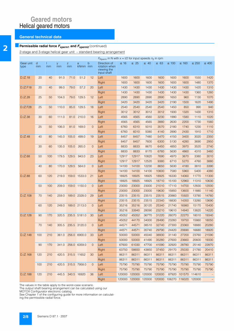
Geared motorsHelical geared motors
General technical data
2/8 Siemens D 87.1 · 2007
2 ■ Permissible radial force Fxperm1 and Fxperm2 (continued)
2-stage and 3-stage helical gear unit – standard bearing arrangement
The values in the table apply to the worst-case scenario. The output shaft bearing arrangement can be calculated using our MOTOX Configurator electronic catalog. See Chapter 1 of the configuring guide for more information on calculat-ing the permissible radial force.
FRperm in N with x = l/2 for input speeds n2 in rpm
Gear unit type
dmm
lmm
ymm
zmm
akNmm
bmm
Direction of rotation when viewing the input shaft
≤ 16 ≤ 25 ≤ 40 ≤ 63 ≤ 100 ≤ 160 ≤ 250 ≤ 400
D./Z.18 20 40 91.0 71.0 51.2 12 Left 1600 1600 1600 1600 1600 1600 1550 1420
Right 1600 1600 1600 1600 1600 1600 1480 1370
D./Z.F18 20 40 99.0 79.0 57.2 20 Left 1430 1430 1430 1430 1430 1430 1420 1310
Right 1430 1430 1430 1430 1430 1430 1360 1260
D./Z.28 25 50 104.0 79.0 129.5 12 Left 2890 2890 2890 2890 1650 960 1130 1070
Right 3420 3420 3420 3420 2190 1500 1620 1490
D./Z.F28 25 50 110.0 85.0 129.5 18 Left 2540 2540 2540 2540 1450 850 990 940
Right 3012 3012 3012 3012 1930 1320 1430 1310
D./Z.38 30 60 111.0 81.0 210.0 16 Left 4565 4565 4560 3230 1990 1580 1110 1020
Right 4565 4565 4565 3880 2630 2200 1730 1560
25 50 106.0 81.0 169.0 0 Left 6760 6310 5010 3570 2180 1740 1230 1110
Right 6760 6010 5080 4140 2890 2430 1910 1710
D./Z.48 40 80 145.0 105.0 499.0 19 Left 8457 8457 7480 5470 4150 3400 3020 2350
Right 8457 8457 7600 6300 5130 4280 3690 2950
30 60 135.0 105.0 265.0 0 Left 8833 8833 8670 6450 4850 3970 3520 2740
Right 8833 8833 8170 6760 5630 4860 4310 3460
D./Z.68 50 100 179.5 129.5 943.0 23 Left 12917 12917 10820 7690 4970 3670 3380 3010
Right 12917 12917 12520 9380 6710 5270 4760 3880
40 80 170.0 129.5 564.0 0 Left 14100 14100 12230 8650 5630 4180 3810 3390
Right 14100 14100 14100 10600 7580 5960 5400 4380
D./Z.88 60 120 219.0 159.0 1533.0 21 Left 18925 18925 18925 18925 16330 14060 11770 11300
Right 18925 18925 18925 18710 15100 12960 11310 10630
50 100 209.0 159.0 1150.0 0 Left 23000 23000 23000 21010 17110 14700 12830 12000
Right 23000 23000 23000 19630 15850 13600 11880 11140
D./Z.108 70 140 259.0 189.0 2328.0 29 Left 23515 23515 23515 23515 20860 15920 13780 14760
Right 23515 23515 23515 22340 18830 14350 13280 13690
60 120 249.0 189.0 2113.0 0 Left 35216 35216 30120 25340 21740 16980 15170 15400
Right 35216 33940 28090 23210 19610 14940 13820 14220
D./Z.128 90 170 320.5 235.5 5181.0 30 Left 45052 45052 36770 31220 26070 22270 18010 19340
Right 45052 44170 34000 28490 23260 19750 15860 18050
70 140 305.5 235.5 3120.0 0 Left 44571 44571 38510 32740 27300 23360 18880 20280
Right 44571 44571 35740 29790 24420 20690 16680 18920
D./Z.148 100 210 361.0 256.0 6900.0 33 Left 50000 50000 45040 38930 31140 27200 23760 21590
Right 50000 50000 41490 35280 27600 23660 20600 19330
90 170 341.0 256.0 6359.0 0 Left 67600 61030 47700 41090 32920 28780 25140 22870
Right 63750 58650 43850 37450 29170 25030 21780 20410
D./Z.168 120 210 420.5 315.5 11652 30 Left 86311 86311 86311 86311 86311 86311 86311 86311
Right 86311 86311 86311 86311 86311 86311 86311 86311
100 210 420.5 315.5 7958.0 0 Left 75790 75790 75790 75790 75790 75790 75790 75790
Right 75790 75790 75790 75790 75790 75790 75790 75790
D./Z.188 120 210 445.5 340.5 16920 36 Left 120000 120000 120000 120000 87920 101570 114610 –
Right 120000 120000 120000 120000 106270 116020 120000 –
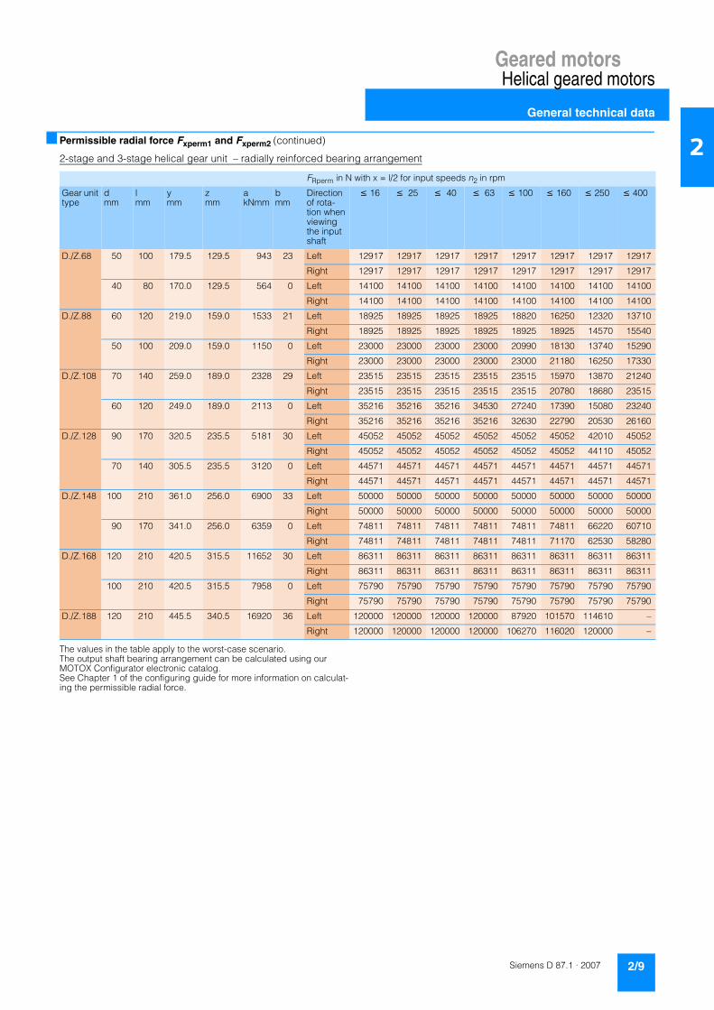
Geared motorsHelical geared motors
General technical data
2/9Siemens D 87.1 · 2007
2■ Permissible radial force Fxperm1 and Fxperm2 (continued)
2-stage and 3-stage helical gear unit – radially reinforced bearing arrangement
The values in the table apply to the worst-case scenario. The output shaft bearing arrangement can be calculated using our MOTOX Configurator electronic catalog. See Chapter 1 of the configuring guide for more information on calculat-ing the permissible radial force.
FRperm in N with x = l/2 for input speeds n2 in rpm
Gear unit type
dmm
lmm
ymm
zmm
akNmm
bmm
Direction of rota-tion when viewing the input shaft
≤ 16 ≤ 25 ≤ 40 ≤ 63 ≤ 100 ≤ 160 ≤ 250 ≤ 400
D./Z.68 50 100 179.5 129.5 943 23 Left 12917 12917 12917 12917 12917 12917 12917 12917
Right 12917 12917 12917 12917 12917 12917 12917 12917
40 80 170.0 129.5 564 0 Left 14100 14100 14100 14100 14100 14100 14100 14100
Right 14100 14100 14100 14100 14100 14100 14100 14100
D./Z.88 60 120 219.0 159.0 1533 21 Left 18925 18925 18925 18925 18820 16250 12320 13710
Right 18925 18925 18925 18925 18925 18925 14570 15540
50 100 209.0 159.0 1150 0 Left 23000 23000 23000 23000 20990 18130 13740 15290
Right 23000 23000 23000 23000 23000 21180 16250 17330
D./Z.108 70 140 259.0 189.0 2328 29 Left 23515 23515 23515 23515 23515 15970 13870 21240
Right 23515 23515 23515 23515 23515 20780 18680 23515
60 120 249.0 189.0 2113 0 Left 35216 35216 35216 34530 27240 17390 15080 23240
Right 35216 35216 35216 35216 32630 22790 20530 26160
D./Z.128 90 170 320.5 235.5 5181 30 Left 45052 45052 45052 45052 45052 45052 42010 45052
Right 45052 45052 45052 45052 45052 45052 44110 45052
70 140 305.5 235.5 3120 0 Left 44571 44571 44571 44571 44571 44571 44571 44571
Right 44571 44571 44571 44571 44571 44571 44571 44571
D./Z.148 100 210 361.0 256.0 6900 33 Left 50000 50000 50000 50000 50000 50000 50000 50000
Right 50000 50000 50000 50000 50000 50000 50000 50000
90 170 341.0 256.0 6359 0 Left 74811 74811 74811 74811 74811 74811 66220 60710
Right 74811 74811 74811 74811 74811 71170 62530 58280
D./Z.168 120 210 420.5 315.5 11652 30 Left 86311 86311 86311 86311 86311 86311 86311 86311
Right 86311 86311 86311 86311 86311 86311 86311 86311
100 210 420.5 315.5 7958 0 Left 75790 75790 75790 75790 75790 75790 75790 75790
Right 75790 75790 75790 75790 75790 75790 75790 75790
D./Z.188 120 210 445.5 340.5 16920 36 Left 120000 120000 120000 120000 87920 101570 114610 –
Right 120000 120000 120000 120000 106270 116020 120000 –

Geared motorsHelical geared motors
Geared motors up to 200 kW
2/10 Siemens D 87.1 · 2007
2 ■ Selection and ordering data
The selection tables show the most common variants and combinations. Other combinations can be selected using our MOTOX Configurator or made available on request.
At an identical power and output speed, priority is given in the selection tables to 4-pole geared motors.
At the available transmission ratios, they cover the majority of output speeds.
Due to their prevalence, 4-pole geared motors are easily avail-able, with short delivery times and at a low cost. They also fea-ture a favorable size / power ratio.
PowerPmotor
Output speed Output torque
Service factor
Gear ratio
Order number Order code
Weight
kW n2 (50 Hz) n2 (60 Hz) M2 fB itot (No. of poles)rpm rpm Nm kg
0.09 (50 Hz) D.48-LA71M80.11 (60 Hz) 3.0 3.6 285 1.6 208.77 � 2KJ1203 - 7CE13 - 77S1-Z P02 27
3.4 4.1 253 1.8 185.66 2KJ1203 - 7CE13 - 77R1-Z P02 27
D.38-LA71M83.3 4.0 262 0.84 191.75 � 2KJ1202 - 7CE13 - 77S1-Z P02 18
3.7 4.4 232 0.95 170.24 2KJ1202 - 7CE13 - 77R1-Z P02 18
4.2 5.0 204 1.10 149.26 � 2KJ1202 - 7CE13 - 77Q1-Z P02 18
D.38-LA71B64.6 5.5 186 1.2 191.75 � 2KJ1202 - 7CB13 - 77S1-Z P01 18
5.2 6.2 165 1.3 170.24 2KJ1202 - 7CB13 - 77R1-Z P01 18
5.9 7.1 145 1.5 149.26 � 2KJ1202 - 7CB13 - 77Q1-Z P01 18
6.6 7.9 130 1.7 133.57 2KJ1202 - 7CB13 - 77P1-Z P01 18
0.12 (50 Hz) D.188-D48-LA71B40.14 (60 Hz) 0.05 0.06 14482 1.4 24996 � 2KJ1236 - 7CB13 - 77H1 604
0.05 0.06 16373 1.2 28260 2KJ1236 - 7CB13 - 77J1 604
0.06 0.07 13125 1.5 22654 2KJ1236 - 7CB13 - 77G1 604
0.07 0.08 10451 1.9 18039 2KJ1236 - 7CB13 - 77E1 604
0.07 0.08 11586 1.7 19997 � 2KJ1236 - 7CB13 - 77F1 604
D.168-D48-LA71B40.05 0.06 14643 0.96 25274 2KJ1234 - 7CB13 - 77E1 460
0.05 0.06 16232 0.86 28017 � 2KJ1234 - 7CB13 - 77F1 460
0.06 0.07 13281 1.10 22923 � 2KJ1234 - 7CB13 - 77D1 460
0.07 0.08 12101 1.20 20886 2KJ1234 - 7CB13 - 77C1 460
D.168-Z48-LA71B40.08 0.10 10373 1.3 17519 2KJ1232 - 7CB13 - 77A2 459
0.09 0.11 9180 1.5 15504 � 2KJ1232 - 7CB13 - 77X1 459
0.10 0.12 8345 1.7 14094 2KJ1232 - 7CB13 - 77W1 459
0.11 0.13 7497 1.9 12661 � 2KJ1232 - 7CB13 - 77V1 459
D.148-Z38-LA71B40.09 0.11 8781 0.91 14830 2KJ1228 - 7CB13 - 77X1 283
0.10 0.12 7809 1.00 13188 2KJ1228 - 7CB13 - 77W1 283
0.12 0.14 6774 1.20 11440 2KJ1228 - 7CB13 - 77V1 283
0.13 0.16 6329 1.30 10689 2KJ1228 - 7CB13 - 77U1 283
0.14 0.17 5566 1.40 9401 2KJ1228 - 7CB13 - 77T1 283
0.16 0.19 4875 1.60 8233 2KJ1228 - 7CB13 - 77S1 283
0.18 0.22 4312 1.90 7282 2KJ1228 - 7CB13 - 77R1 283
0.20 0.24 3908 2.00 6600 2KJ1228 - 7CB13 - 77Q1 283
D.128-Z38-LA71B40.13 0.16 6229 0.82 10521 2KJ1225 - 7CB13 - 77W1 198
� Preferred transmission ratio
Shaft designs. see page 2/117 –––––––––––––––––––––––––––––––––––––––––– 1, 2 or 9 ––––––––––––––––––
Frequency and voltage, see page 8/15 ––––––––––––––––––––––––––––––––––– 1 to 9 ––––––––––––––––––––––––––––––
Gear unit housing mounting position, see page 2/116 –––––––––––––––––––––– A, F, H or R ––––––––––––––––––––––––––
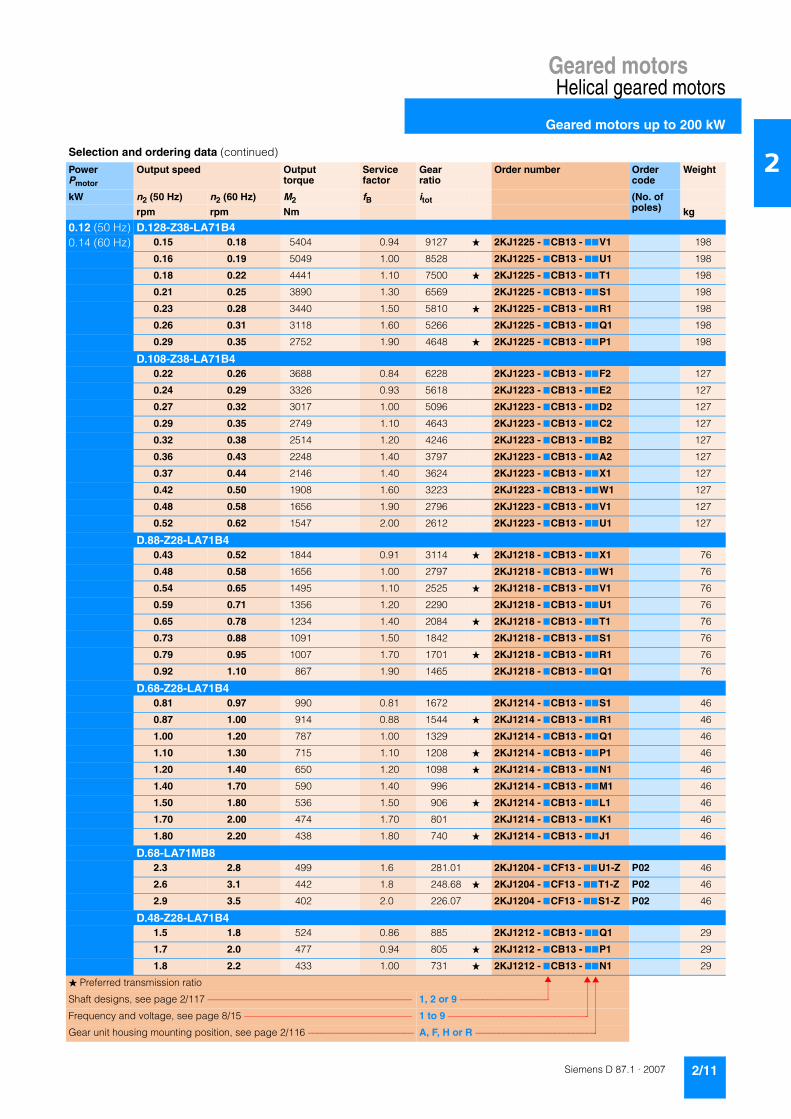
Geared motorsHelical geared motors
Geared motors up to 200 kW
2/11Siemens D 87.1 · 2007
2Selection and ordering data (continued)
PowerPmotor
Output speed Output torque
Service factor
Gear ratio
Order number Order code
Weight
kW n2 (50 Hz) n2 (60 Hz) M2 fB itot (No. of poles)rpm rpm Nm kg
0.12 (50 Hz) D.128-Z38-LA71B40.14 (60 Hz) 0.15 0.18 5404 0.94 9127 � 2KJ1225 - 7CB13 - 77V1 198
0.16 0.19 5049 1.00 8528 2KJ1225 - 7CB13 - 77U1 198
0.18 0.22 4441 1.10 7500 � 2KJ1225 - 7CB13 - 77T1 198
0.21 0.25 3890 1.30 6569 2KJ1225 - 7CB13 - 77S1 198
0.23 0.28 3440 1.50 5810 � 2KJ1225 - 7CB13 - 77R1 198
0.26 0.31 3118 1.60 5266 2KJ1225 - 7CB13 - 77Q1 198
0.29 0.35 2752 1.90 4648 � 2KJ1225 - 7CB13 - 77P1 198
D.108-Z38-LA71B40.22 0.26 3688 0.84 6228 2KJ1223 - 7CB13 - 77F2 127
0.24 0.29 3326 0.93 5618 2KJ1223 - 7CB13 - 77E2 127
0.27 0.32 3017 1.00 5096 2KJ1223 - 7CB13 - 77D2 127
0.29 0.35 2749 1.10 4643 2KJ1223 - 7CB13 - 77C2 127
0.32 0.38 2514 1.20 4246 2KJ1223 - 7CB13 - 77B2 127
0.36 0.43 2248 1.40 3797 2KJ1223 - 7CB13 - 77A2 127
0.37 0.44 2146 1.40 3624 2KJ1223 - 7CB13 - 77X1 127
0.42 0.50 1908 1.60 3223 2KJ1223 - 7CB13 - 77W1 127
0.48 0.58 1656 1.90 2796 2KJ1223 - 7CB13 - 77V1 127
0.52 0.62 1547 2.00 2612 2KJ1223 - 7CB13 - 77U1 127
D.88-Z28-LA71B40.43 0.52 1844 0.91 3114 � 2KJ1218 - 7CB13 - 77X1 76
0.48 0.58 1656 1.00 2797 2KJ1218 - 7CB13 - 77W1 76
0.54 0.65 1495 1.10 2525 � 2KJ1218 - 7CB13 - 77V1 76
0.59 0.71 1356 1.20 2290 2KJ1218 - 7CB13 - 77U1 76
0.65 0.78 1234 1.40 2084 � 2KJ1218 - 7CB13 - 77T1 76
0.73 0.88 1091 1.50 1842 2KJ1218 - 7CB13 - 77S1 76
0.79 0.95 1007 1.70 1701 � 2KJ1218 - 7CB13 - 77R1 76
0.92 1.10 867 1.90 1465 2KJ1218 - 7CB13 - 77Q1 76
D.68-Z28-LA71B40.81 0.97 990 0.81 1672 2KJ1214 - 7CB13 - 77S1 46
0.87 1.00 914 0.88 1544 � 2KJ1214 - 7CB13 - 77R1 46
1.00 1.20 787 1.00 1329 2KJ1214 - 7CB13 - 77Q1 46
1.10 1.30 715 1.10 1208 � 2KJ1214 - 7CB13 - 77P1 46
1.20 1.40 650 1.20 1098 � 2KJ1214 - 7CB13 - 77N1 46
1.40 1.70 590 1.40 996 2KJ1214 - 7CB13 - 77M1 46
1.50 1.80 536 1.50 906 � 2KJ1214 - 7CB13 - 77L1 46
1.70 2.00 474 1.70 801 2KJ1214 - 7CB13 - 77K1 46
1.80 2.20 438 1.80 740 � 2KJ1214 - 7CB13 - 77J1 46
D.68-LA71MB82.3 2.8 499 1.6 281.01 2KJ1204 - 7CF13 - 77U1-Z P02 46
2.6 3.1 442 1.8 248.68 � 2KJ1204 - 7CF13 - 77T1-Z P02 46
2.9 3.5 402 2.0 226.07 2KJ1204 - 7CF13 - 77S1-Z P02 46
D.48-Z28-LA71B41.5 1.8 524 0.86 885 2KJ1212 - 7CB13 - 77Q1 29
1.7 2.0 477 0.94 805 � 2KJ1212 - 7CB13 - 77P1 29
1.8 2.2 433 1.00 731 � 2KJ1212 - 7CB13 - 77N1 29
� Preferred transmission ratio
Shaft designs, see page 2/117 –––––––––––––––––––––––––––––––––––––––––– 1, 2 or 9 –––––––––––––––––––
Frequency and voltage, see page 8/15 ––––––––––––––––––––––––––––––––––– 1 to 9 ––––––––––––––––––––––––––––––
Gear unit housing mounting position, see page 2/116 –––––––––––––––––––––– A, F, H or R ––––––––––––––––––––––––––

Geared motorsHelical geared motors
Geared motors up to 200 kW
2/12 Siemens D 87.1 · 2007
2
0.12 (50 Hz) D.48-Z28-LA71B40.14 (60 Hz) 2.0 2.4 393 1.1 663 2KJ1212 - 7CB13 - 77M1 29
2.2 2.6 357 1.3 603 � 2KJ1212 - 7CB13 - 77L1 29
2.5 3.0 316 1.4 534 2KJ1212 - 7CB13 - 77K1 29
2.7 3.2 292 1.5 493 � 2KJ1212 - 7CB13 - 77J1 29
D.48-LA71MB83.1 3.7 371 1.2 208.77 � 2KJ1203 - 7CF13 - 77S1-Z P02 27
3.5 4.2 330 1.4 185.66 2KJ1203 - 7CF13 - 77R1-Z P02 27
D.48-LA71C64.1 4.9 278 1.6 208.77 � 2KJ1203 - 7CC13 - 77S1-Z P01 27
4.6 5.5 247 1.8 185.66 2KJ1203 - 7CC13 - 77R1-Z P01 27
5.3 6.4 215 2.1 161.05 � 2KJ1203 - 7CC13 - 77Q1-Z P01 27
D.38-LA71MB84.3 5.2 265 0.83 149.26 � 2KJ1202 - 7CF13 - 77Q1-Z P02 18
D.38-LA71C64.5 5.4 256 0.86 191.75 � 2KJ1202 - 7CC13 - 77S1-Z P01 18
5.1 6.1 227 0.97 170.24 2KJ1202 - 7CC13 - 77R1-Z P01 18
5.8 7.0 199 1.10 149.26 � 2KJ1202 - 7CC13 - 77Q1-Z P01 18
6.4 7.7 178 1.20 133.57 2KJ1202 - 7CC13 - 77P1-Z P01 18
D.38-LA71B47.0 8.4 163 1.4 191.75 � 2KJ1202 - 7CB13 - 77S1 18
7.9 9.5 145 1.5 170.24 2KJ1202 - 7CB13 - 77R1 18
9.0 10.8 127 1.7 149.26 � 2KJ1202 - 7CB13 - 77Q1 18
10.1 12.1 113 1.9 133.57 2KJ1202 - 7CB13 - 77P1 18
11.4 13.7 101 2.2 118.55 � 2KJ1202 - 7CB13 - 77N1 18
D.28-LA71B47.6 9.1 152 0.92 178.66 2KJ1201 - 7CB13 - 77L1 10
8.2 9.8 140 1.00 164.48 � 2KJ1201 - 7CB13 - 77K1 10
9.0 10.8 127 1.10 149.53 2KJ1201 - 7CB13 - 77J1 10
10.2 12.2 112 1.20 132.35 � 2KJ1201 - 7CB13 - 77H1 10
12.2 14.6 94 1.50 110.86 2KJ1201 - 7CB13 - 77G1 10
14.3 17.2 80 1.70 94.52 � 2KJ1201 - 7CB13 - 77F1 10
16.8 20.0 68 2.10 80.34 � 2KJ1201 - 7CB13 - 77E1 10
19.3 23.0 59 2.40 69.82 2KJ1201 - 7CB13 - 77D1 10
22.0 26.0 52 2.70 60.77 � 2KJ1201 - 7CB13 - 77C1 10
Z.28-LA71B426.0 31.0 44 3.2 51.35 2KJ1101 - 7CB13 - 77C2 10
31.0 37.0 37 3.8 43.30 � 2KJ1101 - 7CB13 - 77B2 10
35.0 42.0 33 4.3 38.45 2KJ1101 - 7CB13 - 77A2 10
40.0 48.0 29 4.9 33.71 � 2KJ1101 - 7CB13 - 77X1 10
45.0 54.0 26 5.5 30.16 2KJ1101 - 7CB13 - 77W1 10
50.0 60.0 23 6.2 26.77 � 2KJ1101 - 7CB13 - 77V1 10
58.0 70.0 20 7.0 23.46 2KJ1101 - 7CB13 - 77U1 10
65.0 78.0 18 8.0 20.63 � 2KJ1101 - 7CB13 - 77T1 10
72.0 86.0 16 8.9 18.63 2KJ1101 - 7CB13 - 77S1 10
Selection and ordering data (continued)
PowerPmotor
Output speed Output torque
Service factor
Gear ratio
Order number Order code
Weight
kW n2 (50 Hz) n2 (60 Hz) M2 fB itot (No. of poles)rpm rpm Nm kg
� Preferred transmission ratio
Shaft designs, see page 2/117 –––––––––––––––––––––––––––––––––––––––––– 1, 2 or 9 –––––––––––––––––––
Frequency and voltage, see page 8/15 ––––––––––––––––––––––––––––––––––– 1 to 9 ––––––––––––––––––––––––––––––
Gear unit housing mounting position, see page 2/116 –––––––––––––––––––––– A, F, H or R ––––––––––––––––––––––––––

Geared motorsHelical geared motors
Geared motors up to 200 kW
2/13Siemens D 87.1 · 2007
2
0.12 (50 Hz) Z.28-LA71B40.14 (60 Hz) 83 100 14 10.2 16.24 � 2KJ1101 - 7CB13 - 77R1 10
93 112 12 11.3 14.58 2KJ1101 - 7CB13 - 77Q1 10
103 124 11 12.5 13.17 � 2KJ1101 - 7CB13 - 77P1 10
113 136 10 13.8 11.94 2KJ1101 - 7CB13 - 77N1 10
D.18-LA71B410.9 13.1 106 0.85 124.29 2KJ1200 - 7CB13 - 77K1 9
12.3 14.8 93 0.96 110.01 � 2KJ1200 - 7CB13 - 77J1 9
14.7 17.6 78 1.20 92.14 2KJ1200 - 7CB13 - 77H1 9
17.2 21.0 67 1.30 78.56 � 2KJ1200 - 7CB13 - 77G1 9
20.0 24.0 57 1.60 66.78 � 2KJ1200 - 7CB13 - 77F1 9
23.0 28.0 49 1.80 58.03 2KJ1200 - 7CB13 - 77E1 9
27.0 32.0 43 2.10 50.51 � 2KJ1200 - 7CB13 - 77D1 9
Z.18-LA71B431 37 37.0 2.5 43.15 2KJ1100 - 7CB13 - 77U1 9
36 43 32.0 2.8 37.23 � 2KJ1100 - 7CB13 - 77T1 9
42 50 27.0 3.3 31.98 2KJ1100 - 7CB13 - 77S1 9
46 55 25.0 3.6 29.45 � 2KJ1100 - 7CB13 - 77R1 9
50 60 23.0 4.0 26.77 2KJ1100 - 7CB13 - 77Q1 9
57 68 20.0 4.5 23.69 � 2KJ1100 - 7CB13 - 77P1 9
68 82 17.0 5.3 19.85 2KJ1100 - 7CB13 - 77N1 9
80 96 14.0 6.3 16.92 � 2KJ1100 - 7CB13 - 77M1 9
94 113 12.0 7.4 14.38 � 2KJ1100 - 7CB13 - 77L1 9
108 130 11.0 8.5 12.50 2KJ1100 - 7CB13 - 77K1 9
124 149 9.2 9.4 10.88 � 2KJ1100 - 7CB13 - 77J1 9
138 166 8.3 10.0 9.81 2KJ1100 - 7CB13 - 77H1 9
156 187 7.4 10.9 8.66 2KJ1100 - 7CB13 - 77G1 9
182 218 6.3 8.7 7.42 � 2KJ1100 - 7CB13 - 77F1 9
209 251 5.5 9.7 6.45 2KJ1100 - 7CB13 - 77E1 9
241 289 4.8 10.7 5.61 � 2KJ1100 - 7CB13 - 77D1 9
267 320 4.3 11.4 5.06 2KJ1100 - 7CB13 - 77C1 9
302 362 3.8 12.9 4.47 2KJ1100 - 7CB13 - 77B1 9
E.38-LA71B4145 174 7.9 4 9.33 � 2KJ1001 - 7CB13 - 77S1 13
0.18 (50 Hz) D.188-D48-LA71C40.22 (60 Hz) 0.05 0.06 24136 0.83 24996 � 2KJ1236 - 7CC13 - 77H1 604
0.06 0.07 21875 0.91 22654 2KJ1236 - 7CC13 - 77G1 604
0.07 0.08 17419 1.10 18039 2KJ1236 - 7CC13 - 77E1 604
0.07 0.08 19309 1.00 19997 � 2KJ1236 - 7CC13 - 77F1 604
0.08 0.10 15798 1.30 16361 � 2KJ1236 - 7CC13 - 77D1 604
0.09 0.11 14394 1.40 14907 2KJ1236 - 7CC13 - 77C1 604
D.188-Z48-LA71C40.11 0.13 12339 1.6 12504 2KJ1235 - 7CC13 - 77X1 603
0.12 0.14 10920 1.8 11066 � 2KJ1235 - 7CC13 - 77W1 603
Selection and ordering data (continued)
PowerPmotor
Output speed Output torque
Service factor
Gear ratio
Order number Order code
Weight
kW n2 (50 Hz) n2 (60 Hz) M2 fB itot (No. of poles)rpm rpm Nm kg
� Preferred transmission ratio
Shaft designs, see page 2/117 –––––––––––––––––––––––––––––––––––––––––– 1, 2 or 9 –––––––––––––––––––
Frequency and voltage, see page 8/15 ––––––––––––––––––––––––––––––––––– 1 to 9 ––––––––––––––––––––––––––––––
Gear unit housing mounting position, see page 2/116 –––––––––––––––––––––– A, F, H or R ––––––––––––––––––––––––––

Geared motorsHelical geared motors
Geared motors up to 200 kW
2/14 Siemens D 87.1 · 2007
2
0.18 (50 Hz) D.168-Z48-LA71C40.22 (60 Hz) 0.08 0.10 17288 0.81 17519 2KJ1232 - 7CC13 - 77A2 459
0.09 0.11 15300 0.92 15504 � 2KJ1232 - 7CC13 - 77X1 459
0.10 0.12 13908 1.00 14094 2KJ1232 - 7CC13 - 77W1 459
0.11 0.13 12494 1.10 12661 � 2KJ1232 - 7CC13 - 77V1 459
0.12 0.14 10710 1.30 10853 2KJ1232 - 7CC13 - 77U1 459
0.14 0.17 9690 1.40 9819 � 2KJ1232 - 7CC13 - 77T1 459
0.15 0.18 8945 1.60 9064 2KJ1232 - 7CC13 - 77S1 459
0.17 0.20 7777 1.80 7881 � 2KJ1232 - 7CC13 - 77R1 459
0.19 0.23 7062 2.00 7156 2KJ1232 - 7CC13 - 77Q1 459
D.148-Z38-LA71C40.14 0.17 9277 0.86 9401 2KJ1228 - 7CC13 - 77T1 283
0.16 0.19 8125 0.98 8233 2KJ1228 - 7CC13 - 77S1 283
0.18 0.22 7186 1.10 7282 2KJ1228 - 7CC13 - 77R1 283
0.20 0.24 6513 1.20 6600 2KJ1228 - 7CC13 - 77Q1 283
0.23 0.28 5749 1.40 5826 2KJ1228 - 7CC13 - 77P1 283
0.26 0.31 5187 1.50 5256 2KJ1228 - 7CC13 - 77N1 283
0.28 0.34 4704 1.70 4767 2KJ1228 - 7CC13 - 77M1 283
0.31 0.37 4286 1.90 4343 2KJ1228 - 7CC13 - 77L1 283
0.34 0.41 3920 2.00 3972 2KJ1228 - 7CC13 - 77K1 283
D.128-Z38-LA71C40.23 0.28 5734 0.89 5810 � 2KJ1225 - 7CC13 - 77R1 198
0.26 0.31 5197 0.98 5266 2KJ1225 - 7CC13 - 77Q1 198
0.29 0.35 4587 1.10 4648 � 2KJ1225 - 7CC13 - 77P1 198
0.32 0.38 4138 1.20 4193 2KJ1225 - 7CC13 - 77N1 198
0.35 0.42 3753 1.40 3803 � 2KJ1225 - 7CC13 - 77M1 198
0.39 0.47 3419 1.50 3465 2KJ1225 - 7CC13 - 77L1 198
0.43 0.52 3127 1.60 3169 � 2KJ1225 - 7CC13 - 77K1 198
0.48 0.58 2797 1.80 2834 2KJ1225 - 7CC13 - 77J1 198
0.52 0.62 2568 2.00 2602 � 2KJ1225 - 7CC13 - 77H1 198
D.108-Z38-LA71C40.36 0.43 3747 0.83 3797 2KJ1223 - 7CC13 - 77A2 127
0.37 0.44 3576 0.87 3624 2KJ1223 - 7CC13 - 77X1 127
0.42 0.50 3181 0.97 3223 2KJ1223 - 7CC13 - 77W1 127
0.48 0.58 2759 1.10 2796 2KJ1223 - 7CC13 - 77V1 127
0.52 0.62 2578 1.20 2612 2KJ1223 - 7CC13 - 77U1 127
0.59 0.71 2267 1.40 2297 2KJ1223 - 7CC13 - 77T1 127
0.67 0.80 1986 1.60 2012 2KJ1223 - 7CC13 - 77S1 127
0.76 0.91 1757 1.80 1780 2KJ1223 - 7CC13 - 77R1 127
0.84 1.00 1592 1.90 1613 2KJ1223 - 7CC13 - 77Q1 127
D.88-Z28-LA71C40.65 0.78 2057 0.82 2084 � 2KJ1218 - 7CC13 - 77T1 76
0.73 0.88 1818 0.92 1842 2KJ1218 - 7CC13 - 77S1 76
0.79 0.95 1679 1.00 1701 � 2KJ1218 - 7CC13 - 77R1 76
0.92 1.10 1446 1.20 1465 2KJ1218 - 7CC13 - 77Q1 76
1.00 1.20 1313 1.30 1331 � 2KJ1218 - 7CC13 - 77P1 76
Selection and ordering data (continued)
PowerPmotor
Output speed Output torque
Service factor
Gear ratio
Order number Order code
Weight
kW n2 (50 Hz) n2 (60 Hz) M2 fB itot (No. of poles)rpm rpm Nm kg
� Preferred transmission ratio
Shaft designs, see page 2/117 –––––––––––––––––––––––––––––––––––––––––– 1, 2 or 9 –––––––––––––––––––
Frequency and voltage, see page 8/15 ––––––––––––––––––––––––––––––––––– 1 to 9 ––––––––––––––––––––––––––––––
Gear unit housing mounting position, see page 2/116 –––––––––––––––––––––– A, F, H or R ––––––––––––––––––––––––––

Geared motorsHelical geared motors
Geared motors up to 200 kW
2/15Siemens D 87.1 · 2007
2
0.18 (50 Hz) D.88-Z28-LA71C40.22 (60 Hz) 1.1 1.3 1194 1.4 1210 � 2KJ1218 - 7CC13 - 77N1 76
1.2 1.4 1083 1.6 1097 2KJ1218 - 7CC13 - 77M1 76
1.4 1.7 986 1.7 999 � 2KJ1218 - 7CC13 - 77L1 76
1.5 1.8 871 1.9 883 2KJ1218 - 7CC13 - 77K1 76
D.68-Z28-LA71C41.4 1.7 983 0.81 996 2KJ1214 - 7CC13 - 77M1 46
1.5 1.8 894 0.89 906 � 2KJ1214 - 7CC13 - 77L1 46
1.7 2.0 790 1.00 801 2KJ1214 - 7CC13 - 77K1 46
1.8 2.2 730 1.10 740 � 2KJ1214 - 7CC13 - 77J1 46
2.1 2.5 629 1.30 637 2KJ1214 - 7CC13 - 77H1 46
2.2 2.6 599 1.30 607 � 2KJ1214 - 7CC13 - 77G1 46
D.68-LA80S82.4 2.9 716 1.1 281.01 2KJ1204 - 7DB13 - 77U1-Z P02 50
2.7 3.2 633 1.3 248.68 � 2KJ1204 - 7DB13 - 77T1-Z P02 50
D.68-LA71S63.0 3.6 579 1.4 281.01 2KJ1204 - 7CD13 - 77U1-Z P01 46
3.4 4.1 512 1.6 248.68 � 2KJ1204 - 7CD13 - 77T1-Z P01 46
3.7 4.4 465 1.7 226.07 2KJ1204 - 7CD13 - 77S1-Z P01 46
4.1 4.9 418 1.9 203.09 � 2KJ1204 - 7CD13 - 77R1-Z P01 46
D.48-Z28-LA71C42.5 3.0 527 0.85 534.00 2KJ1212 - 7CC13 - 77K1 29
2.7 3.2 487 0.92 493.00 � 2KJ1212 - 7CC13 - 77J1 29
D.48-LA80S83.2 3.8 532 0.85 208.77 � 2KJ1203 - 7DB13 - 77S1-Z P02 31
3.6 4.3 473 0.95 185.66 2KJ1203 - 7DB13 - 77R1-Z P02 31
D.48-LA71S64.0 4.8 430 1.0 208.77 � 2KJ1203 - 7CD13 - 77S1-Z P01 27
4.5 5.4 382 1.2 185.66 2KJ1203 - 7CD13 - 77R1-Z P01 27
5.2 6.2 332 1.4 161.05 � 2KJ1203 - 7CD13 - 77Q1-Z P01 27
5.5 6.6 310 1.5 150.48 2KJ1203 - 7CD13 - 77P1-Z P01 27
6.3 7.6 272 1.7 132.34 � 2KJ1203 - 7CD13 - 77N1-Z P01 27
D.48-LA71C46.5 7.8 266 1.7 208.77 � 2KJ1203 - 7CC13 - 77S1 27
7.3 8.8 236 1.9 185.66 2KJ1203 - 7CC13 - 77R1 27
D.38-LA71S66.3 7.6 275 0.8 133.57 2KJ1202 - 7CD13 - 77P1-Z P01 18
D.38-LA71C47.0 8.4 244 0.9 191.75 � 2KJ1202 - 7CC13 - 77S1 18
7.9 9.5 217 1.0 170.24 2KJ1202 - 7CC13 - 77R1 18
9.0 10.8 190 1.2 149.26 � 2KJ1202 - 7CC13 - 77Q1 18
10.1 12.1 170 1.3 133.57 2KJ1202 - 7CC13 - 77P1 18
11.4 13.7 151 1.5 118.55 � 2KJ1202 - 7CC13 - 77N1 18
13.0 15.6 132 1.7 103.89 2KJ1202 - 7CC13 - 77M1 18
14.8 17.8 116 1.9 91.34 � 2KJ1202 - 7CC13 - 77L1 18
16.4 19.7 105 2.1 82.52 2KJ1202 - 7CC13 - 77K1 18
Selection and ordering data (continued)
PowerPmotor
Output speed Output torque
Service factor
Gear ratio
Order number Order code
Weight
kW n2 (50 Hz) n2 (60 Hz) M2 fB itot (No. of poles)rpm rpm Nm kg
� Preferred transmission ratio
Shaft designs, see page 2/117 –––––––––––––––––––––––––––––––––––––––––– 1, 2 or 9 –––––––––––––––––––
Frequency and voltage, see page 8/15 ––––––––––––––––––––––––––––––––––– 1 to 9 ––––––––––––––––––––––––––––––
Gear unit housing mounting position, see page 2/116 –––––––––––––––––––––– A, F, H or R ––––––––––––––––––––––––––

Geared motorsHelical geared motors
Geared motors up to 200 kW
2/16 Siemens D 87.1 · 2007
2
0.18 (50 Hz) D.28-LA71C40.22 (60 Hz) 10.2 12.2 169 0.83 132.35 � 2KJ1201 - 7CC13 - 77H1 10
12.2 14.6 141 0.99 110.86 2KJ1201 - 7CC13 - 77G1 10
14.3 17.2 120 1.20 94.52 � 2KJ1201 - 7CC13 - 77F1 10
16.8 20.0 102 1.40 80.34 � 2KJ1201 - 7CC13 - 77E1 10
19.3 23.0 89 1.60 69.82 2KJ1201 - 7CC13 - 77D1 10
22.0 26.0 77 1.80 60.77 � 2KJ1201 - 7CC13 - 77C1 10
Z.28-LA71C426 31 65.0 2.1 51.35 2KJ1101 - 7CC13 - 77C2 10
31 37 55.0 2.5 43.30 � 2KJ1101 - 7CC13 - 77B2 10
35 42 49.0 2.9 38.45 2KJ1101 - 7CC13 - 77A2 10
40 48 43.0 3.3 33.71 � 2KJ1101 - 7CC13 - 77X1 10
45 54 38.0 3.6 30.16 2KJ1101 - 7CC13 - 77W1 10
50 60 34.0 4.1 26.77 � 2KJ1101 - 7CC13 - 77V1 10
58 70 30.0 4.7 23.46 2KJ1101 - 7CC13 - 77U1 10
65 78 26.0 5.3 20.63 � 2KJ1101 - 7CC13 - 77T1 10
72 86 24.0 5.9 18.63 2KJ1101 - 7CC13 - 77S1 10
83 100 21.0 6.8 16.24 � 2KJ1101 - 7CC13 - 77R1 10
93 112 19.0 7.5 14.58 2KJ1101 - 7CC13 - 77Q1 10
103 124 17.0 8.3 13.17 � 2KJ1101 - 7CC13 - 77P1 10
113 136 15.0 9.2 11.94 2KJ1101 - 7CC13 - 77N1 10
124 149 14.0 10.1 10.87 � 2KJ1101 - 7CC13 - 77M1 10
140 168 12.0 11.4 9.61 2KJ1101 - 7CC13 - 77L1 10
152 182 11.0 12.4 8.87 � 2KJ1101 - 7CC13 - 77K1 10
177 212 9.7 14.0 7.64 2KJ1101 - 7CC13 - 77J1 10
195 234 8.8 14.9 6.94 � 2KJ1101 - 7CC13 - 77H1 10
214 257 8.0 11.8 6.31 � 2KJ1101 - 7CC13 - 77G1 10
236 283 7.3 12.8 5.72 2KJ1101 - 7CC13 - 77F1 10
259 311 6.6 13.9 5.21 � 2KJ1101 - 7CC13 - 77E1 10
293 352 5.9 15.0 4.60 2KJ1101 - 7CC13 - 77D1 10
D.18-LA71C417.2 21 100 0.9 78.56 � 2KJ1200 - 7CC13 - 77G1 9
20.0 24 85 1.1 66.78 � 2KJ1200 - 7CC13 - 77F1 9
23.0 28 74 1.2 58.03 2KJ1200 - 7CC13 - 77E1 9
27.0 32 64 1.4 50.51 � 2KJ1200 - 7CC13 - 77D1 9
Z.18-LA71C431 37 55 1.6 43.15 2KJ1100 - 7CC13 - 77U1 9
36 43 47 1.9 37.23 � 2KJ1100 - 7CC13 - 77T1 9
42 50 41 2.2 31.98 2KJ1100 - 7CC13 - 77S1 9
46 55 38 2.4 29.45 � 2KJ1100 - 7CC13 - 77R1 9
50 60 34 2.6 26.77 2KJ1100 - 7CC13 - 77Q1 9
57 68 30 3.0 23.69 � 2KJ1100 - 7CC13 - 77P1 9
68 82 25 3.6 19.85 2KJ1100 - 7CC13 - 77N1 9
80 96 22 4.2 16.92 � 2KJ1100 - 7CC13 - 77M1 9
94 113 18 4.9 14.38 � 2KJ1100 - 7CC13 - 77L1 9
Selection and ordering data (continued)
PowerPmotor
Output speed Output torque
Service factor
Gear ratio
Order number Order code
Weight
kW n2 (50 Hz) n2 (60 Hz) M2 fB itot (No. of poles)rpm rpm Nm kg
� Preferred transmission ratio
Shaft designs, see page 2/117 –––––––––––––––––––––––––––––––––––––––––– 1, 2 or 9 –––––––––––––––––––
Frequency and voltage, see page 8/15 ––––––––––––––––––––––––––––––––––– 1 to 9 ––––––––––––––––––––––––––––––
Gear unit housing mounting position, see page 2/116 –––––––––––––––––––––– A, F, H or R ––––––––––––––––––––––––––

Geared motorsHelical geared motors
Geared motors up to 200 kW
2/17Siemens D 87.1 · 2007
2
0.18 (50 Hz) Z.18-LA71C40.22 (60 Hz) 108 130 16.0 5.7 12.50 2KJ1100 - 7CC13 - 77K1 9
124 149 14.0 6.3 10.88 � 2KJ1100 - 7CC13 - 77J1 9
138 166 12.0 6.6 9.81 2KJ1100 - 7CC13 - 77H1 9
156 187 11.0 7.3 8.66 2KJ1100 - 7CC13 - 77G1 9
182 218 9.4 5.8 7.42 � 2KJ1100 - 7CC13 - 77F1 9
209 251 8.2 6.5 6.45 2KJ1100 - 7CC13 - 77E1 9
241 289 7.1 7.1 5.61 � 2KJ1100 - 7CC13 - 77D1 9
267 320 6.4 7.6 5.06 2KJ1100 - 7CC13 - 77C1 9
302 362 5.7 8.6 4.47 2KJ1100 - 7CC13 - 77B1 9
377 452 4.6 10.1 3.58 � 2KJ1100 - 7CC13 - 77A1 9
E.38-LA71C4145 174 12.0 2.7 9.33 � 2KJ1001 - 7CC13 - 77S1 13
163 196 11.0 3.0 8.30 2KJ1001 - 7CC13 - 77R1 13
188 226 9.2 4.1 7.20 � 2KJ1001 - 7CC13 - 77Q1 13
0.25 (50 Hz) D.188-D48-LA71S40.30 (60 Hz) 0.08 0.10 23171 0.86 16361 � 2KJ1236 - 7CD13 - 77D1 604
0.09 0.11 21112 0.95 14907 2KJ1236 - 7CD13 - 77C1 604
D.188-Z48-LA71S40.11 0.13 18098 1.1 12504 2KJ1235 - 7CD13 - 77X1 603
0.12 0.14 16016 1.2 11066 � 2KJ1235 - 7CD13 - 77W1 603
0.15 0.18 13080 1.5 9037 � 2KJ1235 - 7CD13 - 77V1 603
0.17 0.20 11211 1.8 7746 2KJ1235 - 7CD13 - 77U1 603
0.19 0.23 10143 2.0 7008 � 2KJ1235 - 7CD13 - 77T1 603
D.168-Z48-LA71S40.12 0.14 15708 0.89 10853 2KJ1232 - 7CD13 - 77U1 459
0.14 0.17 14212 0.99 9819 � 2KJ1232 - 7CD13 - 77T1 459
0.15 0.18 13119 1.10 9064 2KJ1232 - 7CD13 - 77S1 459
0.17 0.20 11407 1.20 7881 � 2KJ1232 - 7CD13 - 77R1 459
0.19 0.23 10357 1.40 7156 2KJ1232 - 7CD13 - 77Q1 459
0.21 0.25 9457 1.50 6534 � 2KJ1232 - 7CD13 - 77P1 459
0.23 0.28 8677 1.60 5995 2KJ1232 - 7CD13 - 77N1 459
0.24 0.29 7994 1.80 5523 � 2KJ1232 - 7CD13 - 77M1 459
0.27 0.32 7260 1.90 5016 2KJ1232 - 7CD13 - 77L1 459
D.148-Z38-LA71S40.20 0.24 9553 0.84 6600 2KJ1228 - 7CD13 - 77Q1 283
0.23 0.28 8432 0.95 5826 2KJ1228 - 7CD13 - 77P1 283
0.26 0.31 7607 1.10 5256 2KJ1228 - 7CD13 - 77N1 283
0.28 0.34 6900 1.20 4767 2KJ1228 - 7CD13 - 77M1 283
0.31 0.37 6286 1.30 4343 2KJ1228 - 7CD13 - 77L1 283
0.34 0.41 5749 1.40 3972 2KJ1228 - 7CD13 - 77K1 283
0.38 0.46 5141 1.60 3552 2KJ1228 - 7CD13 - 77J1 283
0.41 0.49 4720 1.70 3261 2KJ1228 - 7CD13 - 77H1 283
0.46 0.55 4254 1.90 2939 2KJ1228 - 7CD13 - 77G1 283
Selection and ordering data (continued)
PowerPmotor
Output speed Output torque
Service factor
Gear ratio
Order number Order code
Weight
kW n2 (50 Hz) n2 (60 Hz) M2 fB itot (No. of poles)rpm rpm Nm kg
� Preferred transmission ratio
Shaft designs, see page 2/117 –––––––––––––––––––––––––––––––––––––––––– 1, 2 or 9 –––––––––––––––––––
Frequency and voltage, see page 8/15 ––––––––––––––––––––––––––––––––––– 1 to 9 ––––––––––––––––––––––––––––––
Gear unit housing mounting position, see page 2/116 –––––––––––––––––––––– A, F, H or R ––––––––––––––––––––––––––
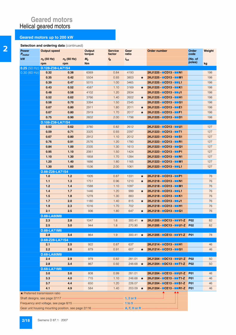
Geared motorsHelical geared motors
Geared motors up to 200 kW
2/18 Siemens D 87.1 · 2007
2
0.25 (50 Hz) D.128-Z38-LA71S40.30 (60 Hz) 0.32 0.38 6069 0.84 4193 2KJ1225 - 7CD13 - 77N1 198
0.35 0.42 5504 0.93 3803 � 2KJ1225 - 7CD13 - 77M1 198
0.39 0.47 5015 1.00 3465 2KJ1225 - 7CD13 - 77L1 198
0.43 0.52 4587 1.10 3169 � 2KJ1225 - 7CD13 - 77K1 198
0.48 0.58 4102 1.20 2834 2KJ1225 - 7CD13 - 77J1 198
0.52 0.62 3766 1.40 2602 � 2KJ1225 - 7CD13 - 77H1 198
0.58 0.70 3394 1.50 2345 2KJ1225 - 7CD13 - 77G1 198
0.67 0.80 2911 1.80 2011 � 2KJ1225 - 7CD13 - 77E1 198
0.67 0.80 2919 1.70 2017 � 2KJ1225 - 7CD13 - 77F1 198
0.75 0.90 2602 2.00 1798 2KJ1225 - 7CD13 - 77D1 198
D.108-Z38-LA71S40.52 0.62 3780 0.82 2612 2KJ1223 - 7CD13 - 77U1 127
0.59 0.71 3325 0.93 2297 2KJ1223 - 7CD13 - 77T1 127
0.67 0.80 2912 1.10 2012 2KJ1223 - 7CD13 - 77S1 127
0.76 0.91 2576 1.20 1780 2KJ1223 - 7CD13 - 77R1 127
0.84 1.00 2335 1.30 1613 2KJ1223 - 7CD13 - 77Q1 127
0.95 1.10 2061 1.50 1424 2KJ1223 - 7CD13 - 77P1 127
1.10 1.30 1858 1.70 1284 2KJ1223 - 7CD13 - 77N1 127
1.20 1.40 1686 1.80 1165 2KJ1223 - 7CD13 - 77M1 127
1.30 1.60 1536 2.00 1061 2KJ1223 - 7CD13 - 77L1 127
D.88-Z28-LA71S41.0 1.2 1926 0.87 1331 � 2KJ1218 - 7CD13 - 77P1 76
1.1 1.3 1751 0.96 1210 � 2KJ1218 - 7CD13 - 77N1 76
1.2 1.4 1588 1.10 1097 2KJ1218 - 7CD13 - 77M1 76
1.4 1.7 1446 1.20 999 � 2KJ1218 - 7CD13 - 77L1 76
1.5 1.8 1278 1.30 883 2KJ1218 - 7CD13 - 77K1 76
1.7 2.0 1180 1.40 815 � 2KJ1218 - 7CD13 - 77J1 76
1.9 2.3 1016 1.70 702 2KJ1218 - 7CD13 - 77H1 76
2.1 2.5 936 1.80 647 � 2KJ1218 - 7CD13 - 77G1 76
D.88-LA80M82.3 2.8 1047 1.6 300.41 � 2KJ1205 - 7DC13 - 77V1-Z P02 82
2.5 3.0 944 1.8 270.90 2KJ1205 - 7DC13 - 77U1-Z P02 82
D.88-LA71M62.8 3.4 864 1.9 300.41 � 2KJ1205 - 7CE13 - 77V1-Z P01 78
D.68-Z28-LA71S42.1 2.5 922 0.87 637 2KJ1214 - 7CD13 - 77H1 46
2.2 2.6 879 0.91 607 � 2KJ1214 - 7CD13 - 77G1 46
D.68-LA80M82.4 2.9 979 0.82 281.01 2KJ1204 - 7DC13 - 77U1-Z P02 50
2.8 3.4 867 0.92 248.68 � 2KJ1204 - 7DC13 - 77T1-Z P02 50
D.68-LA71M63.0 3.6 808 0.99 281.01 2KJ1204 - 7CE13 - 77U1-Z P01 46
3.3 4.0 715 1.10 248.68 � 2KJ1204 - 7CE13 - 77T1-Z P01 46
3.7 4.4 650 1.20 226.07 2KJ1204 - 7CE13 - 77S1-Z P01 46
4.1 4.9 584 1.40 203.09 � 2KJ1204 - 7CE13 - 77R1-Z P01 46
Selection and ordering data (continued)
PowerPmotor
Output speed Output torque
Service factor
Gear ratio
Order number Order code
Weight
kW n2 (50 Hz) n2 (60 Hz) M2 fB itot (No. of poles)rpm rpm Nm kg
� Preferred transmission ratio
Shaft designs, see page 2/117 –––––––––––––––––––––––––––––––––––––––––– 1, 2 or 9 –––––––––––––––––––
Frequency and voltage, see page 8/15 ––––––––––––––––––––––––––––––––––– 1 to 9 ––––––––––––––––––––––––––––––
Gear unit housing mounting position, see page 2/116 –––––––––––––––––––––– A, F, H or R ––––––––––––––––––––––––––

Geared motorsHelical geared motors
Geared motors up to 200 kW
2/19Siemens D 87.1 · 2007
2
0.25 (50 Hz) D.68-LA71S40.30 (60 Hz) 4.8 5.8 497 1.6 281.01 2KJ1204 - 7CD13 - 77U1 46
5.4 6.5 440 1.8 248.68 � 2KJ1204 - 7CD13 - 77T1 46
6.0 7.2 400 2.0 226.07 2KJ1204 - 7CD13 - 77S1 46
D.48-LA71M64.5 5.4 534 0.84 185.66 2KJ1203 - 7CE13 - 77R1-Z P01 27
5.2 6.2 463 0.97 161.05 � 2KJ1203 - 7CE13 - 77Q1-Z P01 27
5.5 6.6 433 1.00 150.48 2KJ1203 - 7CE13 - 77P1-Z P01 27
6.3 7.6 381 1.20 132.34 � 2KJ1203 - 7CE13 - 77N1-Z P01 27
D.48-LA71S46.5 7.8 369 1.2 208.77 � 2KJ1203 - 7CD13 - 77S1 27
7.3 8.8 328 1.4 185.66 2KJ1203 - 7CD13 - 77R1 27
8.4 10.1 285 1.6 161.05 � 2KJ1203 - 7CD13 - 77Q1 27
9.0 10.8 266 1.7 150.48 2KJ1203 - 7CD13 - 77P1 27
10.2 12.2 234 1.9 132.34 � 2KJ1203 - 7CD13 - 77N1 27
11.6 13.9 205 2.2 115.91 2KJ1203 - 7CD13 - 77M1 27
D.38-LA71S49.0 10.8 264 0.83 149.26 � 2KJ1202 - 7CD13 - 77Q1 18
10.1 12.1 236 0.93 133.57 2KJ1202 - 7CD13 - 77P1 18
11.4 13.7 210 1.00 118.55 � 2KJ1202 - 7CD13 - 77N1 18
13.0 15.6 184 1.20 103.89 2KJ1202 - 7CD13 - 77M1 18
14.8 17.8 162 1.40 91.34 � 2KJ1202 - 7CD13 - 77L1 18
16.4 19.7 146 1.50 82.52 2KJ1202 - 7CD13 - 77K1 18
18.8 23.0 127 1.70 71.91 � 2KJ1202 - 7CD13 - 77J1 18
21.0 25.0 114 1.90 64.58 2KJ1202 - 7CD13 - 77H1 18
23.0 28.0 103 2.10 58.30 � 2KJ1202 - 7CD13 - 77G1 18
26.0 31.0 94 2.40 52.86 2KJ1202 - 7CD13 - 77F1 18
Z.38-LA71S431 37 78 2.3 44.12 � 2KJ1102 - 7CD13 - 77A2 17
D.28-LA71S414.3 17.2 167 0.84 94.52 � 2KJ1201 - 7CD13 - 77F1 10
16.8 20.0 142 0.99 80.34 � 2KJ1201 - 7CD13 - 77E1 10
19.3 23.0 123 1.10 69.82 2KJ1201 - 7CD13 - 77D1 10
22.0 26.0 107 1.30 60.77 � 2KJ1201 - 7CD13 - 77C1 10
Z.28-LA71S426 31 91 1.5 51.35 2KJ1101 - 7CD13 - 77C2 10
31 37 77 1.8 43.30 � 2KJ1101 - 7CD13 - 77B2 10
35 42 68 2.1 38.45 2KJ1101 - 7CD13 - 77A2 10
40 48 60 2.3 33.71 � 2KJ1101 - 7CD13 - 77X1 10
45 54 53 2.6 30.16 2KJ1101 - 7CD13 - 77W1 10
50 60 47 3.0 26.77 � 2KJ1101 - 7CD13 - 77V1 10
58 70 42 3.4 23.46 2KJ1101 - 7CD13 - 77U1 10
65 78 36 3.8 20.63 � 2KJ1101 - 7CD13 - 77T1 10
72 86 33 4.2 18.63 2KJ1101 - 7CD13 - 77S1 10
83 100 29 4.9 16.24 � 2KJ1101 - 7CD13 - 77R1 10
Selection and ordering data (continued)
PowerPmotor
Output speed Output torque
Service factor
Gear ratio
Order number Order code
Weight
kW n2 (50 Hz) n2 (60 Hz) M2 fB itot (No. of poles)rpm rpm Nm kg
� Preferred transmission ratio
Shaft designs, see page 2/117 –––––––––––––––––––––––––––––––––––––––––– 1, 2 or 9 –––––––––––––––––––
Frequency and voltage, see page 8/15 ––––––––––––––––––––––––––––––––––– 1 to 9 ––––––––––––––––––––––––––––––
Gear unit housing mounting position, see page 2/116 –––––––––––––––––––––– A, F, H or R ––––––––––––––––––––––––––

Geared motorsHelical geared motors
Geared motors up to 200 kW
2/20 Siemens D 87.1 · 2007
2
0.25 (50 Hz) Z.28-LA71S40.30 (60 Hz) 93 112 26.0 5.4 14.58 2KJ1101 - 7CD13 - 77Q1 10
103 124 23.0 6.0 13.17 � 2KJ1101 - 7CD13 - 77P1 10
113 136 21.0 6.6 11.94 2KJ1101 - 7CD13 - 77N1 10
124 149 19.0 7.3 10.87 � 2KJ1101 - 7CD13 - 77M1 10
140 168 17.0 8.2 9.61 2KJ1101 - 7CD13 - 77L1 10
152 182 16.0 8.9 8.87 � 2KJ1101 - 7CD13 - 77K1 10
177 212 14.0 10.1 7.64 2KJ1101 - 7CD13 - 77J1 10
195 234 12.0 10.8 6.94 � 2KJ1101 - 7CD13 - 77H1 10
214 257 11.0 8.5 6.31 � 2KJ1101 - 7CD13 - 77G1 10
236 283 10.0 9.2 5.72 2KJ1101 - 7CD13 - 77F1 10
259 311 9.2 10.0 5.21 � 2KJ1101 - 7CD13 - 77E1 10
293 352 8.1 10.8 4.60 2KJ1101 - 7CD13 - 77D1 10
318 382 7.5 12.0 4.25 � 2KJ1101 - 7CD13 - 77C1 10
369 443 6.5 12.4 3.66 2KJ1101 - 7CD13 - 77B1 10
405 486 5.9 13.1 3.33 � 2KJ1101 - 7CD13 - 77A1 10
D.18-LA71S423 28 103 0.88 58.03 2KJ1200 - 7CD13 - 77E1 9
27 32 89 1.00 50.51 � 2KJ1200 - 7CD13 - 77D1 9
Z.18-LA71S431 37 76.0 1.2 43.15 2KJ1100 - 7CD13 - 77U1 9
36 43 66.0 1.4 37.23 � 2KJ1100 - 7CD13 - 77T1 9
42 50 57.0 1.6 31.98 2KJ1100 - 7CD13 - 77S1 9
46 55 52.0 1.7 29.45 � 2KJ1100 - 7CD13 - 77R1 9
50 60 47.0 1.9 26.77 2KJ1100 - 7CD13 - 77Q1 9
57 68 42.0 2.1 23.69 � 2KJ1100 - 7CD13 - 77P1 9
68 82 35.0 2.6 19.85 2KJ1100 - 7CD13 - 77N1 9
80 96 30.0 3.0 16.92 � 2KJ1100 - 7CD13 - 77M1 9
94 113 25.0 3.5 14.38 � 2KJ1100 - 7CD13 - 77L1 9
108 130 22.0 4.1 12.50 2KJ1100 - 7CD13 - 77K1 9
124 149 19.0 4.5 10.88 � 2KJ1100 - 7CD13 - 77J1 9
138 166 17.0 4.8 9.81 2KJ1100 - 7CD13 - 77H1 9
156 187 15.0 5.2 8.66 2KJ1100 - 7CD13 - 77G1 9
182 218 13.0 4.2 7.42 � 2KJ1100 - 7CD13 - 77F1 9
209 251 11.0 4.6 6.45 2KJ1100 - 7CD13 - 77E1 9
241 289 9.9 5.1 5.61 � 2KJ1100 - 7CD13 - 77D1 9
267 320 8.9 5.5 5.06 2KJ1100 - 7CD13 - 77C1 9
302 362 7.9 6.2 4.47 2KJ1100 - 7CD13 - 77B1 9
377 452 6.3 7.3 3.58 � 2KJ1100 - 7CD13 - 77A1 9
E.48-LA71S4119 143 20 2.8 11.30 2KJ1002 - 7CD13 - 77U1 16
149 179 16 4.0 9.09 2KJ1002 - 7CD13 - 77S1 16
E.38-LA71S4145 174 16 1.9 9.33 � 2KJ1001 - 7CD13 - 77S1 13
163 196 15 2.2 8.30 2KJ1001 - 7CD13 - 77R1 13
188 226 13 3.0 7.20 � 2KJ1001 - 7CD13 - 77Q1 13
Selection and ordering data (continued)
PowerPmotor
Output speed Output torque
Service factor
Gear ratio
Order number Order code
Weight
kW n2 (50 Hz) n2 (60 Hz) M2 fB itot (No. of poles)rpm rpm Nm kg
� Preferred transmission ratio
Shaft designs, see page 2/117 –––––––––––––––––––––––––––––––––––––––––– 1, 2 or 9 –––––––––––––––––––
Frequency and voltage, see page 8/15 ––––––––––––––––––––––––––––––––––– 1 to 9 ––––––––––––––––––––––––––––––
Gear unit housing mounting position, see page 2/116 –––––––––––––––––––––– A, F, H or R ––––––––––––––––––––––––––

Geared motorsHelical geared motors
Geared motors up to 200 kW
2/21Siemens D 87.1 · 2007
2
0.25 (50 Hz) E.38-LA71S40.30 (60 Hz) 201 241 12 4 6.73 2KJ1001 - 7CD13 - 77P1 13
0.37 (50 Hz) D.188-Z48-LA71M40.44 (60 Hz) 0.12 0.14 24391 0.82 11066 � 2KJ1235 - 7CE13 - 77W1 603
0.15 0.18 19919 1.00 9037 � 2KJ1235 - 7CE13 - 77V1 603
0.18 0.22 17073 1.20 7746 2KJ1235 - 7CE13 - 77U1 603
0.20 0.24 15447 1.30 7008 � 2KJ1235 - 7CE13 - 77T1 603
0.21 0.25 14259 1.40 6469 2KJ1235 - 7CE13 - 77S1 603
0.24 0.29 12398 1.60 5625 � 2KJ1235 - 7CE13 - 77R1 603
0.27 0.32 11257 1.80 5107 2KJ1235 - 7CE13 - 77Q1 603
0.29 0.35 10278 1.90 4663 � 2KJ1235 - 7CE13 - 77P1 603
D.168-Z48-LA71M40.17 0.20 17371 0.81 7881 � 2KJ1232 - 7CE13 - 77R1 459
0.19 0.23 15773 0.89 7156 2KJ1232 - 7CE13 - 77Q1 459
0.21 0.25 14402 0.97 6534 � 2KJ1232 - 7CE13 - 77P1 459
0.23 0.28 13214 1.10 5995 2KJ1232 - 7CE13 - 77N1 459
0.25 0.30 12174 1.20 5523 � 2KJ1232 - 7CE13 - 77M1 459
0.27 0.32 11056 1.30 5016 2KJ1232 - 7CE13 - 77L1 459
0.30 0.36 10071 1.40 4569 � 2KJ1232 - 7CE13 - 77K1 459
0.33 0.40 9227 1.50 4186 2KJ1232 - 7CE13 - 77J1 459
0.37 0.44 8233 1.70 3735 � 2KJ1232 - 7CE13 - 77H1 459
D.148-Z38-LA71M40.32 0.38 9573 0.84 4343 2KJ1228 - 7CE13 - 77L1 283
0.34 0.41 8755 0.91 3972 2KJ1228 - 7CE13 - 77K1 283
0.39 0.47 7829 1.00 3552 2KJ1228 - 7CE13 - 77J1 283
0.42 0.50 7188 1.10 3261 2KJ1228 - 7CE13 - 77H1 283
0.47 0.56 6478 1.20 2939 2KJ1228 - 7CE13 - 77G1 283
0.54 0.65 5557 1.40 2521 2KJ1228 - 7CE13 - 77E1 283
0.54 0.65 5572 1.40 2528 2KJ1228 - 7CE13 - 77F1 283
0.61 0.73 4968 1.60 2254 2KJ1228 - 7CE13 - 77D1 283
0.66 0.79 4563 1.80 2070 2KJ1228 - 7CE13 - 77C1 283
0.73 0.88 4111 1.90 1865 2KJ1228 - 7CE13 - 77B1 283
D.128-Z38-LA71M40.48 0.58 6247 0.82 2834 2KJ1225 - 7CE13 - 77J1 198
0.53 0.64 5735 0.89 2602 � 2KJ1225 - 7CE13 - 77H1 198
0.58 0.70 5169 0.99 2345 2KJ1225 - 7CE13 - 77G1 198
0.68 0.82 4433 1.20 2011 � 2KJ1225 - 7CE13 - 77E1 198
0.68 0.82 4446 1.10 2017 � 2KJ1225 - 7CE13 - 77F1 198
0.76 0.91 3963 1.30 1798 2KJ1225 - 7CE13 - 77D1 198
0.83 1.00 3639 1.40 1651 � 2KJ1225 - 7CE13 - 77C1 198
0.92 1.10 3280 1.60 1488 2KJ1225 - 7CE13 - 77B1 198
1.10 1.30 2821 1.80 1280 � 2KJ1225 - 7CE13 - 77A1 198
1.10 1.30 2801 1.80 1271 2KJ1227 - 7CE13 - 77P1 208
1.20 1.40 2570 2.00 1166 2KJ1227 - 7CE13 - 77N1 208
Selection and ordering data (continued)
PowerPmotor
Output speed Output torque
Service factor
Gear ratio
Order number Order code
Weight
kW n2 (50 Hz) n2 (60 Hz) M2 fB itot (No. of poles)rpm rpm Nm kg
� Preferred transmission ratio
Shaft designs, see page 2/117 –––––––––––––––––––––––––––––––––––––––––– 1, 2 or 9 –––––––––––––––––––
Frequency and voltage, see page 8/15 ––––––––––––––––––––––––––––––––––– 1 to 9 ––––––––––––––––––––––––––––––
Gear unit housing mounting position, see page 2/116 –––––––––––––––––––––– A, F, H or R ––––––––––––––––––––––––––
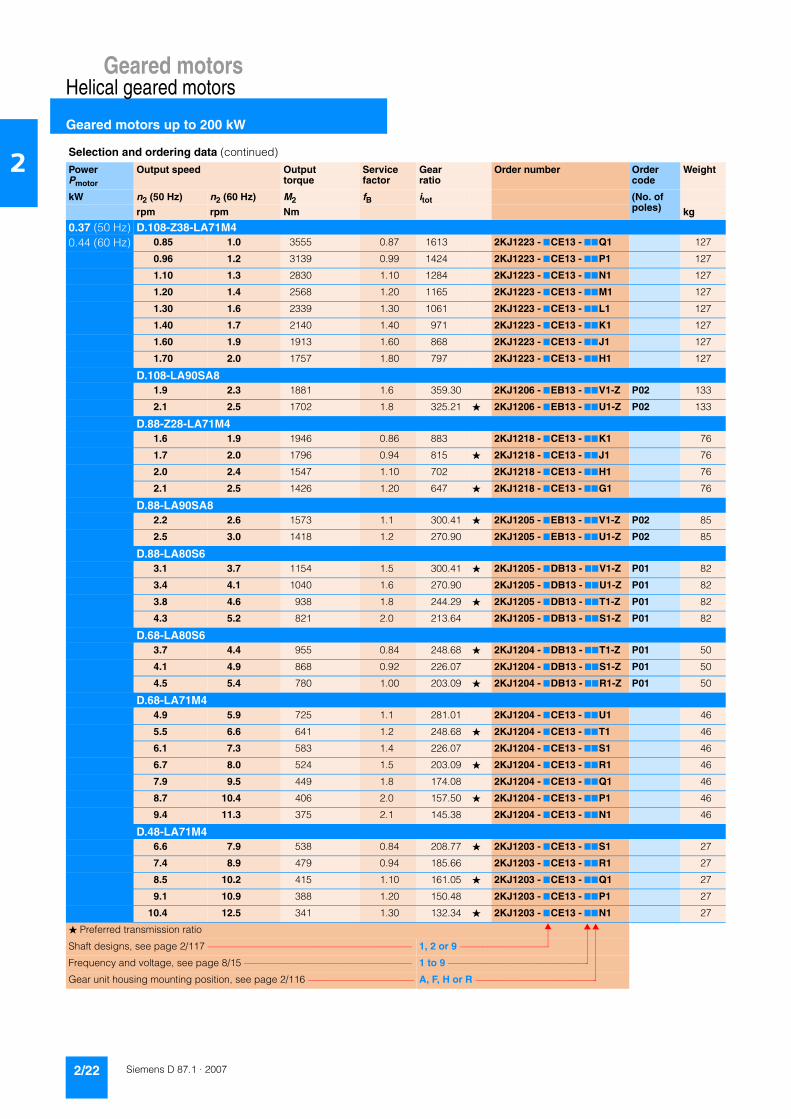
Geared motorsHelical geared motors
Geared motors up to 200 kW
2/22 Siemens D 87.1 · 2007
2
0.37 (50 Hz) D.108-Z38-LA71M40.44 (60 Hz) 0.85 1.0 3555 0.87 1613 2KJ1223 - 7CE13 - 77Q1 127
0.96 1.2 3139 0.99 1424 2KJ1223 - 7CE13 - 77P1 127
1.10 1.3 2830 1.10 1284 2KJ1223 - 7CE13 - 77N1 127
1.20 1.4 2568 1.20 1165 2KJ1223 - 7CE13 - 77M1 127
1.30 1.6 2339 1.30 1061 2KJ1223 - 7CE13 - 77L1 127
1.40 1.7 2140 1.40 971 2KJ1223 - 7CE13 - 77K1 127
1.60 1.9 1913 1.60 868 2KJ1223 - 7CE13 - 77J1 127
1.70 2.0 1757 1.80 797 2KJ1223 - 7CE13 - 77H1 127
D.108-LA90SA81.9 2.3 1881 1.6 359.30 2KJ1206 - 7EB13 - 77V1-Z P02 133
2.1 2.5 1702 1.8 325.21 � 2KJ1206 - 7EB13 - 77U1-Z P02 133
D.88-Z28-LA71M41.6 1.9 1946 0.86 883 2KJ1218 - 7CE13 - 77K1 76
1.7 2.0 1796 0.94 815 � 2KJ1218 - 7CE13 - 77J1 76
2.0 2.4 1547 1.10 702 2KJ1218 - 7CE13 - 77H1 76
2.1 2.5 1426 1.20 647 � 2KJ1218 - 7CE13 - 77G1 76
D.88-LA90SA82.2 2.6 1573 1.1 300.41 � 2KJ1205 - 7EB13 - 77V1-Z P02 85
2.5 3.0 1418 1.2 270.90 2KJ1205 - 7EB13 - 77U1-Z P02 85
D.88-LA80S63.1 3.7 1154 1.5 300.41 � 2KJ1205 - 7DB13 - 77V1-Z P01 82
3.4 4.1 1040 1.6 270.90 2KJ1205 - 7DB13 - 77U1-Z P01 82
3.8 4.6 938 1.8 244.29 � 2KJ1205 - 7DB13 - 77T1-Z P01 82
4.3 5.2 821 2.0 213.64 2KJ1205 - 7DB13 - 77S1-Z P01 82
D.68-LA80S63.7 4.4 955 0.84 248.68 � 2KJ1204 - 7DB13 - 77T1-Z P01 50
4.1 4.9 868 0.92 226.07 2KJ1204 - 7DB13 - 77S1-Z P01 50
4.5 5.4 780 1.00 203.09 � 2KJ1204 - 7DB13 - 77R1-Z P01 50
D.68-LA71M44.9 5.9 725 1.1 281.01 2KJ1204 - 7CE13 - 77U1 46
5.5 6.6 641 1.2 248.68 � 2KJ1204 - 7CE13 - 77T1 46
6.1 7.3 583 1.4 226.07 2KJ1204 - 7CE13 - 77S1 46
6.7 8.0 524 1.5 203.09 � 2KJ1204 - 7CE13 - 77R1 46
7.9 9.5 449 1.8 174.08 2KJ1204 - 7CE13 - 77Q1 46
8.7 10.4 406 2.0 157.50 � 2KJ1204 - 7CE13 - 77P1 46
9.4 11.3 375 2.1 145.38 2KJ1204 - 7CE13 - 77N1 46
D.48-LA71M46.6 7.9 538 0.84 208.77 � 2KJ1203 - 7CE13 - 77S1 27
7.4 8.9 479 0.94 185.66 2KJ1203 - 7CE13 - 77R1 27
8.5 10.2 415 1.10 161.05 � 2KJ1203 - 7CE13 - 77Q1 27
9.1 10.9 388 1.20 150.48 2KJ1203 - 7CE13 - 77P1 27
10.4 12.5 341 1.30 132.34 � 2KJ1203 - 7CE13 - 77N1 27
Selection and ordering data (continued)
PowerPmotor
Output speed Output torque
Service factor
Gear ratio
Order number Order code
Weight
kW n2 (50 Hz) n2 (60 Hz) M2 fB itot (No. of poles)rpm rpm Nm kg
� Preferred transmission ratio
Shaft designs, see page 2/117 –––––––––––––––––––––––––––––––––––––––––– 1, 2 or 9 –––––––––––––––––––
Frequency and voltage, see page 8/15 ––––––––––––––––––––––––––––––––––– 1 to 9 ––––––––––––––––––––––––––––––
Gear unit housing mounting position, see page 2/116 –––––––––––––––––––––– A, F, H or R ––––––––––––––––––––––––––

Geared motorsHelical geared motors
Geared motors up to 200 kW
2/23Siemens D 87.1 · 2007
2
0.37 (50 Hz) D.48-LA71M40.44 (60 Hz) 11.8 14.2 299 1.5 115.91 2KJ1203 - 7CE13 - 77M1 27
13.4 16.1 264 1.7 102.52 � 2KJ1203 - 7CE13 - 77L1 27
14.7 17.6 240 1.9 92.91 2KJ1203 - 7CE13 - 77K1 27
16.7 20.0 212 2.1 82.02 � 2KJ1203 - 7CE13 - 77J1 27
Z.48-LA71M427 32 132 2.2 51.28 2KJ1103 - 7CE13 - 77A2 27
D.38-LA71M413.2 15.8 268 0.82 103.89 2KJ1202 - 7CE13 - 77M1 18
15.0 18.0 236 0.93 91.34 � 2KJ1202 - 7CE13 - 77L1 18
16.6 19.9 213 1.00 82.52 2KJ1202 - 7CE13 - 77K1 18
19.1 23.0 185 1.20 71.91 � 2KJ1202 - 7CE13 - 77J1 18
21.0 25.0 167 1.30 64.58 2KJ1202 - 7CE13 - 77H1 18
24.0 29.0 150 1.50 58.30 � 2KJ1202 - 7CE13 - 77G1 18
26.0 31.0 136 1.60 52.86 2KJ1202 - 7CE13 - 77F1 18
28.0 34.0 124 1.80 48.10 � 2KJ1202 - 7CE13 - 77E1 18
Z.38-LA71M431 37 114 1.6 44.12 � 2KJ1102 - 7CE13 - 77A2 17
35 42 101 2.1 39.24 2KJ1102 - 7CE13 - 77X1 17
40 48 88 2.5 34.04 � 2KJ1102 - 7CE13 - 77W1 17
43 52 82 2.7 31.80 2KJ1102 - 7CE13 - 77V1 17
D.28-LA71M422 26 157 0.89 60.77 � 2KJ1201 - 7CE13 - 77C1 10
Z.28-LA71M427 32 132 1.1 51.35 2KJ1101 - 7CE13 - 77C2 10
32 38 112 1.3 43.30 � 2KJ1101 - 7CE13 - 77B2 10
36 43 99 1.4 38.45 2KJ1101 - 7CE13 - 77A2 10
41 49 87 1.6 33.71 � 2KJ1101 - 7CE13 - 77X1 10
45 54 78 1.8 30.16 2KJ1101 - 7CE13 - 77W1 10
51 61 69 2.0 26.77 � 2KJ1101 - 7CE13 - 77V1 10
58 70 60 2.3 23.46 2KJ1101 - 7CE13 - 77U1 10
66 79 53 2.6 20.63 � 2KJ1101 - 7CE13 - 77T1 10
74 89 48 2.9 18.63 2KJ1101 - 7CE13 - 77S1 10
84 101 42 3.3 16.24 � 2KJ1101 - 7CE13 - 77R1 10
Z.18-LA71M432 38 111 0.81 43.15 2KJ1100 - 7CE13 - 77U1 9
37 44 96 0.94 37.23 � 2KJ1100 - 7CE13 - 77T1 9
43 52 82 1.10 31.98 2KJ1100 - 7CE13 - 77S1 9
46 55 76 1.20 29.45 � 2KJ1100 - 7CE13 - 77R1 9
51 61 69 1.30 26.77 2KJ1100 - 7CE13 - 77Q1 9
58 70 61 1.50 23.69 � 2KJ1100 - 7CE13 - 77P1 9
69 83 51 1.80 19.85 2KJ1100 - 7CE13 - 77N1 9
81 97 44 2.10 16.92 � 2KJ1100 - 7CE13 - 77M1 9
95 114 37 2.40 14.38 � 2KJ1100 - 7CE13 - 77L1 9
110 132 32 2.80 12.50 2KJ1100 - 7CE13 - 77K1 9
Selection and ordering data (continued)
PowerPmotor
Output speed Output torque
Service factor
Gear ratio
Order number Order code
Weight
kW n2 (50 Hz) n2 (60 Hz) M2 fB itot (No. of poles)rpm rpm Nm kg
� Preferred transmission ratio
Shaft designs, see page 2/117 –––––––––––––––––––––––––––––––––––––––––– 1, 2 or 9 –––––––––––––––––––
Frequency and voltage, see page 8/15 ––––––––––––––––––––––––––––––––––– 1 to 9 ––––––––––––––––––––––––––––––
Gear unit housing mounting position, see page 2/116 –––––––––––––––––––––– A, F, H or R ––––––––––––––––––––––––––
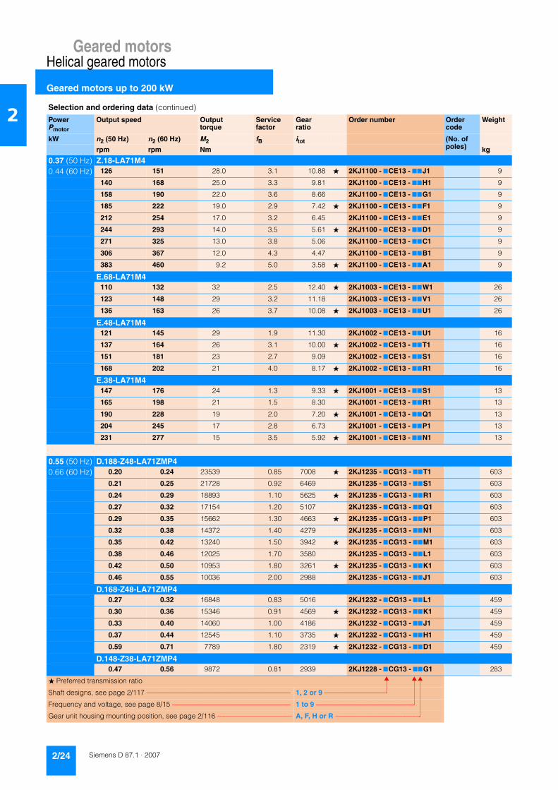
Geared motorsHelical geared motors
Geared motors up to 200 kW
2/24 Siemens D 87.1 · 2007
2
0.37 (50 Hz) Z.18-LA71M40.44 (60 Hz) 126 151 28.0 3.1 10.88 � 2KJ1100 - 7CE13 - 77J1 9
140 168 25.0 3.3 9.81 2KJ1100 - 7CE13 - 77H1 9
158 190 22.0 3.6 8.66 2KJ1100 - 7CE13 - 77G1 9
185 222 19.0 2.9 7.42 � 2KJ1100 - 7CE13 - 77F1 9
212 254 17.0 3.2 6.45 2KJ1100 - 7CE13 - 77E1 9
244 293 14.0 3.5 5.61 � 2KJ1100 - 7CE13 - 77D1 9
271 325 13.0 3.8 5.06 2KJ1100 - 7CE13 - 77C1 9
306 367 12.0 4.3 4.47 2KJ1100 - 7CE13 - 77B1 9
383 460 9.2 5.0 3.58 � 2KJ1100 - 7CE13 - 77A1 9
E.68-LA71M4110 132 32 2.5 12.40 � 2KJ1003 - 7CE13 - 77W1 26
123 148 29 3.2 11.18 2KJ1003 - 7CE13 - 77V1 26
136 163 26 3.7 10.08 � 2KJ1003 - 7CE13 - 77U1 26
E.48-LA71M4121 145 29 1.9 11.30 2KJ1002 - 7CE13 - 77U1 16
137 164 26 3.1 10.00 � 2KJ1002 - 7CE13 - 77T1 16
151 181 23 2.7 9.09 2KJ1002 - 7CE13 - 77S1 16
168 202 21 4.0 8.17 � 2KJ1002 - 7CE13 - 77R1 16
E.38-LA71M4147 176 24 1.3 9.33 � 2KJ1001 - 7CE13 - 77S1 13
165 198 21 1.5 8.30 2KJ1001 - 7CE13 - 77R1 13
190 228 19 2.0 7.20 � 2KJ1001 - 7CE13 - 77Q1 13
204 245 17 2.8 6.73 2KJ1001 - 7CE13 - 77P1 13
231 277 15 3.5 5.92 � 2KJ1001 - 7CE13 - 77N1 13
0.55 (50 Hz) D.188-Z48-LA71ZMP40.66 (60 Hz) 0.20 0.24 23539 0.85 7008 � 2KJ1235 - 7CG13 - 77T1 603
0.21 0.25 21728 0.92 6469 2KJ1235 - 7CG13 - 77S1 603
0.24 0.29 18893 1.10 5625 � 2KJ1235 - 7CG13 - 77R1 603
0.27 0.32 17154 1.20 5107 2KJ1235 - 7CG13 - 77Q1 603
0.29 0.35 15662 1.30 4663 � 2KJ1235 - 7CG13 - 77P1 603
0.32 0.38 14372 1.40 4279 2KJ1235 - 7CG13 - 77N1 603
0.35 0.42 13240 1.50 3942 � 2KJ1235 - 7CG13 - 77M1 603
0.38 0.46 12025 1.70 3580 2KJ1235 - 7CG13 - 77L1 603
0.42 0.50 10953 1.80 3261 � 2KJ1235 - 7CG13 - 77K1 603
0.46 0.55 10036 2.00 2988 2KJ1235 - 7CG13 - 77J1 603
D.168-Z48-LA71ZMP40.27 0.32 16848 0.83 5016 2KJ1232 - 7CG13 - 77L1 459
0.30 0.36 15346 0.91 4569 � 2KJ1232 - 7CG13 - 77K1 459
0.33 0.40 14060 1.00 4186 2KJ1232 - 7CG13 - 77J1 459
0.37 0.44 12545 1.10 3735 � 2KJ1232 - 7CG13 - 77H1 459
0.59 0.71 7789 1.80 2319 � 2KJ1232 - 7CG13 - 77D1 459
D.148-Z38-LA71ZMP40.47 0.56 9872 0.81 2939 2KJ1228 - 7CG13 - 77G1 283
Selection and ordering data (continued)
PowerPmotor
Output speed Output torque
Service factor
Gear ratio
Order number Order code
Weight
kW n2 (50 Hz) n2 (60 Hz) M2 fB itot (No. of poles)rpm rpm Nm kg
� Preferred transmission ratio
Shaft designs, see page 2/117 –––––––––––––––––––––––––––––––––––––––––– 1, 2 or 9 –––––––––––––––––––
Frequency and voltage, see page 8/15 ––––––––––––––––––––––––––––––––––– 1 to 9 ––––––––––––––––––––––––––––––
Gear unit housing mounting position, see page 2/116 –––––––––––––––––––––– A, F, H or R ––––––––––––––––––––––––––

Geared motorsHelical geared motors
Geared motors up to 200 kW
2/25Siemens D 87.1 · 2007
2
0.55 (50 Hz) D.148-Z38-LA71ZMP40.66 (60 Hz) 0.54 0.65 8491 0.94 2528 2KJ1228 - 7CG13 - 77F1 283
0.55 0.66 8468 0.94 2521 2KJ1228 - 7CG13 - 77E1 283
0.61 0.73 7571 1.10 2254 2KJ1228 - 7CG13 - 77D1 283
0.66 0.79 6953 1.20 2070 2KJ1228 - 7CG13 - 77C1 283
0.74 0.89 6264 1.30 1865 2KJ1228 - 7CG13 - 77B1 283
0.86 1.00 5388 1.50 1604 2KJ1228 - 7CG13 - 77A1 283
D.148-Z48-LA71ZMP40.84 1.0 5478 1.5 1631 2KJ1231 - 7CG13 - 77N1 292
0.92 1.1 5045 1.6 1502 2KJ1231 - 7CG13 - 77M1 292
1.00 1.2 4581 1.7 1364 2KJ1231 - 7CG13 - 77L1 292
1.10 1.3 4175 1.9 1243 2KJ1231 - 7CG13 - 77K1 292
D.128-Z38-LA71ZMP40.77 0.92 6039 0.84 1798 2KJ1225 - 7CG13 - 77D1 198
0.83 1.00 5545 0.92 1651 � 2KJ1225 - 7CG13 - 77C1 198
0.92 1.10 4998 1.00 1488 2KJ1225 - 7CG13 - 77B1 198
1.10 1.30 4299 1.20 1280 � 2KJ1225 - 7CG13 - 77A1 198
D.128-Z48-LA71ZMP41.1 1.3 4269 1.2 1271 2KJ1227 - 7CG13 - 77P1 208
1.2 1.4 3916 1.3 1166 2KJ1227 - 7CG13 - 77N1 208
1.3 1.6 3607 1.4 1074 2KJ1227 - 7CG13 - 77M1 208
1.4 1.7 3275 1.6 975 2KJ1227 - 7CG13 - 77L1 208
1.5 1.8 2986 1.7 889 2KJ1227 - 7CG13 - 77K1 208
1.7 2.0 2734 1.9 814 2KJ1227 - 7CG13 - 77J1 208
D.108-Z38-LA71ZMP41.3 1.6 3564 0.87 1061 2KJ1223 - 7CG13 - 77L1 127
1.4 1.7 3261 0.95 971 2KJ1223 - 7CG13 - 77K1 127
1.6 1.9 2915 1.10 868 2KJ1223 - 7CG13 - 77J1 127
1.7 2.0 2677 1.20 797 2KJ1223 - 7CG13 - 77H1 127
D.108-LA90LA81.9 2.3 2796 1.10 359.30 2KJ1206 - 7EE13 - 77V1-Z P02 136
2.1 2.5 2531 1.20 325.21 � 2KJ1206 - 7EE13 - 77U1-Z P02 136
2.4 2.9 2216 1.40 284.73 2KJ1206 - 7EE13 - 77T1-Z P02 136
D.108-LA80M62.5 3.0 2074 1.5 359.30 2KJ1206 - 7DC13 - 77V1-Z P01 130
2.8 3.4 1877 1.7 325.21 � 2KJ1206 - 7DC13 - 77U1-Z P01 130
3.2 3.8 1643 1.9 284.73 2KJ1206 - 7DC13 - 77T1-Z P01 130
D.88-LA90LA82.5 3.0 2108 0.8 270.90 2KJ1205 - 7EE13 - 77U1-Z P02 88
D.88-LA80M63.0 3.6 1734 0.97 300.41 � 2KJ1205 - 7DC13 - 77V1-Z P01 82
3.4 4.1 1564 1.10 270.90 2KJ1205 - 7DC13 - 77U1-Z P01 82
3.7 4.4 1410 1.20 244.29 � 2KJ1205 - 7DC13 - 77T1-Z P01 82
4.3 5.2 1233 1.40 213.64 2KJ1205 - 7DC13 - 77S1-Z P01 82
D.88-LA71ZMP44.6 5.5 1148 1.5 300.41 � 2KJ1205 - 7CG13 - 77V1-Z P01 78
Selection and ordering data (continued)
PowerPmotor
Output speed Output torque
Service factor
Gear ratio
Order number Order code
Weight
kW n2 (50 Hz) n2 (60 Hz) M2 fB itot (No. of poles)rpm rpm Nm kg
� Preferred transmission ratio
Shaft designs, see page 2/117 –––––––––––––––––––––––––––––––––––––––––– 1, 2 or 9 –––––––––––––––––––
Frequency and voltage, see page 8/15 ––––––––––––––––––––––––––––––––––– 1 to 9 ––––––––––––––––––––––––––––––
Gear unit housing mounting position, see page 2/116 –––––––––––––––––––––– A, F, H or R ––––––––––––––––––––––––––

Geared motorsHelical geared motors
Geared motors up to 200 kW
2/26 Siemens D 87.1 · 2007
2
0.55 (50 Hz) D.88-LA71ZMP40.66 (60 Hz) 5.1 6.1 1035 1.6 270.90 2KJ1205 - 7CG13 - 77U1-Z P01 78
5.6 6.7 933 1.8 244.29 � 2KJ1205 - 7CG13 - 77T1-Z P01 78
6.4 7.7 816 2.1 213.64 2KJ1205 - 7CG13 - 77S1-Z P01 78
D.68-LA71ZMP45.5 6.6 950 0.84 248.68 � 2KJ1204 - 7CG13 - 77T1 46
6.1 7.3 864 0.93 226.07 2KJ1204 - 7CG13 - 77S1 46
6.8 8.2 776 1.00 203.09 � 2KJ1204 - 7CG13 - 77R1 46
7.9 9.5 665 1.20 174.08 2KJ1204 - 7CG13 - 77Q1 46
8.7 10.4 602 1.30 157.50 � 2KJ1204 - 7CG13 - 77P1 46
9.5 11.4 555 1.40 145.38 2KJ1204 - 7CG13 - 77N1 46
10.9 13.1 483 1.70 126.41 � 2KJ1204 - 7CG13 - 77M1 46
12.0 14.4 438 1.80 114.78 2KJ1204 - 7CG13 - 77L1 46
13.1 15.7 400 2.00 104.80 � 2KJ1204 - 7CG13 - 77K1 46
14.3 17.2 367 2.20 96.16 2KJ1204 - 7CG13 - 77J1 46
D.48-LA71ZMP410.4 12.5 506 0.89 132.34 � 2KJ1203 - 7CG13 - 77N1 27
11.9 14.3 443 1.00 115.91 2KJ1203 - 7CG13 - 77M1 27
13.4 16.1 392 1.10 102.52 � 2KJ1203 - 7CG13 - 77L1 27
14.8 17.8 355 1.30 92.91 2KJ1203 - 7CG13 - 77K1 27
16.8 20.0 313 1.40 82.02 � 2KJ1203 - 7CG13 - 77J1 27
18.6 22.0 283 1.60 73.99 2KJ1203 - 7CG13 - 77H1 27
20.0 24.0 256 1.80 67.10 � 2KJ1203 - 7CG13 - 77G1 27
22.0 26.0 234 1.90 61.14 2KJ1203 - 7CG13 - 77F1 27
25.0 30.0 214 2.10 55.92 � 2KJ1203 - 7CG13 - 77E1 27
28.0 34.0 191 2.40 50.00 2KJ1203 - 7CG13 - 77D1 27
Z.48-LA71ZMP427 32 196 1.5 51.28 2KJ1103 - 7CG13 - 77A2 27
D.38-LA71ZMP419.1 23 275 0.80 71.91 � 2KJ1202 - 7CG13 - 77J1 18
21.0 25 247 0.89 64.58 2KJ1202 - 7CG13 - 77H1 18
24.0 29 223 0.99 58.30 � 2KJ1202 - 7CG13 - 77G1 18
26.0 31 202 1.10 52.86 2KJ1202 - 7CG13 - 77F1 18
Z.38-LA71ZMP431 37 169 1.10 44.12 � 2KJ1102 - 7CG13 - 77A2 17
35 42 150 1.40 39.24 2KJ1102 - 7CG13 - 77X1 17
40 48 130 1.70 34.04 � 2KJ1102 - 7CG13 - 77W1 17
43 52 121 1.80 31.80 2KJ1102 - 7CG13 - 77V1 17
49 59 107 2.10 27.97 � 2KJ1102 - 7CG13 - 77U1 17
56 67 94 2.40 24.50 2KJ1102 - 7CG13 - 77T1 17
64 77 83 2.70 21.67 � 2KJ1102 - 7CG13 - 77S1 17
70 84 75 2.90 19.64 2KJ1102 - 7CG13 - 77R1 17
Z.28-LA71ZMP432 38 165 0.85 43.30 � 2KJ1101 - 7CG13 - 77B2 10
36 43 147 0.95 38.45 2KJ1101 - 7CG13 - 77A2 10
Selection and ordering data (continued)
PowerPmotor
Output speed Output torque
Service factor
Gear ratio
Order number Order code
Weight
kW n2 (50 Hz) n2 (60 Hz) M2 fB itot (No. of poles)rpm rpm Nm kg
� Preferred transmission ratio
Shaft designs, see page 2/117 –––––––––––––––––––––––––––––––––––––––––– 1, 2 or 9 –––––––––––––––––––
Frequency and voltage, see page 8/15 ––––––––––––––––––––––––––––––––––– 1 to 9 ––––––––––––––––––––––––––––––
Gear unit housing mounting position, see page 2/116 –––––––––––––––––––––– A, F, H or R ––––––––––––––––––––––––––

Geared motorsHelical geared motors
Geared motors up to 200 kW
2/27Siemens D 87.1 · 2007
2
0.55 (50 Hz) Z.28-LA71ZMP40.66 (60 Hz) 41 49 129 1.1 33.71 � 2KJ1101 - 7CG13 - 77X1 10
46 55 115 1.2 30.16 2KJ1101 - 7CG13 - 77W1 10
51 61 102 1.4 26.77 � 2KJ1101 - 7CG13 - 77V1 10
59 71 90 1.6 23.46 2KJ1101 - 7CG13 - 77U1 10
67 80 79 1.8 20.63 � 2KJ1101 - 7CG13 - 77T1 10
74 89 71 2.0 18.63 2KJ1101 - 7CG13 - 77S1 10
85 102 62 2.3 16.24 � 2KJ1101 - 7CG13 - 77R1 10
94 113 56 2.5 14.58 2KJ1101 - 7CG13 - 77Q1 10
104 125 50 2.8 13.17 � 2KJ1101 - 7CG13 - 77P1 10
115 138 46 3.1 11.94 2KJ1101 - 7CG13 - 77N1 10
126 151 42 3.4 10.87 � 2KJ1101 - 7CG13 - 77M1 10
143 172 37 3.8 9.61 2KJ1101 - 7CG13 - 77L1 10
218 262 24 3.9 6.31 � 2KJ1101 - 7CG13 - 77G1 10
240 288 22 4.3 5.72 2KJ1101 - 7CG13 - 77F1 10
264 317 20 4.6 5.21 � 2KJ1101 - 7CG13 - 77E1 10
299 359 18 5.0 4.60 2KJ1101 - 7CG13 - 77D1 10
Z.18-LA71ZMP447 56 112 0.80 29.45 � 2KJ1100 - 7CG13 - 77R1 9
51 61 102 0.88 26.77 2KJ1100 - 7CG13 - 77Q1 9
58 70 90 0.99 23.69 � 2KJ1100 - 7CG13 - 77P1 9
69 83 76 1.20 19.85 2KJ1100 - 7CG13 - 77N1 9
81 97 65 1.40 16.92 � 2KJ1100 - 7CG13 - 77M1 9
96 115 55 1.60 14.38 � 2KJ1100 - 7CG13 - 77L1 9
110 132 48 1.90 12.50 2KJ1100 - 7CG13 - 77K1 9
126 151 42 2.10 10.88 � 2KJ1100 - 7CG13 - 77J1 9
140 168 38 2.20 9.81 2KJ1100 - 7CG13 - 77H1 9
159 191 33 2.40 8.66 2KJ1100 - 7CG13 - 77G1 9
185 222 28 1.90 7.42 � 2KJ1100 - 7CG13 - 77F1 9
213 256 25 2.20 6.45 2KJ1100 - 7CG13 - 77E1 9
245 294 21 2.40 5.61 � 2KJ1100 - 7CG13 - 77D1 9
272 326 19 2.50 5.06 2KJ1100 - 7CG13 - 77C1 9
308 370 17 2.90 4.47 2KJ1100 - 7CG13 - 77B1 9
384 461 14 3.40 3.58 � 2KJ1100 - 7CG13 - 77A1 9
E.68-LA71ZMP4111 133 47 1.7 12.40 � 2KJ1003 - 7CG13 - 77W1 26
123 148 43 2.2 11.18 2KJ1003 - 7CG13 - 77V1 26
136 163 38 2.5 10.08 � 2KJ1003 - 7CG13 - 77U1 26
E.48-LA71ZMP4122 146 43 1.3 11.30 2KJ1002 - 7CG13 - 77U1 16
138 166 38 2.1 10.00 � 2KJ1002 - 7CG13 - 77T1 16
151 181 35 1.8 9.09 2KJ1002 - 7CG13 - 77S1 16
168 202 31 2.7 8.17 � 2KJ1002 - 7CG13 - 77R1 16
196 235 27 3.6 7.00 2KJ1002 - 7CG13 - 77Q1 16
Selection and ordering data (continued)
PowerPmotor
Output speed Output torque
Service factor
Gear ratio
Order number Order code
Weight
kW n2 (50 Hz) n2 (60 Hz) M2 fB itot (No. of poles)rpm rpm Nm kg
� Preferred transmission ratio
Shaft designs, see page 2/117 –––––––––––––––––––––––––––––––––––––––––– 1, 2 or 9 –––––––––––––––––––
Frequency and voltage, see page 8/15 ––––––––––––––––––––––––––––––––––– 1 to 9 ––––––––––––––––––––––––––––––
Gear unit housing mounting position, see page 2/116 –––––––––––––––––––––– A, F, H or R ––––––––––––––––––––––––––

Geared motorsHelical geared motors
Geared motors up to 200 kW
2/28 Siemens D 87.1 · 2007
2
0.55 (50 Hz) E.38-LA71ZMP40.66 (60 Hz) 147 176 36 0.9 9.33 � 2KJ1001 - 7CG13 - 77S1 13
166 199 32 1.0 8.30 2KJ1001 - 7CG13 - 77R1 13
191 229 28 1.4 7.20 � 2KJ1001 - 7CG13 - 77Q1 13
204 245 26 1.9 6.73 2KJ1001 - 7CG13 - 77P1 13
232 278 23 2.3 5.92 � 2KJ1001 - 7CG13 - 77N1 13
265 318 20 3.5 5.18 2KJ1001 - 7CG13 - 77M1 13
300 360 18 4.5 4.58 � 2KJ1001 - 7CG13 - 77L1 13
331 397 16 3.9 4.15 2KJ1001 - 7CG13 - 77K1 13
375 450 14 5.0 3.67 � 2KJ1001 - 7CG13 - 77J1 13
415 498 13 5.1 3.31 2KJ1001 - 7CG13 - 77H1 13
0.75 (50 Hz) D.188-Z48-LA80M40.90 (60 Hz) 0.27 0.32 23410 0.85 5107 2KJ1235 - 7DC13 - 77Q1 607
0.30 0.36 21375 0.94 4663 � 2KJ1235 - 7DC13 - 77P1 607
0.33 0.40 19615 1.00 4279 2KJ1235 - 7DC13 - 77N1 607
0.35 0.42 18070 1.10 3942 � 2KJ1235 - 7DC13 - 77M1 607
0.39 0.47 16411 1.20 3580 2KJ1235 - 7DC13 - 77L1 607
0.43 0.52 14948 1.30 3261 � 2KJ1235 - 7DC13 - 77K1 607
0.47 0.56 13697 1.50 2988 2KJ1235 - 7DC13 - 77J1 607
0.52 0.62 12221 1.60 2666 � 2KJ1235 - 7DC13 - 77H1 607
0.59 0.71 10905 1.80 2379 2KJ1235 - 7DC13 - 77G1 607
0.37 0.44 17121 0.82 3735 � 2KJ1232 - 7DC13 - 77H1 463
D.168-Z48-LA80M40.42 0.50 15278 0.92 3333 2KJ1232 - 7DC13 - 77G1 463
0.49 0.59 12977 1.10 2831 2KJ1232 - 7DC13 - 77F1 463
0.59 0.71 10804 1.30 2357 � 2KJ1232 - 7DC13 - 77E1 463
0.60 0.72 10630 1.30 2319 � 2KJ1232 - 7DC13 - 77D1 463
0.67 0.80 9489 1.50 2070 2KJ1232 - 7DC13 - 77C1 463
0.79 0.95 8059 1.70 1758 2KJ1232 - 7DC13 - 77B1 463
D.148-Z48-LA80M40.85 1.0 7477 1.1 1631 2KJ1231 - 7DC13 - 77N1 296
0.93 1.1 6885 1.2 1502 2KJ1231 - 7DC13 - 77M1 296
1.00 1.2 6253 1.3 1364 2KJ1231 - 7DC13 - 77L1 296
1.10 1.3 5698 1.4 1243 2KJ1231 - 7DC13 - 77K1 296
1.20 1.4 5221 1.5 1139 2KJ1231 - 7DC13 - 77J1 296
1.40 1.7 4657 1.7 1016 2KJ1231 - 7DC13 - 77H1 296
1.50 1.8 4158 1.9 907 2KJ1231 - 7DC13 - 77G1 296
D.148-Z38-LA80M40.67 0.8 9489 0.84 2070 2KJ1228 - 7DC13 - 77C1 287
0.75 0.9 8549 0.94 1865 2KJ1228 - 7DC13 - 77B1 287
0.87 1.0 7353 1.10 1604 2KJ1228 - 7DC13 - 77A1 287
D.128-Z38-LA80M41.1 1.3 5868 0.87 1280 � 2KJ1225 - 7DC13 - 77A1 202
D.128-Z48-LA80M41.1 1.3 5826 0.88 1271 2KJ1227 - 7DC13 - 77P1 212
Selection and ordering data (continued)
PowerPmotor
Output speed Output torque
Service factor
Gear ratio
Order number Order code
Weight
kW n2 (50 Hz) n2 (60 Hz) M2 fB itot (No. of poles)rpm rpm Nm kg
� Preferred transmission ratio
Shaft designs, see page 2/117 –––––––––––––––––––––––––––––––––––––––––– 1, 2 or 9 –––––––––––––––––––
Frequency and voltage, see page 8/15 ––––––––––––––––––––––––––––––––––– 1 to 9 ––––––––––––––––––––––––––––––
Gear unit housing mounting position, see page 2/116 –––––––––––––––––––––– A, F, H or R ––––––––––––––––––––––––––
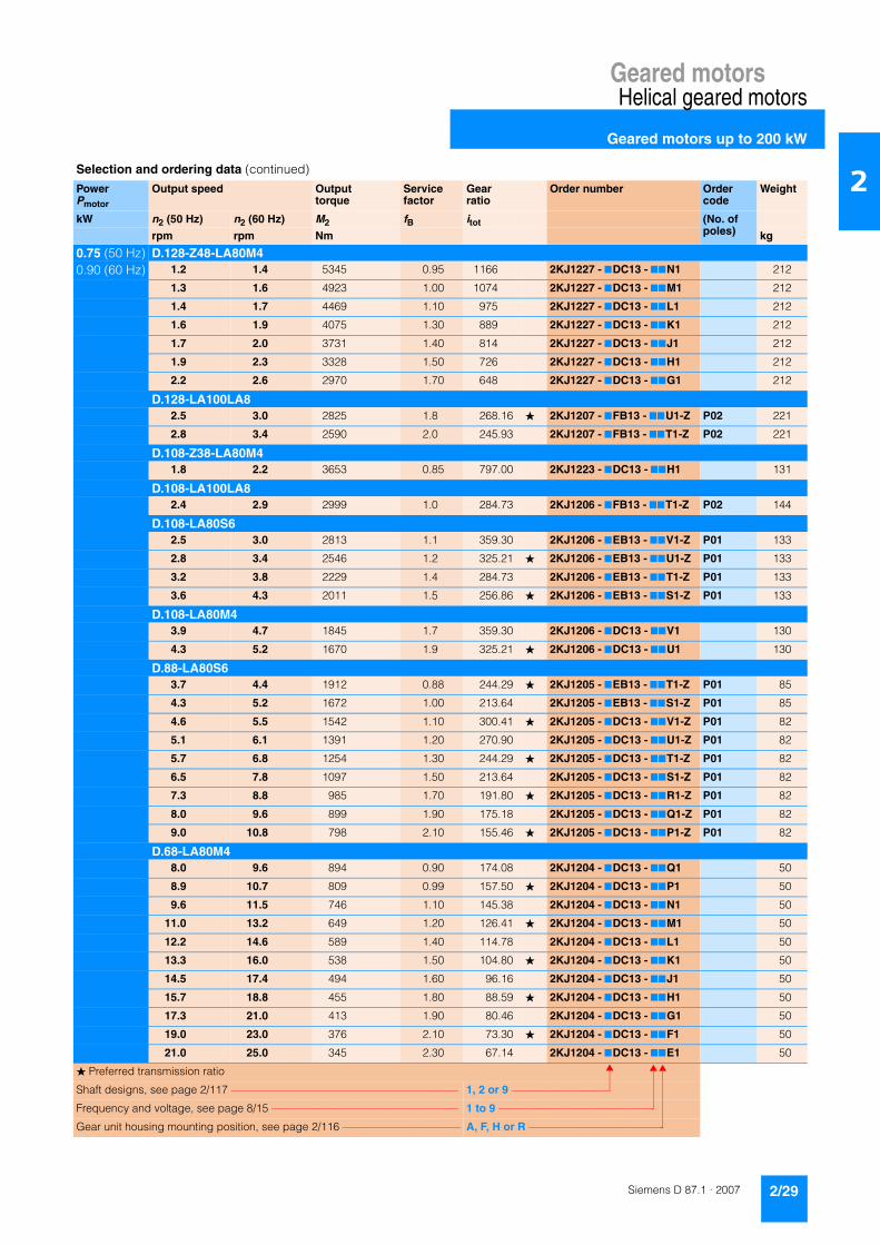
Geared motorsHelical geared motors
Geared motors up to 200 kW
2/29Siemens D 87.1 · 2007
2
0.75 (50 Hz) D.128-Z48-LA80M40.90 (60 Hz) 1.2 1.4 5345 0.95 1166 2KJ1227 - 7DC13 - 77N1 212
1.3 1.6 4923 1.00 1074 2KJ1227 - 7DC13 - 77M1 212
1.4 1.7 4469 1.10 975 2KJ1227 - 7DC13 - 77L1 212
1.6 1.9 4075 1.30 889 2KJ1227 - 7DC13 - 77K1 212
1.7 2.0 3731 1.40 814 2KJ1227 - 7DC13 - 77J1 212
1.9 2.3 3328 1.50 726 2KJ1227 - 7DC13 - 77H1 212
2.2 2.6 2970 1.70 648 2KJ1227 - 7DC13 - 77G1 212
D.128-LA100LA82.5 3.0 2825 1.8 268.16 � 2KJ1207 - 7FB13 - 77U1-Z P02 221
2.8 3.4 2590 2.0 245.93 2KJ1207 - 7FB13 - 77T1-Z P02 221
D.108-Z38-LA80M41.8 2.2 3653 0.85 797.00 2KJ1223 - 7DC13 - 77H1 131
D.108-LA100LA82.4 2.9 2999 1.0 284.73 2KJ1206 - 7FB13 - 77T1-Z P02 144
D.108-LA80S62.5 3.0 2813 1.1 359.30 2KJ1206 - 7EB13 - 77V1-Z P01 133
2.8 3.4 2546 1.2 325.21 � 2KJ1206 - 7EB13 - 77U1-Z P01 133
3.2 3.8 2229 1.4 284.73 2KJ1206 - 7EB13 - 77T1-Z P01 133
3.6 4.3 2011 1.5 256.86 � 2KJ1206 - 7EB13 - 77S1-Z P01 133
D.108-LA80M43.9 4.7 1845 1.7 359.30 2KJ1206 - 7DC13 - 77V1 130
4.3 5.2 1670 1.9 325.21 � 2KJ1206 - 7DC13 - 77U1 130
D.88-LA80S63.7 4.4 1912 0.88 244.29 � 2KJ1205 - 7EB13 - 77T1-Z P01 85
4.3 5.2 1672 1.00 213.64 2KJ1205 - 7EB13 - 77S1-Z P01 85
4.6 5.5 1542 1.10 300.41 � 2KJ1205 - 7DC13 - 77V1-Z P01 82
5.1 6.1 1391 1.20 270.90 2KJ1205 - 7DC13 - 77U1-Z P01 82
5.7 6.8 1254 1.30 244.29 � 2KJ1205 - 7DC13 - 77T1-Z P01 82
6.5 7.8 1097 1.50 213.64 2KJ1205 - 7DC13 - 77S1-Z P01 82
7.3 8.8 985 1.70 191.80 � 2KJ1205 - 7DC13 - 77R1-Z P01 82
8.0 9.6 899 1.90 175.18 2KJ1205 - 7DC13 - 77Q1-Z P01 82
9.0 10.8 798 2.10 155.46 � 2KJ1205 - 7DC13 - 77P1-Z P01 82
D.68-LA80M48.0 9.6 894 0.90 174.08 2KJ1204 - 7DC13 - 77Q1 50
8.9 10.7 809 0.99 157.50 � 2KJ1204 - 7DC13 - 77P1 50
9.6 11.5 746 1.10 145.38 2KJ1204 - 7DC13 - 77N1 50
11.0 13.2 649 1.20 126.41 � 2KJ1204 - 7DC13 - 77M1 50
12.2 14.6 589 1.40 114.78 2KJ1204 - 7DC13 - 77L1 50
13.3 16.0 538 1.50 104.80 � 2KJ1204 - 7DC13 - 77K1 50
14.5 17.4 494 1.60 96.16 2KJ1204 - 7DC13 - 77J1 50
15.7 18.8 455 1.80 88.59 � 2KJ1204 - 7DC13 - 77H1 50
17.3 21.0 413 1.90 80.46 2KJ1204 - 7DC13 - 77G1 50
19.0 23.0 376 2.10 73.30 � 2KJ1204 - 7DC13 - 77F1 50
21.0 25.0 345 2.30 67.14 2KJ1204 - 7DC13 - 77E1 50
Selection and ordering data (continued)
PowerPmotor
Output speed Output torque
Service factor
Gear ratio
Order number Order code
Weight
kW n2 (50 Hz) n2 (60 Hz) M2 fB itot (No. of poles)rpm rpm Nm kg
� Preferred transmission ratio
Shaft designs, see page 2/117 –––––––––––––––––––––––––––––––––––––––––– 1, 2 or 9 –––––––––––––––––––
Frequency and voltage, see page 8/15 ––––––––––––––––––––––––––––––––––– 1 to 9 ––––––––––––––––––––––––––––––
Gear unit housing mounting position, see page 2/116 –––––––––––––––––––––– A, F, H or R ––––––––––––––––––––––––––

Geared motorsHelical geared motors
Geared motors up to 200 kW
2/30 Siemens D 87.1 · 2007
2
0.75 (50 Hz) Z.68-LA80M40.90 (60 Hz) 29 35 247 2.2 48.09 � 2KJ1104 - 7DC13 - 77X1 48
D.48-LA80M413.6 16.3 526 0.85 102.52 � 2KJ1203 - 7DC13 - 77L1 31
15.0 18.0 477 0.94 92.91 2KJ1203 - 7DC13 - 77K1 31
17.0 20.0 421 1.10 82.02 � 2KJ1203 - 7DC13 - 77J1 31
18.9 23.0 380 1.20 73.99 2KJ1203 - 7DC13 - 77H1 31
21.0 25.0 345 1.30 67.10 � 2KJ1203 - 7DC13 - 77G1 31
23.0 28.0 314 1.40 61.14 2KJ1203 - 7DC13 - 77F1 31
25.0 30.0 287 1.60 55.92 � 2KJ1203 - 7DC13 - 77E1 31
28.0 34.0 257 1.80 50.00 2KJ1203 - 7DC13 - 77D1 31
Z.48-LA80M427 32 263 1.1 51.28 2KJ1103 - 7DC13 - 77A2 31
31 37 233 1.9 45.38 � 2KJ1103 - 7DC13 - 77X1 31
34 41 212 2.1 41.26 2KJ1103 - 7DC13 - 77W1 31
38 46 190 2.4 37.06 � 2KJ1103 - 7DC13 - 77V1 31
D.38-LA80M426 31 271 0.81 52.86 2KJ1202 - 7DC13 - 77F1 22
29 35 247 0.89 48.10 � 2KJ1202 - 7DC13 - 77E1 22
Z.38-LA80M432 38 227 0.8 44.12 � 2KJ1102 - 7DC13 - 77A2 21
36 43 201 1.0 39.24 2KJ1102 - 7DC13 - 77X1 21
41 49 175 1.3 34.04 � 2KJ1102 - 7DC13 - 77W1 21
44 53 163 1.3 31.80 2KJ1102 - 7DC13 - 77V1 21
50 60 144 1.5 27.97 � 2KJ1102 - 7DC13 - 77U1 21
57 68 126 1.7 24.50 2KJ1102 - 7DC13 - 77T1 21
64 77 111 2.0 21.67 � 2KJ1102 - 7DC13 - 77S1 21
71 85 101 2.2 19.64 2KJ1102 - 7DC13 - 77R1 21
80 96 89 2.5 17.33 � 2KJ1102 - 7DC13 - 77Q1 21
89 107 80 2.7 15.64 2KJ1102 - 7DC13 - 77P1 21
98 118 73 3.0 14.18 � 2KJ1102 - 7DC13 - 77N1 21
108 130 66 3.3 12.92 2KJ1102 - 7DC13 - 77M1 21
118 142 61 3.6 11.82 � 2KJ1102 - 7DC13 - 77L1 21
Z.28-LA71ZMD441 49 176 0.80 33.71 � 2KJ1101 - 7CH13 - 77X1 10
46 55 157 0.89 30.16 2KJ1101 - 7CH13 - 77W1 10
51 61 139 1.00 26.77 � 2KJ1101 - 7CH13 - 77V1 10
59 71 122 1.10 23.46 2KJ1101 - 7CH13 - 77U1 10
67 80 107 1.30 20.63 � 2KJ1101 - 7CH13 - 77T1 10
74 89 97 1.40 18.63 2KJ1101 - 7CH13 - 77S1 10
85 102 85 1.70 16.24 � 2KJ1101 - 7CH13 - 77R1 10
94 113 76 1.80 14.58 2KJ1101 - 7CH13 - 77Q1 10
104 125 69 2.00 13.17 � 2KJ1101 - 7CH13 - 77P1 10
115 138 62 2.30 11.94 2KJ1101 - 7CH13 - 77N1 10
126 151 57 2.50 10.87 � 2KJ1101 - 7CH13 - 77M1 10
Selection and ordering data (continued)
PowerPmotor
Output speed Output torque
Service factor
Gear ratio
Order number Order code
Weight
kW n2 (50 Hz) n2 (60 Hz) M2 fB itot (No. of poles)rpm rpm Nm kg
� Preferred transmission ratio
Shaft designs, see page 2/117 –––––––––––––––––––––––––––––––––––––––––– 1, 2 or 9 –––––––––––––––––––
Frequency and voltage, see page 8/15 ––––––––––––––––––––––––––––––––––– 1 to 9 ––––––––––––––––––––––––––––––
Gear unit housing mounting position, see page 2/116 –––––––––––––––––––––– A, F, H or R ––––––––––––––––––––––––––

Geared motorsHelical geared motors
Geared motors up to 200 kW
2/31Siemens D 87.1 · 2007
2
0.75 (50 Hz) Z.28-LA71ZMD40.90 (60 Hz) 143 172 50 2.8 9.61 2KJ1101 - 7CH13 - 77L1 10
155 186 46 3.0 8.87 � 2KJ1101 - 7CH13 - 77K1 10
180 216 40 3.4 7.64 2KJ1101 - 7CH13 - 77J1 10
198 238 36 3.7 6.94 � 2KJ1101 - 7CH13 - 77H1 10
218 262 33 2.9 6.31 � 2KJ1101 - 7CH13 - 77G1 10
240 288 30 3.1 5.72 2KJ1101 - 7CH13 - 77F1 10
264 317 27 3.4 5.21 � 2KJ1101 - 7CH13 - 77E1 10
299 359 24 3.7 4.60 2KJ1101 - 7CH13 - 77D1 10
324 389 22 4.1 4.25 � 2KJ1101 - 7CH13 - 77C1 10
376 451 19 4.2 3.66 2KJ1101 - 7CH13 - 77B1 10
413 496 17 4.4 3.33 � 2KJ1101 - 7CH13 - 77A1 10
Z.18-LA71ZMD469 83 103 0.87 19.85 2KJ1100 - 7CH13 - 77N1 9
81 97 88 1.00 16.92 � 2KJ1100 - 7CH13 - 77M1 9
96 115 75 1.20 14.38 � 2KJ1100 - 7CH13 - 77L1 9
110 132 65 1.40 12.50 2KJ1100 - 7CH13 - 77K1 9
126 151 57 1.50 10.88 � 2KJ1100 - 7CH13 - 77J1 9
140 168 51 1.60 9.81 2KJ1100 - 7CH13 - 77H1 9
159 191 45 1.80 8.66 2KJ1100 - 7CH13 - 77G1 9
185 222 39 1.40 7.42 � 2KJ1100 - 7CH13 - 77F1 9
213 256 34 1.60 6.45 2KJ1100 - 7CH13 - 77E1 9
245 294 29 1.70 5.61 � 2KJ1100 - 7CH13 - 77D1 9
272 326 26 1.90 5.06 2KJ1100 - 7CH13 - 77C1 9
308 370 23 2.10 4.47 2KJ1100 - 7CH13 - 77B1 9
384 461 19 2.50 3.58 � 2KJ1100 - 7CH13 - 77A1 9
E.68-LA80M4112 134 64 1.3 12.40 � 2KJ1003 - 7DC13 - 77W1 30
125 150 57 1.6 11.18 2KJ1003 - 7DC13 - 77V1 30
138 166 52 1.8 10.08 � 2KJ1003 - 7DC13 - 77U1 30
158 190 45 3.3 8.82 2KJ1003 - 7DC13 - 77T1 30
176 211 41 4.2 7.92 � 2KJ1003 - 7DC13 - 77S1 30
193 232 37 4.0 7.23 2KJ1003 - 7DC13 - 77R1 30
E.48-LA80M4123 148 58 0.95 11.30 2KJ1002 - 7DC13 - 77U1 20
140 168 51 1.60 10.00 � 2KJ1002 - 7DC13 - 77T1 20
153 184 47 1.40 9.09 2KJ1002 - 7DC13 - 77S1 20
171 205 42 2.00 8.17 � 2KJ1002 - 7DC13 - 77R1 20
199 239 36 2.70 7.00 2KJ1002 - 7DC13 - 77Q1 20
220 264 32 3.50 6.33 � 2KJ1002 - 7DC13 - 77P1 20
238 286 30 4.00 5.85 2KJ1002 - 7DC13 - 77N1 20
275 330 26 4.60 5.08 � 2KJ1002 - 7DC13 - 77M1 20
E.38-LA80M4194 233 37 1.0 7.20 � 2KJ1001 - 7DC13 - 77Q1 17
207 248 35 1.4 6.73 2KJ1001 - 7DC13 - 77P1 17
236 283 30 1.7 5.92 � 2KJ1001 - 7DC13 - 77N1 17
Selection and ordering data (continued)
PowerPmotor
Output speed Output torque
Service factor
Gear ratio
Order number Order code
Weight
kW n2 (50 Hz) n2 (60 Hz) M2 fB itot (No. of poles)rpm rpm Nm kg
� Preferred transmission ratio
Shaft designs, see page 2/117 –––––––––––––––––––––––––––––––––––––––––– 1, 2 or 9 –––––––––––––––––––
Frequency and voltage, see page 8/15 ––––––––––––––––––––––––––––––––––– 1 to 9 ––––––––––––––––––––––––––––––
Gear unit housing mounting position, see page 2/116 –––––––––––––––––––––– A, F, H or R ––––––––––––––––––––––––––

Geared motorsHelical geared motors
Geared motors up to 200 kW
2/32 Siemens D 87.1 · 2007
2
0.75 (50 Hz) E.38-LA80M40.90 (60 Hz) 269 323 27 2.6 5.18 2KJ1001 - 7DC13 - 77M1 17
305 366 24 3.3 4.58 � 2KJ1001 - 7DC13 - 77L1 17
336 403 21 2.9 4.15 2KJ1001 - 7DC13 - 77K1 17
380 456 19 3.7 3.67 � 2KJ1001 - 7DC13 - 77J1 17
421 505 17 3.8 3.31 2KJ1001 - 7DC13 - 77H1 17
465 558 15 5.2 3.00 � 2KJ1001 - 7DC13 - 77G1 17
511 613 14 5.7 2.73 2KJ1001 - 7DC13 - 77F1 17
558 670 13 5.7 2.50 � 2KJ1001 - 7DC13 - 77E1 17
1.1 (50 Hz) D.188-Z48-LA90S41.3 (60 Hz) 0.40 0.48 24043 0.83 3580 2KJ1235 - 7EL13 - 77L1 610
0.43 0.52 21901 0.91 3261 � 2KJ1235 - 7EL13 - 77K1 610
0.47 0.56 20068 1.00 2988 2KJ1235 - 7EL13 - 77J1 610
0.53 0.64 17905 1.10 2666 � 2KJ1235 - 7EL13 - 77H1 610
0.59 0.71 15977 1.30 2379 2KJ1235 - 7EL13 - 77G1 610
0.70 0.84 13573 1.50 2021 2KJ1235 - 7EL13 - 77F1 610
0.84 1.00 11296 1.80 1682 � 2KJ1235 - 7EL13 - 77E1 610
0.85 1.00 11115 1.80 1655 � 2KJ1235 - 7EL13 - 77D1 610
0.96 1.20 9920 2.00 1477 2KJ1235 - 7EL13 - 77C1 610
D.168-Z48-LA90S40.60 0.72 15830 0.88 2357 � 2KJ1232 - 7EL13 - 77E1 466
0.61 0.73 15575 0.90 2319 � 2KJ1232 - 7EL13 - 77D1 466
0.68 0.82 13902 1.00 2070 2KJ1232 - 7EL13 - 77C1 466
0.81 0.97 11807 1.20 1758 2KJ1232 - 7EL13 - 77B1 466
0.97 1.20 9826 1.40 1463 � 2KJ1232 - 7EL13 - 77A1 466
D.168-Z68-LA90S40.97 1.2 9812 1.4 1461 2KJ1233 - 7EL13 - 77J1 483
1.20 1.4 8234 1.7 1226 2KJ1233 - 7EL13 - 77H1 483
1.40 1.7 7025 2.0 1046 2KJ1233 - 7EL13 - 77G1 483
D.148-Z48-LA90S41.0 1.2 9161 0.87 1364 2KJ1231 - 7EL13 - 77L1 299
1.1 1.3 8348 0.96 1243 2KJ1231 - 7EL13 - 77K1 299
1.2 1.4 7650 1.00 1139 2KJ1231 - 7EL13 - 77J1 299
1.4 1.7 6824 1.20 1016 2KJ1231 - 7EL13 - 77H1 299
1.6 1.9 6091 1.30 907 2KJ1231 - 7EL13 - 77G1 299
1.8 2.2 5171 1.50 770 2KJ1231 - 7EL13 - 77F1 299
D.148-LA100L82.0 2.4 5192 1.5 336.11 2KJ1208 - 7FL13 - 77W1-Z P02 311
2.3 2.8 4655 1.7 301.34 � 2KJ1208 - 7FL13 - 77V1-Z P02 311
2.5 3.0 4267 1.9 276.23 2KJ1208 - 7FL13 - 77U1-Z P02 311
2.7 3.2 3935 2.0 254.70 � 2KJ1208 - 7FL13 - 77T1-Z P02 311
D.128-Z48-LA90S41.6 1.9 5971 0.85 889 2KJ1227 - 7EL13 - 77K1 215
1.7 2.0 5467 0.93 814 2KJ1227 - 7EL13 - 77J1 215
1.9 2.3 4876 1.00 726 2KJ1227 - 7EL13 - 77H1 215
Selection and ordering data (continued)
PowerPmotor
Output speed Output torque
Service factor
Gear ratio
Order number Order code
Weight
kW n2 (50 Hz) n2 (60 Hz) M2 fB itot (No. of poles)rpm rpm Nm kg
� Preferred transmission ratio
Shaft designs, see page 2/117 –––––––––––––––––––––––––––––––––––––––––– 1, 2 or 9 –––––––––––––––––––
Frequency and voltage, see page 8/15 ––––––––––––––––––––––––––––––––––– 1 to 9 ––––––––––––––––––––––––––––––
Gear unit housing mounting position, see page 2/116 –––––––––––––––––––––– A, F, H or R ––––––––––––––––––––––––––

Geared motorsHelical geared motors
Geared motors up to 200 kW
2/33Siemens D 87.1 · 2007
2
1.1 (50 Hz) D.128-Z48-LA90S41.3 (60 Hz) 2.2 2.6 4352 1.2 648.00 2KJ1227 - 7EL13 - 77G1 215
D.128-LA100L82.5 3.0 4143 1.2 268.16 � 2KJ1207 - 7FL13 - 77U1-Z P02 221
2.8 3.4 3799 1.3 245.93 2KJ1207 - 7FL13 - 77T1-Z P02 221
3.1 3.7 3394 1.5 219.72 � 2KJ1207 - 7FL13 - 77S1-Z P02 221
D.128-LA90L63.4 4.1 3079 1.7 268.16 � 2KJ1207 - 7EP13 - 77U1-Z P01 213
3.7 4.4 2823 1.8 245.93 2KJ1207 - 7EP13 - 77T1-Z P01 213
4.2 5.0 2523 2.0 219.72 � 2KJ1207 - 7EP13 - 77S1-Z P01 213
D.108-LA90L62.8 3.4 3734 0.83 325.21 � 2KJ1206 - 7EP13 - 77U1-Z P01 136
3.2 3.8 3269 0.95 284.73 2KJ1206 - 7EP13 - 77T1-Z P01 136
3.6 4.3 2949 1.10 256.86 � 2KJ1206 - 7EP13 - 77S1-Z P01 136
D.108-LA90S43.9 4.7 2667 1.2 359.30 2KJ1206 - 7EL13 - 77V1 133
4.4 5.3 2414 1.3 325.21 � 2KJ1206 - 7EL13 - 77U1 133
5.0 6.0 2114 1.5 284.73 2KJ1206 - 7EL13 - 77T1 133
5.5 6.6 1907 1.6 256.86 � 2KJ1206 - 7EL13 - 77S1 133
6.0 7.2 1746 1.8 235.19 2KJ1206 - 7EL13 - 77R1 133
6.8 8.2 1553 2.0 209.21 � 2KJ1206 - 7EL13 - 77Q1 133
D.88-LA90S45.2 6.2 2011 0.84 270.90 2KJ1205 - 7EL13 - 77U1 85
5.8 7.0 1814 0.93 244.29 � 2KJ1205 - 7EL13 - 77T1 85
6.6 7.9 1586 1.10 213.64 2KJ1205 - 7EL13 - 77S1 85
7.4 8.9 1424 1.20 191.80 � 2KJ1205 - 7EL13 - 77R1 85
8.1 9.7 1301 1.30 175.18 2KJ1205 - 7EL13 - 77Q1 85
9.1 10.9 1154 1.50 155.46 � 2KJ1205 - 7EL13 - 77P1 85
9.9 11.9 1065 1.60 143.50 2KJ1205 - 7EL13 - 77N1 85
10.9 13.1 964 1.70 129.79 � 2KJ1205 - 7EL13 - 77M1 85
11.8 14.2 887 1.90 119.52 2KJ1205 - 7EL13 - 77L1 85
12.8 15.4 821 2.00 110.54 � 2KJ1205 - 7EL13 - 77K1 85
13.8 16.6 762 2.20 102.61 2KJ1205 - 7EL13 - 77J1 85
D.68-LA90S411.2 13.4 938 0.85 126.41 � 2KJ1204 - 7EL13 - 77M1 53
12.3 14.8 852 0.94 114.78 2KJ1204 - 7EL13 - 77L1 53
13.5 16.2 778 1.00 104.80 � 2KJ1204 - 7EL13 - 77K1 53
14.7 17.6 714 1.10 96.16 2KJ1204 - 7EL13 - 77J1 53
16.0 19.2 658 1.20 88.59 � 2KJ1204 - 7EL13 - 77H1 53
17.6 21.0 597 1.30 80.46 2KJ1204 - 7EL13 - 77G1 53
19.3 23.0 544 1.50 73.30 � 2KJ1204 - 7EL13 - 77F1 53
21.0 25.0 498 1.60 67.14 2KJ1204 - 7EL13 - 77E1 53
24.0 29.0 445 1.80 59.91 � 2KJ1204 - 7EL13 - 77D1 53
26.0 31.0 397 2.00 53.47 2KJ1204 - 7EL13 - 77C1 53
Selection and ordering data (continued)
PowerPmotor
Output speed Output torque
Service factor
Gear ratio
Order number Order code
Weight
kW n2 (50 Hz) n2 (60 Hz) M2 fB itot (No. of poles)rpm rpm Nm kg
� Preferred transmission ratio
Shaft designs, see page 2/117 –––––––––––––––––––––––––––––––––––––––––– 1, 2 or 9 –––––––––––––––––––
Frequency and voltage, see page 8/15 ––––––––––––––––––––––––––––––––––– 1 to 9 ––––––––––––––––––––––––––––––
Gear unit housing mounting position, see page 2/116 –––––––––––––––––––––– A, F, H or R ––––––––––––––––––––––––––

Geared motorsHelical geared motors
Geared motors up to 200 kW
2/34 Siemens D 87.1 · 2007
2
1.1 (50 Hz) Z.68-LA90S41.3 (60 Hz) 29 35 357 1.5 48.09 � 2KJ1104 - 7EL13 - 77X1 51
34 41 312 2.6 42.06 2KJ1104 - 7EL13 - 77W1 51
D.48-LA90S419.1 23 549 0.82 73.99 2KJ1203 - 7EL13 - 77H1 34
21.0 25 498 0.90 67.10 � 2KJ1203 - 7EL13 - 77G1 34
23.0 28 454 0.99 61.14 2KJ1203 - 7EL13 - 77F1 34
25.0 30 415 1.10 55.92 � 2KJ1203 - 7EL13 - 77E1 34
28.0 34 371 1.20 50.00 2KJ1203 - 7EL13 - 77D1 34
Z.48-LA90S431 37 337 1.3 45.38 � 2KJ1103 - 7EL13 - 77X1 34
34 41 306 1.5 41.26 2KJ1103 - 7EL13 - 77W1 34
38 46 275 1.6 37.06 � 2KJ1103 - 7EL13 - 77V1 34
44 53 236 1.9 31.77 2KJ1103 - 7EL13 - 77U1 34
49 59 213 2.1 28.74 � 2KJ1103 - 7EL13 - 77T1 34
53 64 197 2.3 26.53 2KJ1103 - 7EL13 - 77S1 34
61 73 171 2.6 23.07 � 2KJ1103 - 7EL13 - 77R1 34
68 82 156 2.9 20.95 2KJ1103 - 7EL13 - 77Q1 34
74 89 142 3.2 19.13 � 2KJ1103 - 7EL13 - 77P1 34
Z.38-LA90S442 50 253 0.87 34.04 � 2KJ1102 - 7EL13 - 77W1 24
44 53 236 0.93 31.80 2KJ1102 - 7EL13 - 77V1 24
51 61 208 1.10 27.97 � 2KJ1102 - 7EL13 - 77U1 24
58 70 182 1.20 24.50 2KJ1102 - 7EL13 - 77T1 24
65 78 161 1.40 21.67 � 2KJ1102 - 7EL13 - 77S1 24
72 86 146 1.50 19.64 2KJ1102 - 7EL13 - 77R1 24
82 98 129 1.70 17.33 � 2KJ1102 - 7EL13 - 77Q1 24
90 108 116 1.90 15.64 2KJ1102 - 7EL13 - 77P1 24
100 120 105 2.10 14.18 � 2KJ1102 - 7EL13 - 77N1 24
110 132 96 2.30 12.92 2KJ1102 - 7EL13 - 77M1 24
120 144 88 2.50 11.82 � 2KJ1102 - 7EL13 - 77L1 24
134 161 78 2.70 10.57 2KJ1102 - 7EL13 - 77K1 24
146 175 72 2.80 9.70 � 2KJ1102 - 7EL13 - 77J1 24
162 194 65 3.00 8.75 2KJ1102 - 7EL13 - 77H1 24
188 226 56 3.40 7.52 � 2KJ1102 - 7EL13 - 77G1 24
189 227 56 3.30 7.50 � 2KJ1102 - 7EL13 - 77F1 24
211 253 50 3.60 6.71 2KJ1102 - 7EL13 - 77D1 24
230 276 46 3.70 6.16 � 2KJ1102 - 7EL13 - 77C1 24
255 306 41 4.00 5.55 2KJ1102 - 7EL13 - 77B1 24
297 356 35 4.50 4.77 � 2KJ1102 - 7EL13 - 77A1 24
Z.28-LA90S460 72 174 0.80 23.46 2KJ1101 - 7EL13 - 77U1 17
69 83 153 0.91 20.63 � 2KJ1101 - 7EL13 - 77T1 17
76 91 138 1.00 18.63 2KJ1101 - 7EL13 - 77S1 17
87 104 121 1.20 16.24 � 2KJ1101 - 7EL13 - 77R1 17
Selection and ordering data (continued)
PowerPmotor
Output speed Output torque
Service factor
Gear ratio
Order number Order code
Weight
kW n2 (50 Hz) n2 (60 Hz) M2 fB itot (No. of poles)rpm rpm Nm kg
� Preferred transmission ratio
Shaft designs, see page 2/117 –––––––––––––––––––––––––––––––––––––––––– 1, 2 or 9 –––––––––––––––––––
Frequency and voltage, see page 8/15 ––––––––––––––––––––––––––––––––––– 1 to 9 ––––––––––––––––––––––––––––––
Gear unit housing mounting position, see page 2/116 –––––––––––––––––––––– A, F, H or R ––––––––––––––––––––––––––

Geared motorsHelical geared motors
Geared motors up to 200 kW
2/35Siemens D 87.1 · 2007
2
1.1 (50 Hz) Z.28-LA90S41.3 (60 Hz) 97 116 108 1.3 14.58 2KJ1101 - 7EL13 - 77Q1 17
107 128 98 1.4 13.17 � 2KJ1101 - 7EL13 - 77P1 17
119 143 89 1.6 11.94 2KJ1101 - 7EL13 - 77N1 17
130 156 81 1.7 10.87 � 2KJ1101 - 7EL13 - 77M1 17
147 176 71 2.0 9.61 2KJ1101 - 7EL13 - 77L1 17
160 192 66 2.1 8.87 � 2KJ1101 - 7EL13 - 77K1 17
185 222 57 2.4 7.64 2KJ1101 - 7EL13 - 77J1 17
204 245 52 2.6 6.94 � 2KJ1101 - 7EL13 - 77H1 17
224 269 47 2.0 6.31 � 2KJ1101 - 7EL13 - 77G1 17
247 296 42 2.2 5.72 2KJ1101 - 7EL13 - 77F1 17
272 326 39 2.4 5.21 � 2KJ1101 - 7EL13 - 77E1 17
308 370 34 2.6 4.60 2KJ1101 - 7EL13 - 77D1 17
333 400 32 2.9 4.25 � 2KJ1101 - 7EL13 - 77C1 17
387 464 27 2.9 3.66 2KJ1101 - 7EL13 - 77B1 17
425 510 25 3.1 3.33 � 2KJ1101 - 7EL13 - 77A1 17
E.88-LA90S4137 164 77 3.0 10.33 � 2KJ1004 - 7EL13 - 77S1 50
150 180 70 3.0 9.46 2KJ1004 - 7EL13 - 77R1 50
168 202 62 3.9 8.42 � 2KJ1004 - 7EL13 - 77Q1 50
184 221 57 4.3 7.69 2KJ1004 - 7EL13 - 77P1 50
E.68-LA90S4114 137 92 0.88 12.40 � 2KJ1003 - 7EL13 - 77W1 33
127 152 83 1.10 11.18 2KJ1003 - 7EL13 - 77V1 33
140 168 75 1.30 10.08 � 2KJ1003 - 7EL13 - 77U1 33
160 192 66 2.30 8.82 2KJ1003 - 7EL13 - 77T1 33
179 215 59 2.90 7.92 � 2KJ1003 - 7EL13 - 77S1 33
196 235 54 2.80 7.23 2KJ1003 - 7EL13 - 77R1 33
220 264 48 3.60 6.42 � 2KJ1003 - 7EL13 - 77P1 33
239 287 44 4.30 5.92 2KJ1003 - 7EL13 - 77N1 33
E.48-LA90S4142 170 74 1.10 10.00 � 2KJ1002 - 7EL13 - 77T1 23
156 187 68 0.95 9.09 2KJ1002 - 7EL13 - 77S1 23
173 208 61 1.40 8.17 � 2KJ1002 - 7EL13 - 77R1 23
202 242 52 1.90 7.00 2KJ1002 - 7EL13 - 77Q1 23
224 269 47 2.40 6.33 � 2KJ1002 - 7EL13 - 77P1 23
242 290 43 2.80 5.85 2KJ1002 - 7EL13 - 77N1 23
279 335 38 3.20 5.08 � 2KJ1002 - 7EL13 - 77M1 23
306 367 34 3.80 4.62 2KJ1002 - 7EL13 - 77L1 23
336 403 31 4.80 4.21 � 2KJ1002 - 7EL13 - 77K1 23
397 476 26 5.30 3.56 � 2KJ1002 - 7EL13 - 77H1 23
E.38-LA90S4210 252 50 0.96 6.73 2KJ1001 - 7EL13 - 77P1 20
239 287 44 1.20 5.92 � 2KJ1001 - 7EL13 - 77N1 20
273 328 38 1.80 5.18 2KJ1001 - 7EL13 - 77M1 20
309 371 34 2.30 4.58 � 2KJ1001 - 7EL13 - 77L1 20
Selection and ordering data (continued)
PowerPmotor
Output speed Output torque
Service factor
Gear ratio
Order number Order code
Weight
kW n2 (50 Hz) n2 (60 Hz) M2 fB itot (No. of poles)rpm rpm Nm kg
� Preferred transmission ratio
Shaft designs, see page 2/117 –––––––––––––––––––––––––––––––––––––––––– 1, 2 or 9 –––––––––––––––––––
Frequency and voltage, see page 8/15 ––––––––––––––––––––––––––––––––––– 1 to 9 ––––––––––––––––––––––––––––––
Gear unit housing mounting position, see page 2/116 –––––––––––––––––––––– A, F, H or R ––––––––––––––––––––––––––

Geared motorsHelical geared motors
Geared motors up to 200 kW
2/36 Siemens D 87.1 · 2007
2
1.1 (50 Hz) E.38-LA90S41.3 (60 Hz) 341 409 31 2.0 4.15 2KJ1001 - 7EL13 - 77K1 20
386 463 27 2.6 3.67 � 2KJ1001 - 7EL13 - 77L1 20
427 512 25 2.6 3.31 2KJ1001 - 7EL13 - 77H1 20
472 566 22 3.6 3.00 � 2KJ1001 - 7EL13 - 77G1 20
518 622 20 3.9 2.73 2KJ1001 - 7EL13 - 77F1 20
566 679 19 3.9 2.50 � 2KJ1001 - 7EL13 - 77E1 20
632 758 17 4.3 2.24 2KJ1001 - 7EL13 - 77D1 20
690 828 15 5.3 2.05 � 2KJ1001 - 7EL13 - 77C1 20
765 918 14 6.0 1.85 2KJ1001 - 7EL13 - 77B1 20
890 1068 12 6.1 1.59 � 2KJ1001 - 7EL13 - 77A1 20
1.5 (50 Hz) D.188-Z48-LA90L41.8 (60 Hz) 0.53 0.64 24512 0.82 2666 � 2KJ1235 - 7EP13 - 77H1 613
0.60 0.72 21873 0.91 2379 2KJ1235 - 7EP13 - 77G1 613
0.70 0.84 18582 1.10 2021 2KJ1235 - 7EP13 - 77F1 613
0.84 1.00 15465 1.30 1682 � 2KJ1235 - 7EP13 - 77E1 613
0.86 1.00 15216 1.30 1655 � 2KJ1235 - 7EP13 - 77D1 613
0.96 1.20 13580 1.50 1477 2KJ1235 - 7EP13 - 77C1 613
1.10 1.30 11539 1.70 1255 2KJ1235 - 7EP13 - 77B1 613
D.188-Z68-LA90L41.1 1.3 11502 1.7 1251 2KJ1237 - 7EP13 - 77J1 630
D.168-Z48-LA90L40.81 0.97 16163 0.87 1758 2KJ1232 - 7EP13 - 77B1 469
0.97 1.20 13451 1.00 1463 � 2KJ1232 - 7EP13 - 77A1 469
D.168-Z68-LA90L40.97 1.2 13433 1.0 1461 2KJ1233 - 7EP13 - 77J1 486
1.20 1.4 11272 1.2 1226 2KJ1233 - 7EP13 - 77H1 486
1.40 1.7 9617 1.5 1046 2KJ1233 - 7EP13 - 77G1 486
D.148-Z48-LA90L41.4 1.7 9341 0.86 1016 2KJ1231 - 7EP13 - 77H1 302
1.6 1.9 8339 0.96 907 2KJ1231 - 7EP13 - 77G1 302
1.8 2.2 7080 1.10 770 2KJ1231 - 7EP13 - 77F1 302
D.148-LA112M82.1 2.5 6829 1.2 336.11 2KJ1208 - 7GG13 - 77W1-Z P02 318
2.3 2.8 6123 1.3 301.34 � 2KJ1208 - 7GG13 - 77V1-Z P02 318
2.6 3.1 5613 1.4 276.23 2KJ1208 - 7GG13 - 77U1-Z P02 318
D.148-LA100L62.8 3.4 5205 1.5 336.11 2KJ1208 - 7FL13 - 77W1-Z P01 311
3.1 3.7 4667 1.7 301.34 � 2KJ1208 - 7FL13 - 77V1-Z P01 311
3.3 4.0 4278 1.9 276.23 2KJ1208 - 7FL13 - 77U1-Z P01 311
3.6 4.3 3944 2.0 254.70 � 2KJ1208 - 7FL13 - 77T1-Z P01 311
D.128-Z48-LA90L42.2 2.6 5958 0.86 648.00 2KJ1227 - 7EP13 - 77G1 218
Selection and ordering data (continued)
PowerPmotor
Output speed Output torque
Service factor
Gear ratio
Order number Order code
Weight
kW n2 (50 Hz) n2 (60 Hz) M2 fB itot (No. of poles)rpm rpm Nm kg
� Preferred transmission ratio
Shaft designs, see page 2/117 –––––––––––––––––––––––––––––––––––––––––– 1, 2 or 9 –––––––––––––––––––
Frequency and voltage, see page 8/15 ––––––––––––––––––––––––––––––––––– 1 to 9 ––––––––––––––––––––––––––––––
Gear unit housing mounting position, see page 2/116 –––––––––––––––––––––– A, F, H or R ––––––––––––––––––––––––––

Geared motorsHelical geared motors
Geared motors up to 200 kW
2/37Siemens D 87.1 · 2007
2
1.5 (50 Hz) D.128-LA112M81.8 (60 Hz) 2.6 3.1 5449 0.94 268.16 � 2KJ1207 - 7GG13 - 77U1-Z P02 228
2.9 3.5 4997 1.00 245.93 2KJ1207 - 7GG13 - 77T1-Z P02 228
3.2 3.8 4465 1.10 219.72 � 2KJ1207 - 7GG13 - 77S1-Z P02 228
D.128-LA100L63.4 4.1 4153 1.2 268.16 � 2KJ1207 - 7FL13 - 77U1-Z P01 221
3.8 4.6 3809 1.3 245.93 2KJ1207 - 7FL13 - 77T1-Z P01 221
4.2 5.0 3403 1.5 219.72 � 2KJ1207 - 7FL13 - 77S1-Z P01 221
4.6 5.5 3116 1.6 201.22 2KJ1207 - 7FL13 - 77R1-Z P01 221
5.0 6.0 2871 1.8 185.36 � 2KJ1207 - 7FL13 - 77Q1-Z P01 221
D.128-LA90L45.3 6.4 2705 1.9 268.16 � 2KJ1207 - 7EP13 - 77U1 213
5.8 7.0 2481 2.1 245.93 2KJ1207 - 7EP13 - 77T1 213
D.108-LA90L44.0 4.8 3625 0.86 359.30 2KJ1206 - 7EP13 - 77V1 136
4.4 5.3 3281 0.94 325.21 � 2KJ1206 - 7EP13 - 77U1 136
5.0 6.0 2872 1.10 284.73 2KJ1206 - 7EP13 - 77T1 136
5.5 6.6 2591 1.20 256.86 � 2KJ1206 - 7EP13 - 77S1 136
6.0 7.2 2373 1.30 235.19 2KJ1206 - 7EP13 - 77R1 136
6.8 8.2 2111 1.50 209.21 � 2KJ1206 - 7EP13 - 77Q1 136
7.4 8.9 1929 1.60 191.21 2KJ1206 - 7EP13 - 77P1 136
8.1 9.7 1773 1.70 175.78 � 2KJ1206 - 7EP13 - 77N1 136
8.7 10.4 1638 1.90 162.40 2KJ1206 - 7EP13 - 77M1 136
9.4 11.3 1520 2.00 150.70 � 2KJ1206 - 7EP13 - 77L1 136
10.1 12.1 1416 2.20 140.37 2KJ1206 - 7EP13 - 77K1 136
D.88-LA90L47.4 8.9 1935 0.87 191.80 � 2KJ1205 - 7EP13 - 77R1 88
8.1 9.7 1767 0.95 175.18 2KJ1205 - 7EP13 - 77Q1 88
9.1 10.9 1568 1.10 155.46 � 2KJ1205 - 7EP13 - 77P1 88
9.9 11.9 1448 1.20 143.50 2KJ1205 - 7EP13 - 77N1 88
10.9 13.1 1309 1.30 129.79 � 2KJ1205 - 7EP13 - 77M1 88
11.9 14.3 1206 1.40 119.52 2KJ1205 - 7EP13 - 77L1 88
12.8 15.4 1115 1.50 110.54 � 2KJ1205 - 7EP13 - 77K1 88
13.8 16.6 1035 1.60 102.61 2KJ1205 - 7EP13 - 77J1 88
15.7 18.8 913 1.80 90.53 � 2KJ1205 - 7EP13 - 77H1 88
17.0 20.0 843 2.00 83.58 2KJ1205 - 7EP13 - 77G1 88
19.0 23.0 755 2.20 74.88 � 2KJ1205 - 7EP13 - 77F1 88
21.0 25.0 697 2.40 69.05 2KJ1205 - 7EP13 - 77E1 88
D.68-LA90L414.8 17.8 970 0.82 96.16 2KJ1204 - 7EP13 - 77J1 56
16.0 19.2 894 0.90 88.59 � 2KJ1204 - 7EP13 - 77H1 56
17.6 21.0 812 0.99 80.46 2KJ1204 - 7EP13 - 77G1 56
19.4 23.0 739 1.10 73.30 � 2KJ1204 - 7EP13 - 77F1 56
21.0 25.0 677 1.20 67.14 2KJ1204 - 7EP13 - 77E1 56
Selection and ordering data (continued)
PowerPmotor
Output speed Output torque
Service factor
Gear ratio
Order number Order code
Weight
kW n2 (50 Hz) n2 (60 Hz) M2 fB itot (No. of poles)rpm rpm Nm kg
� Preferred transmission ratio
Shaft designs, see page 2/117 –––––––––––––––––––––––––––––––––––––––––– 1, 2 or 9 –––––––––––––––––––
Frequency and voltage, see page 8/15 ––––––––––––––––––––––––––––––––––– 1 to 9 ––––––––––––––––––––––––––––––
Gear unit housing mounting position, see page 2/116 –––––––––––––––––––––– A, F, H or R ––––––––––––––––––––––––––

Geared motorsHelical geared motors
Geared motors up to 200 kW
2/38 Siemens D 87.1 · 2007
2
1.5 (50 Hz) D.68-LA90L41.8 (60 Hz) 24 29 604 1.3 59.91 � 2KJ1204 - 7EP13 - 77D1 56
27 32 539 1.5 53.47 2KJ1204 - 7EP13 - 77C1 56
Z.68-LA90L430 36 485 1.1 48.09 � 2KJ1104 - 7EP13 - 77X1 54
34 41 424 1.9 42.06 2KJ1104 - 7EP13 - 77W1 54
38 46 381 2.1 37.76 � 2KJ1104 - 7EP13 - 77V1 54
41 49 348 2.3 34.49 2KJ1104 - 7EP13 - 77U1 54
46 55 309 2.6 30.60 � 2KJ1104 - 7EP13 - 77T1 54
50 60 285 2.8 28.25 2KJ1104 - 7EP13 - 77S1 54
D.48-LA90L425 30 564 0.80 55.92 � 2KJ1203 - 7EP13 - 77E1 37
28 34 504 0.89 50.00 2KJ1203 - 7EP13 - 77D1 37
Z.48-LA90L431 37 458 0.98 45.38 � 2KJ1103 - 7EP13 - 77X1 37
34 41 416 1.10 41.26 2KJ1103 - 7EP13 - 77W1 37
38 46 374 1.20 37.06 � 2KJ1103 - 7EP13 - 77V1 37
45 54 320 1.40 31.77 2KJ1103 - 7EP13 - 77U1 37
49 59 290 1.60 28.74 � 2KJ1103 - 7EP13 - 77T1 37
54 65 268 1.70 26.53 2KJ1103 - 7EP13 - 77S1 37
62 74 233 1.90 23.07 � 2KJ1103 - 7EP13 - 77R1 37
68 82 211 2.10 20.95 2KJ1103 - 7EP13 - 77Q1 37
74 89 193 2.30 19.13 � 2KJ1103 - 7EP13 - 77P1 37
81 97 177 2.50 17.55 2KJ1103 - 7EP13 - 77N1 37
88 106 163 2.60 16.17 � 2KJ1103 - 7EP13 - 77M1 37
97 116 148 2.80 14.68 2KJ1103 - 7EP13 - 77L1 37
106 127 135 3.00 13.38 � 2KJ1103 - 7EP13 - 77K1 37
116 139 124 3.20 12.25 2KJ1103 - 7EP13 - 77J1 37
130 156 110 3.50 10.93 � 2KJ1103 - 7EP13 - 77H1 37
145 174 98 3.90 9.76 2KJ1103 - 7EP13 - 77G1 37
209 251 68 3.90 6.79 � 2KJ1103 - 7EP13 - 77D1 37
234 281 61 4.40 6.06 2KJ1103 - 7EP13 - 77C1 37
Z.38-LA90L458 70 247 0.89 24.50 2KJ1102 - 7EP13 - 77T1 27
66 79 219 1.00 21.67 � 2KJ1102 - 7EP13 - 77S1 27
72 86 198 1.10 19.64 2KJ1102 - 7EP13 - 77R1 27
82 98 175 1.31 17.33 � 2KJ1102 - 7EP13 - 77Q1 27
91 109 158 1.40 15.64 2KJ1102 - 7EP13 - 77P1 27
100 120 143 1.50 14.18 � 2KJ1102 - 7EP13 - 77N1 27
110 132 130 1.70 12.92 2KJ1102 - 7EP13 - 77M1 27
120 144 119 1.80 11.82 � 2KJ1102 - 7EP13 - 77L1 27
134 161 107 2.00 10.57 2KJ1102 - 7EP13 - 77K1 27
146 175 98 2.00 9.70 � 2KJ1102 - 7EP13 - 77J1 27
162 194 88 2.20 8.75 2KJ1102 - 7EP13 - 77H1 27
189 227 76 2.40 7.50 � 2KJ1102 - 7EP13 - 77F1 27
Selection and ordering data (continued)
PowerPmotor
Output speed Output torque
Service factor
Gear ratio
Order number Order code
Weight
kW n2 (50 Hz) n2 (60 Hz) M2 fB itot (No. of poles)rpm rpm Nm kg
� Preferred transmission ratio
Shaft designs, see page 2/117 –––––––––––––––––––––––––––––––––––––––––– 1, 2 or 9 –––––––––––––––––––
Frequency and voltage, see page 8/15 ––––––––––––––––––––––––––––––––––– 1 to 9 ––––––––––––––––––––––––––––––
Gear unit housing mounting position, see page 2/116 –––––––––––––––––––––– A, F, H or R ––––––––––––––––––––––––––

Geared motorsHelical geared motors
Geared motors up to 200 kW
2/39Siemens D 87.1 · 2007
2
1.5 (50 Hz) Z.38-LA90L41.8 (60 Hz) 189 227 76 2.5 7.52 � 2KJ1102 - 7EP13 - 77G1 27
212 254 68 2.7 6.71 2KJ1102 - 7EP13 - 77D1 27
231 277 62 2.7 6.16 � 2KJ1102 - 7EP13 - 77C1 27
256 307 56 2.9 5.55 2KJ1102 - 7EP13 - 77B1 27
298 358 48 3.3 4.77 � 2KJ1102 - 7EP13 - 77A1 27
Z.28-LA90L487 104 164 0.85 16.24 � 2KJ1101 - 7EP13 - 77R1 20
97 116 147 0.95 14.58 2KJ1101 - 7EP13 - 77Q1 20
108 130 133 1.10 13.17 � 2KJ1101 - 7EP13 - 77P1 20
119 143 120 1.20 11.94 2KJ1101 - 7EP13 - 77N1 20
131 157 110 1.30 10.87 � 2KJ1101 - 7EP13 - 77M1 20
148 178 97 1.40 9.61 2KJ1101 - 7EP13 - 77L1 20
160 192 90 1.60 8.87 � 2KJ1101 - 7EP13 - 77K1 20
186 223 77 1.80 7.64 2KJ1101 - 7EP13 - 77J1 20
205 246 70 1.90 6.94 � 2KJ1101 - 7EP13 - 77H1 20
225 270 64 1.50 6.31 � 2KJ1101 - 7EP13 - 77G1 20
248 298 58 1.60 5.72 2KJ1101 - 7EP13 - 77F1 20
273 328 53 1.80 5.21 � 2KJ1101 - 7EP13 - 77E1 20
309 371 46 1.90 4.60 2KJ1101 - 7EP13 - 77D1 20
334 401 43 2.10 4.25 � 2KJ1101 - 7EP13 - 77C1 20
388 466 37 2.20 3.66 2KJ1101 - 7EP13 - 77B1 20
426 511 34 2.30 3.33 � 2KJ1101 - 7EP13 - 77A1 20
E.88-LA90L4137 164 104 2.2 10.33 � 2KJ1004 - 7EP13 - 77S1 53
150 180 95 2.2 9.46 2KJ1004 - 7EP13 - 77R1 53
169 203 85 2.9 8.42 � 2KJ1004 - 7EP13 - 77Q1 53
185 222 78 3.2 7.69 2KJ1004 - 7EP13 - 77P1 53
201 241 71 4.1 7.07 � 2KJ1004 - 7EP13 - 77N1 53
234 281 61 4.6 6.06 � 2KJ1004 - 7EP13 - 77L1 53
E.68-LA90L4127 152 113 0.82 11.18 2KJ1003 - 7EP13 - 77V1 36
141 169 102 0.93 10.08 � 2KJ1003 - 7EP13 - 77U1 36
161 193 89 1.70 8.82 2KJ1003 - 7EP13 - 77T1 36
179 215 80 2.10 7.92 � 2KJ1003 - 7EP13 - 77S1 36
196 235 73 2.10 7.23 2KJ1003 - 7EP13 - 77R1 36
221 265 65 2.60 6.42 � 2KJ1003 - 7EP13 - 77P1 36
240 288 60 3.20 5.92 2KJ1003 - 7EP13 - 77N1 36
265 318 54 4.10 5.36 � 2KJ1003 - 7EP13 - 77M1 36
288 346 50 4.50 4.93 2KJ1003 - 7EP13 - 77L1 36
311 373 46 4.80 4.56 � 2KJ1003 - 7EP13 - 77K1 36
E.48-LA90L4174 209 82 1.0 8.17 � 2KJ1002 - 7EP13 - 77R1 26
203 244 71 1.4 7.00 2KJ1002 - 7EP13 - 77Q1 26
224 269 64 1.8 6.33 � 2KJ1002 - 7EP13 - 77P1 26
243 292 59 2.0 5.85 2KJ1002 - 7EP13 - 77N1 26
Selection and ordering data (continued)
PowerPmotor
Output speed Output torque
Service factor
Gear ratio
Order number Order code
Weight
kW n2 (50 Hz) n2 (60 Hz) M2 fB itot (No. of poles)rpm rpm Nm kg
� Preferred transmission ratio
Shaft designs, see page 2/117 –––––––––––––––––––––––––––––––––––––––––– 1, 2 or 9 –––––––––––––––––––
Frequency and voltage, see page 8/15 ––––––––––––––––––––––––––––––––––– 1 to 9 ––––––––––––––––––––––––––––––
Gear unit housing mounting position, see page 2/116 –––––––––––––––––––––– A, F, H or R ––––––––––––––––––––––––––

Geared motorsHelical geared motors
Geared motors up to 200 kW
2/40 Siemens D 87.1 · 2007
2
1.5 (50 Hz) E.48-LA90L41.8 (60 Hz) 280 336 51 2.3 5.08 � 2KJ1002 - 7EP13 - 77M1 26
307 368 47 2.8 4.62 2KJ1002 - 7EP13 - 77L1 26
337 404 42 3.5 4.21 � 2KJ1002 - 7EP13 - 77K1 26
367 440 39 4.1 3.87 2KJ1002 - 7EP13 - 77J1 26
399 479 36 3.9 3.56 � 2KJ1002 - 7EP13 - 77H1 26
438 526 33 4.6 3.24 2KJ1002 - 7EP13 - 77G1 26
481 577 30 5.7 2.95 � 2KJ1002 - 7EP13 - 77F1 26
776 931 18 6.2 1.83 2KJ1002 - 7EP13 - 77B1 26
934 1121 15 6.5 1.52 � 2KJ1002 - 7EP13 - 77A1 26
E.38-LA90L4240 288 60 0.89 5.92 � 2KJ1001 - 7EP13 - 77N1 23
274 329 52 1.30 5.18 2KJ1001 - 7EP13 - 77M1 23
310 372 46 1.70 4.58 � 2KJ1001 - 7EP13 - 77L1 23
342 410 42 1.50 4.15 2KJ1001 - 7EP13 - 77K1 23
387 464 37 1.90 3.67 � 2KJ1001 - 7EP13 - 77J1 23
429 515 33 1.90 3.31 2KJ1001 - 7EP13 - 77H1 23
473 568 30 2.60 3.00 � 2KJ1001 - 7EP13 - 77G1 23
520 624 28 2.90 2.73 2KJ1001 - 7EP13 - 77F1 23
568 682 25 2.90 2.50 � 2KJ1001 - 7EP13 - 77E1 23
634 761 23 3.20 2.24 2KJ1001 - 7EP13 - 77D1 23
693 832 21 3.90 2.05 � 2KJ1001 - 7EP13 - 77C1 23
768 922 19 4.40 1.85 2KJ1001 - 7EP13 - 77B1 23
893 1072 16 4.50 1.59 � 2KJ1001 - 7EP13 - 77A1 23
2.2 (50 Hz) D.188-Z48-LA100L42.6 (60 Hz) 0.84 1.0 22829 0.88 1682 � 2KJ1235 - 7FL13 - 77E1 621
0.86 1.0 22462 0.89 1655 � 2KJ1235 - 7FL13 - 77D1 621
0.96 1.2 20046 1.00 1477 2KJ1235 - 7FL13 - 77C1 621
1.10 1.3 17033 1.20 1255 2KJ1235 - 7FL13 - 77B1 621
1.40 1.7 14170 1.40 1044 � 2KJ1235 - 7FL13 - 77A1 621
D.188-Z68-LA100L41.1 1.3 16979 1.2 1251 2KJ1237 - 7FL13 - 77J1 638
1.4 1.7 14251 1.4 1050 2KJ1237 - 7FL13 - 77H1 638
1.6 1.9 12161 1.6 896 � 2KJ1237 - 7FL13 - 77G1 638
1.9 2.3 10125 2.0 746 2KJ1237 - 7FL13 - 77F1 638
D.168-Z68-LA100L41.2 1.4 16640 0.84 1226 2KJ1233 - 7FL13 - 77H1 494
1.4 1.7 14197 0.99 1046 2KJ1233 - 7FL13 - 77G1 494
1.6 1.9 11822 1.20 871 2KJ1233 - 7FL13 - 77F1 494
D.168-LA132S82.0 2.4 10253 1.4 341.61 � 2KJ1210 - 7HE13 - 77U1-Z P02 499
2.2 2.6 9407 1.5 313.41 2KJ1210 - 7HE13 - 77T1-Z P02 499
2.4 2.9 8681 1.6 289.23 � 2KJ1210 - 7HE13 - 77S1-Z P02 499
2.6 3.1 8053 1.7 268.29 2KJ1210 - 7HE13 - 77R1-Z P02 499
Selection and ordering data (continued)
PowerPmotor
Output speed Output torque
Service factor
Gear ratio
Order number Order code
Weight
kW n2 (50 Hz) n2 (60 Hz) M2 fB itot (No. of poles)rpm rpm Nm kg
� Preferred transmission ratio
Shaft designs, see page 2/117 –––––––––––––––––––––––––––––––––––––––––– 1, 2 or 9 –––––––––––––––––––
Frequency and voltage, see page 8/15 ––––––––––––––––––––––––––––––––––– 1 to 9 ––––––––––––––––––––––––––––––
Gear unit housing mounting position, see page 2/116 –––––––––––––––––––––– A, F, H or R ––––––––––––––––––––––––––
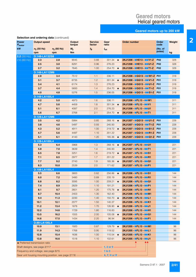
Geared motorsHelical geared motors
Geared motors up to 200 kW
2/41Siemens D 87.1 · 2007
2
2.2 (50 Hz) D.148-LA132S82.6 (60 Hz) 2.3 2.8 9045 0.88 301.34 � 2KJ1208 - 7HE13 - 77V1-Z P02 328
2.5 3.0 8291 0.96 276.23 2KJ1208 - 7HE13 - 77U1-Z P02 328
2.7 3.2 7645 1.00 254.70 � 2KJ1208 - 7HE13 - 77T1-Z P02 328
D.148-LA112M62.8 3.4 7512 1.1 336.11 2KJ1208 - 7GG13 - 77W1-Z P01 318
3.1 3.7 6735 1.2 301.34 � 2KJ1208 - 7GG13 - 77V1-Z P01 318
3.4 4.1 6174 1.3 276.23 2KJ1208 - 7GG13 - 77U1-Z P01 318
3.7 4.4 5693 1.4 254.70 � 2KJ1208 - 7GG13 - 77T1-Z P01 318
4.0 4.8 5276 1.5 236.05 2KJ1208 - 7GG13 - 77S1-Z P01 318
D.148-LA100L44.2 5.0 4973 1.6 336.11 2KJ1208 - 7FL13 - 77W1 311
4.7 5.6 4459 1.8 301.34 � 2KJ1208 - 7FL13 - 77V1 311
5.1 6.1 4087 2.0 276.23 2KJ1208 - 7FL13 - 77U1 311
5.6 6.7 3768 2.1 254.70 � 2KJ1208 - 7FL13 - 77T1 311
D.128-LA112M63.5 4.2 5994 0.85 268.16 � 2KJ1207 - 7GG13 - 77U1-Z P01 228
3.8 4.6 5497 0.93 245.93 2KJ1207 - 7GG13 - 77T1-Z P01 228
4.3 5.2 4911 1.00 219.72 � 2KJ1207 - 7GG13 - 77S1-Z P01 228
4.7 5.6 4497 1.10 201.22 2KJ1207 - 7GG13 - 77R1-Z P01 228
5.1 6.1 4143 1.20 185.36 � 2KJ1207 - 7GG13 - 77Q1-Z P01 228
D.128-LA100L45.3 6.4 3968 1.3 268.16 � 2KJ1207 - 7FL13 - 77U1 221
5.8 7.0 3639 1.4 245.93 2KJ1207 - 7FL13 - 77T1 221
6.5 7.8 3251 1.6 219.72 � 2KJ1207 - 7FL13 - 77S1 221
7.1 8.5 2977 1.7 201.22 2KJ1207 - 7FL13 - 77R1 221
7.7 9.2 2743 1.9 185.36 � 2KJ1207 - 7FL13 - 77Q1 221
8.3 10.0 2539 2.0 171.62 2KJ1207 - 7FL13 - 77P1 221
D.108-LA100L45.5 6.6 3800 0.82 256.86 � 2KJ1206 - 7FL13 - 77S1 144
6.0 7.2 3480 0.89 235.19 2KJ1206 - 7FL13 - 77R1 144
6.8 8.2 3095 1.00 209.21 � 2KJ1206 - 7FL13 - 77Q1 144
7.4 8.9 2829 1.10 191.21 2KJ1206 - 7FL13 - 77P1 144
8.1 9.7 2601 1.20 175.78 � 2KJ1206 - 7FL13 - 77N1 144
8.7 10.4 2403 1.30 162.40 2KJ1206 - 7FL13 - 77M1 144
9.4 11.3 2230 1.40 150.70 � 2KJ1206 - 7FL13 - 77L1 144
10.1 12.1 2077 1.50 140.37 2KJ1206 - 7FL13 - 77K1 144
11.2 13.4 1878 1.70 126.90 � 2KJ1206 - 7FL13 - 77J1 144
12.2 14.6 1729 1.80 116.83 2KJ1206 - 7FL13 - 77H1 144
13.5 16.2 1555 2.00 105.08 � 2KJ1206 - 7FL13 - 77G1 144
14.6 17.5 1434 2.20 96.94 2KJ1206 - 7FL13 - 77F1 144
D.88-LA100L410.9 13.1 1920 0.87 129.79 � 2KJ1205 - 7FL13 - 77M1 96
11.9 14.3 1768 0.95 119.52 2KJ1205 - 7FL13 - 77L1 96
12.8 15.4 1636 1.00 110.54 � 2KJ1205 - 7FL13 - 77K1 96
13.8 16.6 1518 1.10 102.61 2KJ1205 - 7FL13 - 77J1 96
Selection and ordering data (continued)
PowerPmotor
Output speed Output torque
Service factor
Gear ratio
Order number Order code
Weight
kW n2 (50 Hz) n2 (60 Hz) M2 fB itot (No. of poles)rpm rpm Nm kg
� Preferred transmission ratio
Shaft designs, see page 2/117 –––––––––––––––––––––––––––––––––––––––––– 1, 2 or 9 –––––––––––––––––––
Frequency and voltage, see page 8/15 ––––––––––––––––––––––––––––––––––– 1 to 9 ––––––––––––––––––––––––––––––
Gear unit housing mounting position, see page 2/116 –––––––––––––––––––––– A, F, H or R ––––––––––––––––––––––––––

Geared motorsHelical geared motors
Geared motors up to 200 kW
2/42 Siemens D 87.1 · 2007
2
2.2 (50 Hz) D.88-LA100L42.6 (60 Hz) 15.7 18.8 1339 1.3 90.53 � 2KJ1205 - 7FL13 - 77H1 96
17.0 20.0 1237 1.4 83.58 2KJ1205 - 7FL13 - 77G1 96
19.0 23.0 1108 1.5 74.88 � 2KJ1205 - 7FL13 - 77F1 96
21.0 25.0 1022 1.6 69.05 2KJ1205 - 7FL13 - 77E1 96
24.0 29.0 857 2.0 57.93 2KJ1205 - 7FL13 - 77D1 96
28.0 34.0 751 2.0 50.73 2KJ1105 - 7FL13 - 77B2 94
31.0 37.0 677 2.5 45.76 � 2KJ1105 - 7FL13 - 77A2 94
D.68-LA100L421 25 993 0.81 67.14 2KJ1204 - 7FL13 - 77E1 64
24 29 886 0.90 59.91 � 2KJ1204 - 7FL13 - 77D1 64
27 32 791 1.00 53.47 2KJ1204 - 7FL13 - 77C1 64
Z.68-LA100L434 41 622 1.3 42.06 2KJ1104 - 7FL13 - 77W1 62
38 46 559 1.4 37.76 � 2KJ1104 - 7FL13 - 77V1 62
41 49 510 1.6 34.49 2KJ1104 - 7FL13 - 77U1 62
46 55 453 1.8 30.60 � 2KJ1104 - 7FL13 - 77T1 62
50 60 418 1.9 28.25 2KJ1104 - 7FL13 - 77S1 62
56 67 378 2.1 25.55 � 2KJ1104 - 7FL13 - 77R1 62
60 72 348 2.3 23.53 2KJ1104 - 7FL13 - 77Q1 62
65 78 322 2.5 21.76 � 2KJ1104 - 7FL13 - 77P1 62
70 84 299 2.7 20.20 2KJ1104 - 7FL13 - 77N1 62
80 96 264 3.0 17.82 � 2KJ1104 - 7FL13 - 77M1 62
86 103 243 3.3 16.45 2KJ1104 - 7FL13 - 77L1 62
D.48-LA100L440 48 527 0.85 35.59 2KJ1203 - 7FL13 - 77A1 45
Z.48-LA100L445 54 470 0.96 31.77 2KJ1103 - 7FL13 - 77U1 45
49 59 425 1.10 28.74 � 2KJ1103 - 7FL13 - 77T1 45
54 65 393 1.10 26.53 2KJ1103 - 7FL13 - 77S1 45
62 74 341 1.30 23.07 � 2KJ1103 - 7FL13 - 77R1 45
68 82 310 1.50 20.95 2KJ1103 - 7FL13 - 77Q1 45
74 89 283 1.60 19.13 � 2KJ1103 - 7FL13 - 77P1 45
81 97 260 1.70 17.55 2KJ1103 - 7FL13 - 77N1 45
88 106 239 1.80 16.17 � 2KJ1103 - 7FL13 - 77M1 45
97 116 217 1.90 14.68 2KJ1103 - 7FL13 - 77L1 45
106 127 198 2.10 13.38 � 2KJ1103 - 7FL13 - 77K1 45
116 139 181 2.20 12.25 2KJ1103 - 7FL13 - 77J1 45
130 156 162 2.40 10.93 � 2KJ1103 - 7FL13 - 77H1 45
145 174 144 2.60 9.76 2KJ1103 - 7FL13 - 77G1 45
171 205 123 2.90 8.29 2KJ1103 - 7FL13 - 77F1 45
206 247 102 3.30 6.90 � 2KJ1103 - 7FL13 - 77E1 45
209 251 100 2.70 6.79 � 2KJ1103 - 7FL13 - 77D1 45
234 281 90 3.00 6.06 2KJ1103 - 7FL13 - 77C1 45
Selection and ordering data (continued)
PowerPmotor
Output speed Output torque
Service factor
Gear ratio
Order number Order code
Weight
kW n2 (50 Hz) n2 (60 Hz) M2 fB itot (No. of poles)rpm rpm Nm kg
� Preferred transmission ratio
Shaft designs, see page 2/117 –––––––––––––––––––––––––––––––––––––––––– 1, 2 or 9 –––––––––––––––––––
Frequency and voltage, see page 8/15 ––––––––––––––––––––––––––––––––––– 1 to 9 ––––––––––––––––––––––––––––––
Gear unit housing mounting position, see page 2/116 –––––––––––––––––––––– A, F, H or R ––––––––––––––––––––––––––

Geared motorsHelical geared motors
Geared motors up to 200 kW
2/43Siemens D 87.1 · 2007
2
2.2 (50 Hz) Z.48-LA100L42.6 (60 Hz) 276 331 76 3.5 5.15 2KJ1103 - 7FL13 - 77B1 45
332 398 63 4.1 4.28 � 2KJ1103 - 7FL13 - 77A1 45
Z.38-LA100L482 98 256 0.86 17.33 � 2KJ1102 - 7FL13 - 77Q1 35
91 109 231 0.95 15.64 2KJ1102 - 7FL13 - 77P1 35
100 120 210 1.00 14.18 � 2KJ1102 - 7FL13 - 77N1 35
110 132 191 1.20 12.92 2KJ1102 - 7FL13 - 77M1 35
120 144 175 1.30 11.82 � 2KJ1102 - 7FL13 - 77L1 35
134 161 156 1.30 10.57 2KJ1102 - 7FL13 - 77K1 35
146 175 144 1.40 9.70 � 2KJ1102 - 7FL13 - 77J1 35
162 194 129 1.50 8.75 2KJ1102 - 7FL13 - 77H1 35
189 227 111 1.70 7.50 � 2KJ1102 - 7FL13 - 77F1 35
189 227 111 1.70 7.52 � 2KJ1102 - 7FL13 - 77G1 35
212 254 99 1.80 6.71 2KJ1102 - 7FL13 - 77D1 35
231 277 91 1.90 6.16 � 2KJ1102 - 7FL13 - 77C1 35
256 307 82 2.00 5.55 2KJ1102 - 7FL13 - 77B1 35
298 358 71 2.30 4.77 � 2KJ1102 - 7FL13 - 77A1 35
Z.28-LA90ZLB4128 154 164 0.85 10.87 � 2KJ1101 - 7EQ13 - 77M1 20
145 174 145 0.96 9.61 2KJ1101 - 7EQ13 - 77L1 20
157 188 134 1.00 8.87 � 2KJ1101 - 7EQ13 - 77K1 20
182 218 115 1.20 7.64 2KJ1101 - 7EQ13 - 77J1 20
200 240 105 1.30 6.94 � 2KJ1101 - 7EQ13 - 77H1 20
220 264 95 1.00 6.31 � 2KJ1101 - 7EQ13 - 77G1 20
243 292 86 1.10 5.72 2KJ1101 - 7EQ13 - 77F1 20
267 320 79 1.20 5.21 � 2KJ1101 - 7EQ13 - 77E1 20
302 362 70 1.30 4.60 2KJ1101 - 7EQ13 - 77D1 20
327 392 64 1.40 4.25 � 2KJ1101 - 7EQ13 - 77C1 20
380 456 55 1.40 3.66 2KJ1101 - 7EQ13 - 77B1 20
417 500 50 1.50 3.33 � 2KJ1101 - 7EQ13 - 77A1 20
E.128-LA100L4140 168 150 3.6 10.14 � 2KJ1006 - 7FL13 - 77T1 119
E.88-LA100L4137 164 153 1.5 10.33 � 2KJ1004 - 7FL13 - 77S1 61
150 180 140 1.5 9.46 2KJ1004 - 7FL13 - 77R1 61
169 203 125 2.0 8.42 � 2KJ1004 - 7FL13 - 77Q1 61
185 222 114 2.2 7.69 2KJ1004 - 7FL13 - 77P1 61
201 241 105 2.8 7.07 � 2KJ1004 - 7FL13 - 77N1 61
217 260 97 3.1 6.53 2KJ1004 - 7FL13 - 77M1 61
234 281 90 3.1 6.06 � 2KJ1004 - 7FL13 - 77L1 61
251 301 84 3.8 5.65 2KJ1004 - 7FL13 - 77K1 61
278 334 76 4.9 5.11 � 2KJ1004 - 7FL13 - 77J1 61
E.68-LA100L4161 193 130 1.1 8.82 2KJ1003 - 7FL13 - 77T1 44
179 215 117 1.5 7.92 � 2KJ1003 - 7FL13 - 77S1 44
Selection and ordering data (continued)
PowerPmotor
Output speed Output torque
Service factor
Gear ratio
Order number Order code
Weight
kW n2 (50 Hz) n2 (60 Hz) M2 fB itot (No. of poles)rpm rpm Nm kg
� Preferred transmission ratio
Shaft designs, see page 2/117 –––––––––––––––––––––––––––––––––––––––––– 1, 2 or 9 –––––––––––––––––––
Frequency and voltage, see page 8/15 ––––––––––––––––––––––––––––––––––– 1 to 9 ––––––––––––––––––––––––––––––
Gear unit housing mounting position, see page 2/116 –––––––––––––––––––––– A, F, H or R ––––––––––––––––––––––––––

Geared motorsHelical geared motors
Geared motors up to 200 kW
2/44 Siemens D 87.1 · 2007
2
2.2 (50 Hz) E.68-LA100L42.6 (60 Hz) 196 235 107 1.4 7.23 2KJ1003 - 7FL13 - 77R1 44
221 265 95 1.8 6.42 � 2KJ1003 - 7FL13 - 77P1 44
240 288 88 2.2 5.92 2KJ1003 - 7FL13 - 77N1 44
265 318 79 2.8 5.36 � 2KJ1003 - 7FL13 - 77M1 44
288 346 73 3.1 4.93 2KJ1003 - 7FL13 - 77L1 44
311 373 68 3.3 4.56 � 2KJ1003 - 7FL13 - 77K1 44
335 402 63 3.7 4.24 2KJ1003 - 7FL13 - 77J1 44
380 456 55 4.2 3.74 � 2KJ1003 - 7FL13 - 77H1 44
412 494 51 4.7 3.45 2KJ1003 - 7FL13 - 77G1 44
460 552 46 5.5 3.09 � 2KJ1003 - 7FL13 - 77F1 44
E.48-LA100L4203 244 104 0.94 7.00 2KJ1002 - 7FL13 - 77Q1 34
224 269 94 1.20 6.33 � 2KJ1002 - 7FL13 - 77P1 34
243 292 87 1.40 5.85 2KJ1002 - 7FL13 - 77N1 34
280 336 75 1.60 5.08 � 2KJ1002 - 7FL13 - 77M1 34
307 368 68 1.90 4.62 2KJ1002 - 7FL13 - 77L1 34
337 404 62 2.40 4.21 � 2KJ1002 - 7FL13 - 77K1 34
367 440 57 2.80 3.87 2KJ1002 - 7FL13 - 77J1 34
399 479 53 2.70 3.56 � 2KJ1002 - 7FL13 - 77H1 34
438 526 48 3.10 3.24 2KJ1002 - 7FL13 - 77G1 34
481 577 44 3.90 2.95 � 2KJ1002 - 7FL13 - 77F1 34
526 631 40 4.00 2.70 2KJ1002 - 7FL13 - 77E1 34
589 707 36 4.20 2.41 � 2KJ1002 - 7FL13 - 77D1 34
660 792 32 4.20 2.15 2KJ1002 - 7FL13 - 77C1 34
776 931 27 4.20 1.83 2KJ1002 - 7FL13 - 77B1 34
934 1121 22 4.40 1.52 � 2KJ1002 - 7FL13 - 77A1 34
E.38-LA100L4274 329 77 0.91 5.18 2KJ1001 - 7FL13 - 77M1 31
310 372 68 1.20 4.58 � 2KJ1001 - 7FL13 - 77L1 31
342 410 61 1.00 4.15 2KJ1001 - 7FL13 - 77K1 31
387 464 54 1.30 3.67 � 2KJ1001 - 7FL13 - 77J1 31
429 515 49 1.30 3.31 2KJ1001 - 7FL13 - 77H1 31
473 568 44 1.80 3.00 � 2KJ1001 - 7FL13 - 77G1 31
520 624 40 2.00 2.73 2KJ1001 - 7FL13 - 77F1 31
568 682 37 2.00 2.50 � 2KJ1001 - 7FL13 - 77E1 31
634 761 33 2.20 2.24 2KJ1001 - 7FL13 - 77D1 31
693 832 30 2.60 2.05 � 2KJ1001 - 7FL13 - 77C1 31
768 922 27 3.00 1.85 2KJ1001 - 7FL13 - 77B1 31
893 1072 24 3.10 1.59 � 2KJ1001 - 7FL13 - 77A1 31
3.0 (50 Hz) D.188-Z68-LA100LB43.6 (60 Hz) 1.1 1.3 23239 0.86 1251 2KJ1237 - 7FM13 - 77J1 638
1.4 1.7 19505 1.00 1050 2KJ1237 - 7FM13 - 77H1 638
1.6 1.9 16644 1.20 896 � 2KJ1237 - 7FM13 - 77G1 638
Selection and ordering data (continued)
PowerPmotor
Output speed Output torque
Service factor
Gear ratio
Order number Order code
Weight
kW n2 (50 Hz) n2 (60 Hz) M2 fB itot (No. of poles)rpm rpm Nm kg
� Preferred transmission ratio
Shaft designs, see page 2/117 –––––––––––––––––––––––––––––––––––––––––– 1, 2 or 9 –––––––––––––––––––
Frequency and voltage, see page 8/15 ––––––––––––––––––––––––––––––––––– 1 to 9 ––––––––––––––––––––––––––––––
Gear unit housing mounting position, see page 2/116 –––––––––––––––––––––– A, F, H or R ––––––––––––––––––––––––––

Geared motorsHelical geared motors
Geared motors up to 200 kW
2/45Siemens D 87.1 · 2007
2
3.0 (50 Hz) D.188-Z68-LA100LB43.6 (60 Hz) 1.9 2.3 13858 1.4 746 2KJ1237 - 7FM13 - 77F1 638
2.3 2.8 11499 1.7 619 � 2KJ1237 - 7FM13 - 77E1 638
2.6 3.1 10143 2.0 546 2KJ1237 - 7FM13 - 77D1 638
D.188-Z48-LA100LB41.1 1.3 23313 0.86 1255 2KJ1235 - 7FM13 - 77B1 621
1.4 1.7 19393 1.00 1044 � 2KJ1235 - 7FM13 - 77A1 621
D.188-LA132MA82.9 3.5 9979 2.0 243.82 2KJ1211 - 7HG13 - 77N1-Z P02 652
D.168-Z68-LA100LB41.6 1.9 16180 0.87 871 2KJ1233 - 7FM13 - 77F1 494
D.168-LA132MA82.0 2.4 13982 1.0 341.61 � 2KJ1210 - 7HG13 - 77U1-Z P02 507
2.2 2.6 12827 1.1 313.41 2KJ1210 - 7HG13 - 77T1-Z P02 507
2.4 2.9 11838 1.2 289.23 � 2KJ1210 - 7HG13 - 77S1-Z P02 507
2.6 3.1 10981 1.3 268.29 2KJ1210 - 7HG13 - 77R1-Z P02 507
D.168-LA132S62.8 3.4 10302 1.4 341.61 � 2KJ1210 - 7HE13 - 77U1-Z P01 499
3.0 3.6 9452 1.5 313.41 2KJ1210 - 7HE13 - 77T1-Z P01 499
3.3 4.0 8723 1.6 289.23 � 2KJ1210 - 7HE13 - 77S1-Z P01 499
3.5 4.2 8091 1.7 268.29 2KJ1210 - 7HE13 - 77R1-Z P01 499
3.8 4.6 7632 1.8 253.08 � 2KJ1210 - 7HE13 - 77Q1-Z P01 499
4.0 4.8 7139 2.0 236.72 2KJ1210 - 7HE13 - 77P1-Z P01 499
D.148-LA132S63.2 3.8 9088 0.88 301.34 � 2KJ1208 - 7HE13 - 77V1-Z P01 328
3.4 4.1 8331 0.96 276.23 2KJ1208 - 7HE13 - 77U1-Z P01 328
3.7 4.4 7681 1.00 254.70 � 2KJ1208 - 7HE13 - 77T1-Z P01 328
4.0 4.8 7119 1.10 236.05 2KJ1208 - 7HE13 - 77S1-Z P01 328
D.148-LA100LB44.2 5.0 6781 1.2 336.11 2KJ1208 - 7FM13 - 77W1 311
4.7 5.6 6080 1.3 301.34 � 2KJ1208 - 7FM13 - 77V1 311
5.1 6.1 5573 1.4 276.23 2KJ1208 - 7FM13 - 77U1 311
5.6 6.7 5139 1.6 254.70 � 2KJ1208 - 7FM13 - 77T1 311
6.0 7.2 4763 1.7 236.05 2KJ1208 - 7FM13 - 77S1 311
6.3 7.6 4528 1.8 224.43 � 2KJ1208 - 7FM13 - 77R1 311
6.8 8.2 4232 1.9 209.76 2KJ1208 - 7FM13 - 77Q1 311
7.7 9.2 3733 2.1 185.03 � 2KJ1208 - 7FM13 - 77P1 311
D.128-LA132S64.7 5.6 6068 0.84 201.22 2KJ1207 - 7HE13 - 77R1-Z P01 238
5.1 6.1 5590 0.91 185.36 � 2KJ1207 - 7HE13 - 77Q1-Z P01 238
D.128-LA100LB45.3 6.4 5410 0.94 268.16 � 2KJ1207 - 7FM13 - 77U1 221
5.8 7.0 4962 1.00 245.93 2KJ1207 - 7FM13 - 77T1 221
6.5 7.8 4433 1.20 219.72 � 2KJ1207 - 7FM13 - 77S1 221
7.1 8.5 4060 1.30 201.22 2KJ1207 - 7FM13 - 77R1 221
7.7 9.2 3740 1.40 185.36 � 2KJ1207 - 7FM13 - 77Q1 221
Selection and ordering data (continued)
PowerPmotor
Output speed Output torque
Service factor
Gear ratio
Order number Order code
Weight
kW n2 (50 Hz) n2 (60 Hz) M2 fB itot (No. of poles)rpm rpm Nm kg
� Preferred transmission ratio
Shaft designs, see page 2/117 –––––––––––––––––––––––––––––––––––––––––– 1, 2 or 9 –––––––––––––––––––
Frequency and voltage, see page 8/15 ––––––––––––––––––––––––––––––––––– 1 to 9 ––––––––––––––––––––––––––––––
Gear unit housing mounting position, see page 2/116 –––––––––––––––––––––– A, F, H or R ––––––––––––––––––––––––––

Geared motorsHelical geared motors
Geared motors up to 200 kW
2/46 Siemens D 87.1 · 2007
2
3.0 (50 Hz) D.128-LA100LB43.6 (60 Hz) 8.3 10.0 3463 1.5 171.62 2KJ1207 - 7FM13 - 77P1 221
8.9 10.7 3220 1.6 159.60 � 2KJ1207 - 7FM13 - 77N1 221
9.5 11.4 3006 1.7 148.99 2KJ1207 - 7FM13 - 77M1 221
10.7 12.8 2689 1.9 133.30 � 2KJ1207 - 7FM13 - 77L1 221
11.5 13.8 2492 2.0 123.53 2KJ1207 - 7FM13 - 77K1 221
12.5 15.0 2285 2.2 113.24 � 2KJ1207 - 7FM13 - 77J1 221
D.108-LA100LB47.4 8.9 3858 0.80 191.21 2KJ1206 - 7FM13 - 77P1 144
8.1 9.7 3547 0.87 175.78 � 2KJ1206 - 7FM13 - 77N1 144
8.7 10.4 3277 0.95 162.40 2KJ1206 - 7FM13 - 77M1 144
9.4 11.3 3041 1.00 150.70 � 2KJ1206 - 7FM13 - 77L1 144
10.1 12.1 2832 1.10 140.37 2KJ1206 - 7FM13 - 77K1 144
11.2 13.4 2560 1.20 126.90 � 2KJ1206 - 7FM13 - 77J1 144
12.2 14.6 2357 1.30 116.83 2KJ1206 - 7FM13 - 77H1 144
13.5 16.2 2120 1.50 105.08 � 2KJ1206 - 7FM13 - 77G1 144
14.6 17.5 1956 1.60 96.94 2KJ1206 - 7FM13 - 77F1 144
17.3 21.0 1657 1.90 82.14 2KJ1206 - 7FM13 - 77E1 144
19.8 24.0 1444 2.10 71.59 � 2KJ1206 - 7FM13 - 77D1 144
Z.108-LA100LB424 29 1191 2.0 59.05 � 2KJ1106 - 7FM13 - 77E2 140
26 31 1093 2.1 54.15 2KJ1106 - 7FM13 - 77D2 140
D.88-LA100LB413.8 16.6 2070 0.81 102.61 2KJ1205 - 7FM13 - 77J1 96
15.7 18.8 1827 0.92 90.53 � 2KJ1205 - 7FM13 - 77H1 96
17.0 20.0 1686 1.00 83.58 2KJ1205 - 7FM13 - 77G1 96
19.0 23.0 1511 1.10 74.88 � 2KJ1205 - 7FM13 - 77F1 96
21.0 25.0 1393 1.20 69.05 2KJ1205 - 7FM13 - 77E1 96
24.0 29.0 1169 1.40 57.93 2KJ1205 - 7FM13 - 77D1 96
Z.88-LA100LB428 34 1024 1.4 50.73 2KJ1105 - 7FM13 - 77B2 94
31 37 923 1.8 45.76 � 2KJ1105 - 7FM13 - 77A2 94
34 41 845 2.0 41.90 2KJ1105 - 7FM13 - 77X1 94
38 46 752 2.2 37.27 � 2KJ1105 - 7FM13 - 77W1 94
42 50 687 2.4 34.07 2KJ1105 - 7FM13 - 77V1 94
45 54 632 2.7 31.32 � 2KJ1105 - 7FM13 - 77U1 94
Z.68-LA100LB434 41 849 0.94 42.06 2KJ1104 - 7FM13 - 77W1 62
38 46 762 1.10 37.76 � 2KJ1104 - 7FM13 - 77V1 62
41 49 696 1.10 34.49 2KJ1104 - 7FM13 - 77U1 62
46 55 617 1.30 30.60 � 2KJ1104 - 7FM13 - 77T1 62
50 60 570 1.40 28.25 2KJ1104 - 7FM13 - 77S1 62
56 67 515 1.60 25.55 � 2KJ1104 - 7FM13 - 77R1 62
60 72 475 1.70 23.53 2KJ1104 - 7FM13 - 77Q1 62
65 78 439 1.80 21.76 � 2KJ1104 - 7FM13 - 77P1 62
70 84 408 2.00 20.20 2KJ1104 - 7FM13 - 77N1 62
Selection and ordering data (continued)
PowerPmotor
Output speed Output torque
Service factor
Gear ratio
Order number Order code
Weight
kW n2 (50 Hz) n2 (60 Hz) M2 fB itot (No. of poles)rpm rpm Nm kg
� Preferred transmission ratio
Shaft designs, see page 2/117 –––––––––––––––––––––––––––––––––––––––––– 1, 2 or 9 –––––––––––––––––––
Frequency and voltage, see page 8/15 ––––––––––––––––––––––––––––––––––– 1 to 9 ––––––––––––––––––––––––––––––
Gear unit housing mounting position, see page 2/116 –––––––––––––––––––––– A, F, H or R ––––––––––––––––––––––––––

Geared motorsHelical geared motors
Geared motors up to 200 kW
2/47Siemens D 87.1 · 2007
2
3.0 (50 Hz) Z.68-LA100LB43.6 (60 Hz) 80 96 360 2.2 17.82 � 2KJ1104 - 7FM13 - 77M1 62
86 103 332 2.4 16.45 2KJ1104 - 7FM13 - 77L1 62
96 115 297 2.7 14.74 � 2KJ1104 - 7FM13 - 77K1 62
104 125 274 2.9 13.59 2KJ1104 - 7FM13 - 77J1 62
125 150 230 3.4 11.40 2KJ1104 - 7FM13 - 77H1 62
146 175 196 3.8 9.73 � 2KJ1104 - 7FM13 - 77G1 62
239 287 120 4.1 5.93 2KJ1104 - 7FM13 - 77D1 62
281 337 102 4.7 5.06 � 2KJ1104 - 7FM13 - 77C1 62
Z.48-LA100LB454 65 535 0.84 26.53 2KJ1103 - 7FM13 - 77S1 45
62 74 465 0.97 23.07 � 2KJ1103 - 7FM13 - 77R1 45
68 82 423 1.10 20.95 2KJ1103 - 7FM13 - 77Q1 45
74 89 386 1.20 19.13 � 2KJ1103 - 7FM13 - 77P1 45
81 97 354 1.30 17.55 2KJ1103 - 7FM13 - 77N1 45
88 106 326 1.30 16.17 � 2KJ1103 - 7FM13 - 77M1 45
97 116 296 1.40 14.68 2KJ1103 - 7FM13 - 77L1 45
106 127 270 1.50 13.38 � 2KJ1103 - 7FM13 - 77K1 45
116 139 247 1.60 12.25 2KJ1103 - 7FM13 - 77J1 45
130 156 221 1.80 10.93 � 2KJ1103 - 7FM13 - 77H1 45
145 174 197 1.90 9.76 2KJ1103 - 7FM13 - 77G1 45
171 205 167 2.20 8.29 2KJ1103 - 7FM13 - 77F1 45
206 247 139 2.40 6.90 � 2KJ1103 - 7FM13 - 77E1 45
209 251 137 2.00 6.79 � 2KJ1103 - 7FM13 - 77D1 45
234 281 122 2.20 6.06 2KJ1103 - 7FM13 - 77C1 45
276 331 104 2.60 5.15 2KJ1103 - 7FM13 - 77B1 45
332 398 86 3.00 4.28 � 2KJ1103 - 7FM13 - 77A1 45
Z.38-LA100LB4110 132 261 0.84 12.92 2KJ1102 - 7FM13 - 77M1 35
120 144 238 0.92 11.82 � 2KJ1102 - 7FM13 - 77L1 35
134 161 213 0.98 10.57 2KJ1102 - 7FM13 - 77K1 35
146 175 196 1.00 9.70 � 2KJ1102 - 7FM13 - 77J1 35
162 194 177 1.10 8.75 2KJ1102 - 7FM13 - 77H1 35
189 227 151 1.20 7.50 � 2KJ1102 - 7FM13 - 77F1 35
189 227 152 1.30 7.52 � 2KJ1102 - 7FM13 - 77G1 35
212 254 135 1.30 6.71 2KJ1102 - 7FM13 - 77D1 35
231 277 124 1.40 6.16 � 2KJ1102 - 7FM13 - 77C1 35
256 307 112 1.50 5.55 2KJ1102 - 7FM13 - 77B1 35
298 358 96 1.70 4.77 � 2KJ1102 - 7FM13 - 77A1 35
Z.28-LA100LB4186 223 154 0.88 7.64 2KJ1101 - 7FM13 - 77J1 28
205 246 140 0.94 6.94 � 2KJ1101 - 7FM13 - 77H1 28
248 298 115 0.81 5.72 2KJ1101 - 7FM13 - 77F1 28
273 328 105 0.88 5.21 � 2KJ1101 - 7FM13 - 77E1 28
309 371 93 0.95 4.60 2KJ1101 - 7FM13 - 77D1 28
334 401 86 1.00 4.25 � 2KJ1101 - 7FM13 - 77C1 28
Selection and ordering data (continued)
PowerPmotor
Output speed Output torque
Service factor
Gear ratio
Order number Order code
Weight
kW n2 (50 Hz) n2 (60 Hz) M2 fB itot (No. of poles)rpm rpm Nm kg
� Preferred transmission ratio
Shaft designs, see page 2/117 –––––––––––––––––––––––––––––––––––––––––– 1, 2 or 9 –––––––––––––––––––
Frequency and voltage, see page 8/15 ––––––––––––––––––––––––––––––––––– 1 to 9 ––––––––––––––––––––––––––––––
Gear unit housing mounting position, see page 2/116 –––––––––––––––––––––– A, F, H or R ––––––––––––––––––––––––––

Geared motorsHelical geared motors
Geared motors up to 200 kW
2/48 Siemens D 87.1 · 2007
2
3.0 (50 Hz) Z.28-LA100LB43.6 (60 Hz) 388 466 74 1.1 3.66 2KJ1101 - 7FM13 - 77B1 28
426 511 67 1.1 3.33 � 2KJ1101 - 7FM13 - 77A1 28
E.128-LA100LB4140 168 205 2.7 10.14 � 2KJ1006 - 7FM13 - 77T1 119
151 181 190 3.1 9.40 2KJ1006 - 7FM13 - 77S1 119
159 191 180 3.5 8.94 � 2KJ1006 - 7FM13 - 77R1 119
170 204 168 4.2 8.35 2KJ1006 - 7FM13 - 77Q1 119
E.88-LA100LB4137 164 208 1.1 10.33 � 2KJ1004 - 7FM13 - 77S1 61
150 180 191 1.1 9.46 2KJ1004 - 7FM13 - 77R1 61
169 203 170 1.4 8.42 � 2KJ1004 - 7FM13 - 77Q1 61
185 222 155 1.6 7.69 2KJ1004 - 7FM13 - 77P1 61
201 241 143 2.0 7.07 � 2KJ1004 - 7FM13 - 77N1 61
217 260 132 2.3 6.53 2KJ1004 - 7FM13 - 77M1 61
234 281 122 2.3 6.06 � 2KJ1004 - 7FM13 - 77L1 61
251 301 114 2.8 5.65 2KJ1004 - 7FM13 - 77K1 61
278 334 103 3.6 5.11 � 2KJ1004 - 7FM13 - 77J1 61
302 362 95 4.1 4.70 2KJ1004 - 7FM13 - 77H1 61
336 403 85 4.7 4.23 � 2KJ1004 - 7FM13 - 77G1 61
364 437 79 4.9 3.90 2KJ1004 - 7FM13 - 77F1 61
E.68-LA100LB4161 193 178 0.84 8.82 2KJ1003 - 7FM13 - 77T1 44
179 215 160 1.10 7.92 � 2KJ1003 - 7FM13 - 77S1 44
196 235 146 1.00 7.23 2KJ1003 - 7FM13 - 77R1 44
221 265 130 1.30 6.42 � 2KJ1003 - 7FM13 - 77P1 44
240 288 119 1.60 5.92 2KJ1003 - 7FM13 - 77N1 44
265 318 108 2.00 5.36 � 2KJ1003 - 7FM13 - 77M1 44
288 346 100 2.30 4.93 2KJ1003 - 7FM13 - 77L1 44
311 373 92 2.40 4.56 � 2KJ1003 - 7FM13 - 77K1 44
335 402 86 2.70 4.24 2KJ1003 - 7FM13 - 77J1 44
380 456 76 3.00 3.74 � 2KJ1003 - 7FM13 - 77H1 44
412 494 70 3.40 3.45 2KJ1003 - 7FM13 - 77G1 44
460 552 62 4.00 3.09 � 2KJ1003 - 7FM13 - 77F1 44
498 598 58 4.30 2.85 2KJ1003 - 7FM13 - 77E1 44
594 713 48 4.80 2.39 2KJ1003 - 7FM13 - 77D1 44
696 835 41 5.10 2.04 � 2KJ1003 - 7FM13 - 77C1 44
835 1002 34 5.10 1.70 2KJ1003 - 7FM13 - 77B1 44
1007 1208 28 5.30 1.41 � 2KJ1003 - 7FM13 - 77A1 44
E.48-LA100LB4224 269 128 0.9 6.33 � 2KJ1002 - 7FM13 - 77P1 34
243 292 118 1.0 5.85 2KJ1002 - 7FM13 - 77N1 34
280 336 102 1.2 5.08 � 2KJ1002 - 7FM13 - 77M1 34
307 368 93 1.4 4.62 2KJ1002 - 7FM13 - 77L1 34
337 404 85 1.8 4.21 � 2KJ1002 - 7FM13 - 77K1 34
367 440 78 2.0 3.87 2KJ1002 - 7FM13 - 77J1 34
Selection and ordering data (continued)
PowerPmotor
Output speed Output torque
Service factor
Gear ratio
Order number Order code
Weight
kW n2 (50 Hz) n2 (60 Hz) M2 fB itot (No. of poles)rpm rpm Nm kg
� Preferred transmission ratio
Shaft designs, see page 2/117 –––––––––––––––––––––––––––––––––––––––––– 1, 2 or 9 –––––––––––––––––––
Frequency and voltage, see page 8/15 ––––––––––––––––––––––––––––––––––– 1 to 9 ––––––––––––––––––––––––––––––
Gear unit housing mounting position, see page 2/116 –––––––––––––––––––––– A, F, H or R ––––––––––––––––––––––––––

Geared motorsHelical geared motors
Geared motors up to 200 kW
2/49Siemens D 87.1 · 2007
2
3.0 (50 Hz) E.48-LA100LB43.6 (60 Hz) 399 479 72 1.9 3.56 � 2KJ1002 - 7FM13 - 77H1 34
438 526 65 2.3 3.24 2KJ1002 - 7FM13 - 77G1 34
481 577 60 2.9 2.95 � 2KJ1002 - 7FM13 - 77F1 34
526 631 54 2.9 2.70 2KJ1002 - 7FM13 - 77E1 34
589 707 49 3.1 2.41 � 2KJ1002 - 7FM13 - 77D1 34
660 792 43 3.1 2.15 2KJ1002 - 7FM13 - 77C1 34
776 931 37 3.1 1.83 2KJ1002 - 7FM13 - 77B1 34
934 1121 31 3.3 1.52 � 2KJ1002 - 7FM13 - 77A1 34
E.38-LA100LB4310 372 92 0.84 4.58 � 2KJ1001 - 7FM13 - 77L1 31
387 464 74 0.95 3.67 � 2KJ1001 - 7FM13 - 77J1 31
429 515 67 0.97 3.31 2KJ1001 - 7FM13 - 77H1 31
473 568 60 1.30 3.00 � 2KJ1001 - 7FM13 - 77G1 31
520 624 55 1.50 2.73 2KJ1001 - 7FM13 - 77F1 31
634 761 45 1.60 2.24 2KJ1001 - 7FM13 - 77D1 31
693 832 41 1.90 2.05 � 2KJ1001 - 7FM13 - 77C1 31
768 922 37 2.20 1.85 2KJ1001 - 7FM13 - 77B1 31
893 1072 32 2.20 1.59 � 2KJ1001 - 7FM13 - 77A1 31
4.0 (50 Hz) D.188-Z68-LA112MB44.8 (60 Hz) 1.6 1.9 21939 0.91 896 � 2KJ1237 - 7GH13 - 77G1 645
1.9 2.3 18266 1.10 746 2KJ1237 - 7GH13 - 77F1 645
2.3 2.8 15157 1.30 619 � 2KJ1237 - 7GH13 - 77E1 645
2.6 3.1 13369 1.50 546 2KJ1237 - 7GH13 - 77D1 645
D.188-LA160M82.9 3.5 13026 1.5 243.82 2KJ1211 - 7JE13 - 77N1-Z P02 676
3.2 3.8 11763 1.7 220.17 2KJ1211 - 7JE13 - 77M1-Z P02 676
3.5 4.2 11024 1.8 206.34 2KJ1211 - 7JE13 - 77L1-Z P02 676
D.188-LA132MA63.9 4.7 9804 2.0 243.82 2KJ1211 - 7HG13 - 77N1-Z P01 652
D.168-LA132MA62.8 3.4 13736 1.0 341.61 � 2KJ1210 - 7HG13 - 77U1-Z P01 507
3.0 3.6 12602 1.1 313.41 2KJ1210 - 7HG13 - 77T1-Z P01 507
3.3 4.0 11630 1.2 289.23 � 2KJ1210 - 7HG13 - 77S1-Z P01 507
3.5 4.2 10788 1.3 268.29 2KJ1210 - 7HG13 - 77R1-Z P01 507
3.8 4.6 10176 1.4 253.08 � 2KJ1210 - 7HG13 - 77Q1-Z P01 507
4.0 4.8 9519 1.5 236.72 2KJ1210 - 7HG13 - 77P1-Z P01 507
D.148-LA132MA64.0 4.8 9492 0.84 236.05 2KJ1208 - 7HG13 - 77S1-Z P01 336
D.148-LA112MB44.3 5.2 8916 0.9 336.11 2KJ1208 - 7GH13 - 77W1 318
4.8 5.8 7994 1.0 301.34 � 2KJ1208 - 7GH13 - 77V1 318
5.2 6.2 7328 1.1 276.23 2KJ1208 - 7GH13 - 77U1 318
5.7 6.8 6757 1.2 254.70 � 2KJ1208 - 7GH13 - 77T1 318
6.1 7.3 6262 1.3 236.05 2KJ1208 - 7GH13 - 77S1 318
Selection and ordering data (continued)
PowerPmotor
Output speed Output torque
Service factor
Gear ratio
Order number Order code
Weight
kW n2 (50 Hz) n2 (60 Hz) M2 fB itot (No. of poles)rpm rpm Nm kg
� Preferred transmission ratio
Shaft designs, see page 2/117 –––––––––––––––––––––––––––––––––––––––––– 1, 2 or 9 –––––––––––––––––––
Frequency and voltage, see page 8/15 ––––––––––––––––––––––––––––––––––– 1 to 9 ––––––––––––––––––––––––––––––
Gear unit housing mounting position, see page 2/116 –––––––––––––––––––––– A, F, H or R ––––––––––––––––––––––––––

Geared motorsHelical geared motors
Geared motors up to 200 kW
2/50 Siemens D 87.1 · 2007
2
4.0 (50 Hz) D.148-LA112MB44.8 (60 Hz) 6.4 7.7 5954 1.3 224.43 � 2KJ1208 - 7GH13 - 77R1 318
6.9 8.3 5564 1.4 209.76 2KJ1208 - 7GH13 - 77Q1 318
7.8 9.4 4908 1.6 185.03 � 2KJ1208 - 7GH13 - 77P1 318
8.3 10.0 4630 1.7 174.53 2KJ1208 - 7GH13 - 77N1 318
9.2 11.0 4148 1.9 156.38 � 2KJ1208 - 7GH13 - 77M1 318
10.0 12.0 3830 2.1 144.39 2KJ1208 - 7GH13 - 77L1 318
D.128-LA112MB46.6 7.9 5829 0.87 219.72 � 2KJ1207 - 7GH13 - 77S1 228
7.2 8.6 5338 0.96 201.22 2KJ1207 - 7GH13 - 77R1 228
7.8 9.4 4917 1.00 185.36 � 2KJ1207 - 7GH13 - 77Q1 228
8.4 10.1 4553 1.10 171.62 2KJ1207 - 7GH13 - 77P1 228
9.0 10.8 4234 1.20 159.60 � 2KJ1207 - 7GH13 - 77N1 228
9.7 11.6 3952 1.30 148.99 2KJ1207 - 7GH13 - 77M1 228
10.8 13.0 3536 1.40 133.30 � 2KJ1207 - 7GH13 - 77L1 228
11.7 14.0 3277 1.60 123.53 2KJ1207 - 7GH13 - 77K1 228
12.7 15.2 3004 1.70 113.24 � 2KJ1207 - 7GH13 - 77J1 228
13.9 16.7 2754 1.90 103.80 2KJ1207 - 7GH13 - 77H1 228
16.3 19.6 2347 2.20 88.46 2KJ1207 - 7GH13 - 77G1 228
D.108-LA112MB410.3 12.4 3724 0.83 140.37 2KJ1206 - 7GH13 - 77K1 151
11.3 13.6 3366 0.92 126.90 � 2KJ1206 - 7GH13 - 77J1 151
12.3 14.8 3099 1.00 116.83 2KJ1206 - 7GH13 - 77H1 151
13.7 16.4 2788 1.10 105.08 � 2KJ1206 - 7GH13 - 77G1 151
14.9 17.9 2572 1.20 96.94 2KJ1206 - 7GH13 - 77F1 151
17.5 21.0 2179 1.40 82.14 2KJ1206 - 7GH13 - 77E1 151
20.0 24.0 1899 1.60 71.59 � 2KJ1206 - 7GH13 - 77D1 151
24.0 29.0 1616 1.90 60.90 2KJ1206 - 7GH13 - 77C1 151
Z.108-LA112MB424 29 1566 1.5 59.05 � 2KJ1106 - 7GH13 - 77E2 147
27 32 1436 1.6 54.15 2KJ1106 - 7GH13 - 77D2 147
30 36 1283 2.4 48.38 � 2KJ1106 - 7GH13 - 77C2 147
D.88-LA112MB419.2 23 1986 0.85 74.88 � 2KJ1205 - 7GH13 - 77F1 103
21.0 25 1832 0.92 69.05 2KJ1205 - 7GH13 - 77E1 103
25.0 30 1537 1.10 57.93 2KJ1205 - 7GH13 - 77D1 103
Z.88-LA112MB432 38 1214 1.4 45.76 � 2KJ1105 - 7GH13 - 77A2 101
34 41 1112 1.5 41.90 2KJ1105 - 7GH13 - 77X1 101
39 47 989 1.7 37.27 � 2KJ1105 - 7GH13 - 77W1 101
42 50 904 1.9 34.07 2KJ1105 - 7GH13 - 77V1 101
46 55 831 2.0 31.32 � 2KJ1105 - 7GH13 - 77U1 101
50 60 767 2.2 28.93 2KJ1105 - 7GH13 - 77T1 101
54 65 712 2.4 26.85 � 2KJ1105 - 7GH13 - 77S1 101
58 70 663 2.5 25.01 2KJ1105 - 7GH13 - 77R1 101
64 77 600 2.8 22.61 � 2KJ1105 - 7GH13 - 77Q1 101
Selection and ordering data (continued)
PowerPmotor
Output speed Output torque
Service factor
Gear ratio
Order number Order code
Weight
kW n2 (50 Hz) n2 (60 Hz) M2 fB itot (No. of poles)rpm rpm Nm kg
� Preferred transmission ratio
Shaft designs, see page 2/117 –––––––––––––––––––––––––––––––––––––––––– 1, 2 or 9 –––––––––––––––––––
Frequency and voltage, see page 8/15 ––––––––––––––––––––––––––––––––––– 1 to 9 ––––––––––––––––––––––––––––––
Gear unit housing mounting position, see page 2/116 –––––––––––––––––––––– A, F, H or R ––––––––––––––––––––––––––
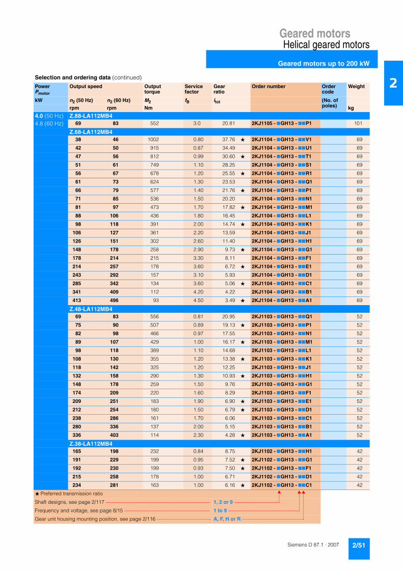
Geared motorsHelical geared motors
Geared motors up to 200 kW
2/51Siemens D 87.1 · 2007
2
4.0 (50 Hz) Z.88-LA112MB44.8 (60 Hz) 69 83 552 3.0 20.81 2KJ1105 - 7GH13 - 77P1 101
Z.68-LA112MB438 46 1002 0.80 37.76 � 2KJ1104 - 7GH13 - 77V1 69
42 50 915 0.87 34.49 2KJ1104 - 7GH13 - 77U1 69
47 56 812 0.99 30.60 � 2KJ1104 - 7GH13 - 77T1 69
51 61 749 1.10 28.25 2KJ1104 - 7GH13 - 77S1 69
56 67 678 1.20 25.55 � 2KJ1104 - 7GH13 - 77R1 69
61 73 624 1.30 23.53 2KJ1104 - 7GH13 - 77Q1 69
66 79 577 1.40 21.76 � 2KJ1104 - 7GH13 - 77P1 69
71 85 536 1.50 20.20 2KJ1104 - 7GH13 - 77N1 69
81 97 473 1.70 17.82 � 2KJ1104 - 7GH13 - 77M1 69
88 106 436 1.80 16.45 2KJ1104 - 7GH13 - 77L1 69
98 118 391 2.00 14.74 � 2KJ1104 - 7GH13 - 77K1 69
106 127 361 2.20 13.59 2KJ1104 - 7GH13 - 77J1 69
126 151 302 2.60 11.40 2KJ1104 - 7GH13 - 77H1 69
148 178 258 2.90 9.73 � 2KJ1104 - 7GH13 - 77G1 69
178 214 215 3.30 8.11 2KJ1104 - 7GH13 - 77F1 69
214 257 178 3.60 6.72 � 2KJ1104 - 7GH13 - 77E1 69
243 292 157 3.10 5.93 2KJ1104 - 7GH13 - 77D1 69
285 342 134 3.60 5.06 � 2KJ1104 - 7GH13 - 77C1 69
341 409 112 4.20 4.22 2KJ1104 - 7GH13 - 77B1 69
413 496 93 4.50 3.49 � 2KJ1104 - 7GH13 - 77A1 69
Z.48-LA112MB469 83 556 0.81 20.95 2KJ1103 - 7GH13 - 77Q1 52
75 90 507 0.89 19.13 � 2KJ1103 - 7GH13 - 77P1 52
82 98 466 0.97 17.55 2KJ1103 - 7GH13 - 77N1 52
89 107 429 1.00 16.17 � 2KJ1103 - 7GH13 - 77M1 52
98 118 389 1.10 14.68 2KJ1103 - 7GH13 - 77L1 52
108 130 355 1.20 13.38 � 2KJ1103 - 7GH13 - 77K1 52
118 142 325 1.20 12.25 2KJ1103 - 7GH13 - 77J1 52
132 158 290 1.30 10.93 � 2KJ1103 - 7GH13 - 77H1 52
148 178 259 1.50 9.76 2KJ1103 - 7GH13 - 77G1 52
174 209 220 1.60 8.29 2KJ1103 - 7GH13 - 77F1 52
209 251 183 1.90 6.90 � 2KJ1103 - 7GH13 - 77E1 52
212 254 180 1.50 6.79 � 2KJ1103 - 7GH13 - 77D1 52
238 286 161 1.70 6.06 2KJ1103 - 7GH13 - 77C1 52
280 336 137 2.00 5.15 2KJ1103 - 7GH13 - 77B1 52
336 403 114 2.30 4.28 � 2KJ1103 - 7GH13 - 77A1 52
Z.38-LA112MB4165 198 232 0.84 8.75 2KJ1102 - 7GH13 - 77H1 42
191 229 199 0.95 7.52 � 2KJ1102 - 7GH13 - 77G1 42
192 230 199 0.93 7.50 � 2KJ1102 - 7GH13 - 77F1 42
215 258 178 1.00 6.71 2KJ1102 - 7GH13 - 77D1 42
234 281 163 1.00 6.16 � 2KJ1102 - 7GH13 - 77C1 42
Selection and ordering data (continued)
PowerPmotor
Output speed Output torque
Service factor
Gear ratio
Order number Order code
Weight
kW n2 (50 Hz) n2 (60 Hz) M2 fB itot (No. of poles)rpm rpm Nm kg
� Preferred transmission ratio
Shaft designs, see page 2/117 –––––––––––––––––––––––––––––––––––––––––– 1, 2 or 9 –––––––––––––––––––
Frequency and voltage, see page 8/15 ––––––––––––––––––––––––––––––––––– 1 to 9 ––––––––––––––––––––––––––––––
Gear unit housing mounting position, see page 2/116 –––––––––––––––––––––– A, F, H or R ––––––––––––––––––––––––––

Geared motorsHelical geared motors
Geared motors up to 200 kW
2/52 Siemens D 87.1 · 2007
2
4.0 (50 Hz) Z.38-LA112MB44.8 (60 Hz) 259 311 147 1.1 5.55 2KJ1102 - 7GH13 - 77B1 42
302 362 127 1.3 4.77 � 2KJ1102 - 7GH13 - 77A1 42
E.128-LA112MB4142 170 269 2.0 10.14 � 2KJ1006 - 7GH13 - 77T1 126
153 184 249 2.3 9.40 2KJ1006 - 7GH13 - 77S1 126
161 193 237 2.7 8.94 � 2KJ1006 - 7GH13 - 77R1 126
172 206 222 3.2 8.35 2KJ1006 - 7GH13 - 77Q1 126
195 234 196 4.2 7.37 � 2KJ1006 - 7GH13 - 77P1 126
E.108-LA112MB4264 317 145 4.6 5.46 � 2KJ1005 - 7GH13 - 77K1 89
E.88-LA112MB4139 167 274 0.84 10.33 � 2KJ1004 - 7GH13 - 77S1 68
152 182 251 0.84 9.46 2KJ1004 - 7GH13 - 77R1 68
171 205 223 1.10 8.42 � 2KJ1004 - 7GH13 - 77Q1 68
187 224 204 1.20 7.69 2KJ1004 - 7GH13 - 77P1 68
204 245 188 1.50 7.07 � 2KJ1004 - 7GH13 - 77N1 68
221 265 173 1.70 6.53 2KJ1004 - 7GH13 - 77M1 68
238 286 161 1.70 6.06 � 2KJ1004 - 7GH13 - 77L1 68
255 306 150 2.10 5.65 2KJ1004 - 7GH13 - 77K1 68
282 338 136 2.70 5.11 � 2KJ1004 - 7GH13 - 77J1 68
306 367 125 3.10 4.70 2KJ1004 - 7GH13 - 77H1 68
340 408 112 3.60 4.23 � 2KJ1004 - 7GH13 - 77G1 68
369 443 103 3.70 3.90 2KJ1004 - 7GH13 - 77F1 68
436 523 88 5.10 3.30 2KJ1004 - 7GH13 - 77E1 68
500 600 76 5.70 2.88 � 2KJ1004 - 7GH13 - 77D1 68
E.68-LA112MB4182 218 210 0.81 7.92 � 2KJ1003 - 7GH13 - 77S1 51
224 269 170 1.00 6.42 � 2KJ1003 - 7GH13 - 77P1 51
243 292 157 1.20 5.92 2KJ1003 - 7GH13 - 77N1 51
269 323 142 1.50 5.36 � 2KJ1003 - 7GH13 - 77M1 51
292 350 131 1.70 4.93 2KJ1003 - 7GH13 - 77L1 51
316 379 121 1.80 4.56 � 2KJ1003 - 7GH13 - 77K1 51
340 408 112 2.00 4.24 2KJ1003 - 7GH13 - 77J1 51
385 462 99 2.30 3.74 � 2KJ1003 - 7GH13 - 77H1 51
417 500 92 2.60 3.45 2KJ1003 - 7GH13 - 77G1 51
466 559 82 3.00 3.09 � 2KJ1003 - 7GH13 - 77F1 51
505 606 76 3.30 2.85 2KJ1003 - 7GH13 - 77E1 51
603 724 63 3.60 2.39 2KJ1003 - 7GH13 - 77D1 51
706 847 54 3.90 2.04 � 2KJ1003 - 7GH13 - 77C1 51
847 1016 45 3.90 1.70 2KJ1003 - 7GH13 - 77B1 51
1021 1225 37 4.00 1.41 � 2KJ1003 - 7GH13 - 77A1 51
E.48-LA112MB4283 340 135 0.89 5.08 � 2KJ1002 - 7GH13 - 77M1 41
312 374 123 1.10 4.62 2KJ1002 - 7GH13 - 77L1 41
342 410 112 1.30 4.21 � 2KJ1002 - 7GH13 - 77K1 41
Selection and ordering data (continued)
PowerPmotor
Output speed Output torque
Service factor
Gear ratio
Order number Order code
Weight
kW n2 (50 Hz) n2 (60 Hz) M2 fB itot (No. of poles)rpm rpm Nm kg
� Preferred transmission ratio
Shaft designs, see page 2/117 –––––––––––––––––––––––––––––––––––––––––– 1, 2 or 9 –––––––––––––––––––
Frequency and voltage, see page 8/15 ––––––––––––––––––––––––––––––––––– 1 to 9 ––––––––––––––––––––––––––––––
Gear unit housing mounting position, see page 2/116 –––––––––––––––––––––– A, F, H or R ––––––––––––––––––––––––––
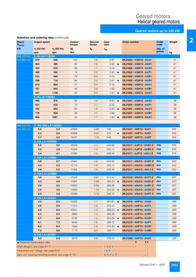
Geared motorsHelical geared motors
Geared motors up to 200 kW
2/53Siemens D 87.1 · 2007
2
4.0 (50 Hz) E.48-LA112MB44.8 (60 Hz) 372 446 103 1.6 3.87 2KJ1002 - 7GH13 - 77J1 41
404 485 94 1.5 3.56 � 2KJ1002 - 7GH13 - 77H1 41
444 533 86 1.7 3.24 2KJ1002 - 7GH13 - 77G1 41
488 586 78 2.2 2.95 � 2KJ1002 - 7GH13 - 77F1 41
533 640 72 2.2 2.70 2KJ1002 - 7GH13 - 77E1 41
598 718 64 2.3 2.41 � 2KJ1002 - 7GH13 - 77D1 41
670 804 57 2.4 2.15 2KJ1002 - 7GH13 - 77C1 41
787 944 48 2.4 1.83 2KJ1002 - 7GH13 - 77B1 41
947 1136 40 2.5 1.52 � 2KJ1002 - 7GH13 - 77A1 41
E.38-LA112MB4480 576 80 1.0 3.00 � 2KJ1001 - 7GH13 - 77G1 38
527 632 72 1.1 2.73 2KJ1001 - 7GH13 - 77F1 38
702 842 54 1.5 2.05 � 2KJ1001 - 7GH13 - 77C1 38
778 934 49 1.7 1.85 2KJ1001 - 7GH13 - 77B1 38
906 1087 42 1.7 1.59 � 2KJ1001 - 7GH13 - 77A1 38
5.5 (50 Hz) D.188-Z68-LA132SB46.6 (60 Hz) 2.0 2.4 24909 0.80 746 2KJ1237 - 7HF13 - 77F1 655
2.4 2.9 20668 0.97 619 � 2KJ1237 - 7HF13 - 77E1 655
2.7 3.2 18231 1.10 546 2KJ1237 - 7HF13 - 77D1 655
D.188-LA160MB82.9 3.5 18038 1.1 243.82 2KJ1211 - 7JF13 - 77N1-Z P02 676
3.2 3.8 16288 1.2 220.17 2KJ1211 - 7JF13 - 77M1-Z P02 676
3.4 4.1 15265 1.3 206.34 2KJ1211 - 7JF13 - 77L1-Z P02 676
D.188-LA132MB63.9 4.7 13481 1.5 243.82 2KJ1211 - 7HJ13 - 77N1-Z P01 652
4.3 5.2 12173 1.6 220.17 2KJ1211 - 7HJ13 - 77M1-Z P01 652
4.6 5.5 11408 1.8 206.34 2KJ1211 - 7HJ13 - 77L1-Z P01 652
D.168-LA132MB63.0 3.6 17328 0.81 313.41 2KJ1210 - 7HJ13 - 77T1-Z P01 507
3.3 4.0 15991 0.88 289.23 � 2KJ1210 - 7HJ13 - 77S1-Z P01 507
3.5 4.2 14834 0.94 268.29 2KJ1210 - 7HJ13 - 77R1-Z P01 507
3.8 4.6 13993 1.00 253.08 � 2KJ1210 - 7HJ13 - 77Q1-Z P01 507
4.0 4.8 13088 1.10 236.72 2KJ1210 - 7HJ13 - 77P1-Z P01 507
D.168-LA132SB44.3 5.2 12332 1.1 341.61 � 2KJ1210 - 7HF13 - 77U1 499
4.6 5.5 11314 1.2 313.41 2KJ1210 - 7HF13 - 77T1 499
5.0 6.0 10441 1.3 289.23 � 2KJ1210 - 7HF13 - 77S1 499
5.4 6.5 9685 1.4 268.29 2KJ1210 - 7HF13 - 77R1 499
5.7 6.8 9136 1.5 253.08 � 2KJ1210 - 7HF13 - 77Q1 499
6.1 7.3 8546 1.6 236.72 2KJ1210 - 7HF13 - 77P1 499
6.9 8.3 7599 1.8 210.49 � 2KJ1210 - 7HF13 - 77N1 499
7.3 8.8 7173 2.0 198.71 2KJ1210 - 7HF13 - 77M1 499
D.148-LA132SB45.3 6.4 9972 0.8 276.23 2KJ1208 - 7HF13 - 77U1 328
Selection and ordering data (continued)
PowerPmotor
Output speed Output torque
Service factor
Gear ratio
Order number Order code
Weight
kW n2 (50 Hz) n2 (60 Hz) M2 fB itot (No. of poles)rpm rpm Nm kg
� Preferred transmission ratio
Shaft designs, see page 2/117 –––––––––––––––––––––––––––––––––––––––––– 1, 2 or 9 –––––––––––––––––––
Frequency and voltage, see page 8/15 ––––––––––––––––––––––––––––––––––– 1 to 9 ––––––––––––––––––––––––––––––
Gear unit housing mounting position, see page 2/116 –––––––––––––––––––––– A, F, H or R ––––––––––––––––––––––––––

Geared motorsHelical geared motors
Geared motors up to 200 kW
2/54 Siemens D 87.1 · 2007
2
5.5 (50 Hz) D.148-LA132SB46.6 (60 Hz) 5.7 6.8 9195 0.87 254.70 � 2KJ1208 - 7HF13 - 77T1 328
6.2 7.4 8521 0.94 236.05 2KJ1208 - 7HF13 - 77S1 328
6.5 7.8 8102 0.99 224.43 � 2KJ1208 - 7HF13 - 77R1 328
6.9 8.3 7572 1.10 209.76 2KJ1208 - 7HF13 - 77Q1 328
7.9 9.5 6680 1.20 185.03 � 2KJ1208 - 7HF13 - 77P1 328
8.3 10.0 6300 1.30 174.53 2KJ1208 - 7HF13 - 77N1 328
9.3 11.2 5645 1.40 156.38 � 2KJ1208 - 7HF13 - 77M1 328
10.1 12.1 5212 1.50 144.39 2KJ1208 - 7HF13 - 77L1 328
11.8 14.2 4454 1.80 123.37 2KJ1208 - 7HF13 - 77K1 328
13.0 15.6 4025 2.00 111.50 � 2KJ1208 - 7HF13 - 77J1 328
13.5 16.2 3878 2.10 107.42 2KJ1208 - 7HF13 - 77H1 328
Z.148-LA132SB425.0 30.0 2076 2.2 57.50 2KJ1108 - 7HF13 - 77B2 316
D.128-LA132SB48.5 10.2 6195 0.82 171.62 2KJ1207 - 7HF13 - 77P1 238
9.1 10.9 5762 0.89 159.60 � 2KJ1207 - 7HF13 - 77N1 238
9.8 11.8 5378 0.95 148.99 2KJ1207 - 7HF13 - 77M1 238
10.9 13.1 4812 1.10 133.30 � 2KJ1207 - 7HF13 - 77L1 238
11.8 14.2 4459 1.10 123.53 2KJ1207 - 7HF13 - 77K1 238
12.8 15.4 4088 1.20 113.24 � 2KJ1207 - 7HF13 - 77J1 238
14.0 16.8 3747 1.40 103.80 2KJ1207 - 7HF13 - 77H1 238
16.4 19.7 3193 1.60 88.46 2KJ1207 - 7HF13 - 77G1 238
18.6 22.0 2818 1.80 78.06 � 2KJ1207 - 7HF13 - 77F1 238
22.0 26.0 2398 2.10 66.43 2KJ1207 - 7HF13 - 77E1 238
Z.128-LA132SB433 40 1595 2.1 44.19 � 2KJ1107 - 7HF13 - 77D2 229
36 43 1479 2.2 40.96 2KJ1107 - 7HF13 - 77C2 229
D.108-LA132SB413.8 16.6 3793 0.82 105.08 � 2KJ1206 - 7HF13 - 77G1 161
15.0 18.0 3500 0.89 96.94 2KJ1206 - 7HF13 - 77F1 161
17.7 21.0 2965 1.00 82.14 2KJ1206 - 7HF13 - 77E1 161
20.0 24.0 2584 1.20 71.59 � 2KJ1206 - 7HF13 - 77D1 161
24.0 29.0 2198 1.40 60.90 2KJ1206 - 7HF13 - 77C1 161
Z.108-LA132SB430 36 1747 1.8 48.38 � 2KJ1106 - 7HF13 - 77C2 157
33 40 1600 1.9 44.31 2KJ1106 - 7HF13 - 77B2 157
36 43 1474 2.1 40.82 � 2KJ1106 - 7HF13 - 77A2 157
38 46 1364 2.3 37.79 2KJ1106 - 7HF13 - 77X1 157
41 49 1269 2.4 35.14 � 2KJ1106 - 7HF13 - 77W1 157
44 53 1184 2.6 32.81 2KJ1106 - 7HF13 - 77V1 157
D.88-LA132SB425 30 2091 0.80 57.93 2KJ1205 - 7HF13 - 77D1 113
29 35 1784 0.94 49.42 � 2KJ1205 - 7HF13 - 77C1 113
35 42 1487 1.10 41.19 2KJ1205 - 7HF13 - 77B1 113
Selection and ordering data (continued)
PowerPmotor
Output speed Output torque
Service factor
Gear ratio
Order number Order code
Weight
kW n2 (50 Hz) n2 (60 Hz) M2 fB itot (No. of poles)rpm rpm Nm kg
� Preferred transmission ratio
Shaft designs, see page 2/117 –––––––––––––––––––––––––––––––––––––––––– 1, 2 or 9 –––––––––––––––––––
Frequency and voltage, see page 8/15 ––––––––––––––––––––––––––––––––––– 1 to 9 ––––––––––––––––––––––––––––––
Gear unit housing mounting position, see page 2/116 –––––––––––––––––––––– A, F, H or R ––––––––––––––––––––––––––

Geared motorsHelical geared motors
Geared motors up to 200 kW
2/55Siemens D 87.1 · 2007
2
5.5 (50 Hz) Z.88-LA132SB46.6 (60 Hz) 39 47 1345 1.2 37.27 � 2KJ1105 - 7HF13 - 77W1 111
43 52 1230 1.4 34.07 2KJ1105 - 7HF13 - 77V1 111
46 55 1131 1.5 31.32 � 2KJ1105 - 7HF13 - 77U1 111
50 60 1044 1.6 28.93 2KJ1105 - 7HF13 - 77T1 111
54 65 969 1.7 26.85 � 2KJ1105 - 7HF13 - 77S1 111
58 70 903 1.9 25.01 2KJ1105 - 7HF13 - 77R1 111
64 77 816 2.1 22.61 � 2KJ1105 - 7HF13 - 77Q1 111
70 84 751 2.2 20.81 2KJ1105 - 7HF13 - 77P1 111
78 94 676 2.5 18.72 � 2KJ1105 - 7HF13 - 77N1 111
84 101 623 2.7 17.27 2KJ1105 - 7HF13 - 77M1 111
100 120 528 3.1 14.63 2KJ1105 - 7HF13 - 77L1 111
114 137 460 3.4 12.75 � 2KJ1105 - 7HF13 - 77K1 111
134 161 392 3.8 10.85 2KJ1105 - 7HF13 - 77J1 111
327 392 161 5.0 4.45 � 2KJ1105 - 7HF13 - 77C1 111
384 461 137 5.4 3.79 � 2KJ1105 - 7HF13 - 77B1 111
Z.68-LA132SB457 68 922 0.87 25.55 � 2KJ1104 - 7HF13 - 77R1 79
62 74 849 0.94 23.53 2KJ1104 - 7HF13 - 77Q1 79
67 80 786 1.00 21.76 � 2KJ1104 - 7HF13 - 77P1 79
72 86 729 1.10 20.20 2KJ1104 - 7HF13 - 77N1 79
82 98 643 1.20 17.82 � 2KJ1104 - 7HF13 - 77M1 79
88 106 594 1.30 16.45 2KJ1104 - 7HF13 - 77L1 79
99 119 532 1.50 14.74 � 2KJ1104 - 7HF13 - 77K1 79
107 128 491 1.60 13.59 2KJ1104 - 7HF13 - 77J1 79
128 154 412 1.90 11.40 2KJ1104 - 7HF13 - 77H1 79
150 180 351 2.10 9.73 � 2KJ1104 - 7HF13 - 77G1 79
179 215 293 2.40 8.11 2KJ1104 - 7HF13 - 77F1 79
217 260 243 2.70 6.72 � 2KJ1104 - 7HF13 - 77E1 79
245 294 214 2.30 5.93 2KJ1104 - 7HF13 - 77D1 79
288 346 183 2.60 5.06 � 2KJ1104 - 7HF13 - 77C1 79
345 414 152 3.10 4.22 2KJ1104 - 7HF13 - 77B1 79
417 500 126 3.30 3.49 � 2KJ1104 - 7HF13 - 77A1 79
Z.48-LA132SB4109 131 483 0.85 13.38 � 2KJ1103 - 7HF13 - 77K1 62
119 143 442 0.90 12.25 2KJ1103 - 7HF13 - 77J1 62
133 160 395 0.99 10.93 � 2KJ1103 - 7HF13 - 77H1 62
149 179 352 1.10 9.76 2KJ1103 - 7HF13 - 77G1 62
176 211 299 1.20 8.29 2KJ1103 - 7HF13 - 77F1 62
211 253 249 1.40 6.90 � 2KJ1103 - 7HF13 - 77E1 62
214 257 245 1.10 6.79 � 2KJ1103 - 7HF13 - 77D1 62
240 288 219 1.20 6.06 2KJ1103 - 7HF13 - 77C1 62
283 340 186 1.50 5.15 2KJ1103 - 7HF13 - 77B1 62
340 408 155 1.70 4.28 � 2KJ1103 - 7HF13 - 77A1 62
E.148-LA132SB4106 127 493 1.2 13.67 � 2KJ1007 - 7HF13 - 77U1 160
Selection and ordering data (continued)
PowerPmotor
Output speed Output torque
Service factor
Gear ratio
Order number Order code
Weight
kW n2 (50 Hz) n2 (60 Hz) M2 fB itot (No. of poles)rpm rpm Nm kg
� Preferred transmission ratio
Shaft designs, see page 2/117 –––––––––––––––––––––––––––––––––––––––––– 1, 2 or 9 –––––––––––––––––––
Frequency and voltage, see page 8/15 ––––––––––––––––––––––––––––––––––– 1 to 9 ––––––––––––––––––––––––––––––
Gear unit housing mounting position, see page 2/116 –––––––––––––––––––––– A, F, H or R ––––––––––––––––––––––––––

Geared motorsHelical geared motors
Geared motors up to 200 kW
2/56 Siemens D 87.1 · 2007
2
5.5 (50 Hz) E.148-LA132SB46.6 (60 Hz) 116 139 453 1.3 12.54 2KJ1007 - 7HF13 - 77T1 160
126 151 418 1.6 11.57 � 2KJ1007 - 7HF13 - 77S1 160
136 163 387 2.0 10.73 2KJ1007 - 7HF13 - 77R1 160
144 173 366 2.2 10.13 � 2KJ1007 - 7HF13 - 77Q1 160
154 185 342 2.7 9.47 2KJ1007 - 7HF13 - 77P1 160
173 208 304 3.3 8.42 � 2KJ1007 - 7HF13 - 77N1 160
183 220 287 3.7 7.95 2KJ1007 - 7HF13 - 77M1 160
204 245 258 4.3 7.14 � 2KJ1007 - 7HF13 - 77L1 160
E.128-LA132SB4143 172 366 1.5 10.14 � 2KJ1006 - 7HF13 - 77T1 136
155 186 339 1.7 9.40 2KJ1006 - 7HF13 - 77S1 136
163 196 323 2.0 8.94 � 2KJ1006 - 7HF13 - 77R1 136
174 209 301 2.4 8.35 2KJ1006 - 7HF13 - 77Q1 136
197 236 266 3.1 7.37 � 2KJ1006 - 7HF13 - 77P1 136
209 251 251 3.5 6.95 2KJ1006 - 7HF13 - 77N1 136
234 281 225 4.1 6.23 � 2KJ1006 - 7HF13 - 77M1 136
253 304 208 4.6 5.75 2KJ1006 - 7HF13 - 77L1 136
E.108-LA132SB4266 319 197 3.3 5.46 � 2KJ1005 - 7HF13 - 77K1 99
291 349 180 3.8 5.00 2KJ1005 - 7HF13 - 77J1 99
342 410 154 4.7 4.26 2KJ1005 - 7HF13 - 77H1 99
387 464 136 4.4 3.76 � 2KJ1005 - 7HF13 - 77G1 99
E.88-LA132SB4173 208 304 0.81 8.42 � 2KJ1004 - 7HF13 - 77Q1 78
189 227 278 0.88 7.69 2KJ1004 - 7HF13 - 77P1 78
206 247 255 1.10 7.07 � 2KJ1004 - 7HF13 - 77N1 78
223 268 236 1.30 6.53 2KJ1004 - 7HF13 - 77M1 78
240 288 219 1.30 6.06 � 2KJ1004 - 7HF13 - 77L1 78
258 310 204 1.60 5.65 2KJ1004 - 7HF13 - 77K1 78
285 342 184 2.00 5.11 � 2KJ1004 - 7HF13 - 77J1 78
310 372 170 2.30 4.70 2KJ1004 - 7HF13 - 77H1 78
344 413 153 2.60 4.23 � 2KJ1004 - 7HF13 - 77G1 78
373 448 141 2.70 3.90 2KJ1004 - 7HF13 - 77F1 78
441 529 119 3.80 3.30 2KJ1004 - 7HF13 - 77E1 78
505 606 104 4.20 2.88 � 2KJ1004 - 7HF13 - 77D1 78
594 713 88 4.70 2.45 2KJ1004 - 7HF13 - 77C1 78
696 835 75 5.60 2.09 � 2KJ1004 - 7HF13 - 77B1 78
851 1021 62 5.80 1.71 � 2KJ1004 - 7HF13 - 77A1 78
E.68-LA132SB4246 295 214 0.89 5.92 2KJ1003 - 7HF13 - 77N1 61
271 325 193 1.10 5.36 � 2KJ1003 - 7HF13 - 77M1 61
295 354 178 1.30 4.93 2KJ1003 - 7HF13 - 77L1 61
319 383 165 1.30 4.56 � 2KJ1003 - 7HF13 - 77K1 61
343 412 153 1.50 4.24 2KJ1003 - 7HF13 - 77J1 61
Selection and ordering data (continued)
PowerPmotor
Output speed Output torque
Service factor
Gear ratio
Order number Order code
Weight
kW n2 (50 Hz) n2 (60 Hz) M2 fB itot (No. of poles)rpm rpm Nm kg
� Preferred transmission ratio
Shaft designs, see page 2/117 –––––––––––––––––––––––––––––––––––––––––– 1, 2 or 9 –––––––––––––––––––
Frequency and voltage, see page 8/15 ––––––––––––––––––––––––––––––––––– 1 to 9 ––––––––––––––––––––––––––––––
Gear unit housing mounting position, see page 2/116 –––––––––––––––––––––– A, F, H or R ––––––––––––––––––––––––––

Geared motorsHelical geared motors
Geared motors up to 200 kW
2/57Siemens D 87.1 · 2007
2
5.5 (50 Hz) E.68-LA132SB46.6 (60 Hz) 389 467 135 1.7 3.74 � 2KJ1003 - 7HF13 - 77H1 61
422 506 125 1.9 3.45 2KJ1003 - 7HF13 - 77G1 61
471 565 112 2.2 3.09 � 2KJ1003 - 7HF13 - 77F1 61
511 613 103 2.4 2.85 2KJ1003 - 7HF13 - 77E1 61
609 731 86 2.7 2.39 2KJ1003 - 7HF13 - 77D1 61
713 856 74 2.9 2.04 � 2KJ1003 - 7HF13 - 77C1 61
856 1027 61 2.9 1.70 2KJ1003 - 7HF13 - 77B1 61
1032 1238 51 2.9 1.41 � 2KJ1003 - 7HF13 - 77A1 61
E.48-LA132SB4346 415 152 0.99 4.21 � 2KJ1002 - 7HF13 - 77K1 51
376 451 140 1.10 3.87 2KJ1002 - 7HF13 - 77J1 51
409 491 129 1.10 3.56 � 2KJ1002 - 7HF13 - 77H1 51
449 539 117 1.30 3.24 2KJ1002 - 7HF13 - 77G1 51
493 592 106 1.60 2.95 � 2KJ1002 - 7HF13 - 77F1 51
539 647 98 1.60 2.70 2KJ1002 - 7HF13 - 77E1 51
604 725 87 1.70 2.41 � 2KJ1002 - 7HF13 - 77D1 51
677 812 78 1.70 2.15 2KJ1002 - 7HF13 - 77C1 51
795 954 66 1.70 1.83 2KJ1002 - 7HF13 - 77B1 51
957 1148 55 1.80 1.52 � 2KJ1002 - 7HF13 - 77A1 51
7.5 (50 Hz) D.188-Z68-LA132M49.0 (60 Hz) 2.7 3.2 24896 0.8 546.00 2KJ1237 - 7HH13 - 77D1 663
D.188-LA160MB63.9 4.7 18191 1.1 243.82 2KJ1211 - 7JF13 - 77N1-Z P01 676
4.4 5.3 16427 1.2 220.17 2KJ1211 - 7JF13 - 77M1-Z P01 676
4.7 5.6 15395 1.3 206.34 2KJ1211 - 7JF13 - 77L1-Z P01 676
5.4 6.5 13223 1.5 177.23 � 2KJ1211 - 7JF13 - 77K1-Z P01 676
D.188-LA132M46.0 7.2 12002 1.7 243.82 2KJ1211 - 7HH13 - 77N1 652
6.6 7.9 10838 1.8 220.17 2KJ1211 - 7HH13 - 77M1 652
7.1 8.5 10157 2.0 206.34 2KJ1211 - 7HH13 - 77L1 652
D.168-LA132M44.3 5.2 16816 0.83 341.61 � 2KJ1210 - 7HH13 - 77U1 507
4.6 5.5 15428 0.91 313.41 2KJ1210 - 7HH13 - 77T1 507
5.0 6.0 14238 0.98 289.23 � 2KJ1210 - 7HH13 - 77S1 507
5.4 6.5 13207 1.10 268.29 2KJ1210 - 7HH13 - 77R1 507
5.7 6.8 12458 1.10 253.08 � 2KJ1210 - 7HH13 - 77Q1 507
6.1 7.3 11653 1.20 236.72 2KJ1210 - 7HH13 - 77P1 507
6.9 8.3 10362 1.40 210.49 � 2KJ1210 - 7HH13 - 77N1 507
7.3 8.8 9782 1.40 198.71 2KJ1210 - 7HH13 - 77M1 507
8.2 9.8 8781 1.60 178.38 � 2KJ1210 - 7HH13 - 77L1 507
8.9 10.7 8059 1.70 163.72 2KJ1210 - 7HH13 - 77K1 507
10.3 12.4 6955 2.00 141.28 2KJ1210 - 7HH13 - 77J1 507
D.148-LA132M47.9 9.5 9108 0.88 185.03 � 2KJ1208 - 7HH13 - 77P1 336
Selection and ordering data (continued)
PowerPmotor
Output speed Output torque
Service factor
Gear ratio
Order number Order code
Weight
kW n2 (50 Hz) n2 (60 Hz) M2 fB itot (No. of poles)rpm rpm Nm kg
� Preferred transmission ratio
Shaft designs, see page 2/117 –––––––––––––––––––––––––––––––––––––––––– 1, 2 or 9 –––––––––––––––––––
Frequency and voltage, see page 8/15 ––––––––––––––––––––––––––––––––––– 1 to 9 ––––––––––––––––––––––––––––––
Gear unit housing mounting position, see page 2/116 –––––––––––––––––––––– A, F, H or R ––––––––––––––––––––––––––

Geared motorsHelical geared motors
Geared motors up to 200 kW
2/58 Siemens D 87.1 · 2007
2
7.5 (50 Hz) D.148-LA132M49.0 (60 Hz) 8.3 10.0 8592 0.93 174.53 2KJ1208 - 7HH13 - 77N1 336
9.3 11.2 7698 1.00 156.38 � 2KJ1208 - 7HH13 - 77M1 336
10.1 12.1 7108 1.10 144.39 2KJ1208 - 7HH13 - 77L1 336
11.8 14.2 6073 1.30 123.37 2KJ1208 - 7HH13 - 77K1 336
13.0 15.6 5489 1.50 111.50 � 2KJ1208 - 7HH13 - 77J1 336
13.5 16.2 5288 1.50 107.42 2KJ1208 - 7HH13 - 77H1 336
15.7 18.8 4574 1.70 92.91 2KJ1208 - 7HH13 - 77G1 336
18.0 22.0 3989 2.00 81.04 � 2KJ1208 - 7HH13 - 77F1 336
21.0 25.0 3414 2.30 69.36 � 2KJ1208 - 7HH13 - 77E1 336
Z.148-LA132M425.0 30.0 2831 1.6 57.50 2KJ1108 - 7HH13 - 77B2 324
D.128-LA132M411.8 14.2 6081 0.84 123.53 2KJ1207 - 7HH13 - 77K1 246
12.8 15.4 5574 0.91 113.24 � 2KJ1207 - 7HH13 - 77J1 246
14.0 16.8 5110 1.00 103.80 2KJ1207 - 7HH13 - 77H1 246
16.4 19.7 4355 1.20 88.46 2KJ1207 - 7HH13 - 77G1 246
18.6 22.0 3843 1.30 78.06 � 2KJ1207 - 7HH13 - 77F1 246
22.0 26.0 3270 1.60 66.43 2KJ1207 - 7HH13 - 77E1 246
25.0 30.0 2833 1.80 57.56 � 2KJ1207 - 7HH13 - 77D1 246
30.0 36.0 2385 2.10 48.44 � 2KJ1207 - 7HH13 - 77C1 246
33.0 40.0 2152 2.40 43.71 2KJ1207 - 7HH13 - 77B1 246
Z.128-LA132M433 40 2175 1.5 44.19 � 2KJ1107 - 7HH13 - 77D2 237
36 43 2016 1.6 40.96 2KJ1107 - 7HH13 - 77C2 237
D.108-LA132M420 24 3524 0.88 71.59 � 2KJ1206 - 7HH13 - 77D1 169
24 29 2998 1.00 60.90 2KJ1206 - 7HH13 - 77C1 169
Z.108-LA132M430 36 2382 1.3 48.38 � 2KJ1106 - 7HH13 - 77C2 165
33 40 2181 1.4 44.31 2KJ1106 - 7HH13 - 77B2 165
36 43 2009 1.5 40.82 � 2KJ1106 - 7HH13 - 77A2 165
38 46 1860 1.7 37.79 2KJ1106 - 7HH13 - 77X1 165
41 49 1730 1.8 35.14 � 2KJ1106 - 7HH13 - 77W1 165
44 53 1615 1.9 32.81 2KJ1106 - 7HH13 - 77V1 165
50 60 1445 2.1 29.35 � 2KJ1106 - 7HH13 - 77U1 165
54 65 1339 2.3 27.20 2KJ1106 - 7HH13 - 77T1 165
58 70 1228 2.5 24.94 � 2KJ1106 - 7HH13 - 77S1 165
64 77 1125 2.8 22.86 2KJ1106 - 7HH13 - 77R1 165
75 90 959 3.2 19.48 2KJ1106 - 7HH13 - 77Q1 165
278 334 258 4.4 5.24 � 2KJ1106 - 7HH13 - 77D1 165
D.88-LA132M435 42 2028 0.83 41.19 2KJ1205 - 7HH13 - 77B1 121
Selection and ordering data (continued)
PowerPmotor
Output speed Output torque
Service factor
Gear ratio
Order number Order code
Weight
kW n2 (50 Hz) n2 (60 Hz) M2 fB itot (No. of poles)rpm rpm Nm kg
� Preferred transmission ratio
Shaft designs, see page 2/117 –––––––––––––––––––––––––––––––––––––––––– 1, 2 or 9 –––––––––––––––––––
Frequency and voltage, see page 8/15 ––––––––––––––––––––––––––––––––––– 1 to 9 ––––––––––––––––––––––––––––––
Gear unit housing mounting position, see page 2/116 –––––––––––––––––––––– A, F, H or R ––––––––––––––––––––––––––

Geared motorsHelical geared motors
Geared motors up to 200 kW
2/59Siemens D 87.1 · 2007
2
7.5 (50 Hz) Z.88-LA132M49.0 (60 Hz) 39 47 1835 0.92 37.27 � 2KJ1105 - 7HH13 - 77W1 119
43 52 1677 1.00 34.07 2KJ1105 - 7HH13 - 77V1 119
46 55 1542 1.10 31.32 � 2KJ1105 - 7HH13 - 77U1 119
50 60 1424 1.20 28.93 2KJ1105 - 7HH13 - 77T1 119
54 65 1322 1.30 26.85 � 2KJ1105 - 7HH13 - 77S1 119
58 70 1231 1.40 25.01 2KJ1105 - 7HH13 - 77R1 119
64 77 1113 1.50 22.61 � 2KJ1105 - 7HH13 - 77Q1 119
70 84 1024 1.60 20.81 2KJ1105 - 7HH13 - 77P1 119
78 94 922 1.80 18.72 � 2KJ1105 - 7HH13 - 77N1 119
84 101 850 2.00 17.27 2KJ1105 - 7HH13 - 77M1 119
100 120 720 2.20 14.63 2KJ1105 - 7HH13 - 77L1 119
114 137 628 2.50 12.75 � 2KJ1105 - 7HH13 - 77K1 119
134 161 534 2.80 10.85 2KJ1105 - 7HH13 - 77J1 119
157 188 456 3.00 9.26 � 2KJ1105 - 7HH13 - 77H1 119
192 230 374 3.50 7.59 � 2KJ1105 - 7HH13 - 77G1 119
209 251 343 3.70 6.96 2KJ1105 - 7HH13 - 77F1 119
245 294 292 4.10 5.94 � 2KJ1105 - 7HH13 - 77E1 119
299 359 240 4.60 4.87 � 2KJ1105 - 7HH13 - 77D1 119
327 392 219 3.70 4.45 � 2KJ1105 - 7HH13 - 77C1 119
384 461 187 4.00 3.79 � 2KJ1105 - 7HH13 - 77B1 119
468 562 153 4.30 3.11 � 2KJ1105 - 7HH13 - 77A1 119
Z.68-LA132M472 86 994 0.80 20.20 2KJ1104 - 7HH13 - 77N1 87
82 98 877 0.91 17.82 � 2KJ1104 - 7HH13 - 77M1 87
88 106 810 0.99 16.45 2KJ1104 - 7HH13 - 77L1 87
99 119 726 1.10 14.74 � 2KJ1104 - 7HH13 - 77K1 87
107 128 669 1.20 13.59 2KJ1104 - 7HH13 - 77J1 87
128 154 561 1.40 11.40 2KJ1104 - 7HH13 - 77H1 87
150 180 479 1.60 9.73 � 2KJ1104 - 7HH13 - 77G1 87
179 215 399 1.80 8.11 2KJ1104 - 7HH13 - 77F1 87
217 260 331 2.00 6.72 � 2KJ1104 - 7HH13 - 77E1 87
245 294 292 1.70 5.93 2KJ1104 - 7HH13 - 77D1 87
288 346 249 1.90 5.06 � 2KJ1104 - 7HH13 - 77C1 87
345 414 208 2.30 4.22 2KJ1104 - 7HH13 - 77B1 87
417 500 172 2.40 3.49 � 2KJ1104 - 7HH13 - 77A1 87
Z.48-LA132M4176 211 408 0.88 8.29 2KJ1103 - 7HH13 - 77F1 70
211 253 340 1.00 6.90 � 2KJ1103 - 7HH13 - 77E1 70
214 257 334 0.81 6.79 � 2KJ1103 - 7HH13 - 77D1 70
240 288 298 0.91 6.06 2KJ1103 - 7HH13 - 77C1 70
283 340 254 1.10 5.15 2KJ1103 - 7HH13 - 77B1 70
340 408 211 1.20 4.28 � 2KJ1103 - 7HH13 - 77A1 70
E.148-LA132M4106 127 673 0.89 13.67 � 2KJ1007 - 7HH13 - 77U1 168
116 139 617 0.97 12.54 2KJ1007 - 7HH13 - 77T1 168
Selection and ordering data (continued)
PowerPmotor
Output speed Output torque
Service factor
Gear ratio
Order number Order code
Weight
kW n2 (50 Hz) n2 (60 Hz) M2 fB itot (No. of poles)rpm rpm Nm kg
� Preferred transmission ratio
Shaft designs, see page 2/117 –––––––––––––––––––––––––––––––––––––––––– 1, 2 or 9 –––––––––––––––––––
Frequency and voltage, see page 8/15 ––––––––––––––––––––––––––––––––––– 1 to 9 ––––––––––––––––––––––––––––––
Gear unit housing mounting position, see page 2/116 –––––––––––––––––––––– A, F, H or R ––––––––––––––––––––––––––

Geared motorsHelical geared motors
Geared motors up to 200 kW
2/60 Siemens D 87.1 · 2007
2
7.5 (50 Hz) E.148-LA132M49.0 (60 Hz) 126 151 570 1.20 11.57 � 2KJ1007 - 7HH13 - 77S1 168
136 163 528 1.40 10.73 2KJ1007 - 7HH13 - 77R1 168
144 173 499 1.60 10.13 � 2KJ1007 - 7HH13 - 77Q1 168
154 185 466 2.00 9.47 2KJ1007 - 7HH13 - 77P1 168
173 208 414 2.40 8.42 � 2KJ1007 - 7HH13 - 77N1 168
183 220 391 2.70 7.95 2KJ1007 - 7HH13 - 77M1 168
204 245 351 3.20 7.14 � 2KJ1007 - 7HH13 - 77L1 168
222 266 322 3.60 6.55 2KJ1007 - 7HH13 - 77K1 168
E.128-LA132M4143 172 499 1.1 10.14 � 2KJ1006 - 7HH13 - 77T1 144
155 186 463 1.3 9.40 2KJ1006 - 7HH13 - 77S1 144
163 196 440 1.5 8.94 � 2KJ1006 - 7HH13 - 77R1 144
174 209 411 1.7 8.35 2KJ1006 - 7HH13 - 77Q1 144
197 236 363 2.2 7.37 � 2KJ1006 - 7HH13 - 77P1 144
209 251 342 2.6 6.95 2KJ1006 - 7HH13 - 77N1 144
234 281 307 3.0 6.23 � 2KJ1006 - 7HH13 - 77M1 144
253 304 283 3.4 5.75 2KJ1006 - 7HH13 - 77L1 144
296 355 242 4.0 4.91 2KJ1006 - 7HH13 - 77K1 144
328 394 219 4.6 4.44 � 2KJ1006 - 7HH13 - 77J1 144
340 408 211 4.7 4.28 2KJ1006 - 7HH13 - 77H1 144
E.108-LA132M4266 319 269 2.5 5.46 � 2KJ1005 - 7HH13 - 77K1 107
291 349 246 2.8 5.00 2KJ1005 - 7HH13 - 77J1 107
342 410 210 3.4 4.26 2KJ1005 - 7HH13 - 77H1 107
387 464 185 3.2 3.76 � 2KJ1005 - 7HH13 - 77G1 107
455 546 158 4.7 3.20 2KJ1005 - 7HH13 - 77F1 107
525 630 136 4.9 2.77 � 2KJ1005 - 7HH13 - 77E1 107
624 749 115 5.9 2.33 � 2KJ1005 - 7HH13 - 77C1 107
690 828 104 6.0 2.11 2KJ1005 - 7HH13 - 77B1 107
804 965 89 6.2 1.81 � 2KJ1005 - 7HH13 - 77A1 107
E.88-LA132M4206 247 348 0.83 7.07 � 2KJ1004 - 7HH13 - 77N1 86
223 268 321 0.93 6.53 2KJ1004 - 7HH13 - 77M1 86
240 288 298 0.94 6.06 � 2KJ1004 - 7HH13 - 77L1 86
258 310 278 1.20 5.65 2KJ1004 - 7HH13 - 77K1 86
285 342 252 1.50 5.11 � 2KJ1004 - 7HH13 - 77J1 86
310 372 231 1.70 4.70 2KJ1004 - 7HH13 - 77H1 86
344 413 208 1.90 4.23 � 2KJ1004 - 7HH13 - 77G1 86
373 448 192 2.00 3.90 2KJ1004 - 7HH13 - 77F1 86
441 529 162 2.80 3.30 2KJ1004 - 7HH13 - 77E1 86
505 606 142 3.10 2.88 � 2KJ1004 - 7HH13 - 77D1 86
594 713 121 3.50 2.45 2KJ1004 - 7HH13 - 77C1 86
696 835 103 4.10 2.09 � 2KJ1004 - 7HH13 - 77B1 86
851 1021 84 4.20 1.71 � 2KJ1004 - 7HH13 - 77A1 86
Selection and ordering data (continued)
PowerPmotor
Output speed Output torque
Service factor
Gear ratio
Order number Order code
Weight
kW n2 (50 Hz) n2 (60 Hz) M2 fB itot (No. of poles)rpm rpm Nm kg
� Preferred transmission ratio
Shaft designs, see page 2/117 –––––––––––––––––––––––––––––––––––––––––– 1, 2 or 9 –––––––––––––––––––
Frequency and voltage, see page 8/15 ––––––––––––––––––––––––––––––––––– 1 to 9 ––––––––––––––––––––––––––––––
Gear unit housing mounting position, see page 2/116 –––––––––––––––––––––– A, F, H or R ––––––––––––––––––––––––––

Geared motorsHelical geared motors
Geared motors up to 200 kW
2/61Siemens D 87.1 · 2007
2
7.5 (50 Hz) E.68-LA132M49.0 (60 Hz) 271 325 264 0.83 5.36 � 2KJ1003 - 7HH13 - 77M1 69
295 354 243 0.93 4.93 2KJ1003 - 7HH13 - 77L1 69
319 383 224 0.98 4.56 � 2KJ1003 - 7HH13 - 77K1 69
343 412 209 1.10 4.24 2KJ1003 - 7HH13 - 77J1 69
389 467 184 1.20 3.74 � 2KJ1003 - 7HH13 - 77H1 69
422 506 170 1.40 3.45 2KJ1003 - 7HH13 - 77G1 69
471 565 152 1.60 3.09 � 2KJ1003 - 7HH13 - 77F1 69
511 613 140 1.80 2.85 2KJ1003 - 7HH13 - 77E1 69
609 731 118 2.00 2.39 2KJ1003 - 7HH13 - 77D1 69
713 856 100 2.10 2.04 � 2KJ1003 - 7HH13 - 77C1 69
856 1027 84 2.10 1.70 2KJ1003 - 7HH13 - 77B1 69
1032 1238 69 2.20 1.41 � 2KJ1003 - 7HH13 - 77A1 69
E.48-LA132M4376 451 191 0.84 3.87 2KJ1002 - 7HH13 - 77J1 59
409 491 175 0.80 3.56 � 2KJ1002 - 7HH13 - 77H1 59
449 539 159 0.94 3.24 2KJ1002 - 7HH13 - 77G1 59
493 592 145 1.20 2.95 � 2KJ1002 - 7HH13 - 77F1 59
539 647 133 1.20 2.70 2KJ1002 - 7HH13 - 77E1 59
9.2 (50 Hz) D.188-LA132ZMP411.0 (60 Hz) 6.0 7.2 14723 1.4 243.82 2KJ1211 - 7HT13 - 77N1 652
6.6 7.9 13295 1.5 220.17 2KJ1211 - 7HT13 - 77M1 652
7.1 8.5 12460 1.6 206.34 2KJ1211 - 7HT13 - 77L1 652
D.168-LA132ZMP45.0 6.0 17465 0.80 289.23 � 2KJ1210 - 7HT13 - 77S1 507
5.4 6.5 16201 0.86 268.29 2KJ1210 - 7HT13 - 77R1 507
5.7 6.8 15282 0.92 253.08 � 2KJ1210 - 7HT13 - 77Q1 507
6.1 7.3 14294 0.98 236.72 2KJ1210 - 7HT13 - 77P1 507
6.9 8.3 12710 1.10 210.49 � 2KJ1210 - 7HT13 - 77N1 507
7.3 8.8 11999 1.20 198.71 2KJ1210 - 7HT13 - 77M1 507
8.2 9.8 10771 1.30 178.38 � 2KJ1210 - 7HT13 - 77L1 507
8.9 10.7 9886 1.40 163.72 2KJ1210 - 7HT13 - 77K1 507
10.3 12.4 8531 1.60 141.28 2KJ1210 - 7HT13 - 77J1 507
11.8 14.2 7463 1.90 123.59 2KJ1210 - 7HT13 - 77H1 507
13.5 16.2 6490 2.20 107.48 2KJ1210 - 7HT13 - 77G1 507
D.148-LA132ZMP49.3 11.2 9443 0.85 156.38 � 2KJ1208 - 7HT13 - 77M1 336
10.1 12.1 8719 0.92 144.39 2KJ1208 - 7HT13 - 77L1 336
11.8 14.2 7450 1.10 123.37 2KJ1208 - 7HT13 - 77K1 336
13.0 15.6 6733 1.20 111.50 � 2KJ1208 - 7HT13 - 77J1 336
13.5 16.2 6487 1.20 107.42 2KJ1208 - 7HT13 - 77H1 336
15.7 18.8 5610 1.40 92.91 2KJ1208 - 7HT13 - 77G1 336
18.0 22.0 4894 1.60 81.04 � 2KJ1208 - 7HT13 - 77F1 336
21.0 25.0 4188 1.90 69.36 � 2KJ1208 - 7HT13 - 77E1 336
Selection and ordering data (continued)
PowerPmotor
Output speed Output torque
Service factor
Gear ratio
Order number Order code
Weight
kW n2 (50 Hz) n2 (60 Hz) M2 fB itot (No. of poles)rpm rpm Nm kg
� Preferred transmission ratio
Shaft designs, see page 2/117 –––––––––––––––––––––––––––––––––––––––––– 1, 2 or 9 –––––––––––––––––––
Frequency and voltage, see page 8/15 ––––––––––––––––––––––––––––––––––– 1 to 9 ––––––––––––––––––––––––––––––
Gear unit housing mounting position, see page 2/116 –––––––––––––––––––––– A, F, H or R ––––––––––––––––––––––––––

Geared motorsHelical geared motors
Geared motors up to 200 kW
2/62 Siemens D 87.1 · 2007
2
9.2 (50 Hz) Z.148-LA132ZMP411.0 (60 Hz) 23.0 28.0 3751 2.1 62.12 2KJ1208 - 7HT13 - 77D1 336
25.0 30.0 3472 1.3 57.50 2KJ1108 - 7HT13 - 77B2 324
27.0 32.0 3275 2.4 54.24 � 2KJ1108 - 7HT13 - 77A2 324
D.128-LA132ZMP414.0 16.8 6268 0.81 103.80 2KJ1207 - 7HT13 - 77H1 246
16.4 19.7 5342 0.95 88.46 2KJ1207 - 7HT13 - 77G1 246
18.6 22.0 4714 1.10 78.06 � 2KJ1207 - 7HT13 - 77F1 246
22.0 26.0 4011 1.30 66.43 2KJ1207 - 7HT13 - 77E1 246
25.0 30.0 3476 1.50 57.56 � 2KJ1207 - 7HT13 - 77D1 246
30.0 36.0 2925 1.70 48.44 � 2KJ1207 - 7HT13 - 77C1 246
33.0 40.0 2639 1.90 43.71 2KJ1207 - 7HT13 - 77B1 246
Z.128-LA132ZMP433 40 2668 1.2 44.19 � 2KJ1107 - 7HT13 - 77D2 237
36 43 2473 1.3 40.96 2KJ1107 - 7HT13 - 77C2 237
37 44 2351 2.2 38.94 � 2KJ1107 - 7HT13 - 77B2 237
40 48 2197 2.3 36.39 2KJ1107 - 7HT13 - 77A2 237
45 54 1939 2.6 32.11 � 2KJ1107 - 7HT13 - 77X1 237
48 58 1828 2.8 30.28 2KJ1107 - 7HT13 - 77W1 237
D.108-LA132ZMP424 29 3677 0.84 60.90 2KJ1206 - 7HT13 - 77C1 169
Z.108-LA132ZMP430 36 2921 1.1 48.38 � 2KJ1106 - 7HT13 - 77C2 165
33 40 2676 1.2 44.31 2KJ1106 - 7HT13 - 77B2 165
36 43 2465 1.3 40.82 � 2KJ1106 - 7HT13 - 77A2 165
38 46 2282 1.4 37.79 2KJ1106 - 7HT13 - 77X1 165
41 49 2122 1.5 35.14 � 2KJ1106 - 7HT13 - 77W1 165
44 53 1981 1.6 32.81 2KJ1106 - 7HT13 - 77V1 165
50 60 1772 1.7 29.35 � 2KJ1106 - 7HT13 - 77U1 165
54 65 1642 1.9 27.20 2KJ1106 - 7HT13 - 77T1 165
58 70 1506 2.1 24.94 � 2KJ1106 - 7HT13 - 77S1 165
64 77 1380 2.2 22.86 2KJ1106 - 7HT13 - 77R1 165
75 90 1176 2.6 19.48 2KJ1106 - 7HT13 - 77Q1 165
85 102 1038 3.0 17.19 � 2KJ1106 - 7HT13 - 77P1 165
100 120 883 3.5 14.63 2KJ1106 - 7HT13 - 77N1 165
205 246 429 4.2 7.10 � 2KJ1106 - 7HT13 - 77H1 165
227 272 387 4.5 6.41 2KJ1106 - 7HT13 - 77G1 165
278 334 316 3.6 5.24 � 2KJ1106 - 7HT13 - 77D1 165
330 396 266 4.3 4.41 � 2KJ1106 - 7HT13 - 77C1 165
366 439 240 4.7 3.98 2KJ1106 - 7HT13 - 77B1 165
425 510 207 5.2 3.42 � 2KJ1106 - 7HT13 - 77A1 165
Z.88-LA132ZMP443 52 2057 0.82 34.07 2KJ1105 - 7HT13 - 77V1 119
46 55 1891 0.89 31.32 � 2KJ1105 - 7HT13 - 77U1 119
50 60 1747 0.96 28.93 2KJ1105 - 7HT13 - 77T1 119
54 65 1621 1.00 26.85 � 2KJ1105 - 7HT13 - 77S1 119
Selection and ordering data (continued)
PowerPmotor
Output speed Output torque
Service factor
Gear ratio
Order number Order code
Weight
kW n2 (50 Hz) n2 (60 Hz) M2 fB itot (No. of poles)rpm rpm Nm kg
� Preferred transmission ratio
Shaft designs, see page 2/117 –––––––––––––––––––––––––––––––––––––––––– 1, 2 or 9 –––––––––––––––––––
Frequency and voltage, see page 8/15 ––––––––––––––––––––––––––––––––––– 1 to 9 ––––––––––––––––––––––––––––––
Gear unit housing mounting position, see page 2/116 –––––––––––––––––––––– A, F, H or R ––––––––––––––––––––––––––

Geared motorsHelical geared motors
Geared motors up to 200 kW
2/63Siemens D 87.1 · 2007
2
9.2 (50 Hz) Z.88-LA132ZMP411.0 (60 Hz) 58 70 1510 1.10 25.01 2KJ1105 - 7HT13 - 77R1 119
64 77 1365 1.20 22.61 � 2KJ1105 - 7HT13 - 77Q1 119
70 84 1257 1.30 20.81 2KJ1105 - 7HT13 - 77P1 119
78 94 1130 1.50 18.72 � 2KJ1105 - 7HT13 - 77N1 119
84 101 1043 1.60 17.27 2KJ1105 - 7HT13 - 77M1 119
100 120 883 1.80 14.63 2KJ1105 - 7HT13 - 77L1 119
114 137 770 2.00 12.75 � 2KJ1105 - 7HT13 - 77K1 119
134 161 655 2.20 10.85 2KJ1105 - 7HT13 - 77J1 119
157 188 559 2.50 9.26 � 2KJ1105 - 7HT13 - 77H1 119
192 230 458 2.80 7.59 � 2KJ1105 - 7HT13 - 77G1 119
209 251 420 3.00 6.96 2KJ1105 - 7HT13 - 77F1 119
245 294 359 3.30 5.94 � 2KJ1105 - 7HT13 - 77E1 119
299 359 294 3.80 4.87 � 2KJ1105 - 7HT13 - 77D1 119
327 392 269 3.00 4.45 � 2KJ1105 - 7HT13 - 77C1 119
384 461 229 3.20 3.79 � 2KJ1105 - 7HT13 - 77B1 119
468 562 188 3.50 3.11 � 2KJ1105 - 7HT13 - 77A1 119
Z.68-LA132ZMP488 106 993 0.81 16.45 2KJ1104 - 7HT13 - 77L1 87
99 119 890 0.90 14.74 � 2KJ1104 - 7HT13 - 77K1 87
107 128 821 0.97 13.59 2KJ1104 - 7HT13 - 77J1 87
128 154 688 1.10 11.40 2KJ1104 - 7HT13 - 77H1 87
150 180 588 1.30 9.73 � 2KJ1104 - 7HT13 - 77G1 87
179 215 490 1.40 8.11 2KJ1104 - 7HT13 - 77F1 87
217 260 406 1.60 6.72 � 2KJ1104 - 7HT13 - 77E1 87
245 294 358 1.40 5.93 2KJ1104 - 7HT13 - 77D1 87
288 346 306 1.60 5.06 � 2KJ1104 - 7HT13 - 77C1 87
345 414 255 1.80 4.22 2KJ1104 - 7HT13 - 77B1 87
417 500 211 2.00 3.49 � 2KJ1104 - 7HT13 - 77A1 87
Z.48-LA132ZMP4211 253 417 0.82 6.90 � 2KJ1103 - 7HT13 - 77E1 70
283 340 311 0.87 5.15 2KJ1103 - 7HT13 - 77B1 70
340 408 258 1.00 4.28 � 2KJ1103 - 7HT13 - 77A1 70
E.148-LA132ZMP4126 151 699 0.97 11.57 � 2KJ1007 - 7HT13 - 77S1 168
136 163 648 1.20 10.73 2KJ1007 - 7HT13 - 77R1 168
144 173 612 1.30 10.13 � 2KJ1007 - 7HT13 - 77Q1 168
154 185 572 1.60 9.47 2KJ1007 - 7HT13 - 77P1 168
173 208 508 2.00 8.42 � 2KJ1007 - 7HT13 - 77N1 168
183 220 480 2.20 7.95 2KJ1007 - 7HT13 - 77M1 168
204 245 431 2.60 7.14 � 2KJ1007 - 7HT13 - 77L1 168
222 266 396 2.90 6.55 2KJ1007 - 7HT13 - 77K1 168
258 310 341 4.00 5.65 2KJ1007 - 7HT13 - 77J1 168
295 354 298 4.70 4.94 2KJ1007 - 7HT13 - 77H1 168
338 406 260 5.10 4.30 2KJ1007 - 7HT13 - 77G1 168
Selection and ordering data (continued)
PowerPmotor
Output speed Output torque
Service factor
Gear ratio
Order number Order code
Weight
kW n2 (50 Hz) n2 (60 Hz) M2 fB itot (No. of poles)rpm rpm Nm kg
� Preferred transmission ratio
Shaft designs, see page 2/117 –––––––––––––––––––––––––––––––––––––––––– 1, 2 or 9 –––––––––––––––––––
Frequency and voltage, see page 8/15 ––––––––––––––––––––––––––––––––––– 1 to 9 ––––––––––––––––––––––––––––––
Gear unit housing mounting position, see page 2/116 –––––––––––––––––––––– A, F, H or R ––––––––––––––––––––––––––

Geared motorsHelical geared motors
Geared motors up to 200 kW
2/64 Siemens D 87.1 · 2007
2
9.2 (50 Hz) E.128-LA132ZMP411.0 (60 Hz) 143 172 612 0.89 10.14 � 2KJ1006 - 7HT13 - 77T1 144
155 186 568 1.00 9.40 2KJ1006 - 7HT13 - 77S1 144
163 196 540 1.20 8.94 � 2KJ1006 - 7HT13 - 77R1 144
174 209 504 1.40 8.35 2KJ1006 - 7HT13 - 77Q1 144
197 236 445 1.80 7.37 � 2KJ1006 - 7HT13 - 77P1 144
209 251 420 2.10 6.95 2KJ1006 - 7HT13 - 77N1 144
234 281 376 2.50 6.23 � 2KJ1006 - 7HT13 - 77M1 144
253 304 347 2.80 5.75 2KJ1006 - 7HT13 - 77L1 144
296 355 296 3.20 4.91 2KJ1006 - 7HT13 - 77K1 144
328 394 268 3.70 4.44 � 2KJ1006 - 7HT13 - 77J1 144
340 408 258 3.90 4.28 2KJ1006 - 7HT13 - 77H1 144
393 472 223 4.50 3.70 2KJ1006 - 7HT13 - 77G1 144
450 540 195 5.10 3.23 � 2KJ1006 - 7HT13 - 77F1 144
E.108-LA132ZMP4266 319 330 2.0 5.46 � 2KJ1005 - 7HT13 - 77K1 107
291 349 302 2.3 5.00 2KJ1005 - 7HT13 - 77J1 107
342 410 257 2.8 4.26 2KJ1005 - 7HT13 - 77H1 107
387 464 227 2.6 3.76 � 2KJ1005 - 7HT13 - 77G1 107
455 546 193 3.9 3.20 2KJ1005 - 7HT13 - 77F1 107
525 630 167 4.0 2.77 � 2KJ1005 - 7HT13 - 77E1 107
624 749 141 4.8 2.33 � 2KJ1005 - 7HT13 - 77C1 107
690 828 127 4.9 2.11 2KJ1005 - 7HT13 - 77B1 107
804 965 109 5.0 1.81 � 2KJ1005 - 7HT13 - 77A1 107
E.88-LA132ZMP4258 310 341 0.94 5.65 2KJ1004 - 7HT13 - 77K1 86
285 342 309 1.20 5.11 � 2KJ1004 - 7HT13 - 77J1 86
310 372 284 1.40 4.70 2KJ1004 - 7HT13 - 77H1 86
344 413 255 1.60 4.23 � 2KJ1004 - 7HT13 - 77G1 86
373 448 236 1.60 3.90 2KJ1004 - 7HT13 - 77F1 86
441 529 199 2.30 3.30 2KJ1004 - 7HT13 - 77E1 86
505 606 174 2.50 2.88 � 2KJ1004 - 7HT13 - 77D1 86
594 713 148 2.80 2.45 2KJ1004 - 7HT13 - 77C1 86
696 835 126 3.30 2.09 � 2KJ1004 - 7HT13 - 77B1 86
851 1021 103 3.40 1.71 � 2KJ1004 - 7HT13 - 77A1 86
E.68-LA132ZMP4319 383 275 0.8 4.56 � 2KJ1003 - 7HT13 - 77K1 69
343 412 256 0.9 4.24 2KJ1003 - 7HT13 - 77J1 69
389 467 226 1.0 3.74 � 2KJ1003 - 7HT13 - 77H1 69
422 506 208 1.2 3.45 2KJ1003 - 7HT13 - 77G1 69
471 565 187 1.3 3.09 � 2KJ1003 - 7HT13 - 77F1 69
511 613 172 1.5 2.85 2KJ1003 - 7HT13 - 77E1 69
609 731 144 1.6 2.39 2KJ1003 - 7HT13 - 77D1 69
713 856 123 1.7 2.04 � 2KJ1003 - 7HT13 - 77C1 69
856 1027 103 1.7 1.70 2KJ1003 - 7HT13 - 77B1 69
1032 1238 85 1.8 1.41 � 2KJ1003 - 7HT13 - 77A1 69
Selection and ordering data (continued)
PowerPmotor
Output speed Output torque
Service factor
Gear ratio
Order number Order code
Weight
kW n2 (50 Hz) n2 (60 Hz) M2 fB itot (No. of poles)rpm rpm Nm kg
� Preferred transmission ratio
Shaft designs, see page 2/117 –––––––––––––––––––––––––––––––––––––––––– 1, 2 or 9 –––––––––––––––––––
Frequency and voltage, see page 8/15 ––––––––––––––––––––––––––––––––––– 1 to 9 ––––––––––––––––––––––––––––––
Gear unit housing mounting position, see page 2/116 –––––––––––––––––––––– A, F, H or R ––––––––––––––––––––––––––

Geared motorsHelical geared motors
Geared motors up to 200 kW
2/65Siemens D 87.1 · 2007
2
9.2 (50 Hz) E.48-LA132ZMP411.0 (60 Hz) 493 592 178 0.95 2.95 � 2KJ1002 - 7HT13 - 77F1 59
539 647 163 0.98 2.70 2KJ1002 - 7HT13 - 77E1 59
11.0 (50 Hz) D.188-LA160LB613.2 (60 Hz) 4.4 5.3 24093 0.83 220.17 2KJ1211 - 7JS13 - 77M1-Z P01 688
4.7 5.6 22579 0.89 206.34 2KJ1211 - 7JS13 - 77L1-Z P01 688
5.4 6.5 19394 1.00 177.23 � 2KJ1211 - 7JS13 - 77K1-Z P01 688
D.188-LA160MB46.0 7.2 17543 1.1 243.82 2KJ1211 - 7JP13 - 77N1 676
6.6 7.9 15842 1.3 220.17 2KJ1211 - 7JP13 - 77M1 676
7.1 8.5 14847 1.3 206.34 2KJ1211 - 7JP13 - 77L1 676
8.2 9.8 12752 1.6 177.23 � 2KJ1211 - 7JP13 - 77K1 676
9.5 11.4 11017 1.8 153.12 2KJ1211 - 7JP13 - 77J1 676
10.8 13.0 9725 2.1 135.16 2KJ1211 - 7JP13 - 77H1 676
D.168-LA160MB46.2 7.4 17032 0.82 236.72 2KJ1210 - 7JP13 - 77P1 531
6.9 8.3 15145 0.92 210.49 � 2KJ1210 - 7JP13 - 77N1 531
7.3 8.8 14298 0.98 198.71 2KJ1210 - 7JP13 - 77M1 531
8.2 9.8 12835 1.10 178.38 � 2KJ1210 - 7JP13 - 77L1 531
8.9 10.7 11780 1.20 163.72 2KJ1210 - 7JP13 - 77K1 531
10.3 12.4 10165 1.40 141.28 2KJ1210 - 7JP13 - 77J1 531
11.8 14.2 8893 1.60 123.59 2KJ1210 - 7JP13 - 77H1 531
13.6 16.3 7733 1.80 107.48 2KJ1210 - 7JP13 - 77G1 531
15.5 18.6 6785 2.10 94.30 � 2KJ1210 - 7JP13 - 77F1 531
D.148-LA160MB411.8 14.2 8877 0.9 123.37 2KJ1208 - 7JP13 - 77K1 360
13.1 15.7 8023 1.0 111.50 � 2KJ1208 - 7JP13 - 77J1 360
13.6 16.3 7729 1.0 107.42 2KJ1208 - 7JP13 - 77H1 360
15.7 18.8 6685 1.2 92.91 2KJ1208 - 7JP13 - 77G1 360
18.0 22.0 5831 1.4 81.04 � 2KJ1208 - 7JP13 - 77F1 360
21.0 25.0 4991 1.6 69.36 � 2KJ1208 - 7JP13 - 77E1 360
24.0 29.0 4470 1.8 62.12 2KJ1208 - 7JP13 - 77D1 360
Z.148-LA160MB427 32 3903 2.0 54.24 � 2KJ1108 - 7JP13 - 77A2 348
29 35 3651 2.2 50.74 2KJ1108 - 7JP13 - 77X1 348
32 38 3246 2.5 45.11 � 2KJ1108 - 7JP13 - 77W1 348
34 41 3064 2.6 42.59 2KJ1108 - 7JP13 - 77V1 348
D.128-LA160MB416.5 19.8 6365 0.80 88.46 2KJ1207 - 7JP13 - 77G1 270
18.7 22.0 5617 0.91 78.06 � 2KJ1207 - 7JP13 - 77F1 270
22.0 26.0 4780 1.10 66.43 2KJ1207 - 7JP13 - 77E1 270
25.0 30.0 4142 1.20 57.56 � 2KJ1207 - 7JP13 - 77D1 270
30.0 36.0 3485 1.50 48.44 � 2KJ1207 - 7JP13 - 77C1 270
33.0 40.0 3145 1.60 43.71 2KJ1207 - 7JP13 - 77B1 270
Selection and ordering data (continued)
PowerPmotor
Output speed Output torque
Service factor
Gear ratio
Order number Order code
Weight
kW n2 (50 Hz) n2 (60 Hz) M2 fB itot (No. of poles)rpm rpm Nm kg
� Preferred transmission ratio
Shaft designs, see page 2/117 –––––––––––––––––––––––––––––––––––––––––– 1, 2 or 9 –––––––––––––––––––
Frequency and voltage, see page 8/15 ––––––––––––––––––––––––––––––––––– 1 to 9 ––––––––––––––––––––––––––––––
Gear unit housing mounting position, see page 2/116 –––––––––––––––––––––– A, F, H or R ––––––––––––––––––––––––––
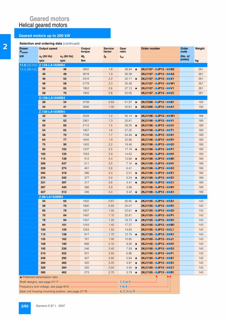
Geared motorsHelical geared motors
Geared motors up to 200 kW
2/66 Siemens D 87.1 · 2007
2
11.0 (50 Hz) Z.128-LA160MB413.2 (60 Hz) 38 46 2802 1.8 38.94 � 2KJ1107 - 7JP13 - 77B2 261
40 48 2618 1.9 36.39 2KJ1107 - 7JP13 - 77A2 261
46 55 2310 2.2 32.11 � 2KJ1107 - 7JP13 - 77X1 261
48 58 2179 2.3 30.28 2KJ1107 - 7JP13 - 77W1 261
54 65 1952 2.6 27.13 � 2KJ1107 - 7JP13 - 77V1 261
58 70 1802 2.8 25.05 2KJ1107 - 7JP13 - 77U1 261
D.108-LA160MB428 34 3739 0.83 51.97 � 2KJ1206 - 7JP13 - 77B1 193
34 41 3066 1.00 42.61 � 2KJ1206 - 7JP13 - 77A1 193
Z.108-LA160MB442 50 2528 1.2 35.14 � 2KJ1106 - 7JP13 - 77W1 189
44 53 2361 1.3 32.81 2KJ1106 - 7JP13 - 77V1 189
50 60 2112 1.5 29.35 � 2KJ1106 - 7JP13 - 77U1 189
54 65 1957 1.6 27.20 2KJ1106 - 7JP13 - 77T1 189
58 70 1794 1.7 24.94 � 2KJ1106 - 7JP13 - 77S1 189
64 77 1645 1.9 22.86 2KJ1106 - 7JP13 - 77R1 189
75 90 1402 2.2 19.48 2KJ1106 - 7JP13 - 77Q1 189
85 102 1237 2.5 17.19 � 2KJ1106 - 7JP13 - 77P1 189
100 120 1053 2.9 14.63 2KJ1106 - 7JP13 - 77N1 189
115 138 912 3.4 12.68 � 2KJ1106 - 7JP13 - 77M1 189
206 247 511 3.5 7.10 � 2KJ1106 - 7JP13 - 77H1 189
228 274 461 3.8 6.41 2KJ1106 - 7JP13 - 77G1 189
265 318 396 4.3 5.51 � 2KJ1106 - 7JP13 - 77E1 189
279 335 377 3.0 5.24 � 2KJ1106 - 7JP13 - 77D1 189
331 397 317 3.6 4.41 � 2KJ1106 - 7JP13 - 77C1 189
367 440 286 3.9 3.98 2KJ1106 - 7JP13 - 77B1 189
427 512 246 4.4 3.42 � 2KJ1106 - 7JP13 - 77A1 189
Z.88-LA160MB454 65 1932 0.87 26.85 � 2KJ1105 - 7JP13 - 77S1 143
58 70 1800 0.93 25.01 2KJ1105 - 7JP13 - 77R1 143
65 78 1627 1.00 22.61 � 2KJ1105 - 7JP13 - 77Q1 143
70 84 1497 1.10 20.81 2KJ1105 - 7JP13 - 77P1 143
78 94 1347 1.20 18.72 � 2KJ1105 - 7JP13 - 77N1 143
84 101 1243 1.40 17.27 2KJ1105 - 7JP13 - 77M1 143
100 120 1053 1.50 14.63 2KJ1105 - 7JP13 - 77L1 143
115 138 917 1.70 12.75 � 2KJ1105 - 7JP13 - 77K1 143
135 162 781 1.90 10.85 2KJ1105 - 7JP13 - 77J1 143
158 190 666 2.10 9.26 � 2KJ1105 - 7JP13 - 77H1 143
192 230 546 2.40 7.59 � 2KJ1105 - 7JP13 - 77G1 143
210 252 501 2.50 6.96 2KJ1105 - 7JP13 - 77F1 143
246 295 427 2.80 5.94 � 2KJ1105 - 7JP13 - 77E1 143
300 360 350 3.20 4.87 � 2KJ1105 - 7JP13 - 77D1 143
328 394 320 2.50 4.45 � 2KJ1105 - 7JP13 - 77C1 143
385 462 273 2.70 3.79 � 2KJ1105 - 7JP13 - 77B1 143
Selection and ordering data (continued)
PowerPmotor
Output speed Output torque
Service factor
Gear ratio
Order number Order code
Weight
kW n2 (50 Hz) n2 (60 Hz) M2 fB itot (No. of poles)rpm rpm Nm kg
� Preferred transmission ratio
Shaft designs, see page 2/117 –––––––––––––––––––––––––––––––––––––––––– 1, 2 or 9 –––––––––––––––––––
Frequency and voltage, see page 8/15 ––––––––––––––––––––––––––––––––––– 1 to 9 ––––––––––––––––––––––––––––––
Gear unit housing mounting position, see page 2/116 –––––––––––––––––––––– A, F, H or R ––––––––––––––––––––––––––

Geared motorsHelical geared motors
Geared motors up to 200 kW
2/67Siemens D 87.1 · 2007
2
11.0 (50 Hz) Z.88-LA160MB413.2 (60 Hz) 469 563 224 2.9 3.11 � 2KJ1105 - 7JP13 - 77A1 143
Z.68-LA160MB4107 128 978 0.82 13.59 2KJ1104 - 7JP13 - 77J1 111
128 154 820 0.96 11.40 2KJ1104 - 7JP13 - 77H1 111
150 180 700 1.10 9.73 � 2KJ1104 - 7JP13 - 77G1 111
180 216 584 1.20 8.11 2KJ1104 - 7JP13 - 77F1 111
217 260 484 1.30 6.72 � 2KJ1104 - 7JP13 - 77E1 111
246 295 427 1.10 5.93 2KJ1104 - 7JP13 - 77D1 111
289 347 364 1.30 5.06 � 2KJ1104 - 7JP13 - 77C1 111
346 415 304 1.50 4.22 2KJ1104 - 7JP13 - 77B1 111
418 502 251 1.70 3.49 � 2KJ1104 - 7JP13 - 77A1 111
E.148-LA160MB4144 173 729 1.1 10.13 � 2KJ1007 - 7JP13 - 77Q1 192
154 185 681 1.4 9.47 2KJ1007 - 7JP13 - 77P1 192
173 208 606 1.7 8.42 � 2KJ1007 - 7JP13 - 77N1 192
184 221 572 1.9 7.95 2KJ1007 - 7JP13 - 77M1 192
204 245 514 2.2 7.14 � 2KJ1007 - 7JP13 - 77L1 192
223 268 471 2.4 6.55 2KJ1007 - 7JP13 - 77K1 192
258 310 407 3.3 5.65 2KJ1007 - 7JP13 - 77J1 192
296 355 355 3.9 4.94 2KJ1007 - 7JP13 - 77H1 192
340 408 309 4.3 4.30 2KJ1007 - 7JP13 - 77G1 192
387 464 271 5.0 3.77 � 2KJ1007 - 7JP13 - 77F1 192
E.128-LA160MB4163 196 643 0.99 8.94 � 2KJ1006 - 7JP13 - 77R1 168
175 210 601 1.20 8.35 2KJ1006 - 7JP13 - 77Q1 168
198 238 530 1.50 7.37 � 2KJ1006 - 7JP13 - 77P1 168
210 252 500 1.80 6.95 2KJ1006 - 7JP13 - 77N1 168
234 281 448 2.10 6.23 � 2KJ1006 - 7JP13 - 77M1 168
254 305 414 2.30 5.75 2KJ1006 - 7JP13 - 77L1 168
297 356 353 2.70 4.91 2KJ1006 - 7JP13 - 77K1 168
329 395 319 3.10 4.44 � 2KJ1006 - 7JP13 - 77J1 168
341 409 308 3.20 4.28 2KJ1006 - 7JP13 - 77H1 168
395 474 266 3.80 3.70 2KJ1006 - 7JP13 - 77G1 168
452 542 232 4.30 3.23 � 2KJ1006 - 7JP13 - 77F1 168
529 635 199 5.00 2.76 � 2KJ1006 - 7JP13 - 77E1 168
591 709 178 5.30 2.47 2KJ1006 - 7JP13 - 77D1 168
695 834 151 5.70 2.10 � 2KJ1006 - 7JP13 - 77C1 168
807 968 130 6.10 1.81 2KJ1006 - 7JP13 - 77B1 168
E.108-LA160MB4267 320 393 1.7 5.46 � 2KJ1005 - 7JP13 - 77K1 131
292 350 360 1.9 5.00 2KJ1005 - 7JP13 - 77J1 131
343 412 307 2.3 4.26 2KJ1005 - 7JP13 - 77H1 131
388 466 271 2.2 3.76 � 2KJ1005 - 7JP13 - 77G1 131
456 547 230 3.2 3.20 2KJ1005 - 7JP13 - 77F1 131
Selection and ordering data (continued)
PowerPmotor
Output speed Output torque
Service factor
Gear ratio
Order number Order code
Weight
kW n2 (50 Hz) n2 (60 Hz) M2 fB itot (No. of poles)rpm rpm Nm kg
� Preferred transmission ratio
Shaft designs, see page 2/117 –––––––––––––––––––––––––––––––––––––––––– 1, 2 or 9 –––––––––––––––––––
Frequency and voltage, see page 8/15 ––––––––––––––––––––––––––––––––––– 1 to 9 ––––––––––––––––––––––––––––––
Gear unit housing mounting position, see page 2/116 –––––––––––––––––––––– A, F, H or R ––––––––––––––––––––––––––

Geared motorsHelical geared motors
Geared motors up to 200 kW
2/68 Siemens D 87.1 · 2007
2
11.0 (50 Hz) E.108-LA160MB413.2 (60 Hz) 527 632 199 3.4 2.77 � 2KJ1005 - 7JP13 - 77E1 131
627 752 168 4.1 2.33 � 2KJ1005 - 7JP13 - 77C1 131
692 830 152 4.1 2.11 2KJ1005 - 7JP13 - 77B1 131
807 968 130 4.2 1.81 � 2KJ1005 - 7JP13 - 77A1 131
E.88-LA160MB4286 343 368 1.0 5.11 � 2KJ1004 - 7JP13 - 77J1 110
311 373 338 1.1 4.70 2KJ1004 - 7JP13 - 77H1 110
345 414 304 1.3 4.23 � 2KJ1004 - 7JP13 - 77G1 110
374 449 281 1.4 3.90 2KJ1004 - 7JP13 - 77F1 110
442 530 237 1.9 3.30 2KJ1004 - 7JP13 - 77E1 110
507 608 207 2.1 2.88 � 2KJ1004 - 7JP13 - 77D1 110
596 715 176 2.4 2.45 2KJ1004 - 7JP13 - 77C1 110
699 839 150 2.8 2.09 � 2KJ1004 - 7JP13 - 77B1 110
854 1025 123 2.9 1.71 � 2KJ1004 - 7JP13 - 77A1 110
E.68-LA160MB4390 468 269 0.85 3.74 � 2KJ1003 - 7JP13 - 77H1 93
423 508 248 0.97 3.45 2KJ1003 - 7JP13 - 77G1 93
472 566 222 1.10 3.09 � 2KJ1003 - 7JP13 - 77F1 93
512 614 205 1.20 2.85 2KJ1003 - 7JP13 - 77E1 93
1035 1242 101 1.50 1.41 � 2KJ1003 - 7JP13 - 77A1 93
15 (50 Hz) D.188-LA160L418 (60 Hz) 6.0 7.2 23923 0.84 243.82 2KJ1211 - 7JR13 - 77N1 688
6.6 7.9 21602 0.93 220.17 2KJ1211 - 7JR13 - 77M1 688
7.1 8.5 20245 0.99 206.34 2KJ1211 - 7JR13 - 77L1 688
8.2 9.8 17389 1.20 177.23 � 2KJ1211 - 7JR13 - 77K1 688
9.5 11.4 15024 1.30 153.12 2KJ1211 - 7JR13 - 77J1 688
10.8 13.0 13261 1.50 135.16 2KJ1211 - 7JR13 - 77H1 688
12.0 14.4 11938 1.70 121.67 � 2KJ1211 - 7JR13 - 77G1 688
14.5 17.4 9906 2.00 100.96 � 2KJ1211 - 7JR13 - 77F1 688
15.9 19.1 9033 2.20 92.06 2KJ1211 - 7JR13 - 77E1 688
D.168-LA160L48.2 9.8 17502 0.80 178.38 � 2KJ1210 - 7JR13 - 77L1 543
8.9 10.7 16064 0.87 163.72 2KJ1210 - 7JR13 - 77K1 543
10.3 12.4 13862 1.00 141.28 2KJ1210 - 7JR13 - 77J1 543
11.8 14.2 12126 1.20 123.59 2KJ1210 - 7JR13 - 77H1 543
13.6 16.3 10546 1.30 107.48 2KJ1210 - 7JR13 - 77G1 543
15.5 18.6 9252 1.50 94.30 � 2KJ1210 - 7JR13 - 77F1 543
18.3 22.0 7825 1.80 79.75 � 2KJ1210 - 7JR13 - 77E1 543
20.0 24.0 7100 2.00 72.36 2KJ1210 - 7JR13 - 77D1 543
23.0 28.0 6189 2.30 63.08 � 2KJ1210 - 7JR13 - 77C1 543
Z.168-LA160L431 37 4573 2.20 46.61 2KJ1110 - 7JR13 - 77V1 524
Selection and ordering data (continued)
PowerPmotor
Output speed Output torque
Service factor
Gear ratio
Order number Order code
Weight
kW n2 (50 Hz) n2 (60 Hz) M2 fB itot (No. of poles)rpm rpm Nm kg
� Preferred transmission ratio
Shaft designs, see page 2/117 –––––––––––––––––––––––––––––––––––––––––– 1, 2 or 9 –––––––––––––––––––
Frequency and voltage, see page 8/15 ––––––––––––––––––––––––––––––––––– 1 to 9 ––––––––––––––––––––––––––––––
Gear unit housing mounting position, see page 2/116 –––––––––––––––––––––– A, F, H or R ––––––––––––––––––––––––––

Geared motorsHelical geared motors
Geared motors up to 200 kW
2/69Siemens D 87.1 · 2007
2
15 (50 Hz) D.148-LA160L418 (60 Hz) 15.7 18.8 9116 0.88 92.91 2KJ1208 - 7JR13 - 77G1 372
18.0 22.0 7951 1.00 81.04 � 2KJ1208 - 7JR13 - 77F1 372
21.0 25.0 6805 1.20 69.36 � 2KJ1208 - 7JR13 - 77E1 372
24.0 29.0 6095 1.30 62.12 2KJ1208 - 7JR13 - 77D1 372
Z.148-LA160L427 32 5322 1.5 54.24 � 2KJ1108 - 7JR13 - 77A2 360
29 35 4978 1.6 50.74 2KJ1108 - 7JR13 - 77X1 360
32 38 4426 1.8 45.11 � 2KJ1108 - 7JR13 - 77W1 360
34 41 4179 1.9 42.59 2KJ1108 - 7JR13 - 77V1 360
38 46 3751 2.1 38.23 � 2KJ1108 - 7JR13 - 77U1 360
42 50 3443 2.3 35.09 2KJ1108 - 7JR13 - 77T1 360
48 58 2971 2.7 30.28 2KJ1108 - 7JR13 - 77S1 360
D.128-LA160L425 30 5648 0.9 57.56 � 2KJ1207 - 7JR13 - 77D1 282
30 36 4753 1.1 48.44 � 2KJ1207 - 7JR13 - 77C1 282
33 40 4289 1.2 43.71 2KJ1207 - 7JR13 - 77B1 282
Z.128-LA160L438 46 3821 1.3 38.94 � 2KJ1107 - 7JR13 - 77B2 273
40 48 3570 1.4 36.39 2KJ1107 - 7JR13 - 77A2 273
46 55 3151 1.6 32.11 � 2KJ1107 - 7JR13 - 77X1 273
48 58 2971 1.7 30.28 2KJ1107 - 7JR13 - 77W1 273
54 65 2662 1.9 27.13 � 2KJ1107 - 7JR13 - 77V1 273
58 70 2458 2.1 25.05 2KJ1107 - 7JR13 - 77U1 273
68 82 2101 2.4 21.41 2KJ1107 - 7JR13 - 77T1 273
76 91 1899 2.7 19.35 � 2KJ1107 - 7JR13 - 77S1 273
78 94 1829 2.8 18.64 2KJ1107 - 7JR13 - 77R1 273
91 109 1582 3.2 16.12 2KJ1107 - 7JR13 - 77Q1 273
104 125 1380 3.5 14.06 � 2KJ1107 - 7JR13 - 77P1 273
200 240 715 3.6 7.29 � 2KJ1107 - 7JR13 - 77J1 273
234 281 612 4.1 6.24 � 2KJ1107 - 7JR13 - 77H1 273
261 313 548 4.8 5.59 � 2KJ1107 - 7JR13 - 77F1 273
Z.108-LA160L442 50 3448 0.90 35.14 � 2KJ1106 - 7JR13 - 77W1 201
44 53 3219 0.96 32.81 2KJ1106 - 7JR13 - 77V1 201
50 60 2880 1.10 29.35 � 2KJ1106 - 7JR13 - 77U1 201
54 65 2669 1.20 27.20 2KJ1106 - 7JR13 - 77T1 201
58 70 2447 1.30 24.94 � 2KJ1106 - 7JR13 - 77S1 201
64 77 2243 1.40 22.86 2KJ1106 - 7JR13 - 77R1 201
75 90 1911 1.60 19.48 2KJ1106 - 7JR13 - 77Q1 201
85 102 1687 1.80 17.19 � 2KJ1106 - 7JR13 - 77P1 201
100 120 1435 2.20 14.63 2KJ1106 - 7JR13 - 77N1 201
115 138 1244 2.50 12.68 � 2KJ1106 - 7JR13 - 77M1 201
137 164 1047 3.00 10.67 � 2KJ1106 - 7JR13 - 77L1 201
152 182 944 3.30 9.62 2KJ1106 - 7JR13 - 77K1 201
177 212 811 3.80 8.27 � 2KJ1106 - 7JR13 - 77J1 201
Selection and ordering data (continued)
PowerPmotor
Output speed Output torque
Service factor
Gear ratio
Order number Order code
Weight
kW n2 (50 Hz) n2 (60 Hz) M2 fB itot (No. of poles)rpm rpm Nm kg
� Preferred transmission ratio
Shaft designs, see page 2/117 –––––––––––––––––––––––––––––––––––––––––– 1, 2 or 9 –––––––––––––––––––
Frequency and voltage, see page 8/15 ––––––––––––––––––––––––––––––––––– 1 to 9 ––––––––––––––––––––––––––––––
Gear unit housing mounting position, see page 2/116 –––––––––––––––––––––– A, F, H or R ––––––––––––––––––––––––––
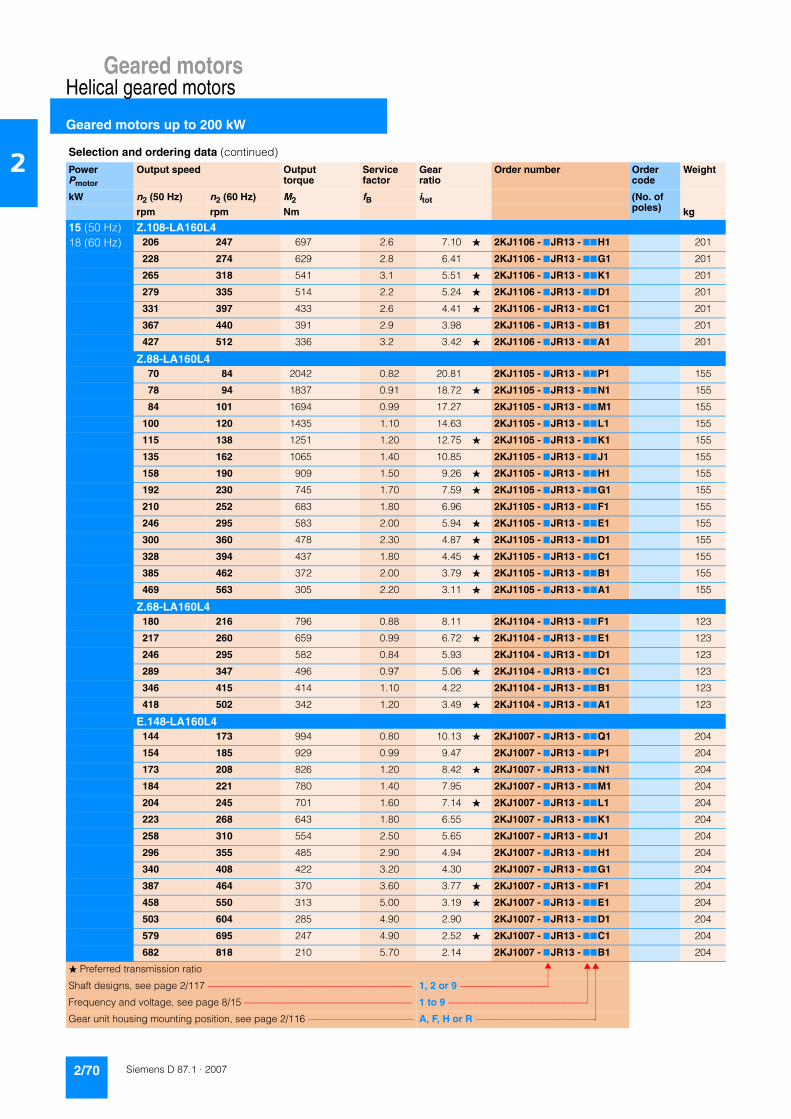
Geared motorsHelical geared motors
Geared motors up to 200 kW
2/70 Siemens D 87.1 · 2007
2
15 (50 Hz) Z.108-LA160L418 (60 Hz) 206 247 697 2.6 7.10 � 2KJ1106 - 7JR13 - 77H1 201
228 274 629 2.8 6.41 2KJ1106 - 7JR13 - 77G1 201
265 318 541 3.1 5.51 � 2KJ1106 - 7JR13 - 77K1 201
279 335 514 2.2 5.24 � 2KJ1106 - 7JR13 - 77D1 201
331 397 433 2.6 4.41 � 2KJ1106 - 7JR13 - 77C1 201
367 440 391 2.9 3.98 2KJ1106 - 7JR13 - 77B1 201
427 512 336 3.2 3.42 � 2KJ1106 - 7JR13 - 77A1 201
Z.88-LA160L470 84 2042 0.82 20.81 2KJ1105 - 7JR13 - 77P1 155
78 94 1837 0.91 18.72 � 2KJ1105 - 7JR13 - 77N1 155
84 101 1694 0.99 17.27 2KJ1105 - 7JR13 - 77M1 155
100 120 1435 1.10 14.63 2KJ1105 - 7JR13 - 77L1 155
115 138 1251 1.20 12.75 � 2KJ1105 - 7JR13 - 77K1 155
135 162 1065 1.40 10.85 2KJ1105 - 7JR13 - 77J1 155
158 190 909 1.50 9.26 � 2KJ1105 - 7JR13 - 77H1 155
192 230 745 1.70 7.59 � 2KJ1105 - 7JR13 - 77G1 155
210 252 683 1.80 6.96 2KJ1105 - 7JR13 - 77F1 155
246 295 583 2.00 5.94 � 2KJ1105 - 7JR13 - 77E1 155
300 360 478 2.30 4.87 � 2KJ1105 - 7JR13 - 77D1 155
328 394 437 1.80 4.45 � 2KJ1105 - 7JR13 - 77C1 155
385 462 372 2.00 3.79 � 2KJ1105 - 7JR13 - 77B1 155
469 563 305 2.20 3.11 � 2KJ1105 - 7JR13 - 77A1 155
Z.68-LA160L4180 216 796 0.88 8.11 2KJ1104 - 7JR13 - 77F1 123
217 260 659 0.99 6.72 � 2KJ1104 - 7JR13 - 77E1 123
246 295 582 0.84 5.93 2KJ1104 - 7JR13 - 77D1 123
289 347 496 0.97 5.06 � 2KJ1104 - 7JR13 - 77C1 123
346 415 414 1.10 4.22 2KJ1104 - 7JR13 - 77B1 123
418 502 342 1.20 3.49 � 2KJ1104 - 7JR13 - 77A1 123
E.148-LA160L4144 173 994 0.80 10.13 � 2KJ1007 - 7JR13 - 77Q1 204
154 185 929 0.99 9.47 2KJ1007 - 7JR13 - 77P1 204
173 208 826 1.20 8.42 � 2KJ1007 - 7JR13 - 77N1 204
184 221 780 1.40 7.95 2KJ1007 - 7JR13 - 77M1 204
204 245 701 1.60 7.14 � 2KJ1007 - 7JR13 - 77L1 204
223 268 643 1.80 6.55 2KJ1007 - 7JR13 - 77K1 204
258 310 554 2.50 5.65 2KJ1007 - 7JR13 - 77J1 204
296 355 485 2.90 4.94 2KJ1007 - 7JR13 - 77H1 204
340 408 422 3.20 4.30 2KJ1007 - 7JR13 - 77G1 204
387 464 370 3.60 3.77 � 2KJ1007 - 7JR13 - 77F1 204
458 550 313 5.00 3.19 � 2KJ1007 - 7JR13 - 77E1 204
503 604 285 4.90 2.90 2KJ1007 - 7JR13 - 77D1 204
579 695 247 4.90 2.52 � 2KJ1007 - 7JR13 - 77C1 204
682 818 210 5.70 2.14 2KJ1007 - 7JR13 - 77B1 204
Selection and ordering data (continued)
PowerPmotor
Output speed Output torque
Service factor
Gear ratio
Order number Order code
Weight
kW n2 (50 Hz) n2 (60 Hz) M2 fB itot (No. of poles)rpm rpm Nm kg
� Preferred transmission ratio
Shaft designs, see page 2/117 –––––––––––––––––––––––––––––––––––––––––– 1, 2 or 9 –––––––––––––––––––
Frequency and voltage, see page 8/15 ––––––––––––––––––––––––––––––––––– 1 to 9 ––––––––––––––––––––––––––––––
Gear unit housing mounting position, see page 2/116 –––––––––––––––––––––– A, F, H or R ––––––––––––––––––––––––––

Geared motorsHelical geared motors
Geared motors up to 200 kW
2/71Siemens D 87.1 · 2007
2
15 (50 Hz) E.148-LA160L418 (60 Hz) 890 1068 161 6 1.64 � 2KJ1007 - 7JR13 - 77A1 204
E.128-LA160L4175 210 819 0.87 8.35 2KJ1006 - 7JR13 - 77Q1 180
198 238 723 1.10 7.37 � 2KJ1006 - 7JR13 - 77P1 180
210 252 682 1.30 6.95 2KJ1006 - 7JR13 - 77N1 180
234 281 611 1.50 6.23 � 2KJ1006 - 7JR13 - 77M1 180
254 305 564 1.70 5.75 2KJ1006 - 7JR13 - 77L1 180
297 356 482 2.00 4.91 2KJ1006 - 7JR13 - 77K1 180
329 395 436 2.30 4.44 � 2KJ1006 - 7JR13 - 77J1 180
341 409 420 2.40 4.28 2KJ1006 - 7JR13 - 77H1 180
395 474 363 2.80 3.70 2KJ1006 - 7JR13 - 77G1 180
452 542 317 3.20 3.23 � 2KJ1006 - 7JR13 - 77F1 180
529 635 271 3.70 2.76 � 2KJ1006 - 7JR13 - 77E1 180
591 709 242 3.90 2.47 2KJ1006 - 7JR13 - 77D1 180
695 834 206 4.20 2.10 � 2KJ1006 - 7JR13 - 77C1 180
807 968 178 4.50 1.81 2KJ1006 - 7JR13 - 77B1 180
1074 1289 133 5.10 1.36 � 2KJ1006 - 7JR13 - 77A1 180
E.108-LA160L4267 320 536 1.2 5.46 � 2KJ1005 - 7JR13 - 77K1 143
292 350 491 1.4 5.00 2KJ1005 - 7JR13 - 77J1 143
343 412 418 1.7 4.26 2KJ1005 - 7JR13 - 77H1 143
388 466 369 1.6 3.76 � 2KJ1005 - 7JR13 - 77G1 143
456 547 314 2.4 3.20 2KJ1005 - 7JR13 - 77F1 143
527 632 272 2.5 2.77 � 2KJ1005 - 7JR13 - 77E1 143
627 752 229 3.0 2.33 � 2KJ1005 - 7JR13 - 77C1 143
692 830 207 3.0 2.11 2KJ1005 - 7JR13 - 77B1 143
807 968 178 3.1 1.81 � 2KJ1005 - 7JR13 - 77A1 143
E.88-LA160L4311 373 461 0.83 4.70 2KJ1004 - 7JR13 - 77H1 122
345 414 415 0.96 4.23 � 2KJ1004 - 7JR13 - 77G1 122
374 449 383 1.00 3.90 2KJ1004 - 7JR13 - 77F1 122
442 530 324 1.40 3.30 2KJ1004 - 7JR13 - 77E1 122
507 608 283 1.50 2.88 � 2KJ1004 - 7JR13 - 77D1 122
596 715 240 1.70 2.45 2KJ1004 - 7JR13 - 77C1 122
699 839 205 2.00 2.09 � 2KJ1004 - 7JR13 - 77B1 122
854 1025 168 2.10 1.71 � 2KJ1004 - 7JR13 - 77A1 122
E.68-LA160L4472 566 303 0.82 3.09 � 2KJ1003 - 7JR13 - 77F1 105
512 614 280 0.89 2.85 2KJ1003 - 7JR13 - 77E1 105
18.5 (50 Hz) D.188-LG180MB422.0 (60 Hz) 7.1 8.5 24799 0.81 206.34 2KJ1211 - 7KL13 - 77L1 743
8.3 10.0 21301 0.94 177.23 � 2KJ1211 - 7KL13 - 77K1 743
9.6 11.5 18403 1.10 153.12 2KJ1211 - 7KL13 - 77J1 743
Selection and ordering data (continued)
PowerPmotor
Output speed Output torque
Service factor
Gear ratio
Order number Order code
Weight
kW n2 (50 Hz) n2 (60 Hz) M2 fB itot (No. of poles)rpm rpm Nm kg
� Preferred transmission ratio
Shaft designs, see page 2/117 –––––––––––––––––––––––––––––––––––––––––– 1, 2 or 9 –––––––––––––––––––
Frequency and voltage, see page 8/15 ––––––––––––––––––––––––––––––––––– 1 to 9 ––––––––––––––––––––––––––––––
Gear unit housing mounting position, see page 2/116 –––––––––––––––––––––– A, F, H or R ––––––––––––––––––––––––––

Geared motorsHelical geared motors
Geared motors up to 200 kW
2/72 Siemens D 87.1 · 2007
2
18.5 (50 Hz) D.188-LG180MB422.0 (60 Hz) 10.9 13.1 16244 1.2 135.16 2KJ1211 - 7KL13 - 77H1 743
12.1 14.5 14623 1.4 121.67 � 2KJ1211 - 7KL13 - 77G1 743
14.6 17.5 12134 1.6 100.96 � 2KJ1211 - 7KL13 - 77F1 743
16.0 19.2 11064 1.8 92.06 2KJ1211 - 7KL13 - 77E1 743
18.2 22.0 9708 2.1 80.77 � 2KJ1211 - 7KL13 - 77D1 743
21.0 25.0 8342 2.4 69.41 2KJ1211 - 7KL13 - 77C1 743
Z.188-LG180MB428 34 6292 2.5 52.35 2KJ1111 - 7KL13 - 77P1 709
D.168-LG180MB410.4 12.5 16980 0.82 141.28 2KJ1210 - 7KL13 - 77J1 598
11.9 14.3 14854 0.94 123.59 2KJ1210 - 7KL13 - 77H1 598
13.7 16.4 12918 1.10 107.48 2KJ1210 - 7KL13 - 77G1 598
15.6 18.7 11334 1.20 94.30 � 2KJ1210 - 7KL13 - 77F1 598
18.4 22.0 9585 1.50 79.75 � 2KJ1210 - 7KL13 - 77E1 598
20.0 24.0 8697 1.60 72.36 2KJ1210 - 7KL13 - 77D1 598
23.0 28.0 7581 1.80 63.08 � 2KJ1210 - 7KL13 - 77C1 598
27.0 32.0 6437 2.20 53.56 2KJ1210 - 7KL13 - 77B1 598
Z.168-LG180MB432 38 5602 1.8 46.61 2KJ1110 - 77L13 - 77V1 579
D.148-LG180MB418.1 22 9740 0.82 81.04 � 2KJ1208 - 7KL13 - 77F1 427
21.0 25 8336 0.96 69.36 � 2KJ1208 - 7KL13 - 77E1 427
24.0 29 7466 1.10 62.12 2KJ1208 - 7KL13 - 77D1 427
28.0 34 6323 1.30 52.61 � 2KJ1208 - 7KL13 - 77C1 427
Z.148-LG180MB433 40 5422 1.5 45.11 � 2KJ1108 - 7KL13 - 77W1 415
34 41 5119 1.6 42.59 2KJ1108 - 7KL13 - 77V1 415
38 46 4595 1.7 38.23 � 2KJ1108 - 7KL13 - 77U1 415
42 50 4217 1.9 35.09 2KJ1108 - 7KL13 - 77T1 415
48 58 3639 2.2 30.28 2KJ1108 - 7KL13 - 77S1 415
56 67 3184 2.5 26.49 2KJ1108 - 7KL13 - 77R1 415
64 77 2769 2.9 23.04 2KJ1108 - 7KL13 - 77Q1 415
D.128-LG180MB430 36 5822 0.88 48.44 � 2KJ1207 - 7KL13 - 77C1 337
34 41 5253 0.97 43.71 2KJ1207 - 7KL13 - 77B1 337
39 47 4515 1.10 37.57 � 2KJ1207 - 7KL13 - 77A1 337
Z.128-LG180MB446 55 3859 1.3 32.11 � 2KJ1107 - 7KL13 - 77X1 328
48 58 3639 1.4 30.28 2KJ1107 - 7KL13 - 77W1 328
54 65 3261 1.6 27.13 � 2KJ1107 - 7KL13 - 77V1 328
59 71 3011 1.7 25.05 2KJ1107 - 7KL13 - 77U1 328
69 83 2573 2.0 21.41 2KJ1107 - 7KL13 - 77T1 328
76 91 2326 2.2 19.35 � 2KJ1107 - 7KL13 - 77S1 328
79 95 2240 2.3 18.64 2KJ1107 - 7KL13 - 77R1 328
91 109 1937 2.6 16.12 2KJ1107 - 7KL13 - 77Q1 328
Selection and ordering data (continued)
PowerPmotor
Output speed Output torque
Service factor
Gear ratio
Order number Order code
Weight
kW n2 (50 Hz) n2 (60 Hz) M2 fB itot (No. of poles)rpm rpm Nm kg
� Preferred transmission ratio
Shaft designs, see page 2/117 –––––––––––––––––––––––––––––––––––––––––– 1, 2 or 9 –––––––––––––––––––
Frequency and voltage, see page 8/15 ––––––––––––––––––––––––––––––––––– 1 to 9 ––––––––––––––––––––––––––––––
Gear unit housing mounting position, see page 2/116 –––––––––––––––––––––– A, F, H or R ––––––––––––––––––––––––––
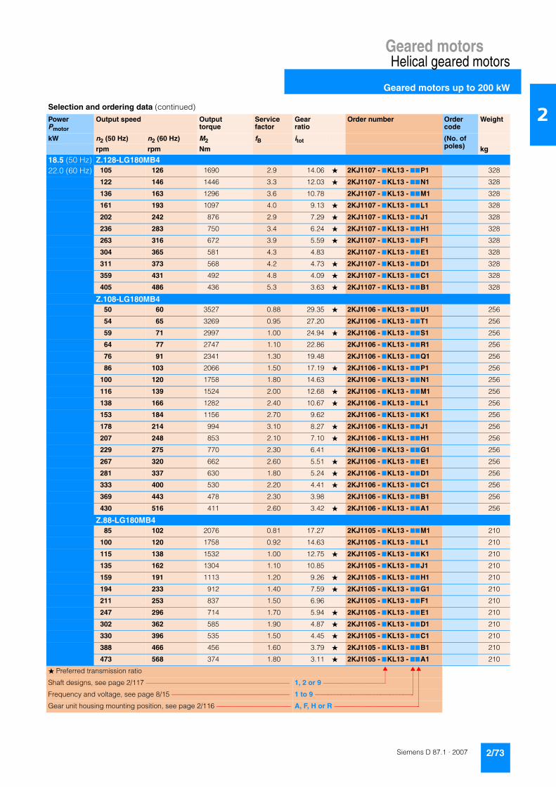
Geared motorsHelical geared motors
Geared motors up to 200 kW
2/73Siemens D 87.1 · 2007
2
18.5 (50 Hz) Z.128-LG180MB422.0 (60 Hz) 105 126 1690 2.9 14.06 � 2KJ1107 - 7KL13 - 77P1 328
122 146 1446 3.3 12.03 � 2KJ1107 - 7KL13 - 77N1 328
136 163 1296 3.6 10.78 2KJ1107 - 7KL13 - 77M1 328
161 193 1097 4.0 9.13 � 2KJ1107 - 7KL13 - 77L1 328
202 242 876 2.9 7.29 � 2KJ1107 - 7KL13 - 77J1 328
236 283 750 3.4 6.24 � 2KJ1107 - 7KL13 - 77H1 328
263 316 672 3.9 5.59 � 2KJ1107 - 7KL13 - 77F1 328
304 365 581 4.3 4.83 2KJ1107 - 7KL13 - 77E1 328
311 373 568 4.2 4.73 � 2KJ1107 - 7KL13 - 77D1 328
359 431 492 4.8 4.09 � 2KJ1107 - 7KL13 - 77C1 328
405 486 436 5.3 3.63 � 2KJ1107 - 7KL13 - 77B1 328
Z.108-LG180MB450 60 3527 0.88 29.35 � 2KJ1106 - 7KL13 - 77U1 256
54 65 3269 0.95 27.20 2KJ1106 - 7KL13 - 77T1 256
59 71 2997 1.00 24.94 � 2KJ1106 - 7KL13 - 77S1 256
64 77 2747 1.10 22.86 2KJ1106 - 7KL13 - 77R1 256
76 91 2341 1.30 19.48 2KJ1106 - 7KL13 - 77Q1 256
86 103 2066 1.50 17.19 � 2KJ1106 - 7KL13 - 77P1 256
100 120 1758 1.80 14.63 2KJ1106 - 7KL13 - 77N1 256
116 139 1524 2.00 12.68 � 2KJ1106 - 7KL13 - 77M1 256
138 166 1282 2.40 10.67 � 2KJ1106 - 7KL13 - 77L1 256
153 184 1156 2.70 9.62 2KJ1106 - 7KL13 - 77K1 256
178 214 994 3.10 8.27 � 2KJ1106 - 7KL13 - 77J1 256
207 248 853 2.10 7.10 � 2KJ1106 - 7KL13 - 77H1 256
229 275 770 2.30 6.41 2KJ1106 - 7KL13 - 77G1 256
267 320 662 2.60 5.51 � 2KJ1106 - 7KL13 - 77E1 256
281 337 630 1.80 5.24 � 2KJ1106 - 7KL13 - 77D1 256
333 400 530 2.20 4.41 � 2KJ1106 - 7KL13 - 77C1 256
369 443 478 2.30 3.98 2KJ1106 - 7KL13 - 77B1 256
430 516 411 2.60 3.42 � 2KJ1106 - 7KL13 - 77A1 256
Z.88-LG180MB485 102 2076 0.81 17.27 2KJ1105 - 7KL13 - 77M1 210
100 120 1758 0.92 14.63 2KJ1105 - 7KL13 - 77L1 210
115 138 1532 1.00 12.75 � 2KJ1105 - 7KL13 - 77K1 210
135 162 1304 1.10 10.85 2KJ1105 - 7KL13 - 77J1 210
159 191 1113 1.20 9.26 � 2KJ1105 - 7KL13 - 77H1 210
194 233 912 1.40 7.59 � 2KJ1105 - 7KL13 - 77G1 210
211 253 837 1.50 6.96 2KJ1105 - 7KL13 - 77F1 210
247 296 714 1.70 5.94 � 2KJ1105 - 7KL13 - 77E1 210
302 362 585 1.90 4.87 � 2KJ1105 - 7KL13 - 77D1 210
330 396 535 1.50 4.45 � 2KJ1105 - 7KL13 - 77C1 210
388 466 456 1.60 3.79 � 2KJ1105 - 7KL13 - 77B1 210
473 568 374 1.80 3.11 � 2KJ1105 - 7KL13 - 77A1 210
Selection and ordering data (continued)
PowerPmotor
Output speed Output torque
Service factor
Gear ratio
Order number Order code
Weight
kW n2 (50 Hz) n2 (60 Hz) M2 fB itot (No. of poles)rpm rpm Nm kg
� Preferred transmission ratio
Shaft designs, see page 2/117 –––––––––––––––––––––––––––––––––––––––––– 1, 2 or 9 –––––––––––––––––––
Frequency and voltage, see page 8/15 ––––––––––––––––––––––––––––––––––– 1 to 9 ––––––––––––––––––––––––––––––
Gear unit housing mounting position, see page 2/116 –––––––––––––––––––––– A, F, H or R ––––––––––––––––––––––––––

Geared motorsHelical geared motors
Geared motors up to 200 kW
2/74 Siemens D 87.1 · 2007
2
18.5 (50 Hz) E.148-LG180MB422.0 (60 Hz) 175 210 1012 0.99 8.42 � 2KJ1007 - 7KL13 - 77N1 259
185 222 955 1.10 7.95 2KJ1007 - 7KL13 - 77M1 259
206 247 858 1.30 7.14 � 2KJ1007 - 7KL13 - 77L1 259
224 269 787 1.50 6.55 2KJ1007 - 7KL13 - 77K1 259
260 312 679 2.00 5.65 2KJ1007 - 7KL13 - 77J1 259
298 358 594 2.40 4.94 2KJ1007 - 7KL13 - 77H1 259
342 410 517 2.60 4.30 2KJ1007 - 7KL13 - 77G1 259
390 468 453 3.00 3.77 � 2KJ1007 - 7KL13 - 77F1 259
461 553 383 4.00 3.19 � 2KJ1007 - 7KL13 - 77E1 259
507 608 349 4.00 2.90 2KJ1007 - 7KL13 - 77D1 259
583 700 303 4.00 2.52 � 2KJ1007 - 7KL13 - 77C1 259
687 824 257 4.70 2.14 2KJ1007 - 7KL13 - 77B1 259
896 1075 197 4.90 1.64 � 2KJ1007 - 7KL13 - 77A1 259
E.128-LG180MB4199 239 886 0.92 7.37 � 2KJ1006 - 7KL13 - 77P1 235
212 254 835 1.10 6.95 2KJ1006 - 7KL13 - 77N1 235
236 283 749 1.20 6.23 � 2KJ1006 - 7KL13 - 77M1 235
256 307 691 1.40 5.75 2KJ1006 - 7KL13 - 77L1 235
299 359 590 1.60 4.91 2KJ1006 - 7KL13 - 77K1 235
331 397 534 1.90 4.44 � 2KJ1006 - 7KL13 - 77J1 235
343 412 514 1.90 4.28 2KJ1006 - 7KL13 - 77H1 235
397 476 445 2.20 3.70 2KJ1006 - 7KL13 - 77G1 235
455 546 388 2.60 3.23 � 2KJ1006 - 7KL13 - 77F1 235
533 640 332 3.00 2.76 � 2KJ1006 - 7KL13 - 77E1 235
595 714 297 3.20 2.47 2KJ1006 - 7KL13 - 77D1 235
700 840 252 3.40 2.10 � 2KJ1006 - 7KL13 - 77C1 235
812 974 218 3.70 1.81 2KJ1006 - 7KL13 - 77B1 235
1081 1297 163 4.20 1.36 � 2KJ1006 - 7KL13 - 77A1 235
E.108-LG180MB4269 323 656 1.0 5.46 � 2KJ1005 - 7KL13 - 77K1 198
294 353 601 1.1 5.00 2KJ1005 - 7KL13 - 77J1 198
345 414 512 1.4 4.26 2KJ1005 - 7KL13 - 77H1 198
391 469 452 1.3 3.76 � 2KJ1005 - 7KL13 - 77G1 198
459 551 385 1.9 3.20 2KJ1005 - 7KL13 - 77F1 198
531 637 333 2.0 2.77 � 2KJ1005 - 7KL13 - 77E1 198
631 757 280 2.4 2.33 � 2KJ1005 - 7KL13 - 77C1 198
697 836 254 2.4 2.11 2KJ1005 - 7KL13 - 77B1 198
812 974 218 2.5 1.81 � 2KJ1005 - 7KL13 - 77A1 198
E.88-LG180MB4377 452 469 0.82 3.90 2KJ1004 - 7KL13 - 77F1 177
445 534 397 1.10 3.30 2KJ1004 - 7KL13 - 77E1 177
510 612 346 1.30 2.88 � 2KJ1004 - 7KL13 - 77D1 177
703 844 251 1.70 2.09 � 2KJ1004 - 7KL13 - 77B1 177
860 1032 206 1.70 1.71 � 2KJ1004 - 7KL13 - 77A1 177
Selection and ordering data (continued)
PowerPmotor
Output speed Output torque
Service factor
Gear ratio
Order number Order code
Weight
kW n2 (50 Hz) n2 (60 Hz) M2 fB itot (No. of poles)rpm rpm Nm kg
� Preferred transmission ratio
Shaft designs, see page 2/117 –––––––––––––––––––––––––––––––––––––––––– 1, 2 or 9 –––––––––––––––––––
Frequency and voltage, see page 8/15 ––––––––––––––––––––––––––––––––––– 1 to 9 ––––––––––––––––––––––––––––––
Gear unit housing mounting position, see page 2/116 –––––––––––––––––––––– A, F, H or R ––––––––––––––––––––––––––

Geared motorsHelical geared motors
Geared motors up to 200 kW
2/75Siemens D 87.1 · 2007
2
22 (50 Hz) D.188-LG180LB426 (60 Hz) 9.6 11.5 21885 0.91 153.12 2KJ1211 - 7KM13 - 77J1 758
10.9 13.1 19318 1.00 135.16 2KJ1211 - 7KM13 - 77H1 758
12.1 14.5 17390 1.20 121.67 � 2KJ1211 - 7KM13 - 77G1 758
14.6 17.5 14430 1.40 100.96 � 2KJ1211 - 7KM13 - 77F1 758
16.0 19.2 13158 1.50 92.06 2KJ1211 - 7KM13 - 77E1 758
18.2 22.0 11544 1.70 80.77 � 2KJ1211 - 7KM13 - 77D1 758
21.0 25.0 9920 2.00 69.41 2KJ1211 - 7KM13 - 77C1 758
Z.188-LG180LB428 34 7482 2.1 52.35 2KJ1111 - 7KM13 - 77P1 724
30 36 6892 2.3 48.22 2KJ1111 - 7KM13 - 77N1 724
D.168-LG180LB413.7 16.4 15362 0.91 107.48 2KJ1210 - 7KM13 - 77G1 613
15.6 18.7 13478 1.00 94.30 � 2KJ1210 - 7KM13 - 77F1 613
18.4 22.0 11398 1.20 79.75 � 2KJ1210 - 7KM13 - 77E1 613
20.0 24.0 10342 1.40 72.36 2KJ1210 - 7KM13 - 77D1 613
23.0 28.0 9016 1.60 63.08 � 2KJ1210 - 7KM13 - 77C1 613
27.0 32.0 7655 1.80 53.56 2KJ1210 - 7KM13 - 77B1 613
Z.168-LG180LB432 38 6662 1.5 46.61 2KJ1110 - 7KM13 - 77V1 594
35 42 6016 2.3 42.09 2KJ1110 - 7KM13 - 77U1 594
37 44 5638 2.5 39.45 2KJ1110 - 7KM13 - 77T1 594
D.148-LG180LB421 25 9913 0.81 69.36 � 2KJ1208 - 7KM13 - 77E1 442
24 29 8879 0.90 62.12 2KJ1208 - 7KM13 - 77D1 442
28 34 7519 1.10 52.61 � 2KJ1208 - 7KM13 - 77C1 442
Z.148-LG180LB433 40 6447 1.2 45.11 � 2KJ1108 - 7KM13 - 77W1 430
34 41 6087 1.3 42.59 2KJ1108 - 7KM13 - 77V1 430
38 46 5464 1.5 38.23 � 2KJ1108 - 7KM13 - 77U1 430
42 50 5015 1.6 35.09 2KJ1108 - 7KM13 - 77T1 430
48 58 4328 1.8 30.28 2KJ1108 - 7KM13 - 77S1 430
56 67 3786 2.1 26.49 2KJ1108 - 7KM13 - 77R1 430
64 77 3293 2.4 23.04 2KJ1108 - 7KM13 - 77Q1 430
73 88 2889 2.8 20.21 � 2KJ1108 - 7KM13 - 77P1 430
86 103 2443 3.3 17.09 � 2KJ1108 - 7KM13 - 77N1 430
170 204 1235 3.9 8.64 � 2KJ1108 - 7KM13 - 77H1 430
188 226 1121 4.3 7.84 2KJ1108 - 7KM13 - 77G1 430
D.128-LG180LB434 41 6247 0.82 43.71 2KJ1207 - 7KM13 - 77B1 352
39 47 5370 0.95 37.57 � 2KJ1207 - 7KM13 - 77A1 352
Z.128-LG180LB446 55 4589 1.1 32.11 � 2KJ1107 - 7KM13 - 77X1 343
48 58 4328 1.2 30.28 2KJ1107 - 7KM13 - 77W1 343
54 65 3878 1.3 27.13 � 2KJ1107 - 7KM13 - 77V1 343
59 71 3580 1.4 25.05 2KJ1107 - 7KM13 - 77U1 343
Selection and ordering data (continued)
PowerPmotor
Output speed Output torque
Service factor
Gear ratio
Order number Order code
Weight
kW n2 (50 Hz) n2 (60 Hz) M2 fB itot (No. of poles)rpm rpm Nm kg
� Preferred transmission ratio
Shaft designs, see page 2/117 –––––––––––––––––––––––––––––––––––––––––– 1, 2 or 9 –––––––––––––––––––
Frequency and voltage, see page 8/15 ––––––––––––––––––––––––––––––––––– 1 to 9 ––––––––––––––––––––––––––––––
Gear unit housing mounting position, see page 2/116 –––––––––––––––––––––– A, F, H or R ––––––––––––––––––––––––––

Geared motorsHelical geared motors
Geared motors up to 200 kW
2/76 Siemens D 87.1 · 2007
2
22 (50 Hz) Z.128-LG180LB426 (60 Hz) 69 83 3060 1.7 21.41 2KJ1107 - 7KM13 - 77T1 343
76 91 2766 1.8 19.35 � 2KJ1107 - 7KM13 - 77S1 343
79 95 2664 1.9 18.64 2KJ1107 - 7KM13 - 77R1 343
91 109 2304 2.2 16.12 2KJ1107 - 7KM13 - 77Q1 343
105 126 2010 2.4 14.06 � 2KJ1107 - 7KM13 - 77P1 343
122 146 1719 2.7 12.03 � 2KJ1107 - 7KM13 - 77N1 343
136 163 1541 3.0 10.78 2KJ1107 - 7KM13 - 77M1 343
161 193 1305 3.4 9.13 � 2KJ1107 - 7KM13 - 77L1 343
187 224 1126 3.8 7.88 2KJ1107 - 7KM13 - 77K1 343
202 242 1042 2.4 7.29 � 2KJ1107 - 7KM13 - 77J1 343
236 283 892 2.8 6.24 � 2KJ1107 - 7KM13 - 77H1 343
248 298 848 4.6 5.93 � 2KJ1107 - 7KM13 - 77G1 343
263 316 799 3.3 5.59 � 2KJ1107 - 7KM13 - 77F1 343
304 365 690 3.6 4.83 2KJ1107 - 7KM13 - 77E1 343
311 373 676 3.5 4.73 � 2KJ1107 - 7KM13 - 77D1 343
359 431 585 4.0 4.09 � 2KJ1107 - 7KM13 - 77C1 343
405 486 519 4.5 3.63 � 2KJ1107 - 7KM13 - 77B1 343
479 575 439 5.1 3.07 � 2KJ1107 - 7KM13 - 77A1 343
Z.108-LG180LB454 65 3888 0.80 27.20 2KJ1106 - 7KM13 - 77T1 271
59 71 3565 0.87 24.94 � 2KJ1106 - 7KM13 - 77S1 271
64 77 3267 0.95 22.86 2KJ1106 - 7KM13 - 77R1 271
76 91 2784 1.10 19.48 2KJ1106 - 7KM13 - 77Q1 271
86 103 2457 1.30 17.19 � 2KJ1106 - 7KM13 - 77P1 271
100 120 2091 1.50 14.63 2KJ1106 - 7KM13 - 77N1 271
116 139 1812 1.70 12.68 � 2KJ1106 - 7KM13 - 77M1 271
138 166 1525 2.00 10.67 � 2KJ1106 - 7KM13 - 77L1 271
153 184 1375 2.30 9.62 2KJ1106 - 7KM13 - 77K1 271
178 214 1182 2.60 8.27 � 2KJ1106 - 7KM13 - 77J1 271
207 248 1015 1.80 7.10 � 2KJ1106 - 7KM13 - 77H1 271
229 275 916 1.90 6.41 2KJ1106 - 7KM13 - 77G1 271
267 320 788 2.20 5.51 � 2KJ1106 - 7KM13 - 77E1 271
281 337 749 1.50 5.24 � 2KJ1106 - 7KM13 - 77D1 271
333 400 630 1.80 4.41 � 2KJ1106 - 7KM13 - 77C1 271
369 443 569 2.00 3.98 2KJ1106 - 7KM13 - 77B1 271
430 516 489 2.20 3.42 � 2KJ1106 - 7KM13 - 77A1 271
Z.88-LG180LB4115 138 1822 0.85 12.75 � 2KJ1105 - 7KM13 - 77K1 225
135 162 1551 0.95 10.85 2KJ1105 - 7KM13 - 77J1 225
159 191 1323 1.10 9.26 � 2KJ1105 - 7KM13 - 77H1 225
194 233 1085 1.20 7.59 � 2KJ1105 - 7KM13 - 77G1 225
211 253 995 1.30 6.96 2KJ1105 - 7KM13 - 77F1 225
247 296 849 1.40 5.94 � 2KJ1105 - 7KM13 - 77E1 225
302 362 696 1.60 4.87 � 2KJ1105 - 7KM13 - 77D1 225
Selection and ordering data (continued)
PowerPmotor
Output speed Output torque
Service factor
Gear ratio
Order number Order code
Weight
kW n2 (50 Hz) n2 (60 Hz) M2 fB itot (No. of poles)rpm rpm Nm kg
� Preferred transmission ratio
Shaft designs, see page 2/117 –––––––––––––––––––––––––––––––––––––––––– 1, 2 or 9 –––––––––––––––––––
Frequency and voltage, see page 8/15 ––––––––––––––––––––––––––––––––––– 1 to 9 ––––––––––––––––––––––––––––––
Gear unit housing mounting position, see page 2/116 –––––––––––––––––––––– A, F, H or R ––––––––––––––––––––––––––

Geared motorsHelical geared motors
Geared motors up to 200 kW
2/77Siemens D 87.1 · 2007
2
22 (50 Hz) Z.88-LG180LB426 (60 Hz) 330 396 636 1.3 4.45 � 2KJ1105 - 7KM13 - 77C1 225
388 466 542 1.4 3.79 � 2KJ1105 - 7KM13 - 77B1 225
473 568 444 1.5 3.11 � 2KJ1105 - 7KM13 - 77A1 225
E.148-LG180LB4175 210 1203 0.83 8.42 � 2KJ1007 - 7KM13 - 77N1 274
185 222 1136 0.93 7.95 2KJ1007 - 7KM13 - 77M1 274
206 247 1020 1.10 7.14 � 2KJ1007 - 7KM13 - 77L1 274
224 269 936 1.20 6.55 2KJ1007 - 7KM13 - 77K1 274
260 312 808 1.70 5.65 2KJ1007 - 7KM13 - 77J1 274
298 358 706 2.00 4.94 2KJ1007 - 7KM13 - 77H1 274
342 410 615 2.20 4.30 2KJ1007 - 7KM13 - 77G1 274
390 468 539 2.50 3.77 � 2KJ1007 - 7KM13 - 77F1 274
461 553 456 3.40 3.19 � 2KJ1007 - 7KM13 - 77E1 274
507 608 414 3.40 2.90 2KJ1007 - 7KM13 - 77D1 274
583 700 360 3.40 2.52 � 2KJ1007 - 7KM13 - 77C1 274
687 824 306 3.90 2.14 2KJ1007 - 7KM13 - 77B1 274
896 1075 234 4.10 1.64 � 2KJ1007 - 7KM13 - 77A1 274
E.128-LG180LB4212 254 993 0.89 6.95 2KJ1006 - 7KM13 - 77N1 250
236 283 890 1.00 6.23 � 2KJ1006 - 7KM13 - 77M1 250
256 307 822 1.20 5.75 2KJ1006 - 7KM13 - 77L1 250
299 359 702 1.40 4.91 2KJ1006 - 7KM13 - 77K1 250
331 397 635 1.60 4.44 � 2KJ1006 - 7KM13 - 77J1 250
343 412 612 1.60 4.28 2KJ1006 - 7KM13 - 77H1 250
397 476 529 1.90 3.70 2KJ1006 - 7KM13 - 77G1 250
455 546 462 2.20 3.23 � 2KJ1006 - 7KM13 - 77F1 250
533 640 394 2.50 2.76 � 2KJ1006 - 7KM13 - 77E1 250
595 714 353 2.70 2.47 2KJ1006 - 7KM13 - 77D1 250
700 840 300 2.90 2.10 � 2KJ1006 - 7KM13 - 77C1 250
812 974 259 3.10 1.81 2KJ1006 - 7KM13 - 77B1 250
1081 1297 194 3.50 1.36 � 2KJ1006 - 7KM13 - 77A1 250
E.108-LG180LB4269 323 780 0.85 5.46 � 2KJ1005 - 7KM13 - 77K1 213
294 353 715 0.95 5.00 2KJ1005 - 7KM13 - 77J1 213
345 414 609 1.20 4.26 2KJ1005 - 7KM13 - 77H1 213
391 469 537 1.10 3.76 � 2KJ1005 - 7KM13 - 77G1 213
459 551 457 1.60 3.20 2KJ1005 - 7KM13 - 77F1 213
531 637 396 1.70 2.77 � 2KJ1005 - 7KM13 - 77E1 213
631 757 333 2.00 2.33 � 2KJ1005 - 7KM13 - 77C1 213
697 836 302 2.10 2.11 2KJ1005 - 7KM13 - 77B1 213
812 974 259 2.10 1.81 � 2KJ1005 - 7KM13 - 77A1 213
E.88-LG180LB4445 534 472 0.95 3.30 2KJ1004 - 7KM13 - 77E1 192
510 612 412 1.10 2.88 � 2KJ1004 - 7KM13 - 77D1 192
860 1032 244 1.50 1.71 � 2KJ1004 - 7KM13 - 77A1 192
Selection and ordering data (continued)
PowerPmotor
Output speed Output torque
Service factor
Gear ratio
Order number Order code
Weight
kW n2 (50 Hz) n2 (60 Hz) M2 fB itot (No. of poles)rpm rpm Nm kg
� Preferred transmission ratio
Shaft designs, see page 2/117 –––––––––––––––––––––––––––––––––––––––––– 1, 2 or 9 –––––––––––––––––––
Frequency and voltage, see page 8/15 ––––––––––––––––––––––––––––––––––– 1 to 9 ––––––––––––––––––––––––––––––
Gear unit housing mounting position, see page 2/116 –––––––––––––––––––––– A, F, H or R ––––––––––––––––––––––––––

Geared motorsHelical geared motors
Geared motors up to 200 kW
2/78 Siemens D 87.1 · 2007
2
30 (50 Hz) D.188-LG200LB436 (60 Hz) 12.1 14.5 23713 0.84 121.67 � 2KJ1211 - 7LK13 - 77G1 808
14.6 17.5 19677 1.00 100.96 � 2KJ1211 - 7LK13 - 77F1 808
16.0 19.2 17942 1.10 92.06 2KJ1211 - 7LK13 - 77E1 808
18.2 22.0 15742 1.30 80.77 � 2KJ1211 - 7LK13 - 77D1 808
21.0 25.0 13528 1.50 69.41 2KJ1211 - 7LK13 - 77C1 808
27.0 32.0 10536 1.90 54.06 � 2KJ1211 - 7LK13 - 77B1 808
34.0 41.0 8371 2.40 42.95 � 2KJ1211 - 7LK13 - 77A1 808
Z.188-LG200LB428 34 10203 1.5 52.35 2KJ1111 - 7LK13 - 77P1 774
30 36 9398 1.7 48.22 2KJ1111 - 7LK13 - 77N1 774
35 42 8156 2.0 41.85 � 2KJ1111 - 7LK13 - 77M1 774
40 48 7190 2.3 36.89 2KJ1111 - 7LK13 - 77L1 774
D.168-LG200LB418.4 22 15543 0.90 79.75 � 2KJ1210 - 7LK13 - 77E1 663
20.0 24 14103 0.99 72.36 2KJ1210 - 7LK13 - 77D1 663
23.0 28 12294 1.10 63.08 � 2KJ1210 - 7LK13 - 77C1 663
27.0 32 10439 1.30 53.56 2KJ1210 - 7LK13 - 77B1 663
Z.168-LG200LB432 38 9084 1.1 46.61 2KJ1110 - 7LK13 - 77V1 644
35 42 8203 1.7 42.09 2KJ1110 - 7LK13 - 77U1 644
37 44 7689 1.8 39.45 2KJ1110 - 7LK13 - 77T1 644
43 52 6603 2.1 33.88 � 2KJ1110 - 7LK13 - 77S1 644
50 60 5705 2.5 29.27 2KJ1110 - 7LK13 - 77Q1 644
57 68 5036 2.8 25.84 2KJ1110 - 7LK13 - 77P1 644
Z.148-LG200LB433 40 8792 0.91 45.11 � 2KJ1108 - 7LK13 - 77W1 480
34 41 8301 0.96 42.59 2KJ1108 - 7LK13 - 77V1 480
38 46 7451 1.10 38.23 � 2KJ1108 - 7LK13 - 77U1 480
42 50 6839 1.20 35.09 2KJ1108 - 7LK13 - 77T1 480
48 58 5902 1.40 30.28 2KJ1108 - 7LK13 - 77S1 480
56 67 5163 1.50 26.49 2KJ1108 - 7LK13 - 77R1 480
64 77 4490 1.80 23.04 2KJ1108 - 7LK13 - 77Q1 480
73 88 3939 2.00 20.21 � 2KJ1108 - 7LK13 - 77P1 480
86 103 3331 2.40 17.09 � 2KJ1108 - 7LK13 - 77N1 480
95 114 3023 2.60 15.51 2KJ1108 - 7LK13 - 77M1 480
109 131 2635 3.00 13.52 � 2KJ1108 - 7LK13 - 77L1 480
128 154 2237 3.60 11.48 2KJ1108 - 7LK13 - 77K1 480
170 204 1684 2.90 8.64 � 2KJ1108 - 7LK13 - 77H1 480
188 226 1528 3.10 7.84 2KJ1108 - 7LK13 - 77G1 480
194 233 1475 3.80 7.57 � 2KJ1108 - 7LK13 - 77F1 480
215 258 1333 3.60 6.84 � 2KJ1108 - 7LK13 - 77E1 480
229 275 1253 4.30 6.43 2KJ1108 - 7LK13 - 77D1 480
253 304 1130 3.70 5.80 2KJ1108 - 7LK13 - 77C1 480
331 397 865 4.40 4.44 � 2KJ1108 - 7LK13 - 77A1 480
Selection and ordering data (continued)
PowerPmotor
Output speed Output torque
Service factor
Gear ratio
Order number Order code
Weight
kW n2 (50 Hz) n2 (60 Hz) M2 fB itot (No. of poles)rpm rpm Nm kg
� Preferred transmission ratio
Shaft designs, see page 2/117 –––––––––––––––––––––––––––––––––––––––––– 1, 2 or 9 –––––––––––––––––––
Frequency and voltage, see page 8/15 ––––––––––––––––––––––––––––––––––– 1 to 9 ––––––––––––––––––––––––––––––
Gear unit housing mounting position, see page 2/116 –––––––––––––––––––––– A, F, H or R ––––––––––––––––––––––––––
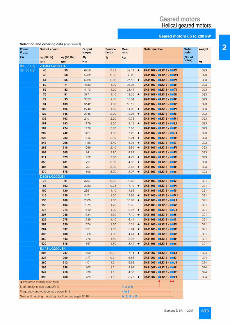
Geared motorsHelical geared motors
Geared motors up to 200 kW
2/79Siemens D 87.1 · 2007
2
30 (50 Hz) Z.128-LG200LB436 (60 Hz) 46 55 6258 0.81 32.11 � 2KJ1107 - 7LK13 - 77X1 393
48 58 5902 0.86 30.28 2KJ1107 - 7LK13 - 77W1 393
54 65 5288 0.96 27.13 � 2KJ1107 - 7LK13 - 77V1 393
59 71 4882 1.00 25.05 2KJ1107 - 7LK13 - 77U1 393
69 83 4173 1.20 21.41 2KJ1107 - 7LK13 - 77T1 393
76 91 3771 1.40 19.35 � 2KJ1107 - 7LK13 - 77S1 393
79 95 3633 1.40 18.64 2KJ1107 - 7LK13 - 77R1 393
91 109 3142 1.60 16.12 2KJ1107 - 7LK13 - 77Q1 393
105 126 2740 1.80 14.06 � 2KJ1107 - 7LK13 - 77P1 393
122 146 2345 2.00 12.03 � 2KJ1107 - 7LK13 - 77N1 393
136 163 2101 2.20 10.78 2KJ1107 - 7LK13 - 77M1 393
161 193 1779 2.50 9.13 � 2KJ1107 - 7LK13 - 77L1 393
187 224 1536 2.80 7.88 2KJ1107 - 7LK13 - 77K1 393
202 242 1421 1.80 7.29 � 2KJ1107 - 7LK13 - 77J1 393
236 283 1216 2.10 6.24 � 2KJ1107 - 7LK13 - 77H1 393
248 298 1156 3.40 5.93 � 2KJ1107 - 7LK13 - 77G1 393
263 316 1089 2.40 5.59 � 2KJ1107 - 7LK13 - 77F1 393
304 365 941 2.70 4.83 2KJ1107 - 7LK13 - 77E1 393
311 373 922 2.60 4.73 � 2KJ1107 - 7LK13 - 77D1 393
359 431 797 3.00 4.09 � 2KJ1107 - 7LK13 - 77C1 393
405 486 707 3.30 3.63 � 2KJ1107 - 7LK13 - 77B1 393
479 575 598 3.70 3.07 � 2KJ1107 - 7LK13 - 77A1 393
Z.108-LG200LB476 91 3797 0.82 19.48 2KJ1106 - 7LK13 - 77Q1 321
86 103 3350 0.93 17.19 � 2KJ1106 - 7LK13 - 77P1 321
100 120 2851 1.10 14.63 2KJ1106 - 7LK13 - 77N1 321
116 139 2471 1.30 12.68 � 2KJ1106 - 7LK13 - 77M1 321
138 166 2080 1.50 10.67 � 2KJ1106 - 7LK13 - 77L1 321
153 184 1875 1.70 9.62 2KJ1106 - 7LK13 - 77K1 321
178 214 1612 1.90 8.27 � 2KJ1106 - 7LK13 - 77J1 321
207 248 1384 1.30 7.10 � 2KJ1106 - 7LK13 - 77H1 321
229 275 1249 1.40 6.41 2KJ1106 - 7LK13 - 77G1 321
267 320 1074 1.60 5.51 � 2KJ1106 - 7LK13 - 77E1 321
281 337 1021 1.10 5.24 � 2KJ1106 - 7LK13 - 77D1 321
333 400 860 1.30 4.41 � 2KJ1106 - 7LK13 - 77C1 321
369 443 776 1.40 3.98 2KJ1106 - 7LK13 - 77B1 321
430 516 667 1.60 3.42 � 2KJ1106 - 7LK13 - 77A1 321
E.148-LG200LB4206 247 1392 0.8 7.14 � 2KJ1007 - 7LK13 - 77L1 324
224 269 1277 0.9 6.55 2KJ1007 - 7LK13 - 77K1 324
260 312 1101 1.2 5.65 2KJ1007 - 7LK13 - 77J1 324
298 358 963 1.5 4.94 2KJ1007 - 7LK13 - 77H1 324
342 410 838 1.6 4.30 2KJ1007 - 7LK13 - 77G1 324
390 468 735 1.8 3.77 � 2KJ1007 - 7LK13 - 77F1 324
Selection and ordering data (continued)
PowerPmotor
Output speed Output torque
Service factor
Gear ratio
Order number Order code
Weight
kW n2 (50 Hz) n2 (60 Hz) M2 fB itot (No. of poles)rpm rpm Nm kg
� Preferred transmission ratio
Shaft designs, see page 2/117 –––––––––––––––––––––––––––––––––––––––––– 1, 2 or 9 –––––––––––––––––––
Frequency and voltage, see page 8/15 ––––––––––––––––––––––––––––––––––– 1 to 9 ––––––––––––––––––––––––––––––
Gear unit housing mounting position, see page 2/116 –––––––––––––––––––––– A, F, H or R ––––––––––––––––––––––––––
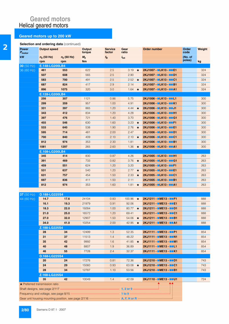
Geared motorsHelical geared motors
Geared motors up to 200 kW
2/80 Siemens D 87.1 · 2007
2
30 (50 Hz) E.148-LG200LB436 (60 Hz) 461 553 622 2.5 3.19 � 2KJ1007 - 7LK13 - 77E1 324
507 608 565 2.5 2.90 2KJ1007 - 7LK13 - 77D1 324
583 700 491 2.5 2.52 � 2KJ1007 - 7LK13 - 77C1 324
687 824 417 2.9 2.14 2KJ1007 - 7LK13 - 77B1 324
896 1075 320 3.0 1.64 � 2KJ1007 - 7LK13 - 77A1 324
E.128-LG200LB4256 307 1121 0.86 5.75 2KJ1006 - 7LK13 - 77L1 300
299 359 957 1.00 4.91 2KJ1006 - 7LK13 - 77K1 300
331 397 865 1.20 4.44 � 2KJ1006 - 7LK13 - 77J1 300
343 412 834 1.20 4.28 2KJ1006 - 7LK13 - 77H1 300
397 476 721 1.40 3.70 2KJ1006 - 7LK13 - 77G1 300
455 546 630 1.60 3.23 � 2KJ1006 - 7LK13 - 77F1 300
533 640 538 1.90 2.76 � 2KJ1006 - 7LK13 - 77E1 300
595 714 481 2.00 2.47 2KJ1006 - 7LK13 - 77D1 300
700 840 409 2.10 2.10 � 2KJ1006 - 7LK13 - 77C1 300
812 974 353 2.30 1.81 2KJ1006 - 7LK13 - 77B1 300
1081 1297 265 2.60 1.36 � 2KJ1006 - 7LK13 - 77A1 300
E.108-LG200LB4345 414 830 0.87 4.26 2KJ1005 - 7LK13 - 77H1 263
391 469 733 0.82 3.76 � 2KJ1005 - 7LK13 - 77G1 263
459 551 624 1.20 3.20 2KJ1005 - 7LK13 - 77F1 263
531 637 540 1.20 2.77 � 2KJ1005 - 7LK13 - 77E1 263
631 757 454 1.50 2.33 � 2KJ1005 - 7LK13 - 77C1 263
697 836 411 1.50 2.11 2KJ1005 - 7LK13 - 77B1 263
812 974 353 1.60 1.81 � 2KJ1005 - 7LK13 - 77A1 263
37 (50 Hz) D.188-LG225S444 (60 Hz) 14.7 17.6 24104 0.83 100.96 � 2KJ1211 - 7ME13 - 77F1 888
16.1 19.3 21979 0.91 92.06 2KJ1211 - 7ME13 - 77E1 888
18.3 22.0 19284 1.00 80.77 � 2KJ1211 - 7ME13 - 77D1 888
21.0 25.0 16572 1.20 69.41 2KJ1211 - 7ME13 - 77C1 888
27.0 32.0 12907 1.50 54.06 � 2KJ1211 - 7ME13 - 77B1 888
34.0 41.0 10254 2.00 42.95 � 2KJ1211 - 7ME13 - 77A1 888
Z.188-LG225S428 34 12499 1.3 52.35 2KJ1111 - 7ME13 - 77P1 854
31 37 11513 1.4 48.22 2KJ1111 - 7ME13 - 77N1 854
35 42 9992 1.6 41.85 � 2KJ1111 - 7ME13 - 77M1 854
40 48 8807 1.9 36.89 2KJ1111 - 7ME13 - 77L1 854
46 55 7728 2.4 32.37 2KJ1111 - 7ME13 - 77K1 854
D.168-LG225S420 24 17276 0.81 72.36 2KJ1210 - 7ME13 - 77D1 743
24 29 15060 0.93 63.08 � 2KJ1210 - 7ME13 - 77C1 743
28 34 12787 1.10 53.56 2KJ1210 - 7ME13 - 77B1 743
Z.168-LG225S435 42 10049 1.4 42.09 2KJ1110 - 7ME13 - 77U1 724
Selection and ordering data (continued)
PowerPmotor
Output speed Output torque
Service factor
Gear ratio
Order number Order code
Weight
kW n2 (50 Hz) n2 (60 Hz) M2 fB itot (No. of poles)rpm rpm Nm kg
� Preferred transmission ratio
Shaft designs, see page 2/117 –––––––––––––––––––––––––––––––––––––––––– 1, 2 or 9 –––––––––––––––––––
Frequency and voltage, see page 8/15 ––––––––––––––––––––––––––––––––––– 1 to 9 ––––––––––––––––––––––––––––––
Gear unit housing mounting position, see page 2/116 –––––––––––––––––––––– A, F, H or R ––––––––––––––––––––––––––

Geared motorsHelical geared motors
Geared motors up to 200 kW
2/81Siemens D 87.1 · 2007
2
37 (50 Hz) Z.168-LG225S444 (60 Hz) 38 46 9419 1.5 39.45 2KJ1110 - 7ME13 - 77T1 724
44 53 8089 1.7 33.88 � 2KJ1110 - 7ME13 - 77S1 724
51 61 6988 2.0 29.27 2KJ1110 - 7ME13 - 77Q1 724
57 68 6169 2.3 25.84 2KJ1110 - 7ME13 - 77P1 724
64 77 5553 2.5 23.26 � 2KJ1110 - 7ME13 - 77N1 724
77 92 4608 3.0 19.30 � 2KJ1110 - 7ME13 - 77M1 724
84 101 4202 3.3 17.60 2KJ1110 - 7ME13 - 77L1 724
160 192 2211 3.6 9.26 � 2KJ1110 - 7ME13 - 77G1 724
206 247 1719 4.1 7.20 � 2KJ1110 - 7ME13 - 77E1 724
Z.148-LG225S439 47 9127 0.88 38.23 � 2KJ1108 - 7ME13 - 77U1 560
42 50 8378 0.95 35.09 2KJ1108 - 7ME13 - 77T1 560
49 59 7229 1.10 30.28 2KJ1108 - 7ME13 - 77S1 560
56 67 6324 1.30 26.49 2KJ1108 - 7ME13 - 77R1 560
64 77 5501 1.50 23.04 2KJ1108 - 7ME13 - 77Q1 560
73 88 4825 1.70 20.21 � 2KJ1108 - 7ME13 - 77P1 560
87 104 4080 2.00 17.09 � 2KJ1108 - 7ME13 - 77N1 560
95 114 3703 2.20 15.51 2KJ1108 - 7ME13 - 77M1 560
109 131 3228 2.50 13.52 � 2KJ1108 - 7ME13 - 77L1 560
129 155 2741 2.90 11.48 2KJ1108 - 7ME13 - 77K1 560
168 202 2099 3.80 8.79 � 2KJ1108 - 7ME13 - 77J1 560
171 205 2063 2.30 8.64 � 2KJ1108 - 7ME13 - 77H1 560
189 227 1872 2.60 7.84 2KJ1108 - 7ME13 - 77G1 560
196 235 1807 3.10 7.57 � 2KJ1108 - 7ME13 - 77F1 560
216 259 1633 2.90 6.84 � 2KJ1108 - 7ME13 - 77E1 560
230 276 1535 3.50 6.43 2KJ1108 - 7ME13 - 77D1 560
255 306 1385 3.00 5.80 2KJ1108 - 7ME13 - 77C1 560
301 361 1175 4.30 4.92 � 2KJ1108 - 7ME13 - 77B1 560
333 400 1060 3.60 4.44 � 2KJ1108 - 7ME13 - 77A1 560
Z.128-LG225S459 71 5981 0.85 25.05 2KJ1107 - 7ME13 - 77U1 473
69 83 5112 1.00 21.41 2KJ1107 - 7ME13 - 77T1 473
76 91 4620 1.10 19.35 � 2KJ1107 - 7ME13 - 77S1 473
79 95 4450 1.10 18.64 2KJ1107 - 7ME13 - 77R1 473
92 110 3849 1.30 16.12 2KJ1107 - 7ME13 - 77Q1 473
105 126 3357 1.50 14.06 � 2KJ1107 - 7ME13 - 77P1 473
123 148 2872 1.60 12.03 � 2KJ1107 - 7ME13 - 77N1 473
137 164 2574 1.80 10.78 2KJ1107 - 7ME13 - 77M1 473
162 194 2180 2.00 9.13 � 2KJ1107 - 7ME13 - 77L1 473
188 226 1881 2.30 7.88 2KJ1107 - 7ME13 - 77K1 473
203 244 1740 1.50 7.29 � 2KJ1107 - 7ME13 - 77J1 473
237 284 1490 1.70 6.24 � 2KJ1107 - 7ME13 - 77H1 473
250 300 1416 2.80 5.93 � 2KJ1107 - 7ME13 - 77G1 473
265 318 1335 2.00 5.59 � 2KJ1107 - 7ME13 - 77F1 473
306 367 1153 2.20 4.83 2KJ1107 - 7ME13 - 77E1 473
Selection and ordering data (continued)
PowerPmotor
Output speed Output torque
Service factor
Gear ratio
Order number Order code
Weight
kW n2 (50 Hz) n2 (60 Hz) M2 fB itot (No. of poles)rpm rpm Nm kg
� Preferred transmission ratio
Shaft designs, see page 2/117 –––––––––––––––––––––––––––––––––––––––––– 1, 2 or 9 –––––––––––––––––––
Frequency and voltage, see page 8/15 ––––––––––––––––––––––––––––––––––– 1 to 9 ––––––––––––––––––––––––––––––
Gear unit housing mounting position, see page 2/116 –––––––––––––––––––––– A, F, H or R ––––––––––––––––––––––––––
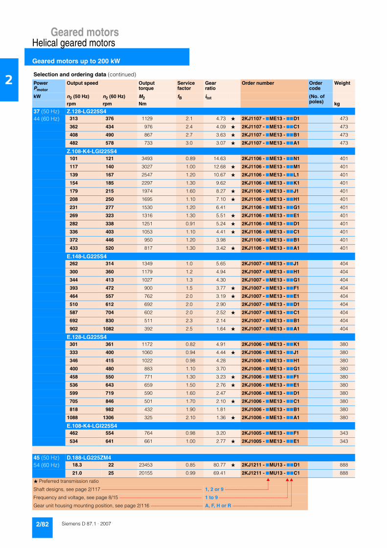
Geared motorsHelical geared motors
Geared motors up to 200 kW
2/82 Siemens D 87.1 · 2007
2
37 (50 Hz) Z.128-LG225S444 (60 Hz) 313 376 1129 2.1 4.73 � 2KJ1107 - 7ME13 - 77D1 473
362 434 976 2.4 4.09 � 2KJ1107 - 7ME13 - 77C1 473
408 490 867 2.7 3.63 � 2KJ1107 - 7ME13 - 77B1 473
482 578 733 3.0 3.07 � 2KJ1107 - 7ME13 - 77A1 473
Z.108-K4-LGI225S4101 121 3493 0.89 14.63 2KJ1106 - 7ME13 - 77N1 401
117 140 3027 1.00 12.68 � 2KJ1106 - 7ME13 - 77M1 401
139 167 2547 1.20 10.67 � 2KJ1106 - 7ME13 - 77L1 401
154 185 2297 1.30 9.62 2KJ1106 - 7ME13 - 77K1 401
179 215 1974 1.60 8.27 � 2KJ1106 - 7ME13 - 77J1 401
208 250 1695 1.10 7.10 � 2KJ1106 - 7ME13 - 77H1 401
231 277 1530 1.20 6.41 2KJ1106 - 7ME13 - 77G1 401
269 323 1316 1.30 5.51 � 2KJ1106 - 7ME13 - 77E1 401
282 338 1251 0.91 5.24 � 2KJ1106 - 7ME13 - 77D1 401
336 403 1053 1.10 4.41 � 2KJ1106 - 7ME13 - 77C1 401
372 446 950 1.20 3.98 2KJ1106 - 7ME13 - 77B1 401
433 520 817 1.30 3.42 � 2KJ1106 - 7ME13 - 77A1 401
E.148-LG225S4262 314 1349 1.0 5.65 2KJ1007 - 7ME13 - 77J1 404
300 360 1179 1.2 4.94 2KJ1007 - 7ME13 - 77H1 404
344 413 1027 1.3 4.30 2KJ1007 - 7ME13 - 77G1 404
393 472 900 1.5 3.77 � 2KJ1007 - 7ME13 - 77F1 404
464 557 762 2.0 3.19 � 2KJ1007 - 7ME13 - 77E1 404
510 612 692 2.0 2.90 2KJ1007 - 7ME13 - 77D1 404
587 704 602 2.0 2.52 � 2KJ1007 - 7ME13 - 77C1 404
692 830 511 2.3 2.14 2KJ1007 - 7ME13 - 77B1 404
902 1082 392 2.5 1.64 � 2KJ1007 - 7ME13 - 77A1 404
E.128-LG225S4301 361 1172 0.82 4.91 2KJ1006 - 7ME13 - 77K1 380
333 400 1060 0.94 4.44 � 2KJ1006 - 7ME13 - 77J1 380
346 415 1022 0.98 4.28 2KJ1006 - 7ME13 - 77H1 380
400 480 883 1.10 3.70 2KJ1006 - 7ME13 - 77G1 380
458 550 771 1.30 3.23 � 2KJ1006 - 7ME13 - 77F1 380
536 643 659 1.50 2.76 � 2KJ1006 - 7ME13 - 77E1 380
599 719 590 1.60 2.47 2KJ1006 - 7ME13 - 77D1 380
705 846 501 1.70 2.10 � 2KJ1006 - 7ME13 - 77C1 380
818 982 432 1.90 1.81 2KJ1006 - 7ME13 - 77B1 380
1088 1306 325 2.10 1.36 � 2KJ1006 - 7ME13 - 77A1 380
E.108-K4-LGI225S4462 554 764 0.98 3.20 2KJ1005 - 7ME13 - 77F1 343
534 641 661 1.00 2.77 � 2KJ1005 - 7ME13 - 77E1 343
45 (50 Hz) D.188-LG225ZM454 (60 Hz) 18.3 22 23453 0.85 80.77 � 2KJ1211 - 7MU13 - 77D1 888
21.0 25 20155 0.99 69.41 2KJ1211 - 7MU13 - 77C1 888
Selection and ordering data (continued)
PowerPmotor
Output speed Output torque
Service factor
Gear ratio
Order number Order code
Weight
kW n2 (50 Hz) n2 (60 Hz) M2 fB itot (No. of poles)rpm rpm Nm kg
� Preferred transmission ratio
Shaft designs, see page 2/117 –––––––––––––––––––––––––––––––––––––––––– 1, 2 or 9 –––––––––––––––––––
Frequency and voltage, see page 8/15 ––––––––––––––––––––––––––––––––––– 1 to 9 ––––––––––––––––––––––––––––––
Gear unit housing mounting position, see page 2/116 –––––––––––––––––––––– A, F, H or R ––––––––––––––––––––––––––
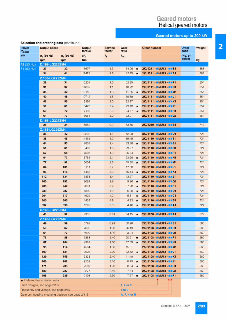
Geared motorsHelical geared motors
Geared motors up to 200 kW
2/83Siemens D 87.1 · 2007
2
45 (50 Hz) D.188-LG225ZM454 (60 Hz) 27 32 15697 1.3 54.06 � 2KJ1211 - 7MU13 - 77B1 888
34 41 12471 1.6 42.95 � 2KJ1211 - 7MU13 - 77A1 888
Z.188-LG225ZM428 34 15201 1.0 52.35 2KJ1111 - 7MU13 - 77P1 854
31 37 14002 1.1 48.22 2KJ1111 - 7MU13 - 77N1 854
35 42 12152 1.3 41.85 � 2KJ1111 - 7MU13 - 77M1 854
40 48 10712 1.5 36.89 2KJ1111 - 7MU13 - 77L1 854
46 55 9399 2.0 32.37 2KJ1111 - 7MU13 - 77K1 854
51 61 8473 2.4 29.18 � 2KJ1111 - 7MU13 - 77J1 854
60 72 7193 2.8 24.77 � 2KJ1111 - 7MU13 - 77H1 854
64 77 6681 3.0 23.01 2KJ1111 - 7MU13 - 77G1 854
D.168-LG225ZM428 34 15552 0.9 53.56 2KJ1210 - 7MU13 - 77B1 743
Z.168-LG225ZM435 42 12222 1.1 42.09 2KJ1110 - 7MU13 - 77U1 724
38 46 11455 1.2 39.45 2KJ1110 - 7MU13 - 77T1 724
44 53 9838 1.4 33.88 � 2KJ1110 - 7MU13 - 77S1 724
51 61 8499 1.6 29.27 2KJ1110 - 7MU13 - 77Q1 724
57 68 7503 1.9 25.84 2KJ1110 - 7MU13 - 77P1 724
64 77 6754 2.1 23.26 � 2KJ1110 - 7MU13 - 77N1 724
77 92 5604 2.5 19.30 � 2KJ1110 - 7MU13 - 77M1 724
84 101 5111 2.7 17.60 2KJ1110 - 7MU13 - 77L1 724
96 115 4483 3.0 15.44 � 2KJ1110 - 7MU13 - 77K1 724
112 134 3853 3.4 13.27 2KJ1110 - 7MU13 - 77J1 724
160 192 2689 2.9 9.26 � 2KJ1110 - 7MU13 - 77G1 724
206 247 2091 3.4 7.20 � 2KJ1110 - 7MU13 - 77E1 724
239 287 1800 4.2 6.20 � 2KJ1110 - 7MU13 - 77D1 724
264 317 1629 4.2 5.61 � 2KJ1110 - 7MU13 - 77C1 724
300 360 1432 4.9 4.93 � 2KJ1110 - 7MU13 - 77B1 724
332 398 1295 5.0 4.46 � 2KJ1110 - 7MU13 - 77A1 724
D.148-LG225ZM443 52 9916 0.81 34.15 � 2KJ1208 - 7MU13 - 77A1 572
Z.148-LG225ZM449 59 8792 0.91 30.28 2KJ1108 - 7MU13 - 77S1 560
56 67 7692 1.00 26.49 2KJ1108 - 7MU13 - 77R1 560
64 77 6690 1.20 23.04 2KJ1108 - 7MU13 - 77Q1 560
73 88 5868 1.40 20.21 � 2KJ1108 - 7MU13 - 77P1 560
87 104 4962 1.60 17.09 � 2KJ1108 - 7MU13 - 77N1 560
95 114 4504 1.80 15.51 2KJ1108 - 7MU13 - 77M1 560
109 131 3926 2.00 13.52 � 2KJ1108 - 7MU13 - 77L1 560
129 155 3333 2.40 11.48 2KJ1108 - 7MU13 - 77K1 560
168 202 2552 3.10 8.79 � 2KJ1108 - 7MU13 - 77J1 560
171 205 2509 1.90 8.64 � 2KJ1108 - 7MU13 - 77H1 560
189 227 2277 2.10 7.84 2KJ1108 - 7MU13 - 77G1 560
196 235 2198 2.50 7.57 � 2KJ1108 - 7MU13 - 77F1 560
Selection and ordering data (continued)
PowerPmotor
Output speed Output torque
Service factor
Gear ratio
Order number Order code
Weight
kW n2 (50 Hz) n2 (60 Hz) M2 fB itot (No. of poles)rpm rpm Nm kg
� Preferred transmission ratio
Shaft designs, see page 2/117 –––––––––––––––––––––––––––––––––––––––––– 1, 2 or 9 –––––––––––––––––––
Frequency and voltage, see page 8/15 ––––––––––––––––––––––––––––––––––– 1 to 9 ––––––––––––––––––––––––––––––
Gear unit housing mounting position, see page 2/116 –––––––––––––––––––––– A, F, H or R ––––––––––––––––––––––––––

Geared motorsHelical geared motors
Geared motors up to 200 kW
2/84 Siemens D 87.1 · 2007
2
45 (50 Hz) Z.148-LG225ZM454 (60 Hz) 216 259 1986 2.4 6.84 � 2KJ1108 - 7MU13 - 77E1 560
230 276 1867 2.9 6.43 2KJ1108 - 7MU13 - 77D1 560
255 306 1684 2.5 5.80 2KJ1108 - 7MU13 - 77C1 560
301 361 1429 3.5 4.92 � 2KJ1108 - 7MU13 - 77B1 560
333 400 1289 3.0 4.44 � 2KJ1108 - 7MU13 - 77A1 560
Z.128-LG225ZM469 83 6217 0.82 21.41 2KJ1107 - 7MU13 - 77T1 473
76 91 5619 0.91 19.35 � 2KJ1107 - 7MU13 - 77S1 473
79 95 5413 0.94 18.64 2KJ1107 - 7MU13 - 77R1 473
92 110 4681 1.10 16.12 2KJ1107 - 7MU13 - 77Q1 473
105 126 4083 1.20 14.06 � 2KJ1107 - 7MU13 - 77P1 473
123 148 3493 1.40 12.03 � 2KJ1107 - 7MU13 - 77N1 473
137 164 3130 1.50 10.78 2KJ1107 - 7MU13 - 77M1 473
162 194 2651 1.70 9.13 � 2KJ1107 - 7MU13 - 77L1 473
188 226 2288 1.90 7.88 2KJ1107 - 7MU13 - 77K1 473
203 244 2117 1.20 7.29 � 2KJ1107 - 7MU13 - 77J1 473
237 284 1812 1.40 6.24 � 2KJ1107 - 7MU13 - 77H1 473
250 300 1722 2.30 5.93 � 2KJ1107 - 7MU13 - 77G1 473
265 318 1623 1.60 5.59 � 2KJ1107 - 7MU13 - 77F1 473
306 367 1402 1.80 4.83 2KJ1107 - 7MU13 - 77E1 473
313 376 1373 1.70 4.73 � 2KJ1107 - 7MU13 - 77D1 473
362 434 1188 2.00 4.09 � 2KJ1107 - 7MU13 - 77C1 473
408 490 1054 2.20 3.63 � 2KJ1107 - 7MU13 - 77B1 473
482 578 891 2.50 3.07 � 2KJ1107 - 7MU13 - 77A1 473
Z.108-K4-LGI225ZM4117 140 3682 0.84 12.68 � 2KJ1106 - 7MU13 - 77M1 401
139 167 3098 1.00 10.67 � 2KJ1106 - 7MU13 - 77L1 401
154 185 2793 1.10 9.62 2KJ1106 - 7MU13 - 77K1 401
179 215 2401 1.30 8.27 � 2KJ1106 - 7MU13 - 77J1 401
208 250 2062 0.87 7.10 � 2KJ1106 - 7MU13 - 77H1 401
231 277 1861 0.95 6.41 2KJ1106 - 7MU13 - 77G1 401
269 323 1600 1.10 5.51 2KJ1106 - 7MU13 - 77E1 401
336 403 1281 0.89 4.41 2KJ1106 - 7MU13 - 77C1 401
372 446 1156 0.97 3.98 2KJ1106 - 7MU13 - 77B1 401
433 520 993 1.10 3.42 � 2KJ1106 - 7MU13 - 77A1 401
E.148-LG225ZM4262 314 1641 0.83 5.65 2KJ1007 - 7MU13 - 77J1 404
300 360 1434 0.98 4.94 2KJ1007 - 7MU13 - 77H1 404
344 413 1249 1.10 4.30 2KJ1007 - 7MU13 - 77G1 404
393 472 1095 1.20 3.77 � 2KJ1007 - 7MU13 - 77F1 404
464 557 926 1.70 3.19 � 2KJ1007 - 7MU13 - 77E1 404
510 612 842 1.70 2.90 2KJ1007 - 7MU13 - 77D1 404
587 704 732 1.70 2.52 � 2KJ1007 - 7MU13 - 77C1 404
692 830 621 1.90 2.14 2KJ1007 - 7MU13 - 77B1 404
902 1082 476 2.00 1.64 � 2KJ1007 - 7MU13 - 77A1 404
Selection and ordering data (continued)
PowerPmotor
Output speed Output torque
Service factor
Gear ratio
Order number Order code
Weight
kW n2 (50 Hz) n2 (60 Hz) M2 fB itot (No. of poles)rpm rpm Nm kg
� Preferred transmission ratio
Shaft designs, see page 2/117 –––––––––––––––––––––––––––––––––––––––––– 1, 2 or 9 –––––––––––––––––––
Frequency and voltage, see page 8/15 ––––––––––––––––––––––––––––––––––– 1 to 9 ––––––––––––––––––––––––––––––
Gear unit housing mounting position, see page 2/116 –––––––––––––––––––––– A, F, H or R ––––––––––––––––––––––––––
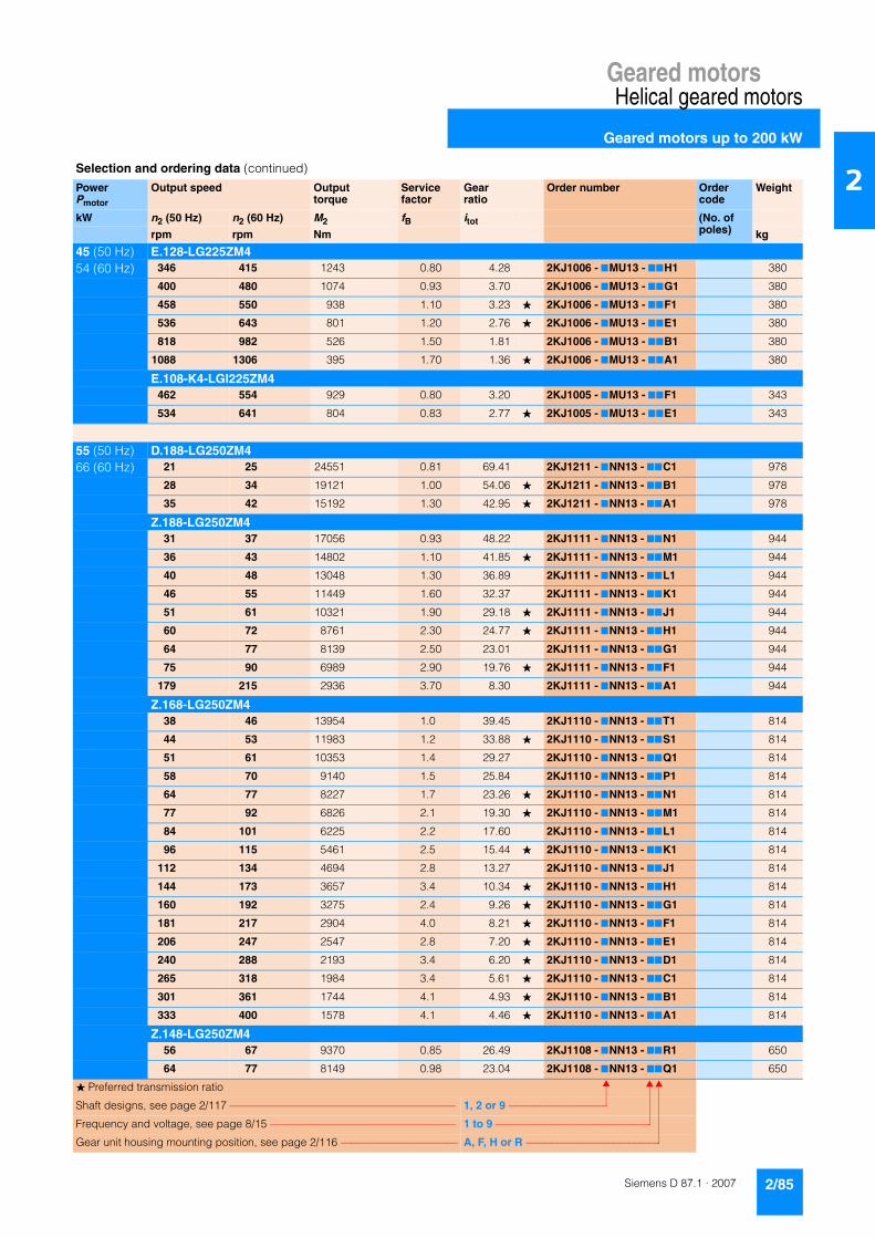
Geared motorsHelical geared motors
Geared motors up to 200 kW
2/85Siemens D 87.1 · 2007
2
45 (50 Hz) E.128-LG225ZM454 (60 Hz) 346 415 1243 0.80 4.28 2KJ1006 - 7MU13 - 77H1 380
400 480 1074 0.93 3.70 2KJ1006 - 7MU13 - 77G1 380
458 550 938 1.10 3.23 � 2KJ1006 - 7MU13 - 77F1 380
536 643 801 1.20 2.76 � 2KJ1006 - 7MU13 - 77E1 380
818 982 526 1.50 1.81 2KJ1006 - 7MU13 - 77B1 380
1088 1306 395 1.70 1.36 � 2KJ1006 - 7MU13 - 77A1 380
E.108-K4-LGI225ZM4462 554 929 0.80 3.20 2KJ1005 - 7MU13 - 77F1 343
534 641 804 0.83 2.77 � 2KJ1005 - 7MU13 - 77E1 343
55 (50 Hz) D.188-LG250ZM466 (60 Hz) 21 25 24551 0.81 69.41 2KJ1211 - 7NN13 - 77C1 978
28 34 19121 1.00 54.06 � 2KJ1211 - 7NN13 - 77B1 978
35 42 15192 1.30 42.95 � 2KJ1211 - 7NN13 - 77A1 978
Z.188-LG250ZM431 37 17056 0.93 48.22 2KJ1111 - 7NN13 - 77N1 944
36 43 14802 1.10 41.85 � 2KJ1111 - 7NN13 - 77M1 944
40 48 13048 1.30 36.89 2KJ1111 - 7NN13 - 77L1 944
46 55 11449 1.60 32.37 2KJ1111 - 7NN13 - 77K1 944
51 61 10321 1.90 29.18 � 2KJ1111 - 7NN13 - 77J1 944
60 72 8761 2.30 24.77 � 2KJ1111 - 7NN13 - 77H1 944
64 77 8139 2.50 23.01 2KJ1111 - 7NN13 - 77G1 944
75 90 6989 2.90 19.76 � 2KJ1111 - 7NN13 - 77F1 944
179 215 2936 3.70 8.30 2KJ1111 - 7NN13 - 77A1 944
Z.168-LG250ZM438 46 13954 1.0 39.45 2KJ1110 - 7NN13 - 77T1 814
44 53 11983 1.2 33.88 � 2KJ1110 - 7NN13 - 77S1 814
51 61 10353 1.4 29.27 2KJ1110 - 7NN13 - 77Q1 814
58 70 9140 1.5 25.84 2KJ1110 - 7NN13 - 77P1 814
64 77 8227 1.7 23.26 � 2KJ1110 - 7NN13 - 77N1 814
77 92 6826 2.1 19.30 � 2KJ1110 - 7NN13 - 77M1 814
84 101 6225 2.2 17.60 2KJ1110 - 7NN13 - 77L1 814
96 115 5461 2.5 15.44 � 2KJ1110 - 7NN13 - 77K1 814
112 134 4694 2.8 13.27 2KJ1110 - 7NN13 - 77J1 814
144 173 3657 3.4 10.34 � 2KJ1110 - 7NN13 - 77H1 814
160 192 3275 2.4 9.26 � 2KJ1110 - 7NN13 - 77G1 814
181 217 2904 4.0 8.21 � 2KJ1110 - 7NN13 - 77F1 814
206 247 2547 2.8 7.20 � 2KJ1110 - 7NN13 - 77E1 814
240 288 2193 3.4 6.20 � 2KJ1110 - 7NN13 - 77D1 814
265 318 1984 3.4 5.61 � 2KJ1110 - 7NN13 - 77C1 814
301 361 1744 4.1 4.93 � 2KJ1110 - 7NN13 - 77B1 814
333 400 1578 4.1 4.46 � 2KJ1110 - 7NN13 - 77A1 814
Z.148-LG250ZM456 67 9370 0.85 26.49 2KJ1108 - 7NN13 - 77R1 650
64 77 8149 0.98 23.04 2KJ1108 - 7NN13 - 77Q1 650
Selection and ordering data (continued)
PowerPmotor
Output speed Output torque
Service factor
Gear ratio
Order number Order code
Weight
kW n2 (50 Hz) n2 (60 Hz) M2 fB itot (No. of poles)rpm rpm Nm kg
� Preferred transmission ratio
Shaft designs, see page 2/117 –––––––––––––––––––––––––––––––––––––––––– 1, 2 or 9 –––––––––––––––––––
Frequency and voltage, see page 8/15 ––––––––––––––––––––––––––––––––––– 1 to 9 ––––––––––––––––––––––––––––––
Gear unit housing mounting position, see page 2/116 –––––––––––––––––––––– A, F, H or R ––––––––––––––––––––––––––

Geared motorsHelical geared motors
Geared motors up to 200 kW
2/86 Siemens D 87.1 · 2007
2
55 (50 Hz) Z.148-LG250ZM466 (60 Hz) 74 89 7148 1.1 20.21 � 2KJ1108 - 7NN13 - 77P1 650
87 104 6045 1.3 17.09 � 2KJ1108 - 7NN13 - 77N1 650
96 115 5486 1.5 15.51 2KJ1108 - 7NN13 - 77M1 650
110 132 4782 1.7 13.52 � 2KJ1108 - 7NN13 - 77L1 650
129 155 4061 2.0 11.48 2KJ1108 - 7NN13 - 77K1 650
169 203 3109 2.6 8.79 � 2KJ1108 - 7NN13 - 77J1 650
172 206 3056 1.6 8.64 � 2KJ1108 - 7NN13 - 77H1 650
189 227 2773 1.7 7.84 2KJ1108 - 7NN13 - 77G1 650
196 235 2678 2.1 7.57 � 2KJ1108 - 7NN13 - 77F1 650
217 260 2419 2.0 6.84 � 2KJ1108 - 7NN13 - 77E1 650
231 277 2274 2.4 6.43 2KJ1108 - 7NN13 - 77D1 650
256 307 2051 2.0 5.80 2KJ1108 - 7NN13 - 77C1 650
302 362 1740 2.9 4.92 � 2KJ1108 - 7NN13 - 77B1 650
334 401 1570 2.5 4.44 � 2KJ1108 - 7NN13 - 77A1 650
Z.128-K4-LGI250ZM492 110 5702 0.88 16.12 2KJ1107 - 7NN13 - 77Q1 563
106 127 4973 0.98 14.06 � 2KJ1107 - 7NN13 - 77P1 563
123 148 4255 1.10 12.03 � 2KJ1107 - 7NN13 - 77N1 563
138 166 3813 1.20 10.78 2KJ1107 - 7NN13 - 77M1 563
163 196 3229 1.40 9.13 � 2KJ1107 - 7NN13 - 77L1 563
188 226 2787 1.50 7.88 2KJ1107 - 7NN13 - 77K1 563
204 245 2578 0.99 7.29 � 2KJ1107 - 7NN13 - 77J1 563
238 286 2207 1.10 6.24 � 2KJ1107 - 7NN13 - 77H1 563
250 300 2097 1.90 5.93 � 2KJ1107 - 7NN13 - 77G1 563
266 319 1977 1.30 5.59 � 2KJ1107 - 7NN13 - 77F1 563
307 368 1708 1.50 4.83 2KJ1107 - 7NN13 - 77E1 563
314 377 1673 1.40 4.73 � 2KJ1107 - 7NN13 - 77D1 563
363 436 1447 1.60 4.09 � 2KJ1107 - 7NN13 - 77C1 563
409 491 1284 1.80 3.63 � 2KJ1107 - 7NN13 - 77B1 563
484 581 1086 2.00 3.07 � 2KJ1107 - 7NN13 - 77A1 563
E.148-LG250ZM4301 361 1747 0.80 4.94 2KJ1007 - 7NN13 - 77H1 494
345 414 1521 0.87 4.30 2KJ1007 - 7NN13 - 77G1 494
394 473 1333 1.00 3.77 � 2KJ1007 - 7NN13 - 77F1 494
466 559 1128 1.40 3.19 � 2KJ1007 - 7NN13 - 77E1 494
512 614 1026 1.40 2.90 2KJ1007 - 7NN13 - 77D1 494
694 833 757 1.60 2.14 2KJ1007 - 7NN13 - 77B1 494
905 1086 580 1.70 1.64 � 2KJ1007 - 7NN13 - 77A1 494
E.128-K4-LGI250ZM4460 552 1142 0.88 3.23 � 2KJ1006 - 7NN13 - 77F1 470
538 646 976 1.00 2.76 � 2KJ1006 - 7NN13 - 77E1 470
75 (50 Hz) D.188-K4-LGI280S490 (60 Hz) 35 42 20716 0.97 42.95 � 2KJ1211 - 7PG13 - 77A1 1103
Selection and ordering data (continued)
PowerPmotor
Output speed Output torque
Service factor
Gear ratio
Order number Order code
Weight
kW n2 (50 Hz) n2 (60 Hz) M2 fB itot (No. of poles)rpm rpm Nm kg
� Preferred transmission ratio
Shaft designs, see page 2/117 –––––––––––––––––––––––––––––––––––––––––– 1, 2 or 9 –––––––––––––––––––
Frequency and voltage, see page 8/15 ––––––––––––––––––––––––––––––––––– 1 to 9 ––––––––––––––––––––––––––––––
Gear unit housing mounting position, see page 2/116 –––––––––––––––––––––– A, F, H or R ––––––––––––––––––––––––––

Geared motorsHelical geared motors
Geared motors up to 200 kW
2/87Siemens D 87.1 · 2007
2
75 (50 Hz) Z.188-K4-LGI280S490 (60 Hz) 40 48 17793 0.93 36.89 2KJ1111 - 7PG13 - 77L1 1069
46 55 15613 1.20 32.37 2KJ1111 - 7PG13 - 77K1 1069
51 61 14074 1.40 29.18 � 2KJ1111 - 7PG13 - 77J1 1069
60 72 11947 1.70 24.77 � 2KJ1111 - 7PG13 - 77H1 1069
64 77 11098 1.80 23.01 2KJ1111 - 7PG13 - 77G1 1069
75 90 9531 2.10 19.76 � 2KJ1111 - 7PG13 - 77F1 1069
88 106 8132 2.50 16.86 2KJ1111 - 7PG13 - 77E1 1069
112 134 6405 2.90 13.28 � 2KJ1111 - 7PG13 - 77D1 1069
139 167 5156 3.10 10.69 � 2KJ1111 - 7PG13 - 77C1 1069
160 192 4481 3.20 9.29 2KJ1111 - 7PG13 - 77B1 1069
179 215 4003 2.70 8.30 2KJ1111 - 7PG13 - 77A1 1069
Z.168-K4-LGI280S451 61 14118 0.99 29.27 2KJ1110 - 7PG13 - 77Q1 939
58 70 12463 1.10 25.84 2KJ1110 - 7PG13 - 77P1 939
64 77 11219 1.20 23.26 � 2KJ1110 - 7PG13 - 77N1 939
77 92 9309 1.50 19.30 � 2KJ1110 - 7PG13 - 77M1 939
84 101 8489 1.60 17.60 2KJ1110 - 7PG13 - 77L1 939
96 115 7447 1.80 15.44 � 2KJ1110 - 7PG13 - 77K1 939
112 134 6400 2.00 13.27 2KJ1110 - 7PG13 - 77J1 939
144 173 4987 2.50 10.34 � 2KJ1110 - 7PG13 - 77H1 939
160 192 4466 1.80 9.26 � 2KJ1110 - 7PG13 - 77G1 939
181 217 3960 2.90 8.21 � 2KJ1110 - 7PG13 - 77F1 939
206 247 3473 2.00 7.20 � 2KJ1110 - 7PG13 - 77E1 939
240 288 2990 2.50 6.20 � 2KJ1110 - 7PG13 - 77D1 939
265 318 2706 2.50 5.61 � 2KJ1110 - 7PG13 - 77C1 939
301 361 2378 3.00 4.93 � 2KJ1110 - 7PG13 - 77B1 939
333 400 2151 3.00 4.46 � 2KJ1110 - 7PG13 - 77A1 939
Z.148-K4-LGI280S474 89 9748 0.82 20.21 � 2KJ1108 - 7PG13 - 77P1 775
87 104 8243 0.97 17.09 � 2KJ1108 - 7PG13 - 77N1 775
96 115 7481 1.10 15.51 2KJ1108 - 7PG13 - 77M1 775
110 132 6521 1.20 13.52 � 2KJ1108 - 7PG13 - 77L1 775
129 155 5537 1.40 11.48 2KJ1108 - 7PG13 - 77K1 775
169 203 4240 1.90 8.79 � 2KJ1108 - 7PG13 - 77J1 775
172 206 4167 1.20 8.64 � 2KJ1108 - 7PG13 - 77H1 775
189 227 3781 1.30 7.84 2KJ1108 - 7PG13 - 77G1 775
196 235 3651 1.50 7.57 � 2KJ1108 - 7PG13 - 77F1 775
217 260 3299 1.50 6.84 � 2KJ1108 - 7PG13 - 77E1 775
231 277 3101 1.70 6.43 2KJ1108 - 7PG13 - 77D1 775
256 307 2797 1.50 5.80 2KJ1108 - 7PG13 - 77C1 775
302 362 2373 2.10 4.92 � 2KJ1108 - 7PG13 - 77B1 775
334 401 2142 1.80 4.44 � 2KJ1108 - 7PG13 - 77A1 775
E.148-K4-LGI280S4466 559 1539 1.0 3.19 � 2KJ1007 - 7PG13 - 77E1 619
512 614 1399 1.0 2.90 2KJ1007 - 7PG13 - 77D1 619
Selection and ordering data (continued)
PowerPmotor
Output speed Output torque
Service factor
Gear ratio
Order number Order code
Weight
kW n2 (50 Hz) n2 (60 Hz) M2 fB itot (No. of poles)rpm rpm Nm kg
� Preferred transmission ratio
Shaft designs, see page 2/117 –––––––––––––––––––––––––––––––––––––––––– 1, 2 or 9 –––––––––––––––––––
Frequency and voltage, see page 8/15 ––––––––––––––––––––––––––––––––––– 1 to 9 ––––––––––––––––––––––––––––––
Gear unit housing mounting position, see page 2/116 –––––––––––––––––––––– A, F, H or R ––––––––––––––––––––––––––

Geared motorsHelical geared motors
Geared motors up to 200 kW
2/88 Siemens D 87.1 · 2007
2
90 (50 Hz) D.188-K4-LGI280ZM4108 (60 Hz) 35 42 24859 0.80 42.95 � 2KJ1211 - 7PW13 - 77A1 1143
Z.188-K4-LGI280ZM446 55 18735 0.98 32.37 2KJ1111 - 7PW13 - 77K1 1109
51 61 16889 1.20 29.18 � 2KJ1111 - 7PW13 - 77J1 1109
60 72 14337 1.40 24.77 � 2KJ1111 - 7PW13 - 77H1 1109
64 77 13318 1.50 23.01 2KJ1111 - 7PW13 - 77G1 1109
75 90 11437 1.70 19.76 � 2KJ1111 - 7PW13 - 77F1 1109
88 106 9758 2.00 16.86 2KJ1111 - 7PW13 - 77E1 1109
112 134 7686 2.40 13.28 � 2KJ1111 - 7PW13 - 77D1 1109
139 167 6187 2.60 10.69 � 2KJ1111 - 7PW13 - 77C1 1109
160 192 5377 2.70 9.29 2KJ1111 - 7PW13 - 77B1 1109
179 215 4804 2.20 8.30 2KJ1111 - 7PW13 - 77A1 1109
Z.168-K4-LGI280ZM451 61 16941 0.83 29.27 2KJ1110 - 7PW13 - 77Q1 979
58 70 14956 0.94 25.84 2KJ1110 - 7PW13 - 77P1 979
64 77 13463 1.00 23.26 � 2KJ1110 - 7PW13 - 77N1 979
77 92 11171 1.30 19.30 � 2KJ1110 - 7PW13 - 77M1 979
84 101 10187 1.40 17.60 2KJ1110 - 7PW13 - 77L1 979
96 115 8936 1.50 15.44 � 2KJ1110 - 7PW13 - 77K1 979
112 134 7681 1.70 13.27 2KJ1110 - 7PW13 - 77J1 979
144 173 5985 2.10 10.34 � 2KJ1110 - 7PW13 - 77H1 979
160 192 5360 1.50 9.26 � 2KJ1110 - 7PW13 - 77G1 979
181 217 4752 2.40 8.21 � 2KJ1110 - 7PW13 - 77F1 979
206 247 4167 1.70 7.20 � 2KJ1110 - 7PW13 - 77E1 979
240 288 3588 2.10 6.20 � 2KJ1110 - 7PW13 - 77D1 979
265 318 3247 2.10 5.61 � 2KJ1110 - 7PW13 - 77C1 979
301 361 2853 2.50 4.93 � 2KJ1110 - 7PW13 - 77B1 979
333 400 2581 2.50 4.46 � 2KJ1110 - 7PW13 - 77A1 979
Z.148-K4-LGI280ZM487 104 9891 0.81 17.09 � 2KJ1108 - 7PW13 - 77N1 815
96 115 8977 0.89 15.51 2KJ1108 - 7PW13 - 77M1 815
110 132 7825 1.00 13.52 � 2KJ1108 - 7PW13 - 77L1 815
129 155 6644 1.20 11.48 2KJ1108 - 7PW13 - 77K1 815
169 203 5088 1.60 8.79 � 2KJ1108 - 7PW13 - 77J1 815
172 206 5001 0.96 8.64 � 2KJ1108 - 7PW13 - 77H1 815
189 227 4538 1.10 7.84 2KJ1108 - 7PW13 - 77G1 815
196 235 4381 1.30 7.57 � 2KJ1108 - 7PW13 - 77F1 815
217 260 3959 1.20 6.84 � 2KJ1108 - 7PW13 - 77E1 815
231 277 3722 1.50 6.43 2KJ1108 - 7PW13 - 77D1 815
256 307 3357 1.30 5.80 2KJ1108 - 7PW13 - 77C1 815
302 362 2848 1.80 4.92 � 2KJ1108 - 7PW13 - 77B1 815
334 401 2570 1.50 4.44 � 2KJ1108 - 7PW13 - 77A1 815
E.148-K4-LGI280ZM4466 559 1846 0.84 3.19 � 2KJ1007 - 7PW13 - 77E1 659
512 614 1678 0.83 2.90 2KJ1007 - 7PW13 - 77D1 659
Selection and ordering data (continued)
PowerPmotor
Output speed Output torque
Service factor
Gear ratio
Order number Order code
Weight
kW n2 (50 Hz) n2 (60 Hz) M2 fB itot (No. of poles)rpm rpm Nm kg
� Preferred transmission ratio
Shaft designs, see page 2/117 –––––––––––––––––––––––––––––––––––––––––– 1, 2 or 9 –––––––––––––––––––
Frequency and voltage, see page 8/15 ––––––––––––––––––––––––––––––––––– 1 to 9 ––––––––––––––––––––––––––––––
Gear unit housing mounting position, see page 2/116 –––––––––––––––––––––– A, F, H or R ––––––––––––––––––––––––––

Geared motorsHelical geared motors
Geared motors up to 200 kW
2/89Siemens D 87.1 · 2007
2
110 (50 Hz) Z.188-K2-LGI315S4132 (60 Hz) 88 106 11927 1.7 16.86 2KJ1111 - 7QQ13 - 77E1 1289
112 134 9394 2.0 13.28 � 2KJ1111 - 7QQ13 - 77D1 1289
139 167 7562 2.1 10.69 � 2KJ1111 - 7QQ13 - 77C1 1289
160 192 6572 2.2 9.29 2KJ1111 - 7QQ13 - 77B1 1289
179 215 5871 1.8 8.30 2KJ1111 - 7QQ13 - 77A1 1289
132 (50 Hz) Z.188-K2-LGI315M4158 (60 Hz) 88 106 14312 1.4 16.86 2KJ1111 - 7QS13 - 77E1 1344
112 134 11273 1.7 13.28 � 2KJ1111 - 7QS13 - 77D1 1344
139 167 9075 1.8 10.69 � 2KJ1111 - 7QS13 - 77C1 1344
160 192 7886 1.8 9.29 2KJ1111 - 7QS13 - 77B1 1344
179 215 7046 1.5 8.30 2KJ1111 - 7QS13 - 77A1 1344
160 (50 Hz) Z.188-K2-LGI315L4192 (60 Hz) 88 106 17348 1.2 16.86 2KJ1111 - 7QU13 - 77E1 1469
112 134 13665 1.4 13.28 � 2KJ1111 - 7QU13 - 77D1 1469
139 167 11000 1.5 10.69 � 2KJ1111 - 7QU13 - 77C1 1469
160 192 9559 1.5 9.29 2KJ1111 - 7QU13 - 77B1 1469
179 215 8540 1.3 8.30 2KJ1111 - 7QU13 - 77A1 1469
200 (50 Hz) Z.188-K2-LGI315LB4240 (60 Hz) 88 106 21685 0.92 16.86 2KJ1111 - 7QV13 - 77E1 1584
112 134 17081 1.10 13.28 � 2KJ1111 - 7QV13 - 77D1 1584
139 167 13749 1.20 10.69 � 2KJ1111 - 7QV13 - 77C1 1584
160 192 11949 1.20 9.29 2KJ1111 - 7QV13 - 77B1 1584
179 215 10675 1.00 8.30 2KJ1111 - 7QV13 - 77A1 1584
Selection and ordering data (continued)
PowerPmotor
Output speed Output torque
Service factor
Gear ratio
Order number Order code
Weight
kW n2 (50 Hz) n2 (60 Hz) M2 fB itot (No. of poles)rpm rpm Nm kg
� Preferred transmission ratio
Shaft designs, see page 2/117 –––––––––––––––––––––––––––––––––––––––––– 1, 2 or 9 –––––––––––––––––––
Frequency and voltage, see page 8/15 ––––––––––––––––––––––––––––––––––– 1 to 9 ––––––––––––––––––––––––––––––
Gear unit housing mounting position, see page 2/116 –––––––––––––––––––––– A, F, H or R ––––––––––––––––––––––––––
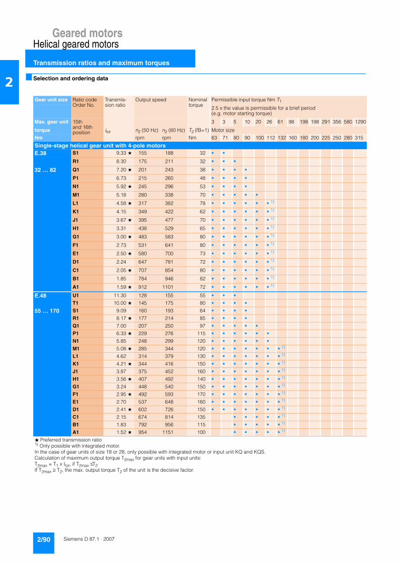
Geared motorsHelical geared motors
Transmission ratios and maximum torques
2/90 Siemens D 87.1 · 2007
2 ■ Selection and ordering data
Gear unit size Ratio code Order No.
Transmis-sion ratio
Output speed Nominal torque
Permissible input torque Nm T1
2.5 x the value is permissible for a brief period (e.g. motor starting torque)
Max. gear unit 15th and 16thposition
3 3 5 10 20 26 61 98 198 198 291 356 580 1290
torque itot n2 (50 Hz) n2 (60 Hz) T2 (fB=1) Motor size
Nm rpm rpm Nm 63 71 80 90 100 112 132 160 180 200 225 250 280 315
Single-stage helical gear unit with 4-pole motorsE.38 S1 9.33 ★ 155 188 32 • •
R1 8.30 175 211 32 • • •
32 … 82 Q1 7.20 ★ 201 243 38 • • • •
P1 6.73 215 260 48 • • • •
N1 5.92 ★ 245 296 53 • • • •
M1 5.18 280 338 70 • • • • •
L1 4.58 ★ 317 382 78 • • • • • • 1)
K1 4.15 349 422 62 • • • • • • 1)
J1 3.67 ★ 395 477 70 • • • • • • 1)
H1 3.31 438 529 65 • • • • • • 1)
G1 3.00 ★ 483 583 80 • • • • • • 1)
F1 2.73 531 641 80 • • • • • • 1)
E1 2.50 ★ 580 700 73 • • • • • • 1)
D1 2.24 647 781 72 • • • • • • 1)
C1 2.05 ★ 707 854 80 • • • • • • 1)
B1 1.85 784 946 82 • • • • • • 1)
A1 1.59 ★ 912 1101 72 • • • • • • 1)
E.48 U1 11.30 128 155 55 • • •
T1 10.00 ★ 145 175 80 • • • •
55 … 170 S1 9.09 160 193 64 • • • •
R1 8.17 ★ 177 214 85 • • • •
Q1 7.00 207 250 97 • • • • •
P1 6.33 ★ 229 276 115 • • • • • •
N1 5.85 248 299 120 • • • • • •
M1 5.08 ★ 285 344 120 • • • • • • • 1)
L1 4.62 314 379 130 • • • • • • • 1)
K1 4.21 ★ 344 416 150 • • • • • • • 1)
J1 3.87 375 452 160 • • • • • • • 1)
H1 3.56 ★ 407 492 140 • • • • • • • 1)
G1 3.24 448 540 150 • • • • • • • 1)
F1 2.95 ★ 492 593 170 • • • • • • • 1)
E1 2.70 537 648 160 • • • • • • • 1)
D1 2.41 ★ 602 726 150 • • • • • • • 1)
C1 2.15 674 814 135 • • • • • 1)
B1 1.83 792 956 115 • • • • • 1)
A1 1.52 ★ 954 1151 100 • • • • • 1)
� Preferred transmission ratio1) Only possible with integrated motor.In the case of gear units of size 18 or 28, only possible with integrated motor or input unit KQ and KQS.Calculation of maximum output torque T2max for gear units with input units:T2max = T1 x Itot, if T2max ≤ T2If T2max ≥ T2, the max. output torque T2 of the unit is the decisive factor.

Geared motorsHelical geared motors
Transmission ratios and maximum torques
2/91Siemens D 87.1 · 2007
2Selection and ordering data (continued)Gear unit size Ratio code
Order No.Transmis-sion ratio
Output speed Nominal torque
Permissible input torque Nm T1
2.5x the value is permissible for a brief period (e.g. motor starting torque)
Max. gear unit 15th and 16thposition
3 3 5 10 20 26 61 98 198 198 291 356 580 1290
torque itot n2 (50 Hz) n2 (60 Hz) T2 (fB=1) Motor size
Nm rpm rpm Nm 63 71 80 90 100 112 132 160 180 200 225 250 280 315
E68 W1 12.40 ★ 117 141 81 • • • •
V1 11.18 130 157 92 • • • •
81 … 250 U1 10.08 ★ 144 174 95 • • • •
T1 8.82 164 198 150 • • • • •
S1 7.92 ★ 183 221 170 • • • • • •
R1 7.23 201 242 150 • • • • • •
P1 6.42 ★ 226 273 170 • • • • • • •
N1 5.92 245 296 190 • • • • • • •
M1 5.36 ★ 271 326 220 • • • • • • •
L1 4.93 294 355 225 • • • • • • •
K1 4.56 ★ 318 384 220 • • • • • • • • 1)
J1 4.24 342 413 230 • • • • • • • • 1)
H1 3.74 ★ 388 468 230 • • • • • • • • 1)
G1 3.45 420 507 240 • • • • • • • • 1)
F1 3.09 ★ 469 566 250 • • • • • • • • 1)
E1 2.85 509 614 250 • • • • • • 1)
D1 2.39 607 732 230 • • • • • • 1)
C1 2.04 ★ 711 858 210 • • • • • • 1)
B1 1.70 853 1029 175 • • • • 1)
A1 1.41 ★ 1028 1241 150 • • • • 1)
E88 S1 10.33 ★ 140 169 230 • • •
R1 9.46 153 185 210 • • •
210 … 450 Q1 8.42 ★ 172 208 245 • • • •
P1 7.69 189 228 245 • • • •
N1 7.07 ★ 205 248 290 • • • •
M1 6.53 222 268 300 • • • •
L1 6.06 ★ 239 289 280 • • • • •
K1 5.65 257 310 320 • • • • •
J1 5.11 ★ 284 342 370 • • • • • • 1)
H1 4.70 309 372 385 • • • • • • 1)
G1 4.23 ★ 343 414 400 • • • • • • 1)
F1 3.90 372 449 385 • • • • • • 1)
E1 3.30 439 530 450 • • • • • • 1)
D1 2.88 ★ 503 608 435 • • • • • • 1)
C1 2.45 592 714 420 • • • • • 1)
B1 2.09 ★ 694 837 420 • • • • • 1)
A1 1.71 ★ 848 1023 355 • • • • • 1)
� Preferred transmission ratio1) Only possible with integrated motor.In the case of gear units of size 18 or 28, only possible with integrated motor or input unit KQ and KQS.Calculation of maximum output torque T2max for gear units with input units:T2max = T1 x Itot, if T2max ≤ T2If T2max ≥ T2, the max. output torque T2 of the unit is the decisive factor.
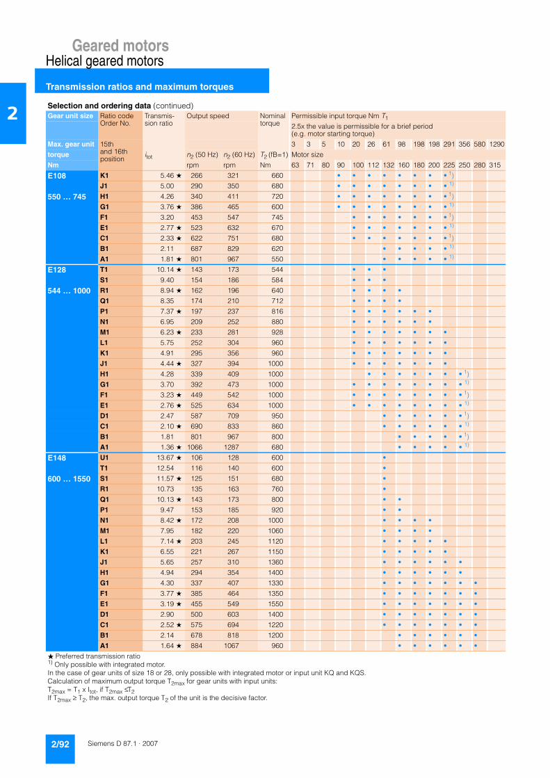
Geared motorsHelical geared motors
Transmission ratios and maximum torques
2/92 Siemens D 87.1 · 2007
2
E108 K1 5.46 ★ 266 321 660 • • • • • • • • 1)
J1 5.00 290 350 680 • • • • • • • • 1)
550 … 745 H1 4.26 340 411 720 • • • • • • • • 1)
G1 3.76 ★ 386 465 600 • • • • • • • • 1)
F1 3.20 453 547 745 • • • • • • • 1)
E1 2.77 ★ 523 632 670 • • • • • • • 1)
C1 2.33 ★ 622 751 680 • • • • • • • 1)
B1 2.11 687 829 620 • • • • • 1)
A1 1.81 ★ 801 967 550 • • • • • 1)
E128 T1 10.14 ★ 143 173 544 • • •
S1 9.40 154 186 584 • • •
544 … 1000 R1 8.94 ★ 162 196 640 • • • •
Q1 8.35 174 210 712 • • • •
P1 7.37 ★ 197 237 816 • • • • • •
N1 6.95 209 252 880 • • • • • •
M1 6.23 ★ 233 281 928 • • • • • • •
L1 5.75 252 304 960 • • • • • • •
K1 4.91 295 356 960 • • • • • • •
J1 4.44 ★ 327 394 1000 • • • • • • •
H1 4.28 339 409 1000 • • • • • • • 1)
G1 3.70 392 473 1000 • • • • • • • • 1)
F1 3.23 ★ 449 542 1000 • • • • • • • • 1)
E1 2.76 ★ 525 634 1000 • • • • • • • • 1)
D1 2.47 587 709 950 • • • • • • 1)
C1 2.10 ★ 690 833 860 • • • • • • 1)
B1 1.81 801 967 800 • • • • • 1)
A1 1.36 ★ 1066 1287 680 • • • • • 1)
E148 U1 13.67 ★ 106 128 600 •
T1 12.54 116 140 600 •
600 … 1550 S1 11.57 ★ 125 151 680 •
R1 10.73 135 163 760 •
Q1 10.13 ★ 143 173 800 • •
P1 9.47 153 185 920 • •
N1 8.42 ★ 172 208 1000 • • • •
M1 7.95 182 220 1060 • • • •
L1 7.14 ★ 203 245 1120 • • • • •
K1 6.55 221 267 1150 • • • • •
J1 5.65 257 310 1360 • • • • • •
H1 4.94 294 354 1400 • • • • • •
G1 4.30 337 407 1330 • • • • • • •
F1 3.77 ★ 385 464 1350 • • • • • • •
E1 3.19 ★ 455 549 1550 • • • • • • •
D1 2.90 500 603 1400 • • • • • • •
C1 2.52 ★ 575 694 1220 • • • • • • •
B1 2.14 678 818 1200 • • • • • •
A1 1.64 ★ 884 1067 960 • • • • • •
Selection and ordering data (continued)Gear unit size Ratio code
Order No.Transmis-sion ratio
Output speed Nominal torque
Permissible input torque Nm T1
2.5x the value is permissible for a brief period (e.g. motor starting torque)
Max. gear unit 15th and 16thposition
3 3 5 10 20 26 61 98 198 198 291 356 580 1290
torque itot n2 (50 Hz) n2 (60 Hz) T2 (fB=1) Motor size
Nm rpm rpm Nm 63 71 80 90 100 112 132 160 180 200 225 250 280 315
� Preferred transmission ratio1) Only possible with integrated motor.In the case of gear units of size 18 or 28, only possible with integrated motor or input unit KQ and KQS.Calculation of maximum output torque T2max for gear units with input units:T2max = T1 x Itot, if T2max ≤ T2If T2max ≥ T2, the max. output torque T2 of the unit is the decisive factor.
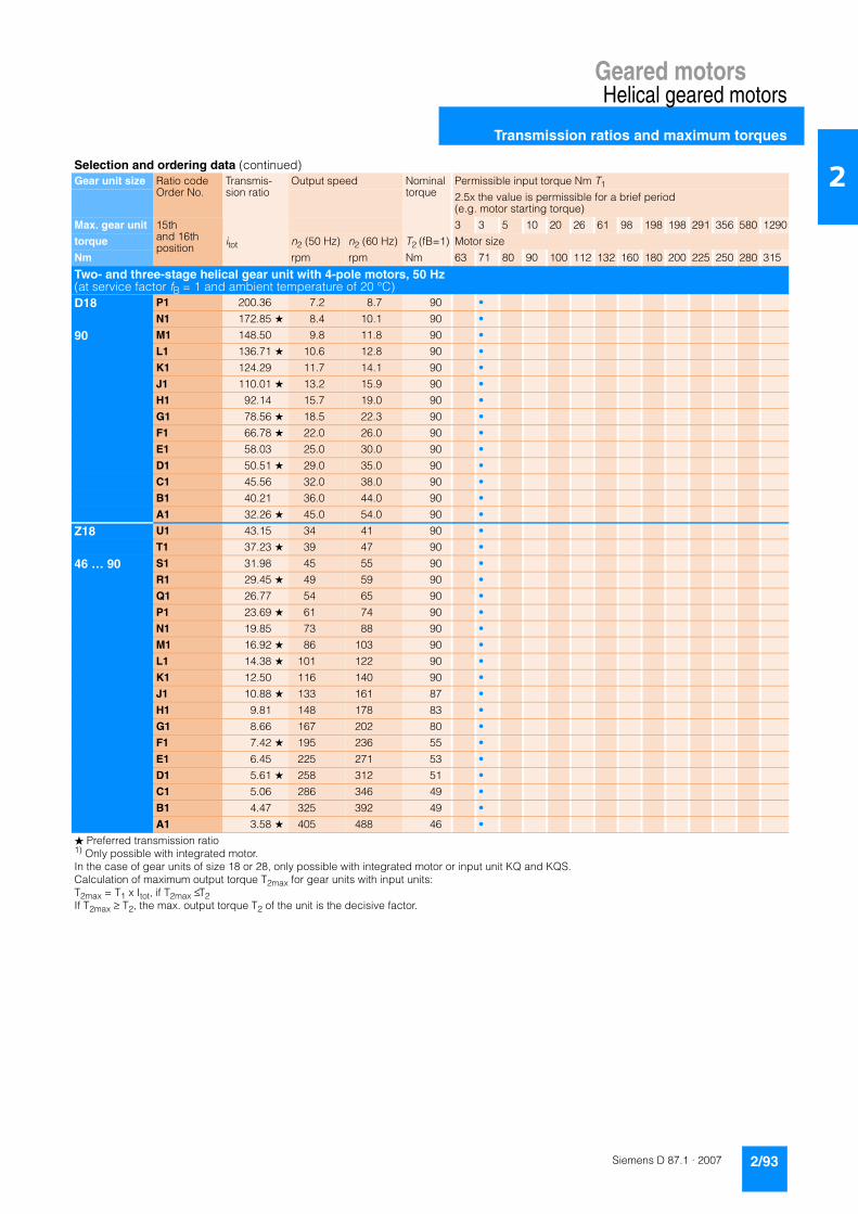
Geared motorsHelical geared motors
Transmission ratios and maximum torques
2/93Siemens D 87.1 · 2007
2
Two- and three-stage helical gear unit with 4-pole motors, 50 Hz (at service factor fB = 1 and ambient temperature of 20 °C)D18 P1 200.36 7.2 8.7 90 •
N1 172.85 ★ 8.4 10.1 90 •
90 M1 148.50 9.8 11.8 90 •
L1 136.71 ★ 10.6 12.8 90 •
K1 124.29 11.7 14.1 90 •
J1 110.01 ★ 13.2 15.9 90 •
H1 92.14 15.7 19.0 90 •
G1 78.56 ★ 18.5 22.3 90 •
F1 66.78 ★ 22.0 26.0 90 •
E1 58.03 25.0 30.0 90 •
D1 50.51 ★ 29.0 35.0 90 •
C1 45.56 32.0 38.0 90 •
B1 40.21 36.0 44.0 90 •
A1 32.26 ★ 45.0 54.0 90 •
Z18 U1 43.15 34 41 90 •
T1 37.23 ★ 39 47 90 •
46 … 90 S1 31.98 45 55 90 •
R1 29.45 ★ 49 59 90 •
Q1 26.77 54 65 90 •
P1 23.69 ★ 61 74 90 •
N1 19.85 73 88 90 •
M1 16.92 ★ 86 103 90 •
L1 14.38 ★ 101 122 90 •
K1 12.50 116 140 90 •
J1 10.88 ★ 133 161 87 •
H1 9.81 148 178 83 •
G1 8.66 167 202 80 •
F1 7.42 ★ 195 236 55 •
E1 6.45 225 271 53 •
D1 5.61 ★ 258 312 51 •
C1 5.06 286 346 49 •
B1 4.47 325 392 49 •
A1 3.58 ★ 405 488 46 •
Selection and ordering data (continued)Gear unit size Ratio code
Order No.Transmis-sion ratio
Output speed Nominal torque
Permissible input torque Nm T1
2.5x the value is permissible for a brief period (e.g. motor starting torque)
Max. gear unit 15th and 16thposition
3 3 5 10 20 26 61 98 198 198 291 356 580 1290
torque itot n2 (50 Hz) n2 (60 Hz) T2 (fB=1) Motor size
Nm rpm rpm Nm 63 71 80 90 100 112 132 160 180 200 225 250 280 315
� Preferred transmission ratio1) Only possible with integrated motor.In the case of gear units of size 18 or 28, only possible with integrated motor or input unit KQ and KQS.Calculation of maximum output torque T2max for gear units with input units:T2max = T1 x Itot, if T2max ≤ T2If T2max ≥ T2, the max. output torque T2 of the unit is the decisive factor.

Geared motorsHelical geared motors
Transmission ratios and maximum torques
2/94 Siemens D 87.1 · 2007
2
D28 N1 241.05 6.0 7.3 140 •
M1 207.96 ★ 7.0 8.4 140 • •
140 L1 178.66 8.1 9.8 140 • •
K1 164.48 ★ 8.8 10.6 140 • • •
J1 149.53 9.7 11.7 140 • • •
H1 132.35 ★ 11.0 13.2 140 • • •
G1 110.86 13.1 15.8 140 • • •
F1 94.52 ★ 15.3 18.5 140 • • •
E1 80.34 ★ 18.0 22.0 140 • • •
D1 69.82 21.0 25.0 140 • • •
C1 60.77 ★ 24.0 29.0 140 • • •
B1 54.82 26.0 32.0 140 • • •
A1 48.38 30.0 36.0 140 • • •
Z28 C2 51.35 28 34 140 •
B2 43.30 ★ 33 40 140 • •
77 … 140 A2 38.45 38 46 140 • •
X1 33.71 ★ 43 52 140 • • •
W1 30.16 48 58 140 • • •
V1 26.77 ★ 54 65 140 • • •
U1 23.46 62 75 140 • • •
T1 20.63 ★ 70 85 140 • • •
S1 18.63 78 94 140 • • • •
R1 16.24 ★ 89 108 140 • • •
Q1 14.58 99 120 140 • • •
P1 13.17 ★ 110 133 140 • • • •
N1 11.94 121 147 140 • • • •
M1 10.87 ★ 133 161 140 • • • •
L1 9.61 151 182 140 • • • •
K1 8.87 ★ 163 197 140 • • • •
J1 7.64 190 229 136 • • • •
H1 6.94 ★ 209 252 132 • • • •
G1 6.31 ★ 230 277 95 • • • •
F1 5.72 253 306 93 • • • •
E1 5.21 ★ 278 336 92 • • • •
D1 4.60 315 380 88 • • • •
C1 4.25 ★ 341 412 90 • • • •
B1 3.66 396 478 80 • • • •
A1 3.33 ★ 436 526 77 • • • •
Selection and ordering data (continued)Gear unit size Ratio code
Order No.Transmis-sion ratio
Output speed Nominal torque
Permissible input torque Nm T1
2.5x the value is permissible for a brief period (e.g. motor starting torque)
Max. gear unit 15th and 16thposition
3 3 5 10 20 26 61 98 198 198 291 356 580 1290
torque itot n2 (50 Hz) n2 (60 Hz) T2 (fB=1) Motor size
Nm rpm rpm Nm 63 71 80 90 100 112 132 160 180 200 225 250 280 315
� Preferred transmission ratio1) Only possible with integrated motor.In the case of gear units of size 18 or 28, only possible with integrated motor or input unit KQ and KQS.Calculation of maximum output torque T2max for gear units with input units:T2max = T1 x Itot, if T2max ≤ T2If T2max ≥ T2, the max. output torque T2 of the unit is the decisive factor.

Geared motorsHelical geared motors
Transmission ratios and maximum torques
2/95Siemens D 87.1 · 2007
2
Z.38-D28 M1 5905 0.24 0.29 220 •
L1 5094 ★ 0.27 0.33 220 • •
220 K1 4376 0.32 0.39 220 • •
J1 4029 ★ 0.35 0.42 220 • • •
H1 3663 0.38 0.46 220 • • •
G1 3242 ★ 0.43 0.52 220 • • •
F1 2715 0.52 0.62 220 • • •
E1 2315 ★ 0.60 0.73 220 • • •
D1 1968 ★ 0.71 0.85 220 • • •
C1 1710 0.82 0.98 220 • • •
B1 1489 ★ 0.94 1.13 220 • • •
A1 1343 1.00 1.20 220 • • •
Z38-Z28 R1 1258 1.1 1.3 220 •
Q1 1061 ★ 1.3 1.6 220 • •
220 P1 942 1.5 1.8 220 • •
N1 890 1.6 1.9 220 •
M1 751 ★ 1.9 2.2 220 • •
L1 666 2.1 2.5 220 • •
K1 584 ★ 2.4 2.9 220 • • •
J1 523 2.7 3.2 220 • • •
H1 464 ★ 3.0 3.6 220 • • •
G1 407 3.4 4.1 220 • • •
F1 358 ★ 3.9 4.7 220 • • •
E1 323 4.3 5.2 220 • • • •
D1 281 ★ 5.0 6.0 220 • • •
C1 253 5.5 6.6 220 • • •
B1 228 ★ 6.1 7.3 220 • • • •
A1 207 6.8 8.1 220 • • • •
Selection and ordering data (continued)Gear unit size Ratio code
Order No.Transmis-sion ratio
Output speed Nominal torque
Permissible input torque Nm T1
2.5x the value is permissible for a brief period (e.g. motor starting torque)
Max. gear unit 15th and 16thposition
3 3 5 10 20 26 61 98 198 198 291 356 580 1290
torque itot n2 (50 Hz) n2 (60 Hz) T2 (fB=1) Motor size
Nm rpm rpm Nm 63 71 80 90 100 112 132 160 180 200 225 250 280 315
� Preferred transmission ratio1) Only possible with integrated motor.In the case of gear units of size 18 or 28, only possible with integrated motor or input unit KQ and KQS.Calculation of maximum output torque T2max for gear units with input units:T2max = T1 x Itot, if T2max ≤ T2If T2max ≥ T2, the max. output torque T2 of the unit is the decisive factor.

Geared motorsHelical geared motors
Transmission ratios and maximum torques
2/96 Siemens D 87.1 · 2007
2
D38 S1 191.75 ★ 7.6 9.1 220 • • •
R1 170.24 8.5 10.3 220 • • •
220 Q1 149.26 ★ 9.7 11.7 220 • • • •
P1 133.57 10.9 13.1 220 • • • •
N1 118.55 ★ 12.2 14.8 220 • • • •
M1 103.89 14.0 16.8 220 • • • •
L1 91.34 ★ 15.9 19.2 220 • • • •
K1 82.52 17.6 21.0 220 • • • •
J1 71.91 ★ 20.0 24.0 220 • • • •
H1 64.58 22.0 27.0 220 • • • •
G1 58.30 ★ 25.0 30.0 220 • • • •
F1 52.86 27.0 33.0 220 • • • •
E1 48.10 ★ 30.0 36.0 220 • • • •
D1 42.53 34.0 41.0 220 • • • •
C1 39.28 ★ 37.0 45.0 220 • • • •
B1 33.82 43.0 52.0 220 • • • •
A1 30.74 ★ 47.0 57.0 220 • • • •
Z38 A2 44.12 ★ 33 40 220 • • •
X1 39.24 37 45 208 • • •
160 … 220 W1 34.04 ★ 43 51 220 • • • •
V1 31.80 46 55 220 • • • •
U1 27.97 ★ 52 63 220 • • • •
T1 24.50 59 71 220 • • • • •
S1 21.67 ★ 67 81 220 • • • • • • 1)
R1 19.64 74 89 220 • • • • • • 1)
Q1 17.33 ★ 84 101 220 • • • • • • 1)
P1 15.64 93 112 220 • • • • • • 1)
N1 14.18 ★ 102 123 220 • • • • • • 1)
M1 12.92 112 135 220 • • • • • • 1)
L1 11.82 ★ 123 148 220 • • • • • • 1)
K1 10.57 137 166 210 • • • • • • 1)
J1 9.70 ★ 149 180 200 • • • • • • 1)
H1 8.75 166 200 195 • • • • • • 1)
G1 7.52 ★ 193 233 190 • • • • • • 1)
F1 7.50 ★ 193 233 185 • • • • • • 1)
D1 6.71 216 261 180 • • • • • • 1)
C1 6.16 ★ 235 284 170 • • • • • • 1)
B1 5.55 261 315 165 • • • • • • 1)
A1 4.77 ★ 304 367 160 • • • • • • 1)
Selection and ordering data (continued)Gear unit size Ratio code
Order No.Transmis-sion ratio
Output speed Nominal torque
Permissible input torque Nm T1
2.5x the value is permissible for a brief period (e.g. motor starting torque)
Max. gear unit 15th and 16thposition
3 3 5 10 20 26 61 98 198 198 291 356 580 1290
torque itot n2 (50 Hz) n2 (60 Hz) T2 (fB=1) Motor size
Nm rpm rpm Nm 63 71 80 90 100 112 132 160 180 200 225 250 280 315
� Preferred transmission ratio1) Only possible with integrated motor.In the case of gear units of size 18 or 28, only possible with integrated motor or input unit KQ and KQS.Calculation of maximum output torque T2max for gear units with input units:T2max = T1 x Itot, if T2max ≤ T2If T2max ≥ T2, the max. output torque T2 of the unit is the decisive factor.

Geared motorsHelical geared motors
Transmission ratios and maximum torques
2/97Siemens D 87.1 · 2007
2
D48-D28 N1 27940 0.05 0.06 450 •
M1 24104 ★ 0.06 0.07 450 • •
450 L1 20708 0.07 0.08 450 • •
K1 19065 ★ 0.07 0.08 450 • • •
J1 17332 0.08 0.10 450 • • •
H1 15341 ★ 0.09 0.11 450 • • •
G1 12849 0.11 0.13 450 • • •
F1 10956 ★ 0.13 0.15 450 • • •
E1 9312 ★ 0.15 0.18 450 • • •
D1 8093 0.17 0.21 450 • • •
C1 7044 ★ 0.20 0.24 450 • • •
B1 6354 0.22 0.26 450 • • •
A1 5608 0.25 0.30 450 • • •
D48-Z28 H2 5019 ★ 0.28 0.34 450 • •
G2 4456 0.31 0.38 450 • •
450 F2 3907 ★ 0.36 0.43 450 • • •
E2 3496 0.40 0.48 450 • • •
D2 3103 ★ 0.45 0.54 450 • • •
C2 2720 0.51 0.62 450 • • •
B2 2391 ★ 0.59 0.70 450 • • •
A2 2160 0.65 0.78 450 • • • •
X1 1882 ★ 0.74 0.89 450 • • •
W1 1690 0.83 0.99 450 • • •
V1 1526 ★ 0.92 1.10 450 • • • •
U1 1384 1.00 1.20 450 • • • •
T1 1259 ★ 1.10 1.30 450 • • • •
S1 1113 1.30 1.50 450 • • • •
R1 1028 ★ 1.40 1.60 450 • • • •
Q1 885 1.60 1.90 450 • • • •
P1 805 ★ 1.70 2.10 450 • • • •
N1 731 ★ 1.90 2.30 450 • • • •
M1 663 2.10 2.50 450 • • • •
L1 603 ★ 2.30 2.80 450 • • • •
K1 534 2.60 3.10 450 • • • •
J1 493 ★ 2.80 3.40 450 • • • •
H1 424 3.30 3.90 450 • • • •
G1 423 ★ 3.30 4.00 450 • • • •
F1 384 3.70 4.40 450 • • • •
E1 349 ★ 4.00 4.80 450 • • • •
D1 309 4.50 5.40 450 • • • •
C1 285 ★ 4.90 5.90 450 • • • •
B1 246 5.70 6.80 450 • • • •
A1 223 ★ 6.30 7.50 450 • • • •
Selection and ordering data (continued)Gear unit size Ratio code
Order No.Transmis-sion ratio
Output speed Nominal torque
Permissible input torque Nm T1
2.5x the value is permissible for a brief period (e.g. motor starting torque)
Max. gear unit 15th and 16thposition
3 3 5 10 20 26 61 98 198 198 291 356 580 1290
torque itot n2 (50 Hz) n2 (60 Hz) T2 (fB=1) Motor size
Nm rpm rpm Nm 63 71 80 90 100 112 132 160 180 200 225 250 280 315
� Preferred transmission ratio1) Only possible with integrated motor.In the case of gear units of size 18 or 28, only possible with integrated motor or input unit KQ and KQS.Calculation of maximum output torque T2max for gear units with input units:T2max = T1 x Itot, if T2max ≤ T2If T2max ≥ T2, the max. output torque T2 of the unit is the decisive factor.
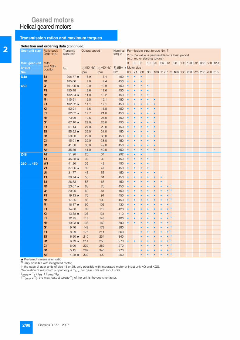
Geared motorsHelical geared motors
Transmission ratios and maximum torques
2/98 Siemens D 87.1 · 2007
2
D48 S1 208.77 ★ 6.9 8.4 450 • • •
R1 185.66 7.8 9.4 450 • • •
450 Q1 161.05 ★ 9.0 10.9 450 • • • •
P1 150.48 9.6 11.6 450 • • • •
N1 132.34 ★ 11.0 13.2 450 • • • •
M1 115.91 12.5 15.1 450 • • • • •
L1 102.52 ★ 14.1 17.1 450 • • • • •
K1 92.91 15.6 18.8 450 • • • • •
J1 82.02 ★ 17.7 21.0 450 • • • • •
H1 73.99 19.6 24.0 450 • • • • •
G1 67.10 ★ 22.0 26.0 450 • • • • •
F1 61.14 24.0 29.0 450 • • • • •
E1 55.92 ★ 26.0 31.0 450 • • • • •
D1 50.00 29.0 35.0 450 • • • • •
C1 45.91 ★ 32.0 38.0 450 • • • • •
B1 41.38 35.0 42.0 450 • • • • •
A1 35.59 41.0 49.0 450 • • • • •
Z48 A2 51.28 28 34 292 • • •
X1 45.38 ★ 32 39 450 • • • •
260 … 450 W1 41.26 35 42 450 • • • •
V1 37.06 ★ 39 47 450 • • • •
U1 31.77 46 55 450 • • • • •
T1 28.74 ★ 50 61 450 • • • • • •
S1 26.53 55 66 450 • • • • • •
R1 23.07 ★ 63 76 450 • • • • • • • 1)
Q1 20.95 69 84 450 • • • • • • • 1)
P1 19.13 ★ 76 91 450 • • • • • • • 1)
N1 17.55 83 100 450 • • • • • • • 1)
M1 16.17 ★ 90 108 430 • • • • • • • 1)
L1 14.68 99 119 420 • • • • • • • 1)
K1 13.38 ★ 108 131 410 • • • • • • • 1)
J1 12.25 118 143 400 • • • • • • • 1)
H1 10.93 ★ 133 160 390 • • • • • • • 1)
G1 9.76 149 179 380 • • • • • 1)
F1 8.29 175 211 360 • • • • • 1)
E1 6.90 ★ 210 254 340 • • • • • 1)
D1 6.79 ★ 214 258 270 • • • • • • • 1)
C1 6.06 239 289 270 • • • • • 1)
B1 5.15 282 340 270 • • • • • 1)
A1 4.28 ★ 339 409 260 • • • • • 1)
Selection and ordering data (continued)Gear unit size Ratio code
Order No.Transmis-sion ratio
Output speed Nominal torque
Permissible input torque Nm T1
2.5x the value is permissible for a brief period (e.g. motor starting torque)
Max. gear unit 15th and 16thposition
3 3 5 10 20 26 61 98 198 198 291 356 580 1290
torque itot n2 (50 Hz) n2 (60 Hz) T2 (fB=1) Motor size
Nm rpm rpm Nm 63 71 80 90 100 112 132 160 180 200 225 250 280 315
� Preferred transmission ratio1) Only possible with integrated motor.In the case of gear units of size 18 or 28, only possible with integrated motor or input unit KQ and KQS.Calculation of maximum output torque T2max for gear units with input units:T2max = T1 x Itot, if T2max ≤ T2If T2max ≥ T2, the max. output torque T2 of the unit is the decisive factor.

Geared motorsHelical geared motors
Transmission ratios and maximum torques
2/99Siemens D 87.1 · 2007
2
D68-D28 N1 41961 0.03 0.04 800 •
M1 36200 ★ 0.04 0.05 800 • •
800 L1 31101 0.05 0.05 800 • •
K1 28633 ★ 0.05 0.06 800 • • •
J1 26030 0.05 0.07 800 • • •
H1 23039 ★ 0.06 0.07 800 • • •
G1 19297 0.07 0.09 800 • • •
F1 16454 ★ 0.09 0.10 800 • • •
E1 13986 ★ 0.10 0.12 800 • • •
D1 12154 0.12 0.14 800 • • •
C1 10579 ★ 0.13 0.16 800 • • •
B1 9543 0.15 0.18 800 • • •
A1 8422 0.17 0.20 800 • • •
D68-Z28 H2 7538 ★ 0.19 0.22 800 • •
G2 6693 0.21 0.25 800 • •
800 F2 5868 ★ 0.24 0.29 800 • • •
E2 5251 0.27 0.32 800 • • •
D2 4660 ★ 0.30 0.36 800 • • •
C2 4084 0.34 0.41 800 • • •
B2 3591 ★ 0.39 0.47 800 • • •
A2 3244 0.43 0.52 800 • • • •
X1 2827 ★ 0.50 0.59 800 • • •
W1 2539 0.55 0.66 800 • • •
V1 2292 ★ 0.61 0.73 800 • • • •
U1 2078 0.67 0.81 800 • • • •
T1 1891 ★ 0.74 0.89 800 • • • •
S1 1672 0.84 1.00 800 • • • •
R1 1544 ★ 0.91 1.10 800 • • • •
Q1 1329 1.10 1.30 800 • • • •
P1 1208 ★ 1.20 1.40 800 • • • •
N1 1098 ★ 1.30 1.50 800 • • • •
M1 996 1.40 1.70 800 • • • •
L1 906 ★ 1.50 1.90 800 • • • •
K1 801 1.80 2.10 800 • • • •
J1 740 ★ 1.90 2.30 800 • • • •
H1 637 2.20 2.60 800 • • • •
G1 607 ★ 2.30 2.80 800 • • • •
F1 550 2.50 3.10 800 • • • •
E1 501 ★ 2.80 3.40 800 • • • •
D1 443 3.20 3.80 800 • • • •
C1 409 ★ 3.40 4.10 800 • • • •
B1 352 4.00 4.80 800 • • • •
A1 320 ★ 4.40 5.30 800 • • • •
Selection and ordering data (continued)Gear unit size Ratio code
Order No.Transmis-sion ratio
Output speed Nominal torque
Permissible input torque Nm T1
2.5x the value is permissible for a brief period (e.g. motor starting torque)
Max. gear unit 15th and 16thposition
3 3 5 10 20 26 61 98 198 198 291 356 580 1290
torque itot n2 (50 Hz) n2 (60 Hz) T2 (fB=1) Motor size
Nm rpm rpm Nm 63 71 80 90 100 112 132 160 180 200 225 250 280 315
� Preferred transmission ratio1) Only possible with integrated motor.In the case of gear units of size 18 or 28, only possible with integrated motor or input unit KQ and KQS.Calculation of maximum output torque T2max for gear units with input units:T2max = T1 x Itot, if T2max ≤ T2If T2max ≥ T2, the max. output torque T2 of the unit is the decisive factor.
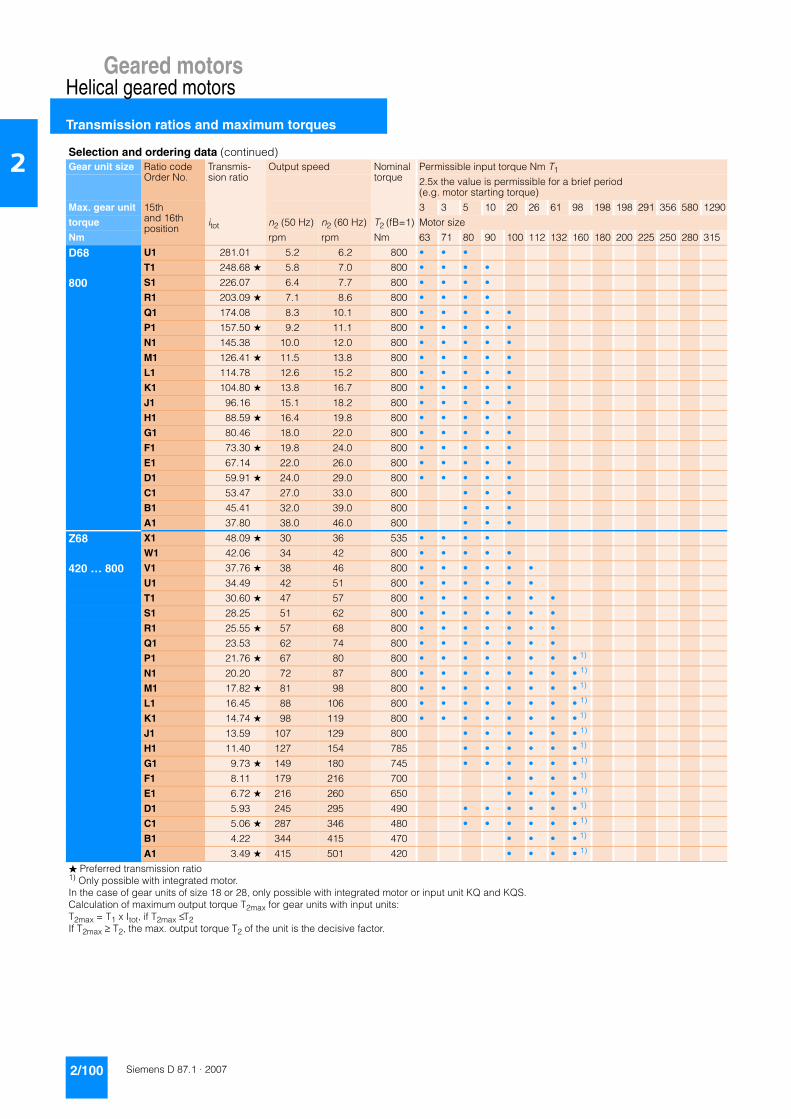
Geared motorsHelical geared motors
Transmission ratios and maximum torques
2/100 Siemens D 87.1 · 2007
2
D68 U1 281.01 5.2 6.2 800 • • •
T1 248.68 ★ 5.8 7.0 800 • • • •
800 S1 226.07 6.4 7.7 800 • • • •
R1 203.09 ★ 7.1 8.6 800 • • • •
Q1 174.08 8.3 10.1 800 • • • • •
P1 157.50 ★ 9.2 11.1 800 • • • • •
N1 145.38 10.0 12.0 800 • • • • •
M1 126.41 ★ 11.5 13.8 800 • • • • •
L1 114.78 12.6 15.2 800 • • • • •
K1 104.80 ★ 13.8 16.7 800 • • • • •
J1 96.16 15.1 18.2 800 • • • • •
H1 88.59 ★ 16.4 19.8 800 • • • • •
G1 80.46 18.0 22.0 800 • • • • •
F1 73.30 ★ 19.8 24.0 800 • • • • •
E1 67.14 22.0 26.0 800 • • • • •
D1 59.91 ★ 24.0 29.0 800 • • • • •
C1 53.47 27.0 33.0 800 • • •
B1 45.41 32.0 39.0 800 • • •
A1 37.80 38.0 46.0 800 • • •
Z68 X1 48.09 ★ 30 36 535 • • • •
W1 42.06 34 42 800 • • • • •
420 … 800 V1 37.76 ★ 38 46 800 • • • • • •
U1 34.49 42 51 800 • • • • • •
T1 30.60 ★ 47 57 800 • • • • • • •
S1 28.25 51 62 800 • • • • • • •
R1 25.55 ★ 57 68 800 • • • • • • •
Q1 23.53 62 74 800 • • • • • • •
P1 21.76 ★ 67 80 800 • • • • • • • • 1)
N1 20.20 72 87 800 • • • • • • • • 1)
M1 17.82 ★ 81 98 800 • • • • • • • • 1)
L1 16.45 88 106 800 • • • • • • • • 1)
K1 14.74 ★ 98 119 800 • • • • • • • • 1)
J1 13.59 107 129 800 • • • • • • 1)
H1 11.40 127 154 785 • • • • • • 1)
G1 9.73 ★ 149 180 745 • • • • • • 1)
F1 8.11 179 216 700 • • • • 1)
E1 6.72 ★ 216 260 650 • • • • 1)
D1 5.93 245 295 490 • • • • • • 1)
C1 5.06 ★ 287 346 480 • • • • • • 1)
B1 4.22 344 415 470 • • • • 1)
A1 3.49 ★ 415 501 420 • • • • 1)
Selection and ordering data (continued)Gear unit size Ratio code
Order No.Transmis-sion ratio
Output speed Nominal torque
Permissible input torque Nm T1
2.5x the value is permissible for a brief period (e.g. motor starting torque)
Max. gear unit 15th and 16thposition
3 3 5 10 20 26 61 98 198 198 291 356 580 1290
torque itot n2 (50 Hz) n2 (60 Hz) T2 (fB=1) Motor size
Nm rpm rpm Nm 63 71 80 90 100 112 132 160 180 200 225 250 280 315
� Preferred transmission ratio1) Only possible with integrated motor.In the case of gear units of size 18 or 28, only possible with integrated motor or input unit KQ and KQS.Calculation of maximum output torque T2max for gear units with input units:T2max = T1 x Itot, if T2max ≤ T2If T2max ≥ T2, the max. output torque T2 of the unit is the decisive factor.

Geared motorsHelical geared motors
Transmission ratios and maximum torques
2/101Siemens D 87.1 · 2007
2
D.88-D.28 N1 46233 0.03 0.04 1680 •
M1 39885 ★ 0.04 0.04 1680 • •
800 L1 34267 0.04 0.05 1680 • •
K1 31547 ★ 0.04 0.05 1680 • • •
J1 28679 0.05 0.06 1680 • • •
H1 25384 ★ 0.06 0.07 1680 • • •
G1 21262 0.07 0.08 1680 • • •
F1 18129 ★ 0.08 0.09 1680 • • •
E1 15409 ★ 0.09 0.11 1680 • • •
D1 13391 0.10 0.13 1680 • • •
C1 11656 ★ 0.12 0.14 1680 • • •
B1 10514 0.13 0.16 1680 • • •
A1 9279 0.15 0.18 1680 • • •
D.88-Z.28 H2 8305 ★ 0.17 0.20 1680 • •
G2 7374 0.19 0.23 1680 • •
800 F2 6465 ★ 0.22 0.26 1680 • • •
E2 5785 0.24 0.29 1680 • • •
D2 5134 ★ 0.27 0.33 1680 • • •
C2 4500 0.31 0.37 1680 • • •
B2 3957 ★ 0.35 0.43 1680 • • •
A2 3574 0.39 0.47 1680 • • • •
X1 3114 ★ 0.45 0.54 1680 • • •
W1 2797 0.50 0.60 1680 • • •
V1 2525 ★ 0.55 0.67 1680 • • • •
U1 2290 0.61 0.73 1680 • • • •
T1 2084 ★ 0.67 0.81 1680 • • • •
S1 1842 0.76 0.91 1680 • • • •
R1 1701 ★ 0.82 0.99 1680 • • • •
Q1 1465 0.96 1.10 1680 • • • •
P1 1331 ★ 1.10 1.30 1680 • • • •
N1 1210 ★ 1.20 1.40 1680 • • • •
M1 1097 1.30 1.50 1680 • • • •
L1 999 ★ 1.40 1.70 1680 • • • •
K1 883 1.60 1.90 1680 • • • •
J1 815 ★ 1.70 2.10 1680 • • • •
H1 702 2.00 2.40 1680 • • • •
G1 647 ★ 2.20 2.60 1680 • • • •
F1 587 2.40 2.90 1680 • • • •
E1 534 ★ 2.60 3.10 1680 • • • •
D1 472 3.00 3.60 1680 • • • •
C1 436 ★ 3.20 3.90 1680 • • • •
B1 375 3.70 4.50 1680 • • • •
A1 341 ★ 4.10 4.90 1680 • • • •
Selection and ordering data (continued)Gear unit size Ratio code
Order No.Transmis-sion ratio
Output speed Nominal torque
Permissible input torque Nm T1
2.5x the value is permissible for a brief period (e.g. motor starting torque)
Max. gear unit 15th and 16thposition
3 3 5 10 20 26 61 98 198 198 291 356 580 1290
torque itot n2 (50 Hz) n2 (60 Hz) T2 (fB=1) Motor size
Nm rpm rpm Nm 63 71 80 90 100 112 132 160 180 200 225 250 280 315
� Preferred transmission ratio1) Only possible with integrated motor.In the case of gear units of size 18 or 28, only possible with integrated motor or input unit KQ and KQS.Calculation of maximum output torque T2max for gear units with input units:T2max = T1 x Itot, if T2max ≤ T2If T2max ≥ T2, the max. output torque T2 of the unit is the decisive factor.
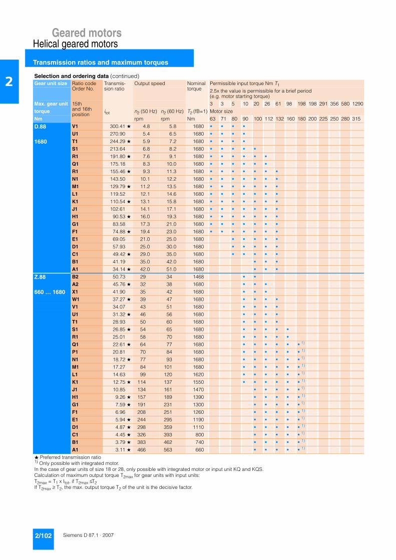
Geared motorsHelical geared motors
Transmission ratios and maximum torques
2/102 Siemens D 87.1 · 2007
2
D.88 V1 300.41 ★ 4.8 5.8 1680 • • • •
U1 270.90 5.4 6.5 1680 • • • •
1680 T1 244.29 ★ 5.9 7.2 1680 • • • •
S1 213.64 6.8 8.2 1680 • • • • •
R1 191.80 ★ 7.6 9.1 1680 • • • • • •
Q1 175.18 8.3 10.0 1680 • • • • • •
R1 155.46 ★ 9.3 11.3 1680 • • • • • • •
N1 143.50 10.1 12.2 1680 • • • • • • •
M1 129.79 ★ 11.2 13.5 1680 • • • • • • •
L1 119.52 12.1 14.6 1680 • • • • • • •
K1 110.54 ★ 13.1 15.8 1680 • • • • • • •
J1 102.61 14.1 17.1 1680 • • • • • • •
H1 90.53 ★ 16.0 19.3 1680 • • • • • • •
G1 83.58 17.3 21.0 1680 • • • • • • •
F1 74.88 ★ 19.4 23.0 1680 • • • • • • •
E1 69.05 21.0 25.0 1680 • • • • •
D1 57.93 25.0 30.0 1680 • • • • •
C1 49.42 ★ 29.0 35.0 1680 • • • • •
B1 41.19 35.0 42.0 1680 • • •
A1 34.14 ★ 42.0 51.0 1680 • • •
Z.88 B2 50.73 29 34 1468 • •
A2 45.76 ★ 32 38 1680 • • •
660 … 1680 X1 41.90 35 42 1680 • • •
W1 37.27 ★ 39 47 1680 • • • •
V1 34.07 43 51 1680 • • • •
U1 31.32 ★ 46 56 1680 • • • •
T1 28.93 50 60 1680 • • • •
S1 26.85 ★ 54 65 1680 • • • • •
R1 25.01 58 70 1680 • • • • •
Q1 22.61 ★ 64 77 1680 • • • • • • 1)
P1 20.81 70 84 1680 • • • • • • 1)
N1 18.72 ★ 77 93 1680 • • • • • • 1)
M1 17.27 84 101 1680 • • • • • • 1)
L1 14.63 99 120 1620 • • • • • • 1)
K1 12.75 ★ 114 137 1550 • • • • • • 1)
J1 10.85 134 161 1470 • • • • • 1)
H1 9.26 ★ 157 189 1390 • • • • • 1)
G1 7.59 ★ 191 231 1300 • • • • • 1)
F1 6.96 208 251 1260 • • • • • 1)
E1 5.94 ★ 244 295 1190 • • • • • 1)
D1 4.87 ★ 298 359 1110 • • • • • 1)
C1 4.45 ★ 326 393 800 • • • • • 1)
B1 3.79 ★ 383 462 740 • • • • • 1)
A1 3.11 ★ 466 563 660 • • • • • 1)
Selection and ordering data (continued)Gear unit size Ratio code
Order No.Transmis-sion ratio
Output speed Nominal torque
Permissible input torque Nm T1
2.5x the value is permissible for a brief period (e.g. motor starting torque)
Max. gear unit 15th and 16thposition
3 3 5 10 20 26 61 98 198 198 291 356 580 1290
torque itot n2 (50 Hz) n2 (60 Hz) T2 (fB=1) Motor size
Nm rpm rpm Nm 63 71 80 90 100 112 132 160 180 200 225 250 280 315
� Preferred transmission ratio1) Only possible with integrated motor.In the case of gear units of size 18 or 28, only possible with integrated motor or input unit KQ and KQS.Calculation of maximum output torque T2max for gear units with input units:T2max = T1 x Itot, if T2max ≤ T2If T2max ≥ T2, the max. output torque T2 of the unit is the decisive factor.
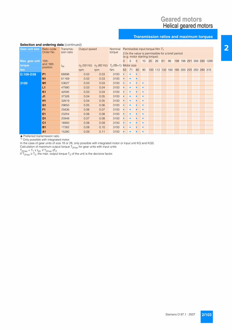
Geared motorsHelical geared motors
Transmission ratios and maximum torques
2/103Siemens D 87.1 · 2007
2
D.108-D38 P1 68896 0.02 0.03 3100 • • •
N1 61169 0.02 0.03 3100 • • •
3100 M1 53627 0.03 0.03 3100 • • • •
L1 47990 0.03 0.04 3100 • • • •
K1 42595 0.03 0.04 3100 • • • •
J1 37326 0.04 0.05 3100 • • • •
H1 32819 0.04 0.05 3100 • • • •
G1 29650 0.05 0.06 3100 • • • •
F1 25836 0.06 0.07 3100 • • • •
E1 23204 0.06 0.08 3100 • • • •
D1 20948 0.07 0.08 3100 • • • •
C1 18993 0.08 0.09 3100 • • • •
B1 17282 0.08 0.10 3100 • • • •
A1 15280 0.09 0.11 3100 • • • •
Selection and ordering data (continued)Gear unit size Ratio code
Order No.Transmis-sion ratio
Output speed Nominal torque
Permissible input torque Nm T1
2.5x the value is permissible for a brief period (e.g. motor starting torque)
Max. gear unit 15th and 16thposition
3 3 5 10 20 26 61 98 198 198 291 356 580 1290
torque itot n2 (50 Hz) n2 (60 Hz) T2 (fB=1) Motor size
Nm rpm rpm Nm 63 71 80 90 100 112 132 160 180 200 225 250 280 315
� Preferred transmission ratio1) Only possible with integrated motor.In the case of gear units of size 18 or 28, only possible with integrated motor or input unit KQ and KQS.Calculation of maximum output torque T2max for gear units with input units:T2max = T1 x Itot, if T2max ≤ T2If T2max ≥ T2, the max. output torque T2 of the unit is the decisive factor.

Geared motorsHelical geared motors
Transmission ratios and maximum torques
2/104 Siemens D 87.1 · 2007
2
D.108-Z38 P2 15853 0.09 0.11 3100 • • •
N2 14098 0.10 0.12 3100 • • •
3100 M2 12229 0.12 0.14 3100 • • • •
L2 11426 0.13 0.15 3100 • • • •
K2 10049 0.14 0.17 3100 • • • •
J2 8801 0.16 0.20 3100 • • • • •
H2 7785 0.19 0.22 3100 • • • • •
G2 7055 0.21 0.25 3100 • • • • •
F2 6228 0.23 0.28 3100 • • • • •
E2 5618 0.26 0.31 3100 • • • • •
D2 5096 0.28 0.34 3100 • • • • •
C2 4643 0.31 0.38 3100 • • • • •
B2 4246 0.34 0.41 3100 • • • • •
A2 3797 0.38 0.46 3100 • • • • •
X1 3624 0.40 0.48 3100 • • •
W1 3223 0.45 0.54 3100 • • •
V1 2796 0.52 0.63 3100 • • • •
U1 2612 0.56 0.67 3100 • • • •
T1 2297 0.63 0.76 3100 • • • •
S1 2012 0.72 0.87 3100 • • • • •
R1 1780 0.81 0.98 3100 • • • • •
Q1 1613 0.90 1.10 3100 • • • • •
P1 1424 1.00 1.20 3100 • • • • •
N1 1284 1.10 1.40 3100 • • • • •
M1 1165 1.20 1.50 3100 • • • • •
L1 1061 1.40 1.60 3100 • • • • •
K1 971 1.50 1.80 3100 • • • • •
J1 868 1.70 2.00 3100 • • • • •
H1 797 1.80 2.20 3100 • • • • •
G1 718 2.00 2.40 3100 • • • • •
F1 618 2.30 2.80 3100 • • • • •
E1 616 2.40 2.80 3100 • • • • •
D1 551 2.60 3.20 3100 • • • • •
C1 506 2.90 3.50 3100 • • • • •
B1 456 3.20 3.80 3100 • • • • •
A1 392 3.70 4.50 3100 • • • • •
Selection and ordering data (continued)Gear unit size Ratio code
Order No.Transmis-sion ratio
Output speed Nominal torque
Permissible input torque Nm T1
2.5x the value is permissible for a brief period (e.g. motor starting torque)
Max. gear unit 15th and 16thposition
3 3 5 10 20 26 61 98 198 198 291 356 580 1290
torque itot n2 (50 Hz) n2 (60 Hz) T2 (fB=1) Motor size
Nm rpm rpm Nm 63 71 80 90 100 112 132 160 180 200 225 250 280 315
� Preferred transmission ratio1) Only possible with integrated motor.In the case of gear units of size 18 or 28, only possible with integrated motor or input unit KQ and KQS.Calculation of maximum output torque T2max for gear units with input units:T2max = T1 x Itot, if T2max ≤ T2If T2max ≥ T2, the max. output torque T2 of the unit is the decisive factor.

Geared motorsHelical geared motors
Transmission ratios and maximum torques
2/105Siemens D 87.1 · 2007
2
D.108 V1 359.30 4.0 4.9 3100 • •
K1 325.21 ★ 4.5 5.4 3100 • •
3100 T1 284.73 5.1 6.1 3100 • • •
S1 256.86 ★ 5.6 6.8 3100 • • • •
R1 235.19 6.2 7.4 3100 • • • •
Q1 209.21 ★ 6.9 8.4 3100 • • • • •
P1 191.21 7.6 9.2 3100 • • • • •
N1 175.78 ★ 8.2 10.0 3100 • • • • •
M1 162.40 8.9 10.8 3100 • • • • •
L1 150.70 ★ 9.6 11.6 3100 • • • • • •
K1 140.37 10.3 12.5 3100 • • • • • •
J1 126.90 ★ 11.4 13.8 3100 • • • • • •
H1 116.83 12.4 15.0 3100 • • • • • •
G1 105.08 ★ 13.8 16.7 3100 • • • • • •
F1 96.94 15.0 18.1 3100 • • • • • •
E1 82.14 17.7 21.0 3100 • • • • • •
D1 71.59 ★ 20.0 24.0 3100 • • • • • •
C1 60.90 24.0 29.0 3100 • • • •
B1 51.97 ★ 28.0 34.0 3100 • • • •
A1 42.61 ★ 34.0 41.0 3100 • • • •
Z.108 E2 59.05 ★ 25 30 2368 • • •
D2 54.15 27 32 2306 • • •
1080 … 3100 C2 48.38 ★ 30 36 3100 • • • •
B2 44.31 33 39 3100 • • • •
A2 40.82 ★ 36 43 3100 • • • •
X1 37.79 38 46 3100 • • • •
W1 35.14 ★ 41 50 3100 • • • • •
V1 32.81 44 53 3100 • • • • •
U1 29.35 ★ 49 60 3100 • • • • • • •
T1 27.20 53 64 3100 • • • • • • •
S1 24.94 ★ 58 70 3100 • • • • • • • • 1)
R1 22.86 63 77 3100 • • • • • • • • 1)
Q1 19.48 74 90 3100 • • • • • • • • 1)
P1 17.19 ★ 84 102 3100 • • • • • • • • 1)
N1 14.63 99 120 3100 • • • • • • • 1)
M1 12.68 ★ 114 138 3100 • • • • • • • 1)
L1 10.67 ★ 136 164 3100 • • • • • • • 1)
K1 9.62 151 182 3100 • • • • • 1)
J1 8.27 ★ 175 212 3100 • • • • • 1)
H1 7.10 ★ 204 246 1800 • • • • • • • 1)
G1 6.41 226 273 1760 • • • • • 1)
E1 5.51 ★ 263 318 1700 • • • • • 1)
D1 5.24 ★ 277 334 1140 • • • • • 1)
C1 4.41 ★ 329 397 1140 • • • • • 1)
B1 3.98 ★ 364 440 1120 • • • • • 1)
A1 3.42 ★ 424 512 1080 • • • • • 1)
Selection and ordering data (continued)Gear unit size Ratio code
Order No.Transmis-sion ratio
Output speed Nominal torque
Permissible input torque Nm T1
2.5x the value is permissible for a brief period (e.g. motor starting torque)
Max. gear unit 15th and 16thposition
3 3 5 10 20 26 61 98 198 198 291 356 580 1290
torque itot n2 (50 Hz) n2 (60 Hz) T2 (fB=1) Motor size
Nm rpm rpm Nm 63 71 80 90 100 112 132 160 180 200 225 250 280 315
� Preferred transmission ratio1) Only possible with integrated motor.In the case of gear units of size 18 or 28, only possible with integrated motor or input unit KQ and KQS.Calculation of maximum output torque T2max for gear units with input units:T2max = T1 x Itot, if T2max ≤ T2If T2max ≥ T2, the max. output torque T2 of the unit is the decisive factor.

Geared motorsHelical geared motors
Transmission ratios and maximum torques
2/106 Siemens D 87.1 · 2007
2
D.128-D38 P1 51420 ★ 0.03 0.03 5100 • • •
N1 45652 0.03 0.04 5100 • • •
5100 M1 40024 ★ 0.04 0.04 5100 • • • •
L1 35817 0.04 0.05 5100 • • • •
K1 31790 ★ 0.05 0.06 5100 • • • •
J1 27858 0.05 0.06 5100 • • • •
H1 24494 ★ 0.06 0.07 5100 • • • •
G1 22129 0.07 0.08 5100 • • • •
F1 19282 ★ 0.08 0.09 5100 • • • •
E1 17318 0.08 0.10 5100 • • • •
D1 15634 ★ 0.09 0.11 5100 • • • •
C1 14175 0.10 0.12 5100 • • • •
B1 12898 ★ 0.11 0.14 5100 • • • •
A1 11404 0.13 0.15 5100 • • • •
D.128-Z38 X1 11831 ★ 0.12 0.15 5100 • • •
W1 10521 0.14 0.17 5100 • • •
5100 V1 9127 ★ 0.16 0.19 5100 • • • •
U1 8528 0.17 0.21 5100 • • • •
T1 7500 ★ 0.19 0.23 5100 • • • •
S1 6569 0.22 0.27 5100 • • • • •
R1 5810 ★ 0.25 0.30 5100 • • • • •
Q1 5266 0.28 0.33 5100 • • • • •
P1 4648 ★ 0.31 0.38 5100 • • • • •
N1 4193 0.35 0.42 5100 • • • • •
M1 3803 ★ 0.38 0.46 5100 • • • • •
L1 3465 0.42 0.51 5100 • • • • •
K1 3169 ★ 0.46 0.55 5100 • • • • •
J1 2834 0.51 0.62 5100 • • • • •
H1 2602 ★ 0.56 0.67 5100 • • • • •
G1 2345 0.62 0.75 5100 • • • • •
F1 2017 ★ 0.72 0.87 5100 • • • • •
E1 2011 ★ 0.72 0.87 5100 • • • • •
C1 1798 0.81 0.97 5100 • • • • •
D1 1651 ★ 0.88 1.10 5100 • • • • •
B1 1488 0.97 1.20 5100 • • • • •
A1 1280 ★ 1.10 1.40 5100 • • • • •
Selection and ordering data (continued)Gear unit size Ratio code
Order No.Transmis-sion ratio
Output speed Nominal torque
Permissible input torque Nm T1
2.5x the value is permissible for a brief period (e.g. motor starting torque)
Max. gear unit 15th and 16thposition
3 3 5 10 20 26 61 98 198 198 291 356 580 1290
torque itot n2 (50 Hz) n2 (60 Hz) T2 (fB=1) Motor size
Nm rpm rpm Nm 63 71 80 90 100 112 132 160 180 200 225 250 280 315
� Preferred transmission ratio1) Only possible with integrated motor.In the case of gear units of size 18 or 28, only possible with integrated motor or input unit KQ and KQS.Calculation of maximum output torque T2max for gear units with input units:T2max = T1 x Itot, if T2max ≤ T2If T2max ≥ T2, the max. output torque T2 of the unit is the decisive factor.
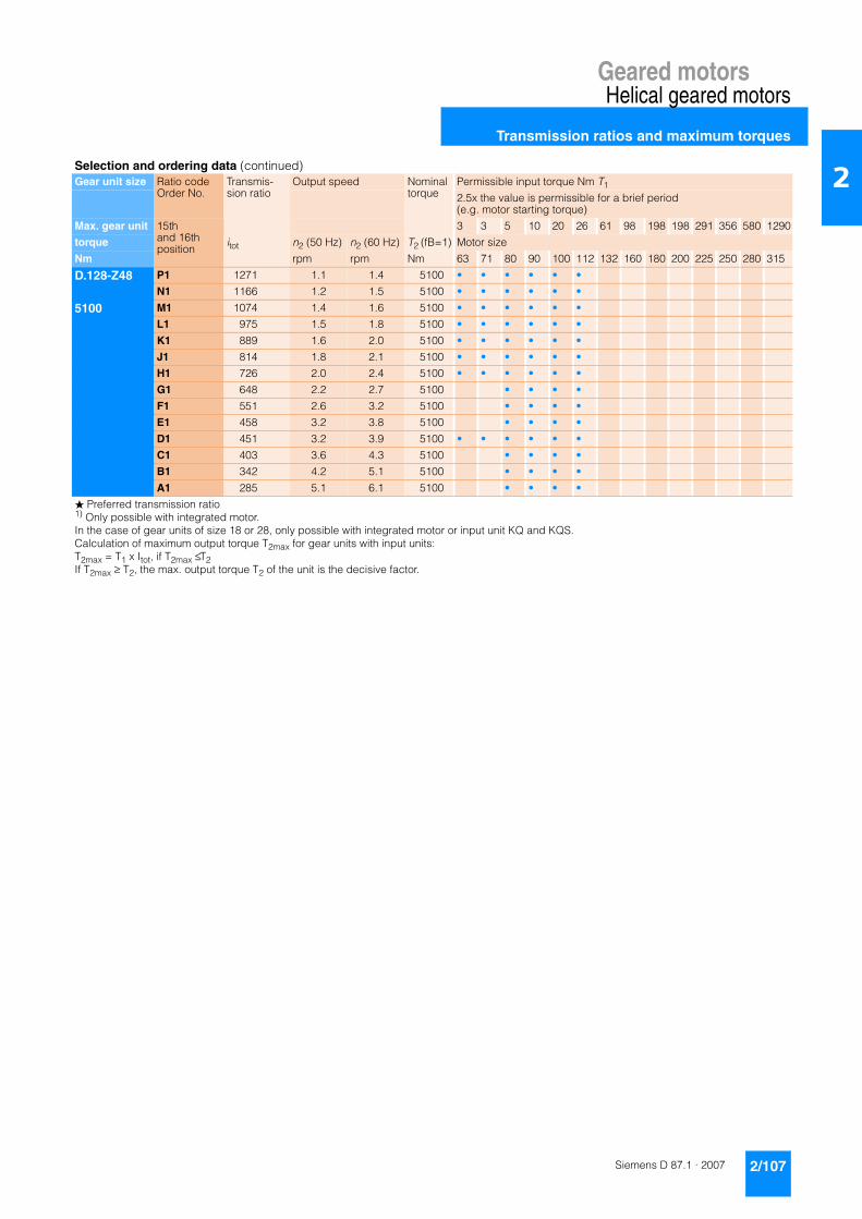
Geared motorsHelical geared motors
Transmission ratios and maximum torques
2/107Siemens D 87.1 · 2007
2
D.128-Z48 P1 1271 1.1 1.4 5100 • • • • • •
N1 1166 1.2 1.5 5100 • • • • • •
5100 M1 1074 1.4 1.6 5100 • • • • • •
L1 975 1.5 1.8 5100 • • • • • •
K1 889 1.6 2.0 5100 • • • • • •
J1 814 1.8 2.1 5100 • • • • • •
H1 726 2.0 2.4 5100 • • • • • •
G1 648 2.2 2.7 5100 • • • •
F1 551 2.6 3.2 5100 • • • •
E1 458 3.2 3.8 5100 • • • •
D1 451 3.2 3.9 5100 • • • • • •
C1 403 3.6 4.3 5100 • • • •
B1 342 4.2 5.1 5100 • • • •
A1 285 5.1 6.1 5100 • • • •
Selection and ordering data (continued)Gear unit size Ratio code
Order No.Transmis-sion ratio
Output speed Nominal torque
Permissible input torque Nm T1
2.5x the value is permissible for a brief period (e.g. motor starting torque)
Max. gear unit 15th and 16thposition
3 3 5 10 20 26 61 98 198 198 291 356 580 1290
torque itot n2 (50 Hz) n2 (60 Hz) T2 (fB=1) Motor size
Nm rpm rpm Nm 63 71 80 90 100 112 132 160 180 200 225 250 280 315
� Preferred transmission ratio1) Only possible with integrated motor.In the case of gear units of size 18 or 28, only possible with integrated motor or input unit KQ and KQS.Calculation of maximum output torque T2max for gear units with input units:T2max = T1 x Itot, if T2max ≤ T2If T2max ≥ T2, the max. output torque T2 of the unit is the decisive factor.

Geared motorsHelical geared motors
Transmission ratios and maximum torques
2/108 Siemens D 87.1 · 2007
2
D.128 K1 268.16 ★ 5.4 6.5 5100 • • •
T1 245.93 5.9 7.1 5100 • • •
5100 S1 219.72 ★ 6.6 8.0 5100 • • • •
R1 201.22 7.2 8.7 5100 • • • •
Q1 185.36 ★ 7.8 9.4 5100 • • • •
P1 171.62 8.4 10.2 5100 • • • •
N1 159.60 ★ 9.1 11.0 5100 • • • • •
M1 148.99 9.7 11.7 5100 • • • • •
L1 133.30 ★ 10.9 13.1 5100 • • • • • • •
K1 123.53 11.7 14.2 5100 • • • • • • •
J1 113.24 ★ 12.8 15.5 5100 • • • • • • •
H1 103.80 14.0 16.9 5100 • • • • • • •
G1 88.46 16.4 19.8 5100 • • • • • • •
F1 78.06 ★ 18.6 22.0 5100 • • • • • • •
E1 66.43 22.0 26.0 5100 • • • • • •
D1 57.56 ★ 25.0 30.0 5100 • • • • • •
C1 48.44 ★ 30.0 36.0 5100 • • • • • •
B1 43.71 33.0 40.0 5100 • • • •
A1 37.57 ★ 39.0 47.0 5100 • • • •
Z.128 D2 44.19 ★ 33 40 3275 • • •
C2 40.96 35 43 3196 • • •
2220 … 5100 B2 38.94 ★ 37 5 5100 • • • •
A2 36.39 40 48 5100 • • • •
X1 32.11 ★ 45 55 5100 • • • • • •
W1 30.28 48 58 5100 • • • • • •
V1 27.13 ★ 53 65 5100 • • • • • • •
U1 25.05 58 70 5100 • • • • • • •
T1 21.41 68 82 5100 • • • • • • • • 1)
S1 19.35 ★ 75 90 5100 • • • • • • • • 1)
R1 18.64 78 94 5100 • • • • • • • 1)
Q1 16.12 90 109 4993 • • • • • • • • 1)
P1 14.06 ★ 103 124 4868 • • • • • • • • 1)
N1 12.03 ★ 121 145 4716 • • • • • • • • 1)
M1 10.78 135 162 4603 • • • • • • 1)
L1 9.13 ★ 159 192 4425 • • • • • • 1)
K1 7.88 184 222 4258 • • • • • 1)
J1 7.29 ★ 199 240 2540 • • • • • 1)
H1 6.24 ★ 232 280 2530 • • • • • 1)
G1 5.93 ★ 245 295 3908 • • • • • 1)
F1 5.59 ★ 259 313 2607 • • • • • 1)
E1 4.83 300 362 2512 • • • • • 1)
D1 4.73 ★ 307 370 2375 • • • • • 1)
C1 4.09 ★ 355 428 2360 • • • • • 1)
B1 3.63 ★ 399 482 2310 • • • • • 1)
A1 3.07 ★ 472 570 2220 • • • • • 1)
Selection and ordering data (continued)Gear unit size Ratio code
Order No.Transmis-sion ratio
Output speed Nominal torque
Permissible input torque Nm T1
2.5x the value is permissible for a brief period (e.g. motor starting torque)
Max. gear unit 15th and 16thposition
3 3 5 10 20 26 61 98 198 198 291 356 580 1290
torque itot n2 (50 Hz) n2 (60 Hz) T2 (fB=1) Motor size
Nm rpm rpm Nm 63 71 80 90 100 112 132 160 180 200 225 250 280 315
� Preferred transmission ratio1) Only possible with integrated motor.In the case of gear units of size 18 or 28, only possible with integrated motor or input unit KQ and KQS.Calculation of maximum output torque T2max for gear units with input units:T2max = T1 x Itot, if T2max ≤ T2If T2max ≥ T2, the max. output torque T2 of the unit is the decisive factor.
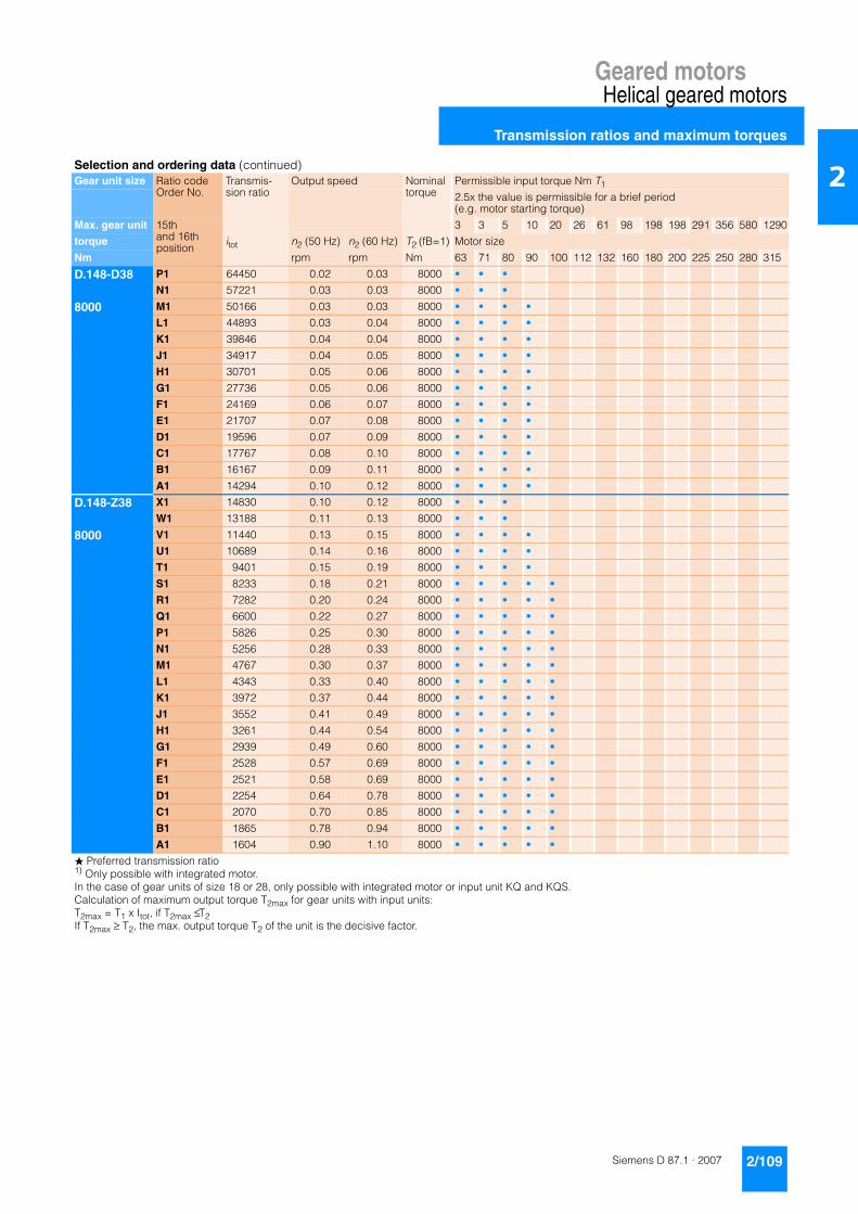
Geared motorsHelical geared motors
Transmission ratios and maximum torques
2/109Siemens D 87.1 · 2007
2
D.148-D38 P1 64450 0.02 0.03 8000 • • •
N1 57221 0.03 0.03 8000 • • •
8000 M1 50166 0.03 0.03 8000 • • • •
L1 44893 0.03 0.04 8000 • • • •
K1 39846 0.04 0.04 8000 • • • •
J1 34917 0.04 0.05 8000 • • • •
H1 30701 0.05 0.06 8000 • • • •
G1 27736 0.05 0.06 8000 • • • •
F1 24169 0.06 0.07 8000 • • • •
E1 21707 0.07 0.08 8000 • • • •
D1 19596 0.07 0.09 8000 • • • •
C1 17767 0.08 0.10 8000 • • • •
B1 16167 0.09 0.11 8000 • • • •
A1 14294 0.10 0.12 8000 • • • •
D.148-Z38 X1 14830 0.10 0.12 8000 • • •
W1 13188 0.11 0.13 8000 • • •
8000 V1 11440 0.13 0.15 8000 • • • •
U1 10689 0.14 0.16 8000 • • • •
T1 9401 0.15 0.19 8000 • • • •
S1 8233 0.18 0.21 8000 • • • • •
R1 7282 0.20 0.24 8000 • • • • •
Q1 6600 0.22 0.27 8000 • • • • •
P1 5826 0.25 0.30 8000 • • • • •
N1 5256 0.28 0.33 8000 • • • • •
M1 4767 0.30 0.37 8000 • • • • •
L1 4343 0.33 0.40 8000 • • • • •
K1 3972 0.37 0.44 8000 • • • • •
J1 3552 0.41 0.49 8000 • • • • •
H1 3261 0.44 0.54 8000 • • • • •
G1 2939 0.49 0.60 8000 • • • • •
F1 2528 0.57 0.69 8000 • • • • •
E1 2521 0.58 0.69 8000 • • • • •
D1 2254 0.64 0.78 8000 • • • • •
C1 2070 0.70 0.85 8000 • • • • •
B1 1865 0.78 0.94 8000 • • • • •
A1 1604 0.90 1.10 8000 • • • • •
Selection and ordering data (continued)Gear unit size Ratio code
Order No.Transmis-sion ratio
Output speed Nominal torque
Permissible input torque Nm T1
2.5x the value is permissible for a brief period (e.g. motor starting torque)
Max. gear unit 15th and 16thposition
3 3 5 10 20 26 61 98 198 198 291 356 580 1290
torque itot n2 (50 Hz) n2 (60 Hz) T2 (fB=1) Motor size
Nm rpm rpm Nm 63 71 80 90 100 112 132 160 180 200 225 250 280 315
� Preferred transmission ratio1) Only possible with integrated motor.In the case of gear units of size 18 or 28, only possible with integrated motor or input unit KQ and KQS.Calculation of maximum output torque T2max for gear units with input units:T2max = T1 x Itot, if T2max ≤ T2If T2max ≥ T2, the max. output torque T2 of the unit is the decisive factor.
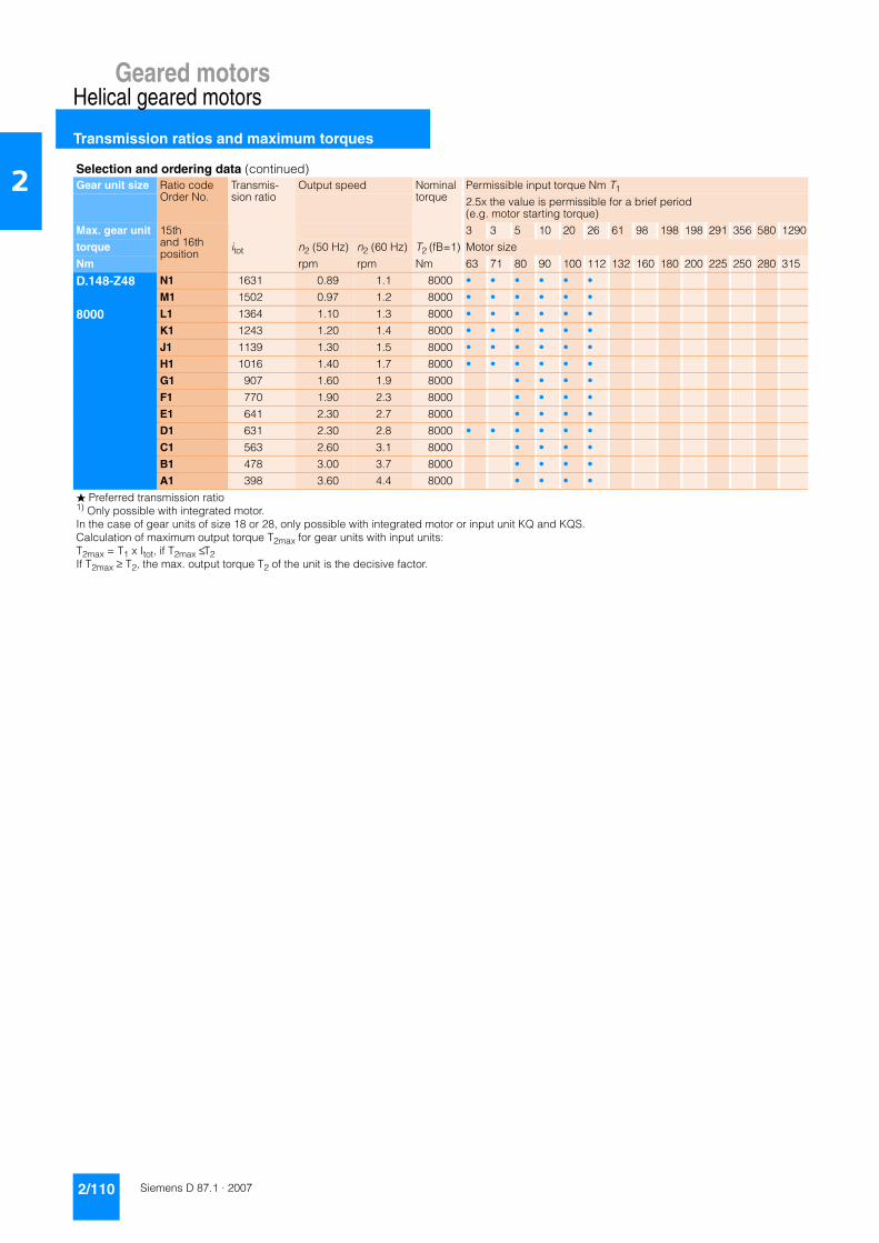
Geared motorsHelical geared motors
Transmission ratios and maximum torques
2/110 Siemens D 87.1 · 2007
2
D.148-Z48 N1 1631 0.89 1.1 8000 • • • • • •
M1 1502 0.97 1.2 8000 • • • • • •
8000 L1 1364 1.10 1.3 8000 • • • • • •
K1 1243 1.20 1.4 8000 • • • • • •
J1 1139 1.30 1.5 8000 • • • • • •
H1 1016 1.40 1.7 8000 • • • • • •
G1 907 1.60 1.9 8000 • • • •
F1 770 1.90 2.3 8000 • • • •
E1 641 2.30 2.7 8000 • • • •
D1 631 2.30 2.8 8000 • • • • • •
C1 563 2.60 3.1 8000 • • • •
B1 478 3.00 3.7 8000 • • • •
A1 398 3.60 4.4 8000 • • • •
Selection and ordering data (continued)Gear unit size Ratio code
Order No.Transmis-sion ratio
Output speed Nominal torque
Permissible input torque Nm T1
2.5x the value is permissible for a brief period (e.g. motor starting torque)
Max. gear unit 15th and 16thposition
3 3 5 10 20 26 61 98 198 198 291 356 580 1290
torque itot n2 (50 Hz) n2 (60 Hz) T2 (fB=1) Motor size
Nm rpm rpm Nm 63 71 80 90 100 112 132 160 180 200 225 250 280 315
� Preferred transmission ratio1) Only possible with integrated motor.In the case of gear units of size 18 or 28, only possible with integrated motor or input unit KQ and KQS.Calculation of maximum output torque T2max for gear units with input units:T2max = T1 x Itot, if T2max ≤ T2If T2max ≥ T2, the max. output torque T2 of the unit is the decisive factor.

Geared motorsHelical geared motors
Transmission ratios and maximum torques
2/111Siemens D 87.1 · 2007
2
D.148 W1 336.11 4.3 5.2 8000 • •
V1 301.34 ★ 4.8 5.8 8000 • • •
8000 U1 276.23 5.2 6.3 8000 • • •
T1 254.70 ★ 5.7 6.9 8000 • • •
S1 236.05 6.1 7.4 8000 • • •
R1 224.43 ★ 6.5 7.8 8000 • • • •
Q1 209.76 6.9 8.3 8000 • • • •
P1 185.03 ★ 7.8 9.5 8000 • • • • • •
N1 174.53 8.3 10.0 8000 • • • • • •
M1 156.38 ★ 9.3 11.2 8000 • • • • • • •
L1 144.39 10.0 12.1 8000 • • • • • • •
K1 123.37 11.8 14.2 8000 • • • • • • •
J1 111.50 ★ 13.0 15.7 8000 • • • • • • •
H1 107.42 13.5 16.3 8000 • • • • • •
G1 92.91 15.6 18.8 8000 • • • • • • •
F1 81.04 ★ 17.9 22.0 8000 • • • • • • •
E1 69.36 ★ 21.0 25.0 8000 • • • • • • •
D1 62.12 23.0 28.0 8000 • • • • •
C1 52.61 ★ 28.0 33.0 8000 • • • • •
B1 45.44 32.0 39.0 8000 • • • •
A1 34.15 ★ 42.0 51.0 8000 • • • •
Z.148 B2 57.50 25 30 4664 •
A2 54.24 ★ 27 32 8000 • •
3850 … 8000 X1 50.74 29 34 8000 • •
W1 45.11 ★ 32 39 8000 • • • •
V1 42.59 34 41 8000 • • • •
U1 38.23 ★ 38 46 8000 • • • • •
T1 35.09 41 50 8000 • • • • •
S1 30.28 48 58 8000 • • • • • •
R1 26.49 55 66 8000 • • • • • •
Q1 23.04 63 76 8000 • • • • • • •
R1 20.21 ★ 72 87 8000 • • • • • • •
N1 17.09 ★ 85 102 8000 • • • • • • •
M1 15.51 93 113 8000 • • • • • • •
L1 13.52 ★ 107 129 8000 • • • • • • •
K1 11.48 126 152 8000 • • • • • •
J1 8.79 ★ 165 199 8000 • • • • • •
H1 8.64 ★ 168 203 4800 • • • • • • •
G1 7.84 ★ 185 223 4800 • • • • • • •
F1 7.57 ★ 192 231 5600 • • • • • •
E1 6.84 ★ 212 256 4800 • • • • • • •
D1 6.43 226 272 5400 • • • • • •
C1 5.80 ★ 250 302 4200 • • • • • •
B1 4.92 ★ 295 356 5050 • • • • • •
A1 4.44 ★ 327 394 3850 • • • • • •
Selection and ordering data (continued)Gear unit size Ratio code
Order No.Transmis-sion ratio
Output speed Nominal torque
Permissible input torque Nm T1
2.5x the value is permissible for a brief period (e.g. motor starting torque)
Max. gear unit 15th and 16thposition
3 3 5 10 20 26 61 98 198 198 291 356 580 1290
torque itot n2 (50 Hz) n2 (60 Hz) T2 (fB=1) Motor size
Nm rpm rpm Nm 63 71 80 90 100 112 132 160 180 200 225 250 280 315
� Preferred transmission ratio1) Only possible with integrated motor.In the case of gear units of size 18 or 28, only possible with integrated motor or input unit KQ and KQS.Calculation of maximum output torque T2max for gear units with input units:T2max = T1 x Itot, if T2max ≤ T2If T2max ≥ T2, the max. output torque T2 of the unit is the decisive factor.

Geared motorsHelical geared motors
Transmission ratios and maximum torques
2/112 Siemens D 87.1 · 2007
2
D.168-D48 P1 71317 ★ 0.02 0.02 14000 • • •
N1 63421 0.02 0.03 14000 • • •
14000 M1 55016 ★ 0.03 0.03 14000 • • • •
L1 51404 0.03 0.03 14000 • • • •
K1 45210 ★ 0.03 0.04 14000 • • • •
J1 39595 0.04 0.04 14000 • • • • •
H1 35022 ★ 0.04 0.05 14000 • • • • •
G1 31740 0.05 0.06 14000 • • • • •
F1 28017 ★ 0.05 0.06 14000 • • • • •
E1 25274 0.06 0.07 14000 • • • • •
D1 22923 ★ 0.06 0.08 14000 • • • • •
C1 20886 0.07 0.08 14000 • • • • •
B1 19103 ★ 0.08 0.09 14000 • • • • •
A1 17080 0.08 0.10 14000 • • • • •
D.168-Z48 A2 17519 0.08 0.10 14000 • • •
X1 15504 ★ 0.09 0.11 14000 • • • •
14000 W1 14094 0.10 0.12 14000 • • • •
V1 12661 ★ 0.11 0.14 14000 • • • •
U1 10853 0.13 0.16 14000 • • • • •
T1 9819 ★ 0.15 0.18 14000 • • • • • •
S1 9064 0.16 0.19 14000 • • • • • •
R1 7881 ★ 0.18 0.22 14000 • • • • • •
Q1 7156 0.20 0.24 14000 • • • • • •
P1 6534 ★ 0.22 0.27 14000 • • • • • •
N1 5995 0.24 0.29 14000 • • • • • •
M1 5523 ★ 0.26 0.32 14000 • • • • • •
L1 5016 0.29 0.35 14000 • • • • • •
K1 4569 ★ 0.32 0.38 14000 • • • • • •
J1 4186 0.35 0.42 14000 • • • • • •
H1 3735 ★ 0.39 0.47 14000 • • • • • •
G1 3333 0.44 0.53 14000 • • • •
F1 2831 0.51 0.62 14000 • • • •
E1 2357 ★ 0.62 0.74 14000 • • • •
D1 2319 ★ 0.63 0.75 14000 • • • • • •
C1 2070 0.70 0.85 14000 • • • •
B1 1758 0.82 1.00 14000 • • • •
A1 1463 ★ 0.99 1.20 14000 • • • •
D.168-Z68 H1 1226 1.2 1.4 14000 • • • • •
G1 1046 1.4 1.7 14000 • • • • •
14000 F1 871 1.7 2.0 14000 • • •
E1 722 2.0 2.4 14000 • • •
D1 637 2.3 2.7 14000 • • • • •
C1 544 2.7 3.2 14000 • • • • •
B1 453 3.2 3.9 14000 • • •
A1 376 3.9 4.7 14000 • • •
Selection and ordering data (continued)Gear unit size Ratio code
Order No.Transmis-sion ratio
Output speed Nominal torque
Permissible input torque Nm T1
2.5x the value is permissible for a brief period (e.g. motor starting torque)
Max. gear unit 15th and 16thposition
3 3 5 10 20 26 61 98 198 198 291 356 580 1290
torque itot n2 (50 Hz) n2 (60 Hz) T2 (fB=1) Motor size
Nm rpm rpm Nm 63 71 80 90 100 112 132 160 180 200 225 250 280 315
� Preferred transmission ratio1) Only possible with integrated motor.In the case of gear units of size 18 or 28, only possible with integrated motor or input unit KQ and KQS.Calculation of maximum output torque T2max for gear units with input units:T2max = T1 x Itot, if T2max ≤ T2If T2max ≥ T2, the max. output torque T2 of the unit is the decisive factor.

Geared motorsHelical geared motors
Transmission ratios and maximum torques
2/113Siemens D 87.1 · 2007
2
D.168 U1 341.61 ★ 4.2 5.1 14000 •
T1 313.41 4.6 5.6 14000 •
14000 S1 289.23 ★ 5.0 6.1 14000 •
R1 268.29 5.4 6.5 14000 •
Q1 253.08 ★ 5.7 6.9 14000 • •
P1 236.72 6.1 7.4 14000 • •
N1 210.49 ★ 6.9 8.3 14000 • • • •
M1 198.71 7.3 8.8 14000 • • • •
L1 178.38 ★ 8.1 9.8 14000 • • • • •
K1 163.72 8.9 10.7 14000 • • • • •
J1 141.28 10.3 12.4 14000 • • • • •
H1 123.59 11.7 14.2 14000 • • • • •
G1 107.48 13.5 16.3 14000 • • • • •
F1 94.30 ★ 15.4 18.6 14000 • • • • •
E1 79.75 ★ 18.2 22.0 14000 • • • • •
D1 72.36 20.0 24.0 14000 • • • • •
C1 63.08 ★ 23.0 28.0 14000 • • • • •
B1 53.56 27.0 33.0 14000 • • • •
C1 40.99 ★ 35.0 43.0 14000 • • • •
Z.168 V1 46.61 31 38 10100 • • • •
U1 42.09 34 42 14000 • • • • •
6470 … T1 39.45 37 44 14000 • • • • • •
14000 S1 33.88 ★ 43 52 14000 • • • • • •
Q1 29.27 50 60 14000 • • • • • • •
P1 25.84 56 68 14000 • • • • • • •
N1 23.26 ★ 62 75 14000 • • • • • • •
M1 19.30 ★ 75 91 14000 • • • • • • •
L1 17.60 82 99 13826 • • • • • • •
K1 15.44 ★ 94 113 13486 • • • • • • •
J1 13.27 109 132 13081 • • • • • • •
H1 10.34 ★ 140 169 12345 • • • • • •
G1 9.26 ★ 157 189 7850 • • • • • • •
F1 8.21 ★ 177 213 11622 • • • • •
E1 7.20 ★ 201 243 7100 • • • • • •
D1 6.20 ★ 234 282 7507 • • • • • •
C1 5.61 ★ 258 312 6780 • • • • • •
B1 4.93 ★ 294 355 7064 • • • • •
A1 4.46 ★ 325 392 6470 • • • • •
Selection and ordering data (continued)Gear unit size Ratio code
Order No.Transmis-sion ratio
Output speed Nominal torque
Permissible input torque Nm T1
2.5x the value is permissible for a brief period (e.g. motor starting torque)
Max. gear unit 15th and 16thposition
3 3 5 10 20 26 61 98 198 198 291 356 580 1290
torque itot n2 (50 Hz) n2 (60 Hz) T2 (fB=1) Motor size
Nm rpm rpm Nm 63 71 80 90 100 112 132 160 180 200 225 250 280 315
� Preferred transmission ratio1) Only possible with integrated motor.In the case of gear units of size 18 or 28, only possible with integrated motor or input unit KQ and KQS.Calculation of maximum output torque T2max for gear units with input units:T2max = T1 x Itot, if T2max ≤ T2If T2max ≥ T2, the max. output torque T2 of the unit is the decisive factor.

Geared motorsHelical geared motors
Transmission ratios and maximum torques
2/114 Siemens D 87.1 · 2007
2
D.188-D48 P1 50901 ★ 0.03 0.03 20000 • • •
N1 45266 0.03 0.04 20000 • • •
20000 M1 39267 ★ 0.04 0.04 20000 • • • •
C1 36689 0.04 0.05 20000 • • • •
K1 32268 ★ 0.04 0.05 20000 • • • •
I1 28260 0.05 0.06 20000 • • • •
H1 24996 ★ 0.06 0.07 20000 • • • • •
G1 22654 0.06 0.08 20000 • • • • •
F1 19997 ★ 0.07 0.09 20000 • • • • •
E1 18039 0.08 0.10 20000 • • • • •
D1 16361 ★ 0.09 0.11 20000 • • • • •
C1 14907 0.10 0.12 20000 • • • • •
B1 13634 ★ 0.11 0.13 20000 • • • • •
A1 12191 0.12 0.14 20000 • • • • •
D.188-Z48 X1 12504 0.12 0.14 20000 • • •
W1 11066 ★ 0.13 0.16 20000 • • • •
20000 V1 9037 ★ 0.16 0.19 20000 • • • •
U1 7746 0.19 0.23 20000 • • • • •
T1 7008 ★ 0.21 0.25 20000 • • • • • •
S1 6469 0.22 0.27 20000 • • • • • •
R1 5625 ★ 0.26 0.31 20000 • • • • • •
Q1 5107 0.28 0.34 20000 • • • • • •
P1 4663 ★ 0.31 0.38 20000 • • • • • •
N1 4279 0.34 0.41 20000 • • • • • •
M1 3942 ★ 0.37 0.44 20000 • • • • • •
L1 3580 0.41 0.49 20000 • • • • • •
K1 3261 ★ 0.44 0.54 20000 • • • • • •
I1 2988 0.49 0.59 20000 • • • • • •
H1 2666 ★ 0.54 0.66 20000 • • • • • •
G1 2379 0.61 0.74 20000 • • • •
F1 2021 0.72 0.87 20000 • • • •
E1 1682 ★ 0.86 1.00 20000 • • • •
D1 1655 ★ 0.88 1.10 20000 • • • • • •
C1 1477 0.98 1.20 20000 • • • •
B1 1255 1.20 1.40 20000 • • • •
A1 1044 ★ 1.40 1.70 20000 • • • •
D.188-Z68 G1 896 ★ 1.6 2.0 20000 • • • • •
F1 746 1.9 2.3 20000 • • •
20000 E1 619 ★ 2.3 2.8 20000 • • •
D1 546 2.7 3.2 20000 • • • • •
C1 466 ★ 3.1 3.8 20000 • • • • •
B1 388 3.7 4.5 20000 • • •
A1 322 ★ 4.5 5.4 20000 • • •
Selection and ordering data (continued)Gear unit size Ratio code
Order No.Transmis-sion ratio
Output speed Nominal torque
Permissible input torque Nm T1
2.5x the value is permissible for a brief period (e.g. motor starting torque)
Max. gear unit 15th and 16thposition
3 3 5 10 20 26 61 98 198 198 291 356 580 1290
torque itot n2 (50 Hz) n2 (60 Hz) T2 (fB=1) Motor size
Nm rpm rpm Nm 63 71 80 90 100 112 132 160 180 200 225 250 280 315
� Preferred transmission ratio1) Only possible with integrated motor.In the case of gear units of size 18 or 28, only possible with integrated motor or input unit KQ and KQS.Calculation of maximum output torque T2max for gear units with input units:T2max = T1 x Itot, if T2max ≤ T2If T2max ≥ T2, the max. output torque T2 of the unit is the decisive factor.

Geared motorsHelical geared motors
Transmission ratios and maximum torques
2/115Siemens D 87.1 · 2007
2
D.188 N1 243.82 5.9 7.2 20000 • • • •
M1 220.17 6.6 7.9 20000 • • • • •
20000 L1 206.34 7.0 8.5 20000 • • • • • •
K1 177.23 ★ 8.2 9.9 20000 • • • • • •
J1 153.12 9.5 11.4 20000 • • • • • • •
H1 135.16 10.7 13.0 20000 • • • • • • •
G1 121.67 ★ 11.9 14.4 20000 • • • • • • •
F1 100.96 ★ 14.4 17.3 20000 • • • • • • •
E1 92.06 15.8 19.0 20000 • • • • • • •
D1 80.77 ★ 18.0 22.0 20000 • • • • • • •
C1 69.41 21.0 25.0 20000 • • • • • • •
B1 54.06 ★ 27.0 32.0 20000 • • • • • • •
A1 42.95 ★ 34.0 41.0 20000 • • • • • • •
Z.188 P1 52.35 28 33 15710 • • • •
N1 48.22 30 36 15920 • • • • •
13040 … M1 41.85 ★ 35 42 16110 • • • • •
20000 L1 36.89 39 47 16600 • • • • • •
K1 32.37 45 54 18450 • • • • • •
J1 29.18 ★ 50 60 20000 • • • • • •
H1 24.77 ★ 59 71 20000 • • • • • •
G1 23.01 63 76 20000 • • • • • •
F1 19.76 ★ 73 89 20000 • • • • • •
E1 16.86 86 104 20000 • • • • • • •
D1 13.28 ★ 109 132 18820 • • • • • • •
C1 10.69 ★ 136 164 16170 • • • • • •
B1 9.29 156 188 14310 • • • •
A1 8.30 175 211 13040 • • •
Selection and ordering data (continued)Gear unit size Ratio code
Order No.Transmis-sion ratio
Output speed Nominal torque
Permissible input torque Nm T1
2.5x the value is permissible for a brief period (e.g. motor starting torque)
Max. gear unit 15th and 16thposition
3 3 5 10 20 26 61 98 198 198 291 356 580 1290
torque itot n2 (50 Hz) n2 (60 Hz) T2 (fB=1) Motor size
Nm rpm rpm Nm 63 71 80 90 100 112 132 160 180 200 225 250 280 315
� Preferred transmission ratio1) Only possible with integrated motor.In the case of gear units of size 18 or 28, only possible with integrated motor or input unit KQ and KQS.Calculation of maximum output torque T2max for gear units with input units:T2max = T1 x Itot, if T2max ≤ T2If T2max ≥ T2, the max. output torque T2 of the unit is the decisive factor.
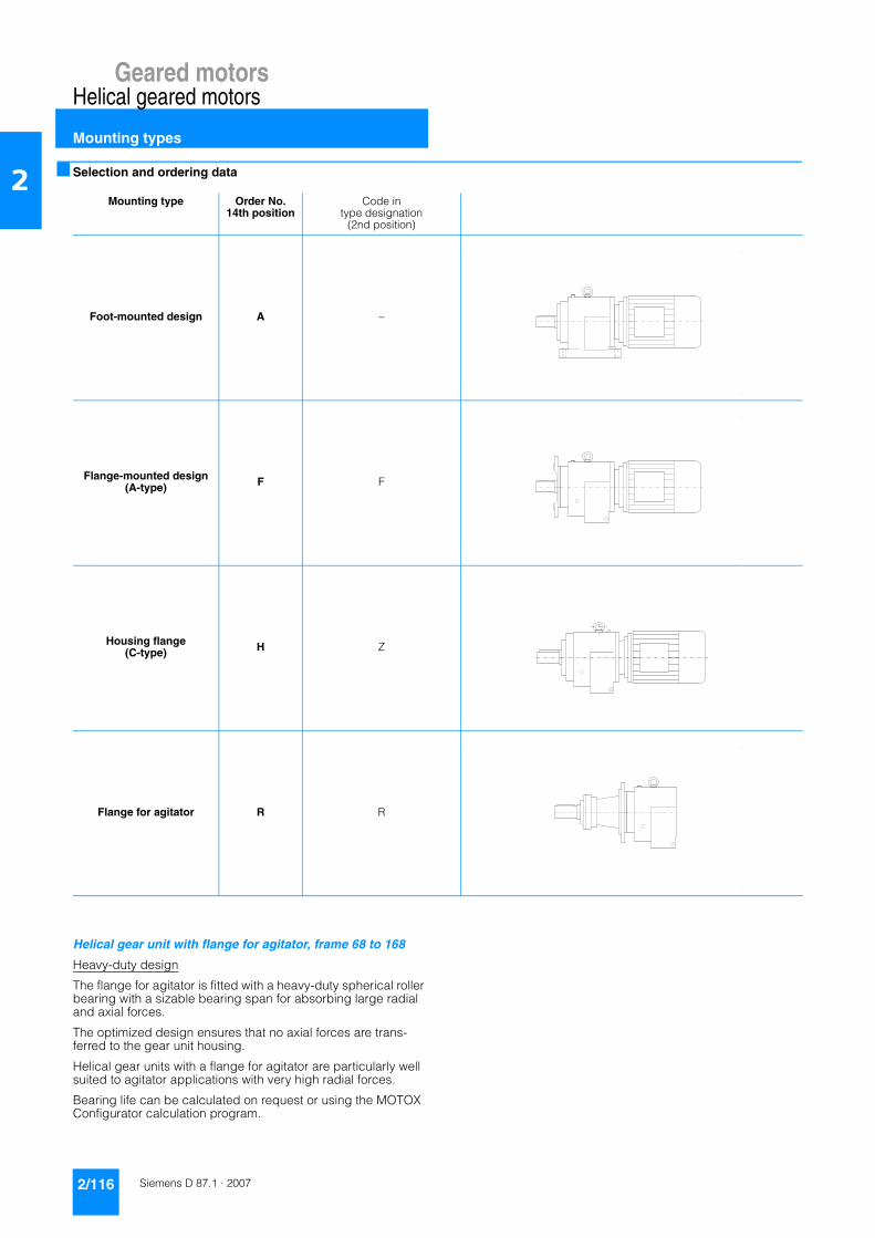
Geared motorsHelical geared motors
Mounting types
2/116 Siemens D 87.1 · 2007
2 ■ Selection and ordering data
Helical gear unit with flange for agitator, frame 68 to 168
Heavy-duty design
The flange for agitator is fitted with a heavy-duty spherical roller bearing with a sizable bearing span for absorbing large radial and axial forces.
The optimized design ensures that no axial forces are trans-ferred to the gear unit housing.
Helical gear units with a flange for agitator are particularly well suited to agitator applications with very high radial forces.
Bearing life can be calculated on request or using the MOTOX Configurator calculation program.
Mounting type Order No. 14th position
Code in type designation
(2nd position)
Foot-mounted design A –
Flange-mounted design(A-type) F F
Housing flange (C-type) H Z
Flange for agitator R R
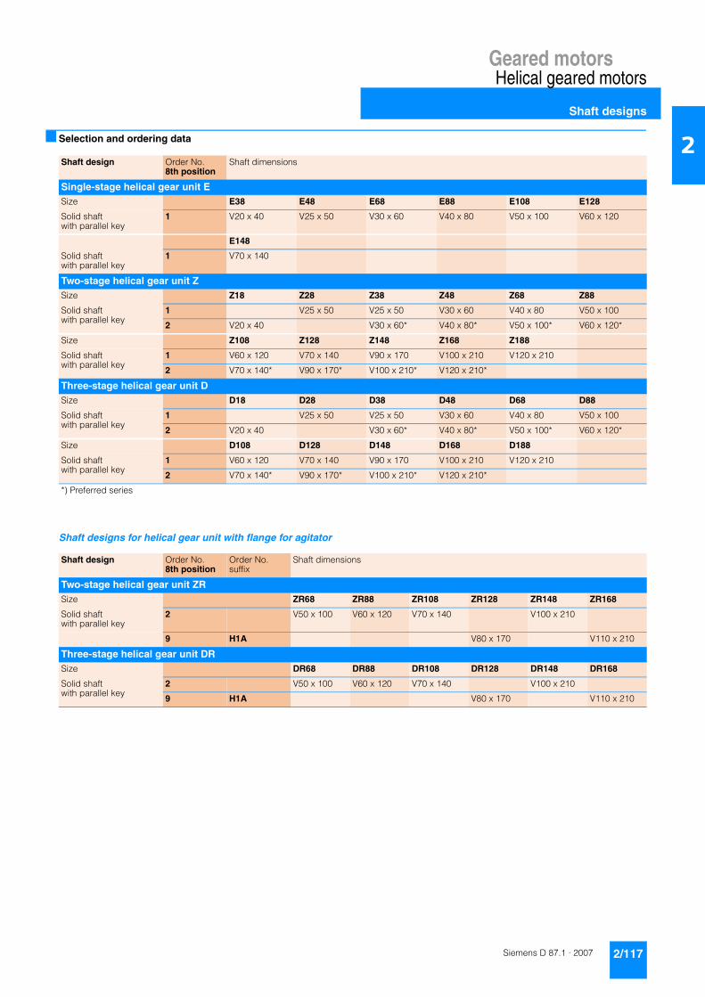
Geared motorsHelical geared motors
Shaft designs
2/117Siemens D 87.1 · 2007
2■ Selection and ordering data
Shaft designs for helical gear unit with flange for agitator
Shaft design Order No. 8th position
Shaft dimensions
Single-stage helical gear unit ESize E38 E48 E68 E88 E108 E128
Solid shaft with parallel key
1 V20 x 40 V25 x 50 V30 x 60 V40 x 80 V50 x 100 V60 x 120
E148
Solid shaft with parallel key
1 V70 x 140
Two-stage helical gear unit ZSize Z18 Z28 Z38 Z48 Z68 Z88
Solid shaft with parallel key
1 V25 x 50 V25 x 50 V30 x 60 V40 x 80 V50 x 100
2 V20 x 40 V30 x 60* V40 x 80* V50 x 100* V60 x 120*
Size Z108 Z128 Z148 Z168 Z188
Solid shaft with parallel key
1 V60 x 120 V70 x 140 V90 x 170 V100 x 210 V120 x 210
2 V70 x 140* V90 x 170* V100 x 210* V120 x 210*
Three-stage helical gear unit DSize D18 D28 D38 D48 D68 D88
Solid shaft with parallel key
1 V25 x 50 V25 x 50 V30 x 60 V40 x 80 V50 x 100
2 V20 x 40 V30 x 60* V40 x 80* V50 x 100* V60 x 120*
Size D108 D128 D148 D168 D188
Solid shaft with parallel key
1 V60 x 120 V70 x 140 V90 x 170 V100 x 210 V120 x 210
2 V70 x 140* V90 x 170* V100 x 210* V120 x 210*
*) Preferred series
Shaft design Order No. 8th position
Order No.suffix
Shaft dimensions
Two-stage helical gear unit ZRSize ZR68 ZR88 ZR108 ZR128 ZR148 ZR168
Solid shaft with parallel key
2 V50 x 100 V60 x 120 V70 x 140 V100 x 210
9 H1A V80 x 170 V110 x 210
Three-stage helical gear unit DRSize DR68 DR88 DR108 DR128 DR148 DR168
Solid shaft with parallel key
2 V50 x 100 V60 x 120 V70 x 140 V100 x 210
9 H1A V80 x 170 V110 x 210

Geared motorsHelical geared motors
Flange-mounted designs (A-type)
2/118 Siemens D 87.1 · 2007
2 ■ Selection and ordering data
Order code Flange diameter
Helical gear unit EF, single-stageSize EF38 EF48 EF68 EF88 EF108 EF128 EF148
H01 120 120
H02 140 140 200 250 300 350 350
H03 160 160 250 300 350 450 450
H04 200 200 300 350 450 550
H05 250 250
Helical gear unit ZF, two-stageSize ZF18 ZF28 ZF38 ZF48 ZF68 ZF88 ZF108 ZF128 ZF148 ZF168 ZF188
H02 120 120 120 550
H03 140 140 140 200 250 300 350 350 450 450 660
H04 160 160 160 250 300 350 450 450 550 550
H05 200 300 350 450 550 660
H06 250
Helical gear unit DF, three-stageSize DF18 DF28 DF38 DF48 DF68 DF88 DF108 DF128 DF148 DF168 DF188
H02 120 120 120 550
H03 140 140 140 200 250 300 350 350 450 450 660
H04 160 160 160 250 300 350 450 450 550 550
H05 200 300 350 450 550 660
H06 250
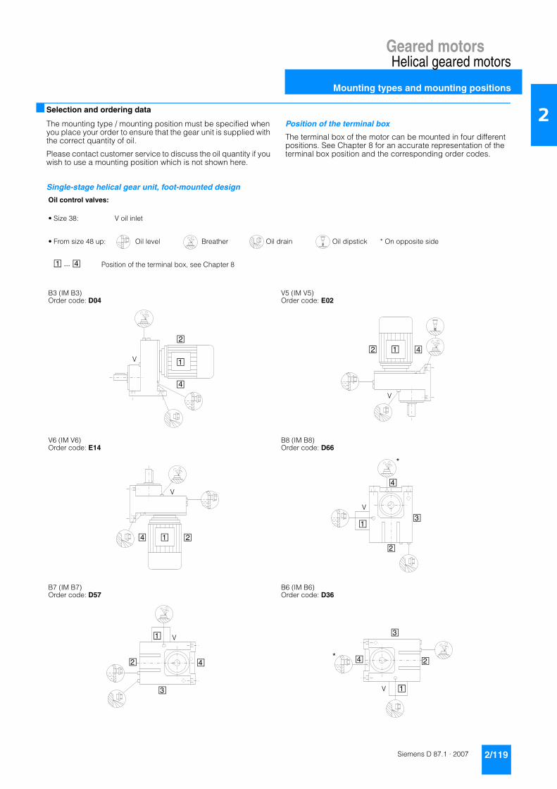
Geared motorsHelical geared motors
Mounting types and mounting positions
2/119Siemens D 87.1 · 2007
2■ Selection and ordering data
The mounting type / mounting position must be specified when you place your order to ensure that the gear unit is supplied with the correct quantity of oil.
Please contact customer service to discuss the oil quantity if you wish to use a mounting position which is not shown here.
Position of the terminal box
The terminal box of the motor can be mounted in four different positions. See Chapter 8 for an accurate representation of the terminal box position and the corresponding order codes.
Single-stage helical gear unit, foot-mounted design
Oil control valves:
• Size 38: V oil inlet
• From size 48 up: Oil level Breather Oil drain Oil dipstick * On opposite side
Position of the terminal box, see Chapter 8
B3 (IM B3)Order code: D04
V5 (IM V5)Order code: E02
V6 (IM V6)Order code: E14
B8 (IM B8)Order code: D66
B7 (IM B7)Order code: D57
B6 (IM B6)Order code: D36
1 ... 4
1
2
4
V2 1 4
V
4 1 2
V
1
2
3
4
V
*
1
2
3
4
V
1
2
3
4
V
*

Geared motorsHelical geared motors
Mounting types and mounting positions
2/120 Siemens D 87.1 · 2007
2Single-stage helical gear unit, flange-mounted design (EF) and with housing flange (EZ)
Oil control valves:
• Size 38: V oil inlet
• From size 48 up: Oil level Breather Oil drain Oil dipstick * On opposite side
2-stage gear unit 3-stage gear unit
Position of the terminal box, see Chapter 8
EF: B5 (IM B5)Order code: D16EZ: B14 (IM B14)Order code: D00
EF: V1 (IM V1)Order code: D88EZ: V18 (IM V18)Order code: D94
EF: V3 (IM V3)Order code: D96EZ: V19 (IM V19)Order code: D95
EF: B5-02 (IM B5-02)Order code: D26EZ: B14-02 (IM B14-02)Order code: D02
EF: B5-03 (IM B5-03)Order code: D31EZ: B14-03 (IM B14-03)Order code: D03
EF: B5-00 (IM B5-00)Order code: D17EZ: B14-00 (IM B14-00)Order code: D01
2 3
1 ... 4
1
4
2
V1 42
V
1 24
V 1
4
3
2
V
1
2
4
3
V
*
4
1
2
3
V
*

Geared motorsHelical geared motors
Mounting types and mounting positions
2/121Siemens D 87.1 · 2007
2■ Selection and ordering data (continued)
Two- and three-stage helical gear unit, foot-mounted design, sizes 38 - 88
Oil control valves:
• Size 18/28: These types are lubricated for life. No breather, oil level, or drain plugs are present.
• Size 38: V oil inlet
• From size 48 up: Oil level Breather Oil drain * On opposite side
2-stage gear unit 3-stage gear unit
Position of the terminal box, see Chapter 8
B3 (IM B3)Order code: D04
V5 (IM V5)Order code: E02
V6 (IM V6)Order code: E14
B8 (IM B8)Order code: D66
B7 (IM B7)Order code: D57
B6 (IM B6)Order code: D36
2 3
1 ... 4
1
4
2V
*
*2
1 42
V3
1 24
V*1
3
4
2
*
V
1
3
42
V
1
3
42
V
*

Geared motorsHelical geared motors
Mounting types and mounting positions
2/122 Siemens D 87.1 · 2007
2 ■ Selection and ordering data (continued)
Two- and three-stage helical gear unit, foot-mounted design, sizes 108 - 168
Oil control valves:
Oil level Breather Oil drain * On opposite side
2-stage gear unit 3-stage gear unit
Position of the terminal box, see Chapter 8
B3 (IM B3)Order code: D04
V5 (IM V5)Order code: E02
V6 (IM V6)Order code: E14
B8 (IM B8)Order code: D66
B7 (IM B7)Order code: D57
B6 (IM B6)Order code: D36
2 3
1 ... 4
1
*
2
4
*
2
31 42
1 24
* 1 3
4
2
*
1
3
42
1
3
42

Geared motorsHelical geared motors
Mounting types and mounting positions
2/123Siemens D 87.1 · 2007
2■ Selection and ordering data (continued)
Two- and three-stage helical gear unit, foot-mounted design, size 188
Oil control valves:
Oil level Breather Oil drain * On opposite side
2-stage gear unit 3-stage gear unit Dual gear unit
Position of the terminal box, see Chapter 8
B3 (IM B3)Order code: D04
V5 (IM V5)Order code: E02
V6 (IM V6)Order code: E14
B8 (IM B8)Order code: D66
B7 (IM B7)Order code: D57
B6 (IM B6)Order code: D36
2 3 4
1 ... 4
1
*
2
4
*
1 42
32
4
1 24
*
1 3
4
2
*
1
3
42
1
3
42

Geared motorsHelical geared motors
Mounting types and mounting positions
2/124 Siemens D 87.1 · 2007
2 ■ Selection and ordering data (continued)
Two- and three-stage helical gear unit, flange-mounted design (DF/ZF) or with housing flange (DZ/ZZ), sizes 38 - 88Oil control valves:
• Size 18/28: These types are lubricated for life. No breather, oil level, or drain plugs are present.
• Size 38: V oil inlet
• From size 48 up: Oil level Breather Oil drain Oil dipstick * On opposite side
DF/ZF: B5 (IM B5)Order code: D16DZ/ZZ: B14 (IM B14)Order code: D00
DF/ZF: V1 (IM V1)Order code: D88DZ/ZZ: V18 (IM V18)Order code: D94
DF/ZF: V3 (IM V3)Order code: D96DZ/ZZ: V19 (IM V19)Order code: D95
1
4
*
2V
*2 3
14
2
V
1 24
*V

Geared motorsHelical geared motors
Mounting types and mounting positions
2/125Siemens D 87.1 · 2007
2■ Selection and ordering data (continued)
Two- and three-stage helical gear unit, flange-mounted design (DF/ZF) or with housing flange (DZ/ZZ), sizes 108 - 168
Oil control valves:
Oil level Breather Oil drain * On opposite side
2-stage gear unit 3-stage gear unit
Position of the terminal box, see Chapter 8
DF/ZF: B5 (IM B5)Order code: D16DZ/ZZ: B14 (IM B14)Order code: D00
DF/ZF: V1 (IM V1)Order code: D88DZ/ZZ: V18 (IM V18)Order code: D94
DF/ZF: V3 (IM V3)Order code: D96DZ/ZZ: V19 (IM V19)Order code: D95
2 3
1 ... 4
1
4
*
2
*
2
31
4
2
1 24
*

Geared motorsHelical geared motors
Mounting types and mounting positions
2/126 Siemens D 87.1 · 2007
2 ■ Selection and ordering data (continued)
Two- and three-stage helical gear unit, flange-mounted design (DF/ZF) or with housing flange (DZ/ZZ), size 188
Oil control valves:
Oil level Breather Oil drain * On opposite side
2-stage gear unit 3-stage gear unit Dual gear unit
Position of the terminal box, see Chapter 8
DF/ZF: B5 (IM B5)Order code: D16DZ/ZZ: B14 (IM B14)Order code: D00
DF/ZF: V1 (IM V1)Order code: D88DZ/ZZ: V18 (IM V18)Order code: D94
DF/ZF: V3 (IM V3)Order code: D96DZ/ZZ: V19 (IM V19)Order code: D95
2 3 4
1 ... 4
1
4
*
2
*
1 42
2 3
4
1 24
*

Geared motorsHelical geared motors
Mounting types and mounting positions
2/127Siemens D 87.1 · 2007
2■ Selection and ordering data (continued)
Two- and three-stage helical gear unit with flange for agitator (DR/ZR), sizes 68 - 88
Oil control valves:
Oil level Breather Oil drain * On opposite side
2-stage gear unit 3-stage gear unit
Position of the terminal box, see Chapter 8
DR/ZR: B5 (IM B5)Order code: D16
DR/ZR: V1 (IM V1)Order code: D88
DR/ZR: V3 (IM V3)Order code: D96
2 3
1 ... 4
1
2
4
*
12 4
*2 3
1 24
*

Geared motorsHelical geared motors
Mounting types and mounting positions
2/128 Siemens D 87.1 · 2007
2 ■ Selection and ordering data (continued)
Two- and three-stage helical gear unit with flange for agitator (DR/ZR), sizes 108 - 168
Oil control valves:
Oil level Breather Oil drain * On opposite side
2-stage gear unit 3-stage gear unit
Position of the terminal box, see Chapter 8
DR/ZR: B5 (IM B5)Order code: D16
DR/ZR: V1 (IM V1)Order code: D88
DR/ZR: V3 (IM V3)Order code: D96
2 3
1 ... 4
1
2
4
*
124
*
2
3
1 24
*

Geared motorsHelical geared motors
Mounting types and mounting positions
2/129Siemens D 87.1 · 2007
2■ Selection and ordering data (continued)
Helical dual gear unit
The mounting type / mounting position of the dual gear unit corresponds to that of the main gear unit. The figures below are only designed to show the position of the oil control valves of the 2nd gear unit.
Note:
In a horizontal operating position the bulging part of the housing of the 2nd gear unit generally faces vertically downwards.
Oil control valves:
• Size 28/38 (2nd gear unit): These types are lubricated for life. No breather, oil level, or drain plugs are present.
• From size 48 up: Oil level Breather Oil drain * On opposite side
2-stage gear unit 3-stage gear unit
Position of the terminal box, see Chapter 8
2 3
1 ... 4
Main gear unit
*
*
*2 3
Main gear unit
Main gear unit

Geared motorsHelical geared motors
Special versions
2/130 Siemens D 87.1 · 2007
2 ■ Lubricants
Helical gear units are filled with mineral oil and supplied ready for use as standard.
If the gear unit is to be used in an application with special re-quirements, the lubricants listed in the table below can be used.
1) Recommendation 2) On request
Gear units of sizes 48 to 188 are fitted with filler, oil level, and drain plugs as standard. The ventilation and breather filter, which is delivered loose, must be attached in place of the filler plug prior to startup.
Sizes 18 to 28 do not feature any breather, oil level, or drain plugs. The lubricant does not need to be changed, due to the low thermal load the gear unit is subjected to.
Helical gear units of size 38 have an oil screw; these gear units do not require ventilation or breather elements.
■ Oil level control
Oil sight glass
For size 48 and above, gear units can be equipped with a visual oil level indicator (oil sight glass) for most mounting types and mounting positions.
Order code G34
Electrical oil level monitoring system
If required, the gear unit can be supplied with an electrical oil level monitoring system, which enables the oil level of the gear unit to be monitored remotely. The oil level is monitored by a ca-pacitive sensor only when the gear unit starts up; it is not mea-sured continuously during operation.
Order codes:
Capacitive sensor G37
Isolation amplifier 24 V G39
■ Gear unit ventilation
The positions of the ventilation and breather elements can be seen on the mounting position diagrams.
If required, a pressure breather valve can be used for size 48 and above.
Order codes:
Breather filter G44
Pressure breather valve G45
Area of application Ambient temperature 1) DIN ISO designation Order code
Standard oilsStandard temperature -10 to +40°C CLP ISO VG 220 K06
Improved oil service life -20 to +50°C CLP ISO PG VG 220 K07
High temperature usage 0 to +60°C CLP ISO PG VG 460 K08
Low temperature usage -30 to +50°C CLP ISO PAO VG 220 K12 2)
Lowest temperature usage -40 to +40°C CLP ISO PAO VG 68 K13 2)
Physiologically safe oils (for use in the food industry) in acc. with USDA-H1Standard temperature -30 to +40°C CLP ISO PAO VG 460 K10 2)
Biologically degradable oilsStandard temperature -20 to +40°C CLP ISO E VG 220 K11 2)
� � �
� � �
��
�
���������� �
� � �
�
� � �
��
����������
Gear unit Size
Helical gear unit E.48 … E.128D./Z.48 … D./Z.128
Gear unit Size
Helical gear unit E.148D./Z.148 … D./Z.188

Geared motorsHelical geared motors
Special versions
2/131Siemens D 87.1 · 2007
2■ Oil drain
Magnetic screw plug
A magnetic screw plug for inserting in the oil drainage hole is available on request for helical gear units of size 48 and above. This serves to collect any metal grit contained in the gear lubri-cant.
Order code G53
Oil drain valve
An oil drain valve is available on request for helical gear units of size 48 and above.
The plug valve may be designed as a complete unit featuring a screw plug, depending on the corresponding mounting position.
Order code:
Oil drain valve, straight G54
Item 1 Oil drain valve Item 2 Screwed joint EGEItem 3 Screwed joint GE Item 4 Screw plug
An angled oil drain valve is also available on request.
Item 1 Oil drain valve Item 2 Screwed joint EGEItem 3 Screwed joint GE Item 4 Screw plug
■ Sealing
Combination of seals
A combination of seals, which helps to prevent oil from leaking, is available for helical gear units of sizes 38 to 168.
A combination of seals is particularly well suited to external use.Order code G24
Dual sealing
Dual sealing is possible for helical gear units of sizes 18, 28, and 188. Dual sealing is particularly well suited to external use.Order code G23
Viton sealing
Viton seals (fluorinated rubber) for high operating and ambient temperatures of +60 °C and above are available for helical gear units.Order code G25
3 2 1 4
32 1 4
3
4
2
4 1
G_M
015_
EN_0
0182
a
1
2
3
4
Housing
Shaft
protected running surface for radial shaft sealing ringno damage when mounting
additional sealing lips to protect against dirtdecoupled sealing system prevents scoring of the shaft asa result of corrosion or dirt
rubberized inner and outer diameter
grease filling prevents dry running of the sealing lips

Geared motorsHelical geared motors
Special versions
2/132 Siemens D 87.1 · 2007
2 ■ Radial reinforced output bearings
If required, gear units are available with a reinforced output shaft bearing arrangement. The reinforced bearings allow higher ra-dial forces to be transferred.
Order code G20
■ Flange for agitator in dry-well design
The flange for agitator can be fitted with an additional "V" ring (1) in mounting position V1 in order to drain off any leak oil to a safety chamber and protect the equipment against the effects of leakages.
The oil can either be viewed through a sight glass, or its presence indicated by an electrical sensor (2).
Order codes:
Design with sight glass: G89
Design with sensor: G90
Regreasing device for the flange for agitator
The flange for agitator gear unit can be fitted with a regreasing device on request.
2 1 3

Geared motorsHelical geared motors
Dimensions
2/133Siemens D 87.1 · 2007
2■ Dimension drawing overview
Gear unit type Dimension drawing on page
E38 2/135
E48 2/138
E68 2/141
E88 2/144
E108 2/147
E128 2/150
E148 2/153
EF38 2/136
EF48 2/139
EF68 2/142
EF88 2/145
EF108 2/148
EF128 2/151
EF148 2/154
EZ38 2/137
EZ48 2/140
EZ68 2/143
EZ88 2/146
EZ108 2/149
EZ128 2/152
EZ148 2/155
D/Z18 2/156
D/Z28 2/158
D/Z38 2/160
D/Z48 2/163
D/Z68 2/166
D/Z88 2/169
D/Z108 2/172
D/Z128 2/175
D/Z148 2/178
D/Z168 2/181
D/Z188 2/184
DF/ZF18 2/157
DF/ZF28 2/159
DF/ZF38 2/161
DF/ZF48 2/164
DF/ZF68 2/167
DF/ZF88 2/170
DF/ZF108 2/173
DF/ZF128 2/176
DF/ZF148 2/179
DF/ZF168 2/182
DF/ZF188 2/185

Geared motorsHelical geared motors
Dimensions
2/134 Siemens D 87.1 · 2007
2 ■ Dimension drawing overview (continued)
Gear unit type Dimension drawing on page
DZ/ZZ38 2/162
DZ/ZZ48 2/165
DZ/ZZ68 2/168
DZ/ZZ88 2/171
DZ/ZZ108 2/174
DZ/ZZ128 2/177
DZ/ZZ148 2/180
DZ/ZZ168 2/183
DZ/ZZ188 2/186
2/187D./Z.38-Z28 ... Z.188-Z68
2/190DR/ZR88 ... DR/ZR168
Pin holes 2/191

Geared motorsHelical geared motors
Dimensions
2/135Siemens D 87.1 · 2007
2■ Gear unit E38 (single-stage), foot-mounted design
E011
E38 Weight
Motor k kB AC AD AG LL HH DV E38
LA71 368.5 423.5 139.0 146 90 90 114.5 M20x1.5/M25x2.5 12
LA71Z 387.5 442.5 139.0 146 90 90 114.5 M20x1.5/M25x2.5 12
LA80 405.5 469.0 156.5 155 90 90 114.0 M20x1.5/M25x2.5 16
LA90S 436.5 507.5 174.0 163 90 90 114.0 M20x1.5/M25x2.5 21
LA90L 436.5 507.5 174.0 163 90 90 114.0 M20x1.5/M25x2.5 21
LA90ZL 481.5 552.5 174.0 163 90 90 114.0 M20x1.5/M25x2.5 24
LA100L 482.5 563.5 195.0 168 120 120 154.5 2xM32x1.5 30
LA112M 512.5 593.5 219.0 181 120 120 160.5 2xM32x1.5 41
➃ DIN 332 ➄ Parallel key / keyway DIN 6885
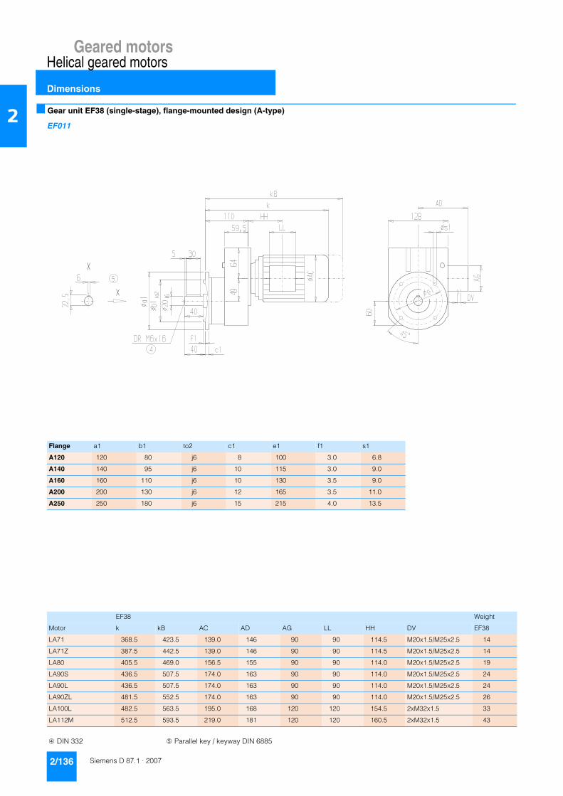
Geared motorsHelical geared motors
Dimensions
2/136 Siemens D 87.1 · 2007
2 ■ Gear unit EF38 (single-stage), flange-mounted design (A-type)
EF011
Flange a1 b1 to2 c1 e1 f1 s1
A120 120 80 j6 8 100 3.0 6.8
A140 140 95 j6 10 115 3.0 9.0
A160 160 110 j6 10 130 3.5 9.0
A200 200 130 j6 12 165 3.5 11.0
A250 250 180 j6 15 215 4.0 13.5
EF38 Weight
Motor k kB AC AD AG LL HH DV EF38
LA71 368.5 423.5 139.0 146 90 90 114.5 M20x1.5/M25x2.5 14
LA71Z 387.5 442.5 139.0 146 90 90 114.5 M20x1.5/M25x2.5 14
LA80 405.5 469.0 156.5 155 90 90 114.0 M20x1.5/M25x2.5 19
LA90S 436.5 507.5 174.0 163 90 90 114.0 M20x1.5/M25x2.5 24
LA90L 436.5 507.5 174.0 163 90 90 114.0 M20x1.5/M25x2.5 24
LA90ZL 481.5 552.5 174.0 163 90 90 114.0 M20x1.5/M25x2.5 26
LA100L 482.5 563.5 195.0 168 120 120 154.5 2xM32x1.5 33
LA112M 512.5 593.5 219.0 181 120 120 160.5 2xM32x1.5 43
➃ DIN 332 ➄ Parallel key / keyway DIN 6885

Geared motorsHelical geared motors
Dimensions
2/137Siemens D 87.1 · 2007
2■ Gear unit EZ38 (single-stage), housing-flange-mounted design (C-type)
EZ011
EZ38 Weight
Motor k kB AC AD AG LL HH DV EZ38
LA71 368.5 423.5 139.0 146 90 90 114.5 M20x1.5/M25x2.5 11
LA71Z 387.5 442.5 139.0 146 90 90 114.5 M20x1.5/M25x2.5 11
LA80 405.5 469.0 156.5 155 90 90 114.0 M20x1.5/M25x2.5 16
LA90S 436.5 507.5 174.0 163 90 90 114.0 M20x1.5/M25x2.5 20
LA90L 436.5 507.5 174.0 163 90 90 114.0 M20x1.5/M25x2.5 20
LA90ZL 481.5 552.5 174.0 163 90 90 114.0 M20x1.5/M25x2.5 23
LA100L 482.5 563.5 195.0 168 120 120 154.5 2xM32x1.5 29
LA112M 512.5 593.5 219.0 181 120 120 160.5 2xM32x1.5 40
➃ DIN 332 ➄ Parallel key / keyway DIN 6885
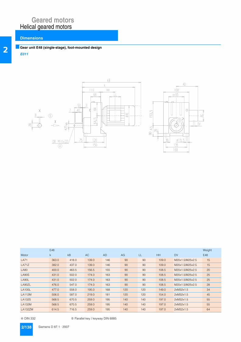
Geared motorsHelical geared motors
Dimensions
2/138 Siemens D 87.1 · 2007
2 ■ Gear unit E48 (single-stage), foot-mounted design
E011
E48 Weight
Motor k kB AC AD AG LL HH DV E48
LA71 363.0 418.0 139.0 146 90 90 109.0 M20x1.5/M25x2.5 15
LA71Z 382.0 437.0 139.0 146 90 90 109.0 M20x1.5/M25x2.5 15
LA80 400.0 463.5 156.5 155 90 90 108.5 M20x1.5/M25x2.5 20
LA90S 431.0 502.0 174.0 163 90 90 108.5 M20x1.5/M25x2.5 25
LA90L 431.0 502.0 174.0 163 90 90 108.5 M20x1.5/M25x2.5 25
LA90ZL 476.0 547.0 174.0 163 90 90 108.5 M20x1.5/M25x2.5 28
LA100L 477.0 558.0 195.0 168 120 120 149.0 2xM32x1.5 34
LA112M 506.0 587.0 219.0 181 120 120 154.0 2xM32x1.5 45
LA132S 568.5 670.5 259.0 195 140 140 197.0 2xM32x1.5 55
LA132M 568.5 670.5 259.0 195 140 140 197.0 2xM32x1.5 55
LA132ZM 614.5 716.5 259.0 195 140 140 197.0 2xM32x1.5 64
➃ DIN 332 ➄ Parallel key / keyway DIN 6885

Geared motorsHelical geared motors
Dimensions
2/139Siemens D 87.1 · 2007
2■ Gear unit EF48 (single-stage), flange-mounted design (A-type)
EF011
Flange a1 b1 to2 c1 e1 f1 s1
120 120 80 j6 8 100 3.0 6.8
140 140 95 j6 10 115 3.0 9.0
160 160 110 j6 10 130 3.5 9.0
200 200 130 j6 12 165 3.5 11.0
250 250 180 j6 15 215 4.0 13.5
EF48 Weight
Motor k kB AC AD AG LL HH DV EF48
LA71 363.0 418.0 139.0 146 90 90 109.0 M20x1.5/M25x2.5 17
LA71Z 382.0 437.0 139.0 146 90 90 109.0 M20x1.5/M25x2.5 17
LA80 400.0 463.5 156.5 155 90 90 108.5 M20x1.5/M25x2.5 22
LA90S 431.0 502.0 174.0 163 90 90 108.5 M20x1.5/M25x2.5 27
LA90L 431.0 502.0 174.0 163 90 90 108.5 M20x1.5/M25x2.5 27
LA90ZL 476.0 547.0 174.0 163 90 90 108.5 M20x1.5/M25x2.5 30
LA100L 477.0 558.0 195.0 168 120 120 149.0 2xM32x1.5 36
LA112M 506.0 587.0 219.0 181 120 120 154.0 2xM32x1.5 47
LA132S 568.5 670.5 259.0 195 140 140 197.0 2xM32x1.5 57
LA132M 568.5 670.5 259.0 195 140 140 197.0 2xM32x1.5 57
LA132ZM 614.5 716.5 259.0 195 140 140 197.0 2xM32x1.5 66
➃ DIN 332 ➄ Parallel key / keyway DIN 6885

Geared motorsHelical geared motors
Dimensions
2/140 Siemens D 87.1 · 2007
2 ■ Gear unit EZ48 (single-stage), housing-flange-mounted design (C-type)
EZ011
EZ48 Weight
Motor k kB AC AD AG LL HH DV EZ48
LA71 363.0 418.0 139.0 146 90 90 109.0 M20x1.5/M25x2.5 14
LA71Z 382.0 437.0 139.0 146 90 90 109.0 M20x1.5/M25x2.5 14
LA80 400.0 463.5 156.5 155 90 90 108.5 M20x1.5/M25x2.5 19
LA90S 431.0 502.0 174.0 163 90 90 108.5 M20x1.5/M25x2.5 23
LA90L 431.0 502.0 174.0 163 90 90 108.5 M20x1.5/M25x2.5 23
LA90ZL 476.0 547.0 174.0 163 90 90 108.5 M20x1.5/M25x2.5 26
LA100L 477.0 558.0 195.0 168 120 120 149.0 2xM32x1.5 33
LA112M 506.0 587.0 219.0 181 120 120 154.0 2xM32x1.5 44
LA132S 568.5 670.5 259.0 195 140 140 197.0 2xM32x1.5 54
LA132M 568.5 670.5 259.0 195 140 140 197.0 2xM32x1.5 54
LA132ZM 614.5 716.5 259.0 195 140 140 197.0 2xM32x1.5 63
➃ DIN 332 ➄ Parallel key / keyway DIN 6885

Geared motorsHelical geared motors
Dimensions
2/141Siemens D 87.1 · 2007
2■ Gear unit E68 (single-stage), foot-mounted design
E011
E68 Weight
Motor k kB AC AD AG LL HH DV E68
LA71 395 450.0 139.0 146 90 90 103.0 M20x1.5/M25x2.5 25
LA71Z 414 469.0 139.0 146 90 90 103.0 M20x1.5/M25x2.5 25
LA80 432 495.5 156.5 155 90 90 102.5 M20x1.5/M25x2.5 30
LA90S 463 534.0 174.0 163 90 90 102.5 M20x1.5/M25x2.5 34
LA90L 463 534.0 174.0 163 90 90 102.5 M20x1.5/M25x2.5 34
LA90ZL 508 579.0 174.0 163 90 90 102.5 M20x1.5/M25x2.5 37
LA100L 509 590.0 195.0 168 120 120 143.0 2xM32x1.5 44
LA112M 536 617.0 219.0 181 120 120 146.0 2xM32x1.5 55
LA132S 596 698.0 259.0 195 140 140 186.5 2xM32x1.5 68
LA132M 596 698.0 259.0 195 140 140 186.5 2xM32x1.5 68
LA132ZM 642 744.0 259.0 195 140 140 186.5 2xM32x1.5 77
LA160M 699 817.5 313.5 227 165 165 212.5 2xM40x1.5 101
LA160L 699 817.5 313.5 227 165 165 212.5 2xM40x1.5 101
➃ DIN 332 ➄ Parallel key / keyway DIN 6885

Geared motorsHelical geared motors
Dimensions
2/142 Siemens D 87.1 · 2007
2 ■ Gear unit EF68 (single-stage), flange-mounted design (A-type)
EF011
Flange a1 b1 to2 c1 e1 f1 s1
A200 200 130 j6 12 165 3.5 11.0
A250 250 180 j6 15 215 4.0 13.5
A300 300 230 j6 16 265 4.0 13.5
EF68 Weight
Motor k kB AC AD AG LL HH DV EF68
LA71 395 450.0 139.0 146 90 90 103.0 M20x1.5/M25x2.5 27
LA71Z 414 469.0 139.0 146 90 90 103.0 M20x1.5/M25x2.5 27
LA80 432 495.5 156.5 155 90 90 102.5 M20x1.5/M25x2.5 32
LA90S 463 534.0 174.0 163 90 90 102.5 M20x1.5/M25x2.5 36
LA90L 463 534.0 174.0 163 90 90 102.5 M20x1.5/M25x2.5 36
LA90ZL 508 579.0 174.0 163 90 90 102.5 M20x1.5/M25x2.5 39
LA100L 509 590.0 195.0 168 120 120 143.0 2xM32x1.5 46
LA112M 536 617.0 219.0 181 120 120 146.0 2xM32x1.5 57
LA132S 596 698.0 259.0 195 140 140 186.5 2xM32x1.5 70
LA132M 596 698.0 259.0 195 140 140 186.5 2xM32x1.5 70
LA132ZM 642 744.0 259.0 195 140 140 186.5 2xM32x1.5 79
LA160M 699 817.5 313.5 227 165 165 212.5 2xM40x1.5 103
LA160L 699 817.5 313.5 227 165 165 212.5 2xM40x1.5 103
➃ DIN 332 ➄ Parallel key / keyway DIN 6885

Geared motorsHelical geared motors
Dimensions
2/143Siemens D 87.1 · 2007
2■ Gear unit EZ68 (single-stage), housing-flange-mounted design (C-type)
EZ011
EZ68 Weight
Motor k kB AC AD AG LL HH DV EZ68
LA71 395 450.0 139.0 146 90 90 103.0 M20x1.5/M25x2.5 22
LA71Z 414 469.0 139.0 146 90 90 103.0 M20x1.5/M25x2.5 22
LA80 432 495.5 156.5 155 90 90 102.5 M20x1.5/M25x2.5 27
LA90S 463 534.0 174.0 163 90 90 102.5 M20x1.5/M25x2.5 32
LA90L 463 534.0 174.0 163 90 90 102.5 M20x1.5/M25x2.5 32
LA90ZL 508 579.0 174.0 163 90 90 102.5 M20x1.5/M25x2.5 35
LA100L 509 590.0 195.0 168 120 120 143.0 2xM32x1.5 41
LA112M 536 617.0 219.0 181 120 120 146.0 2xM32x1.5 53
LA132S 596 698.0 259.0 195 140 140 186.5 2xM32x1.5 66
LA132M 596 698.0 259.0 195 140 140 186.5 2xM32x1.5 66
LA132ZM 642 744.0 259.0 195 140 140 186.5 2xM32x1.5 75
LA160M 699 817.5 313.5 227 165 165 212.5 2xM40x1.5 99
LA160L 699 817.5 313.5 227 165 165 212.5 2xM40x1.5 99
➃ DIN 332 ➄ Parallel key / keyway DIN 6885

Geared motorsHelical geared motors
Dimensions
2/144 Siemens D 87.1 · 2007
2 ■ Gear unit E88 (single-stage), foot-mounted design
E011
E88 Weight
Motor k kB AC AD AG LL HH DV E88
LA90S 462.0 533.0 174.0 163.0 90 90 87.5 M20x1.5/M25x2.5 52
LA90L 462.0 533.0 174.0 163.0 90 90 87.5 M20x1.5/M25x2.5 52
LA90ZL 507.0 578.0 174.0 163.0 90 90 87.5 M20x1.5/M25x2.5 55
LA100L 505.5 586.5 195.0 168.0 120 120 125.5 2xM32x1.5 60
LA112M 531.5 612.5 219.0 181.0 120 120 127.5 2xM32x1.5 72
LA132S 591.5 693.5 259.0 195.0 140 140 168.0 2xM32x1.5 84
LA132M 591.5 693.5 259.0 195.0 140 140 168.0 2xM32x1.5 84
LA132ZM 637.5 739.5 259.0 195.0 140 140 168.0 2xM32x1.5 93
LA160M 696.0 814.5 313.5 227.0 165 165 195.5 2xM40x1.5 119
LA160L 696.0 814.5 313.5 227.0 165 165 195.5 2xM40x1.5 119
LG180ZM 807.0 929.0 348.0 322.5 260 192 213.0 2xM40x1.5 241
LG180L 756.0 878.0 348.0 322.5 260 192 213.0 2xM40x1.5 211
LG180ZL 807.0 929.0 348.0 322.5 260 192 213.0 2xM40x1.5 241
➃ DIN 332 ➄ Parallel key / keyway DIN 6885
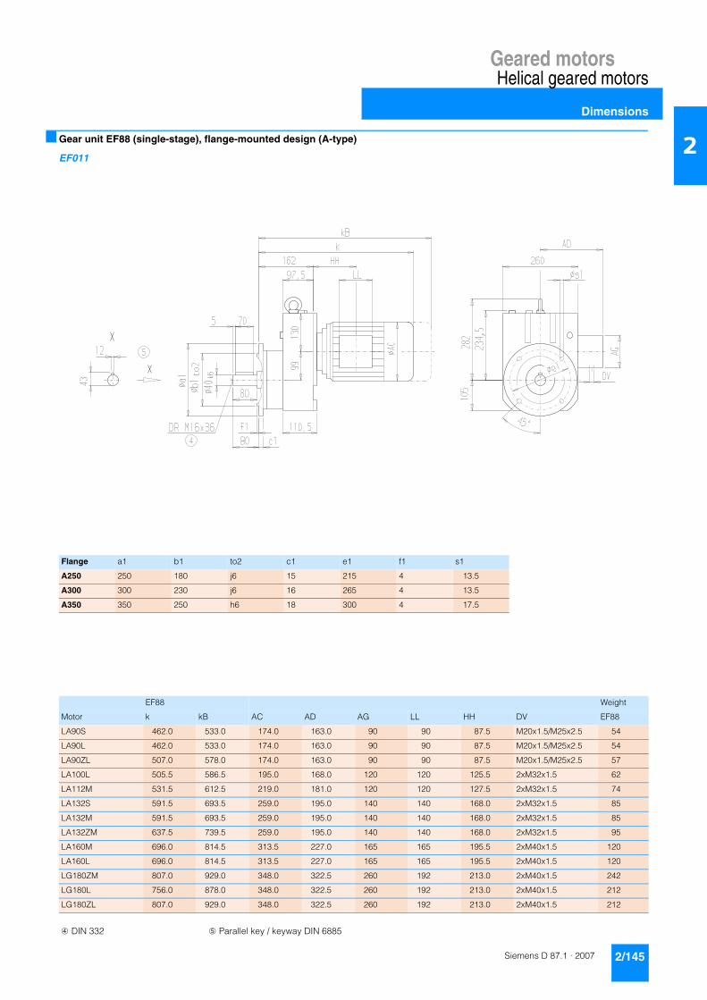
Geared motorsHelical geared motors
Dimensions
2/145Siemens D 87.1 · 2007
2■ Gear unit EF88 (single-stage), flange-mounted design (A-type)
EF011
Flange a1 b1 to2 c1 e1 f1 s1
A250 250 180 j6 15 215 4 13.5
A300 300 230 j6 16 265 4 13.5
A350 350 250 h6 18 300 4 17.5
EF88 Weight
Motor k kB AC AD AG LL HH DV EF88
LA90S 462.0 533.0 174.0 163.0 90 90 87.5 M20x1.5/M25x2.5 54
LA90L 462.0 533.0 174.0 163.0 90 90 87.5 M20x1.5/M25x2.5 54
LA90ZL 507.0 578.0 174.0 163.0 90 90 87.5 M20x1.5/M25x2.5 57
LA100L 505.5 586.5 195.0 168.0 120 120 125.5 2xM32x1.5 62
LA112M 531.5 612.5 219.0 181.0 120 120 127.5 2xM32x1.5 74
LA132S 591.5 693.5 259.0 195.0 140 140 168.0 2xM32x1.5 85
LA132M 591.5 693.5 259.0 195.0 140 140 168.0 2xM32x1.5 85
LA132ZM 637.5 739.5 259.0 195.0 140 140 168.0 2xM32x1.5 95
LA160M 696.0 814.5 313.5 227.0 165 165 195.5 2xM40x1.5 120
LA160L 696.0 814.5 313.5 227.0 165 165 195.5 2xM40x1.5 120
LG180ZM 807.0 929.0 348.0 322.5 260 192 213.0 2xM40x1.5 242
LG180L 756.0 878.0 348.0 322.5 260 192 213.0 2xM40x1.5 212
LG180ZL 807.0 929.0 348.0 322.5 260 192 213.0 2xM40x1.5 212
➃ DIN 332 ➄ Parallel key / keyway DIN 6885

Geared motorsHelical geared motors
Dimensions
2/146 Siemens D 87.1 · 2007
2 ■ Gear unit EZ88 (single-stage), housing-flange-mounted design (C-type)
EZ011
EZ88 Weight
Motor k kB AC AD AG LL HH DV EZ88
LA90S 462.0 533.0 174.0 163.0 90 90 87.5 M20x1.5/M25x2.5 47
LA90L 462.0 533.0 174.0 163.0 90 90 87.5 M20x1.5/M25x2.5 47
LA90ZL 507.0 578.0 174.0 163.0 90 90 87.5 M20x1.5/M25x2.5 50
LA100L 505.5 586.5 195.0 168.0 120 120 125.5 2xM32x1.5 55
LA112M 531.5 612.5 219.0 181.0 120 120 127.5 2xM32x1.5 67
LA132S 591.5 693.5 259.0 195.0 140 140 168.0 2xM32x1.5 79
LA132M 591.5 693.5 259.0 195.0 140 140 168.0 2xM32x1.5 79
LA132ZM 637.5 739.5 259.0 195.0 140 140 168.0 2xM32x1.5 88
LA160M 696.0 814.5 313.5 227.0 165 165 195.5 2xM40x1.5 114
LA160L 696.0 814.5 313.5 227.0 165 165 195.5 2xM40x1.5 114
LG180ZM 807.0 929.0 348.0 322.5 260 192 213.0 2xM40x1.5 236
LG180L 756.0 878.0 348.0 322.5 260 192 213.0 2xM40x1.5 206
LG180ZL 807.0 929.0 348.0 322.5 260 192 213.0 2xM40x1.5 236
➃ DIN 332 ➄ Parallel key / keyway DIN 6885

Geared motorsHelical geared motors
Dimensions
2/147Siemens D 87.1 · 2007
2■ Gear unit E108 (single-stage), foot-mounted design
E011
E108 Weight
Motor k kB AC AD AG LL HH DV E108
LA90S 474.5 545.5 174.0 163.0 90 90 76.0 M20x1.5/M25x2.5 74
LA90L 474.5 545.5 174.0 163.0 90 90 76.0 M20x1.5/M25x2.5 74
LA90ZL 519.5 590.5 174.0 163.0 90 90 76.0 M20x1.5/M25x2.5 77
LA100L 517.5 598.5 195.0 168.0 120 120 113.5 2xM32x1.5 82
LA112M 544.0 625.0 219.0 181.0 120 120 116.0 2xM32x1.5 94
LA132S 603.0 705.0 259.0 195.0 140 140 155.5 2xM32x1.5 105
LA132M 603.0 705.0 259.0 195.0 140 140 155.5 2xM32x1.5 105
LA132ZM 649.0 751.0 259.0 195.0 140 140 155.5 2xM32x1.5 114
LA160M 708.5 827.0 313.5 227.0 165 165 184.0 2xM40x1.5 139
LA160L 708.5 827.0 313.5 227.0 165 165 184.0 2xM40x1.5 139
LG180ZM 816.0 938.0 348.0 322.5 260 192 198.0 2xM40x1.5 266
LG180L 765.0 887.0 348.0 322.5 260 192 198.0 2xM40x1.5 236
LG180ZL 816.0 938.0 348.0 322.5 260 192 198.0 2xM40x1.5 266
LG200L 821.0 947.0 385.0 301.0 260 192 228.0 2xM50x1.5 316
LG225S* 1083.0 AA 439.0 325.0 260 192 197.0 2xM50x1.5 472
LG225M* 1083.0 AA 439.0 325.0 260 192 197.0 2xM50x1.5 460
LG225ZM* 1143.0 AA 439.0 325.0 260 192 197.0 2xM50x1.5 518
➃ DIN 332 ➄ Parallel key / keyway DIN 6885 * Incl. adapter AA On request

Geared motorsHelical geared motors
Dimensions
2/148 Siemens D 87.1 · 2007
2 ■ Gear unit EF108 (single-stage), flange-mounted design (A-type)
EF011
Flange a1 b1 to2 c1 e1 f1 s1
A300 300 230 j6 16 265 4 13.5
A350 350 250 h6 18 300 5 17.5
A450 450 350 h6 22 400 5 17.5
EF108 Weight
Motor k kB AC AD AG LL HH DV EF108
LA90S 474.5 545.5 174.0 163.0 90 90 76.0 M20x1.5/M25x2.5 84
LA90L 474.5 545.5 174.0 163.0 90 90 76.0 M20x1.5/M25x2.5 84
LA90ZL 519.5 590.5 174.0 163.0 90 90 76.0 M20x1.5/M25x2.5 87
LA100L 517.5 598.5 195.0 168.0 120 120 113.5 2xM32x1.5 92
LA112M 544.0 625.0 219.0 181.0 120 120 116.0 2xM32x1.5 104
LA132S 603.0 705.0 259.0 195.0 140 140 155.5 2xM32x1.5 114
LA132M 603.0 705.0 259.0 195.0 140 140 155.5 2xM32x1.5 114
LA132ZM 649.0 751.0 259.0 195.0 140 140 155.5 2xM32x1.5 123
LA160M 708.5 827.0 313.5 227.0 165 165 184.0 2xM40x1.5 149
LA160L 708.5 827.0 313.5 227.0 165 165 184.0 2xM40x1.5 149
LG180ZM 816.0 938.0 348.0 322.5 260 192 198.0 2xM40x1.5 275
LG180L 765.0 887.0 348.0 322.5 260 192 198.0 2xM40x1.5 245
LG180ZL 816.0 938.0 348.0 322.5 260 192 198.0 2xM40x1.5 275
LG200L 821.0 947.0 385.0 301.0 260 192 228.0 2xM50x1.5 325
LG225S* 1083.0 AA 439.0 325.0 260 192 197.0 2xM50x1.5 481
LG225M* 1083.0 AA 439.0 325.0 260 192 197.0 2xM50x1.5 469
LG225ZM* 1143.0 AA 439.0 325.0 260 192 197.0 2xM50x1.5 527
➃ DIN 332 ➄ Parallel key / keyway DIN 6885 * Incl. adapter AA On request
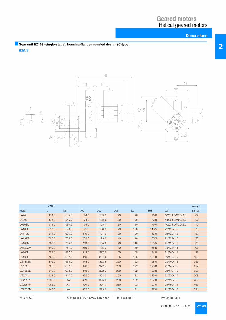
Geared motorsHelical geared motors
Dimensions
2/149Siemens D 87.1 · 2007
2■ Gear unit EZ108 (single-stage), housing-flange-mounted design (C-type)
EZ011
EZ108 Weight
Motor k kB AC AD AG LL HH DV EZ108
LA90S 474.5 545.5 174.0 163.0 90 90 76.0 M20x1.5/M25x2.5 67
LA90L 474.5 545.5 174.0 163.0 90 90 76.0 M20x1.5/M25x2.5 67
LA90ZL 519.5 590.5 174.0 163.0 90 90 76.0 M20x1.5/M25x2.5 70
LA100L 517.5 598.5 195.0 168.0 120 120 113.5 2xM32x1.5 75
LA112M 544.0 625.0 219.0 181.0 120 120 116.0 2xM32x1.5 87
LA132S 603.0 705.0 259.0 195.0 140 140 155.5 2xM32x1.5 98
LA132M 603.0 705.0 259.0 195.0 140 140 155.5 2xM32x1.5 98
LA132ZM 649.0 751.0 259.0 195.0 140 140 155.5 2xM32x1.5 107
LA160M 708.5 827.0 313.5 227.0 165 165 184.0 2xM40x1.5 132
LA160L 708.5 827.0 313.5 227.0 165 165 184.0 2xM40x1.5 132
LG180ZM 816.0 938.0 348.0 322.5 260 192 198.0 2xM40x1.5 259
LG180L 765.0 887.0 348.0 322.5 260 192 198.0 2xM40x1.5 229
LG180ZL 816.0 938.0 348.0 322.5 260 192 198.0 2xM40x1.5 259
LG200L 821.0 947.0 385.0 301.0 260 192 228.0 2xM50x1.5 309
LG225S* 1083.0 AA 439.0 325.0 260 192 197.0 2xM50x1.5 465
LG225M* 1083.0 AA 439.0 325.0 260 192 197.0 2xM50x1.5 453
LG225ZM* 1143.0 AA 439.0 325.0 260 192 197.0 2xM50x1.5 511
➃ DIN 332 ➄ Parallel key / keyway DIN 6885 * Incl. adapter AA On request

Geared motorsHelical geared motors
Dimensions
2/150 Siemens D 87.1 · 2007
2 ■ Gear unit E128 (single-stage), foot-mounted design
E011
E128 Weight
Motor k kB AC AD AG LL HH DV E128
LA100L 539.0 620.0 195.0 168.0 120 120 104.0 2xM32x1.5 121
LA112M 564.5 645.5 219.0 181.0 120 120 105.5 2xM32x1.5 132
LA132S 623.5 725.5 259.0 195.0 140 140 145.0 2xM32x1.5 142
LA132M 623.5 725.5 259.0 195.0 140 140 145.0 2xM32x1.5 142
LA132ZM 669.5 771.5 259.0 195.0 140 140 145.0 2xM32x1.5 151
LA160M 723.0 841.5 313.5 227.0 165 165 167.5 2xM40x1.5 181
LA160L 723.0 841.5 313.5 227.0 165 165 167.5 2xM40x1.5 181
LG180ZM 833.5 955.5 348.0 322.5 260 192 184.5 2xM40x1.5 302
LG180L 782.5 904.5 348.0 322.5 260 192 184.5 2xM40x1.5 272
LG180ZL 833.5 955.5 348.0 322.5 260 192 184.5 2xM40x1.5 302
LG200L 838.5 964.5 385.0 301.0 260 192 214.5 2xM50x1.5 352
LG225S 911.0 AA 439.0 325.0 260 192 250.0 2xM50x1.5 428
LG225M 911.0 AA 439.0 325.0 260 192 250.0 2xM50x1.5 416
LG225ZM 971.0 AA 439.0 325.0 260 192 250.0 2xM50x1.5 474
LG250M* 1200.0 AA 489.0 392.0 300 236 238.0 2xM63x1.5 596
LG250ZM* 1270.0 AA 489.0 392.0 300 236 238.0 2xM63x1.5 699
➃ DIN 332 ➄ Parallel key / keyway DIN 6885 * Incl. adapter AA On request

Geared motorsHelical geared motors
Dimensions
2/151Siemens D 87.1 · 2007
2■ Gear unit EF128 (single-stage), flange-mounted design (A-type)
EF011
Flange a1 b1 to2 c1 e1 f1 s1
A350 350 250 h6 18 300 5 17.5
A450 450 350 h6 20 400 5 17.5
EF128 Weight
Motor k kB AC AD AG LL HH DV EF128
LA100L 539.0 620.0 195.0 168.0 120 120 104.0 2xM32x1.5 125
LA112M 564.5 645.5 219.0 181.0 120 120 105.5 2xM32x1.5 137
LA132S 623.5 725.5 259.0 195.0 140 140 145.0 2xM32x1.5 146
LA132M 623.5 725.5 259.0 195.0 140 140 145.0 2xM32x1.5 146
LA132ZM 669.5 771.5 259.0 195.0 140 140 145.0 2xM32x1.5 155
LA160M 723.0 841.5 313.5 227.0 165 165 167.5 2xM40x1.5 185
LA160L 723.0 841.5 313.5 227.0 165 165 167.5 2xM40x1.5 185
LG180ZM 833.5 955.5 348.0 322.5 260 192 184.5 2xM40x1.5 306
LG180L 782.5 904.5 348.0 322.5 260 192 184.5 2xM40x1.5 276
LG180ZL 833.5 955.5 348.0 322.5 260 192 184.5 2xM40x1.5 306
LG200L 838.5 964.5 385.0 301.0 260 192 214.5 2xM50x1.5 356
LG225S 911.0 AA 439.0 325.0 260 192 250.0 2xM50x1.5 432
LG225M 911.0 AA 439.0 325.0 260 192 250.0 2xM50x1.5 420
LG225ZM 971.0 AA 439.0 325.0 260 192 250.0 2xM50x1.5 478
LG250M* 1200.0 AA 489.0 392.0 300 236 238.0 2xM63x1.5 600
LG250ZM* 1270.0 AA 489.0 392.0 300 236 238.0 2xM63x1.5 703
➃ DIN 332 ➄ Parallel key / keyway DIN 6885 * Incl. adapter AA On request

Geared motorsHelical geared motors
Dimensions
2/152 Siemens D 87.1 · 2007
2 ■ Gear unit EZ128 (single-stage), housing-flange-mounted design (C-type)
EZ011
EZ128 Weight
Motor k kB AC AD AG LL HH DV EZ128
LA100L 539.0 620.0 195.0 168.0 120 120 104.0 2xM32x1.5 108
LA112M 564.5 645.5 219.0 181.0 120 120 105.5 2xM32x1.5 119
LA132S 623.5 725.5 259.0 195.0 140 140 145.0 2xM32x1.5 129
LA132M 623.5 725.5 259.0 195.0 140 140 145.0 2xM32x1.5 129
LA132ZM 669.5 771.5 259.0 195.0 140 140 145.0 2xM32x1.5 138
LA160M 723.0 841.5 313.5 227.0 165 165 167.5 2xM40x1.5 168
LA160L 723.0 841.5 313.5 227.0 165 165 167.5 2xM40x1.5 168
LG180ZM 833.5 955.5 348.0 322.5 260 192 184.5 2xM40x1.5 289
LG180L 782.5 904.5 348.0 322.5 260 192 184.5 2xM40x1.5 259
LG180ZL 833.5 955.5 348.0 322.5 260 192 184.5 2xM40x1.5 289
LG200L 838.5 964.5 385.0 301.0 260 192 214.5 2xM50x1.5 339
LG225S 911.0 AA 439.0 325.0 260 192 250.0 2xM50x1.5 415
LG225M 911.0 AA 439.0 325.0 260 192 250.0 2xM50x1.5 403
LG225ZM 971.0 AA 439.0 325.0 260 192 250.0 2xM50x1.5 461
LG250M* 1200.0 AA 489.0 392.0 300 236 238.0 2xM63x1.5 583
LG250ZM* 1270.0 AA 489.0 392.0 300 236 238.0 2xM63x1.5 686
➃ DIN 332 ➄ Parallel key / keyway DIN 6885 ➆ For note, see page 2/191* Incl. adapter AA On request

Geared motorsHelical geared motors
Dimensions
2/153Siemens D 87.1 · 2007
2■ Gear unit E148 (single-stage), foot-mounted design
E011
E148 Weight
Motor k kB AC AD AG LL HH DV E148
LA132S 636.5 738.5 259.0 195.0 140 140 137.0 2xM32x1.5 169
LA132M 636.5 738.5 259.0 195.0 140 140 137.0 2xM32x1.5 169
LA132ZM 682.5 784.5 259.0 195.0 140 140 137.0 2xM32x1.5 178
LA160M 736.5 855.0 313.5 227.0 165 165 160.0 2xM40x1.5 203
LA160L 736.5 855.0 313.5 227.0 165 165 160.0 2xM40x1.5 203
LG180ZM 847.0 969.0 348.0 322.5 260 192 177.0 2xM40x1.5 328
LG180L 796.0 918.0 348.0 322.5 260 192 177.0 2xM40x1.5 298
LG180ZL 847.0 969.0 348.0 322.5 260 192 177.0 2xM40x1.5 328
LG200L 852.0 978.0 395.0 301.0 260 192 207.0 2xM50x1.5 378
LG225S 924.5 AA 439.0 325.0 260 192 242.5 2xM50x1.5 452
LG225M 924.5 AA 439.0 325.0 260 192 242.5 2xM50x1.5 440
LG225ZM 984.5 AA 439.0 325.0 260 192 242.5 2xM50x1.5 498
LG250M 1019.5 AA 489.0 392.0 300 236 278.0 2xM63x1.5 542
LG250ZM 1089.5 AA 489.0 392.0 300 236 278.0 2xM63x1.5 645
LG280S* 1296.0 AA 540.0 432.0 300 236 253.0 2xM63x1.5 774
LG280M* 1296.0 AA 540.0 432.0 300 236 253.0 2xM63x1.5 785
LG280ZM* 1406.0 AA 540.0 432.0 300 236 253.0 2xM63x1.5 874
➃ DIN 332 ➄ Parallel key / keyway DIN 6885 * Incl. adapter AA On request

Geared motorsHelical geared motors
Dimensions
2/154 Siemens D 87.1 · 2007
2 ■ Gear unit EF148 (single-stage), flange-mounted design (A-type)
EF011
Flange a1 b1 to2 c1 e1 f1 s1
A350 350 250 h6 18 300 5 17.5
A450 450 350 h6 22 400 5 17.5
A550 550 450 h6 25 500 5 17.5
EF148 Weight
Motor k kB AC AD AG LL HH DV EF148
LA132S 636.5 738.5 259.0 195.0 140 140 137.0 2xM32x1.5 180
LA132M 636.5 738.5 259.0 195.0 140 140 137.0 2xM32x1.5 180
LA132ZM 682.5 784.5 259.0 195.0 140 140 137.0 2xM32x1.5 190
LA160M 736.5 855.0 313.5 227.0 165 165 160.0 2xM40x1.5 214
LA160L 736.5 855.0 313.5 227.0 165 165 160.0 2xM40x1.5 214
LG180ZM 847.0 969.0 348.0 322.5 260 192 177.0 2xM40x1.5 340
LG180L 796.0 918.0 348.0 322.5 260 192 177.0 2xM40x1.5 310
LG180ZL 847.0 969.0 348.0 322.5 260 192 177.0 2xM40x1.5 340
LG200L 852.0 978.0 385.0 301.0 260 192 207.0 2xM50x1.5 390
LG225S 924.5 AA 439.0 325.0 260 192 242.5 2xM50x1.5 464
LG225M 924.5 AA 439.0 325.0 260 192 242.5 2xM50x1.5 452
LG225ZM 984.5 AA 439.0 325.0 260 192 242.5 2xM50x1.5 510
LG250M 1019.5 AA 489.0 392.0 300 236 278.0 2xM63x1.5 554
LG250ZM 1089.5 AA 489.0 392.0 300 236 278.0 2xM63x1.5 657
LG280S* 1296.0 AA 540.0 432.0 300 236 253.0 2xM63x1.5 786
LG280M* 1296.0 AA 540.0 432.0 300 236 253.0 2xM63x1.5 797
LG280ZM* 1406.0 AA 540.0 432.0 300 236 253.0 2xM63x1.5 886
➃ DIN 332 ➄ Parallel key / keyway DIN 6885 * Incl. adapter AA On request

Geared motorsHelical geared motors
Dimensions
2/155Siemens D 87.1 · 2007
2■ Gear unit EZ148 (single-stage), housing-flange-mounted design (C-type)
EZ011
EZ148 Weight
Motor k kB AC AD AG LL HH DV EZ148
LA132S 636.5 738.5 259.0 195.0 140 140 137.0 2xM32x1.5 154
LA132M 636.5 738.5 259.0 195.0 140 140 137.0 2xM32x1.5 154
LA132ZM 682.5 784.5 259.0 195.0 140 140 137.0 2xM32x1.5 163
LA160M 736.5 855.0 313.5 227.0 165 165 160.0 2xM40x1.5 188
LA160L 736.5 855.0 313.5 227.0 165 165 160.0 2xM40x1.5 188
LG180ZM 847.0 969.0 348.0 322.5 260 192 177.0 2xM40x1.5 313
LG180L 796.0 918.0 348.0 322.5 260 192 177.0 2xM40x1.5 283
LG180ZL 847.0 969.0 348.0 322.5 260 192 177.0 2xM40x1.5 313
LG200L 852.0 978.0 385.0 301.0 260 192 207.0 2xM50x1.5 363
LG225S 924.5 AA 439.0 325.0 260 192 242.5 2xM50x1.5 437
LG225M 924.5 AA 439.0 325.0 260 192 242.5 2xM50x1.5 425
LG225ZM 984.5 AA 439.0 325.0 260 192 242.5 2xM50x1.5 483
LG250M 1019.5 AA 489.0 392.0 300 236 278.0 2xM63x1.5 527
LG250ZM 1089.5 AA 489.0 392.0 300 236 278.0 2xM63x1.5 630
LG280S* 1296.0 AA 540.0 432.0 300 236 253.0 2xM63x1.5 759
LG280M* 1296.0 AA 540.0 432.0 300 236 253.0 2xM63x1.5 770
LG280ZM* 1406.0 AA 540.0 432.0 300 236 253.0 2xM63x1.5 859
➃ DIN 332 ➄ Parallel key / keyway DIN 6885 ➆ For note, see page 2/191* Incl. adapter AA On request

Geared motorsHelical geared motors
Dimensions
2/156 Siemens D 87.1 · 2007
2 ■ Gear unit D/Z18 (two-/three-stage), foot-mounted design
DZ011
Z18 D18 Weight
Motor k kB k kB AC AD AG LL HH DV Z18 D18
LA71 327 382 327 382 139 146 90 90 40.5 M20x1.5/M25x2.5 8 8
LA71Z 346 401 346 401 139 146 90 90 40.5 M20x1.5/M25x2.5 8 8
➃ DIN 332 ➄ Parallel key / keyway DIN 6885

Geared motorsHelical geared motors
Dimensions
2/157Siemens D 87.1 · 2007
2■ Gear unit DF/ZF18 (two-/three-stage), flange-mounted design (A-type)
DZF011
Flange a1 b1 to2 c1 e1 f1 q1 s1 i2
A120 120 80 j6 8 100 3.0 28 6.6 40
A140 140 95 j6 9 115 3.0 27 9.0 40
A160 160 110 j6 9 130 3.5 27 9.0 40
ZF18 DF18 Weight
Motor k kB k kB AC AD AG LL HH DV ZF18 DF18
LA71 335 390 335 390 139 146 90 90 40.5 M20x1.5/M25x2.5 8 9
LA71Z 354 409 354 409 139 146 90 90 40.5 M20x1.5/M25x2.5 8 9
➃ DIN 332 ➄ Parallel key / keyway DIN 6885

Geared motorsHelical geared motors
Dimensions
2/158 Siemens D 87.1 · 2007
2 ■ Gear unit D/Z28 (two-/three-stage), foot-mounted design
DZ011
Z28 D28 Weight
Motor k kB k kB AC AD AG LL HH DV Z28 D28
LA71 337.5 392.5 337.5 392.5 139 146 90 90 58.5 M20x1.5/M25x2.5 9 9
LA71Z 356.5 411.5 356.5 411.5 139 146 90 90 58.5 M20x1.5/M25x2.5 9 9
LA90S 434.5 505.5 434.5 505.5 174 185 90 90 87.0 M20x1.5/M25x2.5 18 19
LA90L 434.5 505.5 434.5 505.5 174 185 90 90 87.0 M20x1.5/M25x2.5 18 19
LA90ZL 479.5 550.5 479.5 550.5 174 185 90 90 87.0 M20x1.5/M25x2.5 21 22
LA100L 516.5 597.5 – – 195 168 120 120 163.5 2xM32x1.5 28 –
➃ DIN 332 ➄ Parallel key / keyway DIN 6885

Geared motorsHelical geared motors
Dimensions
2/159Siemens D 87.1 · 2007
2■ Gear unit DF/ZF28 (two-/three-stage), flange-mounted design (A-type)
DZF011
Flange a1 b1 to2 c1 e1 f1 q1 s1 i2
A120 120 80 j6 8 100 3.0 28 6.6 50
A140 140 95 j6 9 115 3.0 27 9.0 50
A160 160 110 j6 9 130 3.5 27 9.0 50
ZF28 DF28 Weight
Motor k kB k kB AC AD AG LL HH DV ZF28 DF28
LA71 343.5 398.5 337.5 392.5 139 146 90 90 58.5 M20x1.5/M25x2.5 9 9
LA71Z 362.5 417.5 356.5 411.5 139 146 90 90 58.5 M20x1.5/M25x2.5 9 9
LA90S 440.5 511.5 440.5 511.5 174 185 90 90 87.0 M20x1.5/M25x2.5 18 19
LA90L 440.5 511.5 440.5 511.5 174 185 90 90 87.0 M20x1.5/M25x2.5 18 19
LA90ZL 485.5 556.5 485.5 556.5 174 185 90 90 87.0 M20x1.5/M25x2.5 21 22
LA100L 522.5 603.5 – – 195 168 120 120 163.5 2xM32x1.5 28 –
➃ DIN 332 ➄ Parallel key / keyway DIN 6885

Geared motorsHelical geared motors
Dimensions
2/160 Siemens D 87.1 · 2007
2 ■ Gear unit D/Z38 (two-/three-stage), foot-mounted design
DZ011
d to1 l l4 l3 t u i DR
30* k6 60 7 50 33 8 85M10x22
25 k6 50 7 40 28 8 75
*) Preferred series
Z38 D38 Z38 D38 Weight
Motor k kB k kB AC AD AG LL HH HH DV Z38 D38
LA71 398.5 453.5 413.5 468.5 139.0 146 90 90 114.5 129.5 M20x1.5/M25x2.5 16 17
LA71Z 417.5 472.5 432.5 487.5 139.0 146 90 90 114.5 129.5 M20x1.5/M25x2.5 16 17
LA80 435.5 499.0 450.5 514.0 156.5 155 90 90 114.0 129.0 M20x1.5/M25x2.5 21 22
LA90S 466.5 537.5 481.5 552.5 174.0 163 90 90 114.0 129.0 M20x1.5/M25x2.5 26 27
LA90L 466.5 537.5 481.5 552.5 174.0 163 90 90 114.0 129.0 M20x1.5/M25x2.5 26 27
LA90ZL 511.5 582.5 526.5 597.5 174.0 163 90 90 114.0 129.0 M20x1.5/M25x2.5 29 30
LA100L 512.5 593.5 – – 195.0 168 120 120 154.5 – 2xM32x1.5 35 –
LA112M 542.0 623.0 – – 219.0 181 120 120 160.0 – 2xM32x1.5 45 –
➃ DIN 332 ➄ Parallel key / keyway DIN 6885

Geared motorsHelical geared motors
Dimensions
2/161Siemens D 87.1 · 2007
2■ Gear unit DF/ZF38 (two-/three-stage), flange-mounted design (A-type)
DZF011
Flange a1 b1 to2 c1 e1 f1 q1 s1 d to1 l l4 l3 t u i2 DR
A120 120 80 j6 8 100 3.0 23 6.8 30 k6 60 7 50 33 8 60M10x22
25 k6 50 7 40 28 8 50
A140 140 95 j6 7 115 3.0 26 9.0 30 k6 60 7 50 33 8 60M10x22
25 k6 50 7 40 28 8 50
A160 160 110 j6 10 130 3.5 26 9.0 30 k6 60 7 50 33 8 60M10x22
25 k6 50 7 40 28 8 50
A200 1) 200 130 j6 12 165 3.5 24 11.0 30 k6 60 7 50 33 8 60M10x22
25 k6 50 7 40 28 8 50
A250 250 180 j6 15 215 4.0 21 13.5 30 k6 60 7 50 33 8 60M10x22
25 k6 50 7 40 28 8 50
ZF38 DF38 ZF38 DF38 Weight
Motor k kB k kB AC AD AG LL HH HH DV ZF38 DF38
LA71 398.5 453.5 413.5 468.5 139.0 146 90 90 114.5 129.5 M20x1.5/M25x2.5 17 18
LA71Z 417.5 472.5 432.5 487.5 139.0 146 90 90 114.5 129.5 M20x1.5/M25x2.5 17 18
LA80 435.5 499.0 450.5 514.0 156.5 155 90 90 114.0 129.0 M20x1.5/M25x2.5 22 22
LA90S 466.5 537.5 481.5 552.5 174.0 163 90 90 114.0 129.0 M20x1.5/M25x2.5 26 27
LA90L 466.5 537.5 481.5 552.5 174.0 163 90 90 114.0 129.0 M20x1.5/M25x2.5 26 27
LA90ZL 511.5 582.5 526.5 597.5 174.0 163 90 90 114.0 129.0 M20x1.5/M25x2.5 29 30
LA100L 512.5 593.5 – – 195.0 168 120 120 154.5 – 2xM32x1.5 35 –
LA112M 542.0 623.0 – – 219.0 181 120 120 160.0 – 2xM32x1.5 46 –
➃ DIN 332 ➄ Parallel key / keyway DIN 6885 1) The A200 flange is connected to the machine using stud bolts.
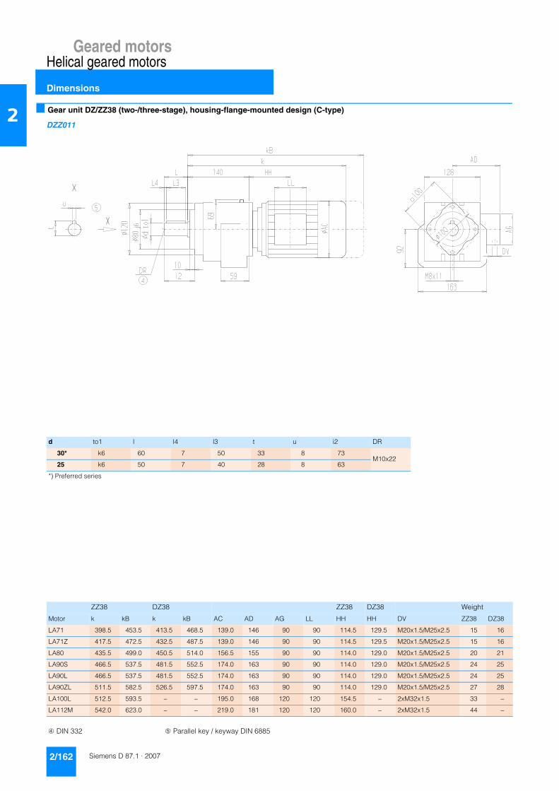
Geared motorsHelical geared motors
Dimensions
2/162 Siemens D 87.1 · 2007
2 ■ Gear unit DZ/ZZ38 (two-/three-stage), housing-flange-mounted design (C-type)
DZZ011
d to1 l l4 l3 t u i2 DR
30* k6 60 7 50 33 8 73M10x22
25 k6 50 7 40 28 8 63
*) Preferred series
ZZ38 DZ38 ZZ38 DZ38 Weight
Motor k kB k kB AC AD AG LL HH HH DV ZZ38 DZ38
LA71 398.5 453.5 413.5 468.5 139.0 146 90 90 114.5 129.5 M20x1.5/M25x2.5 15 16
LA71Z 417.5 472.5 432.5 487.5 139.0 146 90 90 114.5 129.5 M20x1.5/M25x2.5 15 16
LA80 435.5 499.0 450.5 514.0 156.5 155 90 90 114.0 129.0 M20x1.5/M25x2.5 20 21
LA90S 466.5 537.5 481.5 552.5 174.0 163 90 90 114.0 129.0 M20x1.5/M25x2.5 24 25
LA90L 466.5 537.5 481.5 552.5 174.0 163 90 90 114.0 129.0 M20x1.5/M25x2.5 24 25
LA90ZL 511.5 582.5 526.5 597.5 174.0 163 90 90 114.0 129.0 M20x1.5/M25x2.5 27 28
LA100L 512.5 593.5 – – 195.0 168 120 120 154.5 – 2xM32x1.5 33 –
LA112M 542.0 623.0 – – 219.0 181 120 120 160.0 – 2xM32x1.5 44 –
➃ DIN 332 ➄ Parallel key / keyway DIN 6885

Geared motorsHelical geared motors
Dimensions
2/163Siemens D 87.1 · 2007
2■ Gear unit D/Z48 (two-/three-stage), foot-mounted design
DZ011
d to1 l l4 l3 t u i DR
40* k6 80 5 70 43 12 110 M16x36
30 k6 60 7 50 33 8 90 M10x22
*) Preferred series
Z48 D48 Z48 D48 Weight
Motor k kB k kB AC AD AG LL HH HH DV Z48 D48
LA71 426 481.0 443 498.0 139.0 146 90 90 109.0 126.0 M20x1.5/M25x2.5 26 27
LA71Z 445 500.0 462 517.0 139.0 146 90 90 109.0 126.0 M20x1.5/M25x2.5 26 27
LA80 463 526.5 480 543.5 156.5 155 90 90 108.5 125.5 M20x1.5/M25x2.5 31 32
LA90S 494 565.0 511 582.0 174.0 163 90 90 108.5 125.5 M20x1.5/M25x2.5 35 36
LA90L 494 565.0 511 582.0 174.0 163 90 90 108.5 125.5 M20x1.5/M25x2.5 35 36
LA90ZL 539 610.0 556 627.0 174.0 163 90 90 108.5 125.5 M20x1.5/M25x2.5 38 39
LA100L 540 621.0 557 638.0 195.0 168 120 120 149.0 166.0 2xM32x1.5 44 45
LA112M 569 650.0 – – 219.0 181 120 120 154.0 – 2xM32x1.5 56 –
LA132S 631 733.0 – – 259.0 195 140 140 196.5 – 2xM32x1.5 66 –
LA132M 631 733.0 – – 259.0 195 140 140 196.5 – 2xM32x1.5 66 –
LA132ZM 677 779.0 – – 259.0 195 140 140 196.5 – 2xM32x1.5 75 –
➃ DIN 332 ➄ Parallel key / keyway DIN 6885

Geared motorsHelical geared motors
Dimensions
2/164 Siemens D 87.1 · 2007
2 ■ Gear unit DF/ZF48 (two-/three-stage), flange-mounted design (A-type)
DZF011
Flange a1 b1 to2 c1 e1 f1 q1 s1 d to1 l l4 l3 t u i2 DR
A200 200 130 j6 12 165 3.5 29 11.0 40 k6 80 5 70 43 12 80 M16x36
30 k6 60 7 50 33 8 60 M10x22
A250 1) 250 180 j6 15 215 4.0 26 13.5 40 k6 80 5 70 43 12 80 M16x36
30 k6 60 7 50 33 8 60 M10x22
A300 300 230 j6 15 265 4.0 26 13.5 40 k6 80 5 70 43 12 80 M16x36
30 k6 60 7 50 33 8 60 M10x22
ZF48 DF48 ZF48 DF48 Weight
Motor k kB k kB AC AD AG LL HH HH DV ZF48 DF48
LA71 426 481.0 443 498.0 139.0 146 90 90 109.0 126.0 M20x1.5/M25x2.5 27 28
LA71Z 445 500.0 462 517.0 139.0 146 90 90 109.0 126.0 M20x1.5/M25x2.5 27 28
LA80 463 526.5 480 543.5 156.5 155 90 90 108.5 125.5 M20x1.5/M25x2.5 32 33
LA90S 494 565.0 511 582.0 174.0 163 90 90 108.5 125.5 M20x1.5/M25x2.5 37 38
LA90L 494 565.0 511 582.0 174.0 163 90 90 108.5 125.5 M20x1.5/M25x2.5 37 38
LA90ZL 539 610.0 556 627.0 174.0 163 90 90 108.5 125.5 M20x1.5/M25x2.5 40 40
LA100L 540 621.0 557 638.0 195.0 168 120 120 149.0 166.0 2xM32x1.5 46 47
LA112M 569 650.0 – – 219.0 181 120 120 154.0 – 2xM32x1.5 57 –
LA132S 631 733.0 – – 259.0 195 140 140 196.5 – 2xM32x1.5 67 –
LA132M 631 733.0 – – 259.0 195 140 140 196.5 – 2xM32x1.5 67 –
LA132ZM 677 779.0 – – 259.0 195 140 140 196.5 – 2xM32x1.5 76 –
➃ DIN 332 ➄ Parallel key / keyway DIN 6885 1) The A250 flange is connected to the machine using stud bolts.

Geared motorsHelical geared motors
Dimensions
2/165Siemens D 87.1 · 2007
2■ Gear unit DZ/ZZ48 (two-/three-stage), housing-flange-mounted design (C-type)
DZZ011
d to1 l l4 l3 t u i2 DR
40* k6 80 5 70 43 12 97 M16x36
30 k6 60 7 50 33 8 77 M10x22
*) Preferred series
ZZ48 DZ48 ZZ48 DZ48 Weight
Motor k kB k kB AC AD AG LL HH HH DV ZZ48 DZ48
LA71 426 481.0 443 498.0 139.0 146 90 90 109.0 126.0 M20x1.5/M25x2.5 24 25
LA71Z 445 500.0 462 517.0 139.0 146 90 90 109.0 126.0 M20x1.5/M25x2.5 24 25
LA80 463 526.5 480 543.5 156.5 155 90 90 108.5 125.5 M20x1.5/M25x2.5 29 30
LA90S 494 565.0 511 582.0 174.0 163 90 90 108.5 125.5 M20x1.5/M25x2.5 33 34
LA90L 494 565.0 511 582.0 174.0 163 90 90 108.5 125.5 M20x1.5/M25x2.5 33 34
LA90ZL 539 610.0 556 627.0 174.0 163 90 90 108.5 125.5 M20x1.5/M25x2.5 36 37
LA100L 540 621.0 557 638.0 195.0 168 120 120 149.0 166.0 2xM32x1.5 42 43
LA112M 569 650.0 – – 219.0 181 120 120 154.0 – 2xM32x1.5 54 –
LA132S 631 733.0 – – 259.0 195 140 140 196.5 – 2xM32x1.5 64 –
LA132M 631 733.0 – – 259.0 195 140 140 196.5 – 2xM32x1.5 64 –
LA132ZM 677 779.0 – – 259.0 195 140 140 196.5 – 2xM32x1.5 73 –
➃ DIN 332 ➄ Parallel key / keyway DIN 6885

Geared motorsHelical geared motors
Dimensions
2/166 Siemens D 87.1 · 2007
2 ■ Gear unit D/Z68 (two-/three-stage), foot-mounted design
DZ011
d to1 l l4 l3 t u i DR
50* k6 100 10 80 53.5 14 135M16x36
40 k6 80 5 70 43.0 12 115
*) Preferred series
Z68 D68 Z68 D68 Weight
Motor k kB k kB AC AD AG LL HH HH DV Z68 D68
LA71 456.0 511.0 474.5 529.5 139.0 146 90 90 103.0 121.5 M20x1.5/M25x2.5 43 45
LA71Z 475.0 530.0 493.5 548.5 139.0 146 90 90 103.0 121.5 M20x1.5/M25x2.5 43 45
LA80 493.0 556.5 511.5 575.0 156.5 155 90 90 102.5 121.0 M20x1.5/M25x2.5 48 50
LA90S 524.0 595.0 542.5 613.5 174.0 163 90 90 102.5 121.0 M20x1.5/M25x2.5 52 55
LA90L 524.0 595.0 542.5 613.5 174.0 163 90 90 102.5 121.0 M20x1.5/M25x2.5 52 55
LA90ZL 569.0 640.0 587.5 658.5 174.0 163 90 90 102.5 121.0 M20x1.5/M25x2.5 55 57
LA100L 570.0 651.0 588.5 669.5 195.0 168 120 120 143.0 161.5 2xM32x1.5 61 64
LA112M 597.0 678.0 – – 219.0 181 120 120 146.0 – 2xM32x1.5 73 –
LA132S 657.0 759.0 – – 259.0 195 140 140 186.5 – 2xM32x1.5 86 –
LA132M 657.0 759.0 – – 259.0 195 140 140 186.5 – 2xM32x1.5 86 –
LA132ZM 703.0 805.0 – – 259.0 195 140 140 186.5 – 2xM32x1.5 95 –
LA160M 759.5 878.0 – – 313.5 227 165 165 212.0 – 2xM40x1.5 119 –
LA160L 759.5 878.0 – – 313.5 227 165 165 212.0 – 2xM40x1.5 119 –
➃ DIN 332 ➄ Parallel key / keyway DIN 6885

Geared motorsHelical geared motors
Dimensions
2/167Siemens D 87.1 · 2007
2■ Gear unit DF/ZF68 (two-/three-stage), flange-mounted design (A-type)
DZF011
Flange a1 b1 to2 c1 e1 f1 q1 s1 d to1 l l4 l3 t u i2 DR
A250 250 180 j6 15 215 4 40 13.5 50 k6 100 10 80 53.5 14 100M16x36
40 k6 80 5 70 43.0 12 80
A300 300 230 j6 16 265 4 39 13.5 50 k6 100 10 80 53.5 14 100M16x36
40 k6 80 5 70 43.0 12 80
A350 350 250 h6 16 300 4 39 17.5 50 k6 100 10 80 53.5 14 100M16x36
40 k6 80 5 70 43.0 12 80
ZF68 DF68 ZF68 DF68 Weight
Motor k kB k kB AC AD AG LL HH HH DV ZF68 DF68
LA71 456.0 511.0 474.5 529.5 139.0 146 90 90 103.0 121.5 M20x1.5/M25x2.5 45 47
LA71Z 475.0 530.0 493.5 548.5 139.0 146 90 90 103.0 121.5 M20x1.5/M25x2.5 45 47
LA80 493.0 556.5 511.5 575.0 156.5 155 90 90 102.5 121.0 M20x1.5/M25x2.5 49 52
LA90S 524.0 595.0 542.5 613.5 174.0 163 90 90 102.5 121.0 M20x1.5/M25x2.5 54 56
LA90L 524.0 595.0 542.5 613.5 174.0 163 90 90 102.5 121.0 M20x1.5/M25x2.5 54 56
LA90ZL 569.0 640.0 587.5 658.5 174.0 163 90 90 102.5 121.0 M20x1.5/M25x2.5 57 59
LA100L 570.0 651.0 588.5 669.5 195.0 168 120 120 143.0 161.5 2xM32x1.5 63 65
LA112M 597.0 678.0 – – 219.0 181 120 120 146.0 – 2xM32x1.5 75 –
LA132S 657.0 759.0 – – 259.0 195 140 140 186.5 – 2xM32x1.5 88 –
LA132M 657.0 759.0 – – 259.0 195 140 140 186.5 – 2xM32x1.5 88 –
LA132ZM 703.0 805.0 – – 259.0 195 140 140 186.5 – 2xM32x1.5 97 –
LA160M 759.5 878.0 – – 313.5 227 165 165 212.0 – 2xM40x1.5 121 –
LA160L 759.5 878.0 – – 313.5 227 165 165 212.0 – 2xM40x1.5 121 –
➃ DIN 332 ➄ Parallel key / keyway DIN 6885
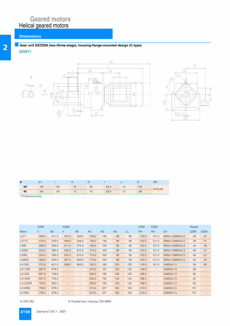
Geared motorsHelical geared motors
Dimensions
2/168 Siemens D 87.1 · 2007
2 ■ Gear unit DZ/ZZ68 (two-/three-stage), housing-flange-mounted design (C-type)
DZZ011
d to1 l l4 l3 t u i2 DR
50* k6 100 10 80 53.5 14 118M16x36
40 k6 80 5 70 43.0 12 98
*) Preferred series
ZZ68 DZ68 ZZ68 DZ68 Weight
Motor k kB k kB AC AD AG LL HH HH DV ZZ68 DZ68
LA71 456.0 511.0 474.5 529.5 139.0 146 90 90 103.0 121.5 M20x1.5/M25x2.5 39 41
LA71Z 475.0 530.0 493.5 548.5 139.0 146 90 90 103.0 121.5 M20x1.5/M25x2.5 39 41
LA80 493.0 556.5 511.5 575.0 156.5 155 90 90 102.5 121.0 M20x1.5/M25x2.5 44 46
LA90S 524.0 595.0 542.5 613.5 174.0 163 90 90 102.5 121.0 M20x1.5/M25x2.5 49 51
LA90L 524.0 595.0 542.5 613.5 174.0 163 90 90 102.5 121.0 M20x1.5/M25x2.5 49 51
LA90ZL 569.0 640.0 587.5 658.5 174.0 163 90 90 102.5 121.0 M20x1.5/M25x2.5 52 54
LA100L 570.0 651.0 588.5 669.5 195.0 168 120 120 143.0 161.5 2xM32x1.5 58 60
LA112M 597.0 678.0 – – 219.0 181 120 120 146.0 – 2xM32x1.5 69 –
LA132S 657.0 759.0 – – 259.0 195 140 140 186.5 – 2xM32x1.5 82 –
LA132M 657.0 759.0 – – 259.0 195 140 140 186.5 – 2xM32x1.5 82 –
LA132ZM 703.0 805.0 – – 259.0 195 140 140 186.5 – 2xM32x1.5 92 –
LA160M 759.5 878.0 – – 313.5 227 165 165 212.0 – 2xM40x1.5 115 –
LA160L 759.5 878.0 – – 313.5 227 165 165 212.0 – 2xM40x1.5 115 –
➃ DIN 332 ➄ Parallel key / keyway DIN 6885

Geared motorsHelical geared motors
Dimensions
2/169Siemens D 87.1 · 2007
2■ Gear unit D/Z88 (two-/three-stage), foot-mounted design
DZ011
d to1 l l4 l3 t u i DR
60* m6 120 10 100 64.0 18 160 M20x42
50 k6 100 10 80 53.5 14 140 M16x36
*) Preferred series
Z88 D88 Z88 D88 Weight
Motor k kB k kB AC AD AG LL HH HH DV Z88 D88
LA71 – – 523.0 578.0 139.0 146.0 90 90 – 113.0 M20x1.5/M25x2.5 – 76
LA71Z – – 542.0 597.0 139.0 146.0 90 90 – 113.0 M20x1.5/M25x2.5 – 76
LA80 – – 560.0 623.5 156.5 155.0 90 90 – 112.5 M20x1.5/M25x2.5 – 81
LA90S 566.0 637.0 591.0 662.0 174.0 163.0 90 90 87.5 112.5 M20x1.5/M25x2.5 85 86
LA90L 566.0 637.0 591.0 662.0 174.0 163.0 90 90 87.5 112.5 M20x1.5/M25x2.5 85 86
LA90ZL 611.0 682.0 636.0 707.0 174.0 163.0 90 90 87.5 112.5 M20x1.5/M25x2.5 88 89
LA100L 609.5 690.5 637.0 718.0 195.0 168.0 120 120 125.5 153.0 2xM32x1.5 93 95
LA112M 635.5 716.5 664.5 745.5 219.0 181.0 120 120 127.5 156.5 2xM32x1.5 106 107
LA132S 695.5 797.5 723.5 825.5 259.0 195.0 140 140 168.0 196.0 2xM32x1.5 117 120
LA132M 695.5 797.5 723.5 825.5 259.0 195.0 140 140 168.0 196.0 2xM32x1.5 117 120
LA132ZM 741.5 843.5 769.5 871.5 259.0 195.0 140 140 168.0 196.0 2xM32x1.5 126 129
LA160M 800.0 918.5 – – 313.5 227.0 165 165 195.5 – 2xM40x1.5 152 –
LA160L 800.0 918.5 – – 313.5 227.0 165 165 195.5 – 2xM40x1.5 152 –
LG180ZM 910.5 1032.5 – – 348.0 322.5 260 192 212.5 – 2xM40x1.5 274 –
LG180L 859.5 981.5 – – 348.0 322.5 260 192 212.5 – 2xM40x1.5 244 –
LG180ZL 910.5 1032.5 – – 348.0 322.5 260 192 212.5 – 2xM40x1.5 274 –
➃ DIN 332 ➄ Parallel key / keyway DIN 6885

Geared motorsHelical geared motors
Dimensions
2/170 Siemens D 87.1 · 2007
2 ■ Gear unit DF/ZF88 (two-/three-stage), flange-mounted design (A-type)
DZF011
Flange a1 b1 to2 c1 e1 f1 q1 s1 d to1 l l4 l3 t u i2 DR
A300 300 230 j6 16 265 4 54 13.5 60 m6 120 10 100 64.0 18 120 M20x42
50 k6 100 10 80 53.5 14 100 M16x36
A350 350 250 h6 18 300 5 52 17.5 60 m6 120 10 100 64.0 18 120 M20x42
50 k6 100 10 80 53.5 14 100 M16x36
A450 450 350 j6 18 400 5 52 17.5 60 m6 120 10 100 64.0 18 120 M20x42
50 k6 100 10 80 53.5 14 100 M16x36
ZF88 DF88 ZF88 DF88 Weight
Motor k kB k kB AC AD AG LL HH HH DV ZF88 DF88
LA71 – – 523.0 578.0 139.0 146.0 90 90 – 113.0 M20x1.5/M25x2.5 – 78
LA71Z – – 542.0 597.0 139.0 146.0 90 90 – 113.0 M20x1.5/M25x2.5 – 78
LA80 – – 560.0 623.5 156.5 155.0 90 90 – 112.5 M20x1.5/M25x2.5 – 83
LA90S 566.0 637.0 591.0 662.0 174.0 163.0 90 90 87.5 112.5 M20x1.5/M25x2.5 87 88
LA90L 566.0 637.0 591.0 662.0 174.0 163.0 90 90 87.5 112.5 M20x1.5/M25x2.5 87 88
LA90ZL 611.0 682.0 636.0 707.0 174.0 163.0 90 90 87.5 112.5 M20x1.5/M25x2.5 90 90
LA100L 609.5 690.5 637.0 718.0 195.0 168.0 120 120 125.5 153.0 2xM32x1.5 95 97
LA112M 635.5 716.5 664.5 745.5 219.0 181.0 120 120 127.5 156.5 2xM32x1.5 108 109
LA132S 695.5 797.5 723.5 825.5 259.0 195.0 140 140 168.0 196.0 2xM32x1.5 119 122
LA132M 695.5 797.5 723.5 825.5 259.0 195.0 140 140 168.0 196.0 2xM32x1.5 119 122
LA132ZM 741.5 843.5 769.5 871.5 259.0 195.0 140 140 168.0 196.0 2xM32x1.5 128 131
LA160M 800.0 918.5 – – 313.5 227.0 165 165 195.5 – 2xM40x1.5 154 –
LA160L 800.0 918.5 – – 313.5 227.0 165 165 195.5 – 2xM40x1.5 154 –
LG180ZM 910.5 1032.5 – – 348.0 322.5 260 192 212.5 – 2xM40x1.5 276 –
LG180L 859.5 981.5 – – 348.0 322.5 260 192 212.5 – 2xM40x1.5 246 –
LG180ZL 910.5 1032.5 – – 348.0 322.5 260 192 212.5 – 2xM40x1.5 276 –
➃ DIN 332 ➄ Parallel key / keyway DIN 6885
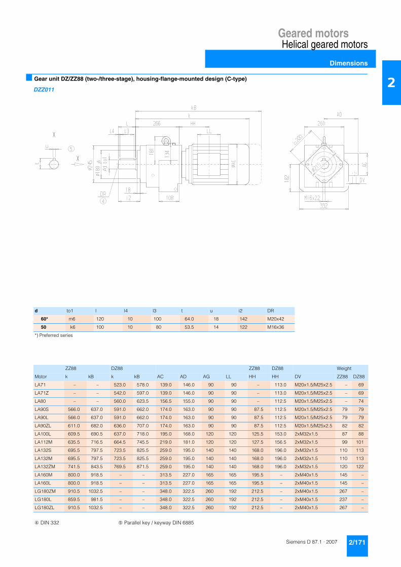
Geared motorsHelical geared motors
Dimensions
2/171Siemens D 87.1 · 2007
2■ Gear unit DZ/ZZ88 (two-/three-stage), housing-flange-mounted design (C-type)
DZZ011
d to1 l l4 l3 t u i2 DR
60* m6 120 10 100 64.0 18 142 M20x42
50 k6 100 10 80 53.5 14 122 M16x36
*) Preferred series
ZZ88 DZ88 ZZ88 DZ88 Weight
Motor k kB k kB AC AD AG LL HH HH DV ZZ88 DZ88
LA71 – – 523.0 578.0 139.0 146.0 90 90 – 113.0 M20x1.5/M25x2.5 – 69
LA71Z – – 542.0 597.0 139.0 146.0 90 90 – 113.0 M20x1.5/M25x2.5 – 69
LA80 – – 560.0 623.5 156.5 155.0 90 90 – 112.5 M20x1.5/M25x2.5 – 74
LA90S 566.0 637.0 591.0 662.0 174.0 163.0 90 90 87.5 112.5 M20x1.5/M25x2.5 79 79
LA90L 566.0 637.0 591.0 662.0 174.0 163.0 90 90 87.5 112.5 M20x1.5/M25x2.5 79 79
LA90ZL 611.0 682.0 636.0 707.0 174.0 163.0 90 90 87.5 112.5 M20x1.5/M25x2.5 82 82
LA100L 609.5 690.5 637.0 718.0 195.0 168.0 120 120 125.5 153.0 2xM32x1.5 87 88
LA112M 635.5 716.5 664.5 745.5 219.0 181.0 120 120 127.5 156.5 2xM32x1.5 99 101
LA132S 695.5 797.5 723.5 825.5 259.0 195.0 140 140 168.0 196.0 2xM32x1.5 110 113
LA132M 695.5 797.5 723.5 825.5 259.0 195.0 140 140 168.0 196.0 2xM32x1.5 110 113
LA132ZM 741.5 843.5 769.5 871.5 259.0 195.0 140 140 168.0 196.0 2xM32x1.5 120 122
LA160M 800.0 918.5 – – 313.5 227.0 165 165 195.5 – 2xM40x1.5 145 –
LA160L 800.0 918.5 – – 313.5 227.0 165 165 195.5 – 2xM40x1.5 145 –
LG180ZM 910.5 1032.5 – – 348.0 322.5 260 192 212.5 – 2xM40x1.5 267 –
LG180L 859.5 981.5 – – 348.0 322.5 260 192 212.5 – 2xM40x1.5 237 –
LG180ZL 910.5 1032.5 – – 348.0 322.5 260 192 212.5 – 2xM40x1.5 267 –
➃ DIN 332 ➄ Parallel key / keyway DIN 6885

Geared motorsHelical geared motors
Dimensions
2/172 Siemens D 87.1 · 2007
2 ■ Gear unit D/Z108 (two-/three-stage), foot-mounted design
DZ011
d to1 l l4 l3 t u i DR
70* m6 140 15 110 74.5 20 179.5M20x42
60 m6 120 10 100 64.0 18 159.5
*) Preferred series
Z108 D108 Z108 D108 Weight
Motor k kB k kB AC AD AG LL HH HH DV Z108 D108
LA80 – – 599.0 662.5 156.5 155.0 90 90 – 106.5 M20x1.5/M25x2.5 – 130
LA90S 599.5 670.5 630.0 701.0 174.0 163.0 90 90 76.0 106.5 M20x1.5/M25x2.5 133 135
LA90L 599.5 670.5 630.0 701.0 174.0 163.0 90 90 76.0 106.5 M20x1.5/M25x2.5 133 135
LA90ZL 644.5 715.5 675.0 746.0 174.0 163.0 90 90 76.0 106.5 M20x1.5/M25x2.5 136 138
LA100L 642.5 723.5 676.0 757.0 195.0 168.0 120 120 113.5 147.0 2xM32x1.5 141 144
LA112M 669.0 750.0 700.5 781.5 219.0 181.0 120 120 116.0 147.5 2xM32x1.5 152 156
LA132S 728.0 830.0 760.5 862.5 259.0 195.0 140 140 155.5 188.0 2xM32x1.5 163 168
LA132M 728.0 830.0 760.5 862.5 259.0 195.0 140 140 155.5 188.0 2xM32x1.5 163 168
LA132ZM 774.0 876.0 806.5 908.5 259.0 195.0 140 140 155.5 188.0 2xM32x1.5 172 177
LA160M 833.5 952.0 863.0 981.5 313.5 227.0 165 165 184.0 213.5 2xM40x1.5 198 205
LA160L 833.5 952.0 863.0 981.5 313.5 227.0 165 165 184.0 213.5 2xM40x1.5 198 205
LG180ZM 941.0 1063.0 – – 348.0 322.5 260 192 198.0 – 2xM40x1.5 324 –
LG180L 890.0 1012.0 – – 348.0 322.5 260 192 198.0 – 2xM40x1.5 294 –
LG180ZL 941.0 1063.0 – – 348.0 322.5 260 192 198.0 – 2xM40x1.5 324 –
LG200L 946.0 1072.0 – – 385.0 301.0 260 192 228.0 – 2xM50x1.5 374 –
LG225S* 1207.5 AA – – 442.0 325.0 260 192 196.5 – 2xM50x1.5 530 –
LG225M* 1207.5 AA – – 442.0 325.0 260 192 196.5 – 2xM50x1.5 518 –
LG225ZM* 1267.5 AA – – 442.0 325.0 260 192 196.5 – 2xM50x1.5 576 –
➃ DIN 332 ➄ Parallel key / keyway DIN 6885 * Incl. adapter AA On request

Geared motorsHelical geared motors
Dimensions
2/173Siemens D 87.1 · 2007
2■ Gear unit DF/ZF108 (two-/three-stage), flange-mounted design (A-type)
DZF011
Flange a1 b1 to2 c1 e1 f1 q1 s1 d to1 l l4 l3 t u i2 DR
A350 350 250 h6 18 300 5 36 17.5 70 m6 140 15 110 74.5 20 140M20x42
60 m6 120 10 100 64.0 18 120
A450 450 350 h6 20 400 5 34 17.5 70 m6 140 15 110 74.5 20 140M20x42
60 m6 120 10 100 64.0 18 120
ZF108 DF108 ZF108 DF108 Weight
Motor k kB k kB AC AD AG LL HH HH DV ZF108 DF108
LA80 – – 599.0 662.5 156.5 155.0 90 90 – 106.5 M20x1.5/M25x2.5 – 129
LA90S 599.5 670.5 630.0 701.0 174.0 163.0 90 90 76.0 106.5 M20x1.5/M25x2.5 131 134
LA90L 599.5 670.5 630.0 701.0 174.0 163.0 90 90 76.0 106.5 M20x1.5/M25x2.5 131 134
LA90ZL 644.5 715.5 675.0 746.0 174.0 163.0 90 90 76.0 106.5 M20x1.5/M25x2.5 134 137
LA100L 642.5 727.5 676.0 757.0 195.0 168.0 120 120 113.5 147.0 2xM32x1.5 139 143
LA112M 669.0 750.0 700.5 781.5 219.0 181.0 120 120 116.0 147.5 2xM32x1.5 151 155
LA132S 728.0 830.0 760.5 862.5 259.0 195.0 140 140 155.5 188.0 2xM32x1.5 162 167
LA132M 728.0 830.0 760.5 862.5 259.0 195.0 140 140 155.5 188.0 2xM32x1.5 162 167
LA132ZM 774.0 876.0 806.5 908.5 259.0 195.0 140 140 155.5 188.0 2xM32x1.5 171 176
LA160M 833.5 952.0 863.0 981.5 313.5 227.0 165 165 184.0 213.5 2xM40x1.5 196 204
LA160L 833.5 952.0 863.0 981.5 313.5 227.0 165 165 184.0 213.5 2xM40x1.5 196 204
LG180ZM 941.0 1063.0 – – 348.0 322.5 260 192 198.0 – 2xM40x1.5 323 –
LG180L 890.0 1012.0 – – 348.0 322.5 260 192 198.0 – 2xM40x1.5 293 –
LG180ZL 941.0 1063.0 – – 348.0 322.5 260 192 198.0 – 2xM40x1.5 323 –
LG200L 946.0 1072.0 – – 385.0 301.0 260 192 228.0 – 2xM50x1.5 373 –
LG225S* 1207.5 AA – – 442.0 325.0 260 192 196.5 – 2xM50x1.5 529 –
LG225M* 1207.5 AA – – 442.0 325.0 260 192 196.5 – 2xM50x1.5 517 –
LG225ZM* 1267.5 AA – – 442.0 325.0 260 192 196.5 – 2xM50x1.5 575 –
➃ DIN 332 ➄ Parallel key / keyway DIN 6885 * Incl. adapter AA On request

Geared motorsHelical geared motors
Dimensions
2/174 Siemens D 87.1 · 2007
2 ■ Gear unit DZ/ZZ108 (two-/three-stage), housing-flange-mounted design (C-type)
DZZ011
d to1 l l4 l3 t u i2 DR
70* m6 140 15 110 74.5 20 168M20x42
60 m6 120 10 100 64.0 18 148
*) Preferred series
ZZ108 DZ108 ZZ108 DZ108 Weight
Motor k kB k kB AC AD AG LL HH HH DV ZZ108 DZ108
LA80 – – 599.0 662.5 156.5 155.0 90 90 – 106.5 M20x1.5/M25x2.5 – 121
LA90S 599.5 670.5 630.0 701.0 174.0 163.0 90 90 76.0 106.5 M20x1.5/M25x2.5 124 126
LA90L 599.5 670.5 630.0 701.0 174.0 163.0 90 90 76.0 106.5 M20x1.5/M25x2.5 124 126
LA90ZL 644.5 715.5 675.0 746.0 174.0 163.0 90 90 76.0 106.5 M20x1.5/M25x2.5 127 129
LA100L 642.5 727.5 676.0 757.0 195.0 168.0 120 120 113.5 147.0 2xM32x1.5 132 135
LA112M 669.0 750.0 700.5 781.5 219.0 181.0 120 120 116.0 147.5 2xM32x1.5 144 147
LA132S 728.0 830.0 760.5 862.5 259.0 195.0 140 140 155.5 188.0 2xM32x1.5 154 159
LA132M 728.0 830.0 760.5 862.5 259.0 195.0 140 140 155.5 188.0 2xM32x1.5 154 159
LA132ZM 774.0 876.0 806.5 908.5 259.0 195.0 140 140 155.5 188.0 2xM32x1.5 163 168
LA160M 833.5 952.0 863.0 981.5 313.5 227.0 165 165 184.0 213.5 2xM40x1.5 189 196
LA160L 833.5 952.0 863.0 981.5 313.5 227.0 165 165 184.0 213.5 2xM40x1.5 189 196
LG180ZM 941.0 1063.0 – – 348.0 322.5 260 192 198.0 – 2xM40x1.5 315 –
LG180L 890.0 1012.0 – – 348.0 322.5 260 192 198.0 – 2xM40x1.5 285 –
LG180ZL 941.0 1063.0 – – 348.0 322.5 260 192 198.0 – 2xM40x1.5 315 –
LG200L 946.0 1072.0 – – 385.0 301.0 260 192 228.0 – 2xM50x1.5 365 –
LG225S* 1207.5 AA – – 442.0 325.0 260 192 196.5 – 2xM50x1.5 521 –
LG225M* 1207.5 AA – – 442.0 325.0 260 192 196.5 – 2xM50x1.5 509 –
LG225ZM* 1267.5 AA – – 442.0 325.0 260 192 196.5 – 2xM50x1.5 567 –
➃ DIN 332 ➄ Parallel key / keyway DIN 6885 ➆ For note, see page 2/191* Incl. adapter AA On request

Geared motorsHelical geared motors
Dimensions
2/175Siemens D 87.1 · 2007
2■ Gear unit D/Z128 (two-/three-stage), foot-mounted design
DZ011
d to1 l l4 l3 t u i DR
90* m6 170 15 140 95.0 25 215 M24x50
70 m6 140 15 110 74.5 20 185 M20x42
*) Preferred series
Z128 D128 Z128 D128 Weight
Motor k kB k kB AC AD AG LL HH HH DV Z128 D128
LA90S – – 686.0 757.0 174.0 163.0 90 90 – 99.5 M20x1.5/M25x2.5 – 212
LA90L – – 686.0 757.0 174.0 163.0 90 90 – 99.5 M20x1.5/M25x2.5 – 212
LA90ZL – – 731.0 802.0 174.0 163.0 90 90 – 99.5 M20x1.5/M25x2.5 – 215
LA100L 696.0 777.0 732.0 813.0 195.0 168.0 120 120 104.0 140.0 2xM32x1.5 214 221
LA112M 721.5 802.5 755.5 836.5 219.0 181.0 120 120 105.5 139.5 2xM32x1.5 226 233
LA132S 780.5 882.5 814.5 916.5 259.0 195.0 140 140 145.0 179.0 2xM32x1.5 235 246
LA132M 780.5 882.5 814.5 916.5 259.0 195.0 140 140 145.0 179.0 2xM32x1.5 235 246
LA132ZM 826.5 928.5 860.5 962.5 259.0 195.0 140 140 145.0 179.0 2xM32x1.5 244 255
LA160M 880.0 998.5 917.0 1035.5 313.5 227.0 165 165 167.5 204.5 2xM40x1.5 274 282
LA160L 880.0 998.5 917.0 1035.5 313.5 227.0 165 165 167.5 204.5 2xM40x1.5 274 282
LG180ZM 990.5 1112.5 1027.5 1149.5 348.0 322.5 260 192 184.5 221.5 2xM40x1.5 395 408
LG180L 939.5 1061.5 976.5 1098.5 348.0 322.5 260 192 184.5 221.5 2xM40x1.5 365 378
LG180ZL 990.5 1112.5 1027.5 1149.5 348.0 322.5 260 192 184.5 221.5 2xM40x1.5 395 408
LG200L 995.5 1121.5 1032.5 1158.5 385.0 301.0 260 192 214.5 251.5 2xM50x1.5 445 458
LG225S 1068.0 AA – – 439.0 325.0 260 192 250.0 – 2xM50x1.5 522 –
LG225M 1068.0 AA – – 439.0 325.0 260 192 250.0 – 2xM50x1.5 510 –
LG225ZM 1128.0 AA – – 439.0 325.0 260 192 250.0 – 2xM50x1.5 568 –
LG250M* 1356.5 AA – – 489.0 392.0 300 236 237.5 – 2xM63x1.5 689 –
LG250ZM* 1426.5 AA – – 489.0 392.0 300 236 237.5 – 2xM63x1.5 792 –
➃ DIN 332 ➄ Parallel key / keyway DIN 6885 * Incl. adapter AA On request

Geared motorsHelical geared motors
Dimensions
2/176 Siemens D 87.1 · 2007
2 ■ Gear unit DF/ZF128 (two-/three-stage), flange-mounted design (A-type)
DZF011
* If torque > 3,500 Nm, the flange must be pinned. We recommend you use 2 pins with a 12 mm diameter.
Flange a1 b1 to2 c1 e1 f1 q1 s1 d to1 l l4 l3 t u i2 DR
A350 * 350 250 h6 18 300 5 60 17.5 90 m6 170 15 140 95.0 25 170 M24x50
70 m6 140 15 110 74.5 20 140 M20x42
A450 450 350 h6 22 400 5 56 17.5 90 m6 170 15 140 95.0 25 170 M24x50
70 m6 140 15 110 74.5 20 140 M20x42
A550 550 450 h6 22 500 5 56 17.5 90 m6 170 15 140 95.0 25 170 M24x50
70 m6 140 15 110 74.5 20 140 M20x42
ZF128 DF128 ZF128 DF128 Weight
Motor k kB k kB AC AD AG LL HH HH DV ZF128 DF128
LA90S – – 686.0 757.0 174.0 163.0 90 90 – 99.5 M20x1.5/M25x2.5 – 206
LA90L – – 686.0 757.0 174.0 163.0 90 90 – 99.5 M20x1.5/M25x2.5 – 206
LA90ZL – – 731.0 802.0 174.0 163.0 90 90 – 99.5 M20x1.5/M25x2.5 – 209
LA100L 696.0 777.0 732.0 813.0 195.0 168.0 120 120 104.0 140.0 2xM32x1.5 209 216
LA112M 721.5 802.5 755.5 836.5 219.0 181.0 120 120 105.5 139.5 2xM32x1.5 220 227
LA132S 780.5 882.5 814.5 916.5 259.0 195.0 140 140 145.0 179.0 2xM32x1.5 230 240
LA132M 780.5 882.5 814.5 916.5 259.0 195.0 140 140 145.0 179.0 2xM32x1.5 230 240
LA132ZM 826.5 928.5 860.5 962.5 259.0 195.0 140 140 145.0 179.0 2xM32x1.5 239 249
LA160M 880.0 998.5 917.0 1035.5 313.5 227.0 165 165 167.5 204.5 2xM40x1.5 269 276
LA160L 880.0 998.5 917.0 1035.5 313.5 227.0 165 165 167.5 204.5 2xM40x1.5 269 276
LG180ZM 990.5 1112.5 1027.5 1149.5 348.0 322.5 260 192 184.5 221.5 2xM40x1.5 390 402
LG180L 939.5 1061.5 976.5 1098.5 348.0 322.5 260 192 184.5 221.5 2xM40x1.5 360 372
LG180ZL 990.5 1112.5 1027.5 1149.5 348.0 322.5 260 192 184.5 221.5 2xM40x1.5 390 402
LG200L 995.5 1121.5 1032.5 1158.5 385.0 301.0 260 192 214.5 251.5 2xM50x1.5 440 452
LG225S 1068.0 AA – – 439.0 325.0 260 192 250.0 – 2xM50x1.5 517 –
LG225M 1068.0 AA – – 439.0 325.0 260 192 250.0 – 2xM50x1.5 505 –
LG225ZM 1128.0 AA – – 439.0 325.0 260 192 250.0 – 2xM50x1.5 563 –
LG250M* 1356.5 AA – – 489.0 392.0 300 236 237.5 – 2xM63x1.5 684 –
LG250ZM* 1426.5 AA – – 489.0 392.0 300 236 237.5 – 2xM63x1.5 787 –
➃ DIN 332 ➄ Parallel key / keyway DIN 6885 * Incl. adapter AA On request

Geared motorsHelical geared motors
Dimensions
2/177Siemens D 87.1 · 2007
2■ Gear unit DZ/ZZ128 (two-/three-stage), housing-flange-mounted design (C-type)
DZZ011
d to1 l l4 l3 t u i2 DR
90* m6 170 15 140 95.0 25 203 M24x50
70 m6 140 15 110 74.5 20 173 M20x42
*) Preferred series
ZZ128 DZ128 ZZ128 DZ128 Weight
Motor k kB k kB AC AD AG LL HH HH DV ZZ128 DZ128
LA90S – – 686.0 757.0 174.0 163.0 90 90 – 99.5 M20x1.5/M25x2.5 – 190
LA90L – – 686.0 757.0 174.0 163.0 90 90 – 99.5 M20x1.5/M25x2.5 – 190
LA90ZL – – 731.0 802.0 174.0 163.0 90 90 – 99.5 M20x1.5/M25x2.5 – 192
LA100L 696.0 777.0 732.0 813.0 195.0 168.0 120 120 104.0 140.0 2xM32x1.5 192 199
LA112M 721.5 802.5 755.5 836.5 219.0 181.0 120 120 105.5 139.5 2xM32x1.5 203 210
LA132S 780.5 882.5 814.5 916.5 259.0 195.0 140 140 145.0 179.0 2xM32x1.5 213 223
LA132M 780.5 882.5 814.5 916.5 259.0 195.0 140 140 145.0 179.0 2xM32x1.5 213 223
LA132ZM 826.5 928.5 860.5 962.5 259.0 195.0 140 140 145.0 179.0 2xM32x1.5 222 233
LA160M 880.0 998.5 917.0 1035.5 313.5 227.0 165 165 167.5 204.5 2xM40x1.5 252 259
LA160L 880.0 998.5 917.0 1035.5 313.5 227.0 165 165 167.5 204.5 2xM40x1.5 252 259
LG180ZM 990.5 1112.5 1027.5 1149.5 348.0 322.5 260 192 184.5 221.5 2xM40x1.5 373 385
LG180L 939.5 1061.5 976.5 1098.5 348.0 322.5 260 192 184.5 221.5 2xM40x1.5 343 355
LG180ZL 990.5 1112.5 1027.5 1149.5 348.0 322.5 260 192 184.5 221.5 2xM40x1.5 373 385
LG200L 995.5 1121.5 1032.5 1158.5 385.0 301.0 260 192 214.5 251.5 2xM50x1.5 423 435
LG225S 1068.0 AA – – 439.0 325.0 260 192 250.0 – 2xM50x1.5 500 –
LG225M 1068.0 AA – – 439.0 325.0 260 192 250.0 – 2xM50x1.5 488 –
LG225ZM 1128.0 AA – – 439.0 325.0 260 192 250.0 – 2xM50x1.5 546 –
LG250M* 1356.5 AA – – 489.0 392.0 300 236 237.5 – 2xM63x1.5 667 –
LG250ZM* 1426.5 AA – – 489.0 392.0 300 236 237.5 – 2xM63x1.5 770 –
➃ DIN 332 ➄ Parallel key / keyway DIN 6885 ➆ For note, see page 2/191* Incl. adapter AA On request

Geared motorsHelical geared motors
Dimensions
2/178 Siemens D 87.1 · 2007
2 ■ Gear unit D/Z148 (two-/three-stage), foot-mounted design
DZ011
d to1 l l4 l3 t u i DR
100* m6 210 15 180 106 28 260M24x50
90 m6 170 15 140 95 25 220
*) Preferred series
Z148 D148 Z148 D148 Weight
Motor k kB k kB AC AD AG LL HH HH DV Z148 D148
LA100L – – 764.0 845.0 195.0 168.0 120 120 – 135.0 2xM32x1.5 – 313
LA112M – – 789.5 870.5 219.0 181.0 120 120 – 136.5 2xM32x1.5 – 324
LA132S 809.5 911.5 847.5 949.5 259.0 195.0 140 140 137.0 175.0 2xM32x1.5 325 336
LA132M 809.5 911.5 847.5 949.5 259.0 195.0 140 140 137.0 175.0 2xM32x1.5 325 336
LA132ZM 855.5 957.5 893.5 995.5 259.0 195.0 140 140 137.0 175.0 2xM32x1.5 334 345
LA160M 909.5 1028.0 947.5 1066.0 313.5 227.0 165 165 160.0 198.0 2xM40x1.5 359 371
LA160L 909.5 1028.0 947.5 1066.0 313.5 227.0 165 165 160.0 198.0 2xM40x1.5 359 371
LG180ZM 1020.0 1142.0 1058.0 1180.0 348.0 322.5 260 192 177.0 215.0 2xM40x1.5 485 497
LG180L 969.0 1091.0 1007.0 1129.0 348.0 322.5 260 192 177.0 215.0 2xM40x1.5 455 467
LG180ZL 1020.0 1142.0 1058.0 1180.0 348.0 322.5 260 192 177.0 215.0 2xM40x1.5 485 497
LG200L 1025.0 1151.0 1063.0 1189.0 385.0 301.0 260 192 207.0 245.0 2xM50x1.5 535 547
LG225S 1097.5 AA 1135.5 AA 439.0 325.0 260 192 242.5 280.5 2xM50x1.5 608 621
LG225M 1097.5 AA 1135.5 AA 439.0 325.0 260 192 242.5 280.5 2xM50x1.5 596 609
LG225ZM 1157.5 AA 1195.5 AA 439.0 325.0 260 192 242.5 280.5 2xM50x1.5 654 667
LG250M 1192.5 AA – – 489.0 392.0 300 236 278.0 – 2xM63x1.5 698 –
LG250ZM 1262.5 AA – – 489.0 392.0 300 236 278.0 – 2xM63x1.5 801 –
LG280S* 1468.5 AA – – 540.0 432.0 300 236 252.5 – 2xM63x1.5 929 –
LG280M* 1468.5 AA – – 540.0 432.0 300 236 252.5 – 2xM63x1.5 941 –
LG280ZM* 1578.5 AA – – 540.0 432.0 300 236 252.5 – 2xM63x1.5 1029 –
➃ DIN 332 ➄ Parallel key / keyway DIN 6885 * Incl. adapter AA On request

Geared motorsHelical geared motors
Dimensions
2/179Siemens D 87.1 · 2007
2■ Gear unit DF/ZF148 (two-/three-stage), flange-mounted design (A-type)
DZF011
Flange a1 b1 to2 c1 e1 f1 q1 s1 d to1 l l4 l3 t u i2 DR
A450 450 350 h6 22 400 5 68 17.5 100 m6 210 15 180 106 28 210M24x50
90 m6 170 15 140 95 25 170
A550 550 450 h6 25 500 5 65 17.5 100 m6 210 15 180 106 28 210M24x50
90 m6 170 15 140 95 25 170
ZF148 DF148 ZF148 DF148 Weight
Motor k kB k kB AC AD AG LL HH HH DV ZF148 DF148
LA100L – – 764.0 845.0 195.0 168.0 120 120 – 135.0 2xM32x1.5 – 307
LA112M – – 789.5 870.5 219.0 181.0 120 120 – 136.5 2xM32x1.5 – 318
LA132S 809.5 911.5 847.5 949.5 259.0 195.0 140 140 137.0 175.0 2xM32x1.5 319 330
LA132M 809.5 911.5 847.5 949.5 259.0 195.0 140 140 137.0 175.0 2xM32x1.5 319 330
LA132ZM 855.5 957.5 893.5 995.5 259.0 195.0 140 140 137.0 175.0 2xM32x1.5 328 339
LA160M 909.5 1028.0 947.5 1066.0 313.5 227.0 165 165 160.0 198.0 2xM40x1.5 353 365
LA160L 909.5 1028.0 947.5 1066.0 313.5 227.0 165 165 160.0 198.0 2xM40x1.5 353 365
LG180ZM 1020.0 1142.0 1058.0 1180.0 348.0 322.5 260 192 177.0 215.0 2xM40x1.5 479 491
LG180L 969.0 1091.0 1007.0 1129.0 348.0 322.5 260 192 177.0 215.0 2xM40x1.5 449 461
LG180ZL 1020.0 1142.0 1058.0 1180.0 348.0 322.5 260 192 177.0 215.0 2xM40x1.5 479 491
LG200L 1025.0 1151.0 1063.0 1189.0 385.0 301.0 260 192 207.0 245.0 2xM50x1.5 529 541
LG225S 1097.5 AA 1135.5 AA 439.0 325.0 260 192 242.5 280.5 2xM50x1.5 602 615
LG225M 1097.5 AA 1135.5 AA 439.0 325.0 260 192 242.5 280.5 2xM50x1.5 590 603
LG225ZM 1157.5 AA 1195.5 AA 439.0 325.0 260 192 242.5 280.5 2xM50x1.5 648 661
LG250M 1192.5 AA – – 489.0 392.0 300 236 278.0 – 2xM63x1.5 692 –
LG250ZM 1262.5 AA – – 489.0 392.0 300 236 278.0 – 2xM63x1.5 795 –
LG280S* 1468.5 AA – – 540.0 432.0 300 236 252.5 – 2xM63x1.5 923 –
LG280M* 1468.5 AA – – 540.0 432.0 300 236 252.5 – 2xM63x1.5 941 –
LG280ZM* 1578.5 AA – – 540.0 432.0 300 236 252.5 – 2xM63x1.5 1029 –
➃ DIN 332 ➄ Parallel key / keyway DIN 6885 * Incl. adapter AA On request

Geared motorsHelical geared motors
Dimensions
2/180 Siemens D 87.1 · 2007
2 ■ Gear unit DZ/ZZ148 (two-/three-stage), housing-flange-mounted design (C-type)
DZZ011
d to1 l l4 l3 t u i2 DR
100* m6 210 15 180 106 28 243M24x50
90 m6 170 15 140 95 25 203
*) Preferred series
ZZ148 DZ148 ZZ148 DZ148 Weight
Motor k kB k kB AC AD AG LL HH HH DV ZZ148 DZ148
LA100L – – 764.0 845.0 195.0 168.0 120 120 – 135.0 2xM32x1.5 – 283
LA112M – – 789.5 870.5 219.0 181.0 120 120 – 136.5 2xM32x1.5 – 294
LA132S 809.5 911.5 847.5 949.5 259.0 195.0 140 140 137.0 175.0 2xM32x1.5 302 306
LA132M 809.5 911.5 847.5 949.5 259.0 195.0 140 140 137.0 175.0 2xM32x1.5 302 306
LA132ZM 855.5 957.5 893.5 995.5 259.0 195.0 140 140 137.0 175.0 2xM32x1.5 311 315
LA160M 909.5 1028.0 947.5 1066.0 313.5 227.0 165 165 160.0 198.0 2xM40x1.5 336 341
LA160L 909.5 1028.0 947.5 1066.0 313.5 227.0 165 165 160.0 198.0 2xM40x1.5 336 341
LG180ZM 1020.0 1142.0 1058.0 1180.0 348.0 322.5 260 192 177.0 215.0 2xM40x1.5 462 467
LG180L 969.0 1091.0 1007.0 1129.0 348.0 322.5 260 192 177.0 215.0 2xM40x1.5 432 437
LG180ZL 1020.0 1142.0 1058.0 1180.0 348.0 322.5 260 192 177.0 215.0 2xM40x1.5 462 467
LG200L 1025.0 1151.0 1063.0 1189.0 385.0 301.0 260 192 207.0 245.0 2xM50x1.5 512 517
LG225S 1097.5 AA 1135.5 AA 439.0 325.0 260 192 242.5 AA 2xM50x1.5 585 547
LG225M 1097.5 AA 1135.5 AA 439.0 325.0 260 192 242.5 AA 2xM50x1.5 573 591
LG225ZM 1157.5 AA 1195.5 AA 439.0 325.0 260 192 242.5 AA 2xM50x1.5 631 637
LG250M 1192.5 AA – – 489.0 392.0 300 236 278.0 – 2xM63x1.5 675 –
LG250ZM 1262.5 AA – – 489.0 392.0 300 236 278.0 – 2xM63x1.5 778 –
LG280S* 1468.5 AA – – 540.0 432.0 300 236 252.5 – 2xM63x1.5 906 –
LG280M* 1468.5 AA – – 540.0 432.0 300 236 252.5 – 2xM63x1.5 918 –
LG280ZM* 1578.5 AA – – 540.0 432.0 300 236 252.5 – 2xM63x1.5 1006 –
➃ DIN 332 ➄ Parallel key / keyway DIN 6885 ➆ For note, see page 2/191* Incl. adapter AA On request

Geared motorsHelical geared motors
Dimensions
2/181Siemens D 87.1 · 2007
2■ Gear unit D/Z168 (two-/three-stage), foot-mounted design
DZ011
d to1 l l4 l3 t u i DR
120* m6 210 15 180 127 32 260M24x50
100 m6 210 15 180 106 28 260
*) Preferred series
Z168 D168 Z168 D168 Weight
Motor k kB k kB AC AD AG LL HH HH DV Z168 D168
LA132S 878.0 980.0 919.0 1021.0 259.0 195.0 140 140 122.5 163.5 2xM32x1.5 491 508
LA132M 878.0 980.0 919.0 1021.0 259.0 195.0 140 140 122.5 163.5 2xM32x1.5 491 508
LA132ZM 924.0 1026.0 965.0 1067.0 259.0 195.0 140 140 122.5 163.5 2xM32x1.5 500 517
LA160M 978.0 1096.5 1019.0 1137.5 313.5 227.0 165 165 145.5 186.5 2xM40x1.5 524 543
LA160L 978.0 1096.5 1019.0 1137.5 313.5 227.0 165 165 145.5 186.5 2xM40x1.5 524 543
LG180ZM 1088.5 1210.5 1129.5 1251.5 348.0 322.5 260 192 162.5 203.5 2xM40x1.5 650 669
LG180L 1037.5 1159.5 1078.5 1200.5 348.0 322.5 260 192 162.5 203.5 2xM40x1.5 620 639
LG180ZL 1088.5 1210.5 1129.5 1251.5 348.0 322.5 260 192 162.5 203.5 2xM40x1.5 650 669
LG200L 1093.5 1219.5 1134.5 1260.5 385.0 301.0 260 192 192.5 233.5 2xM50x1.5 700 719
LG225S 1166.0 AA 1207.0 AA 439.0 325.0 260 192 228.0 269.0 2xM50x1.5 772 792
LG225M 1166.0 AA 1207.0 AA 439.0 325.0 260 192 228.0 269.0 2xM50x1.5 760 780
LG225ZM 1226.0 AA 1267.0 AA 439.0 325.0 260 192 228.0 269.0 2xM50x1.5 818 838
LG250M 1261.0 AA – – 489.0 392.0 300 236 263.5 – 2xM63x1.5 862 –
LG250ZM 1331.0 AA – – 489.0 392.0 300 236 263.5 – 2xM63x1.5 965 –
LG280S* 1537.5 AA – – 540.0 432.0 300 236 252.5 – 2xM63x1.5 991 –
LG280M* 1537.5 AA – – 540.0 432.0 300 236 252.5 – 2xM63x1.5 1097 –
LG280ZM* 1647.5 AA – – 540.0 432.0 300 236 252.5 – 2xM63x1.5 1185 –
➃ DIN 332 ➄ Parallel key / keyway DIN 6885 * Incl. adapter AA On request

Geared motorsHelical geared motors
Dimensions
2/182 Siemens D 87.1 · 2007
2 ■ Gear unit DF/ZF168 (two-/three-stage), flange-mounted design (A-type)
DZF011
Flange a1 b1 to2 c1 e1 f1 q1 s1 d to1 l l4 l3 t u i2 DR
A450 450 350 h6 31 400 5 65 17.5 120 m6 210 15 180 127 32 210M24x50
100 m6 210 15 180 106 28 210
A550 550 450 h6 31 500 5 65 17.5 120 m6 210 15 180 127 32 210M24x50
100 m6 210 15 180 106 28 210
A660 660 550 h6 31 600 5 65 22.0 120 m6 210 15 180 127 32 210M24x50
100 m6 210 15 180 106 28 210
ZF168 DF168 ZF168 DF168 Weight
Motor k kB k kB AC AD AG LL HH HH DV ZF168 DF168
LA132S 878.0 980.0 919.0 1021.0 259.0 195.0 140 140 122.5 163.5 2xM32x1.5 466 484
LA132M 878.0 980.0 919.0 1021.0 259.0 195.0 140 140 122.5 163.5 2xM32x1.5 466 484
LA132ZM 924.0 1026.0 965.0 1067.0 259.0 195.0 140 140 122.5 163.5 2xM32x1.5 475 493
LA160M 978.0 1096.5 1019.0 1137.5 313.5 227.0 165 165 145.5 186.5 2xM40x1.5 500 518
LA160L 978.0 1096.5 1019.0 1137.5 313.5 227.0 165 165 145.5 186.5 2xM40x1.5 500 518
LG180ZM 1088.5 1210.5 1129.5 1251.5 348.0 322.5 260 192 162.5 203.5 2xM40x1.5 625 644
LG180L 1037.5 1159.5 1078.5 1200.5 348.0 322.5 260 192 162.5 203.5 2xM40x1.5 595 614
LG180ZL 1088.5 1210.5 1129.5 1251.5 348.0 322.5 260 192 162.5 203.5 2xM40x1.5 625 644
LG200L 1093.5 1219.5 1134.5 1260.5 385.0 301.0 260 192 192.5 233.5 2xM50x1.5 675 694
LG225S 1166.0 AA 1207.0 AA 439.0 325.0 260 192 228.0 269.0 2xM50x1.5 747 767
LG225M 1166.0 AA 1207.0 AA 439.0 325.0 260 192 228.0 269.0 2xM50x1.5 735 755
LG225ZM 1226.0 AA 1267.0 AA 439.0 325.0 260 192 228.0 269.0 2xM50x1.5 793 813
LG250M 1261.0 AA – – 489.0 392.0 300 236 263.5 – 2xM63x1.5 837 –
LG250ZM 1331.0 AA – – 489.0 392.0 300 236 263.5 – 2xM63x1.5 940 –
LG280S* 1537.5 AA – – 540.0 432.0 300 236 252.5 – 2xM63x1.5 966 –
LG280M* 1537.5 AA – – 540.0 432.0 300 236 252.5 – 2xM63x1.5 1072 –
LG280ZM* 1647.5 AA – – 540.0 432.0 300 236 252.5 – 2xM63x1.5 1160 –
➃ DIN 332 ➄ Parallel key / keyway DIN 6885 * Incl. adapter AA On request

Geared motorsHelical geared motors
Dimensions
2/183Siemens D 87.1 · 2007
2■ Gear unit DZ/ZZ168 (two-/three-stage), housing-flange-mounted design (C-type)
DZZ011
d to1 l l4 l3 t u i2 DR
120* m6 210 15 180 127 32 251M24x50
100 m6 210 15 180 106 28 251
*) Preferred series
ZZ168 DZ168 ZZ168 DZ168 Weight
Motor k kB k kB AC AD AG LL HH HH DV ZZ168 DZ168
LA132S 878.0 980.0 919.0 1021.0 259.0 195.0 140 140 122.5 163.5 2xM32x1.5 447 465
LA132M 878.0 980.0 919.0 1021.0 259.0 195.0 140 140 122.5 163.5 2xM32x1.5 447 465
LA132ZM 924.0 1026.0 965.0 1067.0 259.0 195.0 140 140 122.5 163.5 2xM32x1.5 456 474
LA160M 978.0 1096.5 1019.0 1137.5 313.5 227.0 165 165 145.5 186.5 2xM40x1.5 481 499
LA160L 978.0 1096.5 1019.0 1137.5 313.5 227.0 165 165 145.5 186.5 2xM40x1.5 481 499
LG180ZM 1088.5 1210.5 1129.5 1251.5 348.0 322.5 260 192 162.5 203.5 2xM40x1.5 606 625
LG180L 1037.5 1159.5 1078.5 1200.5 348.0 322.5 260 192 162.5 203.5 2xM40x1.5 576 595
LG180ZL 1088.5 1210.5 1129.5 1251.5 348.0 322.5 260 192 162.5 203.5 2xM40x1.5 606 625
LG200L 1093.5 1219.5 1134.5 1260.5 385.0 301.0 260 192 192.5 233.5 2xM50x1.5 656 675
LG225S 1166.0 AA 1207.0 AA 439.0 325.0 260 192 228.0 269.0 2xM50x1.5 728 748
LG225M 1166.0 AA 1207.0 AA 439.0 325.0 260 192 228.0 269.0 2xM50x1.5 716 736
LG225ZM 1226.0 AA 1267.0 AA 439.0 325.0 260 192 228.0 269.0 2xM50x1.5 774 794
LG250M 1261.0 AA – – 489.0 392.0 300 236 263.5 – 2xM63x1.5 818 –
LG250ZM 1331.0 AA – – 489.0 392.0 300 236 263.5 – 2xM63x1.5 921 –
LG280S* 1537.5 AA – – 540.0 432.0 300 236 252.5 – 2xM63x1.5 947 –
LG280M* 1537.5 AA – – 540.0 432.0 300 236 252.5 – 2xM63x1.5 1053 –
LG280ZM* 1647.5 AA – – 540.0 432.0 300 236 252.5 – 2xM63x1.5 1141 –
➃ DIN 332 ➄ Parallel key / keyway DIN 6885 ➆ For note, see page 2/191* Incl. adapter AA On request
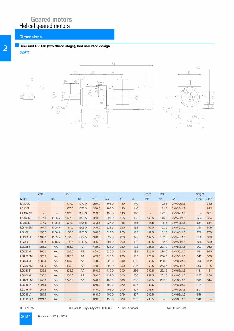
Geared motorsHelical geared motors
Dimensions
2/184 Siemens D 87.1 · 2007
2 ■ Gear unit D/Z188 (two-/three-stage), foot-mounted design
DZ011
Z188 D188 Z188 D188 Weight
Motor k kB k kB AC AD AG LL HH HH DV Z188 D188
LA132S – – 977.0 1079.0 259.0 195.0 140 140 – 122.5 2xM32x1.5 – 652
LA132M – – 977.0 1079.0 259.0 195.0 140 140 – 122.5 2xM32x1.5 – 652
LA132ZM – – 1023.0 1125.0 259.0 195.0 140 140 – 122.5 2xM32x1.5 – 661
LA160M 1077.0 1195.5 1077.0 1195.5 313.5 227.0 165 165 145.5 145.5 2xM40x1.5 654 684
LA160L 1077.0 1195.5 1077.0 1195.5 313.5 227.0 165 165 145.5 145.5 2xM40x1.5 654 684
LG180ZM 1187.5 1309.5 1187.5 1309.5 348.0 322.5 260 192 162.5 162.5 2xM40x1.5 780 809
LG180L 1136.5 1258.5 1136.5 1258.5 348.0 322.5 260 192 162.5 162.5 2xM40x1.5 750 779
LG180ZL 1187.5 1309.5 1187.5 1309.5 348.0 322.5 260 192 162.5 162.5 2xM40x1.5 780 809
LG200L 1192.5 1318.5 1192.5 1318.5 385.0 301.0 260 192 192.5 192.5 2xM50x1.5 830 859
LG225S 1265.0 AA 1265.0 AA 439.0 325.0 260 192 228.0 228.0 2xM50x1.5 903 932
LG225M 1265.0 AA 1265.0 AA 439.0 325.0 260 192 228.0 228.0 2xM50x1.5 891 920
LG225ZM 1325.0 AA 1325.0 AA 439.0 325.0 260 192 228.0 228.0 2xM50x1.5 949 978
LG250M 1360.0 AA 1360.0 AA 489.0 392.0 300 236 263.5 263.5 2xM63x1.5 993 1022
LG250ZM 1430.0 AA 1430.0 AA 489.0 392.0 300 236 263.5 263.5 2xM63x1.5 1096 1125
LG280S* 1636.5 AA 1636.5 AA 540.0 432.0 300 236 252.5 252.5 2xM63x1.5 1121 1151
LG280M* 1636.5 AA 1636.5 AA 540.0 432.0 300 236 252.5 252.5 2xM63x1.5 1227 1256
LG280ZM* 1746.5 AA 1746.5 AA 540.0 432.0 300 236 252.5 252.5 2xM63x1.5 1315 1344
LG315S* 1824.5 AA – – 610.0 495.0 379 307 285.5 – 2xM63x1.5 1421 –
LG315M* 1984.5 AA – – 610.0 495.0 379 307 285.5 – 2xM63x1.5 1501 –
LG315L* 1984.5 AA – – 610.0 495.0 379 307 285.5 – 2xM63x1.5 1646 –
LG315ZL* 2124.5 AA – – 610.0 495.0 379 307 285.5 – 2xM63x1.5 2048 –
➃ DIN 332 ➄ Parallel key / keyway DIN 6885 * Incl. adapter AA On request
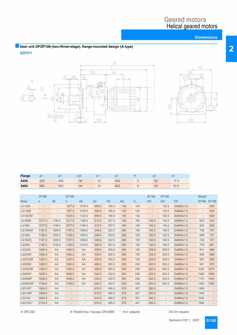
Geared motorsHelical geared motors
Dimensions
2/185Siemens D 87.1 · 2007
2■ Gear unit DF/ZF188 (two-/three-stage), flange-mounted design (A-type)
DZF011
Flange a1 b1 to2 c1 e1 f1 q1 s1
A550 550 450 h6 31 500 5 83 17.5
A660 660 550 h6 31 600 6 83 22.0
ZF188 DF188 ZF188 DF188 Weight
Motor k kB k kB AC AD AG LL HH HH DV ZF188 DF188
LA132S – – 977.0 1079.0 259.0 195.0 140 140 – 122.5 2xM32x1.5 – 600
LA132M – – 977.0 1079.0 259.0 195.0 140 140 – 122.5 2xM32x1.5 – 600
LA132ZM – – 1023.0 1125.0 259.0 195.0 140 140 – 122.5 2xM32x1.5 – 609
LA160M 1077.0 1195.5 1077.0 1195.5 313.5 227.0 165 165 145.5 145.5 2xM40x1.5 602 632
LA160L 1077.0 1195.5 1077.0 1195.5 313.5 227.0 165 165 145.5 145.5 2xM40x1.5 602 632
LG180ZM 1187.5 1309.5 1187.5 1309.5 348.0 322.5 260 192 162.5 162.5 2xM40x1.5 728 757
LG180L 1136.5 1258.5 1136.5 1258.5 348.0 322.5 260 192 162.5 162.5 2xM40x1.5 698 727
LG180ZL 1187.5 1309.5 1187.5 1309.5 348.0 322.5 260 192 162.5 162.5 2xM40x1.5 728 757
LG200L 1192.5 1318.5 1192.5 1318.5 385.0 301.0 260 192 192.5 192.5 2xM50x1.5 778 807
LG225S 1265.0 AA 1265.0 AA 439.0 325.0 260 192 228.0 228.0 2xM50x1.5 851 880
LG225M 1265.0 AA 1265.0 AA 439.0 325.0 260 192 228.0 228.0 2xM50x1.5 839 868
LG225ZM 1325.0 AA 1325.0 AA 439.0 325.0 260 192 228.0 228.0 2xM50x1.5 897 926
LG250M 1360.0 AA 1360.0 AA 489.0 392.0 300 236 263.5 263.5 2xM63x1.5 941 970
LG250ZM 1430.0 AA 1430.0 AA 489.0 392.0 300 236 263.5 263.5 2xM63x1.5 1044 1073
LG280S* 1636.5 AA 1636.5 AA 540.0 432.0 300 236 252.5 252.5 2xM63x1.5 1069 1099
LG280M* 1636.5 AA 1636.5 AA 540.0 432.0 300 236 252.5 252.5 2xM63x1.5 1175 1204
LG280ZM* 1746.5 AA 1746.5 AA 540.0 432.0 300 236 252.5 252.5 2xM63x1.5 1263 1292
LG315S* 1824.5 AA – – 610.0 495.0 379 307 285.5 – 2xM63x1.5 1369 –
LG315M* 1984.5 AA – – 610.0 495.0 379 307 285.5 – 2xM63x1.5 1449 –
LG315L* 1984.5 AA – – 610.0 495.0 379 307 285.5 – 2xM63x1.5 1594 –
LG315ZL* 2124.5 AA – – 610.0 495.0 379 307 285.5 – 2xM63x1.5 1998 –
➃ DIN 332 ➄ Parallel key / keyway DIN 6885 * Incl. adapter AA On request

Geared motorsHelical geared motors
Dimensions
2/186 Siemens D 87.1 · 2007
2 ■ Gear unit DZ/ZZ188 (two-/three-stage), housing-flange-mounted design (C-type)
DZZ011
ZZ188 DZ188 ZZ188 DZ188 Weight
Motor k kB k kB AC AD AG LL HH HH DV ZZ188 DZ188
LA132S – – 977.0 1079.0 259.0 195.0 140 140 – 122.5 2xM32x1.5 – 580
LA132M – – 977.0 1079.0 259.0 195.0 140 140 – 122.5 2xM32x1.5 – 580
LA132ZM – – 1023.0 1125.0 259.0 195.0 140 140 – 122.5 2xM32x1.5 – 589
LA160M 1077.0 1195.5 1077.0 1195.5 313.5 227.0 165 165 145.5 145.5 2xM40x1.5 582 612
LA160L 1077.0 1195.5 1077.0 1195.5 313.5 227.0 165 165 145.5 145.5 2xM40x1.5 582 612
LG180ZM 1187.5 1309.5 1187.5 1309.5 348.0 322.5 260 192 162.5 162.5 2xM40x1.5 708 737
LG180L 1136.5 1258.5 1136.5 1258.5 348.0 322.5 260 192 162.5 162.5 2xM40x1.5 678 707
LG180ZL 1187.5 1309.5 1187.5 1309.5 348.0 322.5 260 192 162.5 162.5 2xM40x1.5 708 737
LG200L 1192.5 1318.5 1192.5 1318.5 385.0 301.0 260 192 192.5 192.5 2xM50x1.5 758 787
LG225S 1265.0 AA 1265.0 AA 439.0 325.0 260 192 228.0 228.0 2xM50x1.5 831 860
LG225M 1265.0 AA 1265.0 AA 439.0 325.0 260 192 228.0 228.0 2xM50x1.5 819 848
LG225ZM 1325.0 AA 1325.0 AA 439.0 325.0 260 192 228.0 228.0 2xM50x1.5 877 906
LG250M 1360.0 AA 1360.0 AA 489.0 392.0 300 236 263.5 263.5 2xM63x1.5 921 950
LG250ZM 1430.0 AA 1430.0 AA 489.0 392.0 300 236 263.5 263.5 2xM63x1.5 1024 1053
LG280S* 1636.5 AA 1636.5 AA 540.0 432.0 300 236 252.5 252.5 2xM63x1.5 1049 1079
LG280M* 1636.5 AA 1636.5 AA 540.0 432.0 300 236 252.5 252.5 2xM63x1.5 1155 1184
LG280ZM* 1746.5 AA 1746.5 AA 540.0 432.0 300 236 252.5 252.5 2xM63x1.5 1243 1272
LG315S* 1824.5 AA – – 610.0 495.0 379 307 285.5 – 2xM63x1.5 1349 –
LG315M* 1984.5 AA – – 610.0 495.0 379 307 285.5 – 2xM63x1.5 1501 –
LG315L* 1984.5 AA – – 610.0 495.0 379 307 285.5 – 2xM63x1.5 1646 –
LG315ZL* 2124.5 AA – – 610.0 495.0 379 307 285.5 – 2xM63x1.5 2048 –
➃ DIN 332 ➄ Parallel key / keyway DIN 6885 ➆ For note, see page 2/191* Incl. adapter AA On request
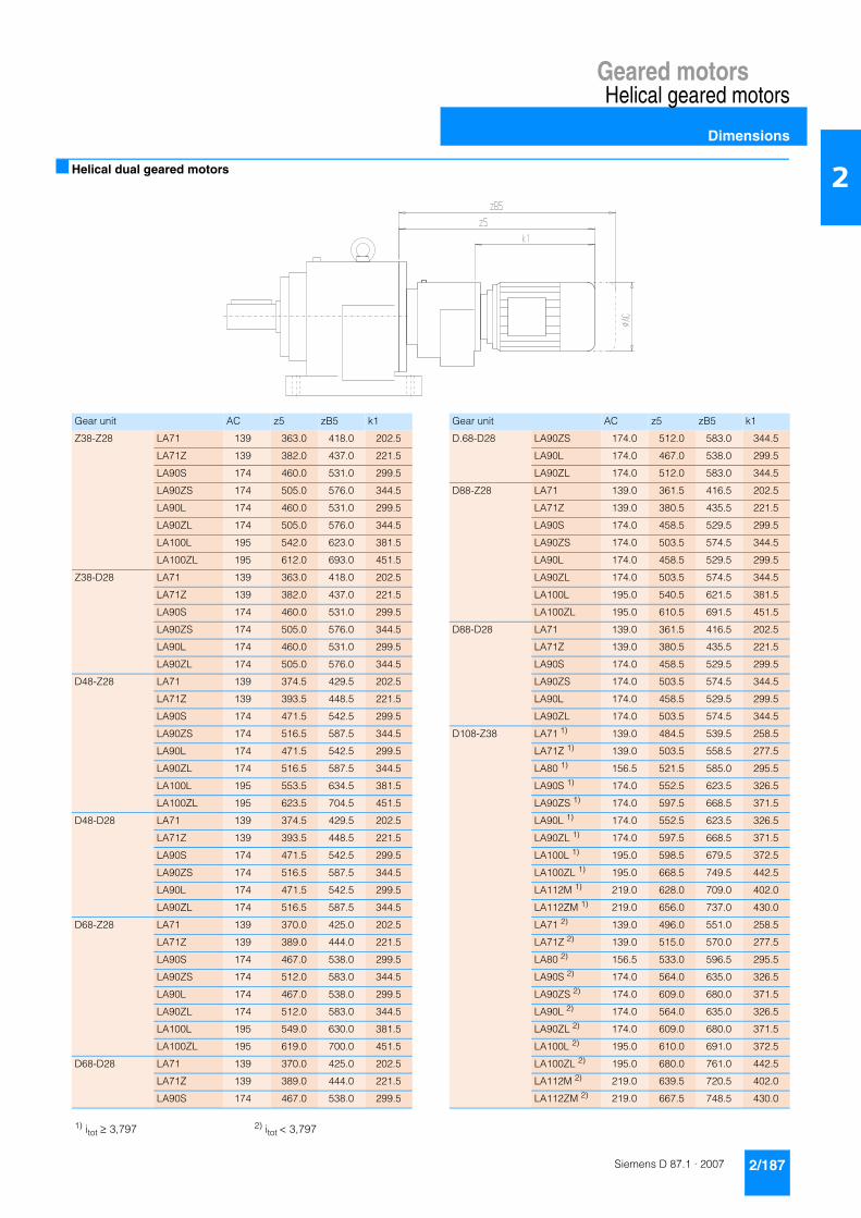
Geared motorsHelical geared motors
Dimensions
2/187Siemens D 87.1 · 2007
2■ Helical dual geared motors
Gear unit AC z5 zB5 k1 Gear unit AC z5 zB5 k1
Z38-Z28 LA71 139 363.0 418.0 202.5 D.68-D28 LA90ZS 174.0 512.0 583.0 344.5
LA71Z 139 382.0 437.0 221.5 LA90L 174.0 467.0 538.0 299.5
LA90S 174 460.0 531.0 299.5 LA90ZL 174.0 512.0 583.0 344.5
LA90ZS 174 505.0 576.0 344.5 D88-Z28 LA71 139.0 361.5 416.5 202.5
LA90L 174 460.0 531.0 299.5 LA71Z 139.0 380.5 435.5 221.5
LA90ZL 174 505.0 576.0 344.5 LA90S 174.0 458.5 529.5 299.5
LA100L 195 542.0 623.0 381.5 LA90ZS 174.0 503.5 574.5 344.5
LA100ZL 195 612.0 693.0 451.5 LA90L 174.0 458.5 529.5 299.5
Z38-D28 LA71 139 363.0 418.0 202.5 LA90ZL 174.0 503.5 574.5 344.5
LA71Z 139 382.0 437.0 221.5 LA100L 195.0 540.5 621.5 381.5
LA90S 174 460.0 531.0 299.5 LA100ZL 195.0 610.5 691.5 451.5
LA90ZS 174 505.0 576.0 344.5 D88-D28 LA71 139.0 361.5 416.5 202.5
LA90L 174 460.0 531.0 299.5 LA71Z 139.0 380.5 435.5 221.5
LA90ZL 174 505.0 576.0 344.5 LA90S 174.0 458.5 529.5 299.5
D48-Z28 LA71 139 374.5 429.5 202.5 LA90ZS 174.0 503.5 574.5 344.5
LA71Z 139 393.5 448.5 221.5 LA90L 174.0 458.5 529.5 299.5
LA90S 174 471.5 542.5 299.5 LA90ZL 174.0 503.5 574.5 344.5
LA90ZS 174 516.5 587.5 344.5 D108-Z38 LA71 1) 139.0 484.5 539.5 258.5
LA90L 174 471.5 542.5 299.5 LA71Z 1) 139.0 503.5 558.5 277.5
LA90ZL 174 516.5 587.5 344.5 LA80 1) 156.5 521.5 585.0 295.5
LA100L 195 553.5 634.5 381.5 LA90S 1) 174.0 552.5 623.5 326.5
LA100ZL 195 623.5 704.5 451.5 LA90ZS 1) 174.0 597.5 668.5 371.5
D48-D28 LA71 139 374.5 429.5 202.5 LA90L 1) 174.0 552.5 623.5 326.5
LA71Z 139 393.5 448.5 221.5 LA90ZL 1) 174.0 597.5 668.5 371.5
LA90S 174 471.5 542.5 299.5 LA100L 1) 195.0 598.5 679.5 372.5
LA90ZS 174 516.5 587.5 344.5 LA100ZL 1) 195.0 668.5 749.5 442.5
LA90L 174 471.5 542.5 299.5 LA112M 1) 219.0 628.0 709.0 402.0
LA90ZL 174 516.5 587.5 344.5 LA112ZM 1) 219.0 656.0 737.0 430.0
D68-Z28 LA71 139 370.0 425.0 202.5 LA71 2) 139.0 496.0 551.0 258.5
LA71Z 139 389.0 444.0 221.5 LA71Z 2) 139.0 515.0 570.0 277.5
LA90S 174 467.0 538.0 299.5 LA80 2) 156.5 533.0 596.5 295.5
LA90ZS 174 512.0 583.0 344.5 LA90S 2) 174.0 564.0 635.0 326.5
LA90L 174 467.0 538.0 299.5 LA90ZS 2) 174.0 609.0 680.0 371.5
LA90ZL 174 512.0 583.0 344.5 LA90L 2) 174.0 564.0 635.0 326.5
LA100L 195 549.0 630.0 381.5 LA90ZL 2) 174.0 609.0 680.0 371.5
LA100ZL 195 619.0 700.0 451.5 LA100L 2) 195.0 610.0 691.0 372.5
D68-D28 LA71 139 370.0 425.0 202.5 LA100ZL 2) 195.0 680.0 761.0 442.5
LA71Z 139 389.0 444.0 221.5 LA112M 2) 219.0 639.5 720.5 402.0
LA90S 174 467.0 538.0 299.5 LA112ZM 2) 219.0 667.5 748.5 430.0
1) itot ≥ 3,797 2) itot < 3,797

Geared motorsHelical geared motors
Dimensions
2/188 Siemens D 87.1 · 2007
2 ■ Helical dual geared motors (continued)
Gear unit AC z5 zB5 k1 Gear unit AC z5 zB5 k1
D108-D38 LA71 139.0 499.5 554.5 273.5 D148-Z38 LA71 139.0 485.0 540.0 258.5
LA71Z 139.0 518.5 573.5 292.5 LA71Z 139.0 504.0 559.0 277.5
LA80 156.5 536.5 600.0 310.5 LA80 156.5 522.0 585.5 295.5
LA90S 174.0 567.5 638.5 341.5 LA90S 174.0 553.0 624.0 326.5
LA90ZS 174.0 612.5 683.5 386.5 LA90ZS 174.0 598.0 669.0 371.5
LA90L 174.0 567.5 638.5 341.5 LA90L 174.0 553.0 624.0 326.5
LA90ZL 174.0 612.5 683.5 386.5 LA90ZL 174.0 598.0 669.0 371.5
D128-Z38 LA71 139.0 488.0 543.0 258.5 LA100L 195.0 599.0 680.0 372.5
LA71Z 139.0 507.0 562.0 277.5 LA100ZL 195.0 669.0 750.0 442.5
LA80 156.5 525.0 588.5 295.5 LA112M 219.0 628.5 709.5 402.0
LA90S 174.0 556.0 627.0 326.5 LA112ZM 219.0 656.5 737.5 430.0
LA90ZS 174.0 601.0 672.0 371.5 D148-D38 LA71 139.0 500.0 555.0 273.5
LA90L 174.0 556.0 627.0 326.5 LA71Z 139.0 519.0 574.0 292.5
LA90ZL 174.0 601.0 672.0 371.5 LA80 156.5 537.0 600.5 310.5
LA100L 195.0 602.0 683.0 372.5 LA90S 174.0 568.0 639.0 341.5
LA100ZL 195.0 672.0 753.0 442.5 LA90ZS 174.0 613.0 684.0 386.5
LA112M 219.0 631.5 712.5 402.0 LA90L 174.0 568.0 639.0 341.5
LA112ZM 219.0 659.5 740.5 430.0 LA90ZL 174.0 613.0 684.0 386.5
D128-D38 LA71 139.0 503.0 558.0 273.5 D148-Z48 LA71 139.0 551.5 606.5 253.0
LA71Z 139.0 522.0 577.0 292.5 LA71Z 139.0 570.5 625.5 272.0
LA80 156.5 540.0 603.5 310.5 LA80 156.5 588.5 652.0 290.0
LA90S 174.0 571.0 642.0 341.5 LA90S 174.0 619.5 690.5 321.0
LA90ZS 174.0 616.0 687.0 386.5 LA90ZS 174.0 664.5 735.5 366.0
LA90L 174.0 571.0 642.0 341.5 LA90L 174.0 619.5 690.5 321.0
LA90ZL 174.0 616.0 687.0 386.5 LA90ZL 174.0 664.5 735.5 366.0
D128-Z48 LA71 139.0 555.5 610.5 253.0 LA100L 195.0 665.5 746.5 367.0
LA71Z 139.0 574.5 629.5 272.0 LA100ZL 195.0 735.5 816.5 437.0
LA80 156.5 592.5 656.0 290.0 LA112M 219.0 694.5 775.5 396.0
LA90S 174.0 623.5 694.5 321.0 LA112ZM 219.0 722.5 803.5 424.0
LA90ZS 174.0 668.5 739.5 366.0 LA132S 259.0 756.5 858.5 458.0
LA90L 174.0 623.5 694.5 321.0 LA132ZS 259.0 802.5 904.5 504.0
LA90ZL 174.0 668.5 739.5 366.0 LA132M 259.0 756.5 858.5 458.0
LA100L 195.0 669.5 750.5 367.0 LA132ZM 259.0 802.5 904.5 504.0
LA100ZL 195.0 739.5 820.5 437.0 D168-Z48 LA71 139.0 540.0 595.0 253.0
LA112M 219.0 698.5 779.5 396.0 LA71Z 139.0 559.0 614.0 272.0
LA112ZM 219.0 726.5 807.5 424.0 LA80 156.5 577.0 640.5 290.0
LA132S 259.0 760.5 862.5 458.0 LA90S 174.0 608.0 679.0 321.0
LA132ZS 259.0 806.5 908.5 504.0 LA90ZS 174.0 653.0 724.0 366.0
LA132M 259.0 760.5 862.5 458.0 LA90L 174.0 608.0 679.0 321.0
LA132ZM 259.0 806.5 908.5 504.0 LA90ZL 174.0 653.0 724.0 366.0

Geared motorsHelical geared motors
Dimensions
2/189Siemens D 87.1 · 2007
2■ Helical dual geared motors (continued)
Gear unit AC z5 zB5 k1 Gear unit AC z5 zB5 k1
D.168-Z48 LA100L 195.0 654.0 735.0 367.0 D.188-Z48 LA90L 174.0 567.0 638.0 321.0
LA100ZL 195.0 724.0 805.0 437.0 LA90ZL 174.0 612.0 683.0 366.0
LA112M 219.0 683.0 764.0 396.0 LA100L 195.0 613.0 694.0 367.0
LA112ZM 219.0 711.0 792.0 424.0 LA100ZL 195.0 683.0 764.0 437.0
LA132S 259.0 745.0 847.0 458.0 LA112M 219.0 642.0 723.0 396.0
LA132ZS 259.0 791.0 893.0 504.0 LA112ZM 219.0 670.0 751.0 424.0
LA132M 259.0 745.0 847.0 458.0 LA132S 259.0 704.0 806.0 458.0
LA132ZM 259.0 791.0 893.0 504.0 LA132ZS 259.0 750.0 852.0 504.0
D168-D48 LA71 139.0 557.0 612.0 270.0 LA132M 259.0 704.0 806.0 458.0
LA71Z 139.0 576.0 631.0 289.0 LA132ZM 259.0 750.0 852.0 504.0
LA80 156.5 594.0 657.5 307.0 D188-D48 LA71 139.0 516.0 571.0 270.0
LA90S 174.0 625.0 696.0 338.0 LA71Z 139.0 535.0 590.0 289.0
LA90ZS 174.0 670.0 741.0 383.0 LA80 156.5 553.0 616.5 307.0
LA90L 174.0 625.0 696.0 338.0 LA90S 174.0 584.0 655.0 338.0
LA90ZL 174.0 670.0 741.0 383.0 LA90ZS 174.0 629.0 700.0 383.0
LA100L 195.0 671.0 752.0 384.0 LA90L 174.0 584.0 655.0 338.0
LA100ZL 195.0 741.0 822.0 454.0 LA90ZL 174.0 629.0 700.0 383.0
D168-Z68 LA71 139.0 626.0 681.0 247.0 LA100L 195.0 630.0 711.0 384.0
LA71Z 139.0 645.0 700.0 266.0 LA100ZL 195.0 700.0 781.0 454.0
LA80 156.5 663.0 726.5 284.0 D188-Z68 LA71 139.0 585.0 640.0 247.0
LA90S 174.0 694.0 765.0 315.0 LA71Z 139.0 604.0 659.0 266.0
LA90ZS 174.0 739.0 810.0 360.0 LA80 156.5 622.0 685.5 284.0
LA90L 174.0 694.0 765.0 315.0 LA90S 174.0 653.0 724.0 315.0
LA90ZL 174.0 739.0 810.0 360.0 LA90ZS 174.0 698.0 769.0 360.0
LA100L 195.0 740.0 821.0 361.0 LA90L 174.0 653.0 724.0 315.0
LA100ZL 195.0 810.0 891.0 431.0 LA90ZL 174.0 698.0 769.0 360.0
LA112M 219.0 767.0 848.0 388.0 LA100L 195.0 699.0 780.0 361.0
LA112ZM 219.0 795.0 876.0 416.0 LA100ZL 195.0 769.0 850.0 431.0
LA132S 259.0 827.0 929.0 448.0 LA112M 219.0 726.0 807.0 388.0
LA132ZS 259.0 873.0 975.0 494.0 LA112ZM 219.0 754.0 835.0 416.0
LA132M 259.0 827.0 929.0 448.0 LA132S 259.0 786.0 888.0 448.0
LA132ZM 259.0 873.0 975.0 494.0 LA132ZS 259.0 832.0 934.0 494.0
LA160M 313.5 929.5 1048.0 550.5 LA132M 259.0 786.0 888.0 448.0
LA160ZM 313.5 977.5 1096.0 598.5 LA132ZM 259.0 832.0 934.0 494.0
LA160L 313.5 929.5 1048.0 550.5 LA160M 313.5 888.5 1007.0 550.5
LA160ZL 313.5 977.5 1096.0 598.5 LA160ZM 313.5 936.5 1055.0 598.5
D188-Z48 LA71 139.0 499.0 554.0 253.0 LA160L 313.5 888.5 1007.0 550.5
LA71Z 139.0 518.0 573.0 272.0 LA160ZL 313.5 936.5 1055.0 598.5
LA80 156.5 536.0 599.5 290.0
LA90S 174.0 567.0 638.0 321.0
LA90ZS 174.0 612.0 683.0 366.0

Geared motorsHelical geared motors
Dimensions
2/190 Siemens D 87.1 · 2007
2 ■ Gear unit DR/ZR68-168 (two-/three-stage) with flange for agitator
DZZ011
1) To calculate the overall weight of the drive, add the additional weight to the weight of the DZ/ZZ gear unit, flange-mounted design. For example: weight of DZ88-M112M (97 kg) + additional weight of DR88 (46 kg) = total weight of DR88-M112M (143 kg).
Gear unit p2 p3 h2 b8 q3 f3 f2 h4 Additional weight1)
DR/ZR68 109.0 149 144.0 91.5 248 263 206 0 24
DR/ZR88 134.0 181 182.0 129.0 306 332 260 0 46
DR/ZR108 177.0 228 219.5 126.5 355 410 326 0 82
DR/ZR128 194.0 263 250.0 146.0 422 462 364 0 85
DR/ZR148 190.5 270 317.0 160.0 459 510 416 37 94
DR/ZR168 248.0 325 358.0 188.5 539 580 470 42 248
Gear unit a1 b1 to2 c1 e1 f1 q1 s1 g5 h3 d to1 l l4 l3 t u DR i2
DR/ZR68 350 250 h6 18 300 7 79 17.5 165 57 50 k6 100 10.0 80 53.5 14 M16x36 300
DR/ZR88 350 250 h6 18 300 7 92 17.5 185 62 60 m6 120 10.0 100 64.0 18 M20x42 360
DR/ZR108 450 350 h6 22 400 7 78 17.5 210 72 70 m6 140 7.5 125 74.5 20 M20x42 420
DR/ZR128 550 450 h6 25 500 8 101 17.5 252 81 80 m6 170 20.0 125 85.0 22 M20x42 500
DR/ZR148 550 450 h6 25 500 8 113 17.5 252 81 100 m6 210 15.0 180 106.0 28 M24x50 600
DR/ZR168 660 550 h6 28 600 8 113 22.0 270 86 110 m6 210 15.0 180 116.0 28 M24x50 660
➃ DIN 332 ➄ Parallel key / keyway DIN 6885

Geared motorsHelical geared motors
Dimensions
2/191Siemens D 87.1 · 2007
2■ Pin holes
The customer's interface can be pinned to the housing flange (C-type) for sizes EZ128 to EZ148 and DZ/ZZ108 to DZ/ZZ188.
The output flanges have been designed to ensure the reliable transmission of the permissible torques and radial forces by the bolt connections.
Spring pins, heavy-duty design, to DIN 1481: Use pin holes provided in the housing flange.
Cylindrical grooved pins with chamfer to DIN EN 28740/ISO 8740: Drill connecting component together with housing.
EZ128, DZ/ZZ108 EZ148, DZ/ZZ128
DZ/ZZ148 DZ/ZZ168, DZ/ZZ188

Geared motorsHelical geared motors
Notes
2/192 Siemens D 87.1 · 2007
2