lisa haines-butterick et al- controlling hydrogelation kinetics by peptide design for...
TRANSCRIPT
8/3/2019 Lisa Haines-Butterick et al- Controlling hydrogelation kinetics by peptide design for three-dimensional encapsulation…
http://slidepdf.com/reader/full/lisa-haines-butterick-et-al-controlling-hydrogelation-kinetics-by-peptide 1/6
Controlling hydrogelation kinetics by peptide designfor three-dimensional encapsulation and injectabledelivery of cellsLisa Haines-Butterick*, Karthikan Rajagopal*, Monica Branco*, Daphne Salick*, Ronak Rughani*, Matthew Pilarz*,Matthew S. Lamm†, Darrin J. Pochan†‡, and Joel P. Schneider*‡
*Departments of Chemistry and Biochemistry and †Materials Science and Engineering, Delaware Biotechnology Institute, University of Delaware,Newark, DE 19716
Communicated by William F. DeGrado, University of Pennsylvania School of Medicine, Philadelphia, PA, March 6, 2007 (received for reviewNovember 21, 2006)
A peptide-based hydrogelation strategy has been developed that
allows homogenous encapsulation and subsequent delivery ofC3H10t1/2 mesenchymal stem cells. Structure-based peptide de-
sign afforded MAX8, a 20-residue peptide that folds and self-assembles in response to DMEM resulting in mechanically rigid
hydrogels. The folding and self-assembly kinetics of MAX8 havebeen tuned so that when hydrogelation is triggered in the pres-
ence of cells, the cells become homogeneously impregnated within
the gel. A unique characteristic of these gel–cell constructs is that
when an appropriate shear stress is applied, the hydrogel willshear-thin resulting in a low-viscosity gel. However, after theapplication of shear has stopped, the gel quickly resets and
recovers its initial mechanical rigidity in a near quantitative fash-ion. This property allows gel/cell constructs to be delivered via
syringe with precision to target sites. Homogenous cellular distri-bution and cell viability are unaffected by the shear thinning
process and gel/cell constructs stay fixed at the point of introduc-tion, suggesting that these gels may be useful for the delivery ofcells to target biological sites in tissue regeneration efforts.
hydrogel self-assembly stem cell
H ydrogels are heavily hydrated materials finding use in tissue
regeneration efforts as extracellular matrix substitutes (1, 2).For example, preformed hydrogels inserted into cartilage (3–5),bone (6–9), and liver (10–12) defects in animal models showpotential promise in aiding tissue repair in humans. In addition topreformed gels,‘‘smart’’ polymeric systemsare being developedthatundergo solution–hydrogel phase transitions in vivo (13). In thesesystems, either acellular aqueous solutions of polymer or solutionscontaining desired cell type(s) are introduced at the tissue site.Subsequent gelation can occur by taking advantage of environmen-tal differences between the polymeric solution and the in vivoenvironment such as temperature (14, 15), ionic strength (16, 17),or enzymatic activity (18). Alternatively, in vivo gelation can beaccomplished by initiating the cross-linking of photopolymerizingpolymer precursors by using cytocompatible photoinitiators (19,20). These systems, which are introduced as liquids that subse-
quently gel after injection, offer the potential of minimally invasivematerial implantation by delivering solutions through a catheterinserted into a small incision. Acellular systems result in gelsdesigned to be infiltrated by cells from the surrounding tissue,
whereas cellular systems afford gel/cell constructs that are designedto foster more immediate tissue regeneration. Both systems maycontain growth factors and/or cytokines to enhance tissueregeneration (21).
Several material properties are commonly studied and often usedto benchmark the potential success of a new material. Cytocom-patibility of a material is normally studied by assessing materialcytotoxicity, cell adhesion (attachment and subsequent morpho-logical changes), proliferation, phenotype maintenance, and differ-entiation if progenitor cells are used. Material biocompatibility
measures material-induced inflammation and immune response. Also, although not a necessary material attribute, biodegradabilitycan be measured. Last, the desired bulk mechanical properties suchas rigidity, elasticity, and compressibility, to name a few, aredependent on the specific biological application and are a directconsequence of the nano- and microstructure of the hydrogel. Formany newly developed hydrogel materials, research mainly focuseson addressing the criteria outlined above.
However, for injectable ‘‘phase transition’’ materials that aredesigned to deliver cells to a wound site, additional and veryimportant, practical criteria exist, which are challenging to meet.First, the gelation kinetics must be fast enough to ensure thatcells become homogeneously incorporated within the matrix; itis becoming increasingly clear that cell density plays a role inmodulating the behavior of delivered cells (4, 22). Gelatingsystems that afford an even distribution of encapsulated cellsallow reproducible control over cell density within the matrix. Incontrast, systems that gel slowly result in cell sedimentation andgross variation of the cell density throughout the matrix. Second,the spatial resolution with which a gel–cell construct can beintroduced in vivo and its ability to remain localized at the pointof introduction is of paramount importance. A possible limita-tion exists formaterial systems that are delivered to tissue defects
as liquids; unless a well defined cavity exists that w ill contain thehydrogel precursor solution, leakage into/onto neighboring tis-sue is unavoidable and potentially harmful. For bone andcartilage repair, the implant site can be constrained to limitmotion and periosteal flaps can be used to help spatially restrictmaterial leakage (23). However, even for well defined osteo-chondral defects, multiple applications of the liquid precursormay be necessary (24). For other tissues, well defined cavities arenot common. In sum, if widespread clinical use is anticipated,then an injectable gel–cell construct must be easily adminis-tered, must evenly distribute the delivered cells, and must staylocalized at the site of introduction.
Results and Discussion
We have been developing a general hydrogelation strategy,
based on the triggered self-assembly of peptides. The design of this system links the intramolecular folding of amphiphilic
Author contributions: L.H.-B., D.J.P., and J.P.S. designed research; L.H.-B., M.B., D.S., R.R.,
M.P., and M.S.L. performed research; K.R. contributed new reagents/analytic tools; L.H.-B.
and J.P.S. analyzed data; and J.P.S. wrote the paper.
The authors declare no conflict of interest.
Abbreviations: DTS, dynamic time sweep; LSCM, laser scanning confocal microscopy; TEM,
transmission electron microscopy.
‡To whom correspondence may be addressed. E-mail: [email protected] or
This article contains supporting information online at www.pnas.org/cgi/content/full/
0701980104/DC1 .
© 2007 by The National Academy of Sciences of the USA
www.pnas.orgcgidoi10.1073pnas.0701980104 PNAS May 8, 2007 vol. 104 no. 19 7791–7796
8/3/2019 Lisa Haines-Butterick et al- Controlling hydrogelation kinetics by peptide design for three-dimensional encapsulation…
http://slidepdf.com/reader/full/lisa-haines-butterick-et-al-controlling-hydrogelation-kinetics-by-peptide 2/6
-hairpin peptides to their propensity to self-assemble affordinghydrogel material. Peptides are designed such that when dis-solved in aqueous solutions, they exist in an ensemble of randomcoil conformations rendering them fully soluble. However, theaddition of an exogenous stimulus results in peptide folding into
a -hairpin conformation that undergoes rapid self-assemblyforming a -sheet-rich, highly cross-linked hydrogel (25–31)(Fig. 1 a). Peptides have been designed to fold and assemble inresponse to changes in pH (30) or ionic strength (25) or to theaddition of heat (31) or light (27). Besides these stimuli, theaddition of cell culture media to buffered solutions of unfoldedpeptide triggers folding, self-assembly, and ultimate gelation(28). Fig. 1 a shows this process for thepeptide MAX1, theparentpeptide from which the structure-based design of MAX8 wasderived to allow the three-dimensional (3D) homogenous en-capsulation of cells and their subsequent delivery.
Because of electrostatic repulsion between positively chargedlysine residues, these peptides remain unfolded in low ionicstrength buffer at pH 7.4. However, folding can be triggered byscreening some of the lysine-based charge with the addition of
DMEM, which contains sufficient concentrations (160 mM) of mono- and divalent inorganic salts to ensure effective screening.In the folded st ate, these peptides adopt a hairpin conformationcomposed of two -strand sequences of alternating hydrophobicand hydrophilic residues (Lys and Val) flanking a tetrapeptidetype II -turn. These hairpins are amphiphilic molecules in
which one face is hydrophobic and the other is hydrophilic.Folded hairpins self-assemble both laterally (via the formation of intermolecular H-bonds and van der Waals contacts) and facially(via the burial of the hydrophobic face of distinct hairpins) (Fig.1 a). Detailed structural characterization indicates that MAX1gels are comprised of a network of fibrils rich in -sheet (26, 29,30). Each fibrilis3 nm in width, consistent withthe folded stateof the molecule. Fibrils are physically cross-linked by noncova-lent, hydrophobic interactions between the hydrophobic faces of
assembled hairpins and local fibril entanglements. The fibrilpersistence length (distance between cross-link sites) rangesfrom 10 to 200 nm. Cryo-transmission electron microscopy(cryo-TEM) and laser scanning confocal microscopy (LCSM)indicate that the gels are well hydrated on both the nano- andmicrolength scales and are microporous (30). Together, thesematerial characteristics are attractive for tissue engineering/regeneration applications (1).
A unique feature of the hairpin gels is that when an appro-priate shear stress is applied, the gel will shear-thin, resulting ina low-viscosity gel. However, after the application of shear hasstopped, the gel quickly recovers its mechanical rigidity (Fig. 1 a).Shear thin-recovery processes hold promise for minimally inva-sive material delivery (32–37). For example, alginate-based gels
impregnated with fibroblast have been delivered s.c. into thebacks of rats (32). However, the measured mechanical rigidity of these gel/cell constructs after syringe delivery indicates that thedelivery process is severely detrimental to the mechanical in-tegrity of the gel. In fact, this report concludes that cells may best
be delivered as suspensions in alginate solutions that are gelledafter syringe delivery.Here, we report that hairpin hydrogelation can be triggered in
the presence of C3H10t1/2 mesenchymal stem cells resulting inself-supporting, mechanically rigid gels that are impregnated
with cells. This gel-forming process can be simply performed ina syringe. The resulting gel/cell constructs can then be shear-thindelivered to a targeted secondary site where they quickly recoverto their original mechanical rigidity with location permanency.In this study, C3H10t1/2 cells are used as a model cell linebecause they are sensitive to their environment, thus providinga rigorous assessment of the delivery method w ith respect to cell
viability.When gelation is initially triggered, the rate of folding and
self-assembly must be controlled to ensure homogenous cell
incorporation. Gels that form too slowly or quickly would affordnonhomogenous incorporation in which cells either sediment tothe bottom or are trapped at the top of the syringe. Makingmultiple injections of a nonhomogenous gel/cell construct froma single syringe into different wound sites would result in grossly
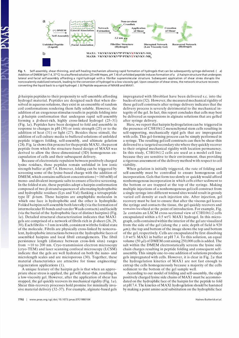
varied cell density at each injection site. After injection, gelrecovery must be fast to ensure that after the viscous gel leavesthe syringe and contacts the tissue, the gel quickly recovers andremains localized at the point of introduction. For example, Fig.2 a contains an LSCM cross-sectional view of C3H10t1/2 cellsencapsulated within a 0.5 wt% MAX1 hydrogel. In this micro-graph, cells contained within the interior of the gel are visualizedfrom the side of the gel (along the y axis; depth of field is 920m); the top and bottom of the image shows the top and bottomof the gel, respectively. Cells are encapsulated by first dissolving
1.0 wt% MAX1 in buffer at pH 7.4. To this solution, an equal volume (50 l) of DMEM containing 250,000 cells is added. Thesalt within the DMEM electrostatically screens the lysine sidechain charges resulting in peptide folding and consequent self-assembly. This simple one-to-one addition of solutions producesgels impregnated with cells. However, it is clear in Fig. 2 a thatthe hydrogelation kinetics of MAX1 are not fast enough toentrap the cells homogeneously because a majority of the cellssediment to the bottom of the gel sample well.
According to our model of folding and self-assembly, the eightpositively charged lysine side chains of MAX1 must be accommo-dated on the hydrophilic face of the hairpin for the peptide to foldat pH 7.4. The kinetics of MAX1 hydrogelation should be hastenedby making a point amino acid substitution on the hydrophilic face
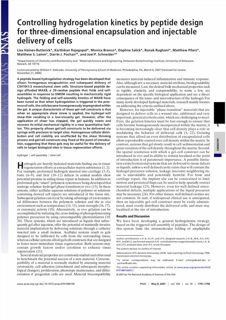
Fig. 1. Self-assembly, shear-thinning, and self-healing mechanism allowing rapid formation of hydrogels that can be subsequently syringe-delivered. ( a)
Addition of DMEM (pH 7.4, 37°C) to a buffered solution (25 mM Hepes, pH 7.4) of unfolded peptide induces formation of a -hairpin structure that undergoes
lateral and facial self-assembly affording a rigid hydrogel with a fibrillar supramolecular structure. Subsequent application of shear stress disrupts the
noncovalently stabilized network, leading to the conversion of hydrogel to a low-viscosity gel. Upon cessation of shear stress, the network structure recovers
converting the liquid back to a rigid hydrogel. (b) Peptide sequences of MAX8 and MAX1.
7792 www.pnas.orgcgidoi10.1073pnas.0701980104 Haines-Butterick et al.
8/3/2019 Lisa Haines-Butterick et al- Controlling hydrogelation kinetics by peptide design for three-dimensional encapsulation…
http://slidepdf.com/reader/full/lisa-haines-butterick-et-al-controlling-hydrogelation-kinetics-by-peptide 3/6
that lowers the overall charge density. By replacing the lysine sidechain at position 15 with a negatively charged side chain of glutamicacid, the overall peptide charge state is lowered by 2. The resultantpeptide, MAX8 (Fig. 1 b) has a lower amount of positive charge tobe screened and should fold and assemble much faster than MAX1in response to identical cell culture conditions. Apart from this, theMAX8 hairpin could possibly be stabilized by cross-strand saltbridge interactions between the glutamic acid and cross-strandlysine residues in the self-assembled state. Importantly, Fig. 2 bshows the LSCM image of a 0.5 wt% MAX8 hydrogel impregnated
with C3H10t1/2 mesenchymalstem cells, clearly illustrating that thekinetics of hydrogelation are optimal for a nearly homogeneousdistribution of cells; the depth of field (920 m) is identical to thatin Fig.2 a. The ability of MAX8 to homogeneously encapsulate cellsis consistent and reproducible and appears to be independent of celltype; additional encapsulation experiments using a separate lot of C3H10t1/2 mesenchymalstem cells as well as hepatocytes(Hep G2)are provided in the supporting information (SI).
To further investigate the influence of the peptide’s charge
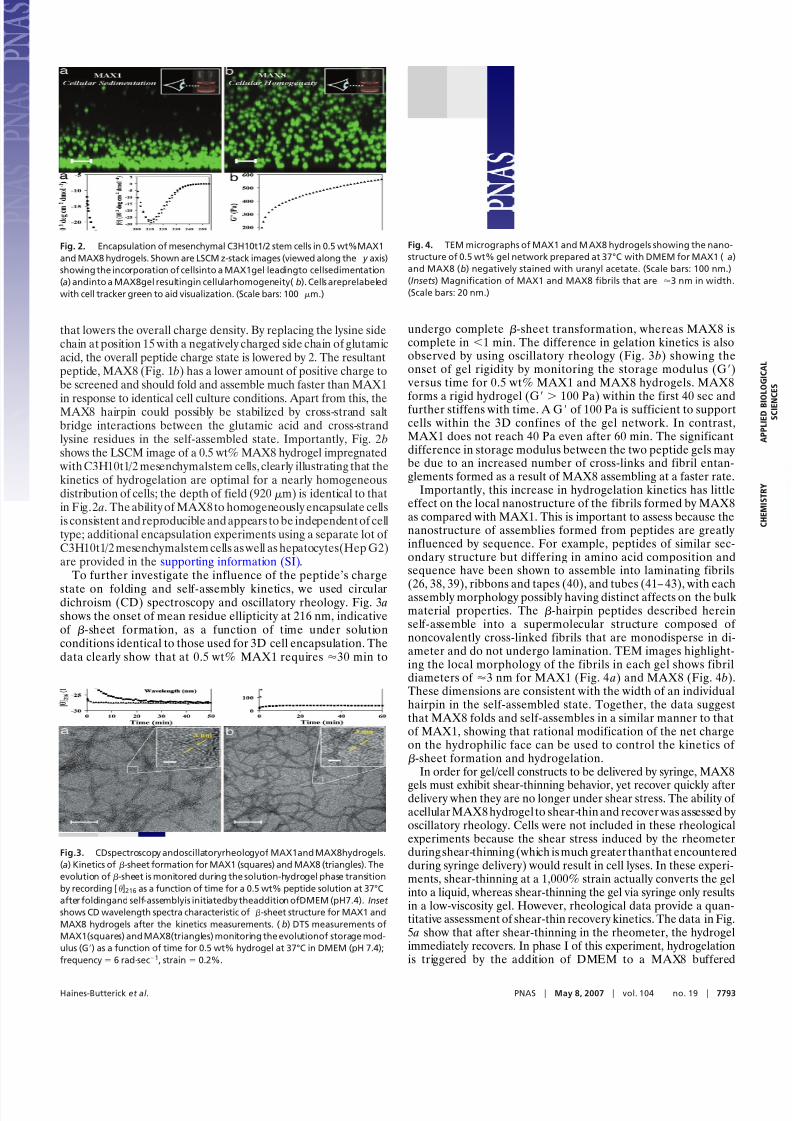
state on folding and self-assembly kinetics, we used circulardichroism (CD) spectroscopy and oscillatory rheology. Fig. 3 ashows the onset of mean residue ellipticity at 216 nm, indicativeof -sheet formation, as a function of time under solutionconditions identical to those used for 3D cell encapsulation. Thedata clearly show that at 0.5 wt% MAX1 requires 30 min to
undergo complete -sheet transformation, whereas MAX8 iscomplete in 1 min. The difference in gelation kinetics is alsoobserved by using oscillatory rheology (Fig. 3 b) showing theonset of gel rigidity by monitoring the storage modulus (G)
versus time for 0.5 wt% MAX1 and MAX8 hydrogels. MAX8
forms a rigid hydrogel (G 100 Pa) within the first 40 sec andfurther stiffens with time. A G of 100 Pa is sufficient to supportcells within the 3D confines of the gel network. In contrast,MAX1 does not reach 40 Pa even after 60 min. The significantdifference in storage modulus between the two peptide gels maybe due to an increased number of cross-links and fibril entan-glements formed as a result of MAX8 assembling at a faster rate.
Importantly, this increase in hydrogelation kinetics has littleeffect on the local nanostructure of the fibrils formed by MAX8as compared with MAX1. This is important to assess because thenanostructure of assemblies formed from peptides are greatlyinfluenced by sequence. For example, peptides of similar sec-ondary structure but differing in amino acid composition andsequence have been shown to assemble into laminating fibrils
(26, 38, 39), ribbons and tapes (40), and tubes (41– 43), with eachassembly morphology possibly having distinct affects on the bulkmaterial properties. The -hairpin peptides described hereinself-assemble into a supermolecular structure composed of noncovalently cross-linked fibrils that are monodisperse in di-ameter and do not undergo lamination. TEM images highlight-ing the local morphology of the fibrils in each gel shows fibrildiameters of 3 nm for MAX1 (Fig. 4 a) and MAX8 (Fig. 4 b).These dimensions are consistent with the width of an individualhairpin in the self-assembled state. Together, the data suggestthat MAX8 folds and self-assembles in a similar manner to thatof MAX1, showing that rational modification of the net chargeon the hydrophilic face can be used to control the kinetics of -sheet formation and hydrogelation.
In order for gel/cell constructs to be delivered by syringe, MAX8
gels must exhibit shear-thinning behavior, yet recover quickly afterdelivery when they are no longer under shear stress. The ability of acellular MAX8 hydrogel to shear-thin and recover was assessed byoscillatory rheology. Cells were not included in these rheologicalexperiments because the shear stress induced by the rheometerduringshear-thinning (which is much greater thanthat encounteredduring syringe delivery) would result in cell lyses. In these experi-ments, shear-thinning at a 1,000% strain actually converts the gelinto a liquid, whereas shear-thinning the gel via syringe only resultsin a low-viscosity gel. However, rheological data provide a quan-titative assessment of shear-thin recovery kinetics. The data in Fig.5 a show that after shear-thinning in the rheometer, the hydrogelimmediately recovers. In phase I of this experiment, hydrogelationis triggered by the addition of DMEM to a MAX8 buffered
Fig. 2. Encapsulation of mesenchymal C3H10t1/2 stem cells in 0.5 wt%MAX1
and MAX8 hydrogels. Shown are LSCM z-stack images (viewed along the y axis)
showing the incorporation of cellsinto a MAX1gel leadingto cellsedimentation
(a) andinto a MAX8gel resultingin cellularhomogeneity(b). Cells areprelabeled
with cell tracker green to aid visualization. (Scale bars: 100 m.)
Fig.3. CDspectroscopy andoscillatoryrheologyof MAX1and MAX8hydrogels.
(a) Kinetics of -sheet formation for MAX1 (squares) and MAX8 (triangles). The
evolution of-sheet is monitored during the solution-hydrogel phase transition
by recording [ ]216 as a function of time for a 0.5 wt% peptide solution at 37°C
after foldingand self-assemblyis initiatedby theaddition ofDMEM (pH7.4).Inset
shows CD wavelength spectra characteristic of -sheet structure for MAX1 and
MAX8 hydrogels after the kinetics measurements. (b) DTS measurements of
MAX1(squares) and MAX8(triangles) monitoring the evolutionof storage mod-
ulus (G) as a function of time for 0.5 wt% hydrogel at 37°C in DMEM (pH 7.4);
frequency 6 radsec1, strain 0.2%.
Fig. 4. TEM micrographs of MAX1 and M AX8 hydrogels showing the nano-
structure of 0.5 wt% gel network prepared at 37°C with DMEM for MAX1 (a)
and MAX8 (b) negatively stained with uranyl acetate. (Scale bars: 100 nm.)
(Insets) Magnification of MAX1 and MAX8 fibrils that are 3 nm in width.
(Scale bars: 20 nm.)
Haines-Butterick et al. PNAS May 8, 2007 vol. 104 no. 19 7793
8/3/2019 Lisa Haines-Butterick et al- Controlling hydrogelation kinetics by peptide design for three-dimensional encapsulation…
http://slidepdf.com/reader/full/lisa-haines-butterick-et-al-controlling-hydrogelation-kinetics-by-peptide 4/6
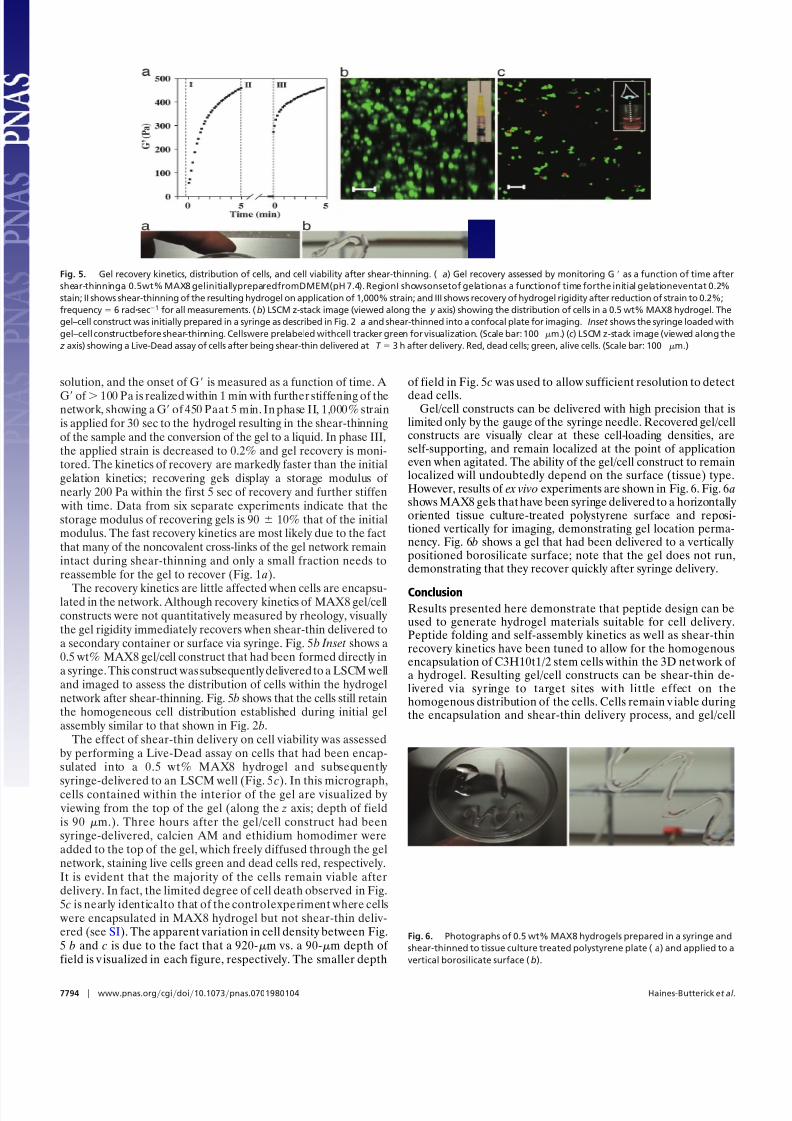
solution, and the onset of G is measured as a function of time. A
G of 100 Pa is realized within 1 min with further stiffening of thenetwork, showing a G of 450 Paat 5 min. In phase II, 1,000% strainis applied for 30 sec to the hydrogel resulting in the shear-thinningof the sample and the conversion of the gel to a liquid. In phase III,the applied strain is decreased to 0.2% and gel recovery is moni-tored. The kinetics of recovery are markedly faster than the initialgelation kinetics; recovering gels display a storage modulus of nearly 200 Pa within the first 5 sec of recovery and further stiffen
with time. Data from six separate experiments indicate that thestorage modulus of recovering gels is 90 10% that of the initialmodulus. The fast recovery kinetics are most likely due to the factthat many of the noncovalent cross-links of the gel network remainintact during shear-thinning and only a small fraction needs toreassemble for the gel to recover (Fig. 1 a).
The recovery kinetics are little affected when cells are encapsu-lated in the network. Although recovery kinetics of MAX8 gel/cellconstructs were not quantitatively measured by rheology, visuallythe gel rigidity immediately recovers when shear-thin delivered toa secondary container or surface via syringe. Fig. 5 b Inset shows a0.5 wt% MAX8 gel/cell construct that had been formed directly ina syringe. This construct was subsequentlydeliveredto a LSCM welland imaged to assess the distribution of cells within the hydrogelnetwork after shear-thinning. Fig. 5 b shows that the cells still retainthe homogeneous cell distribution established during initial gelassembly similar to that shown in Fig. 2 b.
The effect of shear-thin delivery on cell viability was assessedby performing a Live-Dead assay on cells that had been encap-sulated into a 0.5 wt% MAX8 hydrogel and subsequently
syringe-delivered to an LSCM well (Fig. 5 c). In this micrograph,cells contained within the interior of the gel are visualized by viewing from the top of the gel (along the z axis; depth of fieldis 90 m.). Three hours after the gel/cell construct had beensyringe-delivered, calcien AM and ethidium homodimer wereadded to the top of the gel, which freely diffused through the gelnetwork, staining live cells green and dead cells red, respectively.It is evident that the majority of the cells remain viable afterdelivery. In fact, the limited degree of cell death observed in Fig.5 c is nearly identicalto that of the controlexperiment where cells
were encapsulated in MAX8 hydrogel but not shear-thin deliv-ered (see SI). The apparent variation in cell density between Fig.5 b and c is due to the fact that a 920-m vs. a 90-m depth of field is v isualized in each figure, respectively. The smaller depth
of field in Fig. 5 c was used to allow sufficient resolution to detect
dead cells.Gel/cell constructs can be delivered with high precision that is
limited only by the gauge of the syringe needle. Recovered gel/cellconstructs are visually clear at these cell-loading densities, areself-supporting, and remain localized at the point of applicationeven when agitated. The ability of the gel/cell construct to remainlocalized will undoubtedly depend on the surface (tissue) type.However, results of ex vivo experiments are shown in Fig. 6. Fig. 6 ashows MAX8 gels thathave been syringe delivered to a horizontallyoriented tissue culture-treated polystyrene surface and reposi-tioned vertically for imaging, demonstrating gel location perma-nency. Fig. 6 b shows a gel that had been delivered to a verticallypositioned borosilicate surface; note that the gel does not run,demonstrating that they recover quickly after syringe delivery.
ConclusionResults presented here demonstrate that peptide design can beused to generate hydrogel materials suitable for cell delivery.Peptide folding and self-assembly kinetics as well as shear-thinrecovery kinetics have been tuned to allow for the homogenousencapsulation of C3H10t1/2 stem cells within the 3D network of a hydrogel. Resulting gel/cell constructs can be shear-thin de-livered via syringe to target sites with little effect on thehomogenous distribution of the cells. Cells remain v iable duringthe encapsulation and shear-thin delivery process, and gel/cell
Fig. 5. Gel recovery kinetics, distribution of cells, and cell viability after shear-thinning. ( a) Gel recovery assessed by monitoring G as a function of time after
shear-thinninga 0.5wt% MAX8 gelinitiallypreparedfromDMEM(pH 7.4). RegionI showsonsetof gelationas a functionof time forthe initial gelationeventat 0.2%
stain; II shows shear-thinning of the resulting hydrogel on application of 1,000% strain; and III shows recovery of hydrogel rigidity after reduction of strain to 0.2%;
frequency 6 radsec1 for all measurements. (b) LSCM z-stack image (viewed along the y axis) showing the distribution of cells in a 0.5 wt% MAX8 hydrogel. The
gel–cell construct was initially prepared in a syringe as described in Fig. 2 a and shear-thinned into a confocal plate for imaging. Inset shows the syringe loaded with
gel–cell constructbefore shear-thinning. Cellswere prelabeled withcell tracker green for visualization. (Scale bar: 100m.) (c) LSCM z-stack image (viewed along the
z axis) showing a Live-Dead assay of cells after being shear-thin delivered at T 3 h after delivery. Red, dead cells; green, alive cells. (Scale bar: 100 m.)
Fig. 6. Photographs of 0.5 wt% MAX8 hydrogels prepared in a syringe and
shear-thinned to tissue culture treated polystyrene plate (a) and applied to a
vertical borosilicate surface (b).
7794 www.pnas.orgcgidoi10.1073pnas.0701980104 Haines-Butterick et al.

8/3/2019 Lisa Haines-Butterick et al- Controlling hydrogelation kinetics by peptide design for three-dimensional encapsulation…
http://slidepdf.com/reader/full/lisa-haines-butterick-et-al-controlling-hydrogelation-kinetics-by-peptide 5/6
constructs stay fixed at the point of introduction, suggesting thatthese gels may be useful for the delivery of cells to targetbiological sites in tissue-regeneration efforts. More broadly, thisstudy suggest that peptide design can be used to control gelationkinetics and bulk material properties to address specific tech-nologies that demand materials with customized properties.
Materials and Methods
Hydrogel Preparation. Peptides were synthesized through Fmoc-
based solid phase peptide synthesis and purified to homogeneity asdescribed in detail in the SI. To a vial containing 1 mg of peptide,100 l of 25 mM Hepes (pH 7.4) was added resulting in a soluble1 wt% peptide solution. To this solution, an equal volume of DMEM supplemented with 25 mM Hepes (pH 7.4) was added toinitiate self-assembly, resulting in a 0.5 wt% hydrogel. All hydrogels
were prepared by this method unless otherwise stated.
CD. CD kinetic spectra were collected on a J-810 spectropola-rimeter (Jasco, Tokyo, Japan) employing 0.1 mm quartz water-
jacketed cell. Peptide samples were prepared as described aboveand transferred to the cell at 37°C. The ellipticity in millidegrees
were monitored at 216 nm as a function of time. After the kineticmeasurement, a wavelength scan was recorded at 37°C using a2-nm step size. The concentrations of MAX1 and MAX8 stock
solutions were determined by absorbance (220 15,750cm1
M1) after dilution with water. Mean residue ellipticity[ ] ( obs /10 l c)/ r , where obs is the measured ellipticity inmillidegrees, l is the length of the cell (in cm), c is the concen-tration (in M), and r is the number of residues.
Oscillatory Rheology. Oscillatory rheology experiments were per-formed on a rheometer (AR 2000; TA Instruments, New Castle,DE) with a 25-mm-diameter stainless steel parallel plate geom-etry with a gap height of 0.5 mm. All measurements wereacquired at 37°C. For dynamic time sweeps (DTS) the hydrogels
were prepared as described above and quickly transferred to therheometer where the storage modulus (G) was monitored as afunction of time; frequency 6 radsec1 and strain 0.2%. Fortheshear-thinning experiments, a DTS was preformed for 10 minat which time 1,000% stain was applied for 30 sec to shear-thinthe material. Then, the strain was decreased to 0.2% and Gmonitored as a function of time. Dynamic frequency, dynamic
strain, and DTS measurements measuring both G and the lossmodulus (G) are provided in SI.
TEM. Hydrogels were prepared as described above for TEM exper-iments. A small volume of diluted gel (2–5 l) solution was appliedto carbon-coated copper grids. Samples were negatively stained
with 2% (wt/vol) aqueous uranyl acetate. Bright field images of thefibril nanostructure were taken on a 1000-FX transmission electronmicroscope (JEOL, Tokyo, Japan) at 200 kV accelerating voltage
on a CCD camera (Gatan, Pleasanton, CA).
Cell Culture and Confocal Microscopy. C3H10t1/2 cell growthconditions were 90% DMEM supplemented with 25 mMHepes, 10% FBS, 5 mM L-glutamine, and 50 g/ml Gentamicinat 37°C in 5% CO2. For confocal micrographs of hydrogelsimpregnated with prelabeled cells, a suspension of 1.5 106
cells per ml were incubated in a solution of 5 M cell trackergreen in DMEM for 45 min. After labeling, cells were washedthree times with PBS and resuspended in DMEM at a con-centration of 5 106 cells per ml. An equal volume of the cellsuspension was added to a vial containing a solution of buffered peptide in 25 mM Hepes (pH 7.4); the resultingsolution was immediately transferred to an eight-well boro-silicate confocal plate and placed into the incubator at 37°C
and 5% CO2
. For shear-thinning experiments, the gel/cellconstructs were prepared as above and immediately loadedinto a 1-ml syringe equipped with a 20-gauge needle andallowed to undergo hydrogelation for 5 min before shear-thinning onto a confocal plate for imaging. For viabilitystudies, the gel/cell constructs were prepared as above withunlabeled cells. Viability of encapsulated cells in 0.5 wt%hydrogels (before and after shear-thinning) was assessed byusing a Live/Dead assay at 3 h after encapsulation. A stocksolution containing both 1 M calcein AM and 2 M ethidiumhomodimer in DMEM were prepared according to the Live-Dead assay (Molecular Probes # L3224) package instructions,and 200 l of this stock was added to each well. All gel/cellconstructs were imaged by using 10 magnification on a 510LSCM microscope (Zeiss, Jena, Germany).
This work was supported by National Institutes of Health Grant R01DE016386-01. Teacher-Scholar M.P. was supported by National ScienceFoundation Grant CHE0348323.
1. Lee KY, Mooney DJ (2001) Chem Rev 101:1869–1879.2. Peppas NA, Huang Y, Torres-Lugo M, Ward JH, Zhang J (2000) Annu Rev
Biomed Eng 2:9–29.3. Freed LE, Marquis JC, Nohria A, Emmanual J, Mikos AG, Langer R (1993)
J Biomed Mater Res 27:11–23.4. Ponticiello MS, Schinagl RM, Kadiyala S, Barry FP (2000) J Biomed Mater Res
52:246–255.5. Bryant SJ, Durand KL, Anseth KS (2003) J Biomed Mater Res Part A
67A:1430–1436.6. Schmoekel HG, Weber FE, Schense JC, Gratz KW, Schawalder P, Hubbell JA
(2005) Biotechnol Bioeng 89:253–262.7. Simmons CA, Alsberg E, Hsiong S, Kim WJ, Mooney DJ (2004) Bone 35:562–569.8. Holland TA, Bodde EWH, Baggett LS, Tabata Y, Mikos AG, Jansen JA (2005)
J Biomed Mater Res Part A 75A:156–167.9. Yamamoto M, Takahashi Y, Tabata Y (2006) Tissue Eng 12:1305–1311.
10. Hammond JS, Beckingham IJ, Shakesheff KM (2006) Exp Rev Med Devices 3:21–27.11. Takimoto Y, Dixit V, Arthur M, Gitnick G (2003) Cell Transplant 12:413–421.12. Bruns H, Kneser U, Holzhuter S, Roth B, Kluth J, Kaufmann PM, Kluth D,
Fiegel HC (2005) Tissue Eng 11:1718–1726.13. Elisseeff J (2004) Exp Opin Biological Ther 4:1849–1859.14. Jeong B, Bae YH, Lee DS, Kim SW (1997) Nature 388:860–862.15. Huh KM, Bae YH (1999) Polymer 40:6147–6155.16. Bhatia SR, Khattak SF, Roberts SC (2005) Curr Opin Colloid Interface Sci 10:45–51.17. Oerther S, Le Gall H, Payan E, Lapicque F, Presle N, Hubert P, Dexheimer
J, Netter P (1999) Biotechnol Bioeng 63:206–215.18. Collier JH, Messersmith PB (2003) Bioconjug Chem 14:748–755.19. Bryant SJ, Nuttelman CR, Anseth KS (2000) J Biomater Sci Polym Ed 11:439–457.20. Nguyen KT, West JL (2002) Biomaterials 23:4307–4314.
21. Tabata Y (2003) Tissue Eng 9:S5–S15.
22. Dvir-Ginzberg M, Gamlieli-Bonshtein I, Agbaria R, Cohen S (2003) Tissue Eng
9:757–766.
23. Chang CH, Kuo TF, Lin CC, Chou CH, Chen KH, Lin FH, Liu HC (2006)
Biomaterials 27:1876–1888.
24. Hoemann CD, Sun J, Legare A, McKee MD, Buschmann MD (2005) Osteo-
arthritis Cartilage 13:318–329.
25. Ozbas B, Kretsinger J, Rajagopal K, Schneider JP, Pochan DJ (2004) Macro-
molecules 37:7331–7337.
26. Rajagopal K, Ozbas B, Pochan DJ, Schneider JP (2006) Eur Biophys J Biophys
Lett 35:162–169.
27. Haines LA, Rajagopal K, Ozbas B, Salick DA, Pochan DJ, Schneider JP (2005) J Am Chem Soc 127:17025–17029.
28. Kretsinger JK, Haines LA, Ozbas B, Pochan DJ, Schneider JP (2005) Bioma-
terials 26:5177–5186.
29. Ozbas B, Rajagopal K, Schneider JP, Pochan DJ (2004) Phys Rev Lett 93:268106.
30. Schneider JP, Pochan DJ, Ozbas B, Rajagopal K, Pakstis L, Kretsinger J (2002)
J Am Chem Soc 124:15030–15037.
31. Pochan DJ, Schneider JP, Kretsinger J, Ozbas B, Rajagopal K, Haines L (2003)
J Am Chem Soc 125:11802–11803.
32. Marler JJ, Guha A, Rowley J, Koka R, Mooney D, Upton J, Vacanti JP (2000)
Plast Reconstr Surg 105:2049–2058.
33. Cao YL, Rodriguez A, Vacanti M, Ibarra C, Arevalo C, Vacanti CA (1998)
J Biomater Sci Polym Ed 9:475–487.
34. Park DJ, Choi BH, Zhu SJ, Huh JY, Kim BY, Lee SH (2005) J Cranio-
Maxillofacial Surg 33:50–54.
35. Ramachandran S, Tseng Y, Yu YB (2005) Biomacromolecules 6:1316–1321.
Haines-Butterick et al. PNAS May 8, 2007 vol. 104 no. 19 7795

8/3/2019 Lisa Haines-Butterick et al- Controlling hydrogelation kinetics by peptide design for three-dimensional encapsulation…
http://slidepdf.com/reader/full/lisa-haines-butterick-et-al-controlling-hydrogelation-kinetics-by-peptide 6/6
36. Huin-Amargier C, Marchal P, Payan E, Netter P, Dellacherie E (2006) J Biomed Mater Res Part A 76A:416–424.
37. Davis ME, Motion JPM, Narmoneva DA, Takahashi T, Hakuno D, Kamm RD,Zhang SG, Lee RT (2005) Circulation 111:442–450.
38. Lamm MS, Rajagopal K, Schneider JP, Pochan DJ (2005) J Am Chem Soc
127:16692–16700.39. de la Paz ML, Goldie K, Zurdo J, Lacroix E, Dobson CM, Hoenger A, Serrano
L (2002) Proc Natl Acad Sci USA 99:16052–16057.
40. Aggeli A, Nyrkova IA, Bell M, Harding R, Carrick L, McLeish TCB,Semenov AN, Boden N (2001) Proc Natl Acad Sci USA 98:11857–11862.
41. Lu K, Jacob J, Thiyagarajan P, Conticello VP, Lynn DG (2003) J Am Chem Soc
125:6391–6393.42. Reches M, Gazit E (2004) Nano Lett 4:581–585.43. Vauthey S, Santoso S, Gong HY, Watson N, Zhang SG (2002) Proc Natl Acad
Sci USA 99:5355–5360.
7796 www.pnas.orgcgidoi10.1073pnas.0701980104 Haines-Butterick et al.