liquid membranes for gas vapor separations.pdf
TRANSCRIPT

8/10/2019 Liquid membranes for gas vapor separations.pdf
http://slidepdf.com/reader/full/liquid-membranes-for-gas-vapor-separationspdf 1/11
Journal of Membrane Science 325 (2008) 509–519
Contents lists available at ScienceDirect
Journal of Membrane Science
j o u r n a l h o m e p a g e : w w w . e l s e v i e r . c o m / l o c a t e / m e m s c i
Review article
Liquid membranes for gas/vapor separations
F.F. Krull∗, C. Fritzmann, T. Melin
Aachener Verfahrenstechnik, Chemical Reaction Engineering, RWTH Aachen University, Turmstr. 46, 52056 Aachen, Germany
a r t i c l e i n f o
Article history:
Received 16 July 2008
Received in revised form
10 September 2008
Accepted 11 September 2008
Available online 19 September 2008
Keywords:
Immobilized liquid membrane
Supported liquid membrane
Gas separation
Vapor separation
Preparation
Performance
Materials
a b s t r a c t
A review on developments of liquid membranes (LMs) in the field of gas and vapor separation of the
last 16 years is presented. Liquid membrane configurations employing supports, i.e. immobilized, sup-
portedandcontainedliquidmembranesare focussedand detailedinformationon therespectivematerials,i.e. supports (supplier, type, thickness, pore width, porosity, tortuosity), liquids and carriers, are pre-
sented togetherwith theirspecific separation tasks. Performance of differentLMs in termsof permeability
and selectivity as well as stability (duration of testing, applied differential pressures) are compared and
discussed. Finally, different preparation methods of LMs are illustrated.
© 2008 Elsevier B.V. All rights reserved.
Contents
1. Introduction . . . . . . . . . . . . . . . . . . . . . . . . . . . . . . . . . . . . . . . . . . . . . . . . . . . . . . . . . . . . . . . . . . . . . . . . . . . . . . . . . . . . . . . . . . . . . . . . . . . . . . . . . . . . . . . . . . . . . . . . . . . . . . . . . . . . . . . . . 509
2. Liquid membrane configurations . . . . . . . . . . . . . . . . . . . . . . . . . . . . . . . . . . . . . . . . . . . . . . . . . . . . . . . . . . . . . . . . . . . . . . . . . . . . . . . . . . . . . . . . . . . . . . . . . . . . . . . . . . . . . . . . . . . 510
3. Mass transfer in liquid membranes . . . . . . . . . . . . . . . . . . . . . . . . . . . . . . . . . . . . . . . . . . . . . . . . . . . . . . . . . . . . . . . . . . . . . . . . . . . . . . . . . . . . . . . . . . . . . . . . . . . . . . . . . . . . . . . . . 510
4. Materials for LM . . . . . . . . . . . . . . . . . . . . . . . . . . . . . . . . . . . . . . . . . . . . . . . . . . . . . . . . . . . . . . . . . . . . . . . . . . . . . . . . . . . . . . . . . . . . . . . . . . . . . . . . . . . . . . . . . . . . . . . . . . . . . . . . . . . . . 511
4.1. Supports for LM . . . . . . . . . . . . . . . . . . . . . . . . . . . . . . . . . . . . . . . . . . . . . . . . . . . . . . . . . . . . . . . . . . . . . . . . . . . . . . . . . . . . . . . . . . . . . . . . . . . . . . . . . . . . . . . . . . . . . . . . . . . . . . 511
4.2. Liquids and carriers for LM . . . . . . . . . . . . . . . . . . . . . . . . . . . . . . . . . . . . . . . . . . . . . . . . . . . . . . . . . . . . . . . . . . . . . . . . . . . . . . . . . . . . . . . . . . . . . . . . . . . . . . . . . . . . . . . . . . 513
5. Performance of LM . . . . . . . . . . . . . . . . . . . . . . . . . . . . . . . . . . . . . . . . . . . . . . . . . . . . . . . . . . . . . . . . . . . . . . . . . . . . . . . . . . . . . . . . . . . . . . . . . . . . . . . . . . . . . . . . . . . . . . . . . . . . . . . . . . 515
6. Preparation of LM . . . . . . . . . . . . . . . . . . . . . . . . . . . . . . . . . . . . . . . . . . . . . . . . . . . . . . . . . . . . . . . . . . . . . . . . . . . . . . . . . . . . . . . . . . . . . . . . . . . . . . . . . . . . . . . . . . . . . . . . . . . . . . . . . . . 517
7. Summary of liquid membrane review . . . . . . . . . . . . . . . . . . . . . . . . . . . . . . . . . . . . . . . . . . . . . . . . . . . . . . . . . . . . . . . . . . . . . . . . . . . . . . . . . . . . . . . . . . . . . . . . . . . . . . . . . . . . . . 518
Acknowledgements . . . . . . . . . . . . . . . . . . . . . . . . . . . . . . . . . . . . . . . . . . . . . . . . . . . . . . . . . . . . . . . . . . . . . . . . . . . . . . . . . . . . . . . . . . . . . . . . . . . . . . . . . . . . . . . . . . . . . . . . . . . . . . . . . 518
References . . . . . . . . . . . . . . . . . . . . . . . . . . . . . . . . . . . . . . . . . . . . . . . . . . . . . . . . . . . . . . . . . . . . . . . . . . . . . . . . . . . . . . . . . . . . . . . . . . . . . . . . . . . . . . . . . . . . . . . . . . . . . . . . . . . . . . . . . . . 518
Abbreviations: BEHA, bis(2-ethylhexyl)amine; CA, carbonic anhydrase; CAN,cel-lulose acetate-nitrate; CLM, contained liquid membrane; CUN, cuprophan; DAE,
diaminoethane; DBC, dibenzo-18-crown-6; DEA, diethanolamine; DETA, diethylen-
etriamine; DEYA, diethylamine; DGA, diglycolamine; DIPA, diisopropanolamine;
EDA, ethylenediamine; ELM, emulsion liquid membrane; FS, flat sheet; HF, hollow
fiber; IL,ionic liquid;ILM, immobilized liquid membrane; LiAlO2, lithium aluminate;
LM,liquidmembrane; MEA,monoethanolamine;MS, molten salt; NA,not available;
PAA, porous anodic alumina; PAMAM, polyamidoamine dendrimer; PAN, poly-
acrylonitrile; PEG, polyethyleneglycol; PES, polyethersulfone; PP, polypropylene;
PS, polysulfone; PTMSP, polytrimethylsilylpropyne; PVDF, polyvinylidinedifluoride;
SLM, supported liquid membrane; TEG, triethyleneglycol.∗ Corresponding author. Tel.: +49 241 8 09 05 83; fax: +49 241 8 09 22 52.
E-mail addresses: [email protected] (F.F. Krull),
[email protected] (C. Fritzmann),
[email protected] (T. Melin).
1. Introduction
For more than 30 years now, liquid membranes have been in
focus of research. Since diffusivities in liquids in comparison to
solids are higher by several orders of magnitude, enhanced per-
meabilities of liquid in comparison to solid membranes can be
expected.
Investigated applications of liquid membranes comprise the
separation/concentration of ions [1,2], the separation of liquid feeds
[3] and the separation of gases or vapors which are subject of the
review at hand.
Several reviews have been written on liquid membrane-based
separations [4–9]. However, to our knowledge only one of these
0376-7388/$ – see front matter © 2008 Elsevier B.V. All rights reserved.
doi:10.1016/j.memsci.2008.09.018

8/10/2019 Liquid membranes for gas vapor separations.pdf
http://slidepdf.com/reader/full/liquid-membranes-for-gas-vapor-separationspdf 2/11
510 F.F. Krull et al. / Journal of Membrane Science 325 (2008) 509–519
reviews by Dutta et al. written in 1992 is explicitly and only
concerned with gas and vapor separation by means of liquid mem-
branes [10]. Thus, a review on developments of liquid membranes
forgas andvapor separationscoveringthe last 16 yearsis presented
here.
After presenting possible LM configurations (Section 2), the
mass transfer mechanism in LM will be briefly discussed (Section
3). The core of the review at hand is then given by the literature
review of the last 16 years on LMs employed for gas or vapor sep-
arations. In Section 4, LM configurations and detailed information
on the respective materials, i.e. supports (supplier, type, thickness,
pore width, porosity, tortuosity), liquids and carriers, will be pre-
sented togetherwith theirspecificseparation tasks.In Section 5, the
performance of different LMs in terms of permeability and selec-
tivity as well as stability (duration of testing, applied differential
pressures) will be compared and discussed. Finally, in Section 6,
different preparation methods of LMs will be illustrated.
2. Liquid membrane configurations
Generally, liquid membranes with and without supports can be
differentiated.For thosenot employing supports, the so-called bulkliquid membranes (BLM) and emulsion liquid membranes (ELM)
arefound. The liquid membranesemploying a support can be subdi-
vided into immobilized liquid membranes (ILM), supported liquid
membranes (SLM) and contained liquid membranes (CLM) (Fig. 1).
The simplest form of liquid membrane without support is given
by the BLM consisting of a u-tube and three non-miscible liquids.
BLM are mainly used to study mass transfer from the donor phase
through the membrane phase into the acceptor phase but do not
have any relevancefor large-scale separation processes due to their
large thickness.
In principle, ELM represent a double emulsion consisting of an
acceptor phase being dispersed in a membrane phase and this
emulsion again being dispersed in a donor phase. A species from
the donor phase is absorbed into the membrane phase, diffuses
towards the acceptor phase and finally is desorbed into the latter.
To obtain the permeate, the double emulsion is disintegrated and
the species is extracted from the acceptor phase.
For liquid membranes employing supports, the most compact
form of a LM is given by an ILM where a liquid is held inside the
pores of a porous support (e.g. a porous solid membrane) by means
of capillary forces. The support has to be wettable by the liquid
for this configuration. If the support is not wetted by the liquid, a
SLM can be prepared where a liquid is located on top of the porous
support. The CLM represents a SLM with two porous supports on
both sides. This configuration offers the possibility of replenish-
ing or regenerating the membrane phase during operation. Thus
a breakdown of the membrane function caused by evaporation of
the membrane liquid can be avoided by means of continuous liq-
uid replenishment. As to stability of LM configurations employing
supports, further requirements will be discussed in more detail in
the following sections. In terms of mass transfer, the LM employ-
ing supports work according to the same principles as the ELM,
i.e. a solution-diffusion mechanism, which will be explained in the
following Section 3.
In the literature the terms SLM, ILM and CLM are often mixed
up or assigned to different liquid membraneconfigurations. Mostly,
the term supported liquid membrane is used for the liquid mem-
brane configuration where the membrane liquid is situated within
the support corresponding to an immobilized liquid membrane
according to the classification given in Fig.1. However, regardless of
what an author in theliterature names a configuration andwhether
that naming fits the classification given above, all naming of liq-
uid membrane configurations in the work at hand is done to the
classification given in Fig. 1.
The review at hand exclusively concerns liquid membranes
employing supports used for gas and vapor separation applications.
In the following, the term liquid membrane is used as synonym for
liquid membranes employing supports.
3. Mass transfer in liquid membranes
Liquid membranes work according to a solution-diffusion mass
transfer mechanism as do dense solid membranes. Including the
mass transfer steps in the respective feed and permeate phases, a
gas molecule is transported across the membrane in seven steps:
(1) Convective transport of the molecule towards the membrane.
(2) Diffusion of the molecule through the boundary layer at thefeed–membrane interface.
(3) Absorption into the membrane phase.
(4) Diffusion through the liquid membrane.
(5) Desorption into the permeate phase.
(6) Diffusion of the molecule through the boundary layer at the
permeate–membrane interface.
Fig. 1. Liquid membrane configurations.

8/10/2019 Liquid membranes for gas vapor separations.pdf
http://slidepdf.com/reader/full/liquid-membranes-for-gas-vapor-separationspdf 3/11
F.F. Krull et al. / Journal of Membrane Science 325 (2008) 509–519 511
Fig. 2. Facilitated transport ILM.
(7) Convective transport of the molecule into the permeate
phase.
The actual solution-diffusion mechanism is given by the steps
3–5 only.
Given the assumption of similar diffusivities of two gases in a
liquid, the selectivity of a liquidmembrane is based on the sorption
selectivity between the two gases in the feed phase. In case this
sorption selectivity is very low or lacking, carrier species may be
employed (Fig. 2).
A molecule of the preferred gas is reversibly bound by a car-
rier and transported across the membrane either via diffusion
of the carrier–molecule complex or via a hopping mechanism
of the molecule from one carrier to another [8,11–14]. At the
permeate–membrane interface, the molecule dissociates from the
carrier and is desorbed into the permeate phase. This transport
mechanism is often called facilitated transport.
In the case of facilitated transport, the selectivity of a sep-
aration is mainly influenced by the availability of free carriermolecules. On the one hand, the solubility of carrier molecules
in the membrane phase is limited. On the other hand, the mobil-
ity of the carrier molecules and the formed complexes determine
the number of free carrier molecules at the feed–membrane inter-
face. As long as free carrier molecules are available, the flux
across the membrane increases non-linearly with increasing driv-
ing force across the membrane. From the point where diffusion
of unsaturated carriers towards the feed–membrane interphase
and diffusion of saturated carriers from the feed–membrane inter-
phase become the limiting steps in the solution-diffusion process,
i.e. the chemisorption and diffusion process, the flux increases
due to the seizure of facilitated transport. However, superim-
posed physical diffusion might lead to a linear increase with
increasing driving force. At given transport of undesired speciesby means of physical diffusion, the selectivity of a membrane
also increases non-linearly up to the point of full carrier sat-
uration at the feed–membrane interface. Due to the very low
diffusive flux of undesired species at low concentration differ-
ence across the membrane, selectivity shows maximum values
within the range from zero to full carrier saturation concen-
tration difference across the membrane. From the point of full
carrier saturation at the feed–membrane interphase, selectivity
might either show constant values (ratio of physical diffusion
between desired and undesired species stays constant) or even
decrease independent of the applied gas-concentration differ-
ence across the membrane (enhanced diffusive flux of undesired
species in contrast to slightly or non-enhanced flux of the desired
species).
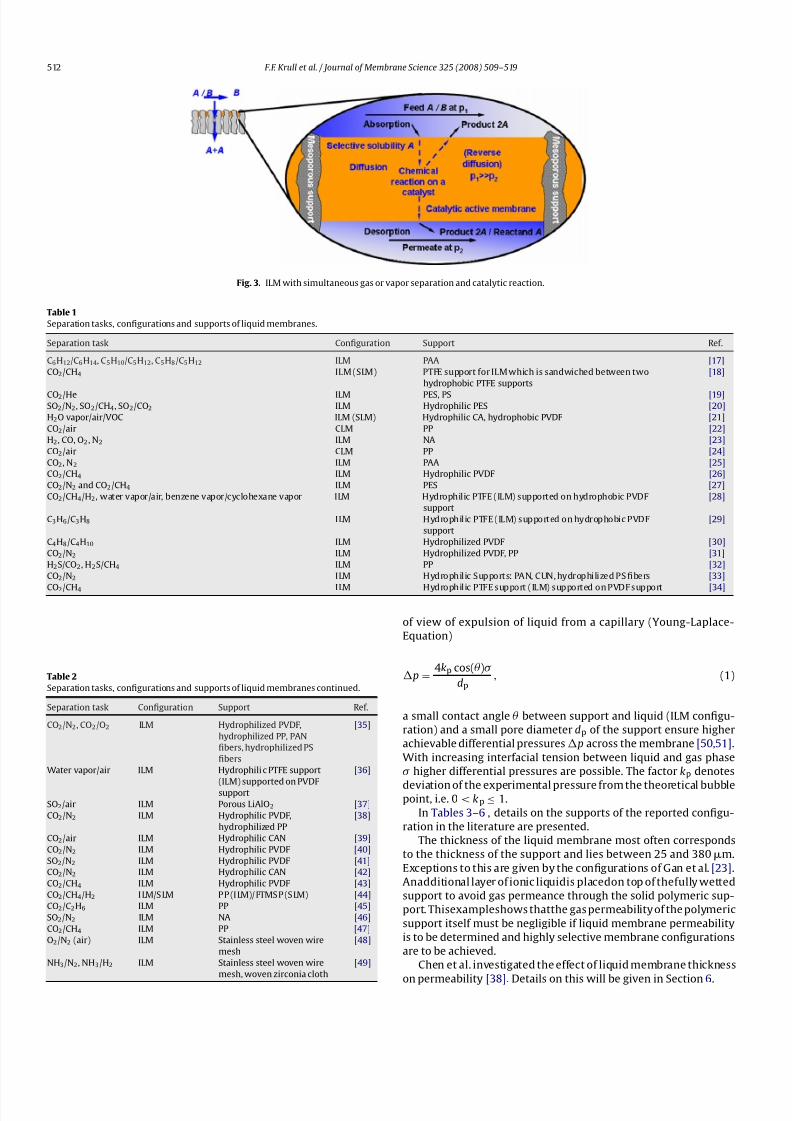
A different approach to increase or obtain a sorption selectiv-
ity of the membrane liquid is given by the use of homogeneous
catalysts (Fig. 3).
In contrast to a carrier, the catalyst increases the solubility of a
gas inside the membrane liquid due to conversion of the gas to aproduct, which diffuses towards the permeate phase. However, in
this case a back-diffusion of reaction products cannot be excluded
since the partial pressure for the product in the gas phases is very
low at both sides of the membrane.
The combination of the unit operations homogeneous catalysis
and gas separation into one clearly leads to process integration.
To present, homogeneous catalysis inside an ILM has only been
investigated by Carlin et al. [15,16].
4. Materials for LM
As in every membrane process, separation characteristics of the
process are determined by the properties of the membrane mate-
rial. Hence, the materials of LM, i.e. liquids and carriers as well asthe supports are subject of the Sections 4.2 and 4.1, respectively.
4.1. Supports for LM
As shown in Section 3, the liquid and carriers are responsible
for LM properties in terms of permeability and selectivity, while
the choice of the support merely affects the permeability by its
porosity. However, the right choice of support ensures sufficient
stability of the LM configuration.
In Tables 1 and 2 the separation tasks, configurations and
employed supports reported in the literature of the last 16 years
are given chronologically, starting with the most recently reported
configuration.
As can be seen from Tables 1 and 2, the vast majority of sup-ports are flat sheet polymeric supports. Only some authors employ
polymeric hollow fiber supports [22,24,33,35] andHuanget al. and
Baltus et al. employ a ceramic support [17,25].
For preparation of an ILM, the support must be wettable by the
membrane liquid whereas it should be non-wettable for prepa-
ration of an SLM. Further, the support should be chemically and
thermallyinert to avoida mechanical breakdown of the membrane
function. Wettability is ensured if hydrophobic supports are com-
bined with organic liquids or hydrophilic liquids with hydrophilic
supports. The latter represents the majority in the reported config-
urations.
The support mainly influences the mechanical and long-term
stability of a LM configuration. According to the so-called bubble
point equation, which is derived from a thermodynamical point
8/10/2019 Liquid membranes for gas vapor separations.pdf
http://slidepdf.com/reader/full/liquid-membranes-for-gas-vapor-separationspdf 4/11
512 F.F. Krull et al. / Journal of Membrane Science 325 (2008) 509–519
Fig. 3. ILM with simultaneous gas or vapor separation and catalytic reaction.
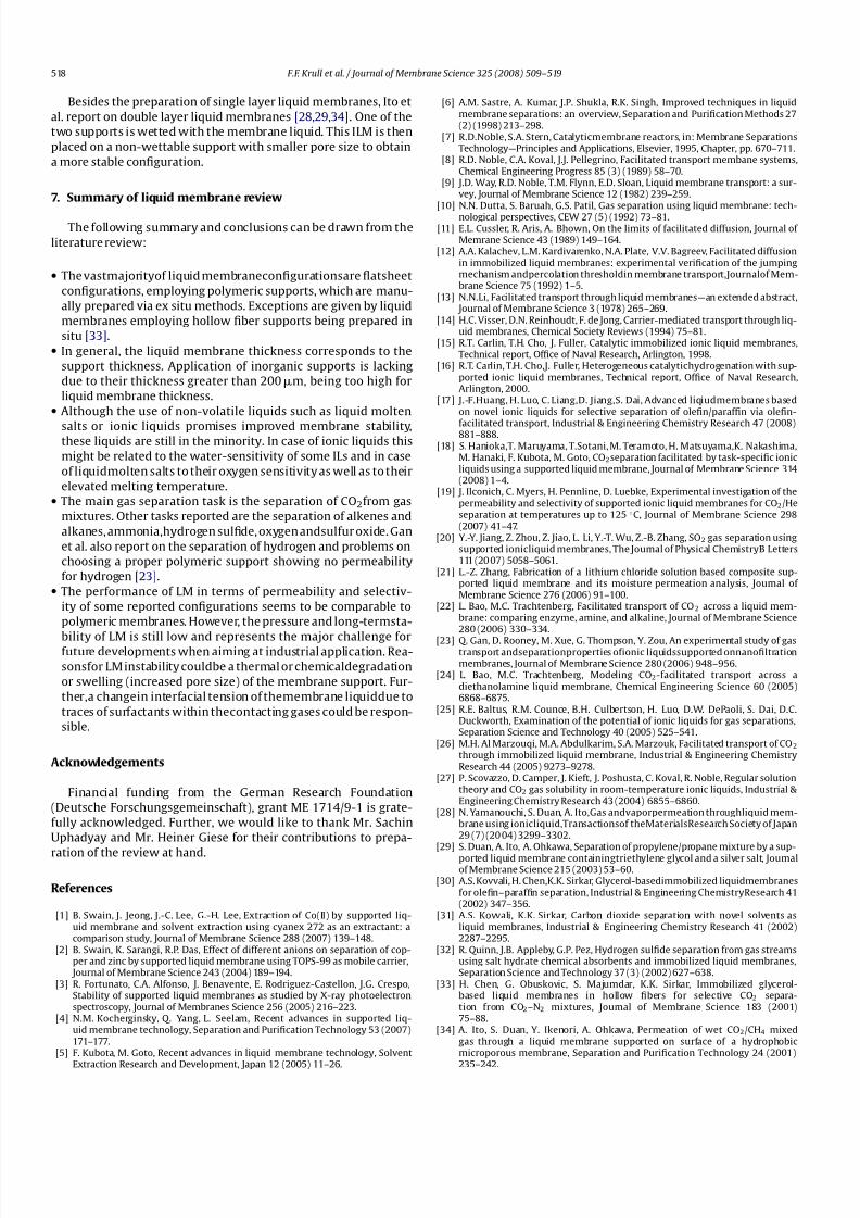
Table 1
Separation tasks, configurations and supports of liquid membranes.
Separation task Configuration Support Ref.
C6H12/C6 H14, C5H10/C5H12, C5H8/C5H12 ILM PAA [17]
CO2/CH4 ILM (SLM) PTFE support for ILM which is sandwiched between two
hydrophobic PTFE supports
[18]
CO2/He ILM PES, PS [19]SO2/N2, SO2/CH4, SO2/CO2 ILM Hydrophilic PES [20]
H2O vapor/air/VOC ILM (SLM) Hydrophilic CA, hydrophobic PVDF [21]
CO2/air CLM PP [22]
H2, CO, O2 , N2 ILM NA [23]
CO2/air CLM PP [24]
CO2, N2 ILM PAA [25]
CO2/CH4 ILM Hydrophilic PVDF [26]
CO2/N2 and CO2/CH4 ILM PES [27]
CO2/CH4/H2, water vapor/air, benzene vapor/cyclohexane vapor ILM Hydrophilic PTFE (ILM) supported on hydrophobic PVDF
support
[28]
C3H6/C3H8 ILM Hydrophilic PTFE (ILM) supported on hydrophobic PVDF
support
[29]
C4H8/C4H10 ILM Hydrophilized PVDF [30]
CO2/N2 ILM Hydrophilized PVDF, PP [31]
H2S/CO2, H2S/CH4 ILM PP [32]
CO2/N2 ILM Hydrophilic Supports: PAN, CUN, hydrophilized PS fibers [33]
CO2/CH4 ILM Hydrophilic PTFE support (ILM) supported on PVDF support [34]
Table 2
Separation tasks, configurations and supports of liquid membranes continued.
Separation task Configuration Support Ref.
CO2/N2, CO2/O2 ILM Hydrophilized PVDF,
hydrophilized PP, PAN
fibers, hydrophilized PS
fibers
[35]
Water vapor/air ILM Hydrophili c PTFE support
(ILM) supported on PVDFsupport
[36]
SO2/air ILM Porous LiAlO2 [37]
CO2/N2 ILM Hydrophilic PVDF,
hydrophilized PP
[38]
CO2/air ILM Hydrophilic CAN [39]
CO2/N2 ILM Hydrophilic PVDF [40]
SO2/N2 ILM Hydrophilic PVDF [41]
CO2/N2 ILM Hydrophilic CAN [42]
CO2/CH4 ILM Hydrophilic PVDF [43]
CO2/CH4/H2 I LM/S LM P P (I LM)/ PTMS P (S LM) [44]
CO2/C2H6 ILM PP [45]
SO2/N2 ILM NA [46]
CO2/CH4 ILM PP [47]
O2/N2 (air) ILM Stainless steel woven wire
mesh
[48]
NH3/N2, NH3/H2 ILM Stainless steel woven wire
mesh, woven zirconia cloth
[49]
of view of expulsion of liquid from a capillary (Young-Laplace-
Equation)
p =4kp cos( )
dp, (1)
a small contact angle between support and liquid (ILM configu-
ration) and a small pore diameter dp of the support ensure higher
achievable differential pressures p across the membrane [50,51].
With increasing interfacial tension between liquid and gas phase
higher differential pressures are possible. The factor kp denotes
deviation of the experimental pressure from the theoretical bubblepoint, i.e. 0 < kp ≤ 1.
In Tables 3–6 , details on the supports of the reported configu-
ration in the literature are presented.
The thickness of the liquid membrane most often corresponds
to the thickness of the support and lies between 25 and 380 m.
Exceptions to this are given by the configurations of Gan et al. [23].
Anadditional layer of ionic liquidis placedon top of thefully wetted
support to avoid gas permeance through the solid polymeric sup-
port. Thisexampleshows thatthe gas permeability of the polymeric
support itself must be negligible if liquid membrane permeability
is to be determined and highly selective membrane configurations
are to be achieved.
Chen et al. investigated the effect of liquid membrane thickness
on permeability [38]. Details on this will be given in Section 6.

8/10/2019 Liquid membranes for gas vapor separations.pdf
http://slidepdf.com/reader/full/liquid-membranes-for-gas-vapor-separationspdf 5/11
F.F. Krull et al. / Journal of Membrane Science 325 (2008) 509–519 513
Table 3
Supports for liquid membranes.
Support material Supplier/type Shape Thickness [m] Ref.
PAA Whatman FS 60 [17]
PTFE support for ILM which is
sandwiched between two
hydrophobic PTFE supports
NA FS 35 [18]
PS, PES Pall, HT Tuffryn (PS), Supor (PES) FS 152 (PS), 145 (PES) [19]
Hydrophilic PES NA FS 150 [20]Hydrophilic CA, Hydrophobic PVDF NA FS 52 (CA), 45 (PVDF) [21]
PP Membrana/Hollow fiber HF NA [22]
membrane mat, Celgard/X40 - 200
NA Sterlitech Corp., YMHLSP1905 Polymer FS 167+ 118 [23]
PP Membrana/Hollow fiber FS 250 [24]
membrane mat, Celgard/X30 - 240
PAA Whatman FS 60 [25]
Hydrophilic PVDF Millipore/Durapore FS 100 [26]
PES Pall FS 152 [27]
Hydrophilic PTFE (ILM) supported
on hydrophobic PVDF support
PTFE: NA, PVDF: Millipore/Durapel
hydrophobic
FS 35–55 [28]
Hydrophilic PTFE (ILM) supported
on hydrophobic PVDF support
PTFE: Toyo Roshi Kaisha Ltd. Japan, PVDF:
Millipore/Durapel hydrophobic
FS 45–70 [29]
Hydrophilized PVDF NA FS 100 [30]
Hydrophilized PVDF, PP PVDF: Millipore, PP: Celgard/2500 FS PVDF: 100, PP: 25 [31]
PP Celgard/3401 FS 25 [32]
Yamanouchi et al. [28] and Duan et al. [29] report about dif-
ferent membrane configurations employing the same support for
different separation tasks. Hence a range of thicknesses is given in
Table 3.
The pore width of the supports lies between 0.005 and 13m.
Porosity of the supports ranges from 0.4 and 0.83 while tortuosity
– if determined – ranges from 1.0 to 3.05.
4.2. Liquids and carriers for LM
Tables 7 and 8 show the different liquids and carriers employed
in the LM configurations of the last 16 years.
In gas separations, the long-term stability of a LM configu-
ration is mainly dependent on the volatility of the membrane
liquid. Hence, low to non-volatile liquids such as glycerol or tri-
ethylene glycol (TEG) are most suitable to avoid a breakdown of
the membrane function due to evaporation. Ionic liquids (ILs) or
liquid molten salts (MS) do show even lower to non-measurable
vapor pressures. While molten salts have already been used about
16 years ago [48], ILs have gained importance in the last 6 years
[23,25,27].
In case a volatile liquid like water is used as membrane phase,
feed and sweep gas humidification is inevitable to avoid the loss of
the membrane function although according to
pv
p0v
= e−M/RTdp (2)
the vapor pressure pv inside a porous support is lower in compari-
son to the normal vapor pressure p0v for a smaller pore diameter dp
of an employed support ([52], p. 58). The terms M and represent
Table 4
Supports for liquid membranes continued.
Support material Supplier/type Shape Thickness [m] Ref.
Hydrophilic supports: PAN, CUN, NA HF PAN: 50, CUN: 10, [33]
Hydrophilized PS fibers PS: 40 and 275
Hydrophilic PTFE support PTFE: Toyo Roshi Kaisha Ltd.
Japan
FS 25 [34]
(ILM) supported on PVDF support PVDF Millipore/Durapel
hydrophobic
Hydrophilized PVDF PVDF Millipore FS, HF PVDF: 100, Celgard: 25, [35]
Hydrophilized PP, PAN fibers PP: Celgard/2500 PAN: 50 MWCO, PS: 40
Hydrophilized PS fibers PAN: Sepracor, PS: Minntech
Hydrophilic PTFE support (ILM) supported on PVDF support PTFE: Toyo Roshi Kaisha Ltd. Japan, PVDF Millipore/Durapel
hydrophobic
FS 35 [36]
Porous LiAlO2 NA FS NA [37]
Hydrophilic PVDF, hydrophilized PP PVDF: Millipore, PP:
Celgard/2500
FS PVDF: 100, PP: 25 [38]
Hydrophilic CAN Millipore/Type AA-WP FS 150 [39]
Hydrophilic PVDF Millipore FS 100 [40]
Hydrophilic PVDF Millipore/Durapore VVLP FS 100 [41]
Hydrophilic CAN Millipore/AA WP Type FS 150 [42]
Hydrophilic PVDF Millipore/Durapore VVLP FS 100 [43]
PP (ILM)/PTMSP (SLM) PP: Celgard/3401, PTMSP: NA FS PP: 25, PTMSP: NA [44]
PP Celgard/3500 FS 25 [45]
NA NA FS NA [46]
PP Celgard/2500 FS 25 [47]
Stainless steel woven wire mesh Pall FS 200 [48]
Stainless steel woven wire mesh Steel mesh: Pall, Zirconia FS Wire mesh: 200, [49]
Woven zirconia cloth cloth: Zircar Ceramics Ceramic cloth: 380

8/10/2019 Liquid membranes for gas vapor separations.pdf
http://slidepdf.com/reader/full/liquid-membranes-for-gas-vapor-separationspdf 6/11
514 F.F. Krull et al. / Journal of Membrane Science 325 (2008) 509–519
Table 5
Supports for liquid membranes continued.
Support material Pore width [m] Porosity Tortuosity Ref.
PAA 0.1 NA 1 [17]
PTFE support for ILM which is sandwiched
between two hydrophobic PTFE supports
0.1 0.71 NA [18]
PES, PS 0.2 0.75–0.85 NA [19]
Hydrophilic PES 0.22 0.8 NA [20]
Hydrophilic CA, hydrophobic PVDF 0.22 (CA), 0.15 (PVDF) NA NA [21]PP 0.04 0.4 NA [22]
NA NA NA NA [23]
PP 0.04 0.4 NA [24]
PAA 0.02 NA 1.0 [25]
Hydrophilic PVDF 0.10 NA NA [26]
PES 0.20 0.8 NA [27]
Hydrophilic PTFE (ILM) supported PVDF
support on hydrophobic
1.00 0.83 NA [28]
Hydrophilic PTFE (ILM) supported on
hydrophobic PVDF support
1.00 0.83 NA [29]
Hydrophilized PVDF 0.10 0.7 2.58 [30]
Hydrophilized PVDF, PP PVDF: 0.10 PVDF: 0.7, PP: 0.45 PVDF: 2.58, PP: 2.54 [31]
PP NA 0.5 1.25 [32]
Hydrophilic supports: PAN, PAN: NA, PAN: NA, NA [33]
CUN, hydrophilized PS fibers CUN: 0.005, CUN: 0.6–0.7,
PS: 0.10 and 0.20 PS: 0.3–0.4 and 0.7–0.8
Table 6
Supports for liquid membranes continued.
Support material Pore width [m] Porosity Tortuosity Ref.
Hydrophilic PTFE support (ILM) supported on PVDF support 1.00 0.83 NA [34]
Hydrophilized PVDF PVDF: 0.10, PVDF: 0.7, PP: 0.45, PVDF: 2.58, PP: 2.54, [35]
Hydrophilized PP, PAN fibers Celgard: 0.08, PAN: NA, PS: 0.3–0.4 PAN: NA, PS: NA
Hydrophilized PS fibers PAN: 70000 MWCO, PS: 0.70
Hydrophilic PTFE support (ILM) supported on PVDF support 1.00 0.83 NA [36]
Porous LiAlO2 NA NA NA [37]
Hydrophilic PVDF PVDF: 0.10, PVDF: 0.7, PVDF: 2.58, [38]
Hydrophilized PP PP: 0.04 PP: 0.45 PP: 2.62
Hydrophilic CAN 0.80 0.82 3.05 [39]
Hydrophilic PVDF 0.10 0.7 2.58 [40]
Hydrophilic PVDF NA 0.63 2.61 [41]
Hydrophilic CAN 0.80 NA 3.05 [42]
Hydrophilic PVDF 0.10 0.7 3.23–3.35 [43]PP (ILM)/PTMSP (SLM) Celgard: 0.05× 0.125, PTMSP: NA PP: 0.5, PTMSP: NA PP: 1.25, PTMSP: NA [44]
PP 0.075× 0.25 0.45 1.75 [45]
NA NA NA NA [46]
PP 0.04 0.45 2.1 [47]
Stainless steel woven wire mesh 4.0–13.0 NA NA [48]
Stainless steel woven wire mesh, woven zirconia cloth 4.0–13.0 NA NA [49]
Table 7
Separation tasks, liquids and carriersof liquid membranes; brackets in carrier column indicate thatauthorsreporton experimental results obtained with pure liquids as well
as with liquid–carrier mixtures.
Separation task Liquid Carrier Ref.
C6H12/C6 H14, C5H10/C5H12, [Ag][(1-hexene)Tf2N], [Ag][(1-pentene)Tf2N], [Ag][(1-isoprene)Tf2N], Functionalized liquid [17]
C5H8/C5H12 [Ag][(DMBA)2Tf 2N], AgNO3 in [BMI][Tf2N], [Ag][PrNH2)2Tf2N]
CO2/CH4 [C3NH2mim][CF3SO3], [C3NH2mim][Tf2N], [C4mim][Tf2N] Functionalized liquid,
except [C4mim][Tf2N]
- no carrier
[18]
CO2/He [hmim][Tf2N] None [19]
SO2/N2, SO2/CH4, SO2/CO2 [emim][BF4], [bmim][BF4], [hmim][BF4], [bmim][PF6], [bmim][Tf2N] None [20]
H2O vapor/air/VOC LiCl ·H2O None [21]
CO2/air H2O CA, DEA, NaHCO3 [22]
H2, CO, O2 , N2 ILs: [C4-mim][Tf2N], [C10-mim][Tf2N],[N881][Tf2N], [C8Py][Tf2N] None [23]
CO2/air H2O DEA [24]
CO2, N2 ILs: [C4-mim][Tf2N], [C8F13-mim][Tf2N] None [25]
CO2/CH4 H2O DETA,DAE, DEYA, BEHA [26]
CO2/N2 and CO2/CH4 ILs: [C2-mim][Tf2N], [C2-mim][CF3SO3],[C2-mim][dca], [thtdp][Cl] None [27]
CO2/CH4/H2, water vapor/air, benzene
vapor/cyclohexane vapor
IL [pmim][I] (K2CO3) [28]
C3H6/C3H8 TEG AgBF4 or AgNO3 [29]
C4H8/C4H10 Glycerol AgNO3 [30]
CO2/N2 Glycerol carbonate PAMAM, sodium
glycinate
[31]
H2S/CO2, H2S/CH4 Salt hydrate tetramethyl-ammonium fluoride tetrahydrate [(CH3 )4N]F ·4H2 O Functionalized liquid [32]

8/10/2019 Liquid membranes for gas vapor separations.pdf
http://slidepdf.com/reader/full/liquid-membranes-for-gas-vapor-separationspdf 7/11
F.F. Krull et al. / Journal of Membrane Science 325 (2008) 509–519 515
Table 8
Separation tasks, liquids and carriers of liquid membranes continued; brackets in carrier column indicate that authors report on experimental results obtained with pure
liquids as well as with liquid–carrier mixtures.
Separation task Liquid Carrier Ref.
CO2/N2 Glycerol Sodium carbonate, sodium glycinate [33]
CO2/CH4 TEG, DGA (KHCO3), (DEA) [34]
CO2/N2 , CO2/O2 PAMAM (Glycerol) [35]
Water vapor/air TEG, PEG None [36]
SO2/air MS: 0.78 Li2 SO4, 0.135 K2SO4 and 0.085 Na2SO4 None [37]CO2/N2 Glycerol Glycine-Na, Glycine-Na2CO3, EDA [38]
CO2/air H2O PEG, DBC, K2CO3 [39]
CO2/N2 Glycerol Na2 CO3 [40]
SO2/N2 H2O None [41]
CO2/N2 H2O K2CO3/KHCO3 [42]
CO2/CH4 H2O DEA, MEA [43]
CO2/CH4 /H2 MS hydrates: tetramethylammmoniu m
fluoride tetrahydride, tetraethylammonium
acetate tetrahydrate
Functionalized liquid [44]
CO2/C2H6 PEG DEA [45]
SO2/N2 PEG DEA [46]
CO2/CH4 PEG-400 DEA, DIPA [47]
O2/N2 (air) MS: anhydrous LiNO3, dry NaNO3 Functionalized liquid [48]
NH3/N2, NH3 /H2 MS: LiNO3 and ZnCl2 Functionalized liquid [49]
the molar mass and the density of the liquid, while the terms R andT denote the universal gas constant and the absolute temperature
in Kelvin, respectively.
In combination with glycerol, feed gas humidification also
decreases the viscosity of the membrane phase since the viscos-
ity of glycerol is highly dependent on the water content of a
glycerol–water mixture [53,54]. Thus, the diffusivity of dissolved
species in glycerol is enhanced resulting in higher permeabili-
ties.
Due to the difficulty in finding liquids displaying a sorption-
selectivity for different gases, carrier species are often employed,
which should be dissolvable in the liquid to a high extent (cf. e.g.
[24,29]). Thehigherthe solubility of a carrier species, thehigher the
allowable feed partial pressure of a desired permeant before satu-
ration in carrier species takes place. In the past 30 years, several
review articles on facilitated transport concepts in liquid mem-branes by the use of carriers have been written, e.g. [7,9].
In comparison to conventional liquids (organic or aqueous mix-
tures) liquid molten salts offer the possibility of an intrinsic carrier
function, i.e. one of the salt ions acts like a carrier [32,44,49]. In the
following, these liquids are referred to as functionalized liquids.
5. Performance of LM
In Tables 9–12 the different reported gas and vapor separation
tasks and the performance of the employed liquid membrane con-
figurations in terms of permeability, selectivity, pressure stability
and long-term stability are given.
The most encountered separation task is the removal of CO2
from gas streams containing CH4
or air. About 2/3 of the reviewed
Table 9
Performance of liquid membranes.
Separation task Selectivity Flux/permeability Flux/permeability unit Ref.
C6 H12/C6H14, C5H10/C5H12,
C5H8 /C5 H12
C6 H12/C6H14: 1.16–531,
C5 H10/C5H12: 0.97–546,
C5 H8/C5H12: 18.9–795
C6H12: 1.64–123.27, C5H10:
6.03–137.14, C5 H8: 15.66–209.58
GPU
(1E−6 cm3 (STP)cm/cm2 s cm
HG)
[17]
CO2/CH4 CO2/CH4: 10–120 CO2 : 500–2500 Barrer [18]
CO2/He CO2/He: 8.7–3.1 CO2 : 744–1200 Barrer [19]
SO2/N2 , SO2/CH4, SO2/CO2 CO2/N2 : 126–223, SO2 /CH4:
87–128, SO2/CO2: 9–19
SO2 : 7280–9350 Barrer [20]
H2O vapor/air/VOC NA H2O vapor: 1.14E−4 kg/m2 s [21]
CO2/air CO2/air: 152–234 CO2 : 1 × 10⁻⁸to5× 10−8 mol/(m2 s Pa) [22]
H2, CO, O2, N2 H2/CO max 4.3 H2: 15–1250, CO: 0–1450 Barrer [23]
CO2/air CO2/N2 : 90–442, CO2/O2: 68–270 CO2 : 1.25× 10⁻⁸to5.01× 10−8 mol/(m2 s Pa) [24]
CO2, N2 CO2/N2 : 72–127 N2: 2.1 × 10⁻¹¹
to3.2 × 10−11
, CO2:1.5 × 10⁻⁹to4.0 × 10−9 mol/(barcm
2
s) [25]
CO2/CH4 CO2/CH4: 20–1000 CO2 : 2 × 10⁻⁷to1.7 × 10−6, CH4:
2 × 10⁻⁹to9× 10−9
mol/(m2) s kPa) [26]
CO2/N2 and CO2 /CH4 CO2/N2 : 15–61 CO2/CH4: 4–20 N2: 10–48, CO2: 350–1000, CH4 :
31–94
Barrer [27]
CO2/CH4 /H2, water vapor/air,
benzene vapor/cyclohexane
vapor
CO2/CH4: 20, CO2/H2: 13, water/air:
1000, benzene/cyclohexane: 20
CO2 : 3 × 10⁻⁸ cm3(STP)cm/(cm2 scmHG) [28]
C3 H6/C3H8 C3 H6/C3H8: ca. 25–70 C3H6: 8 × 10⁻⁹to1× 10−7 cm3 cm/(cm2 scmHg) [29]
C4 H8/C4H10 C4 H8/C4H10: as high as 850 C4H8: 260 Barrer [30]
CO2/N2 CO2/N2 : 90–130 without carrier,
4.5–1000 with carrier
CO2 : 80–380 without carrier,
34–6600 with carrier
Barrer [31]
H2S/CO2, H2S/CH4 H2S/CO2: 6–8, H2S/CH4: 34–140 H2S: 192–813, CO2: 30–109, CH4:
4.3–7.4
Barrer [32]
CO2/N2 CO2/N2 : 7.8–5830 CO2 : 2.3 × 10⁻⁹to3.13× 10−5 cm3/(cm2 scmHg) [33]
CO2/CH4 DGA CO2 /CH4: 100, TEG CO2/CH4:
30
CO2 : DGA 1 × 10⁻⁸, TEG 1.5 × 10⁻⁸ cm3(STP)cm/(cm2 scmHg) [34]

8/10/2019 Liquid membranes for gas vapor separations.pdf
http://slidepdf.com/reader/full/liquid-membranes-for-gas-vapor-separationspdf 8/11
516 F.F. Krull et al. / Journal of Membrane Science 325 (2008) 509–519
Table 10
Performance of liquid membranes continued.
Separation task Selectivity Flux/permeability Flux/permeability unit Ref.
CO2/N2, CO2/O2 CO2/N2: 760–16,300, CO2 /O2:
920–2300
CO2 (N2 mix): 300–3200, CO2
(O2 -mix): 2000–4400
Barrer [35]
Water vapor/air Water vapor/air: 2000 1× 10⁻⁶ cm3(STP)cm/(cm2 scmHg) [36]
SO2/air NA SO2: 1 × 10⁻⁷to3.5 × 10−7 kmol/m2 s [37]
CO2/N2 CO2/N2: 29–6990 CO2: 0.64× 10⁻⁵to3.94× 10−5 scm3/(cm2 scmHg) [38]
CO2/air NA CO2: 2 × 10⁻⁶to12× 10−6 cm3/(cm2 scmHg) [39]CO2/N2 CO2/N2: 100–3440 CO2: 2.5× 10⁻⁶to30.0 × 10−6 cm3/(cm2 scmHg) [40]
SO2/N2 NA SO2: 1 × 10⁻⁴to6× 10−4 mol/(m2 skPa) [41]
CO2/N2 NA CO2: 2.8× 10⁻⁹to6.5 × 10−9 mol/(cm2 s) [42]
CO2/CH4 MEA - CO2 /CH4: 100–2000, DEA -
CO2/CH4: 100–2000
MEA - CO2 : 5 × 10⁻⁶ to6× 10−5,
MEA - CH4: 2 × 10⁻⁸to9× 10−8,
DEA - CO2: 6 × 10⁻⁶to7× 10−5,
DEA - CH4: 3 × 10⁻⁸to1× 10−7
cm3/(cm2 scmHg) [43]
CO2/CH4/ ILM CO2 /H2: 9.1–120, ILM - CO2: 100–1720 ILM: barrer [44]
H2 CO2/CH4: 2–10, SLM CO2/H2 :
30–360, CO2/CH4: 140–800
SLM - CO2 : no permeability given
due to unknown thickness of active
membrane
CO2/C2H6 CO2/C2 H6: 5–145 CO2: 2.0× 10⁻¹²to7.8× 10−12 m3 m/(m2 s kPa) [45]
SO2/N2 Pure PEG: SO2/N2: 113–143,
DEA-PEG SO2/N2: 25–70
SO2: 1.9× 10⁻¹¹to− 3.1 × 10⁻¹¹ m3 m/(m2 s kPa) [46]
CO2/CH4 DEA-PEG membrane CO2/CH4:
1.5–43, DIPA-PEG membrane
CO2/CH4: 1.5–30
DEA-PEG membrane CO2: 360
-11,000, DIPA-PEG membrane CO2:
350–8700
Barrer [47]
O2/ NaNO3 membrane: 4–80 NaNO3 membrane - O2: 58–1110 Barrer [48]
N2 (air) LiNO3 membrane: 11–320 LiNO3 membrane: 240–7700
NH3/N2 LiNO3 membrane NH3/N2: 80–245 LiNO3 membrane: 6500–9900 NH3 Barrer [49]
NH3/H2 ZnCl2 membrane (wire mesh)
NH3 /N2: at least 1000 NH3/H2 at
least 3000,
ZnCl2 membrane (wire mesh) NH3:
10× 105,
ZnCl2 membrane (zirconia cloth) ZNCl2 membrane (zirconia cloth)
NH3 /N2: 1400 NH3: 2.2 × 10⁵
articles report on CO2 separations, stressing the industrial rele-
vance of thisseparation task.Other separation tasksare given by the
removal of SO2, H2SandNH3. Water vapor transportis investigated
byIto [36] and Yamanouchi et al. [28] who also reporton separation
of benzene vapor from cyclohexane vapor. Finally, alkene/alkane
separations are examined by different authors [29,30]. This sepa-ration task as well as SO2removal are of major industrial relevance.
Since generally only very few reports and no review article on
membrane-based SO2removal are available, the number of five
reports cited in the review at hand stands out.
Permeability is reported in different units. The conversion of
these units proves to be problematic due to the fact that not all
membrane thicknesses and partial pressure differentials are avail-
able. Hence, the original units found in the respective literature are
reported.
In his review on LM for gas separations Dutta claimed that LMperformance is still not comparable to polymeric membrane per-
formance [10]. Also nowadays, this issue is worth to be discussed:
Many authors claim their configurations as comparable to poly-
meric membranes in terms of selectivity and permeability. Given
Table 11
Performance of liquid membranes continued.
Separation task Differential pressure Long-term stability Ref.
C6H12/C6 H14, C5H10/C5H12, C5H8/C5H12 112 kPa NA [17]
CO2/CH4 0 More than 260 days [18]
CO2/He 15.7 psi Up to 125 ◦C [19]
SO2/N2, SO2/CH4, Atmospheric NA [20]
SO2/CO2
H2O vapor/air/VOC Atmospheric NA [21]CO2/air Atmospheric 50 days [22]
H2, CO, O2 , N2 7 bar Stable up to 10 bar during experiments [23]
CO2/air Atmospheric 5 days [24]
CO2, N2 17 psia upstream, 12 psia
downstream
NA [25]
CO2/CH4 160 kPa feed, 135 kPa Sweep -
0,25bar ptrans
NA [26]
CO2/N2 and CO2/CH4 0–20 kPa NA [27]
CO2/CH4/H2, water vapor/air, benzene vapor/cyclohexane vapor Atmospheric feed, 0.1–1.3kPa
vacuum permeate
NA [28]
C3H6/C3H8 Atmospheric feed, 1.3kPa vacuum
permeate
2–3 weeks [29]
C4H8/C4H10 2 atm 3 weeks [30]
CO2/N2 6 psi More than a week [31]
H2S/CO2, H2S/CH4 None NA [32]
CO2/N2 35.8–52.4 kPa Up to 300 h at 1.27 atm 40m
glycine-Na-glycerol ILM
[33]

8/10/2019 Liquid membranes for gas vapor separations.pdf
http://slidepdf.com/reader/full/liquid-membranes-for-gas-vapor-separationspdf 9/11
F.F. Krull et al. / Journal of Membrane Science 325 (2008) 509–519 517
Table 12
Performance of liquid membranes continued.
Separation task Differential pressure Long-term stability Ref.
CO2/CH4 186 kPa feed, 1.3 kPa vacuum At least 160 h up to 250 kPa [34]
CO2/N2 , CO2/O2 PVDF: 0.68atm, PP: 1.7atm, hollow fibers: 1.8atm NA [35]
Water vapor/air Atmosperic feed, vacuum <0.2 kPa permeate NA [36]
SO2/air Atmospheric feed and sweep NA [37]
CO2/N2 2.36 atm feed to 1 atm sweep Up to 25 days, humidified feed, dry sweep [38]
CO2/air 1 atm feed to 664 Pa sweep NA [39]CO2/N2 2.58 atm feed to 1 atm sweep Stable up to 10 days, humidified feed, dry
sweep, 1.5atm retentate pressure
[40]
SO2/N2 Atmospheric Stable during experiments [41]
CO2/N2 Atmospheric feed /560 m mHg sweep Stable during experiments [42]
CO2/CH4 Atmospheric NA [43]
CO2/CH4 /H2 400 cmHg ILM, 545 cmHg SLM NA [44]
CO2/C2H6 Atmospheric NA [45]
SO2/N2 Atmospheric NA [46]
CO2/CH4 1 atm NA [47]
O2/N2 (air) 76 cmHg LiNO3 membranes: 10–42h, NaNO3
membranes: at least 18 h
[48]
NH3/N2, NH3 /H2 80 cmHg ZnCl2: 21 days [49]
the fact that state of the art polymeric membrane selectivity for
CO2ranges between 5 and 45 with a permeability of up to 600
barrer [55], various of the reported LM configurations prove to be
comparable. For example Hanioka et al. report permeabilities of
500–2500 barrer with selectivities of 10–120 for the separation of
CO2andCH4even exceeding the standardsof polymericmembranes
[18].
For separation of propylene/propane mixtures a similar result
is achieved comparing LM configurations to data given in a review
article by Burns and Koros [56]. Selectivity of polymer membranes
for this task ranges from 1.4 to 27 with permeabilities of up to
6600barrer. Duan et al. report on permeabilities of 80–1000 barrer
with selectivities of 25–70 for this separation task [29].
However, two aspects need to be considered when comparing
theconfigurations cited beforehand.On theone hand, in most caseshigh selectivity values of a membranemost often go along with low
permeability values. Thus,both values have to be taken intoaccount
when comparing two specific membrane configurations. On the
other hand, the unit Barrer represents permeabilityof a membrane
with respect toits thickness. While fora thickmembraneits perme-
ability given in Barrer might be high, its absolute flux might be low.
Thus, a comparison of absolute flux values across two membranes
should be the comparison of choice. A detailed comparison of flux
values of different liquid as well as solid membrane configurations
lies beyond the scope of the work at hand. A comparison of abso-
lute fluxes between polymeric and liquid membranes even proves
to be impossible since also for polymeric membranes information
on membrane thicknesses is lacking in the review article of Burns
et al. and Powell et al. However, since in most configurations, LMthickness still is limited to the thickness of the employed supports,
a minimization of LM thickness going along with a maximization
of flux remains a desirable aim.
Most of the reported liquid membrane configurations work at
atmospheric conditions or slightly elevated pressures. The highest
reported differential pressure is 7 bar [23].
Data concerning the long-term stability of the membrane con-
figurations are only given by some authors. Here the most stable
configuration shows long-term performance for about 260 days
[18].
Although, regarding permeability and selectivity, LM perfor-
mance seems to have improved very much in the last 16 years,
their long-term stability still constitutes the major challenge when
aiming at industrial application.
6. Preparation of LM
After the materials for preparation of a liquid membrane con-
figuration have been chosen, the preparation itself is carried out. In
general, an ex situ and in situ preparation of LM can be differenti-
ated.
In the ex situ preparation, a support is wetted with the mem-
brane liquid by soaking or impregnation. Depending on the pore
size and the wettability of the support, the time for prepara-
tion differs between hours or even days. After successful wetting
of the support, excess liquid is normally wiped off to obtain a
thin membrane. Generally the membrane thickness corresponds
to the support thickness, since the support is totally wetted. This
method represents by far the most applied preparation method
for LM.Chen et al. also apply the ex situ preparation method, but report
on a wicking method to partially wet a flat support with a mem-
brane liquid and thus adjust the liquid layer thickness [38]. A flat
support is put into contact with glycerol as a membrane liquid,
which is intruding into the pores of the support due to capillary
forces. Depending on the wetting time,a differentliquid layer thick-
ness is achieved.
In general, the use of feed gas humidification somehow impairs
the effect of a lower membrane thickness, since water vapor
might condense inside open pore spaces of the partially wetted
support representing a diffusion resistance for permeating gas
species.
In the in situ membrane preparation, the porous support is
mounted to a membrane module and contacted with membraneliquid inside the module. Again, the liquid wets the support due
to capillary forces. After some time of impregnation, the liquid
is expelled out of the lumen of the membrane module via a gas
stream. Such membrane preparation is reported by Chen et al. [33]
for preparation of hollow fiberliquidmembraneconfigurations. Pez
et al. also report about an in situ preparation of LM [48] employing
liquidmolten salts as membrane phase,which areliquid at temper-
atures well above room temperature. To prepare these membranes,
salt granules are placed on top of a wire mesh or a zirconia cloth
inside a membrane module. The closed module is then heated up
above the melting temperature of the salt granules, which become
liquidand wetthe pores of thesupport forming a liquidmembrane.
Since some of the employed salts are oxygen and water sensitive,
the whole equipment is inertised with argon gas.
8/10/2019 Liquid membranes for gas vapor separations.pdf
http://slidepdf.com/reader/full/liquid-membranes-for-gas-vapor-separationspdf 10/11
518 F.F. Krull et al. / Journal of Membrane Science 325 (2008) 509–519
Besides the preparation of single layer liquid membranes, Ito et
al. report on double layer liquid membranes [28,29,34]. One of the
two supports is wetted with the membrane liquid. This ILM is then
placed on a non-wettable support with smaller pore size to obtain
a more stable configuration.
7. Summary of liquid membrane review
The following summary and conclusions can be drawn from the
literature review:
• The vastmajorityof liquid membraneconfigurationsare flatsheet
configurations, employing polymeric supports, which are manu-
ally prepared via ex situ methods. Exceptions are given by liquid
membranes employing hollow fiber supports being prepared in
situ [33].• In general, the liquid membrane thickness corresponds to the
support thickness. Application of inorganic supports is lacking
due to their thickness greater than 200m, being too high for
liquid membrane thickness.• Although the use of non-volatile liquids such as liquid molten
salts or ionic liquids promises improved membrane stability,these liquids are still in the minority. In case of ionic liquids this
might be related to the water-sensitivity of some ILs and in case
of liquidmolten salts to their oxygen sensitivity as well as to their
elevated melting temperature.• The main gas separation task is the separation of CO 2from gas
mixtures. Other tasks reported are the separation of alkenes and
alkanes, ammonia,hydrogen sulfide, oxygen andsulfur oxide. Gan
et al. also report on the separation of hydrogen and problems on
choosing a proper polymeric support showing no permeability
for hydrogen [23].• The performance of LM in terms of permeability and selectiv-
ity of some reported configurations seems to be comparable to
polymeric membranes. However, the pressure and long-termsta-
bility of LM is still low and represents the major challenge forfuture developments when aiming at industrial application. Rea-
sonsfor LM instability couldbe a thermal or chemicaldegradation
or swelling (increased pore size) of the membrane support. Fur-
ther,a changein interfacial tension of themembrane liquiddue to
traces of surfactants within thecontacting gases could be respon-
sible.
Acknowledgements
Financial funding from the German Research Foundation
(Deutsche Forschungsgemeinschaft), grant ME 1714/9-1 is grate-
fully acknowledged. Further, we would like to thank Mr. Sachin
Uphadyay and Mr. Heiner Giese for their contributions to prepa-
ration of the review at hand.
References
[1] B. Swain, J. Jeong, J.-C. Lee, G.-H. Lee, Extraction of Co(II) by supported liq-uid membrane and solvent extraction using cyanex 272 as an extractant: acomparison study, Journal of Membrane Science 288 (2007) 139–148.
[2] B. Swain, K. Sarangi, R.P. Das, Effect of different anions on separation of cop-per and zinc by supported liquid membrane using TOPS-99 as mobile carrier,
Journal of Membrane Science 243 (2004) 189–194.[3] R. Fortunato, C.A. Alfonso, J. Benavente, E. Rodriguez-Castellon, J.G. Crespo,
Stability of supported liquid membranes as studied by X-ray photoelectronspectroscopy, Journal of Membranes Science 256 (2005) 216–223.
[4] N.M. Kocherginsky, Q. Yang, L. Seelam, Recent advances in supported liq-uid membrane technology, Separation and Purification Technology 53 (2007)171–177.
[5] F. Kubota, M. Goto, Recent advances in liquid membrane technology, Solvent
Extraction Research and Development, Japan 12 (2005) 11–26.
[6] A.M. Sastre, A. Kumar, J.P. Shukla, R.K. Singh, Improved techniques in liquidmembrane separations: an overview, Separation and Purification Methods 27(2) (1998) 213–298.
[7] R.D.Noble, S.A. Stern, Catalyticmembrane reactors, in: Membrane SeparationsTechnology—Principles and Applications, Elsevier, 1995, Chapter, pp. 670–711.
[8] R.D. Noble, C.A. Koval, J.J. Pellegrino, Facilitated transport membane systems,Chemical Engineering Progress 85 (3) (1989) 58–70.
[9] J.D. Way, R.D. Noble, T.M. Flynn, E.D. Sloan, Liquid membrane transport: a sur-vey, Journal of Membrane Science 12 (1982) 239–259.
[10] N.N. Dutta, S. Baruah, G.S. Patil, Gas separation using liquid membrane: tech-
nological perspectives, CEW 27 (5) (1992) 73–81.[11] E.L. Cussler, R. Aris, A. Bhown, On the limits of facilitated diffusion, Journal of
Memrane Science 43 (1989) 149–164.[12] A.A. Kalachev, L.M. Kardivarenko, N.A. Plate, V.V. Bagreev, Facilitated diffusion
in immobilized liquid membranes: experimental verification of the jumpingmechanism andpercolation thresholdin membrane transport,Journalof Mem-brane Science 75 (1992) 1–5.
[13] N.N.Li, Facilitated transport through liquid membranes—an extended abstract, Journal of Membrane Science 3 (1978) 265–269.
[14] H.C. Visser, D.N. Reinhoudt, F. de Jong, Carrier-mediated transport through liq-uid membranes, Chemical Society Reviews (1994) 75–81.
[15] R.T. Carlin, T.H. Cho, J. Fuller, Catalytic immobilized ionic liquid membranes,Technical report, Office of Naval Research, Arlington, 1998.
[16] R.T. Carlin, T.H. Cho,J. Fuller, Heterogeneous catalytichydrogenation with sup-ported ionic liquid membranes, Technical report, Office of Naval Research,Arlington, 2000.
[17] J.-F.Huang, H. Luo, C. Liang,D. Jiang,S. Dai, Advanced liqiudmembranes basedon novel ionic liquids for selective separation of olefin/paraffin via olefin-
facilitated transport, Industrial & Engineering Chemistry Research 47 (2008)881–888.[18] S. Hanioka,T. Maruyama, T.Sotani, M. Teramoto, H. Matsuyama,K. Nakashima,
M. Hanaki, F. Kubota, M. Goto, CO2separation facilitated by task-specific ionicliquids using a supported liquid membrane, Journal of Membrane Science 314(2008) 1–4.
[19] J. Ilconich, C. Myers, H. Pennline, D. Luebke, Experimental investigation of thepermeability and selectivity of supported ionic liquid membranes for CO2/Heseparation at temperatures up to 125 ◦C, Journal of Membrane Science 298(2007) 41–47.
[20] Y.-Y. Jiang, Z. Zhou, Z. Jiao, L. Li, Y.-T. Wu, Z.-B. Zhang, SO2 gas separation usingsupported ionicliquid membranes, The Journal of Physical ChemistryB Letters111 (20 07) 5058–5061.
[21] L.-Z. Zhang, Fabrication of a lithium chloride solution based composite sup-ported liquid membrane and its moisture permeation analysis, Journal of Membrane Science 276 (2006) 91–100.
[22] L. Bao, M.C. Trachtenberg, Facilitated transport of CO2 across a liquid mem-brane: comparing enzyme, amine, and alkaline, Journal of Membrane Science280 (2006) 330–334.
[23] Q. Gan, D. Rooney, M. Xue, G. Thompson, Y. Zou, An experimental study of gastransport andseparationproperties ofionic liquidssupported onnanofiltrationmembranes, Journal of Membrane Science 280 (2006) 948–956.
[24] L. Bao, M.C. Trachtenberg, Modeling CO2-facilitated transport across adiethanolamine liquid membrane, Chemical Engineering Science 60 (2005)6868–6875.
[25] R.E. Baltus, R.M. Counce, B.H. Culbertson, H. Luo, D.W. DePaoli, S. Dai, D.C.Duckworth, Examination of the potential of ionic liquids for gas separations,Separation Science and Technology 40 (2005) 525–541.
[26] M.H. Al Marzouqi, M.A. Abdulkarim, S.A. Marzouk, Facilitated transport of CO2
through immobilized liquid membrane, Industrial & Engineering ChemistryResearch 44 (2005) 9273–9278.
[27] P. Scovazzo, D. Camper, J. Kieft, J. Poshusta, C. Koval, R. Noble, Regular solutiontheory and CO2 gas solubility in room-temperature ionic liquids, Industrial &Engineering Chemistry Research 43 (2004) 6855–6860.
[28] N. Yamanouchi, S. Duan, A. Ito,Gas andvaporpermeation throughliquid mem-brane using ionicliquid,Transactionsof theMaterialsResearch Society of Japan29 (7) (20 04) 3299–3302.
[29] S. Duan, A. Ito, A. Ohkawa, Separation of propylene/propane mixture by a sup-ported liquid membrane containingtriethylene glycol and a silver salt, Journalof Membrane Science 215 (2003) 53–60.
[30] A.S. Kovvali, H. Chen,K.K. Sirkar, Glycerol-basedimmobilized liquidmembranesfor olefin–paraffin separation, Industrial & Engineering ChemistryResearch 41(2002) 347–356.
[31] A.S. Kovvali, K.K. Sirkar, Carbon dioxide separation with novel solvents asliquid membranes, Industrial & Engineering Chemistry Research 41 (2002)2287–2295.
[32] R. Quinn, J.B. Appleby, G.P. Pez, Hydrogen sulfide separation from gas streamsusing salt hydrate chemical absorbents and immobilized liquid membranes,Separation Science and Technology 37 (3) (2002) 627–638.
[33] H. Chen, G. Obuskovic, S. Majumdar, K.K. Sirkar, Immobilized glycerol-based liquid membranes in hollow fibers for selective CO2 separa-tion from CO2–N2 mixtures, Journal of Membrane Science 183 (2001)75–88.
[34] A. Ito, S. Duan, Y. Ikenori, A. Ohkawa, Permeation of wet CO2/CH4 mixedgas through a liquid membrane supported on surface of a hydrophobicmicroporous membrane, Separation and Purification Technology 24 (2001)
235–242.

8/10/2019 Liquid membranes for gas vapor separations.pdf
http://slidepdf.com/reader/full/liquid-membranes-for-gas-vapor-separationspdf 11/11
F.F. Krull et al. / Journal of Membrane Science 325 (2008) 509–519 519
[35] A.S.Kovvali, K.K.Sirkar, Dendrimerliquidmembranes:CO2 separation fromgasmixtures, Industrial & Engineering Chemistry Research 40 (2001) 2502–2511.
[36] A. Ito, Dehumidification of air by a hygroscopic liquid membrane supportedon surface of a hydrophobic microporous membrane, Journal of MembraneScience 175 (2000) 35–42.
[37] L.Jin, L.Jian,Z. Yong, W. Ya,Sulfur dioxide removalfromflue gas usinga moltensalt membrane, Journal of Zhengzhou University of Technology 21 (3) (2000)26–30.
[38] H. Chen, A.S. Kovvali, K.K. Sirkar, Selective CO2 separation from CO2–N2 mix-turesby immobilizedglycine-na-glycerol membranes, Industrial& Engineering
Chemistry Research 39 (200 0) 2447–2458.[39] S.W. Park, N.H. Heo, G.W. Kim, I.J. Sohn, H. Kumazawa, Facilitated transport of
carbon dioxide through an immobilized liquid membrane of aqueous carbon-ate solution with additives, Separation Science and Technology 35 (15) (2000)2497–2512.
[40] H. Chen, A.S. Kovvali, S. Majumdar, K.K. Sirkar, Selective CO2 separation fromCO2–N2 mixturesby immobilized carbonate-glycerol membranes, Industrial &Engineering Chemistry Research 38 (1999) 3489–3498.
[41] M. Teramoto, Q. Huang, T. Maki, H. Matsuyama, Facilitated transport of SO2
through supported liquid membrane using water as a carrier, Separation andPurification Technology 16 (1999) 109–118.
[42] S.W. Park, N.H. Heo, J.S. Kim, D.S. Suh, Facilitated transport of carbon dioxidethrough an immobilized liquid membrane of K2CO3 /KHCO3 aqueous solution,Korean Journal of Chemical Engineering 14 (5) (1997) 312–320.
[43] M.Teramoto,K. Nakai,N. Ohnishi,Q. Huang,T. Watari,H.Matsuyama,Facilitatedtransport of carbon dioxide through supported liquid membranes of aque-ous amine solutions, Industrial & Engineering Chemistry Research 35 (1996)538–545.
[44] R. Quinn, J.B. Appleby, G.P. Pez, New facilitated transport membranes for theseparationof carbondioxidefromhydrogenandmethane, Journalof MembraneScience 104 (1995) 139–146.
[45] S. Saha, A. Chakma, Selective CO2 separation from CO2 /C2 H6 mixtures byimmobilized diethanolamine/PEG membranes, Journal of Membrane Science98 (1995) 157–171.
[46] M. Okamoto, A. Chakma, SO2 separation by reactive liquid membranes, in:Process Technology Proceedings, vol. 11 (Separation Technology), 1994, pp.755–762.
[47] R.A. Davis, O.C. Sandall, CO2/CH4 separation by facilitated transportin amine–polyethylene glycol mixtures, AIChE Journal 39 (7) (1993)1135–1145.
[48] G.P. Pez, R.T. Carlin, Molten salt facilitated transport membranes. Part 1. Sepa-
ration of oxygen from air at high temperatures, Journal of Membrane Science65 (1992) 21–30.
[49] D.V. Laciak, G.P. Pez,P.M.Burban,Molten salt facilitated transport membranes.Part 2. Separation of ammonia from nitrogen and hydrogen at high tempera-tures, Journal of Membrane Science 65 (1992) 31–38.
[50] A.A.Shapiro, E.H.Stenby,Kelvinequationfor a non-idealmulticomponentmix-ture, Fluid Phase Equilibria 134 (1997) 87–101.
[51] M. Tuller, D. Or, L.M. Dudley, Adsorption and capillary condensation in porousmedia; liquid retention and interfacial configurations in angular pores, WaterResources Research 35 (7) (1999) 1949–1964.
[52] A.W. Adamson, Physical Chemistry of Surfaces, John Wiley & Sons, Inc.,1967.
[53] R.H. Perry, D.W. Green, Perry’s Chemical Engineers’ Handbook, McGraw-HillProfessional, 2007.
[54] D.R. Lide, CRC Handbook of Chemistry and Physics, B & T, 2007.[55] C.E. Powell, G.G. Qiao, Polymeric CO2/N2 gas separation membranes for the
capture of carbon dioxide from power plant flue gas, Journal of MembraneScience 279 (2006) 1–49.
[56] R.L. Burns, W.J. Koros, Defining the challenges for C 3 H6/C3H8 separationusing polymeric membranes, Journal of Membrane Science 211 (2003)299–309.