liquefaction and dam failures b. mubnmthan’ and … · paper submitted for asc conference...
TRANSCRIPT

LIQUEFACTION AND DAM FAILURES
B. Mubnmthan’ and A.N.Schofield’
CUED/D-SOILSITR310 ( October 1999)
Paper submitted for ASC ConferenceGeoDenver 2000
‘Associate Professor, Civil Engineering Department, Washington State University,Pullman, WA 99164 (e-mail: [email protected]).Formerly, Visiting Professor, Department of Engineering, University of Cambridge.
‘Associate Professor, Civil Engineering Department, Washington State University,Pullman, WA 99164 (e-mail: [email protected]).Formerly, Visiting Professor, Department of Engineering, University of Cambridge.
‘Emeritus Professor, Department of IEngineering, University of Carnbridge,Trumpington Street, Cambridge CB2 lPZ, UK. (e-mail: [email protected])‘Emeritus Professor, Department of IEngineering, University of Carnbridge,Trumpington Street, Cambridge CB2 lPZ, UK. (e-mail: [email protected])


Abstract
This paper is based on a critical .state soil mechanics concept that liquefaction occurswhen soil is on the dry side of critical states. near zero effective stress, and in thepresence of high hydraulic gradients. In this view liquefaction is one of a group ofphenomena; including piping, boiling, fluidisation; with pipes and channels and hydraulicfractures, internal erosion and void migration. This paper vvill refer to some aspects of thefailures of Fort Peck, Baldwin Hills. and Teton Dams in support of this \iew. Casagrande(1975) held an opposite view that liquefaction occurs by a chain reaction among sandgrains on the wet side of critical states.
Cam-clay provides a model for ductile stable yielding and deformation of an aggregate ofgrains wetter than critical states. A layer of such sediment can form folds during
r deformation. If a soil aggregate is more dense (dry) than the critical state, it can fail withfault planes on which gouge material dilates and softens, or it can fracture and crack intoa elastic debris. or develop pipes and channels. The critical state explanation of rapidfailure is rapid transmission of pore water pressure through such opening cracks orchannels.
The Baldwin Hills and Teton dam failures were failures with cracks and pipes. In the caseof the Fort Peck failure we suggest that high pore pressures from the core hydraulic fillwere transmitted in the layer beneath the part of the dam that failed: Casagrande’s viewof the failure as evidence of a “chain reaction” is questioned. Selection and control of fillsto ensure ductility and avoid over compaction and measures to ensure stability arediscussed.
Introduction
Castro (1969) referred to Roscoe et al. (1958) as being the first to prove the
existence of the critical void ratio as hypothesised by Casagrande in 1936. but as not
contributing to the understanding of the flow structure in liquefaction that Casagrande
postulated. Some years before Castro wrote this. many critical state concepts including
the Cam-clay model of yieldins for soils had been set out in detail by Roscoe and
Schofield ( 1963), Schofield and Togrol ( 1966), Schofield ( 1966). and the text book on
critical state soil mechanics (Schofield and Wrath 1968). The w*ay Cam-clay yields on
the wet side of critical state fits Castro’s data of slow load cycles in his undrained triaxial
tests Nos. 1 to 6 with 0ttaw:a sand. Each load increment Castro applied led to yielding

and an increment of pore pressure, but tests were stable until critical state friction was
almost fully mobilised. Rapid fiGlure was expected in his load controlled tests near
critical state. It was not evidence of chain reactions and special flow structures among
grains.
Cambridge teaching and research after 1968 placed increasing emphasis on
geotechnical centrifuge modelling. particularly after the ISSMFE conference in Moscow
(see discussion in Schofield 1998) when it became clear how helpful static and dynamic
centrifuge tests would be in solving liquefaction problems. Co-operation began in 1975
between the Cambridge group and the US Army Engineer WES with a view to the
eventual creation of the Army Centrifuge. About that time at the Fifth Pan-American
Conference in Soil Mechanics in 1975 Casagrande restated his position in a paper on
liquefaction where he made no reference to the work that had been in progress in
Cambridge for 20 years. In Section III of this paper Casagrande reiterated his belief that
“the greater the effective confining pressure, e.g.. the greater the depth of a sand stratum.
the lower is the critical void ratio; or. in other words, the denser must the sand be to be
safe against (actual) liquefaction. But when heavily loaded. even a medium dense sand
may be susceptible to (actual) liquefaction.” In 1936 his view of liquefaction had a
compression and swelling line such as AB (Fig. la) where a reduction of pressure from B
to A would increase the risk of liquefaction. This was the opposite of his 1976 belief.
By 1968 the Cambridge group had taken careful note of Taylor (1948). Taylor
reported the work of Casagrande and Albert (1930). Hvorslev (1937). the US Engineer
Corps investigations of compaction and critical densit!.. his own shear box and
2

e ACasagrande’s criticalvoid ratio
Grit-
Cambridge critical states
Inp’ ’ lnp”
Figure 1. Critical void ratio and Cambridge critical states.
cylindrical compression tests of’ Ottawa standard sand, and data of washed Fort Peck
sand. All these data were consistent with the Cambridge view (Fig. lb) that compression
on a line AB brings soil into states wetter than critical. In this view soil such as the fill in
Fort Peck Dam would yield in the ductile stable manner modelled by Cam-clay and not
liquefy.
After 15 years of static and dynamic centrifuge mocIe1 testing in Cambridge,
Schofield (1980, 1981) argued that liquefaction in models and in the field was not as
Casagrande supposed. Sudden liquefaction events are not due to an effectively stressed
soil aggregate structure changing to a flow structure. with a chain reaction among the
grains analogous to the phase transition when a solid melts and becomes a liquid.
Liquefaction is not an event that occurs at a point like melting. It involves the geometry
of a failure mechanism and is more like the buckling of struts. III many cases the cause is
cracks or pipes and channels opening up in very stiff soil. The presence of a high
hydraulic gradient rapidly transforms crumbling Earound into a elastic debris flow.
It is also not sufficient to state that soil which liquefies is near to zero effective
stress (Seed 1979). Sand on the surface of the desert or on the sea bed is near to zero
3

effective stress, but it is only when the wind blows in the desert, or current flows over the
sea bed, that sand dunes or sea bed waves are formed. Liquefaction requires pore fluid
gradients. The following section considers the critical state view of soil behavior to
explain this in detail, and then the paper turns to the dams.
Critical states. folds. faults. and fractures of soil aQgrePates.
Aggregates of soil grains form deposits which exhibit three distinct classes of
behavior (Fig. 2). At large depths pressures cause ductile yielding of the aggregates and
layer of sediment.fikk. Above these depths and at lower pressures aggregates rupture and
layer of sediment,ftiults with the presence of gouge material along slip planes. Near the
surface where the pressure is nearly zero. a layer of sediment fr.uc~cs or fissures and
aggregates can disintegrate. Critical state soil mechanics (CSSM) captures these simple
Behavior of sediments
Criticaldepth
Figure 2. Folds. faults. and fissures of sedimentary deposits.
.

geological phenomena of folds, faults. and fractures of sedimentary deposits. It explicitly
recognizes that soil is an aggregate of interlocking frictional particles and that the
regimes of soil behavior depend in a major way on its density and effective pressure.
Detailed accounts of the basic principles, the features, and finite element applications of
the CSSM framework have been presented in a number of publications. We present here
only the features of the framework relevant to folds, faults, and fractures in the context of
soil failure.
The two invariant stress parameters used in CSSM are the mean normal effective
stress.
and the deviator stress
(1)
I9 *i*-d: (4 -o,j2 + (03’ - cs,j2 + (CT,’ -01’ J2 1
? (2)
where or’, cF?‘, o;‘are the principal effective compressive stresses. For triaxial test
conditions where, 02’ = cr3’ Eqs. ( 1) and (2) reduce to p’ = l/3(01’ + 20;‘). and q = (01’ -
03’): respectively. The two parameters p’ and q, and a third variable the specific volume
v = (l-t-e). where e is the void ratio define the state of a soil specimen.
Elastic compression and swelling of test specimens in general follow lines
V, = V + K h p’ = COllSt (3)
where v, is the \*alue of the intercept of any specific line with the v axis. For example. in
Fig. 3a the value of v, combines pressure p’ and specific volume v to define the aggregate
of grains which corresponds to the line through point A. The elastic compression and
swelling characteristics of the aggregate defines the slope of this line. The packing
density of the aggregate of grains defines the intercept vw. For the ideal soil defined as
5

Cam-clay there is no slip among the grains while the aggregate experiences purely elastic
changes. Any slippage results in small plastic deformation of the aggregate as a whole.
with changes of many contacts between grains. Each time there is plastic deformation a
new aggregation of particles is formed which has a swelling and compression line with
the same slope but a different intercept. A shift between lines indicates a plastic volume
change from one aggregation to the next. For teaching purposes the plot of v, against In
p’ gives a simple figure (Fig. 3b). Note that the line of critical states in this plot has slope
(h - K).
v K = v + K Inp’v- = v + A Inp’ = v K+ (h-K)‘lnp’ACS line vi = r
Key
ElPorespace
tEi3 $ressedparticles
Wetter thancritical
(a) v - Plot
V,
/In p’
(b) I*~ - Plot
Figure 3. Aggregate behavior and critical states.
Consider t\vo specimens \vith a,,o(7refates of grains at the same mean normal
effective stress on lines (A) and (B) with identical lattices of highly loaded grains. but
\\:ith different amount of lightly loaded grains (Fig. 3a). If line (-4) has a higher value of
6

v, than the line (B), then specimen (A) has fewer lightly loaded grains than specimen (B).
If we now impose shear stresses on the aggregations represented by (A) and (B) and
permit drainage of pore fluid, we may expect slippage of highly loaded particles and
plastic volume change. This leads to other grains forming a highly loaded lattice.
The plastic volumetric response of the two specimens at the same mean effective
stress will differ depending on the nature of packing of the lightly loaded grains. A
specimen on the line (A) with fewer lightly loaded grains loosely packed will compact
with a fall in vK and the dense one on line (B) will dilate with increase in v, during plastic
shear distortion. Between these two limits there will be a density of packing at which
during shear distortion a succession of load carrying skeleton lattices of stressed grains
will form and collapse with successive new structures bein,0 formed at about the same
density of packing. In this shear strain increment a certain proportion of the grains which
at one time formed the load carrying skeleton, now as individual grains become relatively
lightly stressed or unstressed and play the role of “filler” particles filling voids. The
notion of a critical state is that there exists one certain critical packing of grains or critical
void ratio, at which continuous flow is possible at constant mean normal effective stress
p’, without damage to the grains. only with change of positions.
Roscoe. Schofield and Wroth (1958) quote experimental elridence that the
ultimate state of any soil specimen during a continuous remolding and shear flow will lie
on a critical state line with equation:
r = v -t h ln 13’ = v,- + (3: - K) In p’ (4)
shown in Fig. 3. The critical state line with equation (v + h 111 p’) = r can be seen as one
of a family of parallel lines with equation (v + Lln p’) = vi..
7
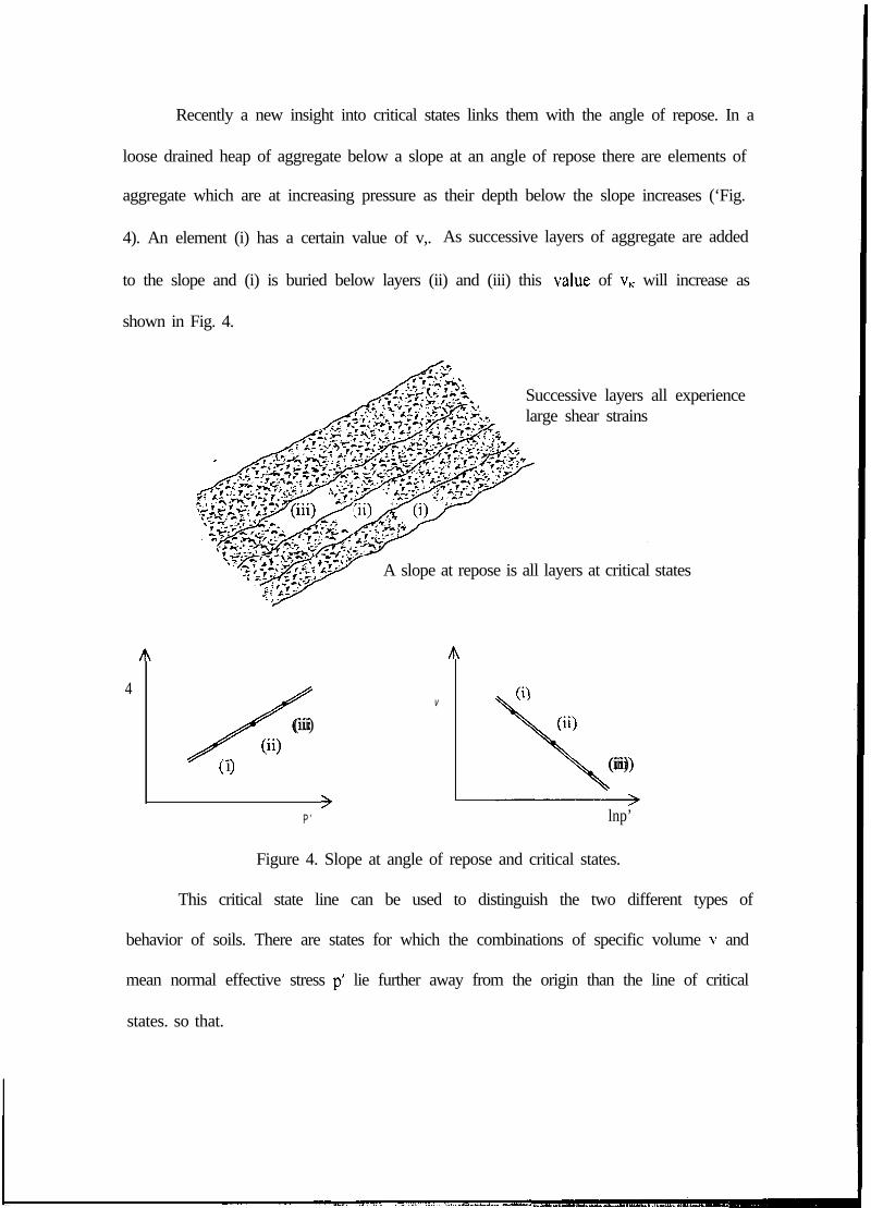
Recently a new insight into critical states links them with the angle of repose. In a
loose drained heap of aggregate below a slope at an angle of repose there are elements of
aggregate which are at increasing pressure as their depth below the slope increases (‘Fig.
4). An element (i) has a certain value of v,. As successive layers of aggregate are added
to the slope and (i) is buried below layers (ii) and (iii) this vlalue of v, will increase as
shown in Fig. 4.
Successive layers all experiencelarge shear strains
A slope at repose is all layers at critical states
A A
4
/
V (9
(iii) (ii)
Oi)( >i (iii)
>P ’ lnp’
Figure 4. Slope at angle of repose and critical states.
This critical state line can be used to distinguish the two different types of
behavior of soils. There are states for which the combinations of specific volume v and
mean normal effective stress p’ lie further away from the origin than the line of critical
states. so that.

v+hlnp’pr, or Vk + (3; - K) Ill p’ > r , or V?. ’ r (5)
and these states have been called “wetter than critical”; shearing there causes aggregates
to compress to more dense packing and emit water with ductile stable yielding of a test
specimen. There are also states of specific volume v and mean normal effective stress p’
such that
v + 3, In p’ 4= r , or vk + (h - K) In p’ < r , or VA < 1’ (6)
and these states have been called “drier than critical”; where shearing causes aggregates
to dilate and suck in water and ground slips at peak strength with unstable failures.
At the core of CSSM was the creation of the constitutive model called Cam-clay
based on the theory of plasticity, and the prediction of the successive ductile yielding
states of specimens on the wet side of critical. The original Cam-clay model (Fig. 5) was
synthesised from two basic equations.
The first says that if yielding obeys the stable associated plastic flow rule then the
product of the plastic flow increment (dv: ds) and any stress increment (dp’. dq) outward
directed from the yield locus is positive or zero - the zero applies to stress increments
directed along the tangent to the yield locus. This associated flow rule is entirely
appropriate to soil mechanics. The potter’s clay from which pottery vessels are moulded
by the potters hand is the archetypal plastic material. Ductile metals for which the
mathematical theory of plasticity was developed were thought of as malleable like potter!’
clay, and it would not be prudent to develop theoretical soil mechanics without insights
from plasticity theoIT.
The second equation says that when yielding occurs the work is purely frictional.
as proposed by Taylor (1948). In his research thesis Thurairajah (1961) reported the
~ 9

analysis of drained and undrained triaxial test data which confirmed Taylor’s proposal.
He did not begin the research with a prior intention of validating Taylor’s equation, and
his result came as a surprise. He took account of all work done by effective stresses on
all moving boundaries and of all elastic energy released or taken up by a swelling or
compressing aggregate under changes of p’. He found that the rate of dissipation during
shear distortion was simply in the product of p’ times the friction coefficient M. A lot of
data were analysed and a simple result emerged.
After eliminating the dilatancy rate dv/dr between these two equations a single
differential equation is left which then integrated predicts the form of the cam-clay yGeld
curve (CD in Fig. 5). The specimens on this line CD are all at one v, on one elastic
compression and swelling line. Curve CD allows stress to extend a certain distance
beyond the critical state line but there is a limit - when q = 0 the pressure cannot extend
further than D, if the material is to remain stable. If there were soil in states beyond D it
would be metastable. When salt is leached out of quick clay it gets into this dangerous
state and there is a risk of a quick clay avalanche.
C
I
Idp’ dv+dq de-0 - Associated flow rulep’ dv+q de-M p’ de - Energy dissipationq/Mp = IJIM = 1 -In(p’/p’cnt) - Yield curve
0 P ’ tn p’
Figure 5. Cam-clay yielding.
IO

It was a strong outcome of the synthesis of the original Cam-clay model that it
predicted an isotropic compression line v;. = I- -t (h - K) that bounded the region of wet
clay behaviour T > VI. > T + (h .. K), exactly as was first observed by Casagrande and
Albert (1930) and subsequently by Hvorslev (1937), Shibata (1963), and many others.
In Schofield and Wrath (1968) a simple material called Granta-gravel was
introduced, which is now seen as a version of Cam-clay with K = 0. The plot of v, versus
ln p’ allows CSSM to be taught without the need to introduce the idea of Granta-gravel.
Soil in a state drier than critical such as point F in Fig. 6(a) has been observed to
fail with well-defined rupture planes after reaching a peak strength fitting lines AB and
GE. This behavior is very familiar to geotechnical engineers. Based on a set of shear
box data on Vienna clay obtained by his student Hvorslev (1937), Terzaghi interpreted
clay/ peak strength in terms of a Mohr-Coulomb line with a slope termed “true friction”
and a “true cohesion” intercept (Fig. 6). Schofield and Wroth (1968) re-examined
Hvorslev’s data and found the Terzaghi and Hvorslev failure line applied only for a
restricted range of mean effective pressure and specific volume.
It has already been shown that the critical state line separates two different
regimes of behaviour. The region in which faulting is observed with dilation on gouge
material is the region to which Mohr-Coulomb peak strength applies. On the other side
of the critical state line there is a regime in which soil does not bifurcate but yields and
deforms as a continuum. The Cam-clay model describes the yielding behaviour in states
where layers can fold.
In states on the dry. side the particles remain interlocked with each other and peak
strength of soil involves a contribution from dilatancy of the interlocked stressed grains.
11

The dilating gouge material on the rupture planes will slowly soften to critical state plane
strengths fitting lines OB and OE (Fig. 6), although suction can persist for many years
provided the soil aggregate does not fissure or crumble.
Terzaghi’s Interpretation CSSM Interpretation
9
TrueCohesion
I
4
Figure 6. Limiting states of soil behavior.
The critical state line also form a bound to the region of faulting. There is a
broad region of states where faults.can occur and this region is bounded at low mean
effective pressure by soil cracks in tension. Among the alternative theories for tensile
fracture is “no tension“ or “limiting tensile strain”. For the triaxial specimen the no
tension criterion leads to o. = 0. which is the case of line OA. p’ = o,/>. qiy’ = 3, or to or
12

= 0 which is the case of line OG, p’ = 2&, q = -R, q/p’ = -2/3 (Fig. 6). Based on Weald
clay data, Schofield (1980) has suggested that the change to tensile fracture from
Coulomb rupture occurs in the vicinity of p’/pcrit = 0.1.
The characterisation of soil as cohesive or frictional is not regarded in CSSM as a
fixed property of a particular type of soil grain or mineral or pore fluid but rather depends
on the state of stress and the specific volume of soil. In this view it is wrong to
extrapolate the Mohr-Coulomb peak strength line to all ranges of pressure and specific
volume. Further discussion on Terzaghi’s Mohr-Coulomb error and its correction can be
found in Schofield (1998).
The simple division of soil behaviour based on critical state theory at limiting
states at one value of specific volume v shown in Fig. 6 divides the behaviour at limiting
states into three distinct classes of failure. The limiting lines OA and OG indicate states
limited by-fructures or.fissures; AB and GE indicate that Hvorslev’s Coulomb,fuuZ~s on
rupture planes will limit behaviour: BD and ED indicate Cam-clay yield and sediment
layer jhlds. The fractures, faults, and folds (FFF) diagram is useful to characterise all
classes of observed mechanisms of large displacements in soils.
Critical states. and the Harvard view of liauefaction. and Seed’s view.
Liquefaction is one aspect of the undrained behaviour of sands that has attracted
attention for many decades. In a notable contribution *to the Journal of the Boston Society
of Civil Engineers. Casagrande (1936) described liquefaction of an aggregate in states
more loose than the critical void ratio as if it were a phase transformation process such as
the melting of a solid and the change to a fluid. On the other hand. based on undrained
cyclic triaxial tests. Seed and Lee (1966) defined liquefaction as a phase transition but
13

now to the condition when pore pressure approaches the confining stress and effective
stress drops to zero. For Casagrande liquefaction had to be on the wet side of critical
states while for Seed it had to be on the dry side.
Schofield and Togrol (1966) and Schofield (198 1) highlighted the difficulties with
Casagrande’s original notion of a constant critical void ratio. Although Casagrande
moved from this position to the steady state of sands put forward by Poulos (1981), many
geotechnical engineers still use the word “critical” in the incorrect original sense.
Cam-clay is a model of uncemented soil aggregates on the wet side of the critical
state line that can continue to yield in a ductile stable manner as a continuum. Quick clay
is a lightly cemented or bonded soil aggregate, which can stand with vertical faces to
small cliffs. and should be regarded as a soft rock. In an undisturbed state it contains a
high water content and ‘does not flow. When a quick clay avalanche occurs this soft rock
disintegrates into a fissured debris. and as lumps of quick clay are remoulded their high
water content become evident. When the debris is fully remoulded it forms a body of soil
with even more water than the isotropic compression line, that is VI, >> IY + @-K). This is
not a change of grain positions. but a loss of bonds. The notion of liquefaction as an event
propagating with retrogressive slips in a meta-stable body of lightly cemented or bonded
collapsing silt and causing quick clay flowslides is consistent with critical state theory.
Centrifuge models performed at Cambridge on carefully sampled quick clay specimens
did produce quick clay flow slides. A \vide range of model tests at Cambridge also
considered other so-called liquifaction phenomena where there were quite different
mechanisms of failure. Schofield (1980) discussed such tests including those that
modelled Mississippi river bank liquefaction.
14


When a soil aggregate is unloaded following a stress path its effective stress
reduces towards zero leading to relaxation of stresses between grains. Such reduction in
stress may be induced by imposing tensile strain. or by increasing the pore water
pressure, or by cyclic loading. In each case, however, the soil particles remain
geometrically interlocked with each other even though the effective stress falls. In this
class of unloading paths if at any stage a large shear distortion were to be imposed on the
interlocked but lightly stressed particles they would respond by dilation- and the effective
stress path would head back towards the critical state line BH (Fig. 6).
When an unloading effective stress path reaches the fracture regions OA or OG
(Fig. 6) the continuum begins to disintegrate into a elastic body and unstressed grains
become free to slide apart. In that case the average specific volume of the elastic mass
and its permeability can increase greatly in a very short time. Whenever a soil is dug or
is crumbled, for ease of handling or for mixing with water, an unloading stress path
reduces a principal effective stress component to zero in a controlled manner. If,
however, there is a hydraulic gradient across the soil body at the time it cracks or
crumbles the event is less controlled and has the character of sudden hydraulic fracture or
fluidisation.
Accordingly. Schofield (198 1) in the St Louis conference defined liquefaction as
a class of instability (channelling. piping. boilin,.CT or fluidising) seen in soil far on the dry
side of critical states near zero effective stress and in the presence of a high hydraulic
gradient. This applies to the case of cyclic pore pressure in earthquake as well as to static
hydraulic fracture.
15

The opening within the soil body may be an extensive crack or a local pipe or
Channel. In the case Of a lOCal pipe, water slowly following tortuous paths may be able to
dislodge grains in a direction perpendicular to the axis in which the pipe is &veJoping. If
debris forms soft mud which blocks the channel the crack or pipe will heal itself. 1f
hydraulic pressure are transmitted along a pipe or crack to regions where the pressure
gradients cause cracking faster than cracks heal there is a sudden transmission of
pressures, and a body of crumbling soil can disintegrate into a sort of soil avalanche. Or
several pipes can break through a sand layer and vigorous sand boils can occur. This was
the class of liquefaction with which Seed was concerned. It is important to note.
however, that increase of excess pore pressure to the effective confining pressure is
necessary but not sufficient. The formation of openings and the presence of high
hydraulic gradient, which lead to disintegration of the continuum into elastic blocks of
soil, is another important requirement.
Dam failures
three common causes of disagreement with colleagues. Either he and they (i)
Casagrande began his Pan-American Conference lecture by saying that he found
looked at
: basis of
different
different aspects of the same problem. or (ii) generalised too much on the
different sorts of experimental data. or (iii) used the same terminology for
phenomena. Many disagreements about CSSM arise from these causes. This paper will
ask if there is agreement about the word “liquefaction”, and will consider only those
aspects of three dam failures that relate to that word. The failure of a dam usually has .
several complex aspects, some of which are never fully understood. The concept of a
prilllary cause or a triggering mechanism is in itself debatable when subsidiary causes of
16
failure are needed. It is unusual to have reliable witnesses who report the events and
during the event key elements involved in the process of failure may disappear.
The three dam failures that are discussed were interpreted in detail long ago. It is
not feasible or necessary to present here all details of the site conditions. the design
features. and the sequence of events preceding each failure. as excellent summaries of all
these aspects are readily available. For example, Middlebrooks (1942) and subsequent
discussions present a detailed account of the Fort Peck slide. The comprehensive report
of the international workshop on dam failures edited by Leonards (1986) gives detailed
accounts of the Baldwin Hills reservoir and Teton Dam failures. Therefore our review
only asks if those conditions brought them into the class of instability discussed above.
Were the Fort Peck Dam, Baldwin Hills Reservoir and Teton Dam failures due to soil
behaviour on the wet side or the dry side of critical states?
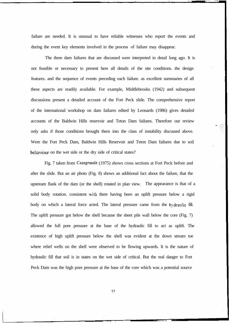
Fig. 7 taken from Casagrande (1975) shows cross sections at Fort Peck before and
after the slide. But an air photo (Fig. 8) shows an additional fact about the failure, that the
upstream flank of the dam (or the shell) rotated in plan view. The appearance is that of a
solid body rotation. consistent with there having been an uplift pressure below a rigid
body on which a lateral force acted. The lateral pressure came from the h!.draulic fill.
The uplift pressure got below the shell because the sheet pile wall below the core (Fig. 7)
allowed the full pore pressure at the base of the hydraulic fill to act as uplift. The
existence of high uplift pressure below the shell was evident at the down stream toe
where relief wells on the shell were observed to be flowing upwards. It is the nature of
hydraulic fill that soil is in states on the wet side of critical. But the real danger to Fort
Peck Dam was the high pore pressure at the base of the core which was a potential source
17

- El. 2300- Final Crest El. 2 I X0
- El. 2300----A
FORT PECK DAM-
,l<.R. Traclr~.~ ,,,,
- El. 2200(‘ross Section Through Slide at Stm 22+00
Vertical Scale = 5 tinm Hark Scale-
-
-
-- - Hcscrvoir Et. 2 I I7
- [‘I, 2 100 -z--
- El.
,220o
2 1 0 0
\- ) Chiefly Alluvial Sands
-
/ ~ Shale surface-
- E l . 2000
El. 2300
El. 2200
*’I 1 Core ‘**.,
Sheet Pile Wall-
El. 2300
I~igurc 7. Schematic of the cross-section of Fort Peek Dam before and after failure (Casagrande, 1976).

Figure 8. Partial failure of Fort Peck Dam as seen from the air.
of uplift. and the sheet pile wall delivered the pressure to all permeable layers below the
dam. No doubt the designers thought of the sheet piles as preventing loss of water
through permeable layers below the reservoir. but failed to realize that the very high pore
pressure at the base of the core had this destructive potential. The upstream shell of the
dam would have failed first because it was partially bouyant in the early reservoir filling.
The hydraulic fill had practicaliy no effective stress and so it would flow as slurry. There
was no need to postulate a “flop. structure”. such as Casagrande supposed that allowed
large cobbles to be carried along end pipes. This is not to say that his flow structure is
not possible; simply that it is not essential to the explanation of the failure of the Fort
Peck dam.
Fort Peck was the Lvork of the U.S. Army in a great river valley. Baldwin Hills
and Teton were the works of the Los Angeles Division of Water and Po\ver and the U.S.
Bureau of Reclamation in the much more dry conditions out west. R.R. Proctor worked
19
for LOS Angeles Division of Water and Power and his ability to achieve very ]lig]l
compaction was evident in the steepness of the breach that was left after the Baldwin
Hills Reservoir failed. The U.S.B.R had built a series of rather similar dams before
Teton. and the control of compaction that was achieved became tighter in each successive
dam. The great strength that was achieved in the final dam in Teton gorge is evident in
the photograph of almost vertical strong faces on either side of the breach while the entire
contents of the dam ran out. Both these embankment dams were built of soil in states
which would be described in CSSM as very much on the dry side of critical. Both were
made of low plasticity soil in a very brittle state.
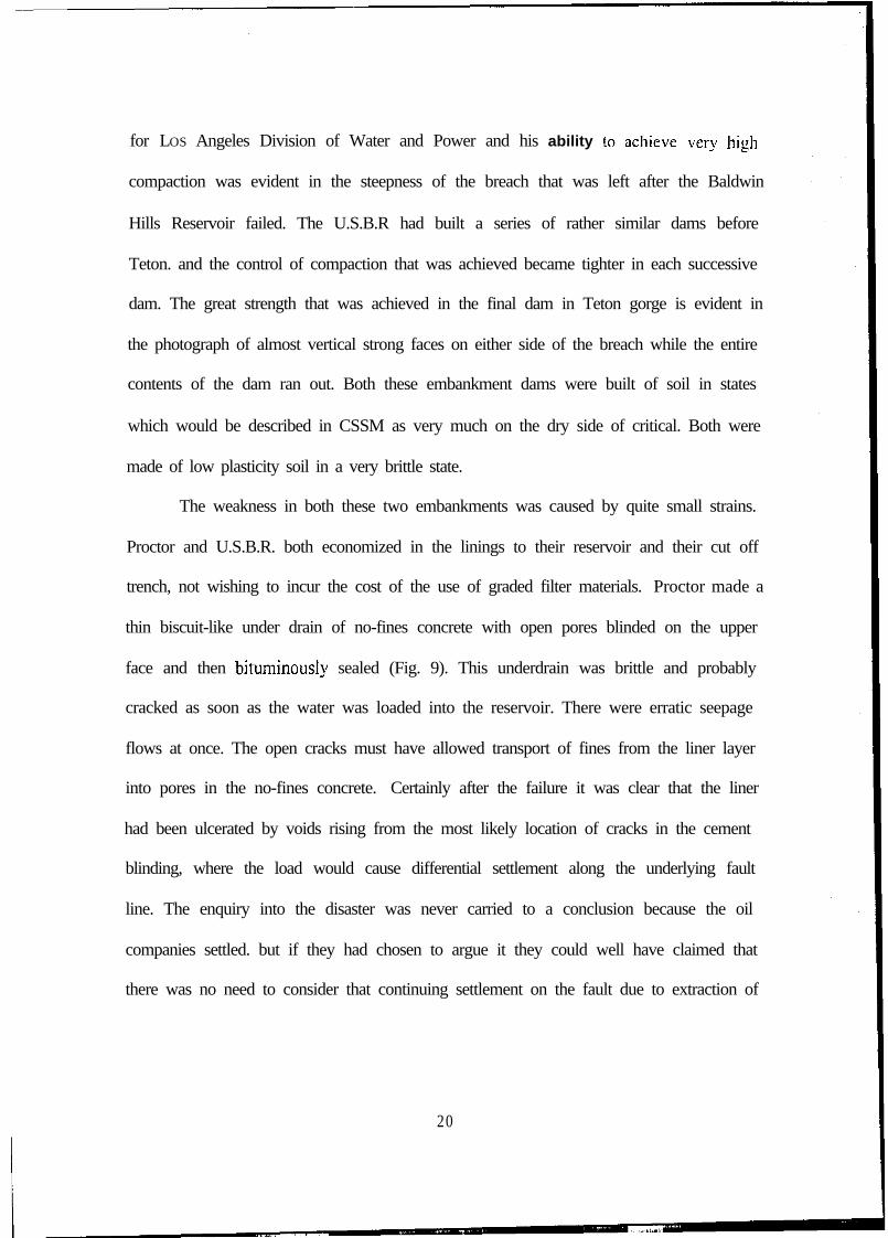
The weakness in both these two embankments was caused by quite small strains.
Proctor and U.S.B.R. both economized in the linings to their reservoir and their cut off
trench, not wishing to incur the cost of the use of graded filter materials. Proctor made a
thin biscuit-like under drain of no-fines concrete with open pores blinded on the upper
face and then bituminously sealed (Fig. 9). This underdrain was brittle and probably
cracked as soon as the water was loaded into the reservoir. There were erratic seepage
flows at once. The open cracks must have allowed transport of fines from the liner layer
into pores in the no-fines concrete. Certainly after the failure it was clear that the liner
had been ulcerated by voids rising from the most likely location of cracks in the cement
blinding, where the load would cause differential settlement along the underlying fault
line. The enquiry into the disaster was never carried to a conclusion because the oil
companies settled. but if they had chosen to argue it they could well have claimed that
there was no need to consider that continuing settlement on the fault due to extraction of
20

oil caused the break. Once the no-fines concrete cracked it was simply a matter of time
before the ulceration broke through.
‘n I ,- ASPHALTIC PAVING ASPHALlIC PAVING
ASPHALTIC MEMBRANE
PEA-GRAVEL DRAIN
L ~A”ASPHALTlC MEMBRANE
TYPICAL SECTION TliROUGH L I N I N G
Figure 9. Main features of Baldwin Hills reservoir lining.
Following the Teton Dam failure on June 5 1976 an Independent Panel reviewed
the cause of failure and reported to the U. S. Department of the Interior and the State of
Idaho in December 1976. The Independent Panel’s report included an analysis of
hydraulic fracturing and its possible role in the Teton Dam failure (Seed et al. 1976). The
present review begins with a comment that the analysis did not consider the tensile strain
conditions necessary for fracture.
Seed et al. (1976) reported the FE analysis of the cause of cracking in the Teton
Dam key trench. Their total stress computations implied certain lateral stress on the
walls of the trench. and \f%en they took away the pore pressure that they found that for
steady state seepage from the filled dam they obtained a tensile stress component. But
21
this could not be a correct analysis. Tensile cracking results from lateral tensile strain,
and the walls of the rock trench would have had to move apart to allow that to happen.
An analogy would be if an oedometer had soil compacted in it and there were lateral
stresses on the walls of the cylinder. If a pore pressure exceeding the lateral stress were
to be injected into the oedometer it would not make a vertical crack in the soil inside
unless it was able to cause internal pressure failure of the metal cylinder. The sidewalls
would carry part of the stress. This comment was made by the second author of this
paper to the late Professor Seed in April 1977.
Following discussion with U.S.B.R. in Denver various tests were undertaken both
on the newly installed small centrifuge at UC Davis. and on the large beam centrifuge in
Cambridge. In both test series tensile cracks were induced in tubs full of compacted
Teton core material, and studies were made of erosion and void migration. The
conclusion of those tests (Schofield’s confidential report to USBR in 1980) was that the
soil was highly susceptible to cracking. Even the strains caused by filling the dam
probably were sufficient to cause extensive cracking. When such cracks were subjected
to seepage with slowly increasing reservoir levels they tended to collapse, leaving a mud
filled sealed crack and a rising void. The key to safety in such circumstances is to ensure
that whenever cracks and rising voids occur there is material that can plug the voids. III
this view it is important to have a downstream graded filter layer that can collapse and fill
any’ void whenever it arises. It is also very significant that the actual rapid filling of
Teton allowed JIO time for self healing of cracks.
The 1980 Rankine lecture (Schofield 1980) mapped soil behavior described here
011 p’/p’crii against q/p’crit (Fi,.‘a 6) on axes of liquidity index against logarithm of pressure

(Fig. 10). At any si\‘en liquidity, as effective mean-normal pressure increases, the mode
of failure changes from fractures or fissures, to Coulomb faults or ruptures.‘and to yield
or folds with plastic volume change. The stress ratio q/p’ that can be carried by the soil
increases as pressure and liquidity fall - the insert shows a section across the map at
constant p’. This increased strength and stiffness tempts engineers to compact soil more
and more. until they meet a new problem. When stiff soil becomes fissured its
permeability increases very greatly. A fracture will involve open voids and channels,
whereas Coulomb rupture preserves soil still in a relatively impermeable mass. In this
sense it is safer to have softer and more ductile soil construction which remains water-
tight even when ruptured.
MAP
Figure 10. Liquidity and limits of soil behavior. -
Considering a body of soil initially at LI = 0.5 and subject to elastic compression
the map suggests at shallow depths where p < 5 kPa there may be cracks. but for depths
where j < p c j0 kPa the soil will remain Mlater-tight while deforming. In contrast a
2 3 I

_ -...-----.-..
body of soil initially at LI _< 0 will be susceptible to fracture at depths for which p < jo
kPa; taking account of elastic compression it could require an overburden depth of say jo
m of drained soil or 100 m of buoyant soil to ensure that deformation caused water tight
rupture planes rather than open pemleable cracks. In this view the steep vertical face of
the breach in Teton Dam can be seen as an open fracture in a very strong soil, standing to
a height of 50 m to 100 m.
The emphasis in undergraduate teaching in Cambridge that arose as a result of
many years of centrifuge model testing, was that overcompaction should always be
regarded as risky. Near critical states where equivalent liquidity (Schofield 1980) is 0.5 <
LIs, compacted soil retains something of the toughness that is associated with ductile
mild steel. At Teton the core was probably compacted to LIs ‘< 0, which is as fragile, as
glass. The dam was bound to crack. It was disastrous to try to fill the dam more rapidly
than ever been done before. .
Summarv and Conclusions
All classes of observed mechanisms of large displacements in soils could be
characterised into three distinct classes; folds, faults. and fractures. An aggregate of
grains wetter than critical states yield in a ductile stable manner. A layer of such
sediment forms folds during deformation but it does not fail. Cam-clay describes the
ductile stable yielding. If a soil aggregate is drier than the critical state. it can fail with
fault planes on which gouge material dilates and softens, or it can fracture and crack into
a elastic debris. or develop pipes and channels. Generalising too much on the basis of
different sorts of experimental data without an understanding of the distinct classes soil
behaviour has led to many disagreements on critical state soil mechanics.
24
Critical state soil mechanics associates rapid geotechnical disasters with soil on
the dry side of critical states being brought near to zero effective stress while in the
presence of a high hydraulic gradient. The three dam failures discussed here were all due
to soil behavior on the dry side of critical. The Baldwin Hills and Teton dam were
failures with cracks and pipes induced by overcompaction. We see no evidence of
Casagrande’s “flow structure” of sand in the liquefaction of the Fort Peck darn failure.
Rapid transmission of pore pressure gradients through soil near zero effective stress
seems to us a better explanation of liquefaction failure on the “dry side” of critical states
than Casagrande’s transformation of the grain structure of sand by a “chain reaction”
propagating through an aggregate of soil grains.
Acknowledgements:
This study was performed while the first author was on leave at Cambridge UniversityEngineering Department. An International Fellowship Award from the National ScienceFoundation (INT-9802887) and fellowship from Churchill College, Cambridge.sponsored the visit.
REFERENCES
Casagrande, A. (1936a). “Characteristics of cohesionless soils affecting the stability ofslopes and earth fills.” Journul of the Boston Society qf Civil Engineers. January:reprinted in Contributions to Soil Mechunics 1925-1940, BSCE. pp. 25 J-276.
Casagrande, A. (1975). “Liquefaction and cyclic deformation of sands. a critical review.”Proceedings of the Fffih Punornericm Conference on Soil Mechanics undFoundation Engineering, Buenos Aires: reprinted as Harvard Soil MechanicsSeries. No. 88. 27 pp. (1976).
Casagrande, A., and S. G. Albert (1930). “Research on the shearing resistance of soils.”Massachusetts Institute of Technology,. Unpublished.
Castro. G. (1969). “Liquefaction of Sands.” PhD Thesis, Harvard University; reprintedas Hazard Soil Mechanics Series. No. 8 l- 112 pp.
Hvorslev, M.J. (1937). iiher die Festigkeitsei~ellsch~~en Gestiirter Bindiger Bijdm.Kopenhavn.
25

Leonards. G.A. (Ed.) (1986). “Special issue on Dam failures.” Engineering Gco~o~:,24( 1-4).
Middlebrooks, T.A. (1942). “Fort Peck slide.”764.
Tkmsactiom, ASCE, Vol. (107) pp. 723-
Poulos, S.J. (198 I). “The steady state of deformation.” ASCE, Jour. Geot. Engrg.,.107(5). pp. 553-562.
Roscoe, K.H. and Schofield: A.N. (1963). “Mechanical behaviour of an idealised ‘wetclay’.” Proc. 2 ’” Europeun Co~f: o n S o i l kkchunics und FoundutionEngineering, Wieshuden, Vol. 1 _ pp. 47-54.
Roscoe, K.H., Schofield, A.N., and Wroth. C.P. (1958). “On the yielding of soils.”Gc!otechnique,. 8(l), pp. 22-53.
Schofield, A.N. (1966). “Original teaching on cam-clay.” Lecture notes, CambridgeUniversity Engineering Department,
Schofield, A.N. (1980). Cambridge geotechnical centrifuge operations, 20”’ RankineLecture. GQotechnique, X(3), pp. 227-268.
Schofield, A.N. (198 1). “Dynamic and earthquake geotechnical centrifuge modeling.”State of Art lecture, Symposium on Recent Advances in Geotechnical EarthquakeEngineering and Soil Dynamics. St. Louis, MO.
Schofield, A.N. (1998). “Geotechnical centrifuge development can correct soilmechanics errors.” Keynote Lecture, Centrifuge 98. Tokyo.
Schofield, A.N. and Togrol, E. (1966). “Critical states of soil.” Bulletin of the TechniculUniversity qf Istanbul, No. 19. pp. 39-56.
Schofield. A.N. and Worth. P. (1968). Critical State Soil h4echanics. McGraw-Hill.
Seed. H.B. (1979). “Soil liquefaction and cyclic mobility evaluation for level groundduring earthquakes.” ASCE, Jot/r. Geotech. Engr. ~ 105(2), pp. 20 l-255:
Seed, H.B. and Lee, K.L. (1966). “Liquefaction of saturated sands during cyclicloading.” ASCE Jaw. Soil A4ech. Found.. 92(6): pp. 105- 134.
Seed, H.B., Leps, T.M., Duncan. J.M. and Bieber, R.E. (1976). “Hydraulic fracturingand its possible role in the teton dam failure,” Appendix D of Report to CIS. Dept.of’the Interior md State of’ldaho on Failure qf Teton Dam by Independent Punchto Review Came ef!f‘Teton Dam Fuilzne. December. pp. Dl -D39.
Shibata. T. (1963). “On the volume changes of normally-consolidated clays” (inJapanese). Disaster Prevention Rcsemch Institute .3nnals. h’yoto U&v-sit-y. Vol.6. 128-134.
26

27