lionel train set owner’s manual · pdf filetrack assembly and layout ... there should be...
TRANSCRIPT
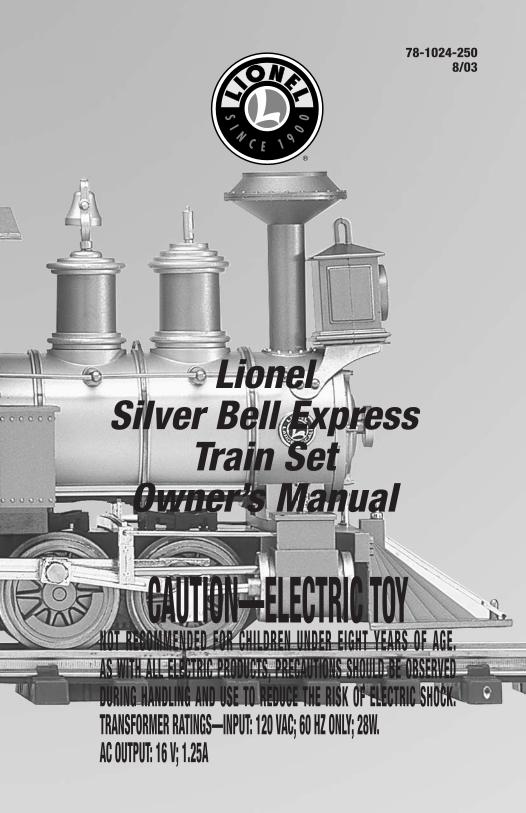
78-1024-2508/03
CAUTION—ELECTRIC TOYNOT RECOMMENDED FOR CHILDREN UNDER EIGHT YEARS OF AGE.AS WITH ALL ELECTRIC PRODUCTS, PRECAUTIONS SHOULD BE OBSERVEDDURING HANDLING AND USE TO REDUCE THE RISK OF ELECTRIC SHOCK.TRANSFORMER RATINGS—INPUT: 120 VAC; 60 HZ ONLY; 28W.AC OUTPUT: 16 V; 1.25A
LionelSilver Bell Express
Train SetOwner’s Manual
2
Congratulations!
Congratulations on your purchase of the Lionel Silver Bell Express Train Set! No matterwhere you place this set—around the tree or on a table—everyone will enjoy watching
your train and its festive load as it winds through your holiday celebrations.Read this instruction manual thoroughly for important tips on operating and maintaining
your Silver Bell Express Christmas Train Set. When properly cared for, it will last a lifetime.Experience the superiority of today’s Lionel.
• Powerful maintenance-free motor
• Operating headlight
• Holiday gondola with bells
• Musical caboose
• Lionel power and control system
• Twelve sections of Large Scale track
• Santa figure
Silver Bell Express Train Set Inventory
The transformer included with this set should be periodicallyexamined for conditions that may result in the risk of fire,electric shock, or injury to persons (such as damage to theoutput cord, blades, housing, or other parts). In the event thatsuch conditions exist, the transformer should not be used untilproperly repaired.
Parents!
The following Lionel marks may be used throughout this instruction manual and are protected under law.All rights reserved.
Lionel®, TrainMaster®, Odyssey®, RailSounds®, CrewTalk™, TowerCom™, DynaChuff™,StationSounds™, Pullmor®, ElectroCoupler™, Magne-Traction®, CAB-1 Remote Controller®,PowerMaster®, Lionel ZW®, ZW®, PowerHouse®, TMCC®, Lionelville™, Lockon®
The name FasTrack® is used with permission from Pitsco, Inc.
3
Table of contents
Track assembly and layoutGetting started 4Joining the track sections 5Powering your set 6
Controller operationsOperating the controller 7Controller and short circuits 8
Train operationsInstalling Santa figure 9Positioning the bells in the gondola 9Coupling the cars 10Installing and operating the hook and loop couplers 11Operating your musical caboose 12
Maintaining your setReplacing the lamp 13Maintenance and lubrication 14Notes 15Limited Warranty/Lionel Service 16
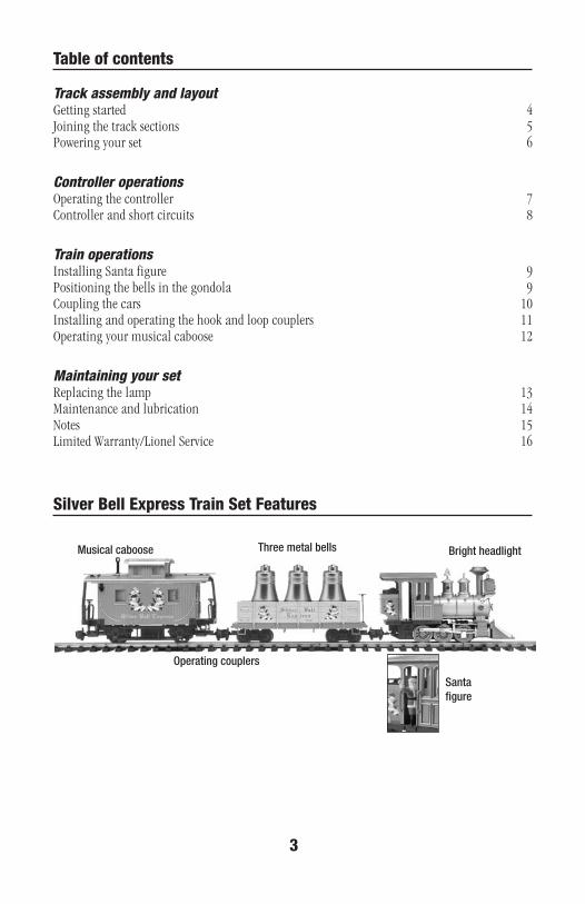
Silver Bell Express Train Set Features
Bright headlight
Operating couplers
Santafigure
Three metal bellsMusical caboose

4
Track assembly and layoutGetting started
Before you do anything else, we recommend that you check the contents of your set box toensure all of the parts of your set have been included and that the quantities (when
applicable) are correct.Table 1 tells you what’s included and the correct quantities. If you find any discrepancies,
contact the dealer you purchased your set from for more information or call 1-800-4-LIONEL.
• 0-6-0 Holiday locomotive 1
• Holiday gondola with three bells 1
• Holiday musical caboose 1
• Replacement hook and loop couplers 5
• Controller 1
• UL approved power pack 1
• Lockon 1
• Power wire with spade connectors 1
• Curved track 12
• Santa figure 1
• Bag of cotton 1
Table 1. Set contents

5
Track assembly and layout
Join the track sections together by inserting the pins of each track section into the railopenings of another section. Refer to Figure 1. Pins must be fully inserted and track joints
tightly fitted for good electrical contact. The plastic track sections snap together to assurecorrect assembly. With the track included in this set, you can create a circle. Expand your layoutwith additional sections of straight and curved track, available at your authorized Lionel dealer.
All electrical connections should be clean and tight. The track should fit together firmly. Ifthe rail openings have become enlarged and fit together loosely, pinch the rail around a trackpin with a pair of pliers. If any pins fall out of the track, be sure to replace them.
The rails should be kept clean, dry, and free from oil and grease. Clean off tarnish and dirtspots with any commercial brass cleaner or non-abrasive metal polishing pad to keep your trackin top condition. Wipe the track with a clean soft cloth dampened with track cleaner from theLionel Lubrication and Maintenance Set (6-62927).
Joining the track sections
Figure 1. Track assembly

Track assembly and layoutPowering your set
The Lockon connects power from yourcontroller to the track. Attaching the
Lockon to the track is simple. First, placethe Lockon under any curved section oftrack between the ties. Fit the flange of theoutside rail into the squared brass contacton the Lockon. Press the Lockon upward sothat the spring contact snaps onto theinside rail. The Lockon should face outwardwhen setting up your track and must befirmly connected. Refer to Figure 2.
Squared brasscontact
Spring contact
Inner rail
Lockon
Brassflange ofouter rail
The stripped ends of the wire must be insertedinto the spring clips on the Lockon. This isdone by pushing down the upper half of theclip until the metal loop in the lower partprojects through the top. Insert the bare end ofthe wire into the loop and release the clip. SeeFigure 3. Spring tension will hold the wiretight.
Next, connect the spade-shaped connectorsat the ends of the wire to the thumbscrewterminals on the back of the controller.Loosen the thumbscrew and position thepost between the “blades” of the spadeconnector. Be sure that the blades are incontact with the thumbscrew post. Tightenthe thumbscrew to secure the connection.The set-up should now look like the oneshown in Figure 4. Plug the wall pack intoany standard outlet and plug the end intothe jack in the back of the controller. SeeFigure 5 on page 7.
Figure 4. Completed wiring
Figure 3. Wire connections
Figure 2. Attaching the Lockon
6

7
Operating the controller
OFF
FULL
SPEED
R
Plug this endinto the backof thecontroller.
Plug the power packinto a standard walloutlet
As you turn the throttle control knob to the right, power to the track is increased. Refer toFigure 5. When the indicator reaches the green band, there should be sufficient power to
operate the locomotive. The further into the green area the knob is turned, the faster your trainwill go. Remember that the greater the load on the engine (adding more cars for the engine topull, for example), the further into the green the knob must be turned before it will operate thelocomotive.
The yellow band indicates the average power range that the train will be operating in. The redband represents maximum power output.
Throw this switch to changedirection.
Turn the throttle controlknob to the right for morepower.
The LED indicator shows whenyour controller is on.
FULLSPEED
OFF
Green band
Yellowband
Redband
Parents should periodically inspect the power pack for potential hazards such as a broken or damagedcase and have it repaired or replaced. See the Lionel Service Station listing for information and theaddress of the nearest Authorized Service Station. Or visit us on the Internet at www.lionel.com
Controller operations
Figure 5. Controller features
8
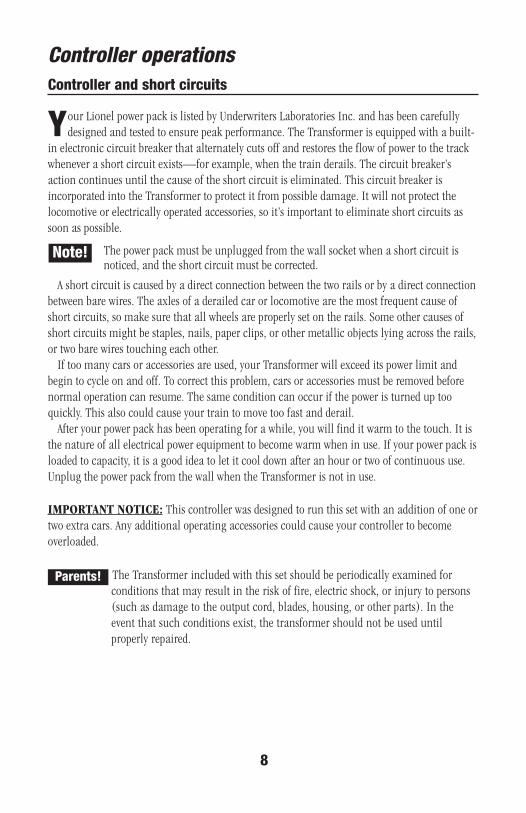
Controller and short circuits
IMPORTANT NOTICE: This controller was designed to run this set with an addition of one ortwo extra cars. Any additional operating accessories could cause your controller to becomeoverloaded.
Controller operations
Your Lionel power pack is listed by Underwriters Laboratories Inc. and has been carefullydesigned and tested to ensure peak performance. The Transformer is equipped with a built-
in electronic circuit breaker that alternately cuts off and restores the flow of power to the trackwhenever a short circuit exists—for example, when the train derails. The circuit breaker’saction continues until the cause of the short circuit is eliminated. This circuit breaker isincorporated into the Transformer to protect it from possible damage. It will not protect thelocomotive or electrically operated accessories, so it’s important to eliminate short circuits assoon as possible.
The power pack must be unplugged from the wall socket when a short circuit isnoticed, and the short circuit must be corrected.
A short circuit is caused by a direct connection between the two rails or by a direct connectionbetween bare wires. The axles of a derailed car or locomotive are the most frequent cause ofshort circuits, so make sure that all wheels are properly set on the rails. Some other causes ofshort circuits might be staples, nails, paper clips, or other metallic objects lying across the rails,or two bare wires touching each other.
If too many cars or accessories are used, your Transformer will exceed its power limit andbegin to cycle on and off. To correct this problem, cars or accessories must be removed beforenormal operation can resume. The same condition can occur if the power is turned up tooquickly. This also could cause your train to move too fast and derail.
After your power pack has been operating for a while, you will find it warm to the touch. It isthe nature of all electrical power equipment to become warm when in use. If your power pack isloaded to capacity, it is a good idea to let it cool down after an hour or two of continuous use.Unplug the power pack from the wall when the Transformer is not in use.
Note!
The Transformer included with this set should be periodically examined forconditions that may result in the risk of fire, electric shock, or injury to persons(such as damage to the output cord, blades, housing, or other parts). In theevent that such conditions exist, the transformer should not be used untilproperly repaired.
Parents!
9
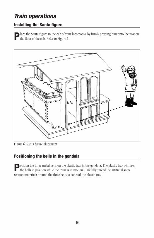
Train operationsInstalling the Santa figure
Place the Santa figure in the cab of your locomotive by firmly pressing him onto the post onthe floor of the cab. Refer to Figure 6.
Position the three metal bells on the plastic tray in the gondola. The plastic tray will keepthe bells in position while the train is in motion. Carefully spread the artificial snow
(cotton material) around the three bells to conceal the plastic tray.
Positioning the bells in the gondola
Figure 6. Santa figure placement
10
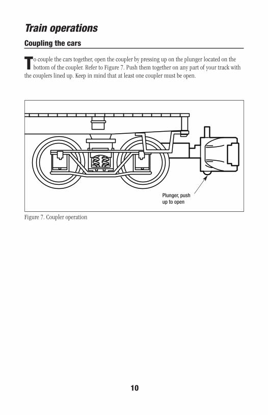
Train operationsCoupling the cars
Plunger, pushup to open
To couple the cars together, open the coupler by pressing up on the plunger located on thebottom of the coupler. Refer to Figure 7. Push them together on any part of your track with
the couplers lined up. Keep in mind that at least one coupler must be open.
Figure 7. Coupler operation
11
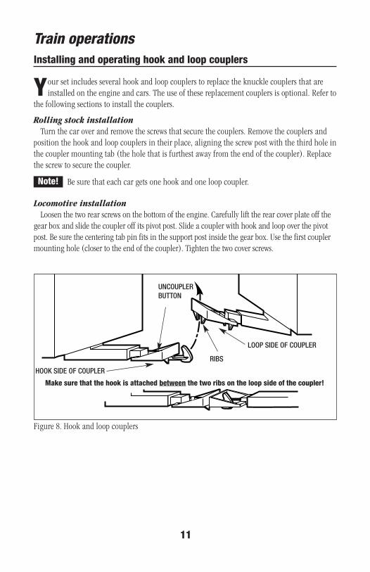
Installing and operating hook and loop couplers
Train operations
Figure 8. Hook and loop couplers
UNCOUPLERBUTTON
RIBS
HOOK SIDE OF COUPLER
LOOP SIDE OF COUPLER
Make sure that the hook is attached between the two ribs on the loop side of the coupler!
Your set includes several hook and loop couplers to replace the knuckle couplers that areinstalled on the engine and cars. The use of these replacement couplers is optional. Refer to
the following sections to install the couplers.
Rolling stock installationTurn the car over and remove the screws that secure the couplers. Remove the couplers and
position the hook and loop couplers in their place, aligning the screw post with the third hole inthe coupler mounting tab (the hole that is furthest away from the end of the coupler). Replacethe screw to secure the coupler.
Be sure that each car gets one hook and one loop coupler.
Locomotive installationLoosen the two rear screws on the bottom of the engine. Carefully lift the rear cover plate off the
gear box and slide the coupler off its pivot post. Slide a coupler with hook and loop over the pivotpost. Be sure the centering tab pin fits in the support post inside the gear box. Use the first couplermounting hole (closer to the end of the coupler). Tighten the two cover screws.
Note!
12
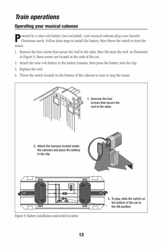
Train operations
Powered by a nine-volt battery (not included), your musical caboose plays your favoriteChristmas carols. Follow these steps to install the battery, then throw the switch to start the
music.
1. Remove the four screws that secure the roof to the sides, then lift away the roof. As illustratedin Figure 9, these screws are located at the ends of the car.
2. Attach the nine-volt battery to the battery harness, then press the battery into the clip.
3. Replace the roof.
4. Throw the switch located on the bottom of the caboose to start or stop the music.
Operating your musical caboose
2. Attach the harness located insidethe caboose and place the batteryin the clip
3. To play, slide the switch onthe bottom of the car tothe ON position
Figure 9. Battery installation and switch location
1. Unscrew the fourscrews that secure theroof to the sides
OFF ON

13
Maintaining your set
The locomotive’s lantern headlight operates off track power. If the lamp burns out, unscrewthe lantern box from the lantern bracket and lift it away. See Figure 10 below. Unscrew the
lamp and install a replacement (Lionel part no. 818-5101-139), available from yourauthorized Lionel Service Center or from Lionel Service.
Headlightlamp bracket
Part no. 818-5101-139
Lamp socket
Screw
Replacing the lamp
Headlight lantern box
Figure 10. Lamp replacement

14
Maintaining your set
Do not attempt to disassemble and/or lubricate your locomotive’s motor. This locomotivehas been factory-tested, and the necessary internal parts have been
sufficiently lubricated for life at the factory. If your locomotive requires service, pleasebring it to an authorized Lionel Service Station or Lionel Service for assistance. See page 16 foradditional information.
If you should experience any squeaking around the side rod areas of the locomotive, you mayuse a drop or two of Lionel Oil, available in the Lubrication and Maintenance Set (6-62090).You may also add a drop of oil where the locomotive axles meet the frame.
It is very important to keep the track and wheels free from dirt and grease. Wipe themwith a soft cloth whenever they get dirty. This will help the engine run moreefficiently.
Maintenance and lubrication
Note!
Figure 11. Locomotive lubrication
Lubricate withLionel oilsparingly Lubricate with
Lionel oilsparingly

15
Notes
Limited Warranty/Lionel Service
T his Lionel product, including all mechanical and electrical components, moving parts, motors andstructural components, except for light bulbs, is warranted to the original consumer-purchaser, for one
year against original defects in materials or workmanship when purchased through an authorized Lionelmerchant.
This warranty does NOT cover normal wear and tear, light bulbs, defects appearing in the course ofcommercial use, or damage resulting from abuse or misuse of the product by the purchaser. Transfer of thisproduct by the original consumer-purchaser to another person voids this warranty. Modification of this productvoids this warranty.
Any warranted product which is defective in original materials or workmanship and is delivered by theoriginal consumer-purchaser to Lionel L.L.C. or an authorized Lionel L.L.C. Service Center, together with proof oforiginal purchase will, at the option of Lionel L.L.C., be repaired or replaced, without charge for parts or labor. Inthe event the defective product cannot be repaired, and a replacement is not available, a refund of the originalpurchase price will be granted. Any products on which warranty service is sought must be sent freight or postageprepaid, as transportation and shipping charges are not covered by the warranty.
In no event shall Lionel L.L.C. be liable for incidental or consequential damages.Some states do not allow the exclusion or limitation of incidental or consequential damages, so the above
exclusion may not apply to you.This limited warranty gives you specific legal rights, and you may have other rights which vary from state
to state.
Instructions for Obtaining ServiceIf service for this Lionel L.L.C. product is required, bring the item, along with your dated sales receipt and
completed warranty information to the nearest Authorized Lionel Service Center. Your nearest Lionel ServiceCenter can be found by calling 1-800-4-Lionel, or by accessing our Website at www.lionel.com.
If you prefer to send your product back to Lionel L.L.C. for repair in Michigan, you must first call 586-949-4100 or FAX 586-949-5429, or write to Customer Service, P.O. Box 748, New Baltimore, MI 48047-0748,stating what the item is, when it was purchased and what seems to be the problem. You will be sent a returnauthorization letter and label to ensure your merchandise will be properly handled upon receipt.
Once you have received your return authorization and label, make sure that the item is packed to preventdamage during shipping and handling. We suggest that you use the product’s original packaging. Thisshipment must be prepaid and we recommend that it be insured.
Please make sure you have followed all of the above instructions carefully before returning anymerchandise for service. You may choose to have your product repaired by one of our Authorized Lionel ServiceCenters after its warranty has expired. A reasonable service fee will be charged.
Warranty InformationPlease complete the information below and keep it, along with your dated sales receipt. You must present
this and your dated sales receipt when requesting warranty service.
Name ________________________________________________________________________
Address ______________________________________________________________________
Place of Purchase ________________________________________________________________
Date of Purchase ________________________________________________________________
Product Number ________________________________________________________________
Product Description ______________________________________________________________
©2003 LIONEL L.L.C., CHESTERFIELD, MI 48051-2493UNITED STATES OF AMERICAPRINTED IN CHINA