lion - :: saturn · 2 dear customer, you have become the owner of a protherm lion wall-mounted...
TRANSCRIPT

Operation andInstallation Guide
24 KKV 28 KKV28 KKO
Wall-mounted condensing boiler
Output range 5 - 27,9 kW / 5,7 - 31,7 kW
Hot water heating (24 / 28 KKV)
Lion
xxxxxxxxxx_00- v.1 7/2007
ENve r s i o n
1
Table of contents
Introduction ........................................... 2
OPERATING INSTRUCTIONS
Controls and signals ............................. 4
Control panel ......................................... 4
Selecting Read mode ............................ 5
Selecting Setup mode .......................... 5
Error codes and troubleshooting .......... 6
Boiler control scheme ........................... 7
Starting the boiler and turning it off ...... 8
Boiler control ........................................ 8
Protective functions .............................. 9
Service and maintenance .................. 10
Warranty and warranty conditions ...... 11
Technical parameters ......................... 12
Boiler connection dimensions ............. 15
Usable gauge pressure to the system . 15
Function schematic diagram .............. 16
INSTALLATION INSTRUCTIONS
Introduction ........................................ 18
Completeness of delivery ................... 20
Preparing for installation .................... 22
Installing the boiler ............................. 24
Air supply and fl ue gases removal ...... 28
Components of concentricØ 60/100 fl ue gas removal .................. 32
Components of concentricØ 80/125 fl ue gas removal .................. 33
Components of separateØ 80 / 80 ............................................. 36
Electrical wiring ................................... 40
Interconnecting boiler withhot water tank ...................................... 42
Conversion to other fuel ...................... 42
Boiler electric wiring diagram ............. 43
Protherm Lion 24 KKV, 28 KKV, 28 KKO
The boiler Serial No. is shown on the plate which is attached to the back of the electrical cabinet of control panel. The control panel is situated on the front face of the boiler.
In section “Operating Instructions” you will fi nd description of the boiler’s main functions and guidelines how to handle the boiler safely. Section “Installation Instructions” is for
competent workers only.

2
Dear customer,
you have become the owner of a Protherm Lion wall-mounted condensing boiler, designed to run on natural gas.
Please note: The boiler can be also run on propane, too, provided the requirements detailed in this Operation and Installation Guide are met.
Lion 24 KKV and 28 KKV are boilers with forced exhaust of combustion gases, intended for heating of heating water (HeW) in central heating systems and for heating domestic hot water (HoW) in a fl ow-through method. Lion 28 KKO in its basic version is intended only for heating of heating water in central heating systems. Using a kit available for this purpose, Lion 28 KKO can be extended to heat also hot water in an external tank.
We trust that the Protherm Lion condensing boiler will give you a long and satisfactory service. However, in order to achieve this, all conditions important for its safe operation must be met. Therefore please study this Guide carefully and respect all principles stated therein.
1. When installing and using the boiler, follow all manufacturer’s instructions and warnings in this Guide.
2. The boiler and all associated equipment must be installed and used in accordance with design, all applicable valid laws, regulations and technical specifi cations and Operation Guide for the product.
3. Call a service technician authorised by the manufacturer to install, convert and set up the boiler.
4. Only a service organisation authorised by the manufacturer may put the boiler into operation following the installation.
5. The boiler complies with regulations applicable in the Slovak Republic. When used in the conditions of other countries, any deviations from local regulations must be identifi ed and rectifi ed.
6. In the event of a defect, call a manufacturer’s service organisation – any unauthorised interference may damage the boiler (and possibly also associated equipment!).
7. The authorised service technician who puts the boiler into service for the fi rst time must show the user the boiler’s functions, its different parts, safety functions and controls. He must also give the user a User’s Guide and explain anything unclear in it to him.
8. Check completeness and integrity of delivery.
9. Check whether the model and type supplied is suitable for the required use.
10. Whenever you are not certain how to control the boiler, study appropriate instructions in this Operation and Installation Guide carefully and proceed accordingly.
11. Never remove or damage any markings and signs on the boiler.
12. When making any repairs, only original parts must always be used. It is forbidden to make any changes to the boiler’s internal installation, or to interfere with it in any way.
13. When shutting the boiler down for a protracted period of time, we recommend to shut the gas supply, heating water and hot water off and disconnect the boiler from power supply. This recommendation applies in conjunction with the general conditions stipulated in this Operation and Installation Guide.
14. Handle the boiler and its part upon the end of its service life in compliance with environmental requirements.
15. The manufacturer disclaims any responsibility for damages caused by the failure to abide by:
• the conditions stipulated in this Operation and Installation Guide;
• applicable regulations and standards;• proper installation and operation
procedures; and
Introduction

3
• conditions stated in the Warranty Certifi cate and the Service Book.
Safety of equipment and people
• According to the fi ndings of SZÚ Brno, the boiler complies with the requirements of European directive for appliances powered by gas fuels 90/396/EHS, European directive on effi ciency 92/42/EHS, European directive on electrical appliances used within certain voltage ranges 2006/95/EC and European directive on electromagnetic compatibility 89/336/ EHS.
• In addition, the appliance has been approved according to European standards EN 297, EN 483, EN 677, EN 625, EN 60335-01, EN 50165, EN 55014, EN 61000-3-2 and EN 61000-3-3.
• In order to run and operate the boiler in accordance with the purpose for which it is designed in actual conditions of use (hereafter referred to only as use), it is necessary to abide also by additional requirements – the most essential ones of which (i.e. those which must not be omitted) are found in the following regulatory documents:
- in the design area: STN 06 0310 and STN 06 0830;
- in the fi re safety area: STN 92 0300;- for installation and assembly (and
repairs): STN EN 1775 or STN 38 6460 and/or STN 38 6462, Public Notice No. 48/1982 (as amended) and binding occupational safety and health regulations;
- during running and operation: STN 38 6405.
- in the area of combustion gases removal, it is STN EN 483, vendor’s material – “Catalogue of dual tubing for exhaust of combustion gases and supply of combustion air, intended for Type C gas appliances, i.e. in closed execution, the so called “TURBO”.
• In addition to the above mentioned documents, it is necessary when using the boiler to proceed in accordance with this Operation and Installation Guide and the accompanying boiler manufacturer’s documentation. Any interference by children, persons under the infl uence of narcotic drugs, certifi ed persons, etc., when using the boiler, must be prevented.
Situations might occur in practice, when the following essential measures must be adopted:
• prevent the boiler from (even accidentally) being turned on while conducting inspections or working on the combustion gasses fl ue route or gas and water distribution pipes, by disconnecting the boiler from power supply also by other means than merely turning the main switch off (e.g. by pulling the power cord plug out of power socket);
• shut the boiler down every time when there are any (even temporary) fl ammable or explosive fumes present on the premises from which combustion air is supplied to the boiler (e.g. from paint when painting, laying and spraying molten substances, from gas leaks, etc.);
• if it is necessary to drain water from the boiler or from the whole system, the water must not be dangerously hot;
• when water is leaking from the boiler’s heat exchanger or when the exchanger is clogged up with ice, do not attempt to start up the boiler until normal operating conditions have been restored;
• when gas leak has been detected or gas supply has been interrupted, or if it is suspected that this has happened, shut the boiler down, turn the gas supply off and call the gas supply company or a service organisation.

4
Operating instructionsOperating instructions
Controls and signals
Main switch
The main switch (Fig. 1, pos. 1) is used to
switch the boiler on or off, or to shut the
boiler down. The main switch is situated in the bottom half of the boiler’s control panel.
Please note: The boiler must be put into operation and switched on for the fi rst time
by an authorised service organisation.
Control panel
On the boiler’s control panel you can monitor instantaneous values and set the required parameters.
Description of control elements (Fig.1):
Fig. 11
2 3 4 5 67 8
9 1110
2. Heating water LED - indicates display
mode or setting of heating water temperature.
3. Hot water LED – indicates display mode
or setting of hot water temperature.
4. Heating water pressure LED - indicates display of pressure.
5. Indicates boiler defect.
6. Flame indicator LED – it lights up when
burner fl ame is on.7. MODE button – switching to different
modes of reading or setting of values.
8. Button (+) – used to increase the value
of the parameter being set.9. RESET button - used to unblock a
defect.

5
10. Display to show pressure, temperature, service parameters and error codes.
Selecting Read mode
11. Button (-) – used to reduce the value of the parameter being set.
Selecting Setup mode
Setting hot water temperature
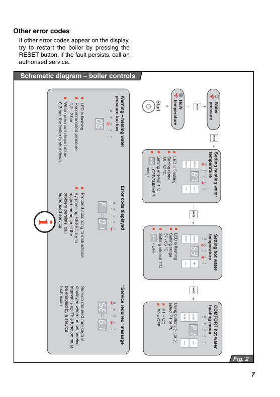
Press and keep depressed the MODE button for 2 seconds and then press the MODE button
repeatedly until the LED under the symbol starts fl ashing. Using the „+“ and „-“
buttons set the hot water temperature to the required value. Setting range is --, 37 to 63°C (in 1°C steps). If you select (--), the boiler will heat only heating water.In the KKO model with an external hot water tank it is possible to set the required hot water temperature in the tank only if an NTC sensor is installed.
Setting heating water temperature
Press and keep depressed the MODE button for 2 seconds and then press the MODE button repeatedly until the LED
under the symbol starts fl ashing. Using the „+“ and „-“ buttons set the heating water temperature to the required value. Setting range is --, 38 to 82°C (in 1°C steps). If you select (--), the boiler will heat only hot water, i.e. it will be working in the so called summer mode.
Displaying heating water temperature
After turning the boiler on with the main switch, the current heating water temperature will appear on the
display. LED under the symbol lights up.
Indicating “hot water tap open”
During hot water tap open, the display shows the required temperature of hot water. If the
boiler is coupled with an external hot water tank with an NTC sensor, then when hot water is running, the current hot water temperature inside the tank is displayed on the screen (after pressing the MODE button). This is indicated by lighting of LED at symbol .
Displaying heating water pressure
Pressing and holding depressed the MODE button will display heating water pressure in the system for about 30 s. The
LED under the symbol lights up
Warning “heating water pressure too low”
When the heating water pressure drops below 0.6 bar or it rises above 2.8 bar, the heating water
pressure appears on the display. The LED under the symbol fl ushes. The boiler is still functional, the pressure must be adjusted to the recommended value 1,2 - 2 bar. When the heating water pressure drops below 0,3 bar, the boiler shuts itself down.

6
Function hot water COMFORT
Press and keep depressed the MODE button for 2 seconds and then press the MODE button
repeatedly until the parameter P0 or P1
Error codes and troubleshooting
Error codes
If a fault is detected, the fault symbol and the error code will appear on the screen in turns.
and error code
The fault is also indicated by lighting up the LED under the symbol .
Boiler overheated – F.20
The boiler has overheated and is automatically shut down, waiting for the temperature to drop. When the temperature drops
down to operating temperature, the boiler will restart itself. If the F.20 error code reappears, call an authorised service.
Not enough water – F.22
There is not enough water in the heating system. The boiler is automatically shut down. Top up water in the
heating circuit (page 10 – Topping up water in the heating system). and then press the RESET button. If the error code reappears, call an authorised service.
Faulty ignition – F.28
When starting the boiler, the burner failed to ignite. Check the gas shutting valve underneath the
boiler and press the RESET button. If the fault persists, call an authorised service.
Please note: The boiler will make fi ve attempts to light itself up and if it fails, fault F.28 will appear on the display.
Need for annual service inspection.
When this
message appears, it is necessary to call an authorised
service and ask
them to carry out an “annual” preventative inspection. This type of message is not factory enabled.
The function can be enabled on request by an authorised service, which will set a service interval. The service interval is
counted in hours, counting the time when
the boiler’s burner is on.
Please note: That a preventative “annual”
inspection has been carried out is indicated by displaying “SE” with one of
the standard parameters appended (e.g.
heating water temperature in the boiler).
appears on the display. Using the „+“ and „-“ buttons select the required COMFORT mode (preheat) parameter. Setting range P0 – OFF, P1 – ON.
Please note: The COMFORT function ensures a permanent pre-heating of hot water in the exchanger, shortening the time before hot water of required temperature starts running out of the tap.
7
Fig. 2
Schematic diagram – boiler controls
Recom
mended p
ressure
1,2
- 2 b
ar
.
When p
ressure
dro
ps b
elo
w
0,3
bar, th
e b
oile
r is s
hut d
ow
n
LE
D is
flash
ing
Se
tting
ran
ge
35
- 87
°C
Se
tting
inte
rval 1
°C
- OF
F/S
UM
ME
Rm
od
e
Pro
ceed a
ccord
ing to
instru
ctio
ns
Se
tting
ran
ge
37
- 63
°CP
1 =
ON
Usin
g b
utto
ns (+
) or (-)
se
lect P
1 o
r P0
P0
= O
FF
- OF
FS
tart
HeW
te
mp
era
ture
Wate
r p
ressu
re
Se
tting
he
atin
g w
ate
r te
mp
era
ture
Se
tting
ho
t wa
ter
tem
pe
ratu
reC
OM
FO
RT
ho
t wa
ter
he
atin
g m
od
e
Wa
rnin
g –
he
atin
g w
ate
r p
res
su
re to
o lo
w
Erro
r co
de
dis
pla
ye
d“S
erv
ice
req
uire
d” m
es
sag
e
By p
ressin
g R
ES
ET, try
to
resta
rt the b
oile
r. If the
pro
ble
m p
ers
ists
, call
auth
oris
ed s
erv
ice
Serv
ice re
quire
d m
essage is
dis
pla
yed w
hen th
e s
et s
erv
ice
inte
rval is
up. T
his
functio
n m
ust
be e
nable
d b
y a
serv
ice
technic
ian
LE
D is
flash
ing
LE
D is
flash
ing
Se
tting
inte
rval 1
°C
Other error codes
If other error codes appear on the display, try to restart the boiler by pressing the RESET button. If the fault persists, call an authorised service.

8
Starting the boiler up
Important: Putting the boiler into operati-on and starting it up for the fi rst time must be done by an authorised service only!
If you wish to start the boiler after it has been put into operation, make sure that:
1. the boiler is connected to power supply;2. all valves underneath the boiler (hot
water, heating water, gas) are opened;3. the heating water pressure is within the
recommended range 1,2 – 2 bar.Turn the main switch (Fig. 1, pos. 1) ON. A few moments later the heating water temperature will appear on the display and the LED under the symbol will light up (Fig. 1, pos. 2). When the burner ignites, the LED under the symbol will light up (Fig.1, pos. 6).
In the event of an emergency boiler shutdown, a fault indicating red LED will light up on the control panel (Fig. 1,
Position 5) and an error message code will appear on the boiler’s display. Unblock the boiler by pressing the RESET button (Fig.1, Position 9). If the emergency shutdown recurs after a short time again, or if the boiler cannot be RESET, call an authorised service organisation.
Turning the boiler off
Turn the main switch (Fig. 1, pos. 1) off.
If the boiler is to remain shut down for a protracted period of time, shut all valves underneath the boiler off (HeW, HoW, gas). When shutting the boiler down, take into consideration the ambient temperature in the given season. If there is a danger that the boiler may freeze, drain the water from the boiler, the heating system and the hot water pipes.
Starting the boiler up and turning it off
Boiler control
Using the boiler without room control unit
When run in this mode, the boiler maintains
the set heating water temperature. No room
control unit is connected, the terminals for its connection must be interconnected with a jumper (standard factory setting).
Setting procedure:
• turn the main switch ON;• set the heating water temperature to the
required value on the control panel.
Using the boiler with room control unit
The boiler maintains the set heating
water temperature. The room control unit connection terminal jumper must be
removed and the room control unit wired
to the terminals. The boiler is turned on
and off to maintained the set temperature in the room in which the control unit is installed. Radiators in this room must not
be equipped with thermostatic valves.
Important: You must set on the boiler
control panel a heating water temperature
(temperature of the water in the system) which will be capable of covering thermal losses of the building even in low outdoor
temperatures.
Please note: Use only control units recommended and sold by PROTHERM
which are designed and tested for the particular type of boiler. If you use a different unit, we cannot guarantee the
boiler’s correct and full functioning.

9
Using the boiler with equithermal control
The boiler changes the heating water temperature as the outdoor temperature changes.
When this type of control is used, it is necessary to install a control unit which has the equithermal control function, Protherm Thermolink B or Thermolink P. In addition, it is necessary to install an outdoor temperature sensor.
Protection against freezing
The boiler has an antifreeze protection system which protects the boiler (but not the heating and the hot water distribution systems) against freezing.
When the heating water temperature inside the boiler drops to 8°C, the pump is switched on, regardless of signal from room control unit and summer-mode setting. When the heating water temperature inside the boiler reaches 10°C, the pump is automatically switched
off. If the heating water temperature inside
the boiler continues to drop, at 5°C the boiler lights itself up and heats the heating water to 35°C.
Important: When the frost protection function is enabled, the three-way valve
switches to the middle position and both
heating water and hot water start to be heated.
Protection of hot water tank against freezing
When the temperature in hot water tank
drops to 10°C, the boiler heats the tank to
15°C. The function is enabled only when the external hot water tank with an NTC sensor is connected.
Protective functions
Pump protection
When the pump has been continuously idle for 23 hours, it is automatically switched on for about 20 seconds, to prevent it from ceasing or clogging due to protracted inactivity.
The boiler is also equipped with a clogging protection system.
Important: This boiler function cannot be disabled.
Two-speed pump
Two-speed pump with automatical switching of the speed is mouted in the boiler. When boiler warm heating water,
pump is runing according to setup of the
parameter on control board. When boiler warm hot water, pump is runing for higher speed.
Please note: Pump runing parameter may be seting up only by an authorised
technician.
Pump run-down
Pump run-down is factory set to 30
seconds for heating of hot water. When
heating a heating water, the run-down is set to 3 minutes. The maximum run-down can be set to 60 minutes.
Important: Room control unit and outdoor sensor must be installed by an authorised service only.
Setting the boiler output
The boiler is factory-set to its maximum output. If necessary, the boiler heating water output can be adjusted as required (in view of the boiler’s features).
Important: Output setting may be chan-ged only by an authorised technician.

10
Important: This boiler function is enabled only when boiler is connected to electrical mains.
Anti-cycling
The boiler features an anti-cycling function. The control board calculate automatically the delay of the next start up of boiler depending on boiler conditions.
Disconnecting the boiler from power supply
Disconnect the boiler from power supply only before service or when the boiler is to be shut down for a protracted time (see Chapter “Switching the boiler off” on page 8). When the boiler is disconnected from power supply, all protection functions are disabled.
Power failure
Power failure will turn the boiler off. When power supply is restored, the boiler will automatically restart itself without losing any of the set operating parameters.
If after power supply restoration the red
LED on the control panel (Fig. 1, pos. 5)
lights up, proceed in accordance with the
Toping up water in the heating system
Water in the heating system (in small quantities) can be topped up through the boiler’s top-up valve (Fig. 3).
When topping up water in the system, the
following conditions must be met:
1. Pressure of the water supplied to the
boiler must be always higher than the water pressure inside the heating system.
instructions in section Starting the boiler and turning if off.
Please note: The boiler may get blocked because of overheating caused by the pump being switched off as a result of the power failure. This fault can be fi xed by pressing the RESET button on the boiler’s control panel. If the fault persists, call an authorised service.
Safety valve
The boiler is equipped with a safety valve which opens when the pressure in the heating system reaches 3 bar. DO NOT TOUCH THE SAFETY VALVE! If the safety valve starts releasing heating water, always turn the boiler off, disconnect it from power supply and call an authorised service organisation. If the heating system repeatedly looses pressure, consult your service organisation.
Important: All the above-mentioned electronic protection functions are enabled only when the boiler is connected to power supply (the power cord plug is inserted into a power socket and the main switch in the ON position (I).
Service and maintenance
2. The boiler must be cold (water
temperature must not exceed 30˚C).
3. Recommended water pressure inside the cold boiler (not more than 30˚C) is 1,2 to 2 bar.

11
Fig. 3
Water top-up system
Warranty and warranty conditions
PROTHERM Lion gas boilers are covered
by warranty defi ned in the Warranty Certi-fi cate, the Service Book and other conditi-
Important: If the water mains pressure were lower or equal to the water pressure inside the heating system, the heating water may run into the water mains, which is forbidden. This danger is reduced by a built-in reverse valve installed downstream the top-up valve.
This notwithstanding, the manufacturer disclaims responsibility for any damages caused by incorrect manipulation with the top-up valve and a failure to abide by the conditions specifi ed above. Such damages and defects are not covered by the boiler’s warranty.
Procedure of topping up heating water to the boiler:
• make sure that the boiler is connected to power supply and the main switch is in the ON position;
• when the heating water pressure showed on the display is below 0.6 bar, the red LED next to the symbol on the boiler’s control panel fl ashes (Fig. 1, Position 4) and the display shows current heating water pressure.
• partially open the top-up valve (Fig. 3). Watch the pressure grow on the boiler’s
display panel;• fi ll the system up until the pressure
reaches the value between 1.2 and 2
bar;
• when the required pressure has been reached, tighten the top-up valves with your hand;
• thoroughly bleed all radiators (the water
must be running out in a continuous stream, free of air bubbles);
• check whether the pressure shown on
the display is within 1.2 and 2 bar. If necessary, add more water into the system.
Cleaning
The boiler cover can be cleaned with a moist cloth and afterwards dried and polished with a dry cloth. Never use abrasive detergents or solvents.
Important: before cleaning the boiler, turn it off with the main switch.
Regular service
To assure trouble-free and safe running of
your boiler, we recommend that you have
the boiler checked and serviced in regular yearly intervals. These inspections are not covered by the boiler’s warranty. The
operations to be done are specifi ed in the
Service Book and must be carried out by an authorised service.
ons specifi ed in the Operation Guide and
Installation Guide (chapters Introduction and Boiler installation).
12
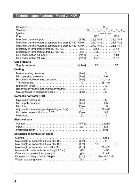
Category . . . . . . . . . . . . . . . . . . . . . . . . . . . . . . . . . . . . . . . . . . . . . . . . . . . . . II2H3P
Version . . . . . . . . . . . . . . . . . . . . . . . . . . . . . . . . . . . . . . . . . . .B23
, B33
, B53
, C13
, C33
, C43
, C53
, C83
Ignition . . . . . . . . . . . . . . . . . . . . . . . . . . . . . . . . . . . . . . . . . . . . . . . . . . . . electronic
Fuel . . . . . . . . . . . . . . . . . . . . . . . . . . . . . . . . . . . . . . . . . . . . . . . . . . .G20 . . . . . . . . . .G31
Max./min. thermal input . . . . . . . . . . . . . . . . . . . . . . . . . [kW]. . . . .25,6 / 4,5 . . . . . .25,5 / 4,5
Max./min. thermal output at temperature drop 80 / 60 °C [kW] . . . .25,0 / 4,2 . . . . . .24,8 / 4,2
Max./min. thermal output at temperature drop 50 / 30 °C [kW] . . . .27,9 / 5,0 . . . . . .26,8 / 4,7
Efficiency at temperature drop 80 / 60 °C . . . . . . . . . . . . [%] . . . . . . .98,1 . . . . . . . . . .97,1
Efficiency at temperature drop 50 / 30 °C . . . . . . . . . . . . [%] . . . . . . . 105 . . . . . . . . . 101,7
Gas consumption (Q max.) . . . . . . . . . . . . . . . . . . . . . . [m3/h] . . . . . 2,7 . . . . . . . . . .1,04
Gas consumption (Q min.) . . . . . . . . . . . . . . . . . . . . . . [m3/h] . . . . .0,48 . . . . . . . . . .0,18
Gas pressure
Supply pressure . . . . . . . . . . . . . . . . . . . . . . . . . . . . . . [mbar] . . . . . . 20 . . . . . . . . . . . 37
Heating
Max. operating pressure . . . . . . . . . . . . . . . . . . . . . . . . [bar]. . . . . . . . . . . . . . 3
Min. operating pressure . . . . . . . . . . . . . . . . . . . . . . . . [bar]. . . . . . . . . . . . . .0,6
Recommended operating pressure . . . . . . . . . . . . . . . . [bar]. . . . . . . . . . . . 1,2 – 2
Thermal range . . . . . . . . . . . . . . . . . . . . . . . . . . . . . . . . . [°C] . . . . . . . . . . . . 35 – 87
Expansion vessel . . . . . . . . . . . . . . . . . . . . . . . . . . . . . . .[l] . . . . . . . . . . . . . . . 10
Boiler water volume (heating water volume) . . . . . . . . . . .[l] . . . . . . . . . . . . . . .2,7
Max. pressure in expansion vessel . . . . . . . . . . . . . . . . [bar]. . . . . . . . . . . . . . 3
Domestic hot water (HW)
Max. supply pressure . . . . . . . . . . . . . . . . . . . . . . . . . . [bar]. . . . . . . . . . . . . . 6
Min. supply pressure . . . . . . . . . . . . . . . . . . . . . . . . . . . [bar]. . . . . . . . . . . . . .0,5
Min. flow . . . . . . . . . . . . . . . . . . . . . . . . . . . . . . . . . . . . [l/min] . . . . . . . . . . . . .1,5
Adjustable thermal range (depending on flow) . . . . . . . . [°C] . . . . . . . . . . . . 37 – 63
Hot water consumption at Δt 30˚C . . . . . . . . . . . . . . . . [l/min] . . . . . . . . . . . . 11,8
Max. flow . . . . . . . . . . . . . . . . . . . . . . . . . . . . . . . . . . . . . .[l] . . . . . . . . . . . . . . . 10
Electrical data
Voltage . . . . . . . . . . . . . . . . . . . . . . . . . . . . . . . . . . . . . [V/Hz] . . . . . . . . . . . 230/50
Input . . . . . . . . . . . . . . . . . . . . . . . . . . . . . . . . . . . . . . . . [W] . . . . . . . . . . . . . 123Protection cover . . . . . . . . . . . . . . . . . . . . . . . . . . . . . . . . . . . . . . . . . . . . . . . IP45
Extraction of combustion gases
Method . . . . . . . . . . . . . . . . . . . . . . . . . . . . . . . . . . . . . . . . . . . . . . . . . . . . . . . turbo
Max. length of concentric flue ø 60 / 100 . . . . . . . . . . . . [Em] . . . . . . . . . . . . . 9
Max. length of concentric flue ø 80 / 125 . . . . . . . . . . . . [Em] . . . . . . 13 . . . . . . . . . . . . 9
Max. length of separate flue ø 80 + 80 . . . . . . . . . . . . . . [Em] . . . . . . . . . . . 20 + 20
Noise level (1 m from boiler at height 1,5 m) . . . . . . . . . .[dB] . . . . . . . . . . . . .do 55Combustion gasses flow by weight . . . . . . . . . . . . . . . . .[g/s] . . . . . . . . . . . . .11,49
Dimensions - height / width / depth . . . . . . . . . . . . . . . . [mm] . . . . . . . . 780 / 450 / 323
Weight excluding water . . . . . . . . . . . . . . . . . . . . . . . . . . [kg] . . . . . . . . . . . . . . 44
Technical specifications - Model 24 KKV

13
Category . . . . . . . . . . . . . . . . . . . . . . . . . . . . . . . . . . . . . . . . . . . . . . . . . . . . . II2H3P
Version . . . . . . . . . . . . . . . . . . . . . . . . . . . . . . . . . . . . . . . . . . .B23
, B33
, B53
, C13
, C33
, C43
, C53
, C83
Ignition . . . . . . . . . . . . . . . . . . . . . . . . . . . . . . . . . . . . . . . . . . . . . . . . . . . . electronic
Fuel . . . . . . . . . . . . . . . . . . . . . . . . . . . . . . . . . . . . . . . . . . . . . . . . . . . G20 . . . . . . . . . .G31
Max./min. thermal input . . . . . . . . . . . . . . . . . . . . . . . . . [kW]. . . . . 29,6 / 5,3 . . . . . .29,5 / 5,2
Max./min. thermal output at temperature drop 80 / 60 °C [kW] . . . . 29,0 / 5,0 . . . . . .28,7 / 4,9
Max./min. thermal output at temperature drop 50 / 30 °C [kW] . . . . 31,7 / 5,7 . . . . . .30,6 / 5,6
Efficiency at temperature drop 80 / 60 °C . . . . . . . . . . . . [%] . . . . . . . 98,1 . . . . . . . . . .97,1
Efficiency at temperature drop 50 / 30 °C . . . . . . . . . . . . [%] . . . . . . . 104 . . . . . . . . . 101,4
Gas consumption (Q max.) . . . . . . . . . . . . . . . . . . . . . . [m3/h] . . . . . . 3,13 . . . . . . . . . .1,21
Gas consumption (Q min.) . . . . . . . . . . . . . . . . . . . . . . [m3/h] . . . . . . 0,56 . . . . . . . . . .0,21
Gas pressure
Supply pressure . . . . . . . . . . . . . . . . . . . . . . . . . . . . . . [mbar] . . . . . . .20 . . . . . . . . . . . 37
Heating
Max. operating pressure . . . . . . . . . . . . . . . . . . . . . . . . [bar]. . . . . . . . . . . . . . 3
Min. operating pressure . . . . . . . . . . . . . . . . . . . . . . . . [bar]. . . . . . . . . . . . . .0,6
Recommended operating pressure . . . . . . . . . . . . . . . . [bar]. . . . . . . . . . . . 1,2 – 2
Thermal range . . . . . . . . . . . . . . . . . . . . . . . . . . . . . . . . . [°C] . . . . . . . . . . . . 35 – 87
Expansion vessel . . . . . . . . . . . . . . . . . . . . . . . . . . . . . . .[l] . . . . . . . . . . . . . . . 10
Boiler water volume (heating water volume) . . . . . . . . . . .[l] . . . . . . . . . . . . . . .2,7
Max. pressure in expansion vessel . . . . . . . . . . . . . . . . [bar]. . . . . . . . . . . . . . 3
Domestic hot water (HW)
Max. supply pressure . . . . . . . . . . . . . . . . . . . . . . . . . . [bar]. . . . . . . . . . . . . . 6
Min. supply pressure . . . . . . . . . . . . . . . . . . . . . . . . . . . [bar]. . . . . . . . . . . . . .0,5
Min. flow . . . . . . . . . . . . . . . . . . . . . . . . . . . . . . . . . . . . [l/min] . . . . . . . . . . . . .1,5
Adjustable thermal range (depending on flow) . . . . . . . . [°C] . . . . . . . . . . . . 37 – 63
Hot water consumption at Δt 30˚C . . . . . . . . . . . . . . . . [l/min] . . . . . . . . . . . . . 14
Max. flow . . . . . . . . . . . . . . . . . . . . . . . . . . . . . . . . . . . . . .[l] . . . . . . . . . . . . . . . 12
Electrical data
Voltage . . . . . . . . . . . . . . . . . . . . . . . . . . . . . . . . . . . . . [V/Hz] . . . . . . . . . . . 230/50
Input . . . . . . . . . . . . . . . . . . . . . . . . . . . . . . . . . . . . . . . . [W] . . . . . . . . . . . . . 125Protection cover . . . . . . . . . . . . . . . . . . . . . . . . . . . . . . . . . . . . . . . . . . . . . . . IP45
Extraction of combustion gases
Method . . . . . . . . . . . . . . . . . . . . . . . . . . . . . . . . . . . . . . . . . . . . . . . . . . . . . . . turbo
Max. length of concentric flue ø 60 / 100 . . . . . . . . . . . . [Em] . . . . . . . . . . . . . 9
Max. length of concentric flue ø 80 / 125 . . . . . . . . . . . . [Em] . . . . . . .13 . . . . . . . . . . . . 9
Max. length of separate flue ø 80 + 80 . . . . . . . . . . . . . . [Em] . . . . . . . . . . . 20 + 20
Noise level (1 m from boiler at height 1,5 m) . . . . . . . . . .[dB] . . . . . . . . . . . . .do 55Combustion gasses flow by weight . . . . . . . . . . . . . . . . .[g/s] . . . . . . . . . . . . .13,36
Dimensions - height / width / depth . . . . . . . . . . . . . . . . [mm] . . . . . . . . 780 / 450 / 323
Weight excluding water . . . . . . . . . . . . . . . . . . . . . . . . . . [kg] . . . . . . . . . . . . . . 44
Technical specifications - Model 28 KKV
14
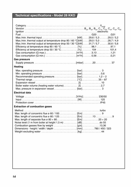
Category . . . . . . . . . . . . . . . . . . . . . . . . . . . . . . . . . . . . . . . . . . . . . . . . . . . . . II2H3P
Version . . . . . . . . . . . . . . . . . . . . . . . . . . . . . . . . . . . . . . . . . . .B23
, B33
, B53
, C13
, C33
, C43
, C53
, C83
Ignition . . . . . . . . . . . . . . . . . . . . . . . . . . . . . . . . . . . . . . . . . . . . . . . . . . . . electronic
Fuel . . . . . . . . . . . . . . . . . . . . . . . . . . . . . . . . . . . . . . . . . . . . . . . . . . . G20 . . . . . . . . . .G31
Max./min. thermal input . . . . . . . . . . . . . . . . . . . . . . . . . [kW]. . . . . 29,6 / 5,3 . . . . . .29,5 / 5,2
Max./min. thermal output at temperature drop 80 / 60 °C [kW] . . . . 29,0 / 5,0 . . . . . .28,7 / 4,9
Max./min. thermal output at temperature drop 50 / 30 °C [kW] . . . . 31,7 / 5,7 . . . . . .30,6 / 5,6
Efficiency at temperature drop 80 / 60 °C . . . . . . . . . . . . [%] . . . . . . . 98,1 . . . . . . . . . .97,1
Efficiency at temperature drop 50 / 30 °C . . . . . . . . . . . . [%] . . . . . . . 104 . . . . . . . . . 101,4
Gas consumption (Q max.) . . . . . . . . . . . . . . . . . . . . . . [m3/h] . . . . . . 3,13 . . . . . . . . . .1,21
Gas consumption (Q min.) . . . . . . . . . . . . . . . . . . . . . . [m3/h] . . . . . . 0,56 . . . . . . . . . .0,21
Gas pressure
Supply pressure . . . . . . . . . . . . . . . . . . . . . . . . . . . . . . [mbar] . . . . . . .20 . . . . . . . . . . . 37
Heating
Max. operating pressure . . . . . . . . . . . . . . . . . . . . . . . . [bar]. . . . . . . . . . . . . . 3
Min. operating pressure . . . . . . . . . . . . . . . . . . . . . . . . [bar]. . . . . . . . . . . . . .0,6
Recommended operating pressure . . . . . . . . . . . . . . . . [bar]. . . . . . . . . . . . 1,2 – 2
Thermal range . . . . . . . . . . . . . . . . . . . . . . . . . . . . . . . . . [°C] . . . . . . . . . . . . 35 – 87
Expansion vessel . . . . . . . . . . . . . . . . . . . . . . . . . . . . . . .[l] . . . . . . . . . . . . . . . 10
Boiler water volume (heating water volume) . . . . . . . . . . .[l] . . . . . . . . . . . . . . .2,7
Max. pressure in expansion vessel . . . . . . . . . . . . . . . . [bar]. . . . . . . . . . . . . . 3
Electrical data
Voltage . . . . . . . . . . . . . . . . . . . . . . . . . . . . . . . . . . . . . [V/Hz] . . . . . . . . . . . 230/50
Input . . . . . . . . . . . . . . . . . . . . . . . . . . . . . . . . . . . . . . . . [W] . . . . . . . . . . . . . 125
Protection cover . . . . . . . . . . . . . . . . . . . . . . . . . . . . . . . . . . . . . . . . . . . . . . . IP45
Extraction of combustion gases
Method . . . . . . . . . . . . . . . . . . . . . . . . . . . . . . . . . . . . . . . . . . . . . . . . . . . . . . . turboMax. length of concentric flue ø 60 / 100 . . . . . . . . . . . . [Em] . . . . . . . . . . . . . 9
Max. length of concentric flue ø 80 / 125 . . . . . . . . . . . . [Em] . . . . . . .13 . . . . . . . . . . . . 9Max. length of separate flue ø 80 + 80 . . . . . . . . . . . . . . [Em] . . . . . . . . . . . 20 + 20
Noise level (1 m from boiler at height 1,5 m) . . . . . . . . . .[dB] . . . . . . . . . . . . .do 55Combustion gasses flow by weight . . . . . . . . . . . . . . . . .[g/s] . . . . . . . . . . . . .13,36
Dimensions - height / width / depth . . . . . . . . . . . . . . . . [mm] . . . . . . . . 780 / 450 / 323Weight excluding water . . . . . . . . . . . . . . . . . . . . . . . . . . [kg] . . . . . . . . . . . . . . 44
Technical specifications - Model 28 KKO
15
780
780
323323450450
217217233233
36.2
36.2
6565 ( )110.4110.4 26.2
26.2
43.7
43.7
28281717
217217
121.5
121.5
93.5
93.5
200200
51.551.5
6060
64.564.5656593.693.6
1 2 4 5 67 3
ø
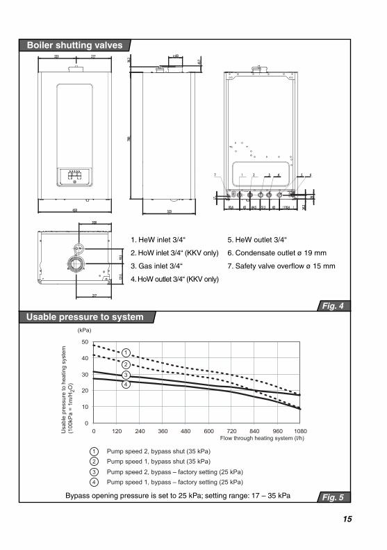
Boiler shutting valves
Připojovací rozměry kotleUsable pressure to system
Fig. 4
Fig. 5
1. HeW inlet 3/4“ 5. HeW outlet 3/4“
2. HoW inlet 3/4“ (KKV only) 6. Condensate outlet ø 19 mm
3. Gas inlet 3/4“ 7. Safety valve overflow ø 15 mm
4. HoW outlet 3/4“ (KKV only)
Bypass opening pressure is set to 25 kPa; setting range: 17 – 35 kPa
0
10
20
30
40
50
0 120 240 360 480 600 720 840 960 1080
Pump speed 2, bypass shut (35 kPa)
Usa
ble
pres
sure
to h
eatin
g sy
stem
(100
kPa
= 1m
/H2O
)
(kPa)
Flow through heating system (l/h)
1
2
3
4
1
2 Pump speed 1, bypass shut (35 kPa)3 Pump speed 2, bypass – factory setting (25 kPa)4 Pump speed 1, bypass – factory setting (25 kPa)

16
Function diagram of boilers 24 / 28 KKV
Fig. 6
21 17 1820 1619
3
kPa
M
1
2
3
4
56
7
8
910
11
12
1314
15
222324
25
26
27
28
29
30
31
1.combustion gas extraction 11. HoW fl ow sensor 22. bypass
2. air bleeding valve 12. draining valve 23. HoW NTC sensor
3. expansion vessel 13. backfl ow valve 24. HeW pressure sensor
4. exchanger 14. top-up valve 25. trap
5. pump air bleeding valve 15. fi lter 26. HoW exchanger fi lter
6. pump 16. HeW inlet 27. gas valve
7. safety valve 17. HoW inlet 28. fan
8. NTC sensor of return HeWj 18. gas inlet 29. burner
9. 3-way valve 19. HoW outle 30. HeW temperature NTC sensor
10. HoW exchanger 20. HeW outlet 31. air supply
21. condensate drainage

17
Function diagram of boiler 28 KKO
Fig. 7
kPa
17
18
19
20
21
22
23
24
25
1
2
3
4
56
7
8
9
10
16 12121315 111414
1.combustion gas extraction 10. draining valve 19. trap
2. air bleeding valve 11. HeW inlet 20. fi lter *
3. expansion vessel 12. HeW inlet into the tank* 21. gas valve
4. exchanger 13. gas inlet 22. fan
5. pump air bleeding valve 14. HeW outlet from the tank * 23. burner
6. pump 15. HeW outlet 24. HeW temperature NTC sensor
7. safety valve 16. condensate drainage 25. air supply
8. NTC sensor of return HeW 17. bypass
9. case for installation of 3-way valve 18. HeW pressure sensor
* used only when hot water tank is connected
18
Fig. 8
Zone
Installation instructionsInstallation instructions
Introduction
The Lion boiler is compatible with standard types of hot water heating systems and heating radiators, except systems with an open expansion vessel.
Important: Lion boilers must be put into operation by an authorised organisation only, according to Czech Bureau of Occupational Safety and Czech Mining Inspectorate Notice No. 21/1979 (in the wording of Public Notice No. 554/1990).
The boiler must be put into operation and warranty and post-warranty service performed by the manufacturer’s contracted service organisation which meets the above specifi ed requirements.
Important: The technician who puts the boiler into service must show the user all boiler functions, its controls, and if necessary explain anything the user does not understand in the User’s Guide which is part of the boiler delivery.
The boiler is designed to work in an
normal AA5/AB5 environment according
to STN 33 2000-3 and STN 33 2000-5-51 (i.e. within temperature range +5 to +40°C, humidity depending on temperature, not
exceeding 85%).
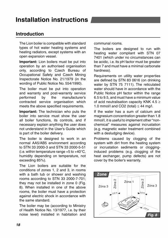
The Lion boilers are suitable for the
conditions of zones 1, 2 and 3, in rooms with a bath tub or shower and washing rooms according to STN 33 2000-7-701;
they may not be installed in zone 0 (Fig.
8). When installed in one of the above rooms, the boiler must have a protection against electric shock in accordance with
the same standard.
The boiler may be (according to Ministry
of Health Notice No. 13/1977, i.e. by their noise level) installed in habitation and
communal rooms.
The boilers are designed to run with heating water compliant with STN 07 7401 (which under no circumstances can be acidic, i.e. its pH factor must be greater than 7 and must have a minimal carbonate hardness).
Requirements on utility water properties are defi ned by STN 83 0616 (on drinking water by STN 75 7111). The reticulated water should have in accordance with the Public Notice pH factor within the range 6.5 to 9.5, and must have a minimum value of acid neutralisation capacity KNK 4.5 ≥ 1.0 mmol/l and CO2 (total) ≤ 44 mg/l.
If the water has a sum of calcium and magnesium concentration greater than 1.8 mmol/l, it is useful to implement other “non-chemical” measures against incrustation (e.g. magnetic water treatment combined with a desludging device).
Problems caused by clogging of the system with dirt from the heating system or incrustation sediments or clogging-
induced problems (e.g. clogging of the
heat exchanger, pump defects) are not cover by the boiler’s warranty.
19
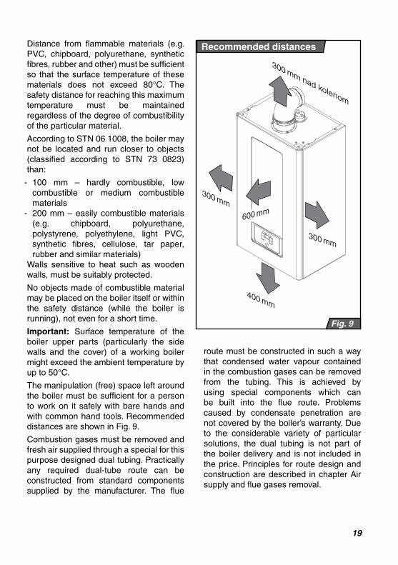
Distance from fl ammable materials (e.g. PVC, chipboard, polyurethane, synthetic fi bres, rubber and other) must be suffi cient so that the surface temperature of these materials does not exceed 80°C. The safety distance for reaching this maximum temperature must be maintained regardless of the degree of combustibility of the particular material.
According to STN 06 1008, the boiler may not be located and run closer to objects (classifi ed according to STN 73 0823) than:
- 100 mm – hardly combustible, low combustible or medium combustible materials
- 200 mm – easily combustible materials (e.g. chipboard, polyurethane, polystyrene, polyethylene, light PVC, synthetic fi bres, cellulose, tar paper, rubber and similar materials)
Walls sensitive to heat such as wooden walls, must be suitably protected.
No objects made of combustible material may be placed on the boiler itself or within the safety distance (while the boiler is running), not even for a short time.
Important: Surface temperature of the boiler upper parts (particularly the side walls and the cover) of a working boiler
might exceed the ambient temperature by
up to 50°C.
The manipulation (free) space left around the boiler must be suffi cient for a person to work on it safely with bare hands and
with common hand tools. Recommended
distances are shown in Fig. 9.
Combustion gases must be removed and
fresh air supplied through a special for this purpose designed dual tubing. Practically any required dual-tube route can be
constructed from standard components
supplied by the manufacturer. The fl ue
300 mm nad kolenom
600 mm
400 mm
300 mm
300 mm
Fig. 9
Recommended distances
route must be constructed in such a way that condensed water vapour contained in the combustion gases can be removed
from the tubing. This is achieved by
using special components which can be built into the fl ue route. Problems caused by condensate penetration are
not covered by the boiler’s warranty. Due
to the considerable variety of particular solutions, the dual tubing is not part of the boiler delivery and is not included in
the price. Principles for route design and
construction are described in chapter Air supply and fl ue gases removal.

20
Fig. 10
1
2
3
6
5 4
7
8
14
9 10
11
12
15
16
17
18
13
Content of delivery
Completeness of delivery

21
Content of the boiler delivery
PROTHERM Lion 24 KKV, 28 KKV and 28 KKO boilers are supplied completely assembled and functionally tested.
The delivery contains (Fig. 10):
1. Boiler
2. Combustion gases exhaust adapter
3. Screws - 3 pieces
4. Mounting bar
5. Wall plugs - 3 pieces
6. Screw - 3 pieces
7. Boiler connection end pieces - 5 pie-ces
8. Seal - 5 pieces
9. Hot water fi lter
10. Flow restrictor with sealing ring
11. Top-up valve control lever
12. Screw - 1 piece
13. Hose for condensate removal
14. User’s Guide
15. Warranty Certifi cate
16. List of service centres
17. Service Book
Special accessories
The following special accessories can be ordered as required:
1. Connection ramp, Order No. 0020038446 (Fig. 11)
2. Thermolink S room control unit – two-stage control, Order No. 0020035407
3. Thermolink B room control unit – eBus control, Order No. 0020035406, or Thermolink P - eBus control, Order No. 0020035408
4. Outdoor sensor for equithermal control, Order No. 0020041356
5. Connection kit for coupling a hot water tank to the boiler (model KKO only)
6. Exhaust fl ue components described in this User’s Guide on page 32 - 39
Fig. 11
Connection ramp
64,5
129,5
116,5
246
65
51,5
65
G3/4
G3/4
G3/4
G1/2
G1/2
22
Distribution pipes
Nominal pipe internal diameter is chosen in the usual way based on the pump characteristic. Distribution pipes are designed according to the requirements on system performance, not according to the boiler’s maximum output. The system must allow suffi cient fl ow so that the temperature difference between the supply and the return pipe is smaller than or equal to 20°C. Minimum fl ow must be 400 l/h.The piping system must be constructed to prevent air bubbles from developing, making permanent bleeding of the system easier. Vents should be situated on all high points of the system and on all radiators.It is recommended to install upstream the boiler a system of heating water, hot water and gas shutting valves.We recommend that you install on the lowest point of the heating system a drainage valve which will also dub as a heating system top-up valve.Before fi nal installation of the boiler, the heating distribution system pipes must be
fl ushed a few times with pressurised water.
In old, already used systems, the fl ushing must be done in opposite direction to the heating water fl ow.
Important: Before connecting the boiler to the heating system, remove the plastic
plugs inserted in all connection necks.
Heating system cleanliness
Before installing a new boiler, it is essential to clean the system thoroughly. In old
systems it is necessary to remove all
sludge settled at the bottom of the heating radiators (particularly in gravity systems).
In new systems it is necessary to remove all conservation material which majority of radiator manufacturers use.
It is recommended to install upstream the boiler (i.e. to the heating water return pipe) a sludge trap. The sludge trap should be constructed in such a way that it is easy to empty in regular time intervals without having to drain a lot of water from the heating system. The trap can be combined with a fi lter, but a fi lter with a sieve on its own will not provide suffi cient protection. The fi lter and the sludge trap must be checked and cleaned regularly.
Heating water circulation in the system
Although the boiler is equipped with a bypass, we recommend to design the heating system so that the heating water can fl ow through at least some of the radiators all the time.Please note: If the boiler is connected to underfl oor heating, we recommend to install a in the heating system a safety valve against overheating.
Using antifreeze
We do not recommend to use antifreeze, because of their unsuitable properties for the boiler. It is mainly their reduced heat
transfer, large volume expansion, aging
and, more than anything else, potential damage of the heating water heat exchangers.
Important: Defects caused by using
antifreeze are not covered by the boiler’s warranty.
Thermostatic radiator valves
If a room control unit is installed, at least
one of the radiators in the reference
room must be without a thermostatic valve. For better temperature comfort, we recommend to leave all radiators in the
reference room without a thermostatic valve.
Preparing for installation

23
Domestic hot water system
Pressure in the hot water system must be within the range of 1 to 6 bar. If the pressure exceeds 6 bar, a pressure reduction valve must be fi tted on the supply side,
combined with a safety valve.
In areas with very hard water we recommend to implement suitable measures to reduce the water hardness.
Fig. 12
K
O
A
L
P
S
T
R
M
W
Mounting the boiler
24
Installing the boiler
Mounting the boiler
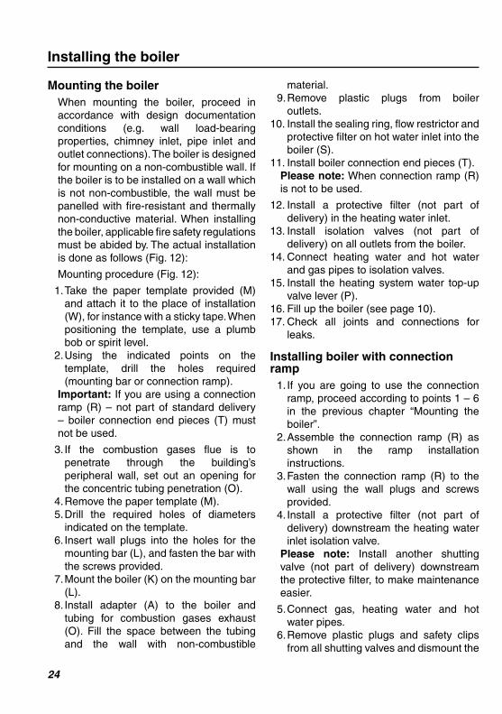
When mounting the boiler, proceed in accordance with design documentation conditions (e.g. wall load-bearing properties, chimney inlet, pipe inlet and outlet connections). The boiler is designed for mounting on a non-combustible wall. If the boiler is to be installed on a wall which is not non-combustible, the wall must be panelled with fi re-resistant and thermally non-conductive material. When installing the boiler, applicable fi re safety regulations must be abided by. The actual installation is done as follows (Fig. 12):
Mounting procedure (Fig. 12):
1. Take the paper template provided (M) and attach it to the place of installation (W), for instance with a sticky tape. When positioning the template, use a plumb bob or spirit level.
2. Using the indicated points on the template, drill the holes required (mounting bar or connection ramp).
Important: If you are using a connection
ramp (R) – not part of standard delivery – boiler connection end pieces (T) must not be used.
3. If the combustion gases fl ue is to
penetrate through the building’s
peripheral wall, set out an opening for the concentric tubing penetration (O).
4. Remove the paper template (M).
5. Drill the required holes of diameters
indicated on the template.6. Insert wall plugs into the holes for the
mounting bar (L), and fasten the bar with
the screws provided.
7. Mount the boiler (K) on the mounting bar (L).
8. Install adapter (A) to the boiler and
tubing for combustion gases exhaust (O). Fill the space between the tubing and the wall with non-combustible
material.9. Remove plastic plugs from boiler
outlets.10. Install the sealing ring, fl ow restrictor and
protective fi lter on hot water inlet into the boiler (S).
11. Install boiler connection end pieces (T). Please note: When connection ramp (R) is not to be used.
12. Install a protective fi lter (not part of delivery) in the heating water inlet.
13. Install isolation valves (not part of delivery) on all outlets from the boiler.
14. Connect heating water and hot water and gas pipes to isolation valves.
15. Install the heating system water top-up valve lever (P).
16. Fill up the boiler (see page 10). 17. Check all joints and connections for
leaks.
Installing boiler with connection ramp
1. If you are going to use the connection ramp, proceed according to points 1 – 6 in the previous chapter “Mounting the
boiler”.
2. Assemble the connection ramp (R) as shown in the ramp installation instructions.
3. Fasten the connection ramp (R) to the
wall using the wall plugs and screws provided.
4. Install a protective fi lter (not part of
delivery) downstream the heating water
inlet isolation valve.Please note: Install another shutting valve (not part of delivery) downstream
the protective fi lter, to make maintenance
easier.
5. Connect gas, heating water and hot
water pipes.6. Remove plastic plugs and safety clips
from all shutting valves and dismount the
25
connection ramp (R) support frame.7. Install the sealing ring, fl ow restrictor
and protective fi lter (S) in the hot water inlet to the boiler.
8. Fasten the boiler (K) to the wall and
connect it to isolation valves.9. Install adapter (A) and combustion gases
exhaust tubing (O). Fill up the space between the tubing and the wall with non-combustive material.
10. Install the heating system top-up water valve lever (P).
11. Fill up the boiler (see page 10). 12. Check all joints and connections for
leaks.
Connecting the boiler to heating water, hot water and gas pipes
The boiler connection end pieces must not be subjected to any forces from the heating water, domestic hot water or gas piping system. This requires accurate positioning of all connection pipes, vertically (height) as well as the distance from the wall and mutual distance between inlets and outlets.
We recommend to design the heating system in such a way that when making repairs, it will be possibly to drain the
whole heating system from the boiler.
In case of reconstructions, in unfavourable
building dispositions, etc., it is possible to
connect the boiler to the heating system, the domestic hot water system as well as the gas supply by fl exible hoses, but only
those designed for that purpose. Flexible
components should be as short as possible, must be protected against mechanical and chemical loads and damage, and must be
replaced with new ones before the end of
their useful life cycle or reliability to meet their nominal specifi cations (as stated by their manufacturers).Please note: The manufacturer
recommends to install an external fi lter into the water inlet to the boiler.
Operating pressure in the heating system
The heating system (measured on the boiler) must be fi lled in at least to the hydraulic pressure of 1 bar (corresponds to the hydrostatic water column of 10 m). We recommend that you maintain the pressure within the range 1.2 – 2 bar. The
expansion vessel capacity is suffi cient for
up to 110 l of heating water in the heating system (at temperature 75°C).
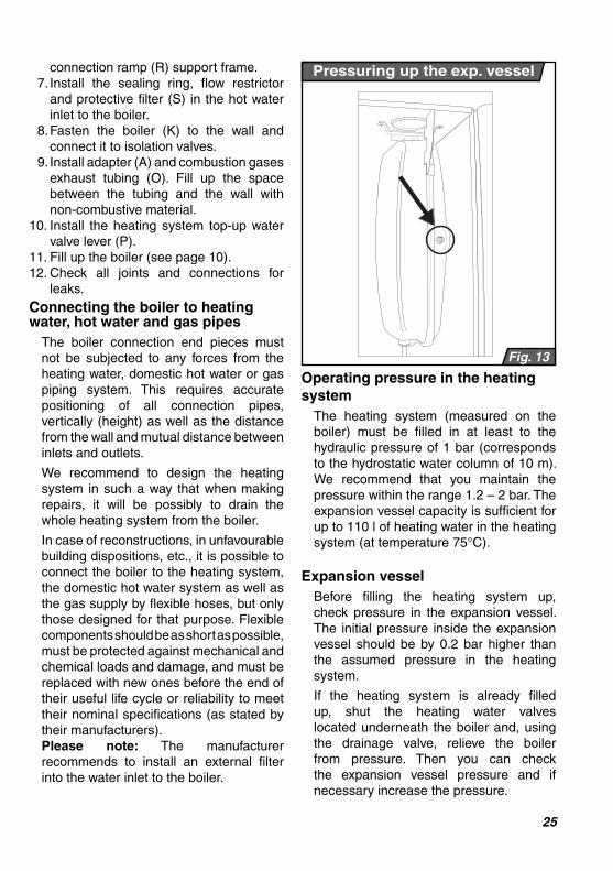
Expansion vessel
Before fi lling the heating system up,
check pressure in the expansion vessel.
The initial pressure inside the expansion vessel should be by 0.2 bar higher than the assumed pressure in the heating
system.
If the heating system is already fi lled up, shut the heating water valves
located underneath the boiler and, using the drainage valve, relieve the boiler from pressure. Then you can check
the expansion vessel pressure and if necessary increase the pressure.
Pressuring up the exp. vessel
Fig. 13

26
Fig. 14
Safety valve
Fig. 15
Bleeding valve
The expansion vessel pressurising valve is situated on the right from the pump (Fig. 13).
Important: Make sure that the expansion vessel capacity is suffi cient for the volume of water in the heating system (see installation design documentation).
Safety valve
The system safety valve is situated at the bottom of the boiler on the left side of the hydraulic group (Fig. 14). When the maximum pressure in the system is exceeded, water or steam can be discharged through the safety valve, therefore we recommend that you attach a hose to the safety valve neck, discharging the water into the building’s waste water system.
Important: Under no circumstances may anyone manipulate with the safety valve while the boiler is in operation. It is also forbidden to use the safety valve for draining water from the boiler or from the heating system. Problems caused by the valve being clogged with dirt from the
heating system are not covered by the boiler’s warranty.
Connecting gas supply
The Lion boilers are designed to be fuelled
by natural gas of nominal pressure in the
gas mains 2 kPa, for which the calorifi c value is most commonly stated to be within the range of 9 and 10 kWh/cu.m.
Indoor gas distribution pipes and a gas
meter must be sized adequately, taking into account also the user’s other gas appliances.
All gas distribution pipes must be installed
in accordance with STN EN 1775.
Important: We recommend to connect
the gas supply using a pipe union with the slip-over nut screwed onto the pipe over a
corresponding sealing ring (see the boiler delivery).
After completing the gas supply connection to the boiler, the coupling must be thoroughly checked for potential
gas leaks.
Toping the boiler water up
The procedure of toping up water in the
boiler is described in the part “Operating
instructions – Service/Maintenance”.
Important: Make sure that during the toping-up procedure as well as when the boiler is running, the automatic vent cap is
loosened (Fig. 15).
27
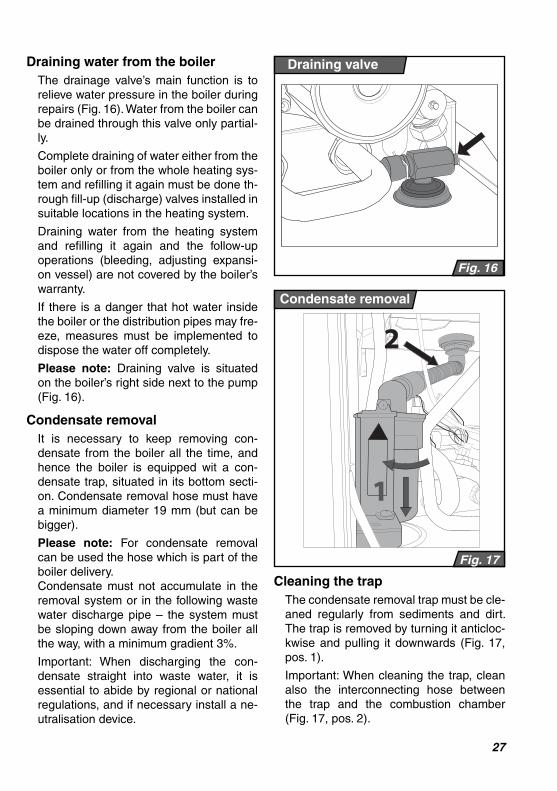
Draining water from the boiler
The drainage valve’s main function is to relieve water pressure in the boiler during repairs (Fig. 16). Water from the boiler can be drained through this valve only partial-ly.
Complete draining of water either from the boiler only or from the whole heating sys-tem and refi lling it again must be done th-rough fi ll-up (discharge) valves installed in suitable locations in the heating system.
Draining water from the heating system and refi lling it again and the follow-up operations (bleeding, adjusting expansi-on vessel) are not covered by the boiler’s warranty.
If there is a danger that hot water inside the boiler or the distribution pipes may fre-eze, measures must be implemented to dispose the water off completely.
Please note: Draining valve is situated on the boiler’s right side next to the pump (Fig. 16).
Condensate removal
It is necessary to keep removing con-
densate from the boiler all the time, and hence the boiler is equipped wit a con-densate trap, situated in its bottom secti-
on. Condensate removal hose must have
a minimum diameter 19 mm (but can be bigger).
Please note: For condensate removal can be used the hose which is part of the
boiler delivery.
Condensate must not accumulate in the removal system or in the following waste water discharge pipe – the system must
be sloping down away from the boiler all
the way, with a minimum gradient 3%.
Important: When discharging the con-
densate straight into waste water, it is essential to abide by regional or national regulations, and if necessary install a ne-utralisation device.
Cleaning the trap
The condensate removal trap must be cle-
aned regularly from sediments and dirt. The trap is removed by turning it anticloc-kwise and pulling it downwards (Fig. 17,
pos. 1).
Important: When cleaning the trap, clean
also the interconnecting hose between the trap and the combustion chamber (Fig. 17, pos. 2).
Condensate removal
Fig. 17
2
1
Draining valve
Fig. 16

28
Air supply and fl ue gases removal
Method C33
Fig. 19
Fig. 18
Method C13
Combustion gasses exhaust and combustion air supply must be constructed from for this purpose designed dual tubing, which is an essential accessory to the boiler. The dual tubing is supplied as extra accessories. Because of the numerous possible topologies and components used, the specifi c route must be part of the building’s exhaust fl ue design documentation.
Horizontal tubing sections must have a gradient allowing water condensate to run towards the boiler or to special condensate removal components. This is achieved by combining elbows with straight components, which will result in a gentle slope of the straight section.
Condensate removal components should be whenever possible installed as close to the combustion gases outlet neck as possible. Defects caused by condensate penetration are not covered by the boiler’s warranty.
Air supply/combustion gases removal methods (according to STN EN 483) and permitted tube lengths
Unless stated for the following dual tube route design methods and their termination outlets otherwise, the tube lengths (from the boiler connection point to the termination outlet) must be as specifi ed in the technical specifi cations table.
Please note: As 1 Em is regarded either 1 m of straight section or one 90° elbow.
The following methods of air supply and combustion gases removal are permitted for this boiler:
Method C13
– horizontal routes with hori-zontal termination outlets discharging to free space.
When using separate tubing (80+80 mm) in horizontal routes with horizontal termination outlets, the air supply inlet
and the combustion gasses outlet from the same boiler must be situated inside a square of a 0.5 m side.
An example of a dual horizontal tubing route – method C13 (according to STN EN 483) is illustrated in Fig. 18.
Method C33
– vertical routes with vertical termination outlets into free space. For separate tubing termination outlets, the same applies as for method C13. An example of a dual vertical tubing route – method C33 (according to STN EN 483) is illustrated in Fig. 19.
Method C43
– connection to common dual chimneys. Dual tubing from each boiler
29
(individual routes) may be terminated in a common chimney; the chimney’s transportation suffi ciency is assessed from the data stated by the manufacturer of the chimney fl ue used. If the routes are terminated in the chimney in mutually perpendicular directions, the minimum vertical distance between them must be 0.45 m. If the routes are terminated in the chimney from opposite directions, the minimum vertical distance between them must be 0.6 m. Outlets of routes terminated in a common dual chimney must never be fi tted with end pieces (used in routes discharging to free space)! Both route sections (the outside – air, and the inside – combustion gases) must be safely inserted into the chimney inlet, but not too deep, so that it does not form an obstacle to the fl owing combustion gases or air.
It is essential that the tubing (chimney) of the combustion gases branch is capable to withstand temperatures up to 120°C and is suffi ciently sealed and resistant against physical and chemical effects (particularly combustion gases)
In this case the concentric tubing route must not exceed the length specifi ed in the technical specifi cations table.
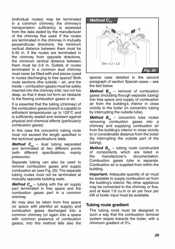
Method C53
– dual tubing separated and terminated at two different points (with different specifi cations, mainly pressures).
Separate tubing can also be used to remove combustion gases and supply combustion air (see Fig. 20). The separate tubing routes must not be terminated at mutually opposite building walls.
Method C83
– tubing with the air supply part terminated in free space and the combustion gases part in a common chimney.
Air may also be taken from free space (or space with plentiful air supply) and combustion gases discharged into a common chimney (or again into a space with common presence of combustion gases). Into this method falls also the
special case detailed in the second paragraph of section Special cases – see the text below.
Method B23
– removal of combustion gases (including through separate tubing) into free space and supply of combustion air from the building’s interior in close vicinity to the boiler (in concentric tubing by interrupting the outside tube).
Method B33
– concentric tube routes removing combustion gases into a chimney and supplying combustion air from the building’s interior in close vicinity to or considerable distance from the boiler (by interrupting the outside part of the tubing).
Method B53
– tubing route constructed of components which are listed in the manufacturer’s documentation. Combustion gases tube is separate. Combustion air is supplied from within the building.
Important: Adequate quantity of air must be available to supply combustion air from the building’s interior. No other appliance may be connected to the chimney or fl ue, and at least 1.6 cu.m or air per hour per kW of boiler input must be available.
Tubing route gradient
The tubing route must be designed in such a way that the combustion removal system slopes towards the boiler, with a minimum gradient of 3%.
Fig. 20
Method C53
30
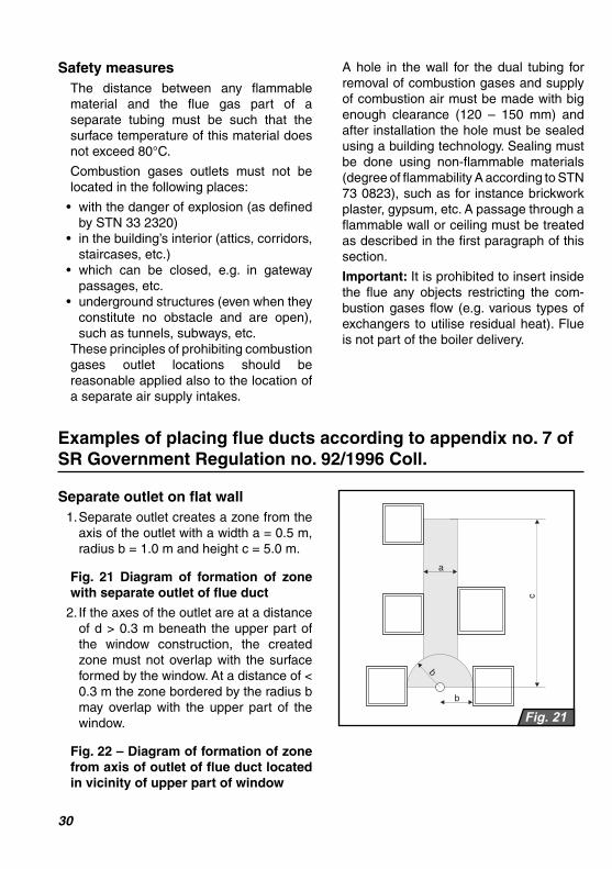
Separate outlet on flat wall
1. Separate outlet creates a zone from the
axis of the outlet with a width a = 0.5 m, radius b = 1.0 m and height c = 5.0 m.
Fig. 21 Diagram of formation of zone
with separate outlet of fl ue duct
2. If the axes of the outlet are at a distance
of d > 0.3 m beneath the upper part of the window construction, the created zone must not overlap with the surface
formed by the window. At a distance of <
0.3 m the zone bordered by the radius b may overlap with the upper part of the window.
Fig. 22 – Diagram of formation of zone from axis of outlet of fl ue duct located in vicinity of upper part of window
Fig. 21
Examples of placing fl ue ducts according to appendix no. 7 of SR Government Regulation no. 92/1996 Coll.
Safety measures
The distance between any fl ammable material and the fl ue gas part of a separate tubing must be such that the surface temperature of this material does not exceed 80°C.
Combustion gases outlets must not be located in the following places:
• with the danger of explosion (as defi ned by STN 33 2320)
• in the building’s interior (attics, corridors, staircases, etc.)
• which can be closed, e.g. in gateway passages, etc.
• underground structures (even when they constitute no obstacle and are open), such as tunnels, subways, etc.
These principles of prohibiting combustion gases outlet locations should be reasonable applied also to the location of a separate air supply intakes.
A hole in the wall for the dual tubing for removal of combustion gases and supply of combustion air must be made with big enough clearance (120 – 150 mm) and after installation the hole must be sealed using a building technology. Sealing must be done using non-fl ammable materials (degree of fl ammability A according to STN 73 0823), such as for instance brickwork plaster, gypsum, etc. A passage through a fl ammable wall or ceiling must be treated as described in the fi rst paragraph of this section.
Important: It is prohibited to insert inside the fl ue any objects restricting the com-bustion gases fl ow (e.g. various types of exchangers to utilise residual heat). Flue is not part of the boiler delivery.

31
Fig. 24
Fig. 23
Fig. 22
Dual outlet with horizontal arrangement on flat outside wall
The distances of the dual outlet on a fl at wall with horizontal arrangement are:
a = 1.5 m; g = 5.0 m; c = 5.0 m
In the case that g < 5 m, the zones are penetrated, in which it is necessary to adhere to a total zone width of 8 m, and proportionally increase the “a” values on both sides (e.g. g = 4.0 m then a = 2.0 m).
Fig. 23 – Dual outlet with horizontal arrangement on fl at outside wall
Dual outlet with vertical arrangement
The smallest distances in the case of a dual outlet with vertical arrangement on a fl at outside wall are:
a = 0.5 m; b = 1.0 m, c = 5.0 m, a1 depen-ding on x as follows
x > 5.0 m is a1 = 0.5 m
x > 4.0 m is a1 = 0.6 m
x > 3.0 m is a1 = 0.75 m
x > 2.0 m is a1 = 1.0 mx > 1.0 m is a1 = 1.2 m
Fig. 24 – Dual outlet with vertical arran-gement on fl at outside wallImportant notice!
Very important – read carefully!
The shown examples of locating fl ues may be used only when repairing or recon-structing buildings.
In all other cases it is necessary to pro-ceed in accordance with Public Notice No. 410/2003 of the Slovak Ministry of Environ-ment which amends ME Public Notice No. 706/2002 on sources of air pollution, on emission limits, on technical requirements and general operating conditions, on a list of pollutants, on classifi cation of sources of air pollution and on requirements for dispersion of polluting emissions.

32
Specifi cation of concentric Ø 60/100 fl ue components
K1M Elbow Ø 60 / 100 mm - 90° Item No.: 7738
Description: An elbow for changing the Ø 60/100 mm concentric air supply/fl ue tube route direction by 90°Please note: When connecting two elbows in a sequence without a 0.5 m stabilisation section, 1.5 Em pressure loss must be allowed for each elbow.Subassembly parts:1 × 90° elbow1 × Ø 60 mm sealing ring1 × Ø 100 mm sealing ring
Pressure loss: 1.0 Em
R1M Vertical adapter Ø 60 / 100 mm Item No.:7740
Description: Vertical adapter with combustion gases measuring points, designed for direct connection to the boiler’s Ø 60/100 mm concentric neckPlease note: You must start with this componentSubassembly parts:1 × adapter1 × Ø 60 mm sealing ring1 × Ø 100 mm sealing ringLength: 145 mmPressure loss: 0.2 Em
S1M Horizontal subassembly Ø 60 / 100 mm Item No.: 7739
Description: The subassembly is designed for direct connection to the boiler and horizontal outlet to the
façade. The outlet can run to the side or the back of the boiler. To achieve the required length of the route,
it is possible to incorporate more fl ue components: “T1M” tube and “K1M” elbow.
Subassembly parts:1 × 90° elbow
1 × Ø 60 mm sealing ring1 × Ø 60 mm air supply tube
1 × Ø 100 mm sealing ring1 × Ø 100 mm fl ue tube
1 × Ø 100 mm distance ring2 × Ø 100 mm cover sleeve
1 × sealing fl ange + fastenersSubassembly length 1 m / Pressure loss: 2 Em

33
T1M Concentric tube Ø 60 / 100 mm Item No.: 7737
Description: A 1 m long tube for extending horizontal
or vertical section of a Ø 60/100 mm diameter
concentric supply/fl ue tube routes. If it is necessary to
shorten the tube, saw off the end without a neck
Subassembly parts:
1 × Ø 60 mm air supply tube
1 × Ø 100 mm fl ue tube
1 × Ø 60 mm sealing ring
1 × Ø 100 mm sealing ring
Pressure loss: 1 Em
Description: Vertical adapter with combustion gases
measuring points, designed for direct connection to
the boiler’s Ø 60/100 mm concentric neck
Please note: You must start with this component
Subassembly parts:
1 × Ø 60/100 – Ø 80/125 mm adapter
1 × Ø 80 mm sealing ring
1 × Ø 125 mm sealing ring
Length: 142 mm
Pressure loss: 0.2 Em
Specifi cation of concentric Ø 80/125 fl ue components
R21M Vertical adapter Ø 80 / 125 mm Item No.: 7741
Description: 0.5 m long tube for extending horizontal or vertical section of concentric Ø 80/125 mm supply and flue tubing. If it is necessary to shorten the tube, saw off the end without a neckSubassembly parts:1 × Ø 80 mm supply tube1 × Ø 125 mm flue tube1 × Ø 80 mm sealing ring1 × Ø 125 mm sealing ring
Pressure loss: 0.5 Em
T21M-500 Concentric tube Ø 80 / 125 mm - 0,5 m Item No.: 7743

34
T21M-1000 Concentric tube Ø 80 / 125 mm - 1 m Item No.: 7743
Description: 1 m long tube for extending horizontal or vertical section of concentric Ø 80/125 mm supply and flue tubing. If it is necessary to shorten the tube, saw off the end without a neckSubassembly parts:1 × Ø 80 mm supply tube1 × Ø 125 mm flue tube1 × Ø 80 mm sealing ring1 × Ø 125 mm sealing ring
Pressure loss: 1 Em
Description: 0.4 - 0.5 m sliding tube for extending horizontal or vertical section of concentric Ø 80/125 mm supply and flue tubing. If it is necessary to shor-ten the tube, saw off the end without a neckSubassembly parts:1 × Ø 80 mm supply tube1 × Ø 125 mm flue tube1 × Ø 80 mm sealing ring1 × Ø 125 mm sealing ring
Pressure loss: 0.3 Em
T21MP Concentric tube sliding Ø 80 / 125 mm Item No.: 7742
Description: An elbow for changing the Ø 80/125 mm concentric air supply/flue tube route direction by 45°Please note: When connecting two elbows in a sequence without a 0.5 m stabilisation section, 1 Em pressure loss must be allowed for each elbow.Subassembly parts:1 × 45° elbow1 × Ø 80 mm sealing ring1 × Ø 125 mm sealing ring
Pressure loss: 0.5 E
K211M Elbow 45° - Ø 80 / 125 mm Item No.: 7745

35
K21M Elbow 90° - Ø 80 / 125 mm Item No.: 7746
Description: An elbow for changing the Ø 80/125 mm concentric air supply/flue tube route direction by 90°Please note: When connecting two elbows in a sequen-ce without a 0.5 m stabilisation section, 1,5 Em pressu-re loss must be allowed for each elbow.Subassembly parts:1 × 90° elbow1 × Ø 80 mm sealing ring1 × Ø 125 mm sealing ring
Pressure loss: 1 E
Description: The subassembly is designed for vertical
termination (on roof) of an Ø 80/125 mm concentric air
supply/fl ue tube route. For passage through the roof,
use the roof tile manufacturer’s roof passage transition
piece. The subassembly must be complemented with
an RM12M adapter for sealing the outside intake
tube.
Subassembly’s content:
1 × exhaust tube Ø 80 mm
1 × intake tube Ø 125 mm
Overall length: 1.2 m
Pressure loss: 1.5 Em
S21M Chimney subassembly Ø 80/125 mm Item No.: 7747
Description: A roof passage flushing piece with continuous-ly adjustable pitch angle (25 - 45°) and a shaped lead pipe grip. The piece is designed for sealing a transition between the S21M chimney subassembly and the roof tile.Subassembly parts:1 × roof passage transition piece (25° – 45°)
PS4 Roof bushing piece 25° - 45° Item No.: 7754

36
Description: A splitting adapter with combustion
gases reading points, designed for direct
connection to the boiler outlet, used to separate
the combustion gases (inside) and air (outside)
section of the Ø 60/100 mm concentric tubing
to two separate tubes of mutually independent
Ø 80 mm routes, one for combustion gases and
the other for combustion air.
Subassembly parts:
1 × splitting adapter with reading points
1 × splitting adapter support
1 × sealing ring for the boiler air section
2 × Ø 80 mm sealing ring
Specifi cation of separate Ø 80/80 fl ue components
R2M Splitting adapter 2 × Ø 80 Item No.: 7748
Description: 1m long tube for extending horizontal
or vertical section of a separate Ø 80 mm supply
and fl ue tube
Subassembly parts:
1 × separate tube
1 × Ø 80 mm sealing ring
Pressure loss: 1 Em
T2M Separate tube Ø 80 mm Item No.: 7750
U21 Pipe bracket Ø 80 / 125 mm Item No.: 7755
Description: A bracket for attaching a Ø 80/125 mm tu-be to a wall.Subassembly parts:3 × Ø 125 mm pipe bracket

37
Description: A set of tube end pieces designed for
connection to two mutually independent Ø 80 mm
tube routes (fl ue and supply ones). It is suitable for a
façade outlet, and can be combined with tubes “T2M”
or elbows “K2M” and “K12M”.
Subassembly parts:
2 × separate Ø 80 mm tube
2 × Ø 80 mm sealing ring
2 × Ø 80 mm internal sleeve
2 × Ø 80 mm external sleeve
Pressure loss: 1 Em (per tube)
S2M Separate tubes Ø 80 mm with cages Item No.: 7753
K12M Elbow Ø 80mm - 45° Item No.: 7752
Description: An elbow for changing the Ø 80 mm
separate supply or fl ue tube route direction by 45°
Please note: When connecting two elbows in a sequence,
1.0 Em pressure loss must be allowed for each elbow.
It is therefore recommended to install 0.5 straight tube
section between two elbows to stabilise fl ow.
Subassembly parts:
1 × 45° elbow
1 × Ø 80 mm sealing ring
Pressure loss: 0.5 Em
Description: An elbow for changing the Ø 80 mm
separate supply or fl ue tube route direction by 45°
Please note: When connecting two elbows in a sequence,
1.5 Em pressure loss must be allowed for each elbow.
It is therefore recommended to install 0.5 straight tube
section between two elbows to stabilise fl ow.
Subassembly parts:
1 × 45° elbow
1 × Ø 80 mm sealing ring
Pressure loss: 1 Em
K2M Elbow Ø 80mm - 90° Item No.: 7751
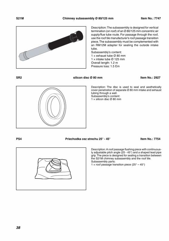
38
Description: The subassembly is designed for vertical
termination (on roof) of an Ø 80/125 mm concentric air
supply/fl ue tube route. For passage through the roof,
use the roof tile manufacturer’s roof passage transition
piece. The subassembly must be complemented with
an RM12M adapter for sealing the outside intake
tube.
Subassembly’s content:
1 × exhaust tube Ø 80 mm
1 × intake tube Ø 125 mm
Overall length: 1.2 m
Pressure loss: 1.5 Em
S21M Chimney subassembly Ø 80/125 mm Item No.: 7747
SR2 silicon disc Ø 80 mm Item No.: 2927
Description: The disc is used to seal and aesthetically cover penetration of separate Ø 80 mm intake and exhaust tubing through a wall.Subassembly’s content: 1 × silicon disc Ø 80 mm
Description: A roof passage flushing piece with continuous-ly adjustable pitch angle (25 - 45°) and a shaped lead pipe grip. The piece is designed for sealing a transition between the S21M chimney subassembly and the roof tile.Subassembly parts:1 × roof passage transition piece (25° – 45°)
PS4 Priechodka cez strechu 25° - 45° Item No.: 7754

39
Important: The fl ue must be always sloping towards the boiler, with a minimum gradient 3%.
R12M Adapter Ø 80 mm to Ø 80 / 125 mm Item No.: 7749
Description: Adapter for transition from Ø 80 mm to
Ø 80/125 mm diameter “S21M” chimney subassembly
Subassembly parts:
1 × adapter
U2 Pipe bracket Ø 80 mm Item No.: 7756
Description: A bracket for attaching an Ø 80 mm tube to the wallSubassembly parts:3 × Ø 80 mm pipe bracket
Z2K Tube end cage Ø 80 mm Item No.: 300941
Description: Muzzle for insertion on the end of an Ø 80 mm diameter horizontal exhaust tube. The muz-zle is inserted on a smooth end of the tube (If required the tube is cut to size). Important: The muzzle is used on the intake tube only. Subassembly parts:1 x muzzle end piece Ø 80 mm1 x self-cutting screwPressure loss: 0.5 Em

40
Important: It is prohibited to insert inside the fl ue any objects restricting the combustion gases fl ow (e.g. various types of exchangers to utilise residual heat). Flue is not part of the boiler delivery.
The boiler is connected to power supply by a three-core fl exible cord without a plug. The fi xed socket through which the boiler
is connected to power mains must comply with the provisions of STN 33 2000-4-46. It must always have a protective contact (peg), reliably connected with a PE or PEN wire (yellow-and-green). The boiler must be always connected to the protection wire (earth) through its power cord and must be always installed in such a way that the
Elektrické pripojenie kotla
Fig. 25
Wiring room control unit
KOTEL
Room thermostatConfiguration with
external room control
unit with relay
switching.
Terminal box is factory
fitted with a jumper
which must be
removed before the
control unit is wired.
WATER TANK
Power cord with
plug. Power mains
(230V / 50Hz)
Configuration with eBUS
external room control unit
Terminals for wiring outdoor
temperature sensor.
Equithermal control is
possible only if a control
unit supporting eBUS
communication is installed.
Configuration with tank
NTC sensor (KKO only)
Configuration with bimetal tank
thermostat (KKO only)

41
socket and the plug are accessible. Using various adapters, extension cords etc., is not permitted.
Important: The plug and the socket as well as a room control unit, which is an interference with the boiler’s internal wiring, must be under all circumstance connected by a qualifi ed electrician only, as defi ned by Public Notice No. 50/1978. Likewise servicing of the boiler’s electrical part must be done by a person with the above qualifi cation only. Before carrying out any works on its electrical section, the boiler must be disconnected from power supply by pulling the power cord plug from the power socket!
The main boiler section is protected by a tubular fuse (T 2 A / 250 V), situated on the boiler’s control panel – see the schematic diagrams on page 42 - 43.
Only room control units with zero-potential output may be used in conjunction with the boiler, i.e. units which feed no foreign voltage to the boiler.
Maximum load on the control unit with relay switching is 24 V / 0.1 A
The room control unit must be connected to the boiler by a two-core cable. The recommended copper wire cross-section
is between 0.5 and 1.5 sq.mm.
The room control unit connection cable must not run in parallel with power wires or cables.
The terminal box for wiring a room control unit, which is factory-fi tted with a jumper, is situated on the back of the boiler control panel.
The Lion boiler can be installed with a room control unit supporting the so called eBUS communication. For this type of control we recommend to use only Protherm Thermolink B or Thermolink P units. Only then we will be able to guarantee optimal functioning of the boiler. The room control unit cable is wired to the boiler terminal box (Fig. 25). With these units you will be able to make use of the equithermal control function. All equithermal curve settings are done through the room control unit.
Please note: To enable this type of control, an outdoor temperature sensor must be installed. The outdoor sensor cable is wired to the boiler terminal box (Fig. 25). The outdoor temperature sensor must be situated on the building’s coldest wall (usually northern side).
Important: The outdoor sensor cable and room control unit cable must not be installed in parallel with power cables (230
V power supply or similar).
42
Coupling the boiler with a tank
The boiler can run hand-in-hand with an external PROTHERM tank (B 60 Z, B 100 MS, B 100 Z, B 200 Z, etc.).
For this connection you need to buy the water tank NTC sensor
The installation must be done by appropri-ately trained service technician.
Converting the boiler to an alternative fuel (propane)
The Protherm Lion 28 (24) KKV and 28 KKO boilers are as standard made to run on natural gas. If it is required that the boiler is run on propane, it has to be con-verted for this type of fuel.
Important: The conversion must be done by an authorised technician with valid manufacturer’s certifi cate.
The authorised technician who converts the boiler to an alternative type of fuel must also make all required relevant iden-
tifi cation and secure the boiler against
unauthorised interference.
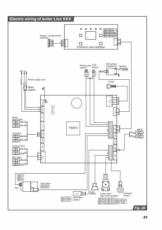
43
Electric wiring of boiler Lion KKV
Fig. 26
X90
X
32
X22
X
43
X51
X
21
X41
X
40
X91
X
19
X17
X
15
X10
X
12
X10
1
X2
X20
X
14
1 1
1 1
1 1
1 1
1 1
1 1
1 1
Mainswitch
Power supply cord
PE
N
N
L
L
PE
blue
gree
n/ye
llow
brow
n
1 2 3 4 5
7 8 9
10
6
11 12 13 14 15 16 17 18
1 2 3 4 5
7 8
9 10
6
11 12 13 14 15 16
1 1
2 2
1 1
2 2
blue
blue
red
red
Roomthermostat
Aquastat
X19.5
X19.2
X19.3
X19.4
blue
green
yellow
X40.3
X40.4
X40.2
X40.1
1 1
2 2
1 1
2 2
Outdoor NTC
NTC Tank
Pump
Ignitionelectrode
1
2
ZIG ignitiontransformer
GND
+Vall 4
3
GND
Testing - programminginterface
TRAFO
TOPsensor
blue
X2.
8
red
X2.
7
red
X2.
5
1 1
2 2
blue
white
X32.1
X32.2
eBUS
Fan
Gas valve
1
1 re X20.189 bl X20.9
1 X20.17 2 X20.3 4 X20.4 5 X20.16
1
black
Protherm user interface
1
1 X51.1 GND 2 X51.2 reset 4 X51.4 +5 VDC 5 X51.5 +24 VDC 6 X51.6 P-eBUS
HoW flowsensor
2 3
1
FUGAS
1 X2.2 GND 2 X2.6 signal 3 X2.3 +5V
3 3 4 4
1 1
Pressuresensor
1 X2.12 signal 3 X2.11 +5 V 4 X2.9 GND
Return pipesensor
3-way valvestep motor actuator
1 X2.16 3wv_SM_OUT_1 2 X2.8 3wv_SM_OUT_2 3 X2.15 3wv_SM_OUT_3 4 X2.7 3wv_SM_OUT_4
X2.
1
X2.
5
HoWsensor
blue
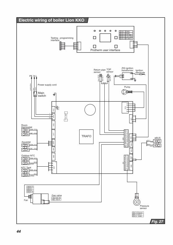
44
Electric wiring of boiler Lion KKO
Fig. 27
X90
X
32
X22
X
43
X51
X
21
X41
X
40
X91
X
19
X17
X
15
X10
X
12
X10
1
X2
X20
X
14
1 1
1 1
1 1
1 1
1 1
1 1
1 1
PE
N
N
L
L
PE
1 2 3 4 5
7 8 9
10
6
11 12 13 14 15 16 17 18
1 2 3 4 5
7 8
9 10
6
11 12 13 14 15 16
1 1
2 2
1 1
2 2
X19.5
X19.2
X19.3
X19.4
X40.3
X40.4
X40.2
X40.1
1 1
2 2
1 1
2 2
1
2 GND
+Vall 4
3
GND
TRAFO 1 1
2 2
X32.1
X32.2
eBUS
1
1 re X20.189 bl X20.9
1 X20.17 2 X20.3 4 X20.4 5 X20.16
1
Protherm user interface
1
1 X51.1 GND 2 X51.2 reset 4 X51.4 +5 VDC 5 X51.5 +24 VDC 6 X51.6 P-eBUS
3 3 4 4
1 1
1 X2.12 signal 3 X2.11 +5 V 4 X2.9 GND
Mainswitch
Power supply cord
blue
gree
n/ye
llow
brow
n
blue
blue
red
red
Roomthermostat
Aquastat
blue
green
yellow
Outdoor NTC
NTC Tank
Pump
Ignitionelectrode
ZIG ignitiontransformer
Testing - programminginterface
TOPsensor
blue
X2.
8
red
X2.
7
red
X2.
5
blue
white
Fan
Gas valve
black
Pressuresensor
Return pipesensor
blue