linworks - lipowsky · linworks quickstart folie-3 lin single wire hardware open collector output...
TRANSCRIPT

LINWorks QuickStart Folie-1
LINWorks
Quick-Start
LINWorks QuickStart Folie-2
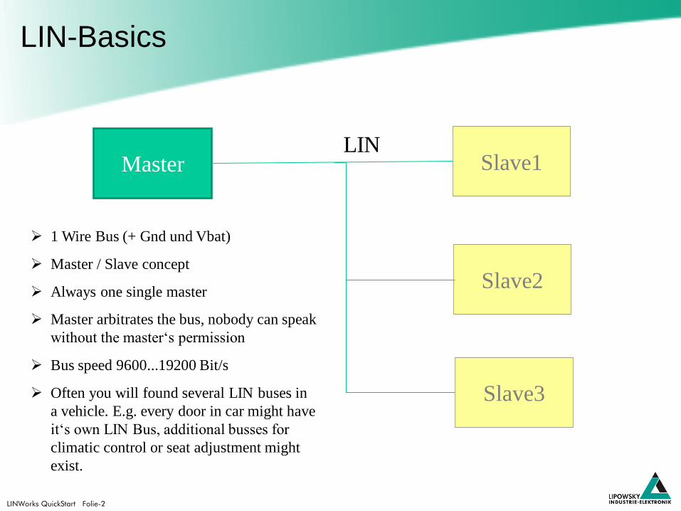
LIN-Basics
1 Wire Bus (+ Gnd und Vbat)
Master / Slave concept
Always one single master
Master arbitrates the bus, nobody can speak
without the master‘s permission
Bus speed 9600...19200 Bit/s
Often you will found several LIN buses in
a vehicle. E.g. every door in car might have
it‘s own LIN Bus, additional busses for
climatic control or seat adjustment might
exist.
Master Slave1
Slave2
Slave3
LIN
LINWorks QuickStart Folie-3
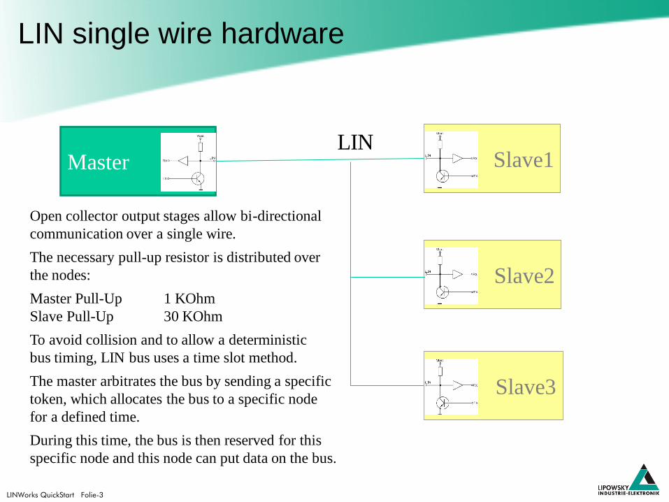
LIN single wire hardware
Open collector output stages allow bi-directional
communication over a single wire.
The necessary pull-up resistor is distributed over
the nodes:
Master Pull-Up 1 KOhm
Slave Pull-Up 30 KOhm
To avoid collision and to allow a deterministic
bus timing, LIN bus uses a time slot method.
The master arbitrates the bus by sending a specific
token, which allocates the bus to a specific node
for a defined time.
During this time, the bus is then reserved for this
specific node and this node can put data on the bus.
Master Slave1
Slave2
Slave3
LIN
LINWorks QuickStart Folie-4
LIN Data Transfer
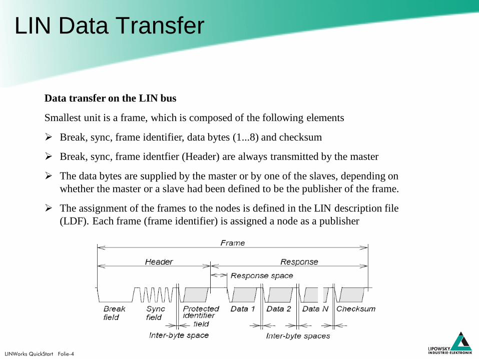
Data transfer on the LIN bus
Smallest unit is a frame, which is composed of the following elements
Break, sync, frame identifier, data bytes (1...8) and checksum
Break, sync, frame identfier (Header) are always transmitted by the master
The data bytes are supplied by the master or by one of the slaves, depending on
whether the master or a slave had been defined to be the publisher of the frame.
The assignment of the frames to the nodes is defined in the LIN description file
(LDF). Each frame (frame identifier) is assigned a node as a publisher
LINWorks QuickStart Folie-5
LIN Frame composition
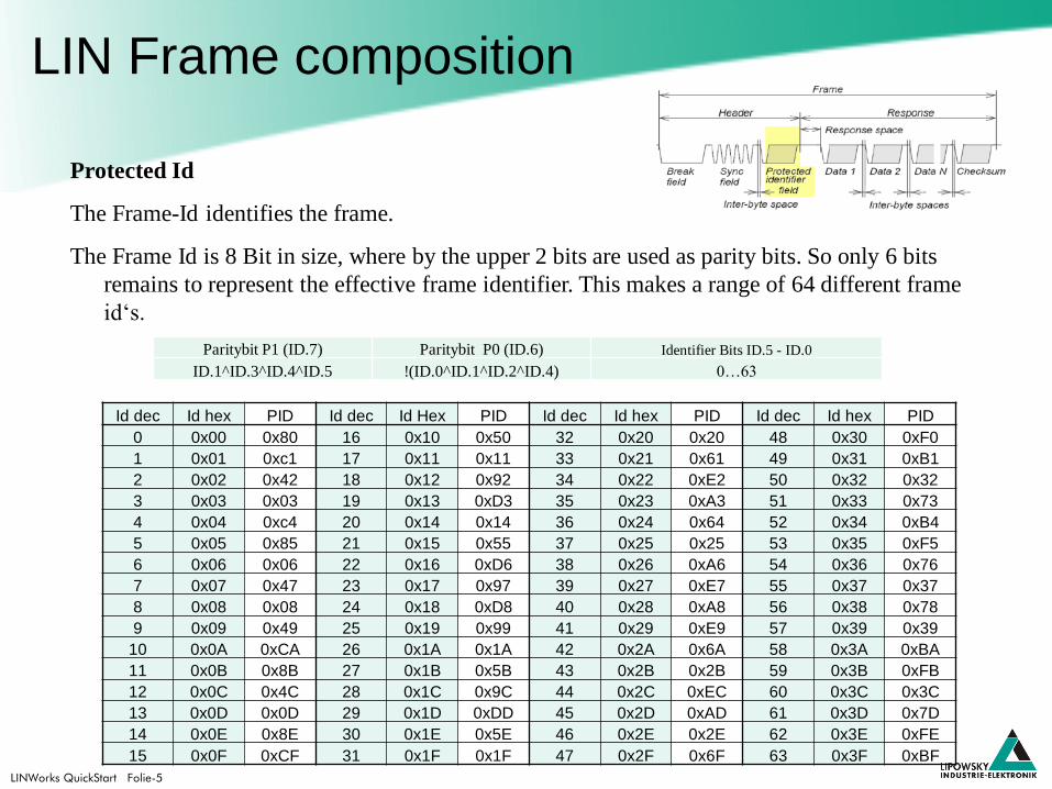
Protected Id
The Frame-Id identifies the frame.
The Frame Id is 8 Bit in size, where by the upper 2 bits are used as parity bits. So only 6 bits
remains to represent the effective frame identifier. This makes a range of 64 different frame
id‘s.
Paritybit P1 (ID.7) Paritybit P0 (ID.6) Identifier Bits ID.5 - ID.0
ID.1^ID.3^ID.4^ID.5 !(ID.0^ID.1^ID.2^ID.4) 0…63
Id dec Id hex PID Id dec Id Hex PID Id dec Id hex PID Id dec Id hex PID
0 0x00 0x80 16 0x10 0x50 32 0x20 0x20 48 0x30 0xF0
1 0x01 0xc1 17 0x11 0x11 33 0x21 0x61 49 0x31 0xB1
2 0x02 0x42 18 0x12 0x92 34 0x22 0xE2 50 0x32 0x32
3 0x03 0x03 19 0x13 0xD3 35 0x23 0xA3 51 0x33 0x73
4 0x04 0xc4 20 0x14 0x14 36 0x24 0x64 52 0x34 0xB4
5 0x05 0x85 21 0x15 0x55 37 0x25 0x25 53 0x35 0xF5
6 0x06 0x06 22 0x16 0xD6 38 0x26 0xA6 54 0x36 0x76
7 0x07 0x47 23 0x17 0x97 39 0x27 0xE7 55 0x37 0x37
8 0x08 0x08 24 0x18 0xD8 40 0x28 0xA8 56 0x38 0x78
9 0x09 0x49 25 0x19 0x99 41 0x29 0xE9 57 0x39 0x39
10 0x0A 0xCA 26 0x1A 0x1A 42 0x2A 0x6A 58 0x3A 0xBA
11 0x0B 0x8B 27 0x1B 0x5B 43 0x2B 0x2B 59 0x3B 0xFB
12 0x0C 0x4C 28 0x1C 0x9C 44 0x2C 0xEC 60 0x3C 0x3C
13 0x0D 0x0D 29 0x1D 0xDD 45 0x2D 0xAD 61 0x3D 0x7D
14 0x0E 0x8E 30 0x1E 0x5E 46 0x2E 0x2E 62 0x3E 0xFE
15 0x0F 0xCF 31 0x1F 0x1F 47 0x2F 0x6F 63 0x3F 0xBF
LINWorks QuickStart Folie-6
LIN description file
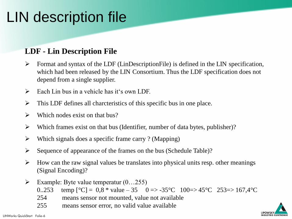
LDF - Lin Description File
Format and syntax of the LDF (LinDescriptionFile) is defined in the LIN specification,
which had been released by the LIN Consortium. Thus the LDF specification does not
depend from a single supplier.
Each Lin bus in a vehicle has it‘s own LDF.
This LDF defines all charcteristics of this specific bus in one place.
Which nodes exist on that bus?
Which frames exist on that bus (Identifier, number of data bytes, publisher)?
Which signals does a specific frame carry ? (Mapping)
Sequence of appearance of the frames on the bus (Schedule Table)?
How can the raw signal values be translates into physical units resp. other meanings
(Signal Encoding)?
Example: Byte value temperatur (0…255)
0..253 temp [°C] = 0,8 * value – 35 0 => -35°C 100=> 45°C 253=> 167,4°C
254 means sensor not mounted, value not available
255 means sensor error, no valid value available
LINWorks QuickStart Folie-7
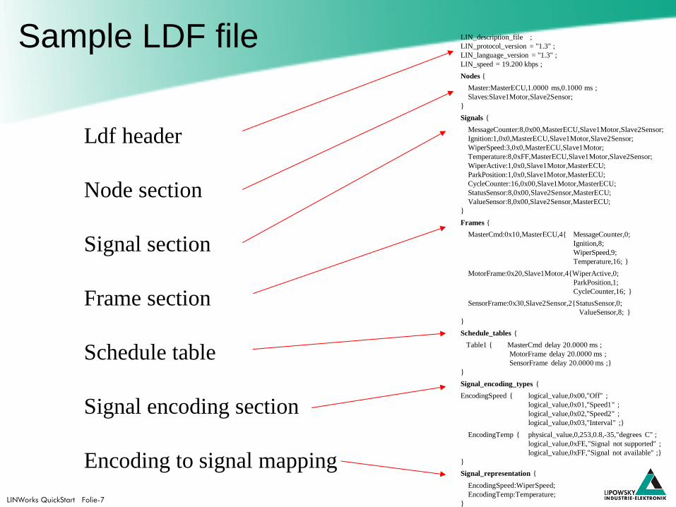
Sample LDF file
Ldf header
Node section
Signal section
Frame section
Schedule table
Signal encoding section
Encoding to signal mapping
LIN_description_file ;
LIN_protocol_version = "1.3" ;
LIN_language_version = "1.3" ;
LIN_speed = 19.200 kbps ;
Nodes {
Master:MasterECU,1.0000 ms,0.1000 ms ;
Slaves:Slave1Motor,Slave2Sensor;
}
Signals {
MessageCounter:8,0x00,MasterECU,Slave1Motor,Slave2Sensor;
Ignition:1,0x0,MasterECU,Slave1Motor,Slave2Sensor;
WiperSpeed:3,0x0,MasterECU,Slave1Motor;
Temperature:8,0xFF,MasterECU,Slave1Motor,Slave2Sensor;
WiperActive:1,0x0,Slave1Motor,MasterECU;
ParkPosition:1,0x0,Slave1Motor,MasterECU;
CycleCounter:16,0x00,Slave1Motor,MasterECU;
StatusSensor:8,0x00,Slave2Sensor,MasterECU;
ValueSensor:8,0x00,Slave2Sensor,MasterECU;
}
Frames {
MasterCmd:0x10,MasterECU,4{ MessageCounter,0;
Ignition,8;
WiperSpeed,9;
Temperature,16; }
MotorFrame:0x20,Slave1Motor,4{WiperActive,0;
ParkPosition,1;
CycleCounter,16; }
SensorFrame:0x30,Slave2Sensor,2{StatusSensor,0;
ValueSensor,8; }
}
Schedule_tables {
Table1 { MasterCmd delay 20.0000 ms ;
MotorFrame delay 20.0000 ms ;
SensorFrame delay 20.0000 ms ;}
}
Signal_encoding_types {
EncodingSpeed { logical_value,0x00,"Off" ;
logical_value,0x01,"Speed1" ;
logical_value,0x02,"Speed2" ;
logical_value,0x03,"Interval" ;}
EncodingTemp { physical_value,0,253,0.8,-35,"degrees C" ;
logical_value,0xFE,"Signal not supported" ;
logical_value,0xFF,"Signal not available" ;}
}
Signal_representation {
EncodingSpeed:WiperSpeed;
EncodingTemp:Temperature;
}
LINWorks QuickStart Folie-8
LIN application frames
Break Sync Identifier Databyte1 Databyte2 CheckSum
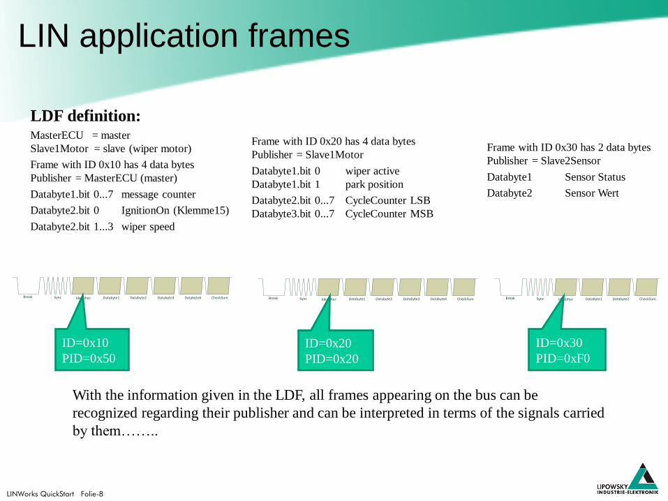
LDF definition: MasterECU = master
Slave1Motor = slave (wiper motor)
Frame with ID 0x10 has 4 data bytes
Publisher = MasterECU (master)
Databyte1.bit 0...7 message counter
Databyte2.bit 0 IgnitionOn (Klemme15)
Databyte2.bit 1...3 wiper speed
Frame with ID 0x20 has 4 data bytes
Publisher = Slave1Motor
Databyte1.bit 0 wiper active
Databyte1.bit 1 park position
Databyte2.bit 0...7 CycleCounter LSB
Databyte3.bit 0...7 CycleCounter MSB
With the information given in the LDF, all frames appearing on the bus can be
recognized regarding their publisher and can be interpreted in terms of the signals carried
by them……..
Break Sync Identifier Databyte1 Databyte2 CheckSumDatabyte3 Databyte4 Break Sync Identifier Databyte1 Databyte2 CheckSumDatabyte3 Databyte4
Frame with ID 0x30 has 2 data bytes
Publisher = Slave2Sensor
Databyte1 Sensor Status
Databyte2 Sensor Wert
ID=0x30
PID=0xF0
ID=0x10
PID=0x50
ID=0x20
PID=0x20

LINWorks QuickStart Folie-9
LIN application frames
Break Sync Identifier Databyte1 Databyte2 CheckSum
LDF definition: MasterECU = Master
Slave1Motor = Slave (Wiper motor)
Frame with ID 0x10 has 4 data bytes
Publisher = MasterECU (Master)
Databyte1.bit 0...7 message counter
Databyte2.bit 0 IgnitionOn (Klemme15)
Databyte2.bit 1...3 wiper speed
Frame with ID 0x20 has 4 data bytes
Publisher = Slave1Motor
Databyte1.bit 0 wiper active
Databyte1.bit 1 park position
Databyte2.bit 0...7 CycleCounter LSB
Databyte3.bit 0...7 CycleCounter MSB
Break Sync Identifier Databyte1 Databyte2 CheckSumDatabyte3 Databyte4 Break Sync Identifier Databyte1 Databyte2 CheckSumDatabyte3 Databyte4
Frame mit ID 0x30 has 2 data bytes
Publisher = Slave2Sensor
Databyte1 StatusSensor
Databyte2 ValueSensor
With the information given in the LDF, all frames appearing on the bus can be recognized
regarding their publisher and can be interpreted in terms of the signals carried by
them……..
Nearly all frames, because there are some special frames…..
ID=0x30
PID=0xF0
ID=0x10
PID=0x50
ID=0x20
PID=0x20

LINWorks QuickStart Folie-10
LIN diagnostic frames 0x3c/0x3d
0x3C MasterRequest: Request data
published by the master, defines the node
and the action, which should be carried out.
0x3D SlaveResponse: Response data of the
slave node, which had been addressed by the
previous master request.
Specific characteristics of Master Request and Slave Response frames
•These frames always have 8 data bytes and they always use the classic checksum.
•The content of these frame is not fixed, dependent of the content of the master frame, a
specific slave node will answer. The content of the answer also depends on the data in the
MasterRequest frame.
•Request and Response data can be composed of more than 8 bytes. In this case the
diagnostic transport layer (Cooked Mode) is used to transfer the data by multiple frames.
Break Sync Identifier Databyte1 Databyte2 Databyte3 Databyte4 Databyte5 Databyte6 Databyte7 Databyte8 CheckSum
ID=0x3c
MasterRequest
ID=0x3D
SlaveResponse

LINWorks QuickStart Folie-11
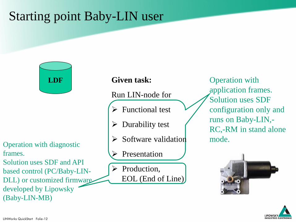
Starting point Baby-LIN user
LDF Given task:
Run LIN-node for
Functional test
Durability test
Software validation
Presentation
Production,
EOL (End of Line)
LINWorks QuickStart Folie-12
LDF Operation with
application frames.
Solution uses SDF
configuration only and
runs on Baby-LIN,-
RC,-RM in stand alone
mode. Operation with diagnostic
frames.
Solution uses SDF and API
based control (PC/Baby-LIN-
DLL) or customized firmware
developed by Lipowsky
(Baby-LIN-MB)
Given task:
Run LIN-node for
Functional test
Durability test
Software validation
Presentation
Production,
EOL (End of Line)
Starting point Baby-LIN user
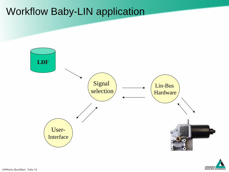
LINWorks QuickStart Folie-13
Workflow Baby-LIN application
LDF
Lin-Bus
Hardware
Signal
selection
User- Interface
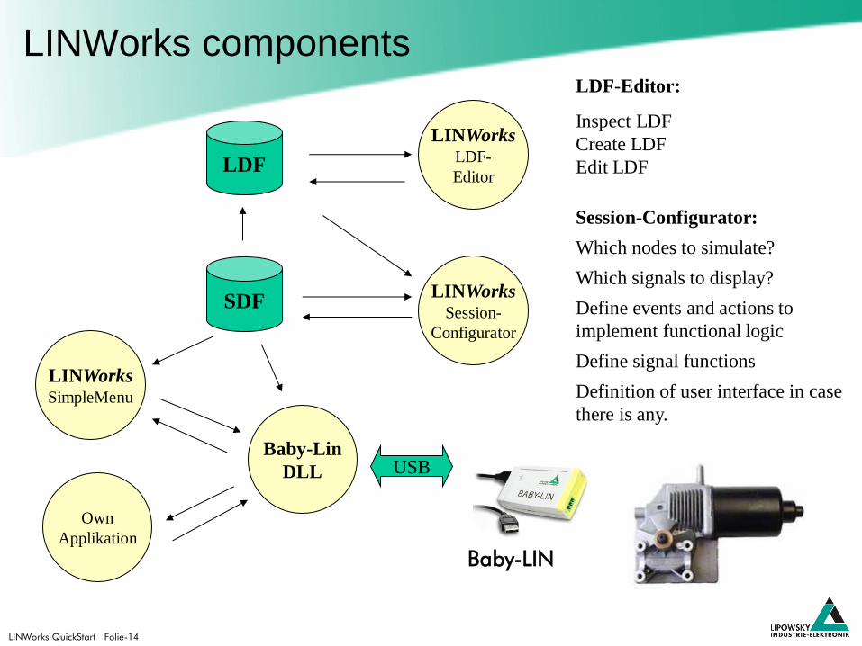
LINWorks QuickStart Folie-14
LINWorks components LDF-Editor:
Inspect LDF
Create LDF
Edit LDF
Session-Configurator:
Which nodes to simulate?
Which signals to display?
Define events and actions to
implement functional logic
Define signal functions
Definition of user interface in case
there is any.
LDF
LINWorks LDF-
Editor
LINWorks Session-
Configurator
Baby-Lin
DLL
LINWorks SimpleMenu
Own
Applikation
SDF
USB
Baby-LIN
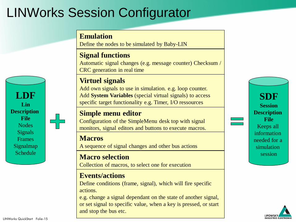
LINWorks QuickStart Folie-15
LINWorks Session Configurator
LDF Lin
Description
File
Nodes
Signals
Frames
Signalmap
Schedule
SDF Session
Description
File
Keeps all
information
needed for a
simulation
session
Emulation Define the nodes to be simulated by Baby-LIN
Macros A sequence of signal changes and other bus actions
Signal functions Automatic signal changes (e.g. message counter) Checksum /
CRC generation in real time
Simple menu editor Configuration of the SimpleMenu desk top with signal
monitors, signal editors and buttons to execute macros.
Events/actions Define conditions (frame, signal), which will fire specific
actions.
e.g. change a signal dependant on the state of another signal,
or set signal to specific value, when a key is pressed, or start
and stop the bus etc.
Virtuel signals Add own signals to use in simulation. e.g. loop counter.
Add System Variables (special virtual signals) to access
specific target functionality e.g. Timer, I/O ressources
Macro selection Collection of macros, to select one for execution

LINWorks QuickStart Folie-16
LINWorks SessionConf
Minimal Setup:
Import LDF file to Session Configurator
Define Emulation Setup
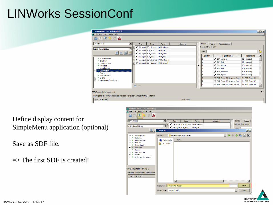
LINWorks QuickStart Folie-17
LINWorks SessionConf
Define display content for
SimpleMenu application (optional)
Save as SDF file.
=> The first SDF is created!
LINWorks QuickStart Folie-18
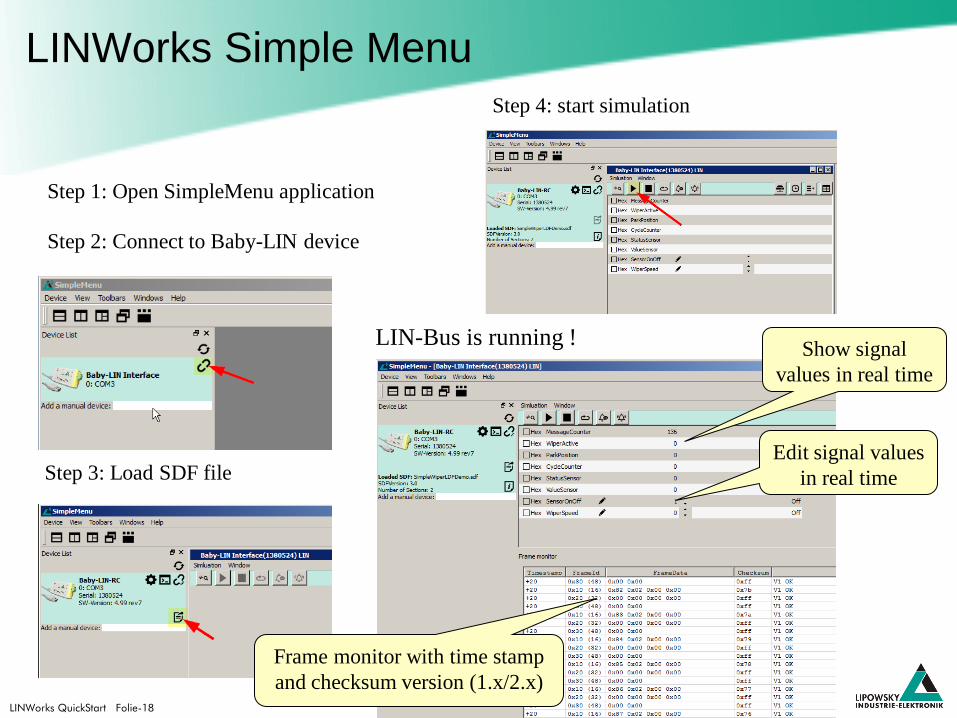
LINWorks Simple Menu
Step 1: Open SimpleMenu application
Step 2: Connect to Baby-LIN device
Step 4: start simulation
LIN-Bus is running ! Show signal
values in real time
Edit signal values
in real time
Frame monitor with time stamp
and checksum version (1.x/2.x)
Step 3: Load SDF file

LINWorks QuickStart Folie-19
LINWorks Simple Menu
Start, Stop, Wakeup und Sleep
command.
Restart command allows to start the
Bus without resetting the signals to
their default values from the SDF.
This happens when the Start
command is used.
Select or deselect
nodes for simulation
dynamically
Configure signal monitors and
signal editors, macro and macro
selections.
This can be done additional to the
definitions given in the SDF.

LINWorks QuickStart Folie-20
LINWorks details
Evaluation of all sections in the
LINWorks SessionConfigurator.
As a starting point we are
using the SimpleWiper.SDF
Everybody is invited to perform
all the presented steps on the
own computer.
LINWorks QuickStart Folie-21
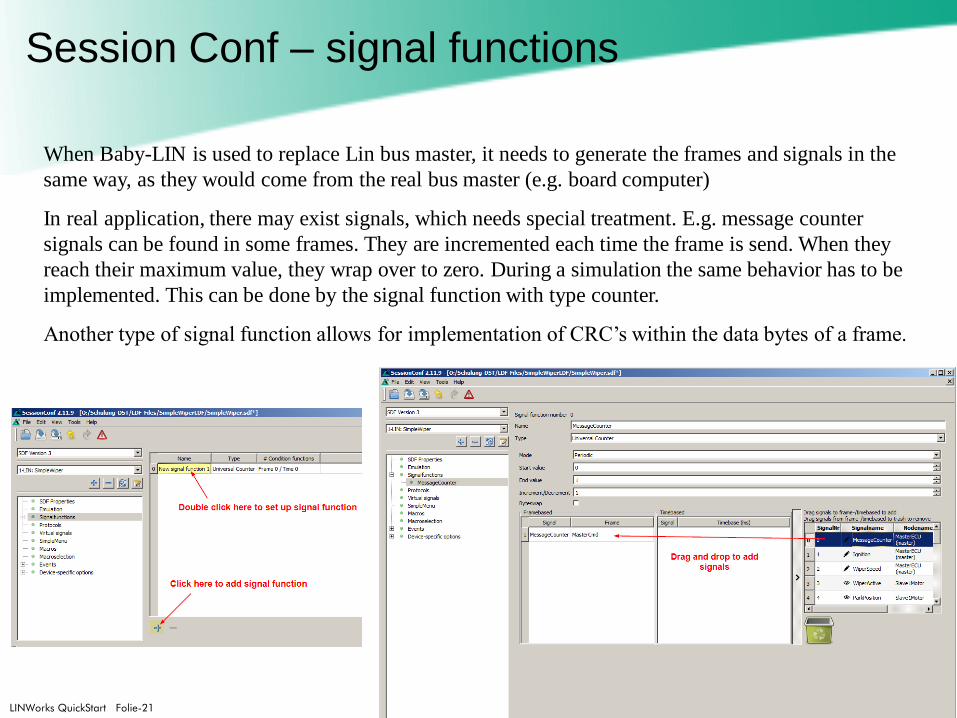
Session Conf – signal functions
When Baby-LIN is used to replace Lin bus master, it needs to generate the frames and signals in the
same way, as they would come from the real bus master (e.g. board computer)
In real application, there may exist signals, which needs special treatment. E.g. message counter
signals can be found in some frames. They are incremented each time the frame is send. When they
reach their maximum value, they wrap over to zero. During a simulation the same behavior has to be
implemented. This can be done by the signal function with type counter.
Another type of signal function allows for implementation of CRC’s within the data bytes of a frame.
LINWorks QuickStart Folie-22
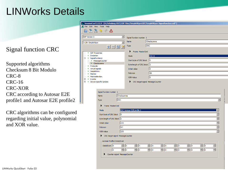
LINWorks Details
Signal function CRC
Supported algorithms
Checksum 8 Bit Modulo
CRC-8
CRC-16
CRC-XOR
CRC according to Autosar E2E
profile1 and Autosar E2E profile2
CRC algorithms can be configured
regarding initial value, polynomial
and XOR value.

LINWorks QuickStart Folie-23
Session Conf – virtual signals
Virtual signals section allows to define own signals additional to the signals available in the
LDF file. These signals will not appear on the bus, but can be used in macros, events etc.
Use case: implementation of a cycle counter by using the bus signal park position. Each time
the bus signal park position toggles, the virtual signal AuxCycleCounter will be incremented.

LINWorks QuickStart Folie-24
SessionConf – System variables
System variables => special virtual signals
There exist virtual signals with reserved names.
If these signals are used, a virtual signal is created and
additional this virtual signal is connected to a specific
system resource like timers, input and output signals
and other kind of system configuration items.
The available system variables will vary dependent on the specific hardware type.
All system variable names will start with the Prefix @@SYS.
Some timer related system variables:
@@SYSTIMER_UP defines an Up-Counter, which counts up when its value is unequal 0.
The counting tick is one second.
@@SYSTTIMER_DOWN defines a Down-Counter, which counts until it’s value equals 0.
The counting tick is one second.
@@SYSTIMER_FAST_UP same as SYSTIMER_UP, but counting tick is 10 ms.
@@SYSTIMER_FAST_DOWN same as SYSTIMER_DOWN, but counting tick is 10
ms.
.

LINWorks QuickStart Folie-25
SessionConf – System variables
More @@SYSxxx system variables for I/O control
@@SYSDIGIN1…x Access to input states of digital inputs of Baby-LIN-RM-II
@@SYSDIGOUT1…x Control of the digital outputs of the Baby-LIN-RM-II
@@SYSPWMOUT1…4 Generation of up to 4 PWM outputs signals. The signal value [0…100%]
defines the pulse/pause ratio of the PWM output.
@@SYSPWMPERIOD This system variable defines the base frequency of the PWM output.
The frequency can be setup in the range of 1 to 500 Hz.
@@SYSPWMIN1..2 The both inputs DIN7 (@@SYSPWMIN1) and DIN8 (@@SYSPWMIN2)
can be decoded as PWM inputs.
@@SYSPWMINFULLSCALE This system variable defines the full scale value (= 100 % value)
Per default this value is set to 200.
The @@SYSDIGIN1…x and the @@SYSPWMIN1..2 system variables can be used in a signal
ONCHANGE event, to transfer the state of an digital input into a LIN bus signal.

LINWorks QuickStart Folie-26
Session Conf - Macros
Macros are used to combine multiple operations (macro commands) in a sequence.
Macros can be executed as an event action, or via an API call, when using the Baby-LIN-DLL.
In SDF-V3 macros also can be called from within another macro in terms of a goto or a gosub.
LINWorks QuickStart Folie-27
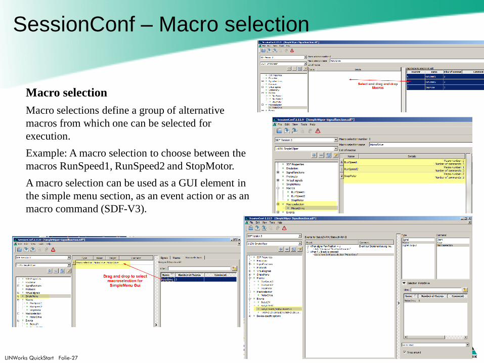
SessionConf – Macro selection
Macro selection
Macro selections define a group of alternative
macros from which one can be selected for
execution.
Example: A macro selection to choose between the
macros RunSpeed1, RunSpeed2 and StopMotor.
A macro selection can be used as a GUI element in
the simple menu section, as an event action or as an
macro command (SDF-V3).
LINWorks QuickStart Folie-28
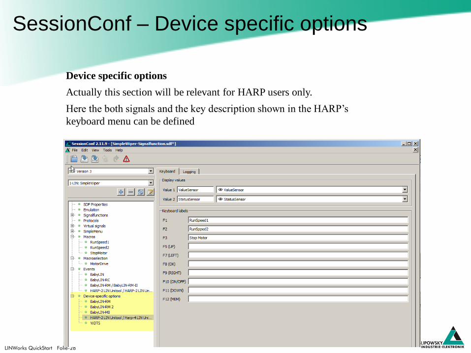
SessionConf – Device specific options
Device specific options
Actually this section will be relevant for HARP users only.
Here the both signals and the key description shown in the HARP’s
keyboard menu can be defined
LINWorks QuickStart Folie-29
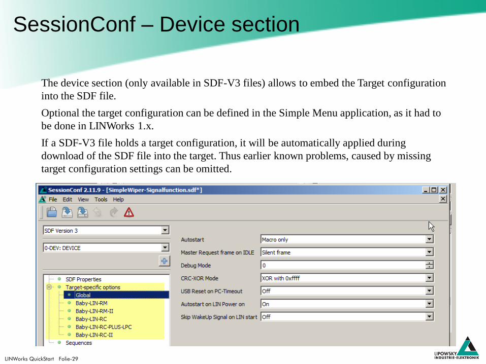
SessionConf – Device section
The device section (only available in SDF-V3 files) allows to embed the Target configuration
into the SDF file.
Optional the target configuration can be defined in the Simple Menu application, as it had to
be done in LINWorks 1.x.
If a SDF-V3 file holds a target configuration, it will be automatically applied during
download of the SDF file into the target. Thus earlier known problems, caused by missing
target configuration settings can be omitted.