linux port to latticemico32 system quick-start guide
TRANSCRIPT
Linux Port toLatticeMico32 System
Quick-Start Guide
Lattice Semiconductor Corporation5555 NE Moore CourtHillsboro, OR 97124(503) 268-8000
February 2008
Linux Port to LatticeMico32 System Quick-Start Guide ii
CopyrightCopyright © 2008 Lattice Semiconductor Corporation.
This document may not, in whole or part, be copied, photocopied, reproduced, translated, or reduced to any electronic medium or machine-readable form without prior written consent from Lattice Semiconductor Corporation.
TrademarksLattice Semiconductor Corporation, L Lattice Semiconductor Corporation (logo), L (stylized), L (design), Lattice (design), LSC, E2CMOS, Extreme Performance, FlashBAK, flexiFlash, flexiMAC, flexiPCS, FreedomChip, GAL, GDX, Generic Array Logic, HDL Explorer, IPexpress, ISP, ispATE, ispClock, ispDOWNLOAD, ispGAL, ispGDS, ispGDX, ispGDXV, ispGDX2, ispGENERATOR, ispJTAG, ispLEVER, ispLeverCORE, ispLSI, ispMACH, ispPAC, ispTRACY, ispTURBO, ispVIRTUAL MACHINE, ispVM, ispXP, ispXPGA, ispXPLD, LatticeEC, LatticeECP, LatticeECP-DSP, LatticeECP2, LatticeECP2M, LatticeMico8, LatticeMico32, LatticeSC, LatticeSCM, LatticeXP, LatticeXP2, MACH, MachXO, MACO, ORCA, PAC, PAC-Designer, PAL, Performance Analyst, PURESPEED, Reveal, Silicon Forest, Speedlocked, Speed Locking, SuperBIG, SuperCOOL, SuperFAST, SuperWIDE, sysCLOCK, sysCONFIG, sysDSP, sysHSI, sysI/O, sysMEM, The Simple Machine for Complex Design, TransFR, UltraMOS, and specific product designations are either registered trademarks or trademarks of Lattice Semiconductor Corporation or its subsidiaries in the United States and/or other countries. ISP, Bringing the Best Together, and More of the Best are service marks of Lattice Semiconductor Corporation.
HyperTransport is a licensed trademark of the HyperTransport Technology Consortium in the U.S. and other jurisdictions.
Other product names used in this publication are for identification purposes only and may be trademarks of their respective companies.
DisclaimersNO WARRANTIES: THE INFORMATION PROVIDED IN THIS DOCUMENT IS “AS IS” WITHOUT ANY EXPRESS OR IMPLIED WARRANTY OF ANY KIND INCLUDING WARRANTIES OF ACCURACY, COMPLETENESS, MERCHANTABILITY, NONINFRINGEMENT OF INTELLECTUAL PROPERTY, OR FITNESS FOR ANY PARTICULAR PURPOSE. IN NO EVENT WILL LATTICE SEMICONDUCTOR CORPORATION (LSC) OR ITS SUPPLIERS BE LIABLE FOR ANY DAMAGES WHATSOEVER (WHETHER DIRECT, INDIRECT, SPECIAL, INCIDENTAL, OR CONSEQUENTIAL, INCLUDING, WITHOUT LIMITATION, DAMAGES FOR LOSS OF PROFITS, BUSINESS INTERRUPTION, OR LOSS OF INFORMATION) ARISING OUT OF THE USE OF OR INABILITY TO USE THE INFORMATION PROVIDED IN THIS DOCUMENT, EVEN IF LSC HAS BEEN ADVISED OF THE POSSIBILITY OF SUCH DAMAGES. BECAUSE SOME JURISDICTIONS PROHIBIT THE EXCLUSION OR LIMITATION OF CERTAIN LIABILITY, SOME OF THE ABOVE LIMITATIONS MAY NOT APPLY TO YOU.
LSC may make changes to these materials, specifications, or information, or to the products described herein, at any time without notice. LSC makes no commitment to update this documentation. LSC reserves the right to discontinue any product or service without notice and assumes no obligation
Linux Port to LatticeMico32 System Quick-Start Guide iii
to correct any errors contained herein or to advise any user of this document of any correction if such be made. LSC recommends its customers obtain the latest version of the relevant information to establish, before ordering, that the information being relied upon is current.
Type Conventions Used in This Document
Convention Meaning or Use
Bold Items in the user interface that you select or click. Text that you type into the user interface.
<Italic> Variables in commands, code syntax, and path names.
Ctrl+L Press the two keys at the same time.
Courier Code examples. Messages, reports, and prompts from the software.
... Omitted material in a line of code.
.
.
.
Omitted lines in code and report examples.
[ ] Optional items in syntax descriptions. In bus specifications, the brackets are required.
( ) Grouped items in syntax descriptions.
{ } Repeatable items in syntax descriptions.
| A choice between items in syntax descriptions.

Linux Port to LatticeMico32 System Quick-Start Guide iv
Linux Port to LatticeMico32 System Quick-Start Guide v
Contents
Linux Port to LatticeMico32 System Quick-Start Guide 1Prerequisites 2
Lattice Semiconductor ispLEVER Tools 2TFTP Server 2ispVM System 2lm32-elf-gdb and TCP2JTAGVC2 2Remote Serial Console 3Binary Distribution Tarball 3
Setting Up the Build Environment 3Starting the LatticeMico32 System SDK Shell 3Unpacking the Distribution Tarball 4Tarball Contents 4Providing Required Files Through TFTP 5
Downloading the Bitstream to the FPGA 5Components and Memory Layout of the Bitstream 5Programming the Bitstream 6
Loading U-Boot 6Setting Up the Hardware 6Setting Up the Remote Serial Console 7Loading U-Boot into RAM by Using JTAG and GDB 9Configuring the Network Interface 12Writing U-Boot into Flash Memory 16Starting U-Boot from Flash Memory 17
Booting the Linux Port to LatticeMico32 17Setting Kernel Boot Options in U-Boot 18Loading the Kernel and the Initial RAM Disk Through TFTP 19Booting the Kernel 21Programming the Images into Flash Memory (Optional) 22
Testing the Setup 27telnet 28Userland Application 28
Contents
Linux Port to LatticeMico32 System Quick-Start Guide vi
HTTP Server 28LED Switch Web Application 30LED Switch Command-Line Application 30
More Information 32
Index 33
Linux Port to LatticeMico32 System Quick-Start Guide 1
Linux Port to LatticeMico32 System Quick-Start Guide
This guide serves as a tutorial to enable you to set up and use a fully functional Linux-based environment on a LatticeECP2-50-based development board in approximately 60 minutes by using a WindowsXP/Cygwin or a Linux environment as host platform. It starts by showing you how to set up the environment and concludes by demonstrating how to test and evaluate Linux on LatticeMico32. You will use the pre-built binaries of the demonstration distribution and a pre-generated binary platform bitstream.
Each section in this guide depends on successful completion of the previous section.
Linux Port to LatticeMico32 System Quick-Start Guide Prerequisites
Linux Port to LatticeMico32 System Quick-Start Guide 2
PrerequisitesThe following prerequisites must be met before you proceed with setting up the environment.
Lattice Semiconductor ispLEVER ToolsThe ispVM and LatticeMico32 System tools must be installed and functioning on your system.
TFTP ServerThe TFTP server is used to load the binaries onto the board as soon as U-Boot is available.
This guide assumes that a working TFTP server is available at a known IP address. Use the IP address of 192.168.0.1 as the default for this server.
You can download TFTP server software from the following Web sites:
http://code.google.com/p/tftpgui/
http://pagesperso-orange.fr/philippe.jounin/tftpd32.html
http://sourceforge.net/projects/tftp-server/
http://www.wintftp.com/index.php?option=com_frontpage&Itemid=1
If your development machine has a Linux operating system, it should also include an TFTP server.
For information on setting up TFTP by using Cygwin, click on the following link: https://linuxlink.timesys.com/docs/windows_tftp.
ispVM SystemTo program the pre-generated bitstream to the flash memory on the development board, you must install ispVM System and ensure that it is functional.
lm32-elf-gdb and TCP2JTAGVC2Lm32-elf-gdb and TCP2JTAGVC2 are required for copying and programming the U-Boot boot loader to the board. These applications are part of the ispLEVER and LatticeMico32 System tool suites.
Also part of this tool suite is the LatticeMico32 System SDK shell on Windows, which you will use to unpack the binary distribution tarball and start lm32-elf-gdb.
Note
These links are suggestions, not recommendations.

Linux Port to LatticeMico32 System Quick-Start Guide Setting Up the Build Environment
Linux Port to LatticeMico32 System Quick-Start Guide 3
Remote Serial ConsoleAn application for setting up a remote serial console over a RS-232 serial connection is needed for configuring and using U-Boot and Linux in an early stage. The PuTTY application, which you can obtain at http://www.chiark.greenend.org.uk/~sgtatham/putty, is recommended and is used in this guide for this purpose. You must use version 0.59 or later. Alternatively, you can use HyperTerminal, which is shipped with Windows 95, Me, 2000, and XP. On Linux, you can also use Picocom.
Binary Distribution TarballThe binary distribution is delivered as a tar.gz tarball named lm32linux-<yyyymmdd>bin.tar.gz. It is usually identifiable by the “bin” appellation at the end of the file name. This tarball is required because it contains the pre-built U-Boot, the Linux LatticeMico32 binaries and images, and the pre-generated bitstream. The bitstream is identical to the fully featured bitstream (ecp250full or ECP250full_config) shipped with the sources (see “Pre-Generated Bitstreams” in the Linux Port to LatticeMico32 System Reference Guide).
Setting Up the Build EnvironmentNow that all the prerequisites are met, you can set up the build environment.
Starting the LatticeMico32 System SDK ShellThis step applies only to Windows. If you are using Linux, you can use any shell terminal window.
To start the LatticeMico32 System SDK shell:
Start the LatticeMico32 System SDK shell by clicking Start > All Programs > Lattice Semiconductor > Accessories > LatticeMico32 System SDK Shell.
The LatticeMico32 System SDK shell now appears, as shown in Figure 1.
Figure 1: LatticeMico32 System SDK Shell

Linux Port to LatticeMico32 System Quick-Start Guide Setting Up the Build Environment
Linux Port to LatticeMico32 System Quick-Start Guide 4
Unpacking the Distribution Tarball
To unpack the distribution tarball:
1. Copy the binary distribution tarball to the root directory of the SDK shell. Assuming that the tarball is located in C:\Downloads\ and is named lm32linux-<yyyymmdd>bin.tar.gz, you would use the following command:
cp C:\\Downloads\\lm32linux-<yyyymmdd>bin.tar.gz /
2. Unpack the tarball by typing the following command:
tar -xzf lm32linux-<yyyymmdd>bin.tar.gz
3. Now move to the newly created directory called lm32linux-<yyyymmdd>bin and list its contents:
cd lm32linux-<yyyymmdd>binls
These transactions are shown in Figure 2.
Tarball ContentsThe distributed tarball contains the following files:
README, which is a text file that describes the tarball contents and contains a quick-start guide
platform.bit, which contains the pre-generated binary bitstream that will be programmed into the board by ispVM System
MSBplatform.msb, which is the LatticeMico32 Mico System Builder .msb file from which the platform.bit file was generated
u-boot.bin, which is the stripped U-Boot binary to be programmed into the flash memory
u-boot, which is the unstripped U-Boot binary for optional JTAG debugging by GDB. This binary is used in the following sections for loading the stripped U-Boot into flash memory.
Figure 2: Unpacking the Distribution Tarball
Linux Port to LatticeMico32 System Quick-Start Guide Downloading the Bitstream to the FPGA
Linux Port to LatticeMico32 System Quick-Start Guide 5
vmlinux.img, which is the stripped and compressed Linux LatticeMico32 kernel image for U-Boot
vmlinux, which is the unstripped Linux LatticeMico32 kernel binary for JTAG debugging by GDB. (This guide does not cover this topic.)
initrd.img, which is the ext2 initial RAM disk (file system) image.
Providing Required Files Through TFTPThrough the TFTP server, you must provide the following files from the tarball for downloading onto the board:
u-boot.bin
vmlinux.img
initrd.img
To provide files from the tarball:
1. Create a directory named lm32linux in the TFTP server’s root directory and copy these three files to this newly created directory. On Linux, you may need superuser permissions.
2. After this, you can obtain the files by using the following command:
tftp 192.168.0.1 get <filename> /lm32linux/<filename> .
Downloading the Bitstream to the FPGAA pre-generated hardware bitstream, platform.bit, is included in the distributed binary release tarball. The provided pre-built U-Boot was configured for this hardware setup. This bitstream must be programmed to the FPGA on the present LatticeECP2-50-based board.
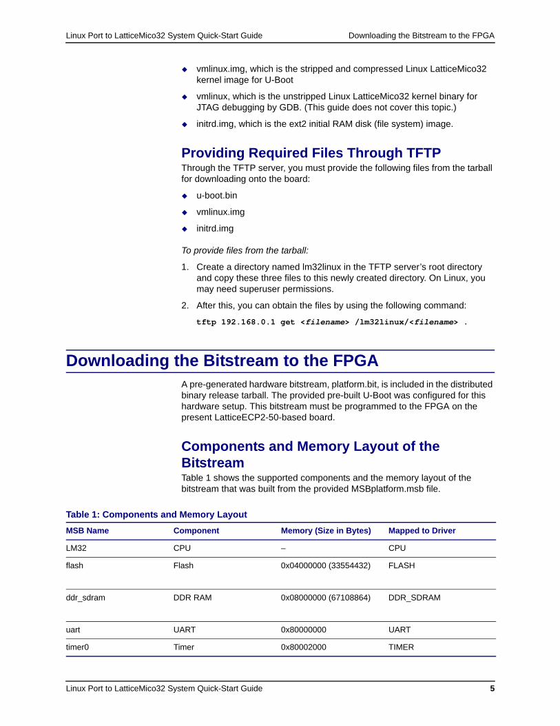
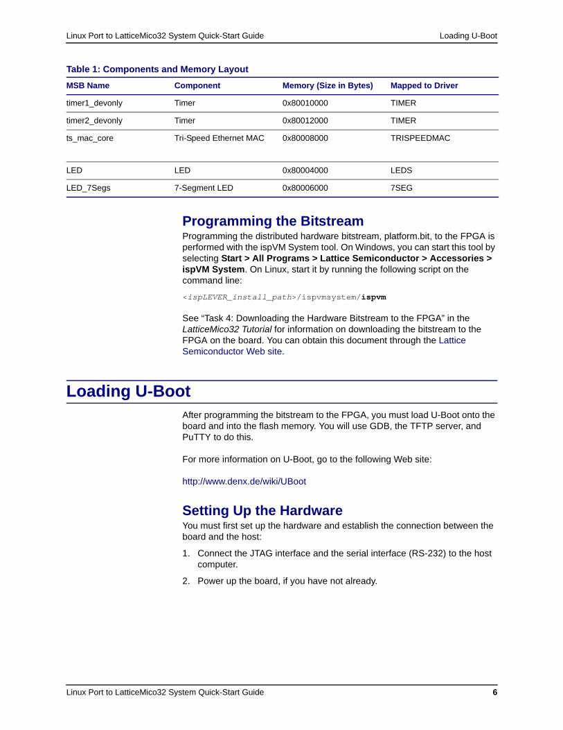
Components and Memory Layout of the BitstreamTable 1 shows the supported components and the memory layout of the bitstream that was built from the provided MSBplatform.msb file.
Table 1: Components and Memory Layout
MSB Name Component Memory (Size in Bytes) Mapped to Driver
LM32 CPU – CPU
flash Flash 0x04000000 (33554432) FLASH
ddr_sdram DDR RAM 0x08000000 (67108864) DDR_SDRAM
uart UART 0x80000000 UART
timer0 Timer 0x80002000 TIMER
Linux Port to LatticeMico32 System Quick-Start Guide Loading U-Boot
Linux Port to LatticeMico32 System Quick-Start Guide 6
Programming the BitstreamProgramming the distributed hardware bitstream, platform.bit, to the FPGA is performed with the ispVM System tool. On Windows, you can start this tool by selecting Start > All Programs > Lattice Semiconductor > Accessories > ispVM System. On Linux, start it by running the following script on the command line:
<ispLEVER_install_path>/ispvmsystem/ispvm
See “Task 4: Downloading the Hardware Bitstream to the FPGA” in the LatticeMico32 Tutorial for information on downloading the bitstream to the FPGA on the board. You can obtain this document through the Lattice Semiconductor Web site.
Loading U-BootAfter programming the bitstream to the FPGA, you must load U-Boot onto the board and into the flash memory. You will use GDB, the TFTP server, and PuTTY to do this.
For more information on U-Boot, go to the following Web site:
http://www.denx.de/wiki/UBoot
Setting Up the HardwareYou must first set up the hardware and establish the connection between the board and the host:
1. Connect the JTAG interface and the serial interface (RS-232) to the host computer.
2. Power up the board, if you have not already.
timer1_devonly Timer 0x80010000 TIMER
timer2_devonly Timer 0x80012000 TIMER
ts_mac_core Tri-Speed Ethernet MAC 0x80008000 TRISPEEDMAC
LED LED 0x80004000 LEDS
LED_7Segs 7-Segment LED 0x80006000 7SEG
Table 1: Components and Memory Layout
MSB Name Component Memory (Size in Bytes) Mapped to Driver
Linux Port to LatticeMico32 System Quick-Start Guide Loading U-Boot
Linux Port to LatticeMico32 System Quick-Start Guide 7
Setting Up the Remote Serial ConsoleAn application for setting up a remote serial console over a RS-232 serial connection is used to communicate with the board as soon as U-Boot is uploaded in order to set it up.
The following two sections describe how to configure PuTTY and HyperTerminal for this task. Only one of the two programs is needed, and although it is recommend that you use PuTTY (the accompanying screenshots will show the output in PuTTY), you can use HyperTerminal without limitation as well.
Setting Up PuTTYIt is recommended that you use PuTTY as the remote serial application. You can obtain it free at http://www.chiark.greenend.org.uk/~sgtatham/putty/. You must use version 0.59 or later.
To set up PuTTY:
1. Download the putty.exe file and run the program.
An installation of the software is not required.
Immediately after you start the application, the PuTTY Configuration dialog box appears.
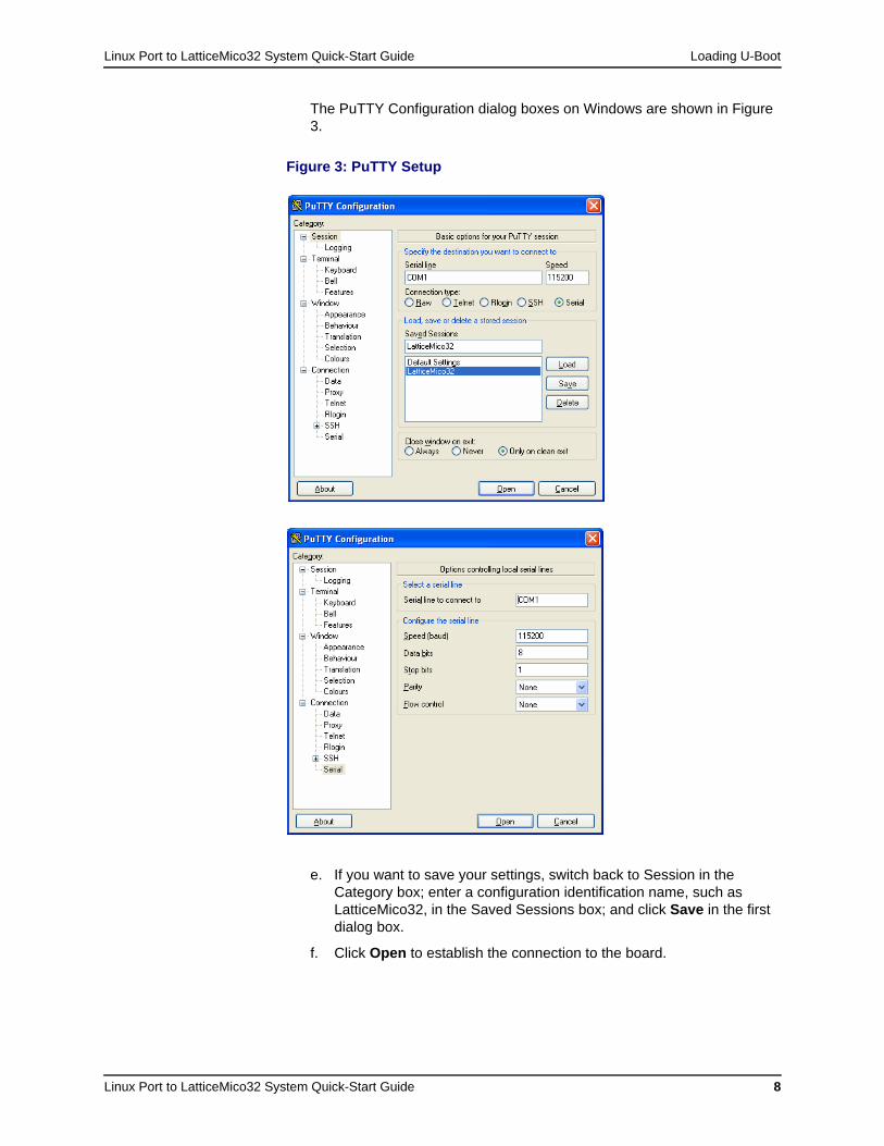
2. In the PuTTY Configuration dialog box, do the following:
a. Choose Serial as connection type.
b. In the Serial Line box on Windows, specify the COM port to which the board is connected. On Linux, the default serial port is /dev/ttyS0, and you must have “rw” permission.
c. In the Speed box, set the baud rate to 115200.
d. On the Category menu at the left, choose Serial (at the bottom of the list), and change the flow control setting to None.
Linux Port to LatticeMico32 System Quick-Start Guide Loading U-Boot
Linux Port to LatticeMico32 System Quick-Start Guide 8
The PuTTY Configuration dialog boxes on Windows are shown in Figure 3.
e. If you want to save your settings, switch back to Session in the Category box; enter a configuration identification name, such as LatticeMico32, in the Saved Sessions box; and click Save in the first dialog box.
f. Click Open to establish the connection to the board.
Figure 3: PuTTY Setup
Linux Port to LatticeMico32 System Quick-Start Guide Loading U-Boot
Linux Port to LatticeMico32 System Quick-Start Guide 9
The setup is now complete.
Setting Up HyperTerminal in WindowsAlthough it is recommended that you use PuTTY, you can also use HyperTerminal on Windows.
To set up HyperTerminal:
1. You can start HyperTerminal by selecting Start > All Programs > Accessories > Communications > HyperTerminal.
If the application is not installed on your computer, you can find it on the Windows installation CD. You can install it by using the Add or Remove Programs tool in the Control Panel.
2. After starting HyperTerminal, create a new connection. Provide a name that describes the connection, such as LatticeMico32, and use the COM port to which the board is connected (that is, “Connect using” should be set to one of the COM ports).
3. In the following dialog box, do the following:
a. Select a baud rate (that is, bits per second) of 115200.
b. Select 8 data bits.
c. Set parity to None.
d. Set stop bit to 1.
e. Set the flow control to None.
f. Confirm your settings by clicking OK.
Loading U-Boot into RAM by Using JTAG and GDBBefore writing U-Boot into flash memory, you must load it into RAM and start it from there.
To load U-Boot into RAM and start it:
1. If you are using Windows, start a new LatticeMico32 System SDK shell, as described in “Starting the LatticeMico32 System SDK Shell” on page 3. If you are using Linux, open a new shell terminal window.
Now you should have two shells opened, where the current working directory of the first shell is /lm32linux-<yyyymmdd>bin/, and the current working directory of the second one is /.
2. If you are using Windows, type TCP2JTAGVC2 in the second shell (current directory /) window and press Enter to start the application.
If you are using Linux, perform the following steps:
a. Make sure that a USB driver is installed (refer to <isptools_install_dir>/ispvmsystem/ispVMLinuxInstallation.pdf for information).
b. In a c-shell, source setup_lv.csh located in <isp_lever_install_dir>/ispcpld/bin directory.
Linux Port to LatticeMico32 System Quick-Start Guide Loading U-Boot
Linux Port to LatticeMico32 System Quick-Start Guide 10
c. Source LatticeMico32.csh (. ./ LatticeMico32.sh on the Korn shell), which is located in the <lm32_install_dir> directory.
d. Go to <lm32_install_dir>/gtools/bin and execute by entering TCP2JTAGVC2.
This server, which is started in background, provides a proxy between the JTAG interface and the GDB client.
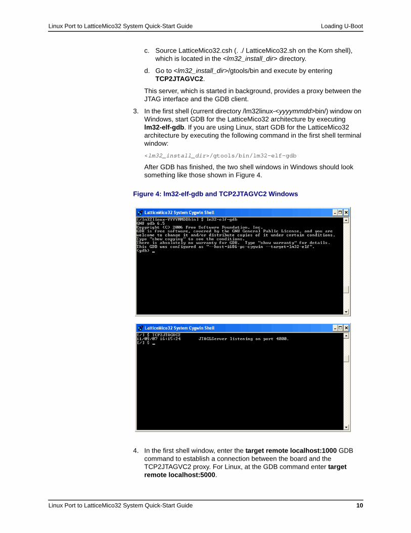
3. In the first shell (current directory /lm32linux-<yyyymmdd>bin/) window on Windows, start GDB for the LatticeMico32 architecture by executing lm32-elf-gdb. If you are using Linux, start GDB for the LatticeMico32 architecture by executing the following command in the first shell terminal window:
<lm32_install_dir>/gtools/bin/lm32-elf-gdb
After GDB has finished, the two shell windows in Windows should look something like those shown in Figure 4.
4. In the first shell window, enter the target remote localhost:1000 GDB command to establish a connection between the board and the TCP2JTAGVC2 proxy. For Linux, at the GDB command enter target remote localhost:5000.
Figure 4: lm32-elf-gdb and TCP2JTAGVC2 Windows
Linux Port to LatticeMico32 System Quick-Start Guide Loading U-Boot
Linux Port to LatticeMico32 System Quick-Start Guide 11
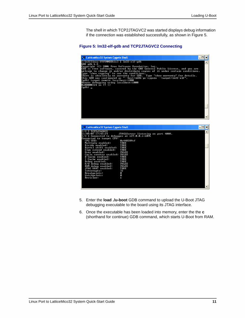
The shell in which TCP2JTAGVC2 was started displays debug information if the connection was established successfully, as shown in Figure 5.
5. Enter the load ./u-boot GDB command to upload the U-Boot JTAG debugging executable to the board using its JTAG interface.
6. Once the executable has been loaded into memory, enter the the c (shorthand for continue) GDB command, which starts U-Boot from RAM.
Figure 5: lm32-elf-gdb and TCP2JTAGVC2 Connecting

Linux Port to LatticeMico32 System Quick-Start Guide Loading U-Boot
Linux Port to LatticeMico32 System Quick-Start Guide 12
PuTTY, which you have already configured, should show the output of the U-Boot boot loader start-up sequence and should present you the U-Boot command-line interface, as shown in Figure 6.
Configuring the Network InterfaceNow that you have started the U-Boot for JTAG debugging, the “real” U-Boot should be programmed into flash memory. But first you must configure the board’s network interface through U-Boot to be able to obtain the U-Boot binary using the TFTP server.
Setting Environment Variables in U-BootSet environment variables in U-Boot with the setenv command, using the following syntax:
setenv <variables> <value>
See “Configuring the Network Interface in U-Boot” on page 23 of the Linux Port to LatticeMico32 System Reference Guide for information on the environment variables that you can use to configure the network interface in U-Boot.
For example, to set the ipaddr variable to 192.168.0.10, you would type this:
setenv ipaddr 192.168.0.10
You can permanently save environment variables by using the saveenv command, which writes the configuration to a protected sector in the flash memory of the board and is loaded each time U-Boot starts.
Figure 6: U-Boot Output and CLI in PuTTY
Linux Port to LatticeMico32 System Quick-Start Guide Loading U-Boot
Linux Port to LatticeMico32 System Quick-Start Guide 13
Checking Environment Variables in U-BootYou can use the printenv and bdinfo commands on the console command line to check the U-Boot settings:
printenv Prints all set environment variables. The syntax is as follows:
printenv
Here is an example:
lm32# printenv
bootdelay=5baudrate=115200ethaddr=12:34:56:78:ab:cdethact=lm32MAC#0filesize=1000040fileaddr=8000000stdin=serialstdout=serialstderr=serialipaddr=192.168.0.100netmask=255.255.255.0serverip=192.168.0.1
bdinfo Provides basic information on the board, such as:
Flash memory range (address and size)
Ethernet MAC address
IP address
UART baud rate
Here is an example of the board information provided by the bdinfo command:
lm32# bdinfoboot_params = 0x00000000memstart = 0x00000000memsize = 0x00000000flashstart = 0x04000000flashsize = 0x02000000flashoffset = 0x00000000ethaddr = 92:68:00:10:00:00ip_addr = 192.168.0.100baudrate = 115200 bps
The U-Boot startup banner provides comprehensive information on the board configuration. Following is a sample banner:
U-Boot 1.2.0 (Jan 27 2008 - 23:39:54) [Theobroma Systems]
LatticeMico32 board configuration: Device | Base Address | Additional information ---------------+--------------+-------------------------- CPU 0 | | Frequency: 75000000 Hz Flash 0 | 0x04000000 | Size: 33554432 (32 MB) DDR SDRAM 0 | 0x08000000 | Size: 67108864 (64 MB) Timer 0 | 0x80002000 |
Linux Port to LatticeMico32 System Quick-Start Guide Loading U-Boot
Linux Port to LatticeMico32 System Quick-Start Guide 14
Timer 1 | 0x80010000 | Timer 2 | 0x80012000 | UART 0 | 0x80000000 | Baud Rate: 115200 LEDs 0 | 0x80004000 | 7Segment 0 | 0x80006000 | TriSpeedMAC 0 | 0x80008000 |
LM32 configuration options: Hardware multiplier: enabled Hardware divider: enabled Hardware barrel-shifer: enabled Sign-extension instructions: disabled Cycle counter CSR: disabled Instruction cache: enabled Data cache: enabled
lm32mac version 0x10000 @ 0x80008000lm32MAC#0In: serialOut: serialErr: serial
Networking Environment VariablesThe environment variables shown in Table 2 are used to configure the network interface in U-Boot.
Changes made to the configuration are applied instantly.
Table 2: Networking Environment Variables
Variable Description
ethaddr Sets the MAC address of the Ethernet interface (for example, 12:34:56:78:ab:cd).
ipaddr Sets the IP address of the Ethernet interface (for example, 192.168.0.100).
netmask Sets the net mask (for example, 255.255.0.0).
serverip Sets the IP address of the server on which the TFTP server resides, that is, the server from which the binaries are fetched.
Note
You can reset the ethaddr environment variable only once for each board. If the MAC address has been changed once, U-Boot will refuse further change requests. See “Changing the Ethernet MAC Address” on page 15 for instructions on changing the MAC address.
The dhcp U-Boot command for obtaining the configuration from a network DHCP server is not available in this build. You must configure the network interface manually.

Linux Port to LatticeMico32 System Quick-Start Guide Loading U-Boot
Linux Port to LatticeMico32 System Quick-Start Guide 15
Example ConfigurationThe board’s network interface configuration depends on the network setup of your environment, so only an example configuration can be given at this point. You will probably have to adapt the parameters to suit your network setup.
Here is an example configuration with an IP address of 192.168.0.100, a net mask of 255.255.255.0, and a server IP address of 192.168.0.1:
lm32# setenv ipaddr 192.168.0.100lm32# setenv netmask 255.255.255.0lm32# setenv serverip 192.168.0.1lm32# saveenv
You can use the ping command in U-Boot to verify connectivity to the server. However, U-Boot does not reply to ping requests, so you cannot ping the LatticeMico32 board running U-Boot from the server.
Figure 7 shows the configuration of the example network interface.
Changing the Ethernet MAC AddressThe default Ethernet MAC address for the LatticeMico32 Tri-Speed MAC is 12:34:56:78:ab:cd. You can override this default MAC address by setting the ethaddr environment variable. For example, to set the MAC address to 02:00:01:02:03:04, enter the following command:
setenv ethaddr 02:00:01:02:03:04
Once you change the default MAC address and save the environment variables with the saveenv command, you cannot program another MAC address by simply using the setenv ethaddr command.
Figure 7: Example Network Interface Configuration

Linux Port to LatticeMico32 System Quick-Start Guide Loading U-Boot
Linux Port to LatticeMico32 System Quick-Start Guide 16
To change a programmed MAC address for the LatticeECP2 board:
1. Unlock the last sector (sector 127) of the CFI flash bank 1 by using the following command:
protect off 1:127
You can use the flinfo command in U-Boot to obtain CFI flash information for the LatticeECP2 board's CFI flash configuration if your board’s flash configuration is different.
2. Erase the last sector using the following command:
erase 1:127
3. Restart U-Boot, which will use the default settings. Now you can re-program the MAC address. After you erase the flash, all environment variables are erased, so you must reprogram the environment variables that you explicitly set earlier.
Writing U-Boot into Flash MemoryStarting U-Boot from flash memory eliminates the need to use GDB and TCP2JTAGVC2 every time the board is power-cycled.
To use TFTP to write U-Boot to flash memory once it is running:
1. To obtain the U-Boot binary through the TFTP server, copy the u-boot.bin file, which is the stripped U-Boot binary, to the TFTP /lm32linux/ directory, if you have not already.
2. Set the serverip environment variable, if you have not already.
3. Load the U-Boot binary into an empty section of SRAM by using the tftp command. The following example shows the binary loaded to the 0x08000000 address, since it is the base address of the SRAM and the subsequent region should be empty.
lm32# tftp 08000000 /lm32linux/u-boot.bin
4. Erase the first two sections of the flash memory (0x04000000 to 0x0407FFFF) to which the binary will be stored by using the erase command:
lm32# erase 04000000 0407ffff
5. Copy the binary from the address that you have loaded in SRAM (0x08000000) to its destination at the beginning of the flash memory by using the cp.b command:
lm32# cp.b 08000000 04000000 00080000
This command copies 0x80000 bytes, starting at 0x08000000 (SRAM base address) and ending at 0x04000000 (flash memory base address)

Linux Port to LatticeMico32 System Quick-Start Guide Booting the Linux Port to LatticeMico32
Linux Port to LatticeMico32 System Quick-Start Guide 17
Figure 8 shows the process of writing U-Boot into flash memory.
Starting U-Boot from Flash MemoryIf you have the FPGA bitstream programmed in the SPI flash, power-cycle the board or press the Program button, then press the Reset button on the LatticeECP2 board to start U-Boot automatically from flash memory.
U-Boot’s early initialization assembler code copies the boot loader to the 0x0C0DC000 address in SRAM and starts it from there each time that you reset the board.
Booting the Linux Port to LatticeMico32Now that U-Boot will start each time the board is reset, you are ready to boot the Linux port to the LatticeMico32 kernel by using the TFTP server.
At first, the boot options for the Linux kernel must be set in U-Boot. Then the kernel image and the initial RAM disk (initrd) are loaded from TFTP into the RAM and started directly from there. Although this process is enough to run Linux, you will program both images into the flash memory to run Linux independently of the TFTP server.
Figure 8: Writing U-Boot into Flash Output
Linux Port to LatticeMico32 System Quick-Start Guide Booting the Linux Port to LatticeMico32
Linux Port to LatticeMico32 System Quick-Start Guide 18
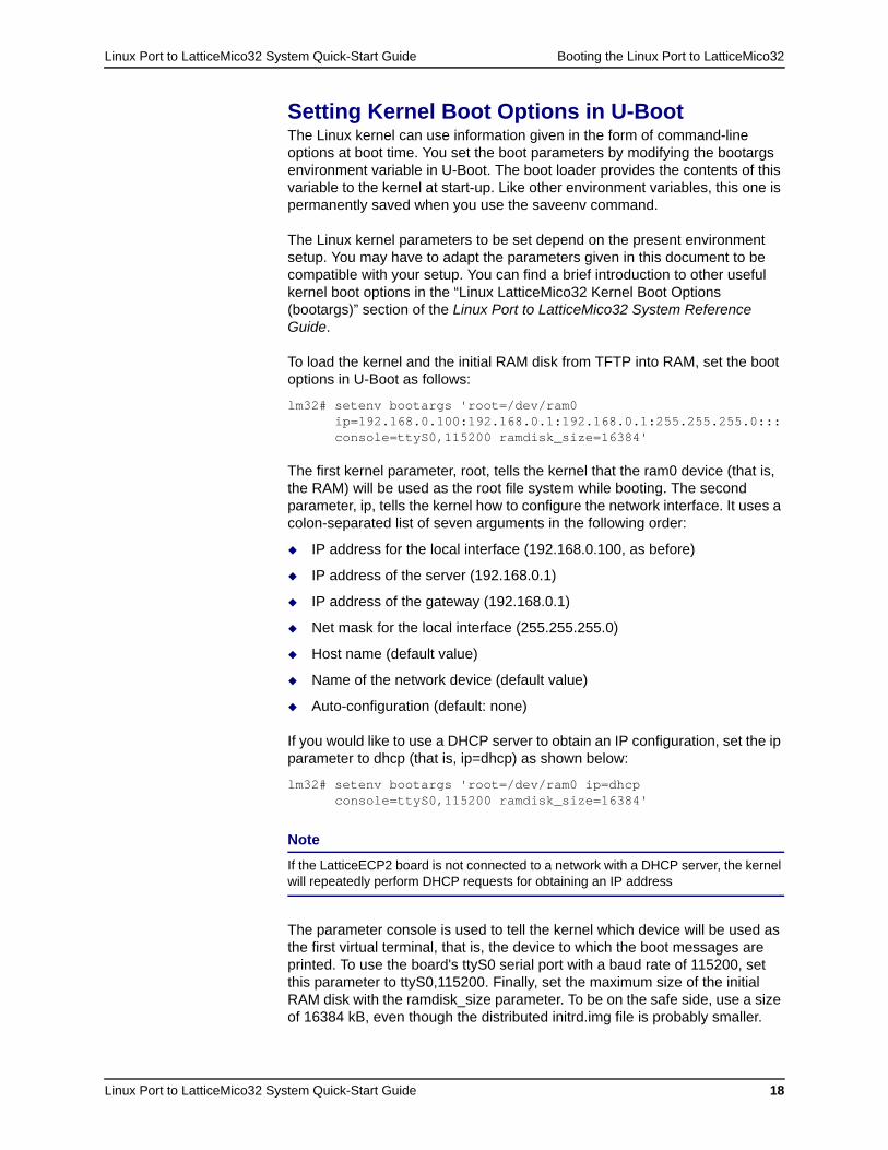
Setting Kernel Boot Options in U-BootThe Linux kernel can use information given in the form of command-line options at boot time. You set the boot parameters by modifying the bootargs environment variable in U-Boot. The boot loader provides the contents of this variable to the kernel at start-up. Like other environment variables, this one is permanently saved when you use the saveenv command.
The Linux kernel parameters to be set depend on the present environment setup. You may have to adapt the parameters given in this document to be compatible with your setup. You can find a brief introduction to other useful kernel boot options in the “Linux LatticeMico32 Kernel Boot Options (bootargs)” section of the Linux Port to LatticeMico32 System Reference Guide.
To load the kernel and the initial RAM disk from TFTP into RAM, set the boot options in U-Boot as follows:
lm32# setenv bootargs 'root=/dev/ram0ip=192.168.0.100:192.168.0.1:192.168.0.1:255.255.255.0::: console=ttyS0,115200 ramdisk_size=16384'
The first kernel parameter, root, tells the kernel that the ram0 device (that is, the RAM) will be used as the root file system while booting. The second parameter, ip, tells the kernel how to configure the network interface. It uses a colon-separated list of seven arguments in the following order:
IP address for the local interface (192.168.0.100, as before)
IP address of the server (192.168.0.1)
IP address of the gateway (192.168.0.1)
Net mask for the local interface (255.255.255.0)
Host name (default value)
Name of the network device (default value)
Auto-configuration (default: none)
If you would like to use a DHCP server to obtain an IP configuration, set the ip parameter to dhcp (that is, ip=dhcp) as shown below:
lm32# setenv bootargs 'root=/dev/ram0 ip=dhcp console=ttyS0,115200 ramdisk_size=16384'
The parameter console is used to tell the kernel which device will be used as the first virtual terminal, that is, the device to which the boot messages are printed. To use the board's ttyS0 serial port with a baud rate of 115200, set this parameter to ttyS0,115200. Finally, set the maximum size of the initial RAM disk with the ramdisk_size parameter. To be on the safe side, use a size of 16384 kB, even though the distributed initrd.img file is probably smaller.
Note
If the LatticeECP2 board is not connected to a network with a DHCP server, the kernel will repeatedly perform DHCP requests for obtaining an IP address

Linux Port to LatticeMico32 System Quick-Start Guide Booting the Linux Port to LatticeMico32
Linux Port to LatticeMico32 System Quick-Start Guide 19
Loading the Kernel and the Initial RAM Disk Through TFTPYou must configure U-Boot to load the kernel image and the initial RAM disk from TFTP to fixed locations in RAM and use these locations to boot from. Use the bootcmd environment variable in U-Boot to perform this configuration.
Set the bootcmd environment variable and its parameters as in this example:
lm32# setenv bootcmd 'tftp 0x08200000 /lm32linux/vmlinux.img; tftp 0x08400000 /lm32linux/initrd.img; bootm 08200000 08400000'
In this example, the bootcmd environment variable includes three single U-Boot parameters:
The first one (tftp 0x08200000 /lm32linux/vmlinux.img;) downloads the vmlinux.img kernel image from the TFTP server directly to RAM at the 0x08200000 address.
The second one (tftp 0x08400000 /lm32linux/initrd.img;) downloads the initial RAM disk initrd.img to the 0x08400000 RAM address.
The third command (bootm 08200000 08400000) instructs the kernel to boot from memory at the 0x08200000 address and use the initial RAM disk at 0x08400000.
These commands are executed in order right after the boot command is executed or the board is reset. If the bootcmd environment variable is set and permanently saved to flash memory with the saveenv command, the boot command will be executed automatically each time the board is reset after starting the boot loader.
After setting the bootcmd environment variable and parameters, save the configuration by using the saveenv command:
lm32# saveenv
Linux Port to LatticeMico32 System Quick-Start Guide Booting the Linux Port to LatticeMico32
Linux Port to LatticeMico32 System Quick-Start Guide 20
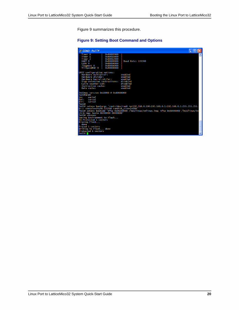
Figure 9 summarizes this procedure.
Figure 9: Setting Boot Command and Options
Linux Port to LatticeMico32 System Quick-Start Guide Booting the Linux Port to LatticeMico32
Linux Port to LatticeMico32 System Quick-Start Guide 21
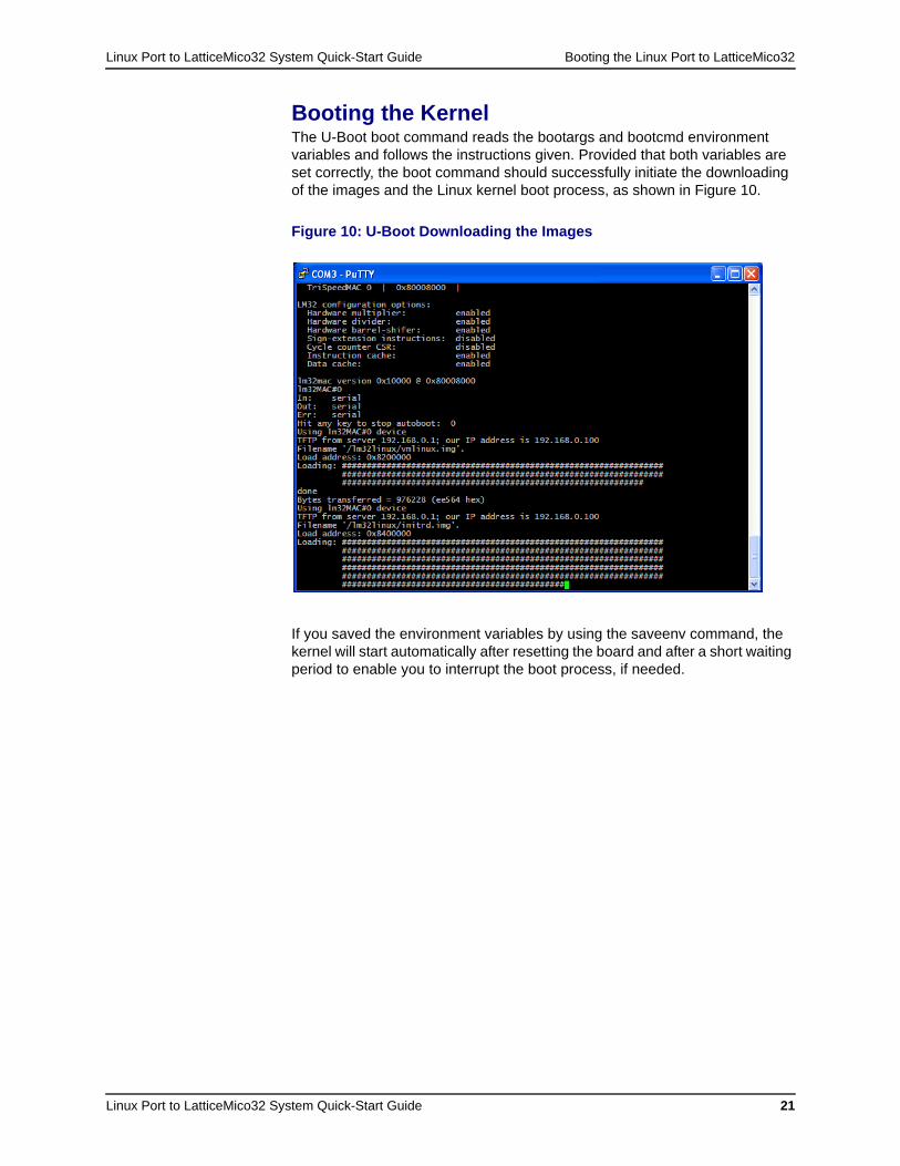
Booting the KernelThe U-Boot boot command reads the bootargs and bootcmd environment variables and follows the instructions given. Provided that both variables are set correctly, the boot command should successfully initiate the downloading of the images and the Linux kernel boot process, as shown in Figure 10.
If you saved the environment variables by using the saveenv command, the kernel will start automatically after resetting the board and after a short waiting period to enable you to interrupt the boot process, if needed.
Figure 10: U-Boot Downloading the Images
Linux Port to LatticeMico32 System Quick-Start Guide Booting the Linux Port to LatticeMico32
Linux Port to LatticeMico32 System Quick-Start Guide 22
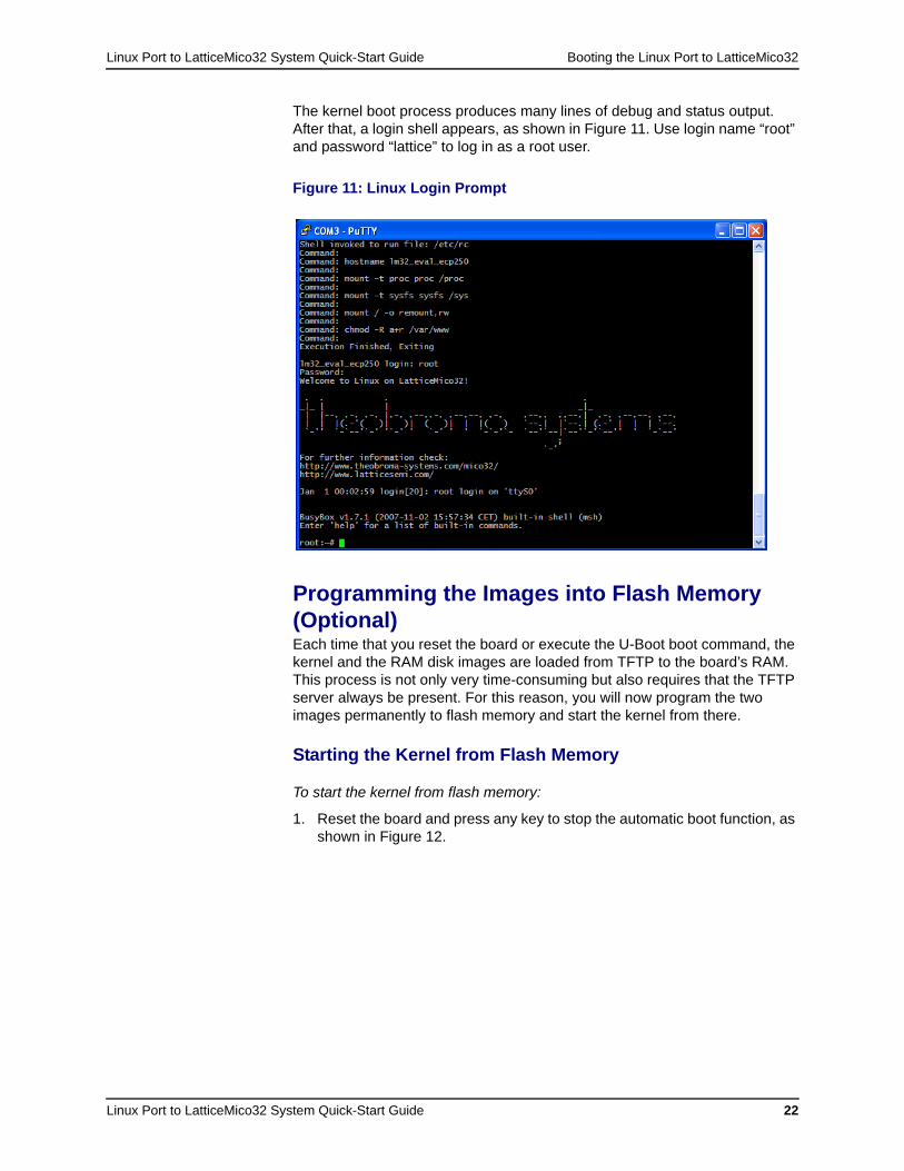
The kernel boot process produces many lines of debug and status output. After that, a login shell appears, as shown in Figure 11. Use login name “root” and password “lattice” to log in as a root user.
Programming the Images into Flash Memory (Optional)Each time that you reset the board or execute the U-Boot boot command, the kernel and the RAM disk images are loaded from TFTP to the board’s RAM. This process is not only very time-consuming but also requires that the TFTP server always be present. For this reason, you will now program the two images permanently to flash memory and start the kernel from there.
Starting the Kernel from Flash Memory
To start the kernel from flash memory:
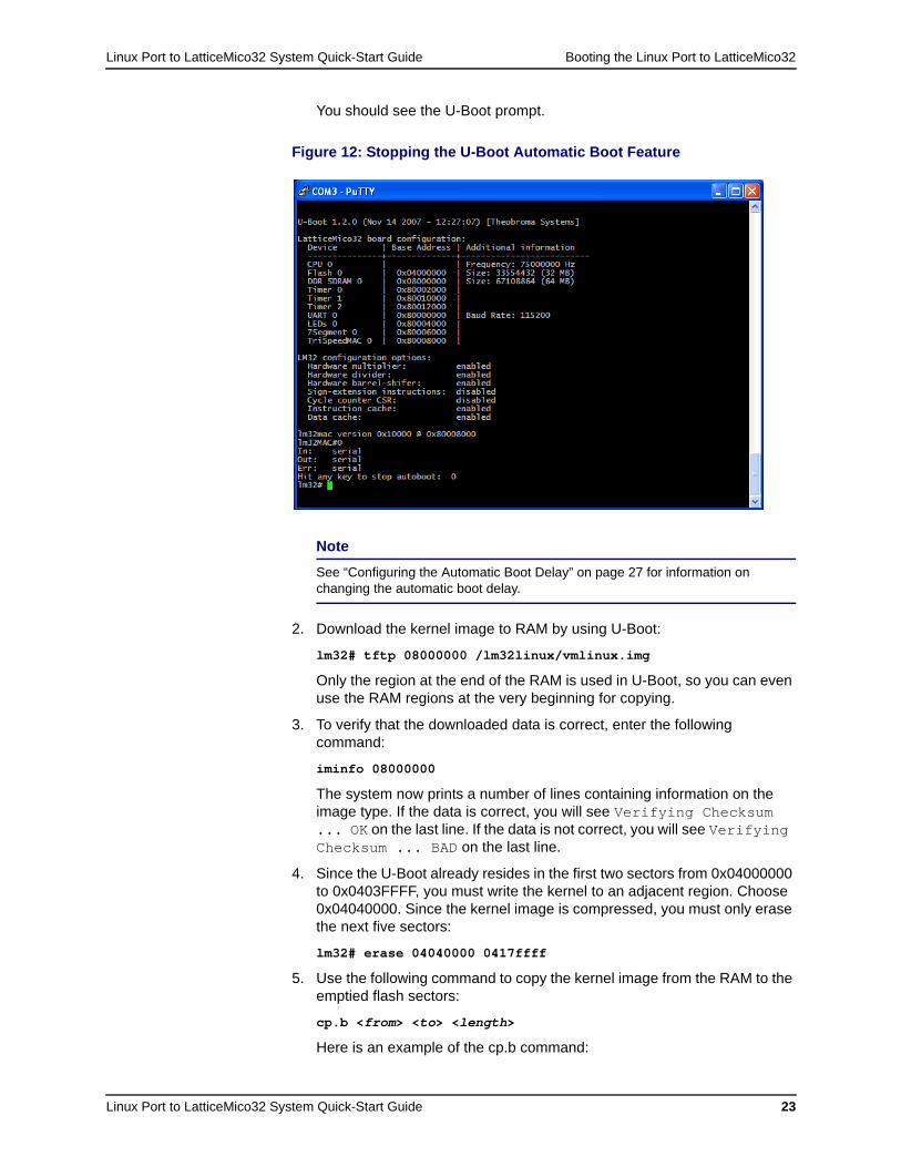
1. Reset the board and press any key to stop the automatic boot function, as shown in Figure 12.
Figure 11: Linux Login Prompt
Linux Port to LatticeMico32 System Quick-Start Guide Booting the Linux Port to LatticeMico32
Linux Port to LatticeMico32 System Quick-Start Guide 23
You should see the U-Boot prompt.
2. Download the kernel image to RAM by using U-Boot:
lm32# tftp 08000000 /lm32linux/vmlinux.img
Only the region at the end of the RAM is used in U-Boot, so you can even use the RAM regions at the very beginning for copying.
3. To verify that the downloaded data is correct, enter the following command:
iminfo 08000000
The system now prints a number of lines containing information on the image type. If the data is correct, you will see Verifying Checksum ... OK on the last line. If the data is not correct, you will see Verifying Checksum ... BAD on the last line.
4. Since the U-Boot already resides in the first two sectors from 0x04000000 to 0x0403FFFF, you must write the kernel to an adjacent region. Choose 0x04040000. Since the kernel image is compressed, you must only erase the next five sectors:
lm32# erase 04040000 0417ffff
5. Use the following command to copy the kernel image from the RAM to the emptied flash sectors:
cp.b <from> <to> <length>
Here is an example of the cp.b command:
Figure 12: Stopping the U-Boot Automatic Boot Feature
Note
See “Configuring the Automatic Boot Delay” on page 27 for information on changing the automatic boot delay.
Linux Port to LatticeMico32 System Quick-Start Guide Booting the Linux Port to LatticeMico32
Linux Port to LatticeMico32 System Quick-Start Guide 24
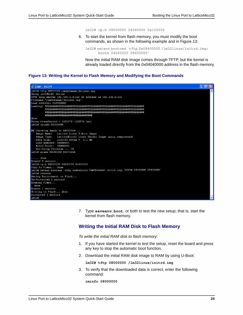
lm32# cp.b 08000000 04040000 0x120000
6. To start the kernel from flash memory, you must modify the boot commands, as shown in the following example and in Figure 13:
lm32# setenv bootcmd 'tftp 0x08400000 /lm32linux/initrd.img; bootm 04040000 08400000'
Now the initial RAM disk image comes through TFTP, but the kernel is already loaded directly from the 0x04040000 address in the flash memory.
7. Type saveenv, boot, or both to test the new setup; that is, start the kernel from flash memory.
Writing the Initial RAM Disk to Flash Memory
To write the initial RAM disk to flash memory:
1. If you have started the kernel to test the setup, reset the board and press any key to stop the automatic boot function.
2. Download the initial RAM disk image to RAM by using U-Boot:
lm32# tftp 08000000 /lm32linux/initrd.img
3. To verify that the downloaded data is correct, enter the following command:
iminfo 08000000
Figure 13: Writing the Kernel to Flash Memory and Modifying the Boot Commands
Linux Port to LatticeMico32 System Quick-Start Guide Booting the Linux Port to LatticeMico32
Linux Port to LatticeMico32 System Quick-Start Guide 25
The system now prints a number of lines containing information on the image type. If the data is correct, you will see Verifying Checksum ... OK on the last line. If the data is not correct, you will see Verifying Checksum ... BAD on the last line.
4. Since the region 0x04000000 to 0x0417FFFF is already reserved for U-Boot and the kernel image, you will save the RAM disk image to 0x04240000. The maximum size of the RAM disk image is 0x01000040 (16 MB plus a 64-byte header), so you must erase the adjacent 0x01040000 bytes (65 sectors) of the flash memory:
lm32# erase 04240000 0527ffff
5. Use the following command to copy the image from RAM to the flash sectors:
cp.b <from> <to> <length>)
Here is an example:
lm32# cp.b 08000000 04240000 01040000
This task is very time-consuming and will take about 20 to 30 minutes to complete.
6. Because the kernel cannot use the RAM disk image directly from flash memory, you must copy the image from flash to RAM before booting the kernel. Use the U-Boot boot commands for this purpose:
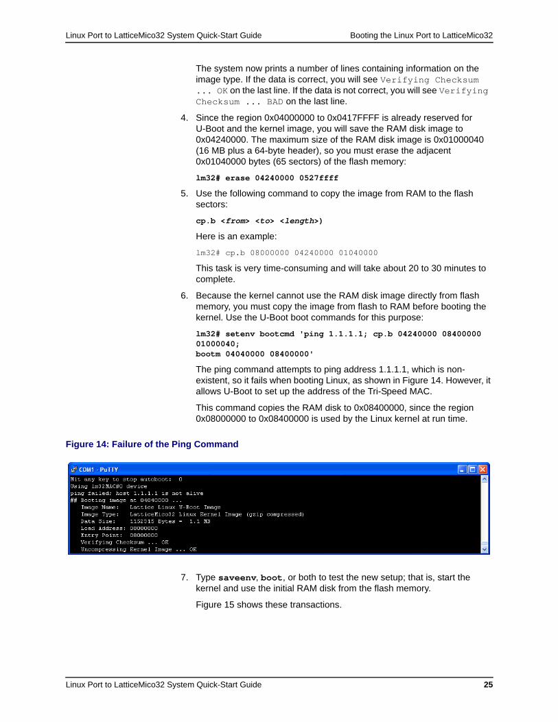
lm32# setenv bootcmd 'ping 1.1.1.1; cp.b 04240000 08400000 01000040; bootm 04040000 08400000'
The ping command attempts to ping address 1.1.1.1, which is non-existent, so it fails when booting Linux, as shown in Figure 14. However, it allows U-Boot to set up the address of the Tri-Speed MAC.
This command copies the RAM disk to 0x08400000, since the region 0x08000000 to 0x08400000 is used by the Linux kernel at run time.
7. Type saveenv, boot, or both to test the new setup; that is, start the kernel and use the initial RAM disk from the flash memory.
Figure 15 shows these transactions.
Figure 14: Failure of the Ping Command

Linux Port to LatticeMico32 System Quick-Start Guide Booting the Linux Port to LatticeMico32
Linux Port to LatticeMico32 System Quick-Start Guide 26
After you complete this task, the LatticeECP2-50 development board boots a fully functional Linux LatticeMico32 kernel and loads the file system containing the provided userland applications independently of any TFTP server.
Figure 15: Writing the initrd Image to Flash Memory and Modifying the Boot Commands
Linux Port to LatticeMico32 System Quick-Start Guide Testing the Setup
Linux Port to LatticeMico32 System Quick-Start Guide 27
Configuring the Automatic Boot DelayYou can change the automatic boot delay at run time.
To change the automatic boot delay:
1. Specify the new automatic boot delay by entering the following:
setenv bootdelay <number_of_seconds>
Here is an example that sets the automatic boot delay to 10 seconds:
setenv bootdelay 10
2. Save this configuration by entering the following:
saveenv
3. Verify the setting by printing the environment variable:
printenv
To configure the default automatic boot delay for the U-Boot build:
1. Edit the ECP250full.h header file, which is located in the u-boot/include/configs/ directory under the sources installation directory, to modify the following preprocessor definition, as in this example:
#define CONFIG_BOOTDELAY 5
2. Rebuild U-Boot.
Testing the SetupYou should now have a board that starts U-Boot and boots the Linux kernel with the initial RAM disk file system automatically after a power cycle or a reset. Now you are free to test and evaluate the Linux port to LatticeMico32 however you want to. Following are brief descriptions of the tools that you can use in testing and evaluating the Linux port to LatticeMico32.
Linux Port to LatticeMico32 System Quick-Start Guide Testing the Setup
Linux Port to LatticeMico32 System Quick-Start Guide 28
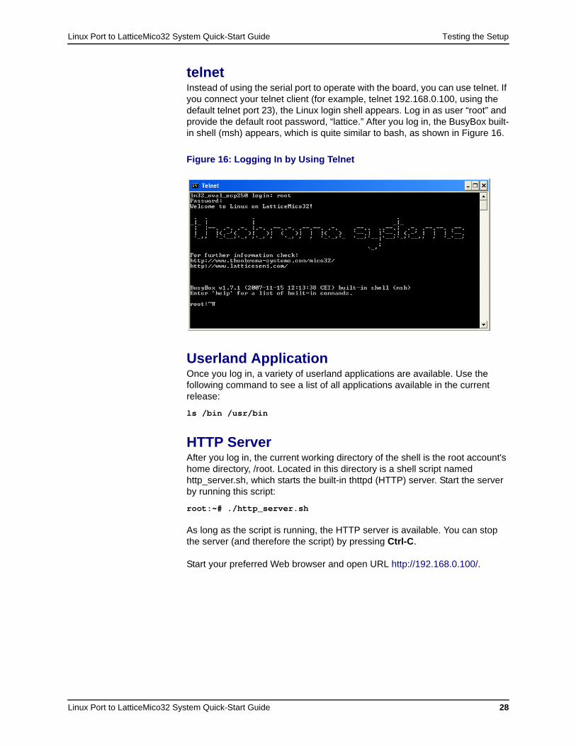
telnetInstead of using the serial port to operate with the board, you can use telnet. If you connect your telnet client (for example, telnet 192.168.0.100, using the default telnet port 23), the Linux login shell appears. Log in as user “root” and provide the default root password, “lattice.” After you log in, the BusyBox built-in shell (msh) appears, which is quite similar to bash, as shown in Figure 16.
Userland ApplicationOnce you log in, a variety of userland applications are available. Use the following command to see a list of all applications available in the current release:
ls /bin /usr/bin
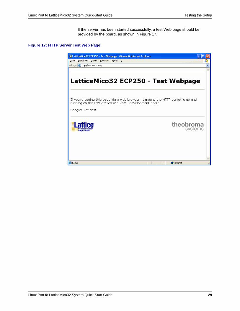
HTTP ServerAfter you log in, the current working directory of the shell is the root account's home directory, /root. Located in this directory is a shell script named http_server.sh, which starts the built-in thttpd (HTTP) server. Start the server by running this script:
root:~# ./http_server.sh
As long as the script is running, the HTTP server is available. You can stop the server (and therefore the script) by pressing Ctrl-C.
Start your preferred Web browser and open URL http://192.168.0.100/.
Figure 16: Logging In by Using Telnet
Linux Port to LatticeMico32 System Quick-Start Guide Testing the Setup
Linux Port to LatticeMico32 System Quick-Start Guide 29
If the server has been started successfully, a test Web page should be provided by the board, as shown in Figure 17.
Figure 17: HTTP Server Test Web Page
Linux Port to LatticeMico32 System Quick-Start Guide Testing the Setup
Linux Port to LatticeMico32 System Quick-Start Guide 30
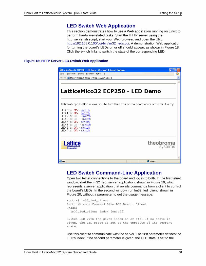
LED Switch Web ApplicationThis section demonstrates how to use a Web application running on Linux to perform hardware-related tasks. Start the HTTP server using the http_server.sh script, start your Web browser, and open the URL http://192.168.0.100/cgi-bin/lm32_leds.cgi. A demonstration Web application for turning the board’s LEDs on or off should appear, as shown in Figure 18. Click the switch links to switch the state of the corresponding LED.
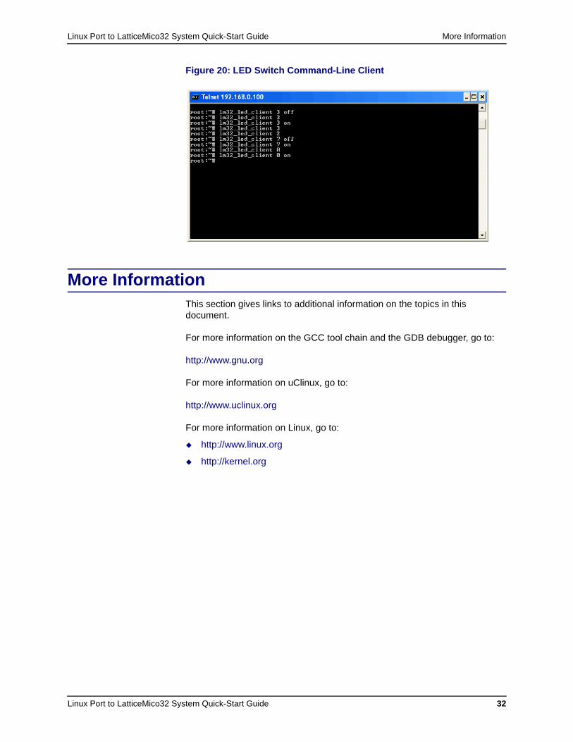
LED Switch Command-Line ApplicationOpen two telnet connections to the board and log in to both. In the first telnet window, start the lm32_led_server application, shown in Figure 19, which represents a server application that awaits commands from a client to control the board’s LEDs. In the second window, run lm32_led_client, shown in Figure 20, without a parameter to get the usage message:
root:~# lm32_led_clientLatticeMico32 Command-Line LED Demo - ClientUsage:
lm32_led_client index [on|off]
Switch LED with the given index on or off. If no state is given, the LED state is set to the opposite of its current state.
Use this client to communicate with the server. The first parameter defines the LED’s index. If no second parameter is given, the LED state is set to the
Figure 18: HTTP Server LED Switch Web Application
Linux Port to LatticeMico32 System Quick-Start Guide Testing the Setup
Linux Port to LatticeMico32 System Quick-Start Guide 31
opposite of its current state. To explicitly set the state, use the second parameter: on tells the server to set the LED, and off tells the server to turn the LED off.
Here are some example client calls:
root:~# lm32_led_client 3 offroot:~# lm32_led_client 3 root:~# lm32_led_client 3 onroot:~# lm32_led_client 3 root:~# lm32_led_client 2root:~# lm32_led_client 7 offroot:~# lm32_led_client 7 on root:~# lm32_led_client 0 root:~# lm32_led_client 0 on
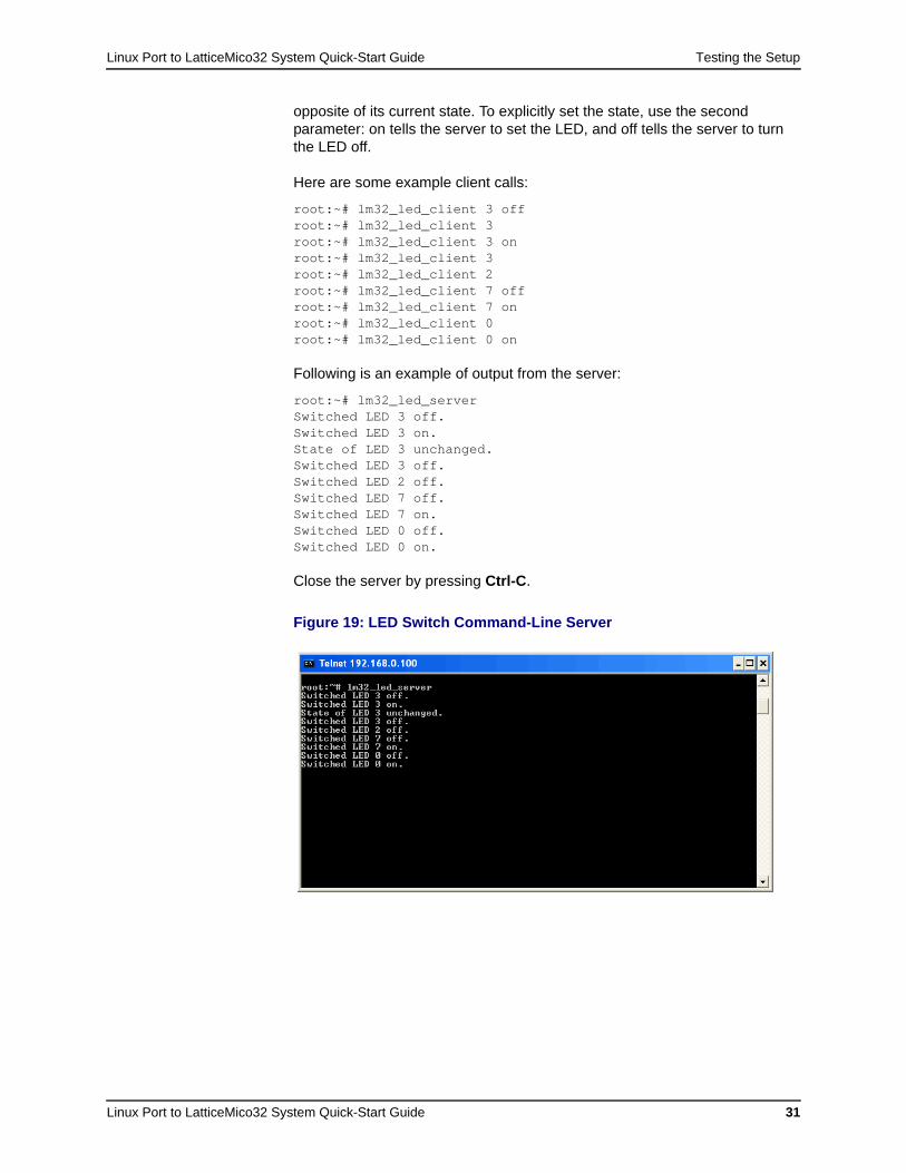
Following is an example of output from the server:
root:~# lm32_led_server Switched LED 3 off.Switched LED 3 on.State of LED 3 unchanged.Switched LED 3 off.Switched LED 2 off.Switched LED 7 off.Switched LED 7 on.Switched LED 0 off.Switched LED 0 on.
Close the server by pressing Ctrl-C.
Figure 19: LED Switch Command-Line Server
Linux Port to LatticeMico32 System Quick-Start Guide More Information
Linux Port to LatticeMico32 System Quick-Start Guide 32
More InformationThis section gives links to additional information on the topics in this document.
For more information on the GCC tool chain and the GDB debugger, go to:
http://www.gnu.org
For more information on uClinux, go to:
http://www.uclinux.org
For more information on Linux, go to:
http://www.linux.org
http://kernel.org
Figure 20: LED Switch Command-Line Client
Linux Port to LatticeMico32 System Quick-Start Guide 33
Index
Aautomatic boot delay 27
Bbash shell 28bdinfo command 13binary distribution tarball 3, 4boot command 21, 22boot delay 27bootargs environment variable 18, 21bootcmd environment variable 19, 21BusyBox built-in shell 28
CCOM port 7, 9Cygwin 2
Ddhcp command 14DHCP server 14, 18downloading bitstream to FPGA 5
Eethaddr environment variable 14, 15Ethernet MAC address 13, 14, 15
Fflash memory
starting Linux kernel from 22starting U-Boot from 17writing initial RAM disk to 24writing U-Boot to 16
flinfo command 16
GGDB 5, 10, 16
HHTTP server 28http_server.sh script 30HyperTerminal 3, 9
Iiminfo command 23, 24initrd.img image 5, 18, 19IP address 14ip parameter 18ipaddr environment variable 12, 14ispVM System 2
JJTAG debugging 5, 12JTAG debugging executable 11JTAG interface 6, 11
LLED switch command-line application 30LED switch Web application 30Linux kernel
booting 21loading image and RAM disk 19setting boot options in U-Boot 17starting from flash memory 22
Linux port to LatticeMico32 17lm32-elf-gdb 2logging in as root 22
MMAC address see Ethernet MAC address
Index
Linux Port to LatticeMico32 System Quick-Start Guide 34
MSBplatform.msb file 4, 5msh shell 28
Nnet mask 14netmask environment variable 14network interface 12
PPicocom 3platform.bit file 4, 5pre-generated bitstream 1
components and memory layout 5downloading to FPGA 5, 6using ispVM System to download to board 2
printenv command 13PuTTY
output of U-Boot start-up sequence 12setting up to load U-Boot 7source 3
PuTTY Configuration dialog box 7, 8putty.exe file 7
RRAM disk
initrd.img image 5, 19loading from TFTP to RAM 17, 19, 22setting size of initial 18writing to flash memory 24
ramdisk_size kernel parameter 18README file 4remote serial console 3, 7root kernel parameter 18RS-232 connection 3, 6, 7
Ssaveenv command 12, 18, 19, 21SDK shell 2, 3, 4, 9serial console 3, 7serverip environment variable 14, 16setenv command 12
TTCP2JTAGVC2 2, 11, 16telnet 28TFTP server
booting Linux port to LatticeMico32 17downloading files from tarball 5IP address 14IP address of 2obtaining U-Boot binary 12, 16purpose 2setting up with Cygwin 2sources 2
thttpd HTTP server 28
UU-Boot
checking settings of environment variables 13configuirng network interface 12downloading initial RAM disk image 24environment variables available in 14loading 6loading into RAM 9loading kernel image and RAM disk 19pre-built 3, 5remote serial console 3requirements for copying to board 2setting environment variables 12setting kernel boot options 18source of information on 6starting from flash memory 17starting from RAM 11stripped binary to program into flash memory 4unstripped binary for JTAG debugging 4uploading JTAG debugging executable 11writing to flash memory 16
u-boot file 4u-boot.bin file 4, 5, 16userland applications 28
Vvmlinux file 5vmlinux.img image 5, 19