lined piping systems - · pdf filelined piping systems ... - astm d-4894 granular resin ptfe...
TRANSCRIPT

LIN
ED
P
IP
IN
G S
YS
TE
MS
Cra
ne R
esis
tofle
x G
mbH
Indu
strie
stra
sse
96 •
751
81 P
forz
heim
, G
erm
any
Tel:
49-7
231-
785-
0 •
Fax
: 49
-723
1-78
5-33
www.resistoflex.comTDS-EU-ANS-A-0204
RESISTOFLEX GMBH flanged pipe, fittings and hoses are all without exception linedwith seamless fluorocarbon resins like PTFE (Polytetrafluorethylen) and PFA(Perfluoralcoxy). This leads to the most advanced linings which are attainable.
The patented THERMOLOCK-Process guarantees, in connection with 50 years ofpractice and manufacturing, world-wide top quality and therefore a high factor ofsafety and a very long life of the installed parts.
RESISTOFLEX-PTFE-linings are relaxed and braced thermally inside the housings. Thiscompensates the different expansion factors between steel and “FLUOROFLEX”-PTFEand no folds or cracks will occur.
Modern quality assurance methods are used which create repeatable quality over thefuture years.
RESISTOFLEX GMBH have the TÜV-approval according to ISO 9001:2000. Furthermorewe offer “CE-certificates” for all lined pipe and fittings, acc. to catogory III.Many checks and production supervision are existing such as incoming goods, rawmaterials, semifinished products and final testing.At some departments EDP supported data are elaborated or stored.The existing catalogue with all of its principle drawings shows the offered productsand data. Furthermore it is information for producers, distributors and users and topromote understanding between buyers and sellers.The nominal pipe size NPS is mainly used as criterion. Based on technical reasonsthese NPS correspond only approximately to the true inside diameters of the lined pipe
and fittings
2.1 Product range
RESISTOFLEX GMBH offers flanged pipe, fittings, chemical transfer hoses etc. as perthe following range:
- Nominal pipe size DN 015 to DN 600- Nominal pipe size NPS 1/2" to NPS 24"- particular pipe spools up to DN 600 / NPS 24"- products acc. to DIN 2848 / 2874, reduced correlation utilizat.- products acc. to ASME / ANSI B16.5 Class 150 and 300- other pressure classes in DIN as PN16 , PN25 or PN 40- lined pipe in single length of 6 meters / 20 feet- variable wall thickness of liners up to 15 mm / 0,6 inch- high vacuum resistance of all sizes- homogeneous, seamless linings- all parts are in electrostatically nonchargeable PTFE or PFA available- working ranges from –30°C / –20°F to +260°C / +440°F
Please take single values from the product data sheets and the technical data.
2.2 Linings
Only virgin fluorocarbon resins will be used. They meet the following specifications :
- ASTM D-4894 Granular resin PTFE- ASTM D-4895 Paste / fine powder resin PTFE- ASTM D-3307 Type II PFA- DIN 2874 Flanged pipe and fittings- GKV Quality requirements
The linings and dimensions meet :
- DIN 2848 PTFE / PFA- ASTM F-1545 PTFE / PFA
The temperature rates for PTFE and PFA lined parts are between –30°C / –20°F and+260°C / +440°F. Owing to the shape or reinforcement these temperature rates may bereduced on some of the products.
As a rule PTFE parts are manufactured in virgin white. Black coloured paste liners arealso available.
PFA parts are in virgin opaque.
Electrically conductive linings from PTFE are dark black.
1. Introduction
2. Technical Data

www.resistoflex.com
LIN
ED
P
IP
IN
G S
YS
TE
MS
Cra
ne R
esis
tofle
x G
mbH
Indu
strie
stra
sse
96 •
751
81 P
forz
heim
, G
erm
any
Tel:
49-7
231-
785-
0 •
Fax
: 49
-723
1-78
5-33
3.1 Physical Values
Physical values are taken from semi-finished products, tensile specimen or films, afterproduction by RESISTOFLEX GMBH. Chemical and physical resistance are acc. toASTM - D 543. If you need more information, we will obtain this from the resinmanufacturers.
3.2 Tensile-/elongation diagrams of PTFE-finepowder, s=2,4 mm, sample acc. to SPI FD-105.
3. General propertiesof virgin PTFEand PFA
3.3 Administation registered application
Fluoropolymer resins PTFE and PFA used by RESISTOFLEX GmbH for linings are also selectedacc. to a.) production in compliance with the “Federal Clean Air Amendment” of 1990 and are notdamaging to the environment nor must carry labels and b.) are released as articles intended tocontact food, as indicated below.
- 90 / 128 / EWG, 92 / 39 / EWG, 93 / 9 / EWG,- Bedarfsgegenständeverordnung vom 10.04.92,- FDA 21 CFR 177.1550
The responsibility for testing and for suitability of the products, shipped by us regarding theapplication or installation remains with the user.
Medical applications are not allowed without permission.
As far as admixtures exist in the linings, they consist of industrial manufactured amorphous carbonblack or are authorized acc. to the above mentioned licences.
longitudinal
30 N/mm2σΡ
15 Ν /µµσΣ2
275
χα.20
τρανσϖερσαλ
30 Ν /µµ2σΡ
15 Ν /µµ 2σΣ
275
ε (%)
χα.20
σ (Ν/µµ )2
σ (Ν/µµ )2
ε (%)
transversal
ca.20
ca.20
30 N/mm2
(N/mm2)
(N/mm2)
15 N/mm2
15 N/mm2
ytreporP tinU eulaV eulaV eulaV noitcepsnIfodohteM
-EFTP -EFTP AFP
etihwtalunarG etihwetsaP
ytivargcificeps 3mc/rg 81,2–31,2 81,2–31,2 61,2–31,2 97435NID
htgnertselisnet 2mm/N > 52 > 62 > 12 501-DFIPS/55435NID
noitagnole % > 072 > 572 > 052 501-DFIPS/55435NID
suludoMelisnet 2mm/N 057 057 007 75435NID
:htgnertsevisserpmoc
tniopdleiy%1 2mm/N 5,4 5,4 5 45435NID
tniopdleiy%01 2mm/N 81 81 02
ytivitcudnoclamreht Kxm/W 53,0 53,0 53,0 21625NID
raenilfotneiciffeocnoisnapxelamreht
K 1- 01x71 5- 01x71 5- 01x5,71 5- 82325NID
ytivitsiserecafrus 01 2±21 01 2±21 01x5 41 28435NID
ytivitsiseremulov 01 2±21 01 2±21 01 61 28435NID
ytilibammalf nim/mc gnihsiugnitxe-fles 95435NID
Gqytilibaemrepmc 3
0001-003 0001–003 0002 63535/08335NID
elpmasfossenkciht
mm2=s
m2 rabxh42x
GP.ffeocytilibaemrepmc 3
01x)3-1( 6- 01x)3-1( 6- 01x)3-1( 6-
GHmcxcesxm
LIN
ED
P
IP
IN
G S
YS
TE
MS
Cra
ne R
esis
tofle
x G
mbH
Indu
strie
stra
sse
96 •
751
81 P
forz
heim
, G
erm
any
Tel:
49-7
231-
785-
0 •
Fax
: 49
-723
1-78
5-33
www.resistoflex.comTDS-EU-ANS-B-0204
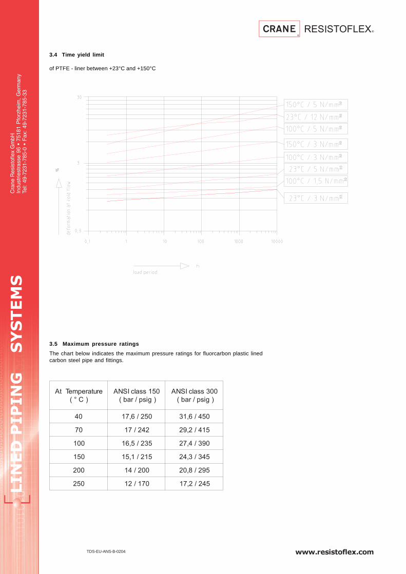
3.4 Time yield limit
of PTFE - liner between +23°C and +150°C
3.5 Maximum pressure ratings
The chart below indicates the maximum pressure ratings for fluorcarbon plastic linedcarbon steel pipe and fittings.
erutarepmeTtA
)C°(
051ssalcISNA
)gisp/rab(
003ssalcISNA
)gisp/rab(
04 052/6,71 054/6,13
07 242/71 514/2,92
001 532/5,61 093/4,72
051 512/1,51 543/3,42
002 002/41 592/8,02
052 071/21 542/2,71

www.resistoflex.com
LIN
ED
P
IP
IN
G S
YS
TE
MS
Cra
ne R
esis
tofle
x G
mbH
Indu
strie
stra
sse
96 •
751
81 P
forz
heim
, G
erm
any
Tel:
49-7
231-
785-
0 •
Fax
: 49
-723
1-78
5-33
4.1 Steel pipe
Steel pipe are either seamless or welded.
They meet the following specifications :
- ASTM A-106, Gr. B- ASTM A-587- ASTM A-53- ASTM A-234 Gr. WPB; SAE 1010-103- St 37.0 = 1.0254- St 37.0 = 1.0254
4.2 Fittings
are assembled from parts acc. to :ASME / ANSI B16.28 / B16.9 for elbowsASME / ANSI B16.9 for tees, reducersDIN 2605 / 2606, Teil 1 for elbowsDIN 2615, Teil 1 for teesDIN 2616, Teil 1 for reducers
or welded from steel pipe. Some of the parts are also machined; for these, thematerials are RSt 37-2 or H II.
4.3 Flanges Variants :
according to ASME / ANSI B16.5 :
- slip on welding- lap joint (with collar or stub end)- lap joint (with lap formed by metal flaring process)- welding neck
The used materials are :
- ASTM A-105- ASTM A-350 Gr. LF 2as well as- RSt 37-2 / 1.0038- H II / 1.0425- C 22.8 / 1.0460
4.4 Screws and Nuts
The quality of screws / nuts being used in the case of assembled parts that arescrewed together in the plant corresponds to DIN 267.For screws applies strength class 4.6 respectively 5.6 in steel as well as A2respectively A4 in alloy steel.For nuts applies strength class 5 in steel as well as A2 respectively A4 in alloy steel.Hexagon socket head screws DIN 912 are only available in class 8.8, 12.9 or A4.Stud bolts DIN 938 will be offered in class 5.8 or A2.
4.5 Options
Earthing studs allow the external earthing of the pipe system and are availabele onValue Series and on Select series. The studs are welded in the middle of the steelfitting or spool with a length of less than 500mm. For longer spools or fittings the stud iswelded at 150 mm behind the flange. The material used for earthing studs is stainlesssteel. The dimensions of the suds are a M6 thread 25mm long.
Vent extenders allow the venting system to perform through the insulation. With ventextenders it is also possible to collect the permeant. Vent extenders are available onValue Series and on Select Sereis. The vent extenders are welded in the middle of thesteel fitting or spool with a length of less than 500mm. For longer spools or fittings thevent extender is welded at 150 mm behind the flange. The standard vent extender hasa 1/8 NPS thread and a outer diameter of 19mm. It is 16mm long and the used material isSt37.
Conductive or antistatic PTFE liner has a black carbon additive that allows for thedissipation of static electricity through the PTFE liner to the metal pipe or fitting wall.Conductive liner is available in the Select Sereis only. Conductive liner thickness are 6%- 8% less than for non-conductive liner. The physical values of conductive liner areapproximately 20% lower than for non conductive liner.
4. Pipe, Fittings and Flanges

LIN
ED
P
IP
IN
G S
YS
TE
MS
Cra
ne R
esis
tofle
x G
mbH
Indu
strie
stra
sse
96 •
751
81 P
forz
heim
, G
erm
any
Tel:
49-7
231-
785-
0 •
Fax
: 49
-723
1-78
5-33
www.resistoflex.comTDS-EU-ANS-C-0204
The tolerances of the lined products observe the specification of ASME / ANSI B16.5.Further details are contained in the single information sheets
The marking of the products is permanent. It is made according to ANSI B16.5. Specialrequests are possible.
With the exception of some red.-flanges, blind-flanges and the solid PTFE parts, all linedpipe and fittings are provided with vent holes. These have diameters mostly from 3to 4 mm. They serve to inspect after production as well as to indicate leaks whenworking.
Depending on service conditions vent hole extensions with an internal thread could bewelded on. This opens the possibility to either compensate for insulation, suck offpermeation or to close them by screws to avoid environmental pollution. If vent holeextensions will be used, one per part is sufficient.
We recommend to keep the vent holes always open. Closed vent holes may causecollapsing of liners, due to permeated gas between lining and housing.
Metal surfaces on the outside of flanged pipe parts are subjected to steel shot blastingSA 2.5 and treated with zinc rich epoxy primer.
Multilayer coatings tend to cracking while fixed at site; we do not recommend them.
All assemblies have their flared gasket faces covered with end plates secured byeither clips or metal bolts. This serves to protect the lining, to keep the flared face downas well as to maintain the interior clean. Parts with injected plastic (PFA) or isostaticallypressed PTFE-gasket faces can be protected by plastic caps.
The final inspection of the finished products occurs in several ways. First of all byvisual control as to clean and good surfaces and subsequently by dimensional controlof length, flange face, threads, check of marking etc. Finally a pressure and tightnesstest according to the shape and dimension is carried out. 100% of all parts are checkedat room temperature as follows :
- straight pipe = 14 x 105 Pa hydraulically or pneumatically
- elbows = 14 x 105 Pa and 35 kV DC
- tees, crosses, instrument tees= 14 x 105 Pa and 35 kV DC
- chemical transfer hoses = 1,5 x nominal pressure
- industrial hoses = 1,5 x working pressure
- others = 35 kV DC or according to agreements
Pressure tests according to ASTM F-423 and F-781 (elevated pressure) are onlycarried out by agreement.
Special checks in warm water bath with outside pressure or vacuum checks underraised temperatures are possible.
5. Tolerances
6. Marking
7. Vent Holes
8. Protective Coating
9. Flange Protectors
10. Final Inspection

www.resistoflex.com
LIN
ED
P
IP
IN
G S
YS
TE
MS
Cra
ne R
esis
tofle
x G
mbH
Indu
strie
stra
sse
96 •
751
81 P
forz
heim
, G
erm
any
Tel:
49-7
231-
785-
0 •
Fax
: 49
-723
1-78
5-33
11.1 General
At the passage of media through pipe parts or flexible hoses static electric chargesmay form. In order to avoid these charges that may lead to spark formation and possiblyto the ignition of gas-air mixtures, the PTFE-lining must allow electrical discharge.RESISTOFLEX GMBH produces upon special request lined pipe parts or fittings andflexible hoses that allow flow of static electricity.
11.2 Values
The values refer only to PTFE powders that are adjusted to be electrically conductive.They apply both to the inside and outside surface and to the passage through the PTFEwall. As soon as the lining comes into contact with the armoured parts, i.e. pipe, hose,etc. , flow of the charge through these occurs; this discharge takes place throughmetal parts and is therefore smaller than 106 Ohm.
RESISTOFLEX GmbH produces PTFE linings having surfaceresistivities in the range between 104 and 108 Ohm. This isaccording to the “Directions to avoid ignition danger as a result of electrostaticcharges” of the trade associations, committee of experts for chemistry, ZH 1/200.
Measuring is being carried out according to DIN 53 482 and / or ASTM D257. Thefollowing definitions apply :
1. “Volume resistivity”
RA = 1 x 10⁶ bis 5 x 10⁸ (Ω x cm2) referred to an electrode surface ofdiameter 24,2 or diameter 49,5 mm according to 5 or 20 cm2 .
2. “Volume resistance “
RD in (Ω ) that is multiplied by the electrode surface .
RD = 1 x 10⁶ bis 1 x 10⁸ (Ω )‘
3. “surface resistance” RO is being measured. It gives information on the insulationcondition on the surface of a material.
R0 = 1 x 10⁶ bis 5 x 10⁸ (Ω )
11.3 Volume and surface resistivities
The Volume and surface resistivities acc. to DIN 53 428 are within 104 and 106 Ohm forPTFE - granular resin and within 106 and 108 Ohm for PTFE - fine powder resin,depending on the kind of product.
Electrically conductive PTFE - linings normally yield wallthicknesses which are 6 % to8 % thinner than white ones.
The physical values are also reduced to a level of approx. 20 % below.
11.4 We furthermore would like to inform you, that for some liquids it might occur, that itabsorbs the carbon black off the PTFE and could be contaminated.
11. Surface resistivityon PTFE-Linings

LIN
ED
P
IP
IN
G S
YS
TE
MS
Cra
ne R
esis
tofle
x G
mbH
Indu
strie
stra
sse
96 •
751
81 P
forz
heim
, G
erm
any
Tel:
49-7
231-
785-
0 •
Fax
: 49
-723
1-78
5-33
www.resistoflex.comTDS-EU-ANS-D-0204
Lined products must not be welded, brazed or torch-cut since this may damage thelining.
For shipment all flanges are protected by covers to prevent damaging during transportand storage. These covers should only be removed shortly before installation. Ifdismantled for inspection they should be replaced immediately.
It is not necessary to use gaskets between the PTFE sealing faces. If, however, flaresare connected to sealing faces of other materials, such as glass, ceramics, carbon, ormetal, and where the flares may not be parallel, it is recommended that an additionalPTFE gasket be employed. This gasket should be 5 mm thick. It can absorbunevenness.
Excessive bolt tightening during assembly can deform the sealing face. To avoid this,the following bolt torques should not be exceeded.
See table below for allowed torques.
12.1 Bolt torques
Bolt torques of the flange screws to ANSI B16.5 for Class 150 and Class 300 areshown in the table below.
These torque values are valid for lightly oiled A 193 B7 bolts and A 194 2H nuts andevtl. washers. Corroded threads may increase the torque values ineffective or evendouble them.
Tighten the flange bolts with a torque wrench, using a “crisscross” pattern thatalternately tightens the bolts located 180 ° apart. Using this pattern, tighten the bolts in20 % increments of the final bolt torque until 80 % of the final bolt torque has beenachieved. For tightening to the final torque values, tighten bolts sequently clockwiseonce around the flange. This will help ensure that the bolts are evenly stressed.
12. Installation andMaintenanceInstructions forLined Pipe,Fittings, TransferHoses andExpansion Joints
051ssalC5.61BISNA 003ssalC5.61BISNA
noisnemiD stlobfo.on euqrottlob stlobfo.on euqrottlob
x + %52 + %52 x + %52 + %52
SPN daerht sbl-tf mN daerht sbl-tf mN
"2/1 "2/1x4 51-01 12-41 "2/1x4 81-21 62-71
"4/3 "2/1x4 51-01 12-41 "8/5x4 81-21 62-71
"1 "2/1x4 71-11 32-51 "8/5x4 02-31 72-81
"2/11 "2/1x4 83-52 35-53 "4/3x4 75-83 08-35
"2 "8/5x4 08-25 011-37 "8/5x8 04-62 45-63
"2/12 "8/5x4 501-86 541-59 "4/3x8 06-04 48-65
"3 "8/5x4 521-28 371-511 "4/3x8 57-05 501-07
"4 "8/5x8 38-55 611-77 "4/3x8 89-56 731-19
"5 "4/3x8 521-28 371-511 "4/3x8 541-69 302-531
"6 "4/3x8 051-001 012-041 "4/3x21 001-66 041-39
"8 "4/3x8 502-531 582-091 "8/7x21 851-501 122-741
"01 "8/7x21 091-521 362-571 "1x61 261-801 822-251
"21 "8/7x21 532-551 623-712 "8/11x61 812-541 503-302
"41 "1x21 032-251 513-012 "8/11x02 812-541 503-302
"61 "1x61 512-341 003-891 "4/11x02 092-291 004-662
"81 "8/11x61 513-012 534-092 "4/11x42 392-591 014-372
"02 "8/11x02 582-091 593-262 "4/11x42 033-022 264-803
"42 "4/11x02 533-122 854-503 "2/11x42 084-023 276-844
www.resistoflex.com
LIN
ED
P
IP
IN
G S
YS
TE
MS
Cra
ne R
esis
tofle
x G
mbH
Indu
strie
stra
sse
96 •
751
81 P
forz
heim
, G
erm
any
Tel:
49-7
231-
785-
0 •
Fax
: 49
-723
1-78
5-33
A retorque should be applied a minimum of 24 hours after the initial torque orafter the first thermal cycle. This allows for seating of the plastic and forrelaxation of the bolts. If the system is to perform at elevated temperatures, it isrecommended that hot water be circulated at the maximum operatingtemperature of the process if possible for a minimum of 24 h. This allows forthe pipe system to experience one thermal cycle. After cool-down, retorquingof the system should be done. Torquing should only be done on the system inthe ambient, cooled state, never while the process is at elevated temperature orexcessive force could be applied to the plastic faces.
Retorque should be done annually thereafter especially if the process lineexperiences elevated temperatures or extreme ambient temperature situations.Frequency of retorque depends on application. Vibration, bolt strenth or numberof thermocycles are important. Continous processes need less retorque.Cold flow of flare material is shown under 3.3 of this specification.
All lined products have small vent holes. It is important that these are not beblocked by insulation or plugged by paint as this may cause the lining tocollapse. These vent holes also serve as early warning leakage indicators.Thenumber of vent holes may be reduced if necessary. Those which remain couldbe provided with screwed couplings to either closed with nipples or connectedto a vacuum pump.
To avoid damage to the sealing faces, pipes and fittings should only bedismantled below +40°C / +104°F.
If a flange connection leaks even though all bolts are tight, DO NOT TIGHTENUP ANY MORE. Never exceed the above mentioned bolt torques.Loosen the bolts opposite the leak and tighten up the other side. If leakagepersists, the sealing faces should be inspected for grooves or chips. Groovesor nicks not deeper than approx. 15% of the flare thickness can be removedwith fine-grained abrasive paper.
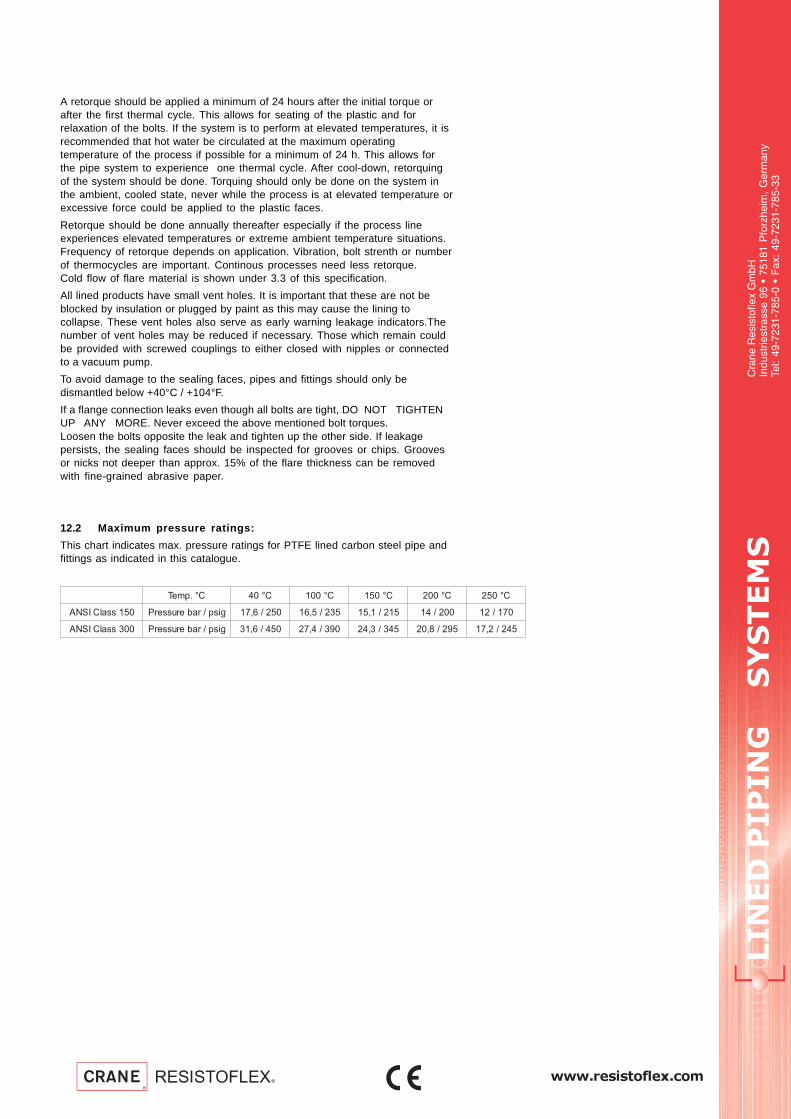
12.2 Maximum pressure ratings:
This chart indicates max. pressure ratings for PTFE lined carbon steel pipe andfittings as indicated in this catalogue.
C°.pmeT C°04 C°001 C°051 C°002 C°052
051ssalCISNA gisp/raberusserP 052/6,71 532/5,61 512/1,51 002/41 071/21
003ssalCISNA gisp/raberusserP 054/6,13 093/4,72 543/3,42 592/8,02 542/2,71

LIN
ED
P
IP
IN
G S
YS
TE
MS
Cra
ne R
esis
tofle
x G
mbH
Indu
strie
stra
sse
96 •
751
81 P
forz
heim
, G
erm
any
Tel:
49-7
231-
785-
0 •
Fax
: 49
-723
1-78
5-33
www.resistoflex.comTDS-EU-ANS-E-0204
13. Permeation13.1 Permeation RatingsPermeation on different kinds of fluoropolymer linings;comparison.
The test conditions are as follows:
- surface of samples = 50 cm2
- test medium = Helium
- test pressure ∆p = 2 bar
13.2 Permeation, migration of molecules through the lining wall
Diffusion is a spontaneous transport of medium caused by thermodynamic forces tocompensate for concentration differences. The media migrates in the direction ofdecreasing concentration.Of practical importance is the permeation through finite wall thicknesses with measuredvalues for judgement.How now does the permation of a molecule through a plastic wall happen and whichare the most important parameters?A molecule inside the tube wall exerts almost elastic vibrations against it. With it energymust be supplied to overcome the linkage forces in the plastic or to move through so-called free spaces (no voids) . PTFE is a hypocrystalline substance and the so-calledfree spaces are to be found in the amorphous part. Crystalline zones are notpenetrated.
A series of influences causes individually or together the permeated quantity.It is presumed that both from liquid media and from gases only the gases permeate. Themoving forces with it are the concentration or the partial pressure. In the case ofsubstance mixtures both single components and their interactives may migrate. Littlemolecules get easier through so-called free spaces than big ones. Chain molecules aswell permeate easier than branched ones, since their cross-sectional area is smaller.A temperature increase supplies energy; this increases vibrations in the wall and in themedia. Thus the activity of the molecules increases, the wall expands and possibly theamorphous part of the wall PTFE increases and as a result more molecules movequicker through.We get into a limit area when a media has a similar or equal polarity as the lining. Thenthe liquid may partially dissolve in the wall; it is then spoken of a swelling. With it thespace between the macromolecules of the wall increases, that is more and greaterfree spaces develop. All molecules move then quicker through the wall even if only onegenerates the swelling. The thicker the lining is, the smaller is the permeation.High crystallinity reduces permeation. Greatest caution is anyhow advisable here, sinceas manufacturers we always aspire to an optimum between permeation and durabilitywith regards to crackings in the PTFE; high crystallinity reduces flexibility and increasesdrastically the risk of fracture. FLUOROFLEX products always guarantee durability, lowpermeation values and operational reliability.
lairetaM elpmaSfossenkcihT erutarepmeT tseTfoemiT noitaemreP
mm F°/C° h
mliF-AFP 3,277/52 283 3,5.ac
581/58 48 22.ac
maR-EFTP 477/52 283 3,3.ac
581/58 48 03.ac
talunarG-EFTP 477/52 283 2,1-4,0
581/58 48 7-4,1
etsaP-EFTP 477/52 283 1-3,0
581/58 48 5-5,1
dm3
m2 x 24h x bar

www.resistoflex.com
LIN
ED
P
IP
IN
G S
YS
TE
MS
Cra
ne R
esis
tofle
x G
mbH
Indu
strie
stra
sse
96 •
751
81 P
forz
heim
, G
erm
any
Tel:
49-7
231-
785-
0 •
Fax
: 49
-723
1-78
5-33
In general PTFE is chemically inert. We therefore differentiate between chemicalreaction and physical behaviour. That is why in the following we deal with the physicalinteraction between plastic and contacting media.
Submicroscopic little spaces between the polymer molecules make it for somesubstances, as e. g. water vapor, monomeres etc., possible to diffuse into the PTFE. Bythis the spontaneous media transport caused by pressure and temperature is meant.The medium moves in the direction of decreasing concentration.Absorption means here that a liquid diffuses into the PTFE and that the quantityincreases with increasing pressure and increasing temperature.If a lined tubing part is subjected to cyclic pressure and temperature loads, so that theliquid entrapped in the plastic wall evaporates or condenses, then the resistance of theplastic may be reduced at several points. This originates bubbles that in the course oftime develop into so-called blisters. The PTFE there suffers a locally limited delamination.
FLUOROFLEX-PTFE linings are brought into an optimal condition. Only raw materialhaving on one hand a sufficient flexibility and on the other a relatively high share incrystalline PTFE are being used. The situation is additionally aggravated by the greatoperative temperature range of PTFE and the thermal fluctuation originating with itbetween operation and standstill. It is presumed that owing to the pressure drop vapourpenetrates in the PTFE, and since there prevails a great temperature drop the vapourcondenses in the wall. During cyclic operation, that is stop and restart, the entrappedcondensation quantities are being expanded with rising temperature, their volumeincreases and the plastic is being locally laminated.
Depending on this condition the formation of bubbles or blistering proceeds. Thisanyhow leads not at all or only after a comparatively long time to the total failure oroutage of parts, since blisters mostly lie in the inner third of the wall, that is maintainedin its function as separation layer.How can we reduce this phenomenon? Since mostly the process condition cannot bechanged, an insulation of the tubing parts usually clearly improves the situation or evenavoids these blisters completely, the insulation of the flange area or other metalsuspensions being there particularly important. The insulation avoids the greattemperature drop and thus the condensation that is later expansion.
A qualifying test for PTFE is therefore also the so-called vapour-cold water testaccording to ASTM F-423.
Papers treating this subject are:
- Du Pont, reprint of the “Journal of Teflon” Nr. 125-D-2; A-62722-2.
- Du Pont, Teflon/Tefzel, protection against corrosion in chemistry H-11959-2.
- ASTM F-423
- NBS Voluntary Product Standard PS 33-70 des US Department of Commerce
All data shown in this catalogue according to our best knowledge but does notconstitute any form of guarantee. Recommendations for use are only advisory.They do not release the user from his obligation to prior check the delivered productsconcerning their safety and readiness for use.
14. PTFE AbsorptionBehaviour inChemicalAplication
15. GeneralInformation
LIN
ED
P
IP
IN
G S
YS
TE
MS
Cra
ne R
esis
tofle
x G
mbH
Indu
strie
stra
sse
96 •
751
81 P
forz
heim
, G
erm
any
Tel:
49-7
231-
785-
0 •
Fax
: 49
-723
1-78
5-33
www.resistoflex.com
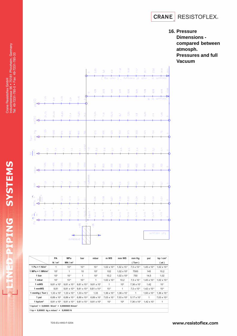
AP aPM rab rabm SWm SWmm gHmm isp mc/pk 2
m/N 2 m/NM 2 )rroT( )ta(
m/N1=aP1 2 1 01 6- 01 5- 01 2- 01x20,1 4- 01x20,1 1- 01x5,7 3- 01x54,1 4- 01x20,1 5-
m/NM1=aPM1 2 01 6 1 01 01 4 201 01x20,1 5 0057 541 2,01
rab1 01 5 01 1- 1 01 3 2,01 01x20,1 4 057 5,41 20,1
rabm1 01 2 01 4- 01 3- 1 01x20,1 2- 2,01 01x5,7 1- 01x54,1 2- 01x20,1 3-
SWm1 01x18,9 3 01x18,9 3- 01x18,9 2- 01x18,9 1 1 01 3 01x63,7 1 24,1 01 1-
SWmm1 18,9 01x18,9 6- 01x18,9 5- 01x18,9 2- 01 3- 1 01x5,7 2- 01x24,1 3- 01 4-
)rroT(gHmm1 01x33,1 2 01x33,1 4- 01x33,1 3- 33,1 01x63,1 2- 01x63,1 1 1 01x39,1 2- 01x63,1 3-
isp1 01x98,6 3 01x98,6 3- 01x98,6 2- 01x98,6 1 01x30,7 1- 01x30,7 2 01x71,5 1 1 01x30,7 2-
mc/pk1 2 01x18,9 4 01x18,9 2- 01x18,9 1- 01x18,9 2 01 1 01 4 01x63,7 2 01x24,1 1 1
mc/pk1 2 mc/N56608,9= 2 mm/N5660890,0= 2
ces/mxgk56608,9=pk1 2 N56608,9=
TDS-EU-ANS-F-0204
16. PressureDimensions -compared betweenatmosph.Pressures and fullVacuum


LIN
ED
P
IP
IN
G S
YS
TE
MS
Cra
ne R
esis
tofle
x G
mbH
Indu
strie
stra
sse
96 •
751
81 P
forz
heim
, G
erm
any
Tel:
49-7
231-
785-
0 •
Fax
: 49
-723
1-78
5-33
www.resistoflex.com
PTFE Lined Pipe Spools(ANSI)
ASTM F1545CE, PED Cat. III (>1”)TEFLON® by DuPont
Form No. TDS-EU-ANS-PFT-0804
* Class 300 and Value Series are subject to CE approval† These options also available in Value SeriesSome Select Series and Value Series items use components not listed in ASTM F1545.
eulaV
*seireSseireStceleS
LxL LxFtceffayamnoitcelesnoitpO.smetikcotsnoelbaliavatonwolebsnoitpO
.yrevileddnaecirprofyrotcaftlusnoC.emitdaelgnirutcafunam051ssalC 051ssalC
"2/1
"4/3
"1
"5.1
"2
"3
"4
"6
"8
"01
"21
"41
"61
"81
"02
"42
Sta
inle
ss S
teel
Hou
sing
Con
duct
ive
Line
r
Hea
vy D
uty
Line
r
Spe
cial
Pai
nt†
Ear
thin
g S
tuds
†
Ven
t Ext
ende
rs†
Cla
ss 3
00 F
lang
es*
Nom
inal
Siz
e
)skeeW2-1(emiTdaeL&ecirPtseB 032tamuucaVlluF OC
)skeeW6-4(emiTdaeLregnoL .pmeTdetavelEtaecnatsiseRmuucaVdecudeR
tseuqeRnopUyrevileDdnaecirP detaRmuucaV-noN

www.resistoflex.com
LIN
ED
P
IP
IN
G S
YS
TE
MS
Cra
ne R
esis
tofle
x G
mbH
Indu
strie
stra
sse
96 •
751
81 P
forz
heim
, G
erm
any
Tel:
49-7
231-
785-
0 •
Fax
: 49
-723
1-78
5-33
PTFE Lined Pipe Spools (ANSI)
Welded Steel
Notes:
1.) Drawing shows typical Value Series construction
2.) Vent holes are located on each end of pipe.
.
Dimensional Data per Class 150
Part Number System
Finished
RO
B -
valu
e se
reis
RO
F -
sele
ct s
erie
s
15 - ANSI 15030 - ANSI 300
FF - Fixed/FixedFL - Fixed/LooseLL - Loose/Loose
W - WhiteE - Anti-Static
Factory Defined
0XX - Standard052 - Earthing Stud054 - Vent Boss070 - Stainless Steel
200 -8”
250 -10”
300 -12”
350 -14”
400 -16”
450 -18”
500 -20”
600 -24”
015 - 1/2”
020 - 3/4”
025 - 1”
040 - 1 1/2”
050 - 2”
080 - 3”
100 - 4”
150 - 6”
1 - Value0 - Select
Diameter Pressure FlangesType Liner Resin Type OptionsSeries
1 250 15 W FF 0XXXX 0ROB
eziS
seireSeulaV seireStceleS
C
)mm(
)gk.ac(thgieW
L.niM
)mm(
L.xaM
)mm(
S
+ %01
)mm(
L.niM
)mm(
L.xaM
)mm(
S
+ %01
)mm(
reP
reteM
owT
segnalF
"2/1 511 0006 5.2 53 2.1 5.1
"4/3 031 0005 3 34 6.1 2
"1 023 0006 5,3 041 0006 5,3 15 5.2 5.2
"5.1 023 0006 4 051 0006 4 37 5.4 2.4
"2 043 0006 4 551 0006 4 29 8.5 5.5
"3 053 0006 4 581 0006 4 721 01 3.8
"4 063 0006 4 002 0006 4 751 41 9.9
"6 083 0006 7 532 0006 7 612 5.32 61
"8 093 0006 52.6 562 0006 52.6 072 93 32
"01 072 0004 57.6 423 5.55 13
"21 582 0053 8 183 47 93
"41 023 0003 9 214 58 25
"61 523 0052 01 074 201 76
"81 043 0053 5.6 435 031 58
"02 563 0052 5.6 585 551 09
"42 573 0001 5.4 296 402 611

LIN
ED
P
IP
IN
G S
YS
TE
MS
Cra
ne R
esis
tofle
x G
mbH
Indu
strie
stra
sse
96 •
751
81 P
forz
heim
, G
erm
any
Tel:
49-7
231-
785-
0 •
Fax
: 49
-723
1-78
5-33
www.resistoflex.com
PTFE Lined 90 Degree Elbow(ANSI)
ASTM F1545
CE, PED Cat. III (>1”)
TEFLON® by DuPont
)skeeW2-1(emiTdaeL&ecirPtseB 032tamuucaVlluF OC
)skeeW6-4(emiTdaeLregnoL .pmeTdetavelEtaecnatsiseRmuucaVdecudeR
tseuqeRnopUyrevileDdnaecirP detaRmuucaV-noN
segnalFdexiF-ydoBnorIelitcuD
Form No. TDS-EU-ANS-L9T-0104
seireSeulaV seireStceleS
LxL FxF noitpO.smetikcotsnoelbaliavatonwolebsnoitpO
.emitdaelgnirutcafunamtceffayamnoitceles
.yrevileddnaecirprofyrotcaftlusnoC051ssalC 051ssalC
"2/1
"4/3
"1
"5.1
"2
"3
"4
"6
"8
"01
"21
"41
"61
"81
"02
"42
Nom
inal
Dia
met
er
Cla
ss 3
00 F
lgs.
*(C
lass
150
Dim
s)
Loos
e F
lang
es
Spe
cial
Ang
le
Sta
inle
ss S
teel
Hou
sing
Con
duct
ive
Line
r
Cla
ss 3
00 F
lgs.
*(C
lass
300
Dim
s)
Hea
vy D
uty
Line
r
Spe
cial
Pai
nt†
Ear
thin
g S
tuds
†
Ven
t Ext
ende
rs†
* Class 300 subject to CE approval
† These options also available in Value Series24” 90 Ell is made of three partsValue Series conforms to ASTM F1545. Some Select Series items use components not listed in ASTM F1545.

www.resistoflex.com
LIN
ED
P
IP
IN
G S
YS
TE
MS
Cra
ne R
esis
tofle
x G
mbH
Indu
strie
stra
sse
96 •
751
81 P
forz
heim
, G
erm
any
Tel:
49-7
231-
785-
0 •
Fax
: 49
-723
1-78
5-33
Part Number System
Finished90 Deg.Elbow
15 - ANSI 15030 - ANSI 300
FF - Fixed/FixedFL - Fixed/LooseLL - Loose/Loose
W - WhiteE - Anti-Static
Factory Defined
0XX - Standard052 - Earthing Stud054 - Vent Boss070 - Stainless Steel
200 - 8”
250 - 10”
300 - 12”
350 - 14”
400 - 16”
450 - 18”
500 - 20”
600 - 24”
015 -1/2”
020 -3/4”
025 -1”
040 -1 1/2”
050 -2”
080 -3”
100 -4”
150 -6”
1 - Value0 - Select
Diameter Pressure FlangesFittingType Liner Resin Type OptionsSeries
1 B90 250 15 W FF 0XXXX 0
PTFE Lined 90 Deg. Elbow (ANSI)
Welded Steel
Dimensional Data per Class 150
Notes:
1.) Drawing shows typical Value Series construction
2.) Vent holes are located on side of elbow in center.
3.) Weld buttons are located approximately 25mm behind
each flange.
eziS )mm(L )mm(C
S + )mm(%01
thgieW
)gk.ac(eulaV
seireS
tceleS
seireS
"2/1 57 53 3 5.1
"4/3 98 34 3 1.2
"1 98 15 5.3 3 7.2
"5.1 201 37 5.3 4 4
"2 411 29 5.3 4 4.6
"3 041 721 5.3 5.4 21
"4 561 851 5.7 5.4 91
"6 302 612 5.9 8 63
"8 922 072 31 9 75
"01 972 423 5.41 31 28
"21 503 183 5.61 01 111
"41 006 214 21 561
"61 016 074 31 291
"81 376 435 31 532
"02 637 585 31 082
"42 468 296 5.6 593

LIN
ED
P
IP
IN
G S
YS
TE
MS
Cra
ne R
esis
tofle
x G
mbH
Indu
strie
stra
sse
96 •
751
81 P
forz
heim
, G
erm
any
Tel:
49-7
231-
785-
0 •
Fax
: 49
-723
1-78
5-33
www.resistoflex.com
PTFE Lined 45 Degree Elbow(ANSI)
ASTM F1545
CE, PED Cat. III (>1”)
TEFLON® by DuPont
Form No. TDS-EU-ANS-L5T-0104
seireSeulaV seireStceleS
LxL FxF noitpO.smetikcotsnoelbaliavatonwolebsnoitpO
.emitdaelgnirutcafunamtceffayamnoitceles
.yrevileddnaecirprofyrotcaftlusnoC051ssalC 051ssalC
"2/1
"4/3
"1
"5.1
"2
"3
"4
"6
"8
"01
"21
"41
"61
"81
"02
Nom
inal
Dia
met
er
Cla
ss 3
00 F
lgs*
(Cla
ss 1
50 D
ims)
Loos
e F
lang
es
Spe
cial
Ang
le
Sta
inle
ss S
teel
Hou
sing
Con
duct
ive
Line
r
Cla
ss 3
00 F
lgs*
(Cla
ss 3
00 D
ims)
Sta
ndar
dH
eavy
Dut
y Li
ner
Spe
cial
Pai
nt†
Ear
thin
g S
tuds
†
Ven
t Ext
ende
rs†
(F X F)
(F X F)
* Class 300 subject to CE approval† These options also available in Value Series
Value Series conforms to ASTM F1545. Some Select Series items use components not listed in ASTM F1545.
)skeeW2-1(emiTdaeL&ecirPtseB 032tamuucaVlluF OC
)skeeW6-4(emiTdaeLregnoL .pmeTdetavelEtaecnatsiseRmuucaVdecudeR
tseuqeRnopUyrevileDdnaecirP detaRmuucaV-noN
segnalFdexiF-ydoBnorIelitcuD

www.resistoflex.com
LIN
ED
P
IP
IN
G S
YS
TE
MS
Cra
ne R
esis
tofle
x G
mbH
Indu
strie
stra
sse
96 •
751
81 P
forz
heim
, G
erm
any
Tel:
49-7
231-
785-
0 •
Fax
: 49
-723
1-78
5-33
PTFE Lined 45 Deg. Elbow (ANSI)
Welded Steel
Dimensional Data per Class 150
Notes:
1.) Drawing shows typical Value Series
construction
2.) Vent holes are located on side of elbow
in center.
3.) Weld buttons are located approximately
25mm behind each flange.
Part Number System
Finished45 Deg.Elbow
15 - ANSI 15030 - ANSI 300
FF - Fixed/FixedFL - Fixed/LooseLL - Loose/Loose
W - WhiteE - Anti-Static
Factory Defined
0XX - Standard052 - Earthing Stud054 - Vent Boss070 - Stainless Steel
200 -8”
250 -10”
300 -12”
350 -14”
400 -16”
450 -18”
500 -20”
015 - 1/2”
020 - 3/4”
025 - 1”
040 - 1 1/2”
050 - 2”
080 - 3”
100 - 4”
150 - 6”
1 - Value0 - Select
Diameter Pressure FlangesFittingType Liner Resin Type OptionsSeries
1 B45 250 15 W FF 0XXXX 0
* 1/2” - 3” Select Series loose flange requires longer than standard “L” dimension.
Value Series “L” dimension is ANSI Class 150 standard for fixed or loose flange.
** L dimension extended
eziS
)mm(L
C
)mm(
S + )mm(%01
thgieW
)gk.ac(
seireSeulaV seireStceleS
dexiF
egnalF
esooL
egnalF
dexiF
egnalF
esooL
egnalF
eulaV
seireS
tceleS
seireS
"2/1 54 *06 53 3 7.1
"4/3 54 *06 34 3 2
"1 54 54 *06 15 5.3 3 3
"5.1 75 75 *57 37 5.3 4 6
"2 46 46 *08 29 5.3 4 9
"3 67 67 *09 721 5.3 5.4 51
"4 201 201 751 5.7 5.4 02
"6 721 721 612 5.9 8 33
"8 041 041 072 8 9 45
"01 561 561 423 31 31 57
"21 091 091 183 5.61 01 011
"41 **582 214 21 521
"61 **523 074 31 541
"81 **503 435 31 581
"02 **093 585 31 012

LIN
ED
P
IP
IN
G S
YS
TE
MS
Cra
ne R
esis
tofle
x G
mbH
Indu
strie
stra
sse
96 •
751
81 P
forz
heim
, G
erm
any
Tel:
49-7
231-
785-
0 •
Fax
: 49
-723
1-78
5-33
www.resistoflex.com
PTFE Lined Equal Tee (ANSI)
ASTM F1545CE, PED Cat. III (>1”)TEFLON® by DuPont
Form No. TDS-EU-ANS-TET-0104
seireSeulaV seireStceleS
LxLxL FxFxF noitpO.smetikcotsnoelbaliavatonwolebsnoitpO
.emitdaelgnirutcafunamtceffayamnoitceles
.yrevileddnaecirprofyrotcaftlusnoC051ssalC 051ssalC
"2/1
"4/3
"1
"5.1
"2
"3
"4
"6
"8
"01
"21
"41
"61
"81
"02
"42
Nom
inal
Siz
e
Cla
ss 3
00 F
lgs*
(Cla
ss 1
50 D
ims)
Sho
rt S
tack
(D
uctil
e Ir
on)
Loos
e F
lang
es
PFA
-Lin
ed
Sta
inle
ss S
teel
Hou
sing
Con
duct
ive
Line
r
Hea
vy D
uty
Line
r
Spe
cial
Pai
nt†
Ear
thin
g S
tuds
†
Ven
t Ext
ende
rs†
Sta
ndar
d2-
Pc
Bod
y C
onst
ruct
ion
Sta
ndar
d
* Class 300 subject to CE approval† These options also available in Value Series
Value Series conforms to ASTM F1545. Some Select Series items use components not listed in ASTM F1545.
)skeeW2-1(emiTdaeL&ecirPtseB 032tamuucaVlluF OC
)skeeW6-4(emiTdaeLregnoL .pmeTdetavelEtaecnatsiseRmuucaVdecudeR
tseuqeRnopUyrevileDdnaecirP detaRmuucaV-noN

www.resistoflex.com
LIN
ED
P
IP
IN
G S
YS
TE
MS
Cra
ne R
esis
tofle
x G
mbH
Indu
strie
stra
sse
96 •
751
81 P
forz
heim
, G
erm
any
Tel:
49-7
231-
785-
0 •
Fax
: 49
-723
1-78
5-33
PTFE Lined Equal Tee (ANSI)
Welded Steel
Notes:
1.) Drawing shows typical Value Series construction
2.) Vent holes are located on side of tee in center.
3.) Weld buttons are located approximately 25mm behind
each flange.
Dimensional Data per Class 150
Part Number System
FinishedEqualTee
15 - ANSI 15030 - ANSI 300
FF - Fixed/FixedFL - Fixed/LooseLL - Loose/Loose
W - WhiteE - Anti-Static
Factory Defined
0XX - Standard052 - Earthing Stud054 - Vent Boss070 - Stainless Steel
200 -8”
250 -10”
300 -12”
350 -14”
400 -16”
450 -18”
500 -20”
600 -24”
015 - 1/2”
020 - 3/4”
025 - 1”
040 - 1 1/2”
050 - 2”
080 - 3”
100 - 4”
150 - 6”
1 - Value0 - Select
Diameter Pressure FlangesFittingType Liner Resin Type OptionsSeries
1 TEE 250 15 W FF 0XXXX 0
eziS )mm(L )mm(C
S + )mm(%01
thgieW
)gk.ac(eulaV
seireS
tceleS
seireS
"2/1 56 73 4 5.2
"4/3 57 54 5.4 2.3
"1 98 15 5.3 5.3 5.5
"5.1 201 37 5.3 5.4 5.9
"2 411 29 5.4 5.4 5.11
"3 041 721 6 5 5.91
"4 561 751 6 6 42
"6 302 612 5.8 7 54
"8 922 072 5.11 01 27
"01 082 423 31 31 021
"21 503 183 5.41 31 061
"41 653 214 5.6 213
"61 183 074 5.6 573
"81 914 435 5.6 004
"02 754 585 5.6 024
"42 005 296 5.4 085

LIN
ED
P
IP
IN
G S
YS
TE
MS
Cra
ne R
esis
tofle
x G
mbH
Indu
strie
stra
sse
96 •
751
81 P
forz
heim
, G
erm
any
Tel:
49-7
231-
785-
0 •
Fax
: 49
-723
1-78
5-33
www.resistoflex.com
PTFE Lined Reducing Tee(ANSI)
ASTM F1545CE, PED Cat. III (>1”)TEFLON® by DuPont
* Class 300 subject to CE approval† These options also available in Value Series
)skeeW2-1(emiTdaeL&ecirPtseB 032tamuucaVlluF OC
)skeeW6-4(emiTdaeLregnoL erutarepmeTdetavelEtaecnatsiseRmuucaVdecudeR
tseuqeRnopUyrevileDdnaecirP detaRmuucaV-noN
Form No. TDS-EU-ANS-TRT-1-6-0104
Value Series conforms to ASTM F1545. Some SelectSeries items use components not listed in ASTM F1545.
seireSeulaV seireStceleS
LxLxL FxFxF noitpO.smetikcotsnoelbaliavatonwolebsnoitpO
.emitdaelgnirutcafunamtceffayamnoitceles
.yrevileddnaecirprofyrotcaftlusnoC051ssalC 051ssalC
"1
"2/1
"4/3
"5.1
"2/1
"4/3
"1
"2
"1
"5.1
"3
"1
"5.1
"2
"4
"1
"5.1
"2
"3
"6
"1
"5.1
"2
"3
"4
Maj
or S
ize
Cla
ss 3
00 F
lgs*
(Cla
ss 1
50 D
ims)
Loos
e F
lang
es
PFA
-Lin
ed
Sta
inle
ss S
teel
Hou
sing
Con
duct
ive
Line
r
Hea
vy D
uty
Line
r
Spe
cial
Pai
nt†
Ear
thin
g S
tuds
†
Ven
t Ext
ende
rs†
Sta
ndar
d
Min
or S
ize
Sta
ndar
d
1” - 6”

www.resistoflex.com
LIN
ED
P
IP
IN
G S
YS
TE
MS
Cra
ne R
esis
tofle
x G
mbH
Indu
strie
stra
sse
96 •
751
81 P
forz
heim
, G
erm
any
Tel:
49-7
231-
785-
0 •
Fax
: 49
-723
1-78
5-33
PTFE Lined Reducing Tee (ANSI)
Welded Steel
1” - 6”
Notes:
1.) Drawing shows typical Value Series construction
2.) Vent holes are located on side of tee in center.
3.) Weld buttons are located approximately 25mm
behind each flange.
Dimensional Data per Class 150
For loose stack flange on 6” Select Series, LA = L + 30mm
Part Number System
FinishedReducing
Tee15 - ANSI 15030 - ANSI 300
FF - Fixed/FixedFL - Fixed/LooseLL - Loose/Loose
W - WhiteE - Anti-Static
Factory Defined
0XX - Standard052 - Earthing Stud054 - Vent Boss070 - Stainless Steel
1 - Value0 - Select
Diameter Pressure FlangesFittingType Liner Resin Type OptionsSeries
1 RTE XXX 15 W FF 0XXXX 0
Consult Factory
rojaM
eziS
roniM
eziS
L/LA
)mm(
C1
C2
S + )mm(%01
thgieW
)gK.ac(
eulaV
seireS
tceleS
seireS
S1
S2
S1
S2
"1"2/1
98 1573
4 47.3
"4/3 54 9.3
"5.1
"2/1
201 37
734 4
3.5
"4/3 54 5.5
"1 15 4 4.3 5.4 5.3 8
"2"1
411 2915
54.3
5.45.3 9.8
"5.1 37 4 5.4 5.01
"3
"1
041 721
15
6
4.3
5
5.3 61
"5.1 37 4 5.4 71
"2 29 5.4 5.4 5.71
"4
"1
561 851
15
6
4
6
5.3 91
"5.1 37 4 5.4 12
"2 29 5.4 5.4 22
"3 721 6 5 42
"6
"1
302 612
15
7
5.3 5.82
5.1 37 5.4 13
"2 29
9
5.4 5.4 23
"3 721 6 5 43
"4 851 9 6 4.53

LIN
ED
P
IP
IN
G S
YS
TE
MS
Cra
ne R
esis
tofle
x G
mbH
Indu
strie
stra
sse
96 •
751
81 P
forz
heim
, G
erm
any
Tel:
49-7
231-
785-
0 •
Fax
: 49
-723
1-78
5-33
www.resistoflex.com
PTFE Lined Reducing Tee(ANSI)
ASTM F1545CE, PED Cat. III (>1”)TEFLON® by DuPont
8” - 14”
Sta
ndar
d
)skeeW2-1(emiTdaeL&ecirPtseB 032tamuucaVlluF OC
)skeeW6-4(emiTdaeLregnoL erutarepmeTdetavelEtaecnatsiseRmuucaVdecudeR
tseuqeRnopUyrevileDdnaecirP detaRmuucaV-noN
Form No. TDS-EU-ANS-TRT-8-14-0104
seireSeulaV seireStceleS
LxLxL FxFxF noitpO.smetikcotsnoelbaliavatonwolebsnoitpO
.emitdaelgnirutcafunamtceffayamnoitceles
.yrevileddnaecirprofyrotcaftlusnoC051ssalC 051ssalC
"8
"2
"3
"4
"6
"01
"2
"4
"6
"8
"21
"2
"4
"6
"8
"01
"41
"2
"4
"8
Sta
ndar
d
Maj
or S
ize
Cla
ss 3
00 F
lgs*
(Cla
ss 1
50 D
ims)
Loos
e F
lang
es
2-P
c B
ody
Con
stru
ctio
n
Sta
inle
ss S
teel
Hou
sing
Con
duct
ive
Line
r
Hea
vy D
uty
Line
r
Spe
cial
Pai
nt†
Ear
thin
g S
tuds
†
Ven
t Ext
ende
rs†
Min
or S
ize
* Class 300 subject to CE approval† These options also available in Value Series
Value Series conforms to ASTM F1545. Some Select Series items use components not listed in ASTM F1545.

www.resistoflex.com
LIN
ED
P
IP
IN
G S
YS
TE
MS
Cra
ne R
esis
tofle
x G
mbH
Indu
strie
stra
sse
96 •
751
81 P
forz
heim
, G
erm
any
Tel:
49-7
231-
785-
0 •
Fax
: 49
-723
1-78
5-33
PTFE Lined Reducing Tee (ANSI)
Welded Steel
8” - 14”
Notes:
1.) Drawing shows typical Value Series construction
2.) Vent holes are located on side of tee in center.
3.) Weld buttons are located approximately 25mm
behind each flange.
Dimensional Data per Class 150
Part Number System
FinishedReducing
Tee15 - ANSI 15030 - ANSI 300
FF - Fixed/FixedFL - Fixed/LooseLL - Loose/Loose
W - WhiteE - Anti-Static
Factory Defined
0XX - Standard052 - Earthing Stud054 - Vent Boss070 - Stainless Steel
1 - Value0 - Select
Diameter Pressure FlangesFittingType Liner Resin Type OptionsSeries
1 RTE XXX 15 W FF 0XXXX 0
Consult Factory
For loose stack flange on 8” - 14” Select Series, LA = L + 30mm
rojaM
eziS
roniM
eziS
L/LA
)mm(
C1
C2
S + )mm(%01
thgieW
)gK.ac(
eulaV
seireS
tceleS
seireS
S1
S2
S1
S2
"8
"2
922 072
29
5.11 01
5.4 65
"3 721 6 5 95
"4 851 6 6 36
"6 612 5.8 7 86
"01
"2
082 423
29
5.31 31
5.4 38
"4 851 6 98
"6 612 5.8 7 59
"8 072 5.11 7 001
"21
"2
503 183
29
5.41 31
5.4 811
"4 851 6 521
"6 612 5.6 7 331
"8 072 9 7 041
"01 423 31 31 941
"41
"2
653 214
29
5.6
3 671
"4 851 5.4 291
"8 072 6 492

LIN
ED
P
IP
IN
G S
YS
TE
MS
Cra
ne R
esis
tofle
x G
mbH
Indu
strie
stra
sse
96 •
751
81 P
forz
heim
, G
erm
any
Tel:
49-7
231-
785-
0 •
Fax
: 49
-723
1-78
5-33
www.resistoflex.com
PTFE Lined Reducing Tee (ANSI)
ASTM F1545CE, PED Cat. III (>1”)TEFLON® by DuPont
16” - 24”
)skeeW2-1(emiTdaeL&ecirPtseB 032tamuucaVlluF OC
)skeeW6-4(emiTdaeLregnoL erutarepmeTdetavelEtaecnatsiseRmuucaVdecudeR
tseuqeRnopUyrevileDdnaecirP detaRmuucaV-noN
Form No. TDS-EU-ANS-TRT-16-24-0104
* Class 300 subject to CE approval† These options also available in Value SeriesSome Select Series items use components not listed in ASTM F1545.
seireSeulaV seireStceleS
seireSeulaV
nielbaliavAtoN
seziSesehT
FxFxF noitpO.smetikcotsnoelbaliavatonwolebsnoitpO
.emitdaelgnirutcafunamtceffayamnoitceles
.yrevileddnaecirprofyrotcaftlusnoC051ssalC
"61
"1
"2
"4
"21
"81
"1
"2
"4
"21
"02
"1
"2
"4
"21
"42
"1
"2
"4
"21
Sta
ndar
d
Cla
ss 3
00 F
lgs *
(Cla
ss 1
50 D
ims)
Loos
e F
lang
es
2-P
c B
ody
Con
stru
ctio
n
Sta
inle
ss S
teel
Hou
sing
Con
duct
ive
Line
r
Hea
vy D
uty
Line
r
Spe
cial
Pai
nt
Ear
thin
g S
tuds
Ven
t Ext
ende
rs
Sta
ndar
d
Maj
or S
ize
Min
or S
ize

www.resistoflex.com
LIN
ED
P
IP
IN
G S
YS
TE
MS
Cra
ne R
esis
tofle
x G
mbH
Indu
strie
stra
sse
96 •
751
81 P
forz
heim
, G
erm
any
Tel:
49-7
231-
785-
0 •
Fax
: 49
-723
1-78
5-33
PTFE Lined Reducing Tee (ANSI)
Welded Steel
16” - 24”
Notes:
1.) Drawing shows typical Select Series construction
2.) Vent holes are located on side of tee in center.
Dimensional Data per Class 150
Part Number System
FinishedReducing
Tee15 - ANSI 15030 - ANSI 300
FF - Fixed/FixedFL - Fixed/LooseLL - Loose/Loose
W - WhiteE - Anti-Static
Factory Defined
0XX - Standard052 - Earthing Stud054 - Vent Boss070 - Stainless Steel
0 - Select
Diameter Pressure FlangesFittingType Liner Resin Type OptionsSeries
1 RTE XXX 15 W FF 0XXXX 0
Consult Factory
For loose stack flange on Select Series, LA = L + 30mm
* 24” L dimension is shorter than ANSI B16.5 Class 150 standard
rojaM
eziS
roniM
eziS
L/LA
)mm(
C1
C2
S + %01
)mm( thgieW
)gK.ac(
S1
S2
"61
"1
183 074
15
5.6
3 922
"2 29 3 432
"4 751 5.4 942
"21 183 5.6 263
"81
"1
914 435
15
5.6
3 203
"2 29 3 803
"4 751 5.4 423
"21 183 5.6 144
"02
"1
754 585
15
5.6
3 972
"2 29 3 582
"4 751 5.4 992
"21 183 5.6 314
"42
"1
005 * 296
15
5.4
3 363
"2 29 3 963
"4 751 5.4 383
"21 183 5.6 794

LIN
ED
P
IP
IN
G S
YS
TE
MS
Cra
ne R
esis
tofle
x G
mbH
Indu
strie
stra
sse
96 •
751
81 P
forz
heim
, G
erm
any
Tel:
49-7
231-
785-
0 •
Fax
: 49
-723
1-78
5-33
www.resistoflex.com
PTFE Lined Equal Cross (ANSI)
ASTM F1545CE, PED Cat. III (>1”)TEFLON® by DuPont
Form No. TDS-EU-ANS-CET-0104
* Class 300 subject to CE approval† These options also available in Value Series
Value Series conforms to ASTM F1545. Some Select Series items use components not listed in ASTM F1545.
seireSeulaV seireStceleS
LxLxL FxFxF noitpO.smetikcotsnoelbaliavatonwolebsnoitpO
.emitdaelgnirutcafunamtceffayamnoitceles
.yrevileddnaecirprofyrotcaftlusnoC051ssalC 051ssalC
"2/1
"4/3
"1
"5.1
"2
"3
"4
"6
"8
"01
"21
"41
"61
"81
"02
"42
Nom
inal
Siz
e
Cla
ss 3
00 F
lgs*
(Cla
ss 1
50 D
ims)
Sho
rt S
tack
(D
uctil
e Ir
on)
Loos
e F
lang
es
PFA
-Lin
ed
Sta
inle
ss S
teel
Hou
sing
Con
duct
ive
Line
r
Hea
vy D
uty
Line
r
Spe
cial
Pai
nt†
Ear
thin
g S
tuds
†
Ven
t Ext
ende
rs†
Sta
ndar
d3-
Pc
Bod
y C
onst
ruct
ion
Sta
ndar
d
)skeeW2-1(emiTdaeL&ecirPtseB 032tamuucaVlluF OC
)skeeW6-4(emiTdaeLregnoL .pmeTdetavelEtaecnatsiseRmuucaVdecudeR
tseuqeRnopUyrevileDdnaecirP detaRmuucaV-noN

www.resistoflex.com
LIN
ED
P
IP
IN
G S
YS
TE
MS
Cra
ne R
esis
tofle
x G
mbH
Indu
strie
stra
sse
96 •
751
81 P
forz
heim
, G
erm
any
Tel:
49-7
231-
785-
0 •
Fax
: 49
-723
1-78
5-33
PTFE Lined Equal Cross (ANSI)
Welded Steel
Notes:
1.) Drawing shows typical Value Series construction
2.) Vent holes are located on side of cross in center.
3.) Weld buttons are located approximately 25mm behind
each flange.
Part Number System
FinishedEqualCross
15 - ANSI 15030 - ANSI 300
FF - Fixed/FixedFL - Fixed/LooseLL - Loose/Loose
W - WhiteE - Anti-Static
Factory Defined
0XX - Standard052 - Earthing Stud054 - Vent Boss070 - Stainless Steel
200 -8”
250 -10”
300 -12”
350 -14”
400 -16”
450 -18”
500 -20”
600 -24”
015 -1/2”
020 -3/4”
025 -1”
040 -1 1/2”
050 -2”
080 -3”
100 -4”
150 -6”
1 - Value0 - Select
Diameter Pressure FlangesFittingType Liner Resin Type OptionsSeries
1 KRE 250 15 W FF 0XXXX 0
Dimensional Data per Class 150
eziS )mm(L )mm(C
S + )mm(%01
thgieW
)gk.ac(eulaV
seireS
tceleS
seireS
"2/1 56 73 4 2.3
"4/3 57 54 5.4 4
"1 98 15 5.3 5.3 5.5
"5.1 201 37 5.3 5.4 7.8
"2 411 29 4 5.4 31
"3 041 721 4 5 2.32
"4 561 751 4 6 1.93
"6 302 612 6 7 9.56
"8 922 072 7 01 99
"01 082 423 31 061
"21 503 183 31 312
"41 653 214 5.6 083
"61 183 074 5.6 084
"81 914 435 5.6 525
"02 754 585 5.6 055
"42 005 296 5.4 037

LIN
ED
P
IP
IN
G S
YS
TE
MS
Cra
ne R
esis
tofle
x G
mbH
Indu
strie
stra
sse
96 •
751
81 P
forz
heim
, G
erm
any
Tel:
49-7
231-
785-
0 •
Fax
: 49
-723
1-78
5-33
www.resistoflex.com
seireSeulaV seireStceleS snoitpO
seireSeulaV
sessorCgnicudeR
elbaliavAtoN
FxFxFxF .smetikcotsnoelbaliavatonwolebsnoitpO
daelgnirutcafunamtceffayamnoitcelesnoitpO
.yrevileddnaecirprofyrotcaftlusnoC.emit051ssalC
"4/3 "2/1
"1
"2/1
"4/3
"5.1
"2/1
"4/3
"2
"1
"5.1
"3
"1
"5.1
"2
"4
"1
"2
"3
"6 "4
"8 "6
PTFE-Lined Reducing Cross(ANSI)
ASTM F1545CE, PED Cat. III (>1”)TEFLON® by DuPont
3/4” - 8”
)skeeW2-1(emiTdaeL&ecirPtseB 032tamuucaVlluF OC
)skeeW6-4(emiTdaeLregnoL .pmeTdetavelEtaecnatsiseRmuucaVdecudeR
tseuqeRnopUyrevileDdnaecirP detaRmuucaV-noN
Form No. TDS-EU-ANS-CRT-1-8-0104
* Class 300 subject to CE approvalSome Select Series items use components not listed in ASTM F1545.
Min
or S
ize
Cla
ss 3
00
Loos
e F
lang
es
Sta
inle
ss S
teel
Hou
sing
Con
duct
ive
Line
r
Hea
vy D
uty
Line
r
Spe
cial
Pai
nt
Ear
thin
g S
tuds
Ven
t Ext
ende
rs
Maj
or S
ize
PF
A li
ned
Sta
ndar
d

www.resistoflex.com
LIN
ED
P
IP
IN
G S
YS
TE
MS
Cra
ne R
esis
tofle
x G
mbH
Indu
strie
stra
sse
96 •
751
81 P
forz
heim
, G
erm
any
Tel:
49-7
231-
785-
0 •
Fax
: 49
-723
1-78
5-33
PTFE Lined Reducing Cross(ANSI)Welded Steel
3/4” - 8”
Notes:
1.) Drawing shows typical Value Series construction
2.) Vent holes are located on side of tee in center.
Dimensional Data per Class 150
Part Number System
FinishedReducing
Cross15 - ANSI 15030 - ANSI 300
FF - Fixed/FixedFL - Fixed/LooseLL - Loose/Loose
W - WhiteE - Anti-Static
Factory Defined
0XX - Standard052 - Earthing Stud054 - Vent Boss070 - Stainless Steel
200 -8”
250 -10”
300 -12”
350 -14”
400 -16”
450 -18”
500 -20”
600 -24”
015 - 1/2”
020 - 3/4”
025 - 1”
040 - 1 1/2”
050 - 2”
080 - 3”
100 - 4”
150 - 6”
0 - Select
Diameter Pressure FlangesFittingType Liner Resin Type OptionsSeries
1 250 15 W FF 0XXXX 0
rojaM
eziS
roniM
eziS
L
)mm(C1
C2
S1
S2
thgieW
)gK.ac(
"4/3 "2/1 57 54 73 4 4 5.3
"1"2/1
98 1573
4 48.4
"4/3 54 5
"5.1"2/1
201 3773 4 4 3.8
"1 15 5.4 5.3 11
"2"1
411 2915
5.4 5.321
"5.1 37 41
"3
"1
041 721
15
5
5.3 12
"5.1 37 5.4 32
"2 29 5.4 42
"4
"1
561 851
15
6
5.3 52
"2 15 5.4 03
"3 721 5 23
"6 "4 302 612 851 7 6 84
"8 "6 922 072 612 01 7 19

LIN
ED
P
IP
IN
G S
YS
TE
MS
Cra
ne R
esis
tofle
x G
mbH
Indu
strie
stra
sse
96 •
751
81 P
forz
heim
, G
erm
any
Tel:
49-7
231-
785-
0 •
Fax
: 49
-723
1-78
5-33
www.resistoflex.com
seireSeulaV seireStceleS snoitpO
seireSeulaV
sessorCgnicudeR
elbaliavAtoN
FxFxFxF .smetikcotsnoelbaliavatonwolebsnoitpO
daelgnirutcafunamtceffayamnoitcelesnoitpO
.yrevileddnaecirprofyrotcaftlusnoC.emit051ssalC
"01
"6
"8
"21
"8
"01
"41
"8
"21
"61
"01
"21
"81
"21
"61
"02
"21
"61
"42
"61
"02
PTFE-Lined Reducing Cross(ANSI)
ASTM F1545CE, PED Cat. III (>1”)TEFLON® by DuPont
10” - 24”
Form No. TDS-EU-ANS-CRT-10-24-0104
* Class 300 subject to CE approvalSome Select Series items use components not listed in ASTM F1545.
Min
or S
ize
Cla
ss 3
00
Loos
e F
lang
es
Sta
inle
ss S
teel
Hou
sing
Con
duct
ive
Line
r
Hea
vy D
uty
Line
r
Spe
cial
Pai
nt
Ear
thin
g S
tuds
Ven
t Ext
ende
rs
Maj
or S
ize
3-P
c B
ody
Con
stru
ctio
nS
tand
ard
)skeeW2-1(emiTdaeL&ecirPtseB 032tamuucaVlluF OC
)skeeW6-4(emiTdaeLregnoL .pmeTdetavelEtaecnatsiseRmuucaVdecudeR
tseuqeRnopUyrevileDdnaecirP detaRmuucaV-noN

www.resistoflex.com
LIN
ED
P
IP
IN
G S
YS
TE
MS
Cra
ne R
esis
tofle
x G
mbH
Indu
strie
stra
sse
96 •
751
81 P
forz
heim
, G
erm
any
Tel:
49-7
231-
785-
0 •
Fax
: 49
-723
1-78
5-33
PTFE-Lined Reducing Cross (ANSI)
Welded Steel
10” - 24”
Notes:
1..) Vent holes are located on side of tee in center.
Dimensional Data per Class 150
Part Number System
FinishedReducing
Cross15 - ANSI 15030 - ANSI 300
FF - Fixed/FixedFL - Fixed/LooseLL - Loose/Loose
W - WhiteE - Anti-Static
Factory Defined
0XX - Standard052 - Earthing Stud054 - Vent Boss070 - Stainless Steel
0 - Select
Diameter Pressure FlangesFittingType Liner Resin Type OptionsSeries
1 250 15 W FF 0XXXX 0
For loose stack flange on Select Series, LA = L + 30mm
* 24” L dimension is shorter than ANSI B16.5 Class 150 standard
RKR
Factory Defined
rojaM
eziS
roniM
eziS
L
)mm(C1
C2
S1
S2
thgieW
)gK.ac(
"01"6
082 423612
31 0.7521
"8 072 031
"21"8
503 183072
5.60.5 372
"01 423 2.5 082
"41"8
653 214072
5.60.5 063
"21 183 5.6 573
"61"01
183 074423
5.62.5 354
"21 183 5.6 164
"81"21
914 435183
5.6 5.6505
"61 074 025
"02"21
754 585183
5.6 5.6515
"61 074 535
"42"61
005 296074
5.4 5.6896
"02 585 027

LIN
ED
P
IP
IN
G S
YS
TE
MS
Cra
ne R
esis
tofle
x G
mbH
Indu
strie
stra
sse
96 •
751
81 P
forz
heim
, G
erm
any
Tel:
49-7
231-
785-
0 •
Fax
: 49
-723
1-78
5-33
www.resistoflex.com
seireSeulaV seireStceleS
FxF FxFkcotsnoelbaliavatonwolebsnoitpO
tceffayamnoitcelesnoitpO.smeti
tlusnoC.emitdaelgnirutcafunam
.yrevileddnaecirprofyrotcaf051ssalC 051ssalC
"1
"2/1
"4/3
"1
"5.1
"2/1
"4/3
"1
"5.1
"2
"2/1
"4/3
"1
"5.1
"2
"3
"2/1
"4/3
"1
"5.1
"2
PFA Lined Instrument Tee(ANSI)
ASTM F1545CE, PED Cat. III (>1”)TEFLON® by DuPont
1” - 3”
)skeeW2-1(emiTdaeL&ecirPtseB 032tamuucaVlluF OC
)skeeW6-4(emiTdaeLregnoL .pmeTdetavelEtaecnatsiseRmuucaVdecudeR
tseuqeRnopUyrevileDdnaecirP detaRmuucaV-noN
Maj
or S
ize
Min
or S
ize
Cla
ss 3
00
Sta
inle
ss S
teel
Hou
sing
Con
duct
ive
Line
r
Hea
vy D
uty
Line
r
Spe
cial
Pai
nt
Ear
thin
g S
tuds
Ven
t Ext
ende
rs
Form No. TDS-EU-ANS-TIT-1-3-0104
Value SeriesNot Available in
These Sizes
* Class 300 subject to CE approvalSome Select Series items use components not listed in ASTM F1545.

www.resistoflex.com
LIN
ED
P
IP
IN
G S
YS
TE
MS
Cra
ne R
esis
tofle
x G
mbH
Indu
strie
stra
sse
96 •
751
81 P
forz
heim
, G
erm
any
Tel:
49-7
231-
785-
0 •
Fax
: 49
-723
1-78
5-33
PFA Lined Instrument Tee (ANSI)
Welded Steel
1” - 3”
Dimensional Data per Class 150
Part Number System
FinishedInstr.Tee
15 - ANSI 15030 - ANSI 300
00 - Inst. TeeW - WhiteE - Anti-Static
Factory Defined
0XX - Standard052 - Earthing Stud054 - Vent Boss070 - Stainless Steel
0 - Select
Diameter Pressure FlangesFittingType Liner Resin Type OptionsSeries
1 MST XXX 15 W 00 0XXXX 0
Consult Factory
Notes:
1.) Drawing shows typical Select Series
construction
rojaM
eziS
roniM
eziSC1
C2
seireStceleS
thgieW
)gK.ac(L
)mm(
H
)mm(
S
+ %01
)mm(
"1
"2/1
06
34
05 09
3/5.3 9.1
"4/3 25 5.3 2
"1 06 5.3 2.2
"5.1
"2/1
57
34 05 011 3/4 4.2
"4/3 25 05 011 5.3/4 6.2
"1 06 05 011 5.3/4 8.2
"5.1 57 57 011 4 4.4
"2
"2/1
29
34 05 511 4 2.3
"4/3 25 05 511 4 4.3
"1 06 05 511 4 6.3
"5.1 57 57 511 4 2.6
"2 29 09 511 4 1.8
"3
"2/1
031
34 05 531 3/5.4 3.4
"4/3 25 05 531 5.3/5.4 5.4
"1 06 05 531 5.3/5.4 7.4
"5.1 57 57 531 4/5.4 3.8
"2 29 09 531 4/5.4 6.21

LIN
ED
P
IP
IN
G S
YS
TE
MS
Cra
ne R
esis
tofle
x G
mbH
Indu
strie
stra
sse
96 •
751
81 P
forz
heim
, G
erm
any
Tel:
49-7
231-
785-
0 •
Fax
: 49
-723
1-78
5-33
www.resistoflex.com
seireSeulaV seireStceleS
seireSeulaV
nielbaliavAtoN
seziSesehT
FFkcotsnoelbaliavatonwolebsnoitpO
tceffayamnoitcelesnoitpO.smeti
tlusnoC.emitdaelgnirutcafunam
.yrevileddnaecirprofyrotcaf051ssalC
"4
"2/1
"4/3
"1
"5.1
"2
"6
"1
"5.1
"2
"8
"1
"5.1
"2
"01
"1
"5.1
"2
PFA Lined Instrument Tee (ANSI)
ASTM F1545CE, PED Cat. III (>1”)TEFLON® by DuPont
4" - 10"
* Class 300 subject to CE approvalSome Select Series items use components not listed in ASTM F1545.
Form No. TDS-EU-ANS-TIT-4-10-0104
Maj
or S
ize
Min
or S
ize
Cla
ss 3
00
Sta
inle
ss S
teel
Hou
sing
Con
duct
ive
Line
r
Hea
vy D
uty
Line
r
Spe
cial
Pai
nt
Ear
thin
g S
tuds
)skeeW2-1(emiTdaeL&ecirPtseB 032tamuucaVlluF OC
)skeeW6-4(emiTdaeLregnoL .pmeTdetavelEtaecnatsiseRmuucaVdecudeR
tseuqeRnopUyrevileDdnaecirP detaRmuucaV-noN
Ven
t Ext
ende
rs

www.resistoflex.com
LIN
ED
P
IP
IN
G S
YS
TE
MS
Cra
ne R
esis
tofle
x G
mbH
Indu
strie
stra
sse
96 •
751
81 P
forz
heim
, G
erm
any
Tel:
49-7
231-
785-
0 •
Fax
: 49
-723
1-78
5-33
PFA Lined Instrument Tee (ANSI)
Welded Steel
4” - 10”
Dimensional Data per Class 150
Part Number System
FinishedInstr.Tee
15 - ANSI 15030 - ANSI 300
00 - Instr. TeeW - WhiteE - Anti-Static
Factory Defined0XX - Standard052 - Earthing Stud070 - Stainless Steel
0 - Select
Diameter Pressure FlangesFittingType Liner Resin Type OptionsSeries
1 MST XXX 15 W 00 0XXXX 0
Consult Factory
Notes:
1.) Drawing shows typical
Select Series construction
rojaM
eziS
roniM
eziSC1
C2
seireStceleS
thgieW
)gK.ac(L
)mm(
H
)mm(
S
+ %01
)mm(
"4
''2/1
851
34 05
051
3/5.4 5.5
''4/3 25 055.3/5.4
7.5
''1 06 05 9.5
'5.1 57 574/5.4
9.8
''2 29 09 61
"6
''1
212
06 05
081
5.3/5.4 2.8
'5.1 57 574/5.4
7.41
''2 29 09 8.12
"8
''1
862
06 05
012
5.3/5.4 5.01
'5.1 57 574/5.4
8.71
''2 29 09 4.32
"01
''1
023
06 05
042
5.3/5.4 7.31
'5.1 57 574/5.4
2.32
''2 29 09 9.52

LIN
ED
P
IP
IN
G S
YS
TE
MS
Cra
ne R
esis
tofle
x G
mbH
Indu
strie
stra
sse
96 •
751
81 P
forz
heim
, G
erm
any
Tel:
49-7
231-
785-
0 •
Fax
: 49
-723
1-78
5-33
www.resistoflex.com
seireSeulaV seireStceleS
seireSeulaV
nielbaliavAtoN
seziSesehT
FxF.smetikcotsnoelbaliavatonwolebsnoitpO
gnirutcafunamtceffayamnoitcelesnoitpO
dnaecirprofyrotcaftlusnoC.emitdael
.yreviled051ssalC
"21
''1
'5.1
''2
"41
''1
'5.1
''2
"61
''1
"5.1
''2
"81
''1
"5.1
''2
"02
''1
'5.1
''2
"42
''1
'5.1
''2
PTFE Lined Instrument Tee(ANSI)
ASTM F1545CE, PED Cat. III (>1”)TEFLON® by DuPont
12" - 24"
Maj
or S
ize
Min
or S
ize
Cla
ss 3
00
Sta
inle
ss S
teel
Hou
sing
Con
duct
ive
Line
r
Hea
vy D
uty
Line
r
Spe
cial
Pai
nt
Ear
thin
g S
tuds
Ven
t Ext
ende
rs
2-P
c B
ody
Con
stru
ctrio
nS
tand
ard
* Class 300 subject to CE approvalSome Select Series items use components not listed in ASTM F1545
)skeeW2-1(emiTdaeL&ecirPtseB 032tamuucaVlluF OC
)skeeW6-4(emiTdaeLregnoL .pmeTdetavelEtaecnatsiseRmuucaVdecudeR
tseuqeRnopUyrevileDdnaecirP detaRmuucaV-noN
Form No. TDS-EU-ANS-TIT-12-24-1004

www.resistoflex.com
LIN
ED
P
IP
IN
G S
YS
TE
MS
Cra
ne R
esis
tofle
x G
mbH
Indu
strie
stra
sse
96 •
751
81 P
forz
heim
, G
erm
any
Tel:
49-7
231-
785-
0 •
Fax
: 49
-723
1-78
5-33
PTFE Lined Instrument Tee (ANSI)
Welded Steel
12” - 24”
Dimensional Data per Class 150
Part Number System
FinishedInstr.Tee
15 - ANSI 15030 - ANSI 300 00 - Instr. Tee
W - WhiteE - Anti-Static
Factory Defined
0XX - Standard052 - Earthing Stud054 - Vent Boss070 - Stainless Steel
0 - Select
Diameter Pressure FlangesFittingType Liner Resin Type OptionsSeries
1 MST XXX 15 W 00 0XXXX 0
Consult Factory
Notes:
1.) Drawing shows typical
Select Series construction
rojaM
eziS
roniM
eziSC1
C2
seireStceleS
thgieW
)gK.ac(L
)mm(
H
)mm(
S
+ %01
)mm(
"21
''1
183
15 09
043 3/5.6
34
'5.1 37 011 5.55
''2 29 021 1.26
"41
''1
214
15 09
573 3/5.6
1.35
'5.1 37 011 5.66
''2 29 021 7.37
"61
''1
074
15 09
093 3/5.6
1.95
'5.1 37 011 5.47
''2 29 021 7.38
"81
''1
435
15 09
054 3/5.6
5.86
'5.1 37 011 5.09
''2 29 021 7.39
"02
''1
585
15 09
005 3/5.6
1.27
'5.1 37 011 5.09
''2 29 021 7.001
"42
''1
296
15 09
015 3/5.4
1.97
'5.1 37 011 5.49
''2 29 021 7.701
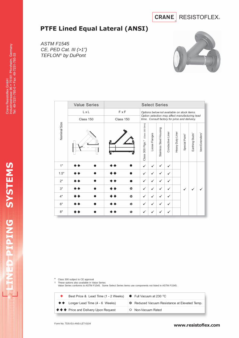
LIN
ED
P
IP
IN
G S
YS
TE
MS
Cra
ne R
esis
tofle
x G
mbH
Indu
strie
stra
sse
96 •
751
81 P
forz
heim
, G
erm
any
Tel:
49-7
231-
785-
0 •
Fax
: 49
-723
1-78
5-33
www.resistoflex.com
PTFE Lined Equal Lateral (ANSI)
ASTM F1545CE, PED Cat. III (>1”)TEFLON® by DuPont
Form No. TDS-EU-ANS-LET-0104
seireSeulaV seireStceleS
LxL FxF .smetikcotsnoelbaliavatonwolebsnoitpO
daelgnirutcafunamtceffayamnoitcelesnoitpO
.yrevileddnaecirprofyrotcaftlusnoC.emit051ssalC 051ssalC
"1
"5.1
"2
"3
"4
"6
"8
Nom
inal
Siz
e
Cla
ss 3
00 F
lgs.
*(C
lass
150
Dim
s)
Loos
e F
lang
es
Sta
inle
ss S
teel
Hou
sing
Con
duct
ive
Line
r
Hea
vy D
uty
Line
r
Spe
cial
Pai
nt†
Ear
thin
g S
tuds
†
Ven
t Ext
ende
rs†
* Class 300 subject to CE approval† These options also available in Value Series
Value Series conforms to ASTM F1545. Some Select Series items use components not listed in ASTM F1545.
)skeeW2-1(emiTdaeL&ecirPtseB 032tamuucaVlluF OC
)skeeW6-4(emiTdaeLregnoL .pmeTdetavelEtaecnatsiseRmuucaVdecudeR
tseuqeRnopUyrevileDdnaecirP detaRmuucaV-noN

www.resistoflex.com
LIN
ED
P
IP
IN
G S
YS
TE
MS
Cra
ne R
esis
tofle
x G
mbH
Indu
strie
stra
sse
96 •
751
81 P
forz
heim
, G
erm
any
Tel:
49-7
231-
785-
0 •
Fax
: 49
-723
1-78
5-33
PTFE Lined Equal Lateral (ANSI)
Welded Steel
Dimensional Data per Class 150
Notes:
1.) Drawing shows typical Value Series construction
2.) Vent holes are located on side of tee in center.
3.) Weld buttons are located approximately 25mm
behind each flange.
Part Number System
FinishedLateral
Tee15 - ANSI 15030 - ANSI 300
FF - Fixed/FixedFL - Fixed/LooseLL - Loose/Loose
W - WhiteE - Anti-Static
Factory Defined
0XX - Standard052 - Earthing Stud054 - Vent Boss070 - Stainless Steel
025 - 1”
040 - 1 1/2”
050 - 2”
080 - 3”
100 - 4”
150 - 6”
200 - 8”
1 - Value0 - Select
Diameter Pressure FlangesFittingType Liner Resin Type OptionsSeries
1 LTE 200 15 W FF 0XXXX 0
eziSL
)mm(
Y
)mm(
Z
)mm(
C
)mm(
)mm(SthgieW
)gK.ac(eulaV
seireS
tceleS
seireS
"1 191 641 54 15 5 5.3 2.5
"5.1 922 871 15 37 5 5.4 1.8
"2 762 302 46 29 5 5.4 4.11
"3 033 452 67 721 7 5 42
"4 183 503 67 751 7 6 44
"6 754 863 98 612 01 7 9.56
"8 955 544 411 072 21 01 5.99

LIN
ED
P
IP
IN
G S
YS
TE
MS
Cra
ne R
esis
tofle
x G
mbH
Indu
strie
stra
sse
96 •
751
81 P
forz
heim
, G
erm
any
Tel:
49-7
231-
785-
0 •
Fax
: 49
-723
1-78
5-33
www.resistoflex.com
PTFE Lined Reducing Flange(ANSI)
ASTM F1545CE, PED Cat. III (>1”)TEFLON® by DuPont
1” - 6”
Form No. TDS-EU-ANS-RFT-1-6-0104
* Class 300 subject to CE approvalSome Select Series items use components not listed in ASTM F1545.
seireSeulaV seireStceleS
seireSeulaV
segnalFgnicudeR
elbaliavAtoN
051ssalC
kcotsnoelbaliavatonwolebsnoitpO
tceffayamnoitcelesnoitpO.smeti
tlusnoC.emitdaelgnirutcafunam
.yrevileddnaecirprofyrotcaf
"1"2/1
"4/3
"2/11"4/3
"1
"2"1
"2/11
"3
"1
"2/11
"2
"4
"1
"2/11
"2
"3
"6
"2
"3
"4
Maj
or S
ize
Min
or S
ize
Cla
ss 3
00 D
rillin
g
Sta
inle
ss S
teel
Hou
sing
Con
duct
ive
Line
r
Hea
vy D
uty
Line
r
Spe
cial
Pai
nt
Ear
thin
g S
tuds
Ecc
entr
ic
)skeeW2-1(emiTdaeL&ecirPtseB 032tamuucaVlluF OC
)skeeW6-4(emiTdaeLregnoL .pmeTdetavelEtaecnatsiseRmuucaVdecudeR
tseuqeRnopUyrevileDdnaecirP detaRmuucaV-noN

www.resistoflex.com
LIN
ED
P
IP
IN
G S
YS
TE
MS
Cra
ne R
esis
tofle
x G
mbH
Indu
strie
stra
sse
96 •
751
81 P
forz
heim
, G
erm
any
Tel:
49-7
231-
785-
0 •
Fax
: 49
-723
1-78
5-33
PTFE Lined Reducing Flange (ANSI)
Carbon Steel
1” - 6”
Dimensional Data per Class 150
Notes:
1.) Vent holes are located on side of reducer in
center.
Part Number System
FinishedReducing
Flange15 - ANSI 15030 - ANSI 300
00 - Flange FittingW - WhiteE - Anti-Static
Factory Defined
0XX - Standard052 - Earthing Stud054 - Vent Boss070 - Stainless Steel
1 - Value0 - Select
Diameter Pressure FlangesFittingType Liner Resin Type OptionsSeries
1 RFK XXX 15 W 00 0XXXX 0
Consult Factory
A - Minor size bolt holes straddle the natural centerline.B - Major size bolt holes are threaded.C - Minor size bolt holes are on the natural centerline.
All major size bolt holes straddle the natural centerline.
rojaM
eziS
roniM
eziS)mm(L C
1C2
S +
%01
)mm(
RtloB
seloH
thgieW
)gK.ac(
"1"2/1
53 1553
5.3 54 o C1.2
"4/3 34 4.2
"5.1"4/3
53 3734
4 54 o C4
"1 15 1.4
"2"1
53 2915
40o B 9.4
"5.1 37 54 o C 1.5
"3
"1
53 721
15 5.3/40o
A 8.6
"5.1 374
B 6.6
"2 29 54 o C 4.6
"4
"1
54 851
15 5.3/5.4
5.22 o
A
21
"5.1 37
4/5.4
21
"2 29 21
"3 721 B 01
"6
"2
54 612
294/5 5.22 o A
91
"3 721 81
"4 851 5.4/5 0o B 71

LIN
ED
P
IP
IN
G S
YS
TE
MS
Cra
ne R
esis
tofle
x G
mbH
Indu
strie
stra
sse
96 •
751
81 P
forz
heim
, G
erm
any
Tel:
49-7
231-
785-
0 •
Fax
: 49
-723
1-78
5-33
www.resistoflex.com
PTFE Lined Reducing Flange(ANSI)
ASTM F1545CE, PED Cat. III (>1”)TEFLON® by DuPont
8” - 14”
Form No. TDS-EU-ANS-RFT-8-14-0104
* Class 300 subject to CE approvalSome Select Series items use components not listed in ASTM F1545.
seireSeulaV seireStceleS
seireSeulaV
segnalFgnicudeR
elbaliavAtoN
051ssalC
kcotsnoelbaliavatonwolebsnoitpO
tceffayamnoitcelesnoitpO.smeti
tlusnoC.emitdaelgnirutcafunam
.yrevileddnaecirprofyrotcaf
"8
"2
"3
"4
"01
"3
"4
"6
"8
"21
"6
"8
"01
"41
"8
"01
"21
Maj
or S
ize
Min
or S
ize
Cla
ss 3
00*
Dril
ling
Sta
inle
ss S
teel
Hou
sing
Con
duct
ive
Line
r
Hea
vy D
uty
Line
r
Spe
cial
Pai
nt
Ear
thin
g S
tuds
Ecc
entr
ic
)skeeW2-1(emiTdaeL&ecirPtseB 032tamuucaVlluF OC
)skeeW6-4(emiTdaeLregnoL .pmeTdetavelEtaecnatsiseRmuucaVdecudeR
tseuqeRnopUyrevileDdnaecirP detaRmuucaV-noN

www.resistoflex.com
LIN
ED
P
IP
IN
G S
YS
TE
MS
Cra
ne R
esis
tofle
x G
mbH
Indu
strie
stra
sse
96 •
751
81 P
forz
heim
, G
erm
any
Tel:
49-7
231-
785-
0 •
Fax
: 49
-723
1-78
5-33
PTFE Lined Reducing Flange (ANSI)
Carbon Steel
8” - 14”
Dimensional Data per Class 150
Part Number System
FinishedReducing
Flange15 - ANSI 15030 - ANSI 300 00 - Flange Fitting
W - WhiteE - Anti-Static
Factory Defined
0XX - Standard052 - Earthing Stud054 - Vent Boss070 - Stainless Steel
1 - Value0 - Select
Diameter Pressure FlangesFittingType Liner Resin Type OptionsSeries
1 RFK XXX 15 W 00 0XXXX 0
Consult Factory
A - Minor size bolt holes straddle the natural centerline.B - Major size bolt holes are threaded.C - Minor size bolt holes are on the natural centerline.
All major size bolt holes straddle the natural centerline.
rojaM
eziS
roniM
eziS)mm(L C
1C2
S +
%01
)mm(
RtloB
seloH
thgieW
)gK.ac(
"8
"2
54 072
294/5 5.22 o
A
82
"3 721 72
"4 851 5.4/5 0o 52
"01
"3
54 423
7214/6
0o
A
42
"4 851
5.7 o
22
"6 6125
91
"8 072 B 61
"21
"6
05 183
6124/6 5.7 o A
13
"8 072 82
"01 423 5.5 0o B 42
"41
"8
05 214
072 4/6 5.7 o
A83
"01 4236
0o 53
"21 183 51 o C 33

LIN
ED
P
IP
IN
G S
YS
TE
MS
Cra
ne R
esis
tofle
x G
mbH
Indu
strie
stra
sse
96 •
751
81 P
forz
heim
, G
erm
any
Tel:
49-7
231-
785-
0 •
Fax
: 49
-723
1-78
5-33
www.resistoflex.com
PTFE Lined Reducing Flange(ANSI)
ASTM F1545CE, PED Cat. III (>1”)TEFLON® by DuPont
16” - 24”
Form No. TDS-EU-ANS-RFT-16-24-0104
* Class 300 subject to CE approvalSome Select Series items use components not listed in ASTM F1545.
seireSeulaV seireStceleS
seireSeulaV
segnalFgnicudeR
elbaliavAtoN
051ssalC
kcotsnoelbaliavatonwolebsnoitpO
tceffayamnoitcelesnoitpO.smeti
tlusnoC.emitdaelgnirutcafunam
.yrevileddnaecirprofyrotcaf
"61
"01
"21
"41
"81
"21
"41
"61
"02
"21
"41
"61
"42
"21
"41
"61
Maj
or S
ize
Min
or S
ize
Cla
ss 3
00*
Dril
ling
Sta
inle
ss S
teel
Hou
sing
Con
duct
ive
Line
r
Hea
vy D
uty
Line
r
Spe
cial
Pai
nt
Ear
thin
g S
tuds
Ecc
entr
ic
)skeeW2-1(emiTdaeL&ecirPtseB 032tamuucaVlluF OC
)skeeW6-4(emiTdaeLregnoL .pmeTdetavelEtaecnatsiseRmuucaVdecudeR
tseuqeRnopUyrevileDdnaecirP detaRmuucaV-noN
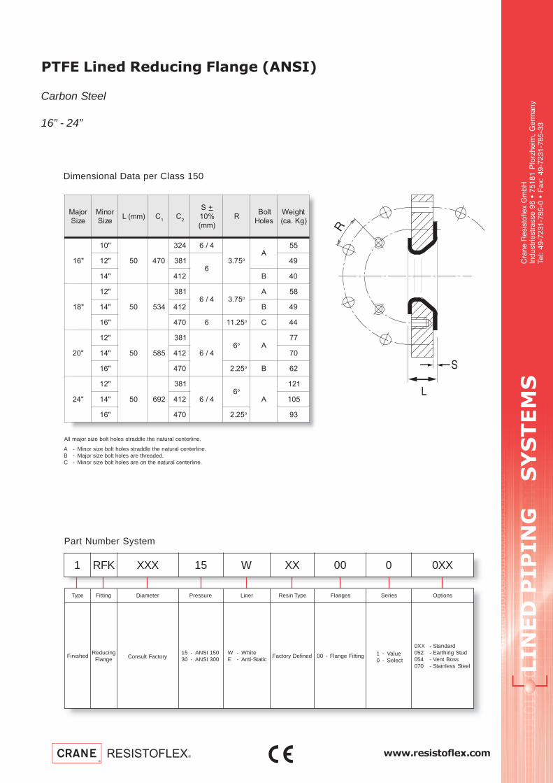
www.resistoflex.com
LIN
ED
P
IP
IN
G S
YS
TE
MS
Cra
ne R
esis
tofle
x G
mbH
Indu
strie
stra
sse
96 •
751
81 P
forz
heim
, G
erm
any
Tel:
49-7
231-
785-
0 •
Fax
: 49
-723
1-78
5-33
PTFE Lined Reducing Flange (ANSI)
Carbon Steel
16” - 24”
Dimensional Data per Class 150
Part Number System
FinishedReducing
Flange15 - ANSI 15030 - ANSI 300
00 - Flange FittingW - WhiteE - Anti-Static
Factory Defined
0XX - Standard052 - Earthing Stud054 - Vent Boss070 - Stainless Steel
1 - Value0 - Select
Diameter Pressure FlangesFittingType Liner Resin Type OptionsSeries
1 RFK XXX 15 W 00 0XXXX 0
Consult Factory
A - Minor size bolt holes straddle the natural centerline.B - Major size bolt holes are threaded.C - Minor size bolt holes are on the natural centerline.
All major size bolt holes straddle the natural centerline.
rojaM
eziS
roniM
eziS)mm(L C
1C2
S +
%01
)mm(
RtloB
seloH
thgieW
)gK.ac(
"61
"01
05 074
423 4/6
57.3 o
A55
"21 1836
94
"41 214 B 04
"81
"21
05 435
1834/6 57.3 o
A 85
"41 214 B 94
"61 074 6 52.11 o C 44
"02
"21
05 585
183
4/66o A
77
"41 214 07
"61 074 52.2 o B 26
"42
"21
05 296
183
4/66o
A
121
"41 214 501
"61 074 52.2 o 39

LIN
ED
P
IP
IN
G S
YS
TE
MS
Cra
ne R
esis
tofle
x G
mbH
Indu
strie
stra
sse
96 •
751
81 P
forz
heim
, G
erm
any
Tel:
49-7
231-
785-
0 •
Fax
: 49
-723
1-78
5-33
www.resistoflex.com
PTFE Lined Concentric Reducer(ANSI)
ASTM F1545CE, PED Cat. III (>1”)TEFLON® by DuPont
3/4” - 6”
)skeeW2-1(emiTdaeL&ecirPtseB 032tamuucaVlluF OC
)skeeW6-4(emiTdaeLregnoL .pmeTdetavelEtaecnatsiseRmuucaVdecudeR
tseuqeRnopUyrevileDdnaecirP detaRmuucaV-noN
Form No. TDS-EU-ANS-CRT-1-6-0104
* Class 300 subject to CE approval† These options also available in Value Series
Value Series conforms to ASTM F1545. Some Select Series items use components not listed in ASTM F1545.
seireSeulaV seireStceleS
LxF="4-"1
FxF="6FxF
.smetikcotsnoelbaliavatonwolebsnoitpO
gnirutcafunamtceffayamnoitcelesnoitpO
dnaecirprofyrotcaftlusnoC.emitdael
.yreviled051ssalC 051ssalC
"4/3 "2/1
"1"2/1
"4/3
"5.1"4/3
"1
"2"1
"5.1
"3
"1
"5.1
"2
"4
"1
"5.1
"2
"3
"6
"1
"2
"3
"4
Maj
or S
ize
Min
or S
ize
Cla
ss 3
00
Loos
e F
lang
es
Sta
inle
ss S
teel
Hou
sing
Con
duct
ive
Line
r
Hea
vy D
uty
Line
r
Spe
cial
Pai
nt†
Ear
thin
g S
tuds
†
Ven
t Ext
ende
rs†
1" - 4" = F x L6" = F x F

www.resistoflex.com
LIN
ED
P
IP
IN
G S
YS
TE
MS
Cra
ne R
esis
tofle
x G
mbH
Indu
strie
stra
sse
96 •
751
81 P
forz
heim
, G
erm
any
Tel:
49-7
231-
785-
0 •
Fax
: 49
-723
1-78
5-33
PTFE Lined Concentric Reducer (ANSI)
Welded Steel
3/4” - 6”
Dimensional Data per Class 150
Notes:
1.) Drawing shows typical Value Series construction.
2.) Vent holes are located on side of reducer in center.
3.) Weld buttons are located approximately 25mm behind
each flange.
Part Number System
FinishedConc.
Reducer15 - ANSI 15030 - ANSI 300
FF - Fixed/FixedFL - Fixed/LooseLL - Loose/Loose
W - WhiteE - Anti-Static
Factory Defined
0XX - Standard052 - Earthing Stud054 - Vent Boss070 - Stainless Steel
1 - Value0 - Select
Diameter Pressure FlangesFittingType Liner Resin Type OptionsSeries
1 RSK XXX 15 W FF 0XXXX 0
Consult Factory
rojaM
eziS
roniM
eziS)mm(L C
1C2
S + )mm(%01thgieW
)gK.ac(eulaV
seireS
tceleS
seireS
"4/3 "2/1 411 34 53 2 1.2
"1"2/1
411 1553
34.2
"4/3 34 4.2
"5.1"4/3
411 3734
9.23 1.3
"1 15 3 3.3
"2"1
721 2915
9.2 3/41.4
"5.1 37 5
"3
"1
251 721
15
9.33/4
7.6
"5.1 37 9.6
"2 29 4 8.7
"4
"1
871 851
15
9.3
3/5.42.01
"5.1 37 4.11
"2 29 4/5.4 3.21
"3 721 5.4 51
"6
"1
922 612
15 3/5 91
"2 292.4
4/5 02
"3 721 4/5 02
"4 851 5.4/5 7.32

LIN
ED
P
IP
IN
G S
YS
TE
MS
Cra
ne R
esis
tofle
x G
mbH
Indu
strie
stra
sse
96 •
751
81 P
forz
heim
, G
erm
any
Tel:
49-7
231-
785-
0 •
Fax
: 49
-723
1-78
5-33
www.resistoflex.com
PTFE Lined Concentric Reducer (ANSI)
ASTM F1545CE, Cat. III (>1”)TEFLON® by DuPont
8” - 24”
Form No. TDS-EU-ANS-RCT-8-24-0104
* Class 300 subject to CE approval† These options also available in Value Series
Value Series conforms to ASTM F1545. Some Select Series items use components not listed in ASTM F1545.
seireSeulaV seireStceleS
LxF="4-"1
FxF="6FxF
.smetikcotsnoelbaliavatonwolebsnoitpO
gnirutcafunamtceffayamnoitcelesnoitpO
dnaecirprofyrotcaftlusnoC.emitdael
.yreviled051ssalC 051ssalC
"8"4
"6
"01"6
"8
"21
"6
"8
"01
"41"01
"21
"61"21
"41
"81"41
"61
"02"61
"81
"42 "02
Maj
or S
ize
Min
or S
ize
Cla
ss 3
00
Loos
e F
lang
es
Sta
inle
ss S
teel
Hou
sing
Con
duct
ive
Line
r
Hea
vy D
uty
Line
r
Spe
cial
Pai
nt†
Ear
thin
g S
tuds
†
Ven
t Ext
ende
rs†
10", 12" = F x F8" = F x L
)skeeW2-1(emiTdaeL&ecirPtseB 032tamuucaVlluF OC
)skeeW6-4(emiTdaeLregnoL .pmeTdetavelEtaecnatsiseRmuucaVdecudeR
tseuqeRnopUyrevileDdnaecirP detaRmuucaV-noN

www.resistoflex.com
LIN
ED
P
IP
IN
G S
YS
TE
MS
Cra
ne R
esis
tofle
x G
mbH
Indu
strie
stra
sse
96 •
751
81 P
forz
heim
, G
erm
any
Tel:
49-7
231-
785-
0 •
Fax
: 49
-723
1-78
5-33
PTFE Lined Concentric Reducer (ANSI)
Welded Steel
8" - 24"
Dimensional Data per Class 150
Notes:
1.) Drawing shows typical Value Series construction.
2.) Vent holes are located in center of reducer.
3.) Weld buttons are located approximately 25mm behind
each flange.
Part Number System
FinishedConc.
Reducer15 - ANSI 15030 - ANSI 300
FF - Fixed/FixedFL - Fixed/LooseLL - Loose/Loose
W - WhiteE - Anti-Static
Factory Defined
0XX - Standard052 - Earthing Stud054 - Vent Boss070 - Stainless Steel
1 - Value0 - Select
Diameter Pressure FlangesFittingType Liner Resin Type OptionsSeries
1 RSK XXX 15 W FF 0XXXX 0
Consult Factory
rojaM
eziS
roniM
eziS)mm(L C
1C2
S + )mm(%01thgieW
)gK.ac(eulaV
seireS
tceleS
seireS
"8"4
972 072851
4.45.4/6 1.22
"6 612 5/6 2.52
"01"6
503 423612 4.4 5/5.6 8.73
"8 072 7.21 5.6 8.44
"21
"6
653 183
612
7.21 5.6
64
"8 072 84
"01 423 6.25
"41"01
604 214423
5.66.37
"21 183 08
"61"21
754 074183
5.6501
"41 214 511
"81"41
384 435214
5.6841
"61 074 751
"02"61
805 585074
5.6012
"81 435 812
"42"81
016 296435
5.4282
"02 585 192

LIN
ED
P
IP
IN
G S
YS
TE
MS
Cra
ne R
esis
tofle
x G
mbH
Indu
strie
stra
sse
96 •
751
81 P
forz
heim
, G
erm
any
Tel:
49-7
231-
785-
0 •
Fax
: 49
-723
1-78
5-33
www.resistoflex.com
PTFE Lined Eccentric Reducer(ANSI)
ASTM F1545CE, PED Cat. III (>1”)TEFLON® by DuPont
1” - 6”
Form No. TDS-EU-ANS-RET-1-6-0104
* Class 300 subject to CE approval† These options also available in Value Series
Value Series conforms to ASTM F1545. Some Select Series items use components not listed in ASTM F1545.
seireSeulaV seireStceleS
FxF FxF.smetikcotsnoelbaliavatonwolebsnoitpO
gnirutcafunamtceffayamnoitcelesnoitpO
dnaecirprofyrotcaftlusnoC.emitdael
.yreviled051ssalC 051ssalC
"1"2/1
"4/3
"5.1 "4/3
"2 "1
"3"2
"5.2
"4
"5.1
"2
"3
"6 "3
Maj
or S
ize
Min
or S
ize
Cla
ss 3
00
Loos
e F
lang
es
Sta
inle
ss S
teel
Hou
sing
Con
duct
ive
Line
r
Hea
vy D
uty
Line
r
Spe
cial
Pai
nt†
Ear
thin
g S
tuds
†
Ven
t Ext
ende
rs†
)skeeW2-1(emiTdaeL&ecirPtseB 032tamuucaVlluF OC
)skeeW6-4(emiTdaeLregnoL .pmeTdetavelEtaecnatsiseRmuucaVdecudeR
tseuqeRnopUyrevileDdnaecirP detaRmuucaV-noN
segnalFdexiF-ydoBnorIelitcuD
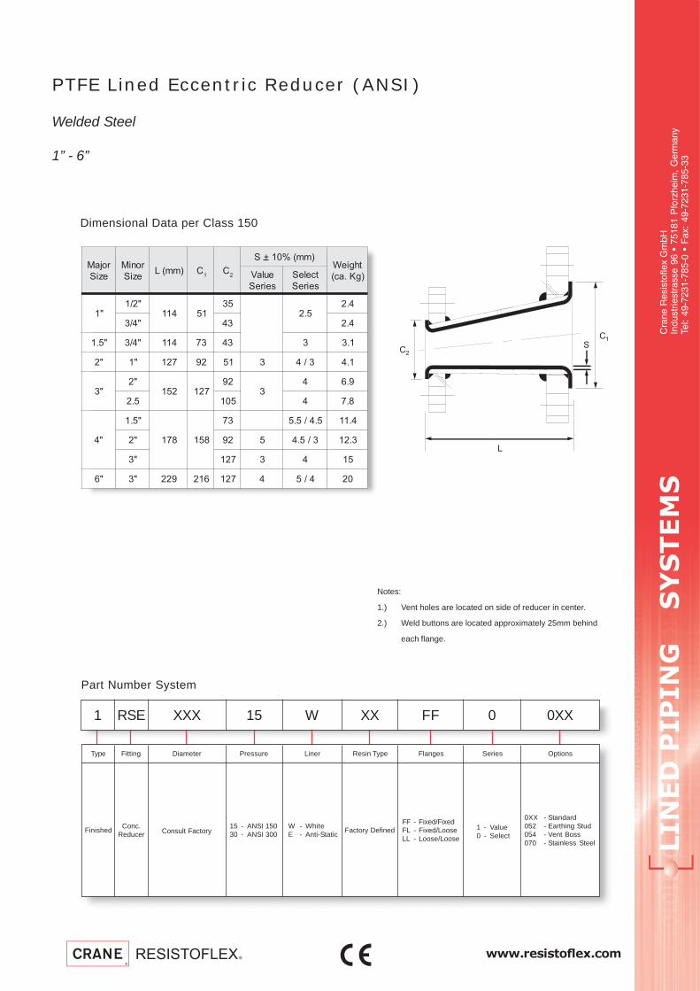
www.resistoflex.com
LIN
ED
P
IP
IN
G S
YS
TE
MS
Cra
ne R
esis
tofle
x G
mbH
Indu
strie
stra
sse
96 •
751
81 P
forz
heim
, G
erm
any
Tel:
49-7
231-
785-
0 •
Fax
: 49
-723
1-78
5-33
PTFE Lined Eccentric Reducer (ANSI)
Welded Steel
1” - 6”
Dimensional Data per Class 150
Notes:
1.) Vent holes are located on side of reducer in center.
2.) Weld buttons are located approximately 25mm behind
each flange.
Part Number System
FinishedConc.
Reducer15 - ANSI 15030 - ANSI 300
FF - Fixed/FixedFL - Fixed/LooseLL - Loose/Loose
W - WhiteE - Anti-Static
Factory Defined
0XX - Standard052 - Earthing Stud054 - Vent Boss070 - Stainless Steel
1 - Value0 - Select
Diameter Pressure FlangesFittingType Liner Resin Type OptionsSeries
1 RSE XXX 15 W FF 0XXXX 0
Consult Factory
rojaM
eziS
roniM
eziS)mm(L C
1C2
S + )mm(%01thgieW
)gK.ac(eulaV
seireS
tceleS
seireS
"1"2/1
411 1553
5.24.2
"4/3 34 4.2
"5.1 "4/3 411 37 34 3 1.3
"2 "1 721 29 15 3 3/4 1.4
"3"2
251 72129
34 9.6
5.2 501 4 8.7
"4
"5.1
871 851
37 5.4/5.5 4.11
"2 29 5 3/5.4 3.21
"3 721 3 4 51
"6 "3 922 612 721 4 4/5 02
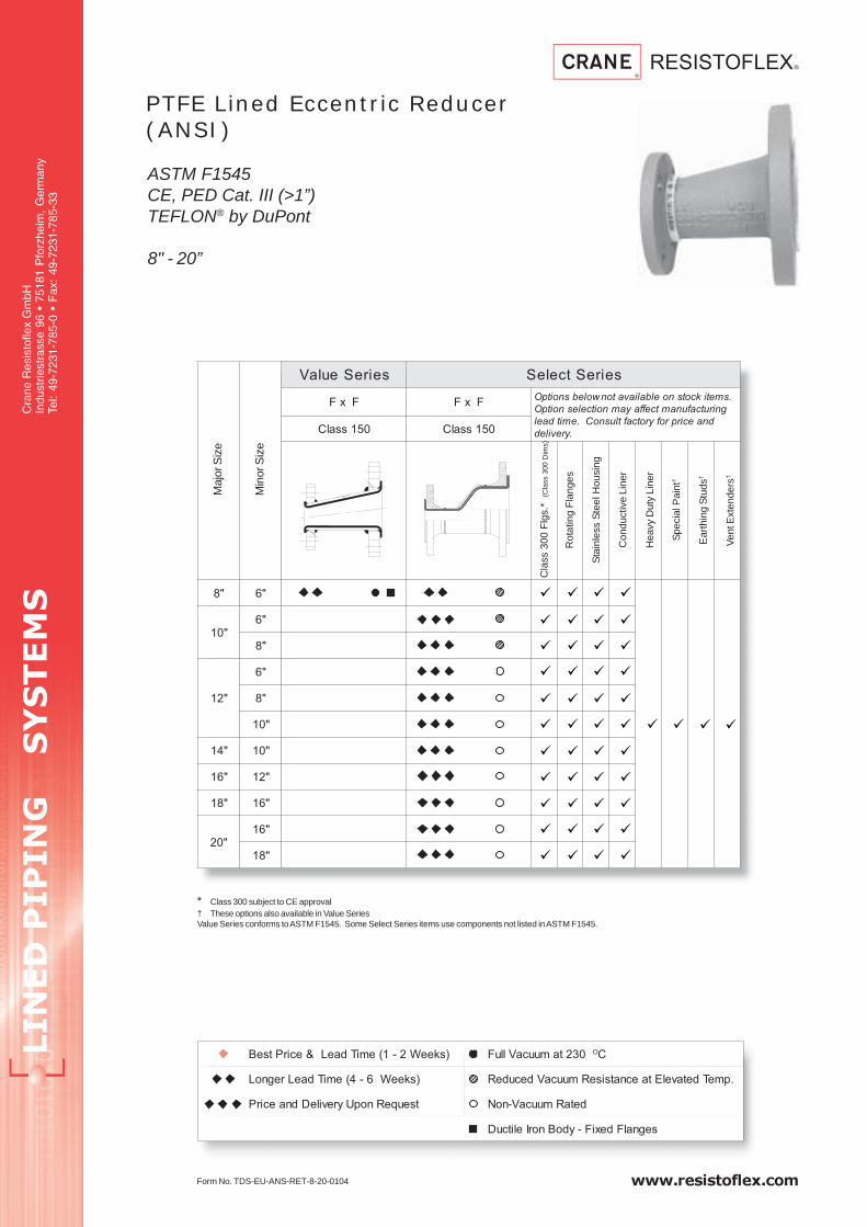
LIN
ED
P
IP
IN
G S
YS
TE
MS
Cra
ne R
esis
tofle
x G
mbH
Indu
strie
stra
sse
96 •
751
81 P
forz
heim
, G
erm
any
Tel:
49-7
231-
785-
0 •
Fax
: 49
-723
1-78
5-33
www.resistoflex.com
seireSeulaV seireStceleS
FxF FxF.smetikcotsnoelbaliavatonwolebsnoitpO
gnirutcafunamtceffayamnoitcelesnoitpO
dnaecirprofyrotcaftlusnoC.emitdael
.yreviled051ssalC 051ssalC
"8 "6
"01"6
"8
"21
"6
"8
"01
"41 "01
"61 "21
"81 "61
"02"61
"81
PTFE Lined Eccentric Reducer(ANSI)
ASTM F1545CE, PED Cat. III (>1”)TEFLON® by DuPont
8" - 20”
* Class 300 subject to CE approval† These options also available in Value SeriesValue Series conforms to ASTM F1545. Some Select Series items use components not listed in ASTM F1545.
Form No. TDS-EU-ANS-RET-8-20-0104
Maj
or S
ize
Min
or S
ize
Cla
ss 3
00 F
lgs.
*(C
lass
300
Dim
s)
Rot
atin
g F
lang
es
Sta
inle
ss S
teel
Hou
sing
Con
duct
ive
Line
r
Hea
vy D
uty
Line
r
Spe
cial
Pai
nt†
Ear
thin
g S
tuds
†
Ven
t Ext
ende
rs†
)skeeW2-1(emiTdaeL&ecirPtseB 032tamuucaVlluF OC
)skeeW6-4(emiTdaeLregnoL .pmeTdetavelEtaecnatsiseRmuucaVdecudeR
tseuqeRnopUyrevileDdnaecirP detaRmuucaV-noN
segnalFdexiF-ydoBnorIelitcuD

www.resistoflex.com
LIN
ED
P
IP
IN
G S
YS
TE
MS
Cra
ne R
esis
tofle
x G
mbH
Indu
strie
stra
sse
96 •
751
81 P
forz
heim
, G
erm
any
Tel:
49-7
231-
785-
0 •
Fax
: 49
-723
1-78
5-33
PTFE Lined Eccentric Reducer (ANSI)
Welded Steel
8” - 20”
Dimensional Data per Class 150
Notes:
1.) Drawing shows typical Value Series
construction.
2.) Vent holes are located on side of reducer
in center.
Part Number System
FinishedConc.
Reducer15 - ANSI 15030 - ANSI 300
FF - Fixed/FixedFL - Fixed/LooseLL - Loose/Loose
W - WhiteE - Anti-Static
Factory Defined
0XX - Standard052 - Earthing Stud054 - Vent Boss070 - Stainless Steel
1 - Value0 - Select
Diameter Pressure FlangesFittingType Liner Resin Type OptionsSeries
1 RSE XXX 15 W FF 0XXXX 0
Consult Factory
rojaM
eziS
roniM
eziS)mm(L C
1C2
S + )mm(%01thgieW
)gK.ac(eulaV
seireS
tceleS
seireS
"8 "6 972 072 612 5.7 5/6 1.52
"01"6
503 423612 5/6 8.73
"8 072 01 8.44
"21
"6
653 183
6125/5.6
64
"8 072 84
"01 423 6 6.25
"41 "01 604 214 423 6 6.37
"61"01
754 074423 6 79
"21 183 5.6 501
"81 "61 384 435 074 6 751
"02"61
805 585074
6012
"81 435 812

LIN
ED
P
IP
IN
G S
YS
TE
MS
Cra
ne R
esis
tofle
x G
mbH
Indu
strie
stra
sse
96 •
751
81 P
forz
heim
, G
erm
any
Tel:
49-7
231-
785-
0 •
Fax
: 49
-723
1-78
5-33
www.resistoflex.com
seireSeulaV seireStceleS
seireSeulaV
srecapS
elbaliavAtoN
noitcelesnoitpO
tceffayam
gnirutcafunam
.emitdael
rofyrotcaftlusnoC
.yrevileddnaecirp
"2/1
"4/3
"1
"5.1
"2
"3
"4
"6
"8
"01
"21
"41
"61
"81
"02
"42
PTFE Solid Spacer (ANSI)
ASTM F1545CE, PED Cat. III (>1”)TEFLON® by DuPont
)skeeW2-1(emiTdaeL&ecirPtseB 032tamuucaVlluF OC
)skeeW6-4(emiTdaeLregnoL .pmeTdetavelEtaecnatsiseRmuucaVdecudeR
tseuqeRnopUyrevileDdnaecirP detaRmuucaV-noN
Form No. TDS-EU-ANS-SST-0104
Some Select Series items use components not listed in ASTM F1545.
Nom
inal
Siz
e
Cla
ss 3
00

www.resistoflex.com
LIN
ED
P
IP
IN
G S
YS
TE
MS
Cra
ne R
esis
tofle
x G
mbH
Indu
strie
stra
sse
96 •
751
81 P
forz
heim
, G
erm
any
Tel:
49-7
231-
785-
0 •
Fax
: 49
-723
1-78
5-33
PTFE Solid Spacer (ANSI)
Dimensional Data
Part Number System
Finished Spacer 00 - Spacer 00 - SpacerW - White Factory Defined 0XX - Standard
200 -8”
250 -10”
300 -12”
350 -14”
400 -16”
450 -18”
500 -20”
600 -24”
015 - 1/2”
020 - 3/4”
025 - 1”
040 - 1 1/2”
050 - 2”
080 - 3”
100 - 4”
150 - 6”
0 - Select
Diameter Pressure FlangesFittingType Liner Resin Type OptionsSeries
1 DSF 250 00 W 00 0XXXX 0
eziSL.xaM
)mm(
1D
)mm(
2D
)mm(
thgieW
)gK.ac(
"2/1 02 41 53 1.0
"4/3 02 61 34 1.0
"1 02 22 15 2.0
"5.1 02 73 37 3.0
"2 02 84 29 4.0
"3 52 67 721 6.0
"4 52 101 851 57.0
"6 03 351 612 4.1
"8 03 102 072 0.2
"01 04 452 423 2.3
"21 04 303 183 0.4
"41 04 333 214 5.4
"61 04 283 074 2.5
"81 04 034 435 1.6
"02 04 084 585 2.7
"42 04 095 296 5.8
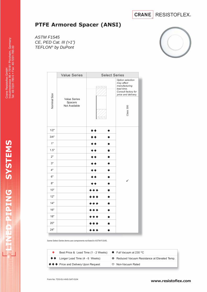
LIN
ED
P
IP
IN
G S
YS
TE
MS
Cra
ne R
esis
tofle
x G
mbH
Indu
strie
stra
sse
96 •
751
81 P
forz
heim
, G
erm
any
Tel:
49-7
231-
785-
0 •
Fax
: 49
-723
1-78
5-33
www.resistoflex.com
seireSeulaV seireStceleS
seireSeulaV
srecapS
elbaliavAtoN
noitcelesnoitpO
tceffayam
gnirutcafunam
.emitdael
rofyrotcaftlusnoC
.yrevileddnaecirp
"2/1
"4/3
"1
"5.1
"2
"3
"4
"6
"8
"01
"21
"41
"61
"81
"02
"42
PTFE Armored Spacer (ANSI)
ASTM F1545CE, PED Cat. III (>1”)TEFLON® by DuPont
)skeeW2-1(emiTdaeL&ecirPtseB 032tamuucaVlluF OC
)skeeW6-4(emiTdaeLregnoL .pmeTdetavelEtaecnatsiseRmuucaVdecudeR
tseuqeRnopUyrevileDdnaecirP detaRmuucaV-noN
Form No. TDS-EU-ANS-SAT-0104
Some Select Series items use components not listed in ASTM F1545.
Nom
inal
Siz
e
Cla
ss 3
00

www.resistoflex.com
LIN
ED
P
IP
IN
G S
YS
TE
MS
Cra
ne R
esis
tofle
x G
mbH
Indu
strie
stra
sse
96 •
751
81 P
forz
heim
, G
erm
any
Tel:
49-7
231-
785-
0 •
Fax
: 49
-723
1-78
5-33
PTFE Armored Spacer (ANSI)
Dimensional Data
Part Number System
Finished ArmoredSpacer
00 - Spacer 00 - SpacerW - White Factory Defined 0XX - Standard
200 -8”
250 -10”
300 -12”
350 -14”
400 -16”
450 -18”
500 -20”
600 -24”
015 - 1/2”
020 - 3/4”
025 - 1”
040 - 1 1/2”
050 - 2”
080 - 3”
100 - 4”
150 - 6”
0 - Select
Diameter Pressure FlangesFittingType Liner Resin Type OptionsSeries
1 DSX 250 00 W 00 0XXXX 0
eziSL.xaM
)mm(
S
)mm(
1D
)mm(
2D
)mm(
thgieW
)gK.ac(
"2/1 02 2 41 7.33 1.0
"4/3 02 3.2 61 4.24 1.0
"1 02 3.2 22 45 2.0
"5.1 02 6.2 73 37 3.0
"2 02 9.2 84 6.101 4.0
"3 52 2.3 67 721 6.0
"4 52 4 101 951 57.0
"6 03 5.4 351 1.912 4.1
"8 03 5 102 372 0.2
"01 04 6.5 452 9.323 2.3
"21 04 5 303 183 0.4
"41 04 3.6 333 4.604 5.4
"61 04 6 283 074 2.5
"81 04 6 034 435 1.6
"02 04 6 084 585 2.7
"42 04 6 095 296 5.8

LIN
ED
P
IP
IN
G S
YS
TE
MS
Cra
ne R
esis
tofle
x G
mbH
Indu
strie
stra
sse
96 •
751
81 P
forz
heim
, G
erm
any
Tel:
49-7
231-
785-
0 •
Fax
: 49
-723
1-78
5-33
www.resistoflex.com
PTFE Lined Ring Spacer (ANSI)
ASTM F1545CE, PED Cat. III (>1”)TEFLON® by DuPont
Form No. TDS-EU-ANS-SGT-0104
* Class 300 subject to CE approvalSome Select Series items use components not listed in ASTM F1545.
seireSeulaV seireStceleS
srecapSgniRdeniL
nielbaliavAtoN
seireSeulaV
FxF kcotsnoelbaliavatonwolebsnoitpO
tceffayamnoitcelesnoitpO.smeti
tlusnoC.emitdaelgnirutcafunam
.yrevileddnaecirprofyrotcaf051ssalC
"2/1
"4/3
"1
"2/11
"2
"3
"4
"6
"8
"01
"21
"41
"61
"81
"02
"42
Nom
inal
Siz
e
Cla
ss 3
00*
Sta
inle
ss S
teel
Hou
sing
Con
duct
ive
Line
r
Hea
vy D
uty
Line
r
Spe
cial
Pai
nt
Ear
thin
g S
tuds
Ven
t Ext
ende
rs
)skeeW2-1(emiTdaeL&ecirPtseB 032tamuucaVlluF OC
)skeeW6-4(emiTdaeLregnoL .pmeTdetavelEtaecnatsiseRmuucaVdecudeR
tseuqeRnopUyrevileDdnaecirP detaRmuucaV-noN

www.resistoflex.com
LIN
ED
P
IP
IN
G S
YS
TE
MS
Cra
ne R
esis
tofle
x G
mbH
Indu
strie
stra
sse
96 •
751
81 P
forz
heim
, G
erm
any
Tel:
49-7
231-
785-
0 •
Fax
: 49
-723
1-78
5-33
PTFE Lined Ring Spacer (ANSI)
Carbon Steel
Notes:
1.) Drawing shows typical Select Series construction
Dimensional Data per Class 150
Part Number System
FinishedLinedRing
Spacer
15 - ANSI 15030 - ANSI 300 00 - Spacer
W - WhiteE - Anti-Static
Factory Defined
0XX - Standard052 - Earthing Stud054 - Vent Boss070 - Stainless Steel
200 -8”
250 -10”
300 -12”
350 -14”
400 -16”
450 -18”
500 -20”
600 -24”
015 - 1/2”
020 - 3/4”
025 - 1”
040 - 1 1/2”
050 - 2”
080 - 3”
100 - 4”
150 - 6”
0 - Select
Diameter Pressure FlangesFittingType Liner Resin Type OptionsSeries
1 DSG 250 15 W 00 0XXXX 0
eziSL.niM
)mm(
L.xaM
)mm(
S
)mm(
C
)mm(
D
)mm(
thgieW
)m/gKac(
"2/1 02 511 5.2 53 44 9.0
"4/3 02 031 3 34 35 2.1
"1 02 041 3 15 36 8.1
"5.1 02 051 3 37 28 6.2
"2 02 551 3 29 001 7.3
"3 52 581 5.3 721 331 3.5
"4 52 002 5.4 851 071 5.9
"6 03 532 5 612 812 41
"8 03 562 52.6 072 672 81
"01 04 072 57.6 423 633 92
"21 04 582 8 183 604 03
"41 04 023 9 214 744 05
"61 04 523 01 074 015 06
"81 04 043 5.7 435 545 17
"02 06 563 5.6 585 206 57
"42 06 573 5.4 296 417 311
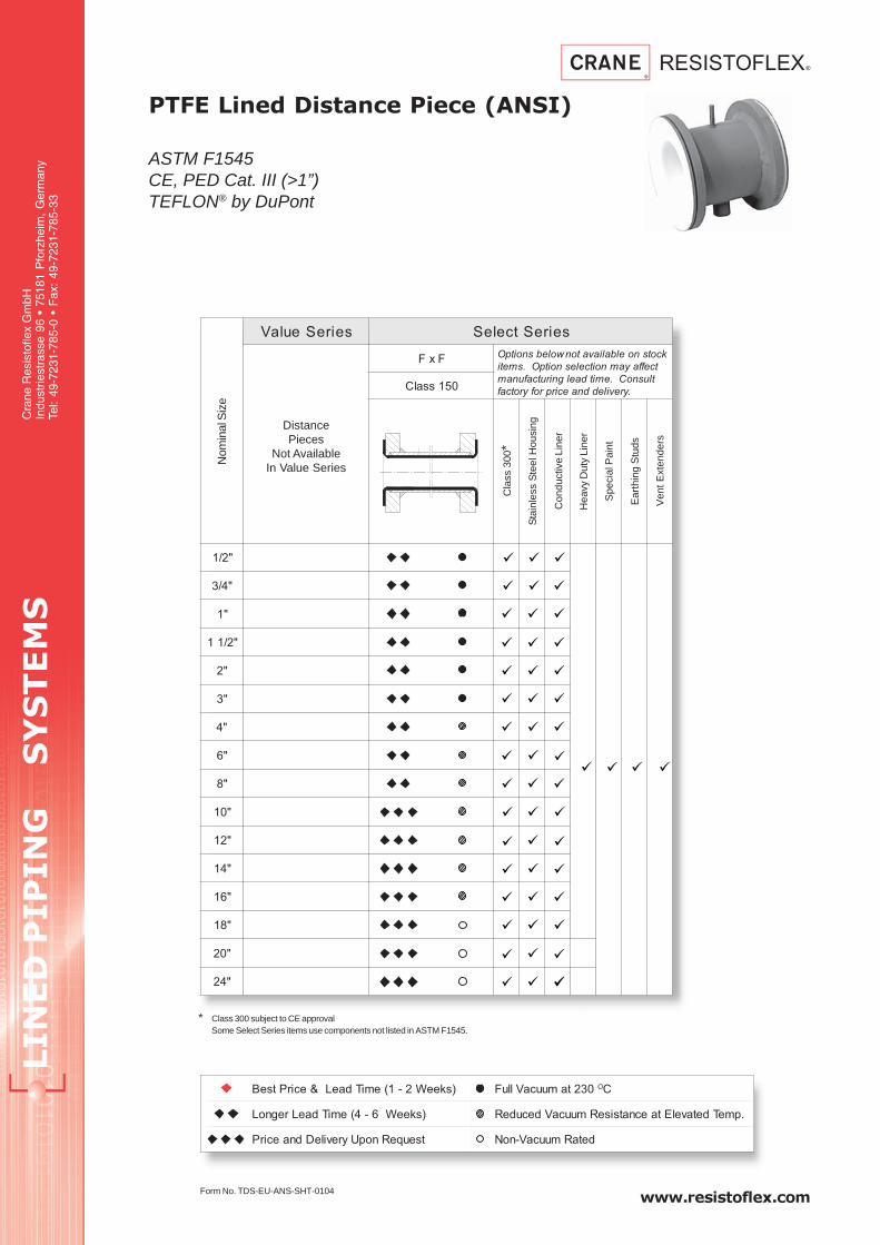
LIN
ED
P
IP
IN
G S
YS
TE
MS
Cra
ne R
esis
tofle
x G
mbH
Indu
strie
stra
sse
96 •
751
81 P
forz
heim
, G
erm
any
Tel:
49-7
231-
785-
0 •
Fax
: 49
-723
1-78
5-33
www.resistoflex.com
PTFE Lined Distance Piece (ANSI)
ASTM F1545CE, PED Cat. III (>1”)TEFLON® by DuPont
Form No. TDS-EU-ANS-SHT-0104
* Class 300 subject to CE approvalSome Select Series items use components not listed in ASTM F1545.
seireSeulaV seireStceleS
srecapSgniRdeniL
nielbaliavAtoN
seireSeulaV
FxF kcotsnoelbaliavatonwolebsnoitpO
tceffayamnoitcelesnoitpO.smeti
tlusnoC.emitdaelgnirutcafunam
.yrevileddnaecirprofyrotcaf051ssalC
"2/1
"4/3
"1
"2/11
"2
"3
"4
"6
"8
"01
"21
"41
"61
"81
"02
"42
Cla
ss 3
00*
Sta
inle
ss S
teel
Hou
sing
Ear
thin
g S
tuds
Ven
t Ext
ende
rs
Con
duct
ive
Line
r
Hea
vy D
uty
Line
r
Spe
cial
Pai
nt
Nom
inal
Siz
e
DistancePieces
Not AvailableIn Value Series
)skeeW2-1(emiTdaeL&ecirPtseB 032tamuucaVlluF OC
)skeeW6-4(emiTdaeLregnoL .pmeTdetavelEtaecnatsiseRmuucaVdecudeR
tseuqeRnopUyrevileDdnaecirP detaRmuucaV-noN
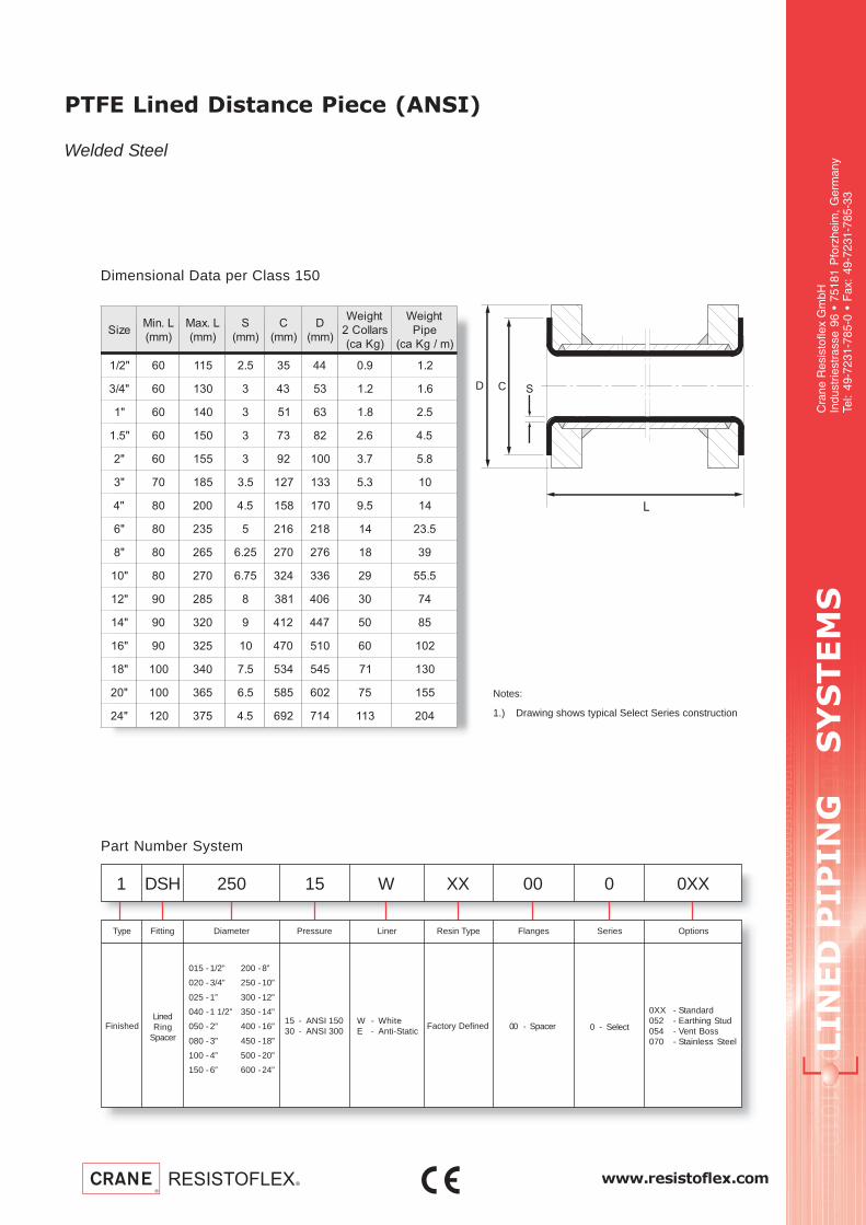
www.resistoflex.com
LIN
ED
P
IP
IN
G S
YS
TE
MS
Cra
ne R
esis
tofle
x G
mbH
Indu
strie
stra
sse
96 •
751
81 P
forz
heim
, G
erm
any
Tel:
49-7
231-
785-
0 •
Fax
: 49
-723
1-78
5-33
PTFE Lined Distance Piece (ANSI)
Welded Steel
Notes:
1.) Drawing shows typical Select Series construction
Dimensional Data per Class 150
Part Number System
FinishedLinedRing
Spacer
15 - ANSI 15030 - ANSI 300 00 - Spacer
W - WhiteE - Anti-Static
Factory Defined
0XX - Standard052 - Earthing Stud054 - Vent Boss070 - Stainless Steel
200 -8”
250 -10”
300 -12”
350 -14”
400 -16”
450 -18”
500 -20”
600 -24”
015 - 1/2”
020 - 3/4”
025 - 1”
040 - 1 1/2”
050 - 2”
080 - 3”
100 - 4”
150 - 6”
0 - Select
Diameter Pressure FlangesFittingType Liner Resin Type OptionsSeries
1 DSH 250 15 W 00 0XXXX 0
eziSL.niM
)mm(
L.xaM
)mm(
S
)mm(
C
)mm(
D
)mm(
thgieW
sralloC2
)gKac(
thgieW
epiP
)m/gKac(
"2/1 06 511 5.2 53 44 9.0 2.1
"4/3 06 031 3 34 35 2.1 6.1
"1 06 041 3 15 36 8.1 5.2
"5.1 06 051 3 37 28 6.2 5.4
"2 06 551 3 29 001 7.3 8.5
"3 07 581 5.3 721 331 3.5 01
"4 08 002 5.4 851 071 5.9 41
"6 08 532 5 612 812 41 5.32
"8 08 562 52.6 072 672 81 93
"01 08 072 57.6 423 633 92 5.55
"21 09 582 8 183 604 03 47
"41 09 023 9 214 744 05 58
"61 09 523 01 074 015 06 201
"81 001 043 5.7 435 545 17 031
"02 001 563 5.6 585 206 57 551
"42 021 573 5.4 296 417 311 402

LIN
ED
P
IP
IN
G S
YS
TE
MS
Cra
ne R
esis
tofle
x G
mbH
Indu
strie
stra
sse
96 •
751
81 P
forz
heim
, G
erm
any
Tel:
49-7
231-
785-
0 •
Fax
: 49
-723
1-78
5-33
www.resistoflex.com
PTFE Lined Spectacle Blind(ANSI)
ASTM F1545CE, PED Cat. III (>1”)TEFLON® by DuPont
* Class 300 subject to CE approvalSome Select Series items use components not listed in ASTM F1545
Form No. TDS-EU-ANS-SBT-0104
seireSeulaV seireStceleS
seireSeulaV
dnilBelcatcepS
elbaliavAtoN
051ssalC
elbaliavatonwolebsnoitpO
noitpO.smetikcotsno
tceffayamnoitceles
.emitdaelgnirutcafunam
ecirprofyrotcaftlusnoC
.yrevileddna
"2/1
"4/3
"1
"5.1
"2
"3
"4
"6
"8
"01
"21
"41
"61
"81
"02
"42
Nom
inal
Siz
e
Cla
ss 3
00*
Sta
inle
ss S
teel
Hou
sing
Con
duct
ive
Line
r
Hea
vy D
uty
Line
r
Spe
cial
Pai
nt
Ear
thin
g S
tuds
)skeeW2-1(emiTdaeL&ecirPtseB 032tamuucaVlluF OC
)skeeW6-4(emiTdaeLregnoL .pmeTdetavelEtaecnatsiseRmuucaVdecudeR
tseuqeRnopUyrevileDdnaecirP detaRmuucaV-noN

www.resistoflex.com
LIN
ED
P
IP
IN
G S
YS
TE
MS
Cra
ne R
esis
tofle
x G
mbH
Indu
strie
stra
sse
96 •
751
81 P
forz
heim
, G
erm
any
Tel:
49-7
231-
785-
0 •
Fax
: 49
-723
1-78
5-33
PTFE Lined Spectacle Blind (ANSI)
Carbon Steel
Notes:
1.) Drawing shows typical Select Series construction
Dimensional Data per Class 150
Part Number System
Finished SpectacleBlind
15 - ANSI 15030 - ANSI 300
00 - Spec. BlindW - WhiteE - Anti-Static
Factory Defined
0XX - Standard052 - Earthing Stud054 - Vent Boss070 - Stainless Steel
200 -8”
250 -10”
300 -12”
350 -14”
400 -16”
450 -18”
500 -20”
600 -24”
015 - 1/2”
020 - 3/4”
025 - 1”
040 - 1 1/2”
050 - 2”
080 - 3”
100 - 4”
150 - 6”
0 - Select
Diameter Pressure FlangesFittingType Liner Resin Type OptionsSeries
1 BRL 250 15 W 00 0XXXX 0
eziS )mm(L S K 2d 4dthgieW
)gKac(
"2/1 81 3 5.06 9.51 53 5.0
"4/3 02 3 9.96 9.51 34 55.0
"1 02 3 4.97 9.51 15 7.0
"5.1 42 3 4.89 9.51 37 2.1
"2 52 5.4 6.021 91 29 4.1
"3 03 6 4.251 91 721 3
"4 03 5.6 5.091 91 851 4
"6 23 5 3.142 2.22 612 5.7
"8 53 52.6 4.892 2.22 072 21
"01 53 57.6 9.163 4.52 423 71
"21 83 5.6 8.134 4.52 183 82
"41 54 5.6 2.674 6.82 214 44
"61 05 5.6 7.935 6.82 074 56
"81 25 5.6 8.775 8.13 435 77
"02 65 5.6 536 8.13 485 201
"42 75 5.4 3.947 1.53 296 651

LIN
ED
P
IP
IN
G S
YS
TE
MS
Cra
ne R
esis
tofle
x G
mbH
Indu
strie
stra
sse
96 •
751
81 P
forz
heim
, G
erm
any
Tel:
49-7
231-
785-
0 •
Fax
: 49
-723
1-78
5-33
www.resistoflex.com
PTFE Lined Blind Flange (ANSI)
ASTM F1545CE, PED Cat. III (>1”)TEFLON® by DuPont
seireSeulaV seireStceleS
051ssalC 051ssalC
elbaliavatonwolebsnoitpO
noitpO.smetikcotsno
tceffayamnoitceles
.emitdaelgnirutcafunam
ecirprofyrotcaftlusnoC
.yrevileddna
"2/1
"4/3
"1
"5.1
"2
"3
"4
"6
"8
"01
"21
"41
"61
"81
"02
"42
Nom
inal
Siz
e
Cla
ss 3
00*
Sta
inle
ss S
teel
Hou
sing
Con
duct
ive
Line
r
Hea
vy D
uty
Line
r
Spe
cial
Pai
nt†
Ear
thin
g S
tuds
†
* Class 300 subject to CE approval† These options also available in Value SeriesValue Series conforms to ASTM F1545. Some Select Series items use components not listed in ASTM F1545.
Form No. TDS-EU-ANS-FBT-1004
)skeeW2-1(emiTdaeL&ecirPtseB 032tamuucaVlluF OC
)skeeW6-4(emiTdaeLregnoL .pmeTdetavelEtaecnatsiseRmuucaVdecudeR
tseuqeRnopUyrevileDdnaecirP detaRmuucaV-noN

www.resistoflex.com
LIN
ED
P
IP
IN
G S
YS
TE
MS
Cra
ne R
esis
tofle
x G
mbH
Indu
strie
stra
sse
96 •
751
81 P
forz
heim
, G
erm
any
Tel:
49-7
231-
785-
0 •
Fax
: 49
-723
1-78
5-33
PTFE Lined Blind Flange (ANSI)
Welded Steel
Notes:
1.) Drawing shows typical Value Series
construction
Dimensional Data per Class 150
Part Number System
FinishedBlind
Flange15 - ANSI 15030 - ANSI 300
00 - Flange FittingW - WhiteE - Anti-Static
Factory Defined
0XX - Standard052 - Earthing Stud054 - Vent Boss070 - Stainless Steel
200 -8”
250 -10”
300 -12”
350 -14”
400 -16”
450 -18”
500 -20”
600 -24”
015 - 1/2”
020 - 3/4”
025 - 1”
040 - 1 1/2”
050 - 2”
080 - 3”
100 - 4”
150 - 6”
1 - Value0 - Select
Diameter Pressure FlangesFittingType Liner Resin Type OptionsSeries
1 BFL 250 15 W 00 0XXXX 0
C
eziS
)mm(L
)mm(C
S + )mm(%01thgieW
)gk.ac(eulaV
seireS
tceleS
seireS
eulaV
seireS
tceleS
seireS
"2/1 41 53 3 6.0
"4/3 61 34 3 8.0
"1 91 71 15 5 3 1
"5.1 12 02 37 5 3 7.1
"2 42 22 29 5 3 6.2
"3 92 72 721 5 5.3 2.5
"4 92 82 751 5 5.4 2.7
"6 03 03 612 5 5 21
"8 33 072 5 02
"01 53 423 5 5.92
"21 73 183 5 44
"41 04 214 5 5.85
"61 34 074 6 77
"81 64 435 6 59
"02 94 585 6 421
"42 45 296 6 781

LIN
ED
P
IP
IN
G S
YS
TE
MS
Cra
ne R
esis
tofle
x G
mbH
Indu
strie
stra
sse
96 •
751
81 P
forz
heim
, G
erm
any
Tel:
49-7
231-
785-
0 •
Fax
: 49
-723
1-78
5-33
www.resistoflex.com
seireSeulaV seireStceleS
sloopSepiPtneB
nielbaliavAtoN
seireSeulaV
FxF kcotsnoelbaliavatonwolebsnoitpO
tceffayamnoitcelesnoitpO.smeti
tlusnoC.emitdaelgnirutcafunam
.yrevileddnaecirprofyrotcaf051ssalC
"1
"2/11
"2
"3
PTFE Lined Bent Pipe Spool(ANSI)
ASTM F1545CE, PED Cat. III (>1”)TEFLON® by DuPont
Form No. TDS-EU-ANS-PBT-0104
* Class 300 subject to CE approvalSome Select Series items use components not listed in ASTM F1545.
Nom
inal
Siz
e
Cla
ss 3
00*
Sta
inle
ss S
teel
Hou
sing
Con
duct
ive
Line
r
Hea
vy D
uty
Line
r
Spe
cial
Pai
nt
Ear
thin
g S
tuds
Ven
t Ext
ende
rs
)skeeW2-1(emiTdaeL&ecirPtseB 032tamuucaVlluF OC
)skeeW6-4(emiTdaeLregnoL .pmeTdetavelEtaecnatsiseRmuucaVdecudeR
tseuqeRnopUyrevileDdnaecirP detaRmuucaV-noN

www.resistoflex.com
LIN
ED
P
IP
IN
G S
YS
TE
MS
Cra
ne R
esis
tofle
x G
mbH
Indu
strie
stra
sse
96 •
751
81 P
forz
heim
, G
erm
any
Tel:
49-7
231-
785-
0 •
Fax
: 49
-723
1-78
5-33
PTFE Lined Bent Pipe Spool (ANSI)
Carbon Steel
Dimensional Data
Part Number System
FinishedBentLinedPipe
15 - ANSI 15030 - ANSI 300
LL - Loose/LooseFL - Fixed/LooseFF - Fixed/Fixed
W - WhiteE - Anti-Static
Factory Defined
0XX - Standard052 - Earthing Stud054 - Vent Boss070 - Stainless Steel
025 -1”
040 -1 1/2”
050 -2”
080 -3”
0 - Select
Diameter Pressure FlangesFittingType Liner Resin Type OptionsSeries
1 ROG 250 15 W LL 0XXXX 0
0104
• The straight length of the pipe spool before bending can be up to 6 meters maximum.
• The straight lengths of the pipe spools before bending have to be calculated and are shorter than the sum of thecenter-center and center- face dimensions.
• The bend angles are available from 0o to 180o. Tolerances are + 0.5o in all three dimensions. Also important is the angleof twist, or roll.
• Due to the high stress imparted to the steel and PTFE during bending, it may not be possible to meet custom requirements that are different than the values in the table.
• After bending, the ovality of the pipe will be within 6.5% of original values, and the pipe wall thickness will be within15% of original thickness.
• Pipe Material will be RSt 37.0 WBN acc. to AD-W4
eziS
snoisnemiDepiPleetSEFTP
reniL
ssenkcihT
)mm(
dneB
suidaR
)mm(
snoisnemiDgeLmuminiM
edistuO
retemaiD
)mm(
llaWepiP
ssenkcihT
)mm(
A
)mm(
C
)mm(
D
)mm(
"1 7.33 6.3 3 5.27 502 514 023
"5.1 3.84 2.3 3 5.701 053 064 045
"2 3.06 6.3 3 531 573 045 085
"3 9.88 4 5.3 412 564 006 076

LIN
ED
P
IP
IN
G S
YS
TE
MS
Cra
ne R
esis
tofle
x G
mbH
Indu
strie
stra
sse
96 •
751
81 P
forz
heim
, G
erm
any
Tel:
49-7
231-
785-
0 •
Fax
: 49
-723
1-78
5-33
www.resistoflex.com
)skeeW2-1(emiTdaeL&ecirPtseB
)skeeW6-4(emiTdaeLregnoL
tseuqeRnopUyrevileDdnaecirP
seireSeulaV seireStceleS
seireSeulaV
srecapS
elbaliavAtoN
noitcelesnoitpO
tceffayam
gnirutcafunam
.emitdael
rofyrotcaftlusnoC
.yrevileddnaecirp
"2/11
"2
"3
"4
"6
"8
"01
"21
"41
"61
"81
"02
"42
PTFE Nozzle Liner (ANSI)
CE, PED Cat. III (>1”)TEFLON® by DuPont
Form No. TDS-EU-ANS-NLT-0104
Nom
inal
Siz
e
Con
duct
ive
Line
r
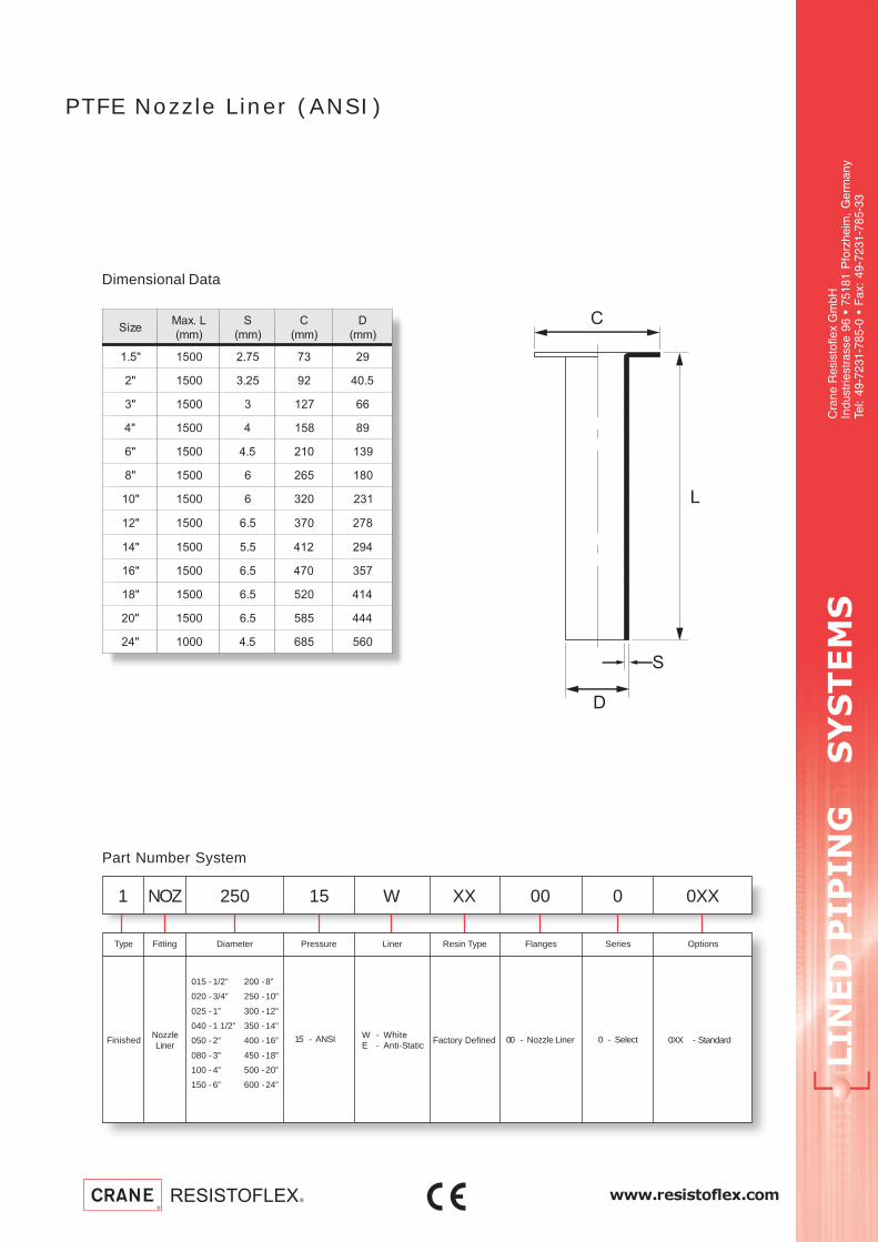
www.resistoflex.com
LIN
ED
P
IP
IN
G S
YS
TE
MS
Cra
ne R
esis
tofle
x G
mbH
Indu
strie
stra
sse
96 •
751
81 P
forz
heim
, G
erm
any
Tel:
49-7
231-
785-
0 •
Fax
: 49
-723
1-78
5-33
PTFE Nozzle Liner (ANSI)
Dimensional Data
Part Number System
FinishedNozzleLiner
15 - ANSI 00 - Nozzle LinerW - WhiteE - Anti-Static
Factory Defined 0XX - Standard
200 -8”
250 -10”
300 -12”
350 -14”
400 -16”
450 -18”
500 -20”
600 -24”
015 - 1/2”
020 - 3/4”
025 - 1”
040 - 1 1/2”
050 - 2”
080 - 3”
100 - 4”
150 - 6”
0 - Select
Diameter Pressure FlangesFittingType Liner Resin Type OptionsSeries
1 NOZ 250 15 W 00 0XXXX 0
eziSL.xaM
)mm(
S
)mm(
C
)mm(
D
)mm(
"5.1 0051 57.2 37 92
"2 0051 52.3 29 5.04
"3 0051 3 721 66
"4 0051 4 851 98
"6 0051 5.4 012 931
"8 0051 6 562 081
"01 0051 6 023 132
"21 0051 5.6 073 872
"41 0051 5.5 214 492
"61 0051 5.6 074 753
"81 0051 5.6 025 414
"02 0051 5.6 585 444
"42 0001 5.4 586 065

LIN
ED
P
IP
IN
G S
YS
TE
MS
Cra
ne R
esis
tofle
x G
mbH
Indu
strie
stra
sse
96 •
751
81 P
forz
heim
, G
erm
any
Tel:
49-7
231-
785-
0 •
Fax
: 49
-723
1-78
5-33
www.resistoflex.com
seireSeulaV seireStceleS snoitpO
051ssalC 051ssalCgnirutcafunamtceffayamnoitcelesnoitpO
dnaecirprofyrotcaftlusnoC.emitdael
.yreviled
"1
"52.1
"5.1
"2
"5,2
"3
"4
"6
"8
)skeeW2-1(emiTdaeL&ecirPtseB 032tamuucaVlluF OC
)skeeW6-4(emiTdaeLregnoL .pmeTdetavelEtaecnatsiseRmuucaVdecudeR
tseuqeRnopUyrevileDdnaecirP detaRmuucaV-noN
PTFE Lined Dip Pipe
CE, PED Cat. III (>025)
TEFLON® by DuPontD
N
PN
25
Form No. TDS-EUR-ANS-DPT-0204
Sta
inle
ss S
teel
Hou
sing
Con
duct
ive
Line
r
Use
in V
esse
ls w
ith A
gita
tors
Spe
cial
Pai
nt
PT
FE
Sol
id N
ozzl
e
Ear
thin
g S
tuds
Vac
uum
Res
ista
nce

www.resistoflex.com
LIN
ED
P
IP
IN
G S
YS
TE
MS
Cra
ne R
esis
tofle
x G
mbH
Indu
strie
stra
sse
96 •
751
81 P
forz
heim
, G
erm
any
Tel:
49-7
231-
785-
0 •
Fax
: 49
-723
1-78
5-33
PTFE Lined Dip Pipe
Fabricated Steel
Dimensional Data per PN 10
Part Number System
1 TAN 100 15 W 00 00XXXX
Finished DipPipe
Diameter Pressure FlangesFittingTyp
00W - WhiteE - Anti-Static
Liner PTFE Type
Factory Defined
Options
00XX - Standard0052 - Earthing Stud0070 - Stainless Steel
Factory Defined
1ND
.aiDedistuO
llaWx
)mm(
epyT1L
+ mm52
2L
+ mm5
3d
)mm(
4d
)mm(
C
)mm(
S + %01
)mm(
thgieW
epiPfo
)m/gk(
"1 6,2x7,33 I 0003 051 93 32 86 7,2 6,2
"52.1 6,2x4,24 I 0002 051 94 5,03 87 3,3 3,3
"5.12,3x3,84 I 0062 051 55 5,53
882,3 4,4
6,5x3,84 II 0082 051 45 23 7,2 3,7
"25,4x3,06 I 0052 051 76 54
2013,3 9,7
0,8x3,06 II 0072 051 76 83 3,3 2,21
"5,2 0,4x1,67 I 0081 051 5,28 26 221 1,3 2,9
"3
5,4x9,88 I 0012 051 69 37
831
4,3 2,21
0,01x9,88 II 0032 051 69 26 4,3 3,22
2,41x9,88 III 0042 051 69 45 4,3 92
"4
0,5x3,411 I 0012 051 5,421 49
851
5 5,71
0,01x3,411 II 0022 051 5,421 48 5 7,92
0,61x3,411 III 0042 051 5,421 27 5 6,24
"63,6x3,861 I 0091 051 5,771 741
2125,4 8,03
0,8x3,861 II 0091 051 5,771 341 5,4 9,63
"8 3,6x1,912 I 0012 051 032 691 862 3,5 2,14
15 - Class 15030 - Class 300

LIN
ED
P
IP
IN
G S
YS
TE
MS
Cra
ne R
esis
tofle
x G
mbH
Indu
strie
stra
sse
96 •
751
81 P
forz
heim
, G
erm
any
Tel:
49-7
231-
785-
0 •
Fax
: 49
-723
1-78
5-33
www.resistoflex.com
seireSeulaV seireStceleS snoitpO
051ssalC 051ssalC
tceffayamnoitcelesnoitpO
tlusnoC.emitdaelgnirutcafunam
yrevileddnaecirprofyrotcaf
"1
"52.1
"5.1
"2
"5,2
"3
"4
"6
"8
)skeeW2-1(emiTdaeL&ecirPtseB 032tamuucaVlluF OC
)skeeW6-4(emiTdaeLregnoL .pmeTdetavelEtaecnatsiseRmuucaVdecudeR
tseuqeRnopUyrevileDdnaecirP detaRmuucaV-noN
PTFE Lined Sparger
CE, PED Cat. III (>025)
TEFLON® by DuPontD
N
Cla
ss 3
00 F
lang
e
Form No. TDS-EUR-ANS-SPT-0204
Sta
inle
ss S
teel
Hou
sing
Con
duct
ive
Line
r
Use
in V
esse
ls w
ith A
gita
tors
Spe
cial
Pai
nt
Ear
thin
g S
tuds
Vac
uum
Res
ista
nce
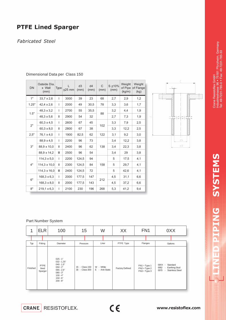
www.resistoflex.com
LIN
ED
P
IP
IN
G S
YS
TE
MS
Cra
ne R
esis
tofle
x G
mbH
Indu
strie
stra
sse
96 •
751
81 P
forz
heim
, G
erm
any
Tel:
49-7
231-
785-
0 •
Fax
: 49
-723
1-78
5-33
PTFE Lined Sparger
Fabricated Steel
Dimensional Data per Class 150
Part Number System
1 ELR 100 15 W FN1 0XXXX
FinishedPTFElined
Sparger
Diameter
15 - Class 15030 - Class 300
Pressure FlangesFittingTyp
W - WhiteE - Anti-Static
Liner PTFE Type
Factory Defined
Options
00XX - Standard0052 - Earthing Stud0070 - Stainless Steel
025 - 1”032 - 1,25”040 - 1,5”050 - 2”065 - 2,5”080 - 3”100 - 4”150 - 6”200 - 8”
FN1 = Type 1FN2 = Type 2FN3 = Type 3
ND
.aiDedistuO
llaWx
)mm(
epyTL
+ mm52
3d
)mm(
4d
)mm(
C
)mm(
S + %01
)mm(
thgieW
epiPfo
)m/gk(
thgieW
egnalFfo
)gk(
"1 6,2x7,33 I 0003 93 32 86 7,2 9,2 2,1
"52.1 6,2x4,24 I 0002 94 5,03 87 3,3 6,3 7,1
"5.12,3x3,84 I 0072 55 5,53
882,3 4,4 9,1
6,5x3,84 II 0092 45 23 7,2 3,7 9,1
"25,4x3,06 I 0062 76 54
2013,3 9,7 5,2
0,8x3,06 II 0082 76 83 3,3 2,21 5,2
"5,2 0,4x1,67 I 0091 5,28 26 221 1,3 2,9 0,3
"3
5,4x9,88 I 0022 69 37
831
4,3 2,21 8,3
0,01x9,88 II 0042 69 26 4,3 3,22 8,3
2,41x9,88 III 0052 69 45 4,3 92 8,3
"4
0,5x3,411 I 0022 5,421 49
851
5 5,71 1,4
0,01x3,411 II 0032 5,421 48 5 7,92 1,4
0,61x3,411 III 0042 5,421 27 5 6,24 1,4
"63,6x3,861 I 0002 5,771 741
2125,4 1,13 6,6
0,8x3,861 II 0002 5,771 341 5,4 2,73 6,6
"8 3,6x1,912 I 0012 032 691 862 3,5 2,14 4,9

LIN
ED
P
IP
IN
G S
YS
TE
MS
Cra
ne R
esis
tofle
x G
mbH
Indu
strie
stra
sse
96 •
751
81 P
forz
heim
, G
erm
any
Tel:
49-7
231-
785-
0 •
Fax
: 49
-723
1-78
5-33
www.resistoflex.com
)skeeW2-1(emiTdaeL&ecirPtseB
)skeeW6-4(emiTdaeLregnoL
tseuqeRnopUyrevileDdnaecirP
seireSeulaV seireStceleS .tpO
nielbaliavaton
seireSeulaV
531 3
541 6
561 8
091 8
012
6
6
042
31
8
11
542
8
8
8
062 11
072 8
572 9
592 9
003 9
033 31
593 31
044 71
054 31
094 61
PTFE Diaphragm
TEFLON® by DuPont
ma
x. O
uts
ide
Dia
me
ter
Form No. TDS-EU-ANS-DT-0104
Nu
mb
er
of
Co
nvo
lute
s
Whi
te L
iner
Bla
ck L
iner
Sta
ndar
d

www.resistoflex.com
LIN
ED
P
IP
IN
G S
YS
TE
MS
Cra
ne R
esis
tofle
x G
mbH
Indu
strie
stra
sse
96 •
751
81 P
forz
heim
, G
erm
any
Tel:
49-7
231-
785-
0 •
Fax
: 49
-723
1-78
5-33
PTFE Diaphragm
Dimensional data
Part Number System
1 MEM 245 08 W 00000000
Finished PTFEDiaphragm
max. Outside Diameter Number of Conv.FittingTyp
W - WhiteS - Black
Liner Options
135
145
165
190
210
240
245
260
270
275
295
300
330
395
440
450
490
00000000-Standard
03
06
08
09
11
13
16
17
.aiDedistuO.xam
%3-/%0+
)mm(
forebmuN
setulovnoC
1d
+ %5
)mm(
2d
+ %5
)mm(
S
+ %01
)mm(
531 3 25 52 5,1
541 6 56 52 5,1
561 8 99 04 5,1
091 8 69 83 5,1
012 6 26 71 8,1
012 6 57 71 8,1
042 31 011 41 3,2
042 8 541 04 3,2
042 11 002 66 3,2
542 8 69 04 3,2
542 8 041 55 3,2
542 8 341 54 3,2
062 11 002 37 5,2
072 8 231 04 5,2
572 9 061 45 5,2
592 9 061 55 5,2
003 9 561 55 5,2
033 31 702 55 5,2
593 31 802 45 7,2
044 71 852 45 3,3
054 31 082 25 3,3
094 61 033 05 3,3

LIN
ED
P
IP
IN
G S
YS
TE
MS
Cra
ne R
esis
tofle
x G
mbH
Indu
strie
stra
sse
96 •
751
81 P
forz
heim
, G
erm
any
Tel:
49-7
231-
785-
0 •
Fax
: 49
-723
1-78
5-33
www.resistoflex.comTDS-EU-ANS-G-0204
Bellow with
2 convolutions
Bellow with
5 convolutions
Bellow with
3 convolutions
Pressure-temperature-diagramms forPTFE-bellows withstandard wallthickness
Pressure-temperature-diagrammfor 3 convolutions
Pressure-temperature-diagrammfor 2 convolutions
Pressure-temperature-diagrammfor 5 convolutions

www.resistoflex.com
LIN
ED
P
IP
IN
G S
YS
TE
MS
Cra
ne R
esis
tofle
x G
mbH
Indu
strie
stra
sse
96 •
751
81 P
forz
heim
, G
erm
any
Tel:
49-7
231-
785-
0 •
Fax
: 49
-723
1-78
5-33
Pressure-temperature-diagrammfor SHD-bellow with 3 convolutionsfor non-shock working
Pressure-temperature-diagramms forPTFE-bellows withSHD wall thickness
Bellow with
3 convolutions
Bellow with
5 convolutions
Bellow with
2 convolutions
Pressure-temperature-diagramm for SHD-bellowwith 5 convolutions,for non-shock working
Pressure-temperature-diagrammfor SHD-bellow with 2 convolutionsfor non-shock working

LIN
ED
P
IP
IN
G S
YS
TE
MS
Cra
ne R
esis
tofle
x G
mbH
Indu
strie
stra
sse
96 •
751
81 P
forz
heim
, G
erm
any
Tel:
49-7
231-
785-
0 •
Fax
: 49
-723
1-78
5-33
www.resistoflex.comTDS-EU-ANS-H-0204
PTFE-Expansion Joint
2 Convolutions
Angular deflection approx. 7° max. Axial travel is based on installation withoutmisalignment or angular deflection.
The burst pressure is approx. 4 times the max. working pressure shown on thediagramm.
The figures stated are average values and apply to room temperature. Deviations dueto processing variations are possible.
For compression :Compression force Fc = C x S1/2
where C from table S = travel in mm
For extension:Expansion force Fw = W x S
where W from table S = travel in mm
Flanges up to DN 400 have 2 limit bolts, DN 450, 500 and 600 have 3.
ND
laixa
levart
.xam
(+ )mm
-ngilasim
tnem
.xam
)mm(
swolleb.ffe
-ssorc
noitces
mc( 2)
ecnatsisermuucav ecnatsisertnerehni
ta
01 4 aP
ta
C°.xam
C
.sserpmoc
)mm/N(
W
noisnetxe
)mm/N(
"5.0 5 2 01 1,0 002 62 42
"57.0 6 3 01 1,0 002 62 42
"1 6 3 01 1,0 002 62 42
"5.1 6 3 91 1,0 002 18 36
"2 6 3 03 1,0 002 041 09
"5.2 9 5 54 1,0 002 951 201
"3 9 5 07 1,0 002 071 021
"4 31 6 211 1,0 002 491 031
"5 31 6 661 1,0 051 032 831
"6 31 6 542 1,0 051 362 541
"8 31 6 0041,0 05
083 7512 051
"01 51 6 0667,0 54
212 6514,3 001
"21 02 01 0775,1 54
002 8517,6 001
"41 02 01 06215,1 54
152 5817,6 001
"61 52 01 00515,1 54
062 2917,6 001
"81 52 01 00024,3 54
583 0437 001
"02 52 01 0802 8 001 - -
"42 51 01 0023 7,8 001 - -

www.resistoflex.com
LIN
ED
P
IP
IN
G S
YS
TE
MS
Cra
ne R
esis
tofle
x G
mbH
Indu
strie
stra
sse
96 •
751
81 P
forz
heim
, G
erm
any
Tel:
49-7
231-
785-
0 •
Fax
: 49
-723
1-78
5-33
PTFE-Expansion Joint
3 ConvolutesND
laixa
levart
.xam
(+ )mm
-ngilasim
tnem
.xam
)mm(
swolleb.ffe
-ssorc
noitces
mc( 2)
ecnatsisermuucav ecnatsisertnerehni
ta
01 4 aP
ta
C°.xam
C
.sserpmoc
)mm/N(
W
noisnetxe
)mm/N(
"5.0 01 4 01 1,0 002 52 12
"57.0 21 5 01 1,0 002 52 12
"1 31 6 01 1,0 002 52 12
"5.1 31 6 91 1,0 002 36 15
"2 51 9 03 1,0 002 18 46
"5.2 91 9 54 1,0 002 421 48
"3 52 31 07 1,0 002 551 001
"4 52 31 211 1,0 002 571 401
"5 52 41 661 1,0 051 791 501
"6 82 41 542 1,0 051 022 801
"8 82 41 0041,0 05
462 092 051
"01 03 41 0667,0 54
091 394,3 001
"21 03 51 0775,1 54
081 597,6 001
"41 23 81 06215,1 54
732 0117,6 001
"61 53 02 00515,1 54
452 0017,6 001
"81 03 02 00024,3 54
– –7 001
"02 03 52 0802 8 001 – –
"42 52 02 0023 7,8 001 – –
Angular deflection approx. 14° max. Axial travel is based on installation withoutmisalignment or angular deflection.
The burst pressure is approx. 4 times the max. working pressure shown on thediagramm.
The figures stated are average values and apply to room temperature. Deviations dueto processing variations are possible.
For compression :Compression force Fc = C x S1/2
where C from table S = travel in mm
For extension:Expansion force Fw = W x S
where W from table S = travel in mm
Flanges up to DN 400 have 2 limit bolts, DN 450, 500 and 600 have 3.

LIN
ED
P
IP
IN
G S
YS
TE
MS
Cra
ne R
esis
tofle
x G
mbH
Indu
strie
stra
sse
96 •
751
81 P
forz
heim
, G
erm
any
Tel:
49-7
231-
785-
0 •
Fax
: 49
-723
1-78
5-33
www.resistoflex.comTDS-EU-ANS-I-0204
PTFE-Expansion Joint
5 Convolutions
Calculation of the forces for:
Compression of the bellow:force Fc = C x S1/2
with C from table S = travel in mm.
Extension of the bellow:force Fw = W x S
with W from table S = travel in mm.
Please notice:
- Curves and chart are only valid at neutral length and with limit bolts in place.- The max. angular deflection is approx. 20°.- Above mentioned travel, misalignment or angular deflectio are alternatives, i.e. the
percentage values are not allowed to exceed 100 % when added together.- Burst pressure is minimum 4x the indicated in the chart. Compared with the
pressure curves of the 2- and 3-convolute bellows, it is here much lowerbecause of the risk of buckling.
- The figures stated are average values and apply to room temperature. Deviationsdue to processing variations are possible.
- For abrasive applications the bellows (on request) can be equipped with a PTFE-nozzle liner, flared on one side. Movements are then restricted.
Savety instructions:
- Follow install. instructions.- Do not exceed pressure / temperature rating shown in the appropriate bellows
chart.- Safeguard the units in hazardous service.- Leave limit bolts in. Severe damage can result if they are removed or altered.- Remove the flange covers only when ready to install the bellow- Insure that sealing faces are clean, smooth and parallel.- While installing the flanges, make sure the bolts do not jut out from the flange
backside to the bellow.- Improperly installation or beyond the pressure / temperature rating may result in
property damage or personal injury.
ND
laixa
levart
.xam
(+ )mm
-ngilasim
tnem
.xam
)mm(
swolleb.ffe
-ssorc
noitces
mc( 2)
ecnatsisertnerehni
C
.sserpmoc
)mm/N(
W
noisnetxe
)mm/N(
"5.0 01 8 01 32 02
"57.0 21 01 01 32 02
"1 31 21 01 32 02
"5.1 91 21 91 55 04
"2 52 21 03 79 34
"5.2 52 31 54 201 65
"3 52 61 07 411 26
"4 23 61 211 721 76
"5 23 61 661 931 86
"6 23 61 542 051 86
"8 23 61 004 771 86
"01 23 61 066 051 86
"21 53 81 077 551 87
"41 53 81 0621 012 56
"61 04 52 0051 002 76
"02 04 52 0802 502 56

www.resistoflex.com
LIN
ED
P
IP
IN
G S
YS
TE
MS
Cra
ne R
esis
tofle
x G
mbH
Indu
strie
stra
sse
96 •
751
81 P
forz
heim
, G
erm
any
Tel:
49-7
231-
785-
0 •
Fax
: 49
-723
1-78
5-33
PTFE-SHD-Expansion Joint2 convolutions
For compression forces:Compression force Fc = C x S
with C from table, S = travel in mm.
For extension forces:Extension force Fw = W x S
with W from table, S = travel in mm.
Please notice:
- Curves and chart are only valid at neutral length and with limit bolts in place.- The max. angular deflection is approx. 5°.- Above mentioned travel, misalignment or angular deflection are alternatives, i.e.
the percentage values are not allowed to exceed 100 % when added together.- Burst pressure is about 4x the indicated in the chart.- The figures stated are average values and apply to room temperature. Deviations
due to processing variations are possible.- For abrasive applications the bellows (on request) can be equipped with a PTFE-
nozzle liner, flared on one side. Movements are then restricted.
Savety instructions:
- Follow install. instructions.- Do not exceed pressure / temperature rating shown in the appropriate bellows
chart.- Safeguard the units in hazardous service.- Leave limit bolts in. Severe damage can result if they areremoved or altered.- Remove the flange covers only when ready to install the bellow- Insure that sealing faces are clean, smooth and parallel.- While installing the flanges, make sure the bolts do not jut out from the flange
backside to the bellow.- Improperly installation or beyond the pressure / temperature rating may result in
property damage or personal injury.
ND
laixa
levart
.xam
(+ )mm
-ngilasim
tnem
.xam
)mm(
swolleb.ffe
-ssorc
noitces
mc( 2)
ecnatsisertnerehni
C
.sserpmoc
)mm/N(
W
noisnetxe
)mm/N(
"5.0 6 2 01 081 141
"57.0 6 2 01 081 141
"1 6 5,2 01 081 141
"5.1 8 3 91 002 311
"2 9 4 03 062 061
"5.2 9 5,4 54 111 441
"3 01 5,5 07 662 003
"4 31 6 211 902 881
"5 61 7 661 121 231
"6 61 8 542 772 432
"8 81 8 004 992 812
"01 02 8 066 471 842
"21 02 9 077 003 152
"41 22 9 0621 421 773
"61 42 01 0051 836 365
atadmuucav
muucavllufrof)F°(erutarepmet.xam
ND "2-"5.0 "3-"5.2 "5-"4 "8-"6 "61-"01
F°/C° °084/°032 °084/°032 °084/°032 °093/°002 °053/°571

LIN
ED
P
IP
IN
G S
YS
TE
MS
Cra
ne R
esis
tofle
x G
mbH
Indu
strie
stra
sse
96 •
751
81 P
forz
heim
, G
erm
any
Tel:
49-7
231-
785-
0 •
Fax
: 49
-723
1-78
5-33
www.resistoflex.comTDS-EU-ANS-J-0204
PTFE-SHD-Expansion Joint3 convolutions
For compression forces:Compression force Fc = C x S
with C from table, S = travel in mm.
For extension forces:Extension force Fw = W x S
with W from table, S = travel in mm.
Please notice:
- Above shown curves and chart are only valid at neutral length and with limit boltsin place.
- The max. angular deflection is approx. 10°.- Above mentioned travel, misalignment or angular deflection are alternatives, i.e.
the percentage values are not allowed to exceed 100 % when added together.- Burst pressure is about 4x the indicated in the chart.- The figures stated are average values and apply to room temperature. Deviations
due to processing variations are possible.- For abrasive applications the bellows (on request) can be equipped with a PTFE-
nozzle liner, flared on one side. Movements are then restricted.
Savety instructions:
- Follow install. instructions.- Do not exceed pressure / temperature rating shown in the appropriate bellows
chart.- Safeguard the units in hazardous service.- Leave limit bolts in. Severe damage can result if they are removed or altered.- Remove the flange covers only when ready to install the bellow- Insure that sealing faces are clean, smooth and parallel.- While installing the flanges, make sure the bolts do not jut out from the flange
backside to the bellow.- Improperly installation or beyond the pressure / temperature rating may result in
property damage or personal injury.
ND
laixa
levart
.xam
(+ )mm
-ngilasim
tnem
.xam
)mm(
swolleb.ffe
-ssorc
noitces
mc( 2)
ecnatsisertnerehni
C
.sserpmoc
)mm/N(
W
noisnetxe
)mm/N(
"5.0 9 3 01 021 49
"57.0 9 4 01 021 49
"1 9 4 01 021 49
"5.1 31 6 91 331 57
"2 51 8 03 371 401
"5.2 51 9 54 47 69
"3 61 01 07 871 002
"4 02 21 211 041 521
"5 52 31 661 5,08 88
"6 52 41 542 581 651
"8 82 41 004 002 541
"01 03 41 066 611 561
"21 03 51 077 002 3,761
"41 53 51 0621 921 723
"61 53 51 0051 524 573
atadmuucav
muucavllufrof)F°(erutarepmet.xam
ND "2-"5.0 "3-"5.2 "5-"4 "8-"6 "61-"01
F°/C° °084/°032 °084/°032 °084/°032 °093/°002 °053/°571

www.resistoflex.com
LIN
ED
P
IP
IN
G S
YS
TE
MS
Cra
ne R
esis
tofle
x G
mbH
Indu
strie
stra
sse
96 •
751
81 P
forz
heim
, G
erm
any
Tel:
49-7
231-
785-
0 •
Fax
: 49
-723
1-78
5-33
For compression forces:Compression force Fc = C x S
with C from table, S = travel in mm.
For extension forces:Extension force Fw = W x S
with W from table, S = travel in mm.
Please notice:
- Above shown curves and chart are only valid at neutral length and with limit boltsin place.
- The max. angular deflection is approx. 15°.- Above mentioned travel, misalignment or angular deflection are alternatives, i.e.
the percentage values are not allowed to exceed 100 % when added together.- Burst pressure is about 4x the indicated in the chart.
Compared with the pressure curves of the 2- and 3-convolute bellows, it is heremuch lower because of the risk of buckling.
- The figures stated are average values and apply to room temperature. Deviationsdue to processing variations are possible.
- For abrasive applications the bellows (on request) can be equipped with a PTFE-nozzle liner, flared on one side. Movements are then restricted.
Savety instructions:
- Follow install. instructions.- Do not exceed pressure / temperature rating shown in the appropriate bellows
chart.- Safeguard the units in hazardous service.- Leave limit bolts in. Severe damage can result if they are removed or altered.- Remove the flange covers only when ready to install the bellow- Insure that sealing faces are clean, smooth and parallel.- While installing the flanges, make sure the bolts do not jut out from the flange
backside to the bellow.- Improperly installation or beyond the pressure / temperature rating may result in
property damage or personal injury.
PTFE-SHD-Expansion Joint5 convolutions
ND
laixa
levart
.xam
(+ )mm
-ngilasim
tnem
.xam
)mm(
swolleb.ffe
-ssorc
noitces
mc( 2)
ecnatsisertnerehni
C
.sserpmoc
)mm/N(
W
noisnetxe
)mm/N(
"5.0 21 5 01 84 83
"57.0 21 5 01 84 83
"1 21 8 01 84 83
"5.1 81 8 91 35 03
"2 22 01 03 96 34
"5.2 22 01 54 03 83
"3 32 41 07 17 08
"4 92 41 211 65 05
"5 53 41 661 23 53
"6 53 41 542 47 26
"8 04 51 004 08 85
"01 24 51 066 64 66
"21 24 61 077 08 76
"41 34 71 0621 101 621
"61 54 81 0051 071 051

LIN
ED
P
IP
IN
G S
YS
TE
MS
Cra
ne R
esis
tofle
x G
mbH
Indu
strie
stra
sse
96 •
751
81 P
forz
heim
, G
erm
any
Tel:
49-7
231-
785-
0 •
Fax
: 49
-723
1-78
5-33
www.resistoflex.comTDS-EU-ANS-K-0204
PTFE-Expansion-Jointwith SS Housing &Spacer Bead
ND
laixa
tnemevom
0001=n
(+ )mm
laretal
tnemevom
(+ )mm
ralugna
-evom
tnem
)drg(
noisrot
tM
)mNk(
wolleb.ffe
-ssorc
noitces
A
mc( 2)
gnirps
etar
laixa
)mm/N(
gnirps
etar
laretal
)mm/N(
gnirps
etar
ralugna
)drg/mN(
lanoisrot
sserts
)drg/mNk(
ecivresmuucav
ta
F°27
C°32
01( 5 )aP
ta
F°023
C°061
01( 5 )aP
52.15,4 3,2 02 - 02 062 601 3,1 2,0 51,0 3,0
9 5,9 13 - 02 031 41 7,0 1,0 51,0 3,0
5.15,5 6,2 91 1,0 6,03 272 331 1,2 3,0 51,0 3,0
11 5,01 13 1,0 6,03 631 61 1 1,0 51,0 3,0
"25,6 8,2 91 1,0 7,44 672 751 1,3 5,0 51,0 3,0
5,31 31 33 2,0 3,44 591 32 2,2 4,0 51,0 3,0
"5.25,8 3 02 2,0 1,76 432 302 4 1,1 51,0 3,0
61 21 92 3,0 4,76 371 43 3 8,0 51,0 3,0
"301 2,3 02 3,0 3,78 022 922 5 6,1 51,0 3,0
5,71 11 03 4,0 6,78 871 35 1,4 3,1 51,0 3,0
"401 3,2 61 7,0 531 563 967 31 6,5 51,0 3,0
02 9 82 7,0 531 381 69 5,6 8,2 51,0 3,0
"55,41 9,3 02 9,0 3,971 092 644 41 9,6 52,0 4,0
52 5,41 03 9,1 7,081 092 59 41 6,6 52,0 4,0
"651 9,3 71 8,2 7,062 065 219 93 22 52,0 4,0
03 5,51 03 8,2 7,062 082 711 02 11 52,0 4,0
"812 2,4 91 1,4 9,134 214 3211 84 04 53,0 5,0
93 5,71 03 5,6 1,434 533 191 04 13 53,0 5,0
"0122 3 61 5,6 666 525 4203 59 111 4,0 6,0
04 5,21 52 8,7 4,766 962 803 94 14 4,0 6,0
"2172 4,4 71 2,9 1,239 084 7302 121 801 5,0 57,0
74 41 52 21 1,239 253 634 98 08 5,0 57,0
"4103 5,4 71 11 2,9111 064 5022 931 041 5,0 57,0
64 5,11 32 51 2,9111 873 276 511 611 5,0 57,0
"6162 9,2 31 02 8,8441 317 1126 182 333 7,0 9,0
25 5,11 22 02 8,8441 753 977 141 761 7,0 9,0
"8153 5,4 51 52 9,0281 845 3463 272 673 7,0 9,0
56 5,71 42 83 3,3181 034 546 412 482 7,0 9,0
"0282 8,2 21 74 4,5322 559 29401 685 349 1 1
36 5,41 22 74 4,5322 524 329 162 914 1 1
"4253 4,3 21 84 9,0023 845 2846 484 029 1 1
36 11 71 84 9,0023 503 2111 962 115 1 1
Reduction factors for application pressure, temperature related, acc. to flange material 1E1:
Flange material to select according to service temperature.
λ α cδδ cλ cα cΤ
erutarepmetC° 02 001 051 002 032
F° 86 212 203 293 054
erusserp.lpparab 01 8 5,7 9,6 2,6
gisp 241 411 701 89 88

www.resistoflex.com
LIN
ED
P
IP
IN
G S
YS
TE
MS
Cra
ne R
esis
tofle
x G
mbH
Indu
strie
stra
sse
96 •
751
81 P
forz
heim
, G
erm
any
Tel:
49-7
231-
785-
0 •
Fax
: 49
-723
1-78
5-33
PTFE-Expansion-Jointwith SS Housing &Spacer BeadFlanges ANSI CL300
ND
laixa
tnemevom
0001=n
(+ )mm
laretal
tnemevom
(+ )mm
ralugna
-evom
tnem
)drg(
noisrot
tM
)mNk(
wolleb.ffe
-ssorc
noitces
A
mc( 2)
gnirps
etar
laixa
)mm/N(
gnirps
etar
laretal
)mm/N(
gnirps
etar
ralugna
)drg/mN(
lanoisrot
sserts
)drg/mNk(
ecivresmuucav
ta
F°27
C°32
01( 5 )aP
ta
F°023
C°061
01( 5 )aP
52.14 1,2 71 1,0 7,91 824 971 2,2 2,0 51,0 3,0
5,7 7 42 1,0 7,91 832 03 2,1 1,0 51,0 3,0
5.15 5,2 71 1,0 8,03 824 781 3,3 4,0 51,0 3,0
5,8 9 22 2,0 5,03 453 43 7,2 3,0 51,0 3,0
"25,7 9,3 91 2,0 3,44 753 141 4 7,0 51,0 3,0
21 21 52 3,0 2,44 093 34 5,4 6,0 51,0 3,0
"5.27 7,2 61 5,0 2,76 066 994 21 6,2 51,0 3,0
31 9 32 5,0 2,76 763 38 5,6 5,1 51,0 3,0
"38 9,2 61 8,0 8,78 047 985 71 6,4 51,0 3,0
5,41 5,9 32 8,0 8,78 214 301 6,9 6,2 51,0 3,0
"45,01 2,3 61 3,1 2,531 616 007 22 8,8 51,0 3,0
5,71 01 32 8,1 531 325 271 91 4,6 51,0 3,0
"501 3,2 41 9,1 7,081 527 3841 53 71 52,0 4,0
5,71 7 02 9,1 7,081 514 772 02 5,9 52,0 4,0
"631 4,3 51 1,3 2,062 098 0541 26 52 52,0 4,0
5,32 11 12 1,3 2,062 594 352 53 41 52,0 4,0
"851 5,2 31 4,5 634 058 6043 001 46 53,0 5,0
62 5,7 91 4,5 634 684 436 75 73 53,0 5,0
"015,71 5,2 31 11 276 579 8005 971 641 4,0 6,0
5,03 8 81 11 276 855 239 201 48 4,0 6,0
"2102 8,2 21 81 239 8811 6766 203 562 5,0 57,0
53 5,8 81 81 239 976 9421 371 151 5,0 57,0
"4112 7,2 21 22 6111 0911 6957 363 743 5,0 57,0
63 5,8 71 22 6111 086 4141 702 891 5,0 57,0
"6122 7,2 11 93 9341 5061 07311 536 276 7,0 9,0
44 11 81 93 9341 308 3241 813 633 7,0 9,0
"8152 5,3 11 35 0381 0051 6428 657 057 7,0 9,0
54 5,11 61 35 0381 438 7141 124 714 7,0 9,0
"0242 5,2 6,9 66 4522 3761 09861 0401 8421 1 1
84 01 61 66 4522 738 1112 025 426 1 1
"4242 2 1,8 79 0913 5761 47252 3841 7922 1 1
84 8 31 79 0913 838 1613 247 9411 1 1
Reduction factors for application pressure, temperature related, acc. to flange material 1E1:
Flange material to select according to service temperature.
λ α cδδ cλ cα cΤ
erutarepmetC° 02 001 051 002 032
F° 86 212 203 293 054
erusserp.lpparab 52 02 7,81 2,71 5,51
gisp 553 482 5,562 442 022

LIN
ED
P
IP
IN
G S
YS
TE
MS
Cra
ne R
esis
tofle
x G
mbH
Indu
strie
stra
sse
96 •
751
81 P
forz
heim
, G
erm
any
Tel:
49-7
231-
785-
0 •
Fax
: 49
-723
1-78
5-33
www.resistoflex.com
seireSeulaV seireStceleS snoitpO
nielbaliavaton
seireSeulaV
051ssalC
yamnoitcelesnoitpO
daelgnirutcafunamtceffa
rofyrotcaftlusnoC.emit
yrevileddnaecirp
"5.0
"57.0
"1
"5.1
"2
"5.2
"3
"4
"5
"6
"8
"01
"21
"41
"61
"81
"02
"42
)skeeW2-1(emiTdaeL&ecirPtseB 032tamuucaVlluF OC
)skeeW6-4(emiTdaeLregnoL .pmeTdetavelEtaecnatsiseRmuucaVdecudeR
tseuqeRnopUyrevileDdnaecirP detaRmuucaV-noN
2 Convoluted PTFE Expansion Jointswith Reinforcing Rings
DN
Fla
nges
of
1.45
41
Con
duct
ive
Line
r
TDS-EU-ANS-E2T-SD-0204
Rei
nfor
cing
Rin
g H
aste
lloy
Fla
nges
of
1.00
38S
tand
ard
Lim
it B
olt
Inox
A2

www.resistoflex.com
LIN
ED
P
IP
IN
G S
YS
TE
MS
Cra
ne R
esis
tofle
x G
mbH
Indu
strie
stra
sse
96 •
751
81 P
forz
heim
, G
erm
any
Tel:
49-7
231-
785-
0 •
Fax
: 49
-723
1-78
5-33
2 Convoluted PTFE Expansion Jointswith Reinforcing Rings
Part Number System
1 K2W 250 15 W SS 00XXP1
Finished
ExpansionJointwith 2
Convolutes
Diameter
15 - ANSI 150
Pressure FlangesFittingType
SSW - WhiteE - Anti-Static
Liner Resin Type
Paste Standard
Options
0017 - Standard 1.00380018 - Flanges 1.4541
Dimensional Data
ND
L
+ %2
)mm(
daerhT C
)mm(
S
+ %01
)mm(
1d
+ %5
)mm(
3d
+ %5
)mm(
thgieW
)gk.ac(
"5.0 53 "2/1x4 53 3 42 34 6,1
"57.0 53 "2/1x4 34 3 42 34 6,1
"1 53 "2/1x4 15 3 42 34 6,1
"5.1 53 "2/1x4 37 3 63 75 5,2
"2 04 "8/5x4 29 3 05 57 6,3
"5.2 75 "8/5x4 501 3 06 19 4,4
"3 75 "8/5x4 721 5,3 67 401 2,5
"4 76 "8/5x8 851 4 001 431 9,6
"5 38 "4/3x8 681 52,4 221 361 2,11
"6 57 "4/3x8 612 5,4 051 881 3,21
"8 201 "4/3x8 072 52,5 402 052 02
"01 041 "8/7x21 423 52,5 552 523 62
"21 051 "8/7x21 183 5,5 082 543 33
"41 061 "1x21 214 6 053 834 75
"61 871 "1x61 074 5,6 093 264 27
"81 581 "8/11x61 435 5,6 524 515 97
"02 032 "8/11x02 585 5,6 074 555 38
"42 061 "4/11x02 296 5 575 566 801
015 - 1/2”
020 - 3/4”
025 - 1”
040 - 1 1/2”
050 - 2”
080 - 3”
100 - 4”
150 - 6”
200 - 8”
250 - 10”
300 - 12”
350 - 14”
400 - 16”
450 - 18”
500 - 20”
600 - 24”

LIN
ED
P
IP
IN
G S
YS
TE
MS
Cra
ne R
esis
tofle
x G
mbH
Indu
strie
stra
sse
96 •
751
81 P
forz
heim
, G
erm
any
Tel:
49-7
231-
785-
0 •
Fax
: 49
-723
1-78
5-33
www.resistoflex.com
seireSeulaV seireStceleS snoitpO
nielbaliavaton
seireSeulaV
051ssalC
yamnoitcelesnoitpO
daelgnirutcafunamtceffa
rofyrotcaftlusnoC.emit
yrevileddnaecirp
"5.0
"57.0
"1
"5.1
"2
"5.2
"3
"4
"5
"6
"8
"01
"21
"41
"61
"81
"02
"42
)skeeW2-1(emiTdaeL&ecirPtseB 032tamuucaVlluF OC
)skeeW6-4(emiTdaeLregnoL .pmeTdetavelEtaecnatsiseRmuucaVdecudeR
tseuqeRnopUyrevileDdnaecirP detaRmuucaV-noN
3 Convoluted PTFE Expansion Jointswith Reinforcing Rings
DN
Fla
nges
of
1.4
541
Con
duct
ive
Line
r
TDS-EU-ANS-E3T-SD-0204
Fla
nges
of
1.0
038
Sta
ndar
d
Lim
it B
olt
Inox
A2
Rei
nfor
cing
Rin
g H
aste
lloy
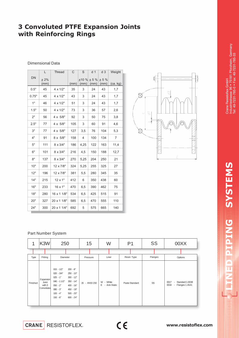
www.resistoflex.com
LIN
ED
P
IP
IN
G S
YS
TE
MS
Cra
ne R
esis
tofle
x G
mbH
Indu
strie
stra
sse
96 •
751
81 P
forz
heim
, G
erm
any
Tel:
49-7
231-
785-
0 •
Fax
: 49
-723
1-78
5-33
3 Convoluted PTFE Expansion Jointswith Reinforcing Rings
Part Number System
1 K3W 250 15 W SS 00XXP1
Finished
ExpansionJointwith 3
Convolutes
Diameter
15 - ANSI 150
Pressure FlangesFittingType
SSW - WhiteE - Anti-Static
Liner Resin Type
Paste Standard
Options
0017 - Standard 1.00380018 - Flanges 1.4541
Dimensional Data
ND
L
+ %2
)mm(
daerhT C
)mm(
S
+ %01
)mm(
1d
+ %5
)mm(
3d
+ %5
)mm(
thgieW
)gk.ac(
"5.0 54 "2/1x4 53 3 42 34 7,1
"57.0 54 "2/1x4 34 3 42 34 7,1
"1 64 "2/1x4 15 3 42 34 7,1
"5.1 05 "2/1x4 37 3 63 75 6,2
"2 65 "8/5x4 29 3 05 57 8,3
"5.2 77 "8/5x4 501 3 06 19 6,4
"3 77 "8/5x4 721 5,3 67 401 3,5
"4 19 "8/5x8 851 4 001 431 7
"5 111 "4/3x8 681 52,4 221 361 4,11
"6 101 "4/3x8 612 5,4 051 881 7,21
"8 731 "4/3x8 072 52,5 402 052 12
"01 002 "8/7x21 423 52,5 552 523 72
"21 691 "8/7x21 183 5,5 082 543 53
"41 512 "1x21 214 6 053 834 06
"61 332 "1x61 074 5,6 093 264 57
"81 082 "8/11x61 435 5,6 524 515 19
"02 723 "8/11x02 585 5,6 074 555 011
"42 003 "4/11x02 296 5 575 566 041
015 -1/2”
020 -3/4”
025 -1”
040 -1 1/2”
050 -2”
080 -3”
100 -4”
150 -6”
200 -8”
250 -10”
300 -12”
350 -14”
400 -16”
450 -18”
500 -20”
600 -24”

LIN
ED
P
IP
IN
G S
YS
TE
MS
Cra
ne R
esis
tofle
x G
mbH
Indu
strie
stra
sse
96 •
751
81 P
forz
heim
, G
erm
any
Tel:
49-7
231-
785-
0 •
Fax
: 49
-723
1-78
5-33
www.resistoflex.com
seireSeulaV seireStceleS snoitpO
nielbaliavaton
seireSeulaV
051ssalC
yamnoitcelesnoitpO
daelgnirutcafunamtceffa
rofyrotcaftlusnoC.emit
yrevileddnaecirp
"5.0
"57.0
"1
"5.1
"2
"5.2
"3
"4
"5
"6
"8
"01
"21
"41
"61
)skeeW2-1(emiTdaeL&ecirPtseB 032tamuucaVlluF OC
)skeeW6-4(emiTdaeLregnoL .pmeTdetavelEtaecnatsiseRmuucaVdecudeR
tseuqeRnopUyrevileDdnaecirP detaRmuucaV-noN
5 Convoluted PTFE Expansion Jointswith Reinforcing Rings
DN
Fla
nges
of
1.4
541
Con
duct
ive
Line
r
TDS-EU-ANS-E5T-SD-0204
Fla
nges
of
1.0
038
Sta
ndar
d
Lim
it B
olt
Inox
A2
Rei
nfor
cing
Rin
g H
aste
lloy
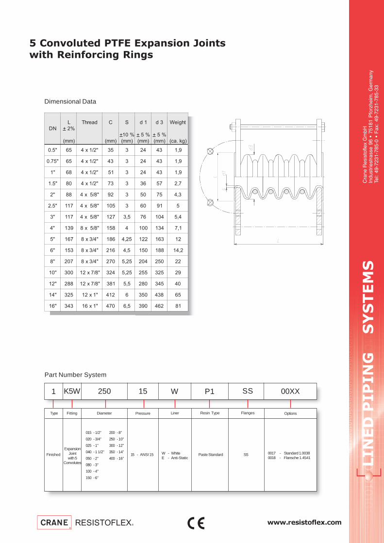
www.resistoflex.com
LIN
ED
P
IP
IN
G S
YS
TE
MS
Cra
ne R
esis
tofle
x G
mbH
Indu
strie
stra
sse
96 •
751
81 P
forz
heim
, G
erm
any
Tel:
49-7
231-
785-
0 •
Fax
: 49
-723
1-78
5-33
5 Convoluted PTFE Expansion Jointswith Reinforcing Rings
Part Number System
1 K5W 250 15 W SS 00XXP1
Finished
ExpansionJointwith 5
Convolutes
Diameter
15 - ANSI 15
Pressure FlangesFittingType
SSW - WhiteE - Anti-Static
Liner Resin Type
Paste Standard
Options
0017 - Standard 1.00380018 - Flansche 1.4541
Dimensional Data
ND
L
+ %2
)mm(
daerhT C
)mm(
S
+ %01
)mm(
1d
+ %5
)mm(
3d
+ %5
)mm(
thgieW
)gk.ac(
"5.0 56 "2/1x4 53 3 42 34 9,1
"57.0 56 "2/1x4 34 3 42 34 9,1
"1 86 "2/1x4 15 3 42 34 9,1
"5.1 08 "2/1x4 37 3 63 75 7,2
"2 88 "8/5x4 29 3 05 57 3,4
"5.2 711 "8/5x4 501 3 06 19 5
"3 711 "8/5x4 721 5,3 67 401 4,5
"4 931 "8/5x8 851 4 001 431 1,7
"5 761 "4/3x8 681 52,4 221 361 21
"6 351 "4/3x8 612 5,4 051 881 2,41
"8 702 "4/3x8 072 52,5 402 052 22
"01 003 "8/7x21 423 52,5 552 523 92
"21 882 "8/7x21 183 5,5 082 543 04
"41 523 "1x21 214 6 053 834 56
"61 343 "1x61 074 5,6 093 264 18
015 -1/2”
020 -3/4”
025 -1”
040 -1 1/2”
050 -2”
080 -3”
100 -4”
150 -6”
200 -8”
250 -10”
300 -12”
350 -14”
400 -16”
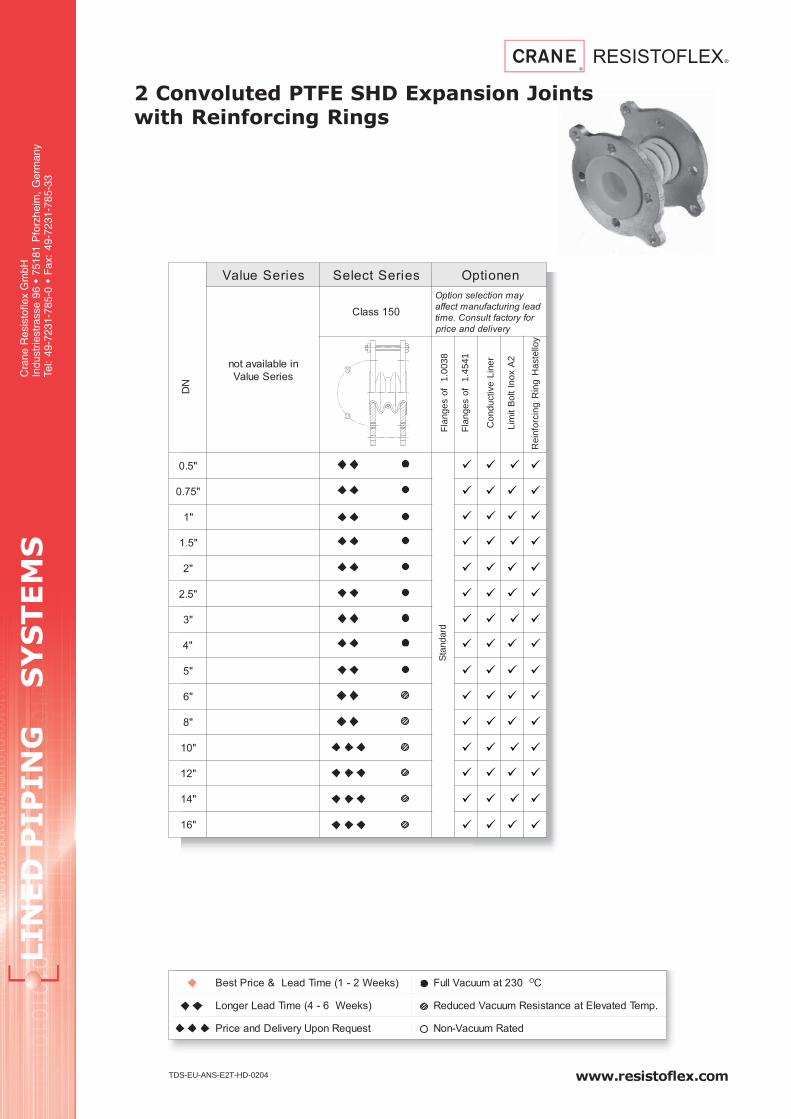
LIN
ED
P
IP
IN
G S
YS
TE
MS
Cra
ne R
esis
tofle
x G
mbH
Indu
strie
stra
sse
96 •
751
81 P
forz
heim
, G
erm
any
Tel:
49-7
231-
785-
0 •
Fax
: 49
-723
1-78
5-33
www.resistoflex.com
seireSeulaV seireStceleS nenoitpO
nielbaliavaton
seireSeulaV
051ssalC
yamnoitcelesnoitpO
daelgnirutcafunamtceffa
rofyrotcaftlusnoC.emit
yrevileddnaecirp
"5.0
"57.0
"1
"5.1
"2
"5.2
"3
"4
"5
"6
"8
"01
"21
"41
"61
)skeeW2-1(emiTdaeL&ecirPtseB 032tamuucaVlluF OC
)skeeW6-4(emiTdaeLregnoL .pmeTdetavelEtaecnatsiseRmuucaVdecudeR
tseuqeRnopUyrevileDdnaecirP detaRmuucaV-noN
2 Convoluted PTFE SHD Expansion Jointswith Reinforcing Rings
DN
Fla
nges
of
1.4
541
Con
duct
ive
Line
r
TDS-EU-ANS-E2T-HD-0204
Fla
nges
of
1.0
038
Sta
ndar
d
Lim
it B
olt
Inox
A2
Rei
nfor
cing
Rin
g H
aste
lloy

www.resistoflex.com
LIN
ED
P
IP
IN
G S
YS
TE
MS
Cra
ne R
esis
tofle
x G
mbH
Indu
strie
stra
sse
96 •
751
81 P
forz
heim
, G
erm
any
Tel:
49-7
231-
785-
0 •
Fax
: 49
-723
1-78
5-33
2 Convoluted PTFE SHD Expansion Jointswith Reinforcing Rings
Part Number System
1 K2W 250 15 W SS 00XXP3
Finished
SHDExpansion
Jointwith 2
Convolutes
Diameter
15 - ANSI 150
Pressure FlangesFittingType
SSW - WhiteE - Anti-Static
Liner Resin Type
Paste SHD
Options
0017 - Standard 1.00380018 - Flanges 1.4541
Dimensional Data
ND
L
+ %3
)mm(
daerhT
1052NID
C
)mm(
S
.nim
)mm(
S
.xam
)mm(
1d
+ %5
)mm(
3d
+ %5
)mm(
thgieW
)gk.ac(
"5.0 63 "2/1x4 53 2 5 32 14 4,1
"57.0 63 "2/1x4 34 2 5 32 24 5,1
"1 63 "2/1x4 15 52,2 5 42 34 56,1
"5.1 93 "2/1x4 37 52,2 5 63 75 55,2
"2 74 "8/5x4 29 52,2 5 05 57 7,3
"5.2 15 "8/5x4 501 52,2 5 06 19 5,4
"3 25 "8/5x4 721 57,2 6 67 401 5,5
"4 46 "8/5x8 851 57,2 6 001 431 4,7
"5 77 "4/3x8 681 57,2 6 221 361 5,11
"6 27 "4/3x8 612 3 57,6 051 881 31
"8 29 "4/3x8 072 5,3 57,6 402 052 5,12
"01 531 "8/7x21 423 52,3 7 552 523 62
"21 531 "8/7x21 183 4 5,7 082 543 53
"41 051 "1x21 214 5,4 9 533 534 65
"61 651 "1x61 074 5 01 093 264 47
015 -1/2”
020 -3/4”
025 -1”
040 -1 1/2”
050 -2”
080 -3”
100 -4”
150 -6”
200 -8”
250 -10”
300 -12”
350 -14”
400 -16”

LIN
ED
P
IP
IN
G S
YS
TE
MS
Cra
ne R
esis
tofle
x G
mbH
Indu
strie
stra
sse
96 •
751
81 P
forz
heim
, G
erm
any
Tel:
49-7
231-
785-
0 •
Fax
: 49
-723
1-78
5-33
www.resistoflex.com
seireSeulaV seireStceleS nenoitpO
nielbaliavaton
seireSeulaV
051ssalC
yamnoitcelesnoitpO
daelgnirutcafunamtceffa
rofyrotcaftlusnoC.emit
yrevileddnaecirp
"5.0
"57.0
"1
"5.1
"2
"5.2
"3
"4
"5
"6
"8
"01
"21
"41
"61
)skeeW2-1(emiTdaeL&ecirPtseB 032tamuucaVlluF OC
)skeeW6-4(emiTdaeLregnoL .pmeTdetavelEtaecnatsiseRmuucaVdecudeR
tseuqeRnopUyrevileDdnaecirP detaRmuucaV-noN
3 Convoluted PTFE SHD Expansion Jointswith Reinforcing Rings
DN
Fla
nges
of
1.4
541
Con
duct
ive
Line
r
TDS-EU-ANS-E3T-HD-0204
Fla
nges
of
1.0
038
Sta
ndar
d
Lim
it B
olt
Inox
A2
Rei
nfor
cing
Rin
g H
aste
lloy

www.resistoflex.com
LIN
ED
P
IP
IN
G S
YS
TE
MS
Cra
ne R
esis
tofle
x G
mbH
Indu
strie
stra
sse
96 •
751
81 P
forz
heim
, G
erm
any
Tel:
49-7
231-
785-
0 •
Fax
: 49
-723
1-78
5-33
3 Convoluted PTFE SHD Expansion Jointswith Reinforcing Rings
Part Number System
1 K3W 250 15 W SS 00XXP3
Finished
ExpansionJointwith 3
Convolutes
Diameter
15 - ANSI 150
Pressure FlangesFittingType
SSW - WhiteE - Anti-Static
Liner Resin Type
Paste SHD
Options
0017 - Standard 1.00380018 - Flanges 1.4541
Dimensional Data
015 -1/2”
020 -3/4”
025 -1”
040 -1 1/2”
050 -2”
080 -3”
100 -4”
150 -6”
200 -8”
250 -10”
300 -12”
350 -14”
400 -16”
ND
L
+ %3
)mm(
daerhT
1052NID
C
)mm(
S
.nim
)mm(
S
.xam
)mm(
1d
+ %5
)mm(
3d
+ %5
)mm(
thgieW
)gk.ac(
"5.0 45 "2/1x4 53 2 5 32 14 5,1
"57.0 45 "2/1x4 34 2 5 32 24 6,1
"1 45 "2/1x4 15 52,2 5 42 34 7,1
"5.1 85 "2/1x4 37 52,2 5 63 75 6,2
"2 96 "8/5x4 29 52,2 5 05 57 8,3
"5.2 77 "8/5x4 501 52,2 5 06 19 6,4
"3 87 "8/5x4 721 57,2 6 67 401 6,5
"4 89 "8/5x8 851 57,2 6 001 431 5,7
"5 711 "4/3x8 681 57,2 6 221 361 6,11
"6 011 "4/3x8 612 3 57,6 051 881 2,31
"8 041 "4/3x8 072 5,3 57,6 402 052 22
"01 091 "8/7x21 423 52,3 7 552 523 5,62
"21 891 "8/7x21 183 4 5,7 082 543 63
"41 491 "1x21 214 5,4 9 533 534 85
"61 332 "1x61 074 5 01 093 264 67

LIN
ED
P
IP
IN
G S
YS
TE
MS
Cra
ne R
esis
tofle
x G
mbH
Indu
strie
stra
sse
96 •
751
81 P
forz
heim
, G
erm
any
Tel:
49-7
231-
785-
0 •
Fax
: 49
-723
1-78
5-33
www.resistoflex.com
seireSeulaV seireStceleS nenoitpO
nielbaliavaton
seireSeulaV
051ssalC
yamnoitcelesnoitpO
daelgnirutcafunamtceffa
rofyrotcaftlusnoC.emit
yrevileddnaecirp
"5.0
"57.0
"1
"5.1
"2
"5.2
"3
"4
"5
"6
"8
"01
"21
"41
"61
)skeeW2-1(emiTdaeL&ecirPtseB 032tamuucaVlluF OC
)skeeW6-4(emiTdaeLregnoL .pmeTdetavelEtaecnatsiseRmuucaVdecudeR
tseuqeRnopUyrevileDdnaecirP detaRmuucaV-noN
5 Convoluted SHD PTFE Expansion Jointswith Reinforcing Rings
DN
Fla
nges
of
1.4
541
Con
duct
ive
Line
r
TDS-EU-ANS-E5T-HD-0204
Fla
nges
of
1.0
038
Sta
ndar
d
Lim
it B
olt
Inox
A2
Rei
nfor
cing
Rin
g H
aste
lloy

www.resistoflex.com
LIN
ED
P
IP
IN
G S
YS
TE
MS
Cra
ne R
esis
tofle
x G
mbH
Indu
strie
stra
sse
96 •
751
81 P
forz
heim
, G
erm
any
Tel:
49-7
231-
785-
0 •
Fax
: 49
-723
1-78
5-33
5 Convoluted PTFE SHD Expansion Jointswith Reinforcing Rings
Part Number System
1 K5W 250 15 W SS 00XXP3
Finished
ExpansionJointwith 5
Convolutes
Diameter
15 - ANSI 15
Pressure FlangesFittingType
SSW - WhiteE - Anti-Static
Liner Resin Type
Paste SHD
Options
0017 - Standard 1.00380018 - Flansche 1.4541
Dimensional Data
015 -1/2”
020 -3/4”
025 -1”
040 -1 1/2”
050 -2”
080 -3”
100 -4”
150 -6”
200 -8”
250 -10”
300 -12”
350 -14”
400 -16”
ND
L
+ %3
)mm(
daerhT
1052NID
C
)mm(
S
.nim
)mm(
S
.xam
)mm(
1d
+ %5
)mm(
3d
+ %5
)mm(
thgieW
)gk.ac(
"5.0 78 "2/1x4 53 2 5 32 14 6,1
"57.0 78 "2/1x4 34 2 5 32 24 7,1
"1 78 "2/1x4 15 52,2 5 42 34 8,1
"5.1 49 "2/1x4 37 52,2 5 63 75 7,2
"2 211 "8/5x4 29 52,2 5 05 57 4
"5.2 421 "8/5x4 501 52,2 5 06 19 8,4
"3 621 "8/5x4 721 57,2 6 67 401 8,5
"4 751 "8/5x8 851 57,2 6 001 431 7,7
"5 781 "4/3x8 681 57,2 6 221 361 21
"6 671 "4/3x8 612 3 57,6 051 881 5,31
"8 322 "4/3x8 072 5,3 57,6 402 052 5,22
"01 013 "8/7x21 423 52,3 7 552 523 4,82
"21 813 "8/7x21 183 4 5,7 082 543 73
"41 413 "1x21 214 5,4 9 533 534 16
"61 573 "1x61 074 5 01 093 264 87

LIN
ED
P
IP
IN
G S
YS
TE
MS
Cra
ne R
esis
tofle
x G
mbH
Indu
strie
stra
sse
96 •
751
81 P
forz
heim
, G
erm
any
Tel:
49-7
231-
785-
0 •
Fax
: 49
-723
1-78
5-33
www.resistoflex.com
seireSeulaV seireStceleS
nielbaliavaton
seireSeulaV
051ssalC
tceffayamnoitcelesnoitpO
.emitdaelgnirutcafunam
dnaecirprofyrotcaftlusnoC
yreviled
"52.1
"5.1
"2
"5.2
"3
"4
"5
"6
)skeeW2-1(emiTdaeL&ecirPtseB 032tamuucaVlluF OC
)skeeW6-4(emiTdaeLregnoL .pmeTdetavelEtaecnatsiseRmuucaVdecudeR
tseuqeRnopUyrevileDdnaecirP detaRmuucaV-noN
PTFE-Expansion Jointswith SS Housing and Spacer Bead
TEFLON® by DuPontD
N
Fla
nges
1.4
541
Con
duct
ive
Line
r
TDS-EU-ANS-EST-1-6-0904
Bel
low
of 1
.454
1
Fla
nges
of
1.00
38S
tand
ard
DN 1.25” - 6”
Bel
low
of
Has
tello
y C
4
Cla
ss 3
00
Sta
ndar
d

www.resistoflex.com
LIN
ED
P
IP
IN
G S
YS
TE
MS
Cra
ne R
esis
tofle
x G
mbH
Indu
strie
stra
sse
96 •
751
81 P
forz
heim
, G
erm
any
Tel:
49-7
231-
785-
0 •
Fax
: 49
-723
1-78
5-33
PTFE-Expansion Jointswith SS Housing and Spacer Bead
Part Number System
1 EKS 100 15 W LLL1 XXXX
Finished
StainlessSteel
ExpansionJoint
Diameter
15 - ANSI 15030 - ANSI 300
Pressure FlangesFittingType
LL L1 - loose /loose - Length 1
LL L2 - loose /loose - Length 2
W - WhiteE - Anti-Static
Liner Resin Type
Factory Defined
Options
26 - Flanges 1.003827 - Flanges 1.4541
Dimensional Data per Class 150
DN 1.25” - 6”
032 - 1.25”
040 - 1.5”
050 - 2”
065 - 2.5”
080 - 3”
100 - 4”
125 - 5”
150 - 6”
200 - 8”
250 -10”
300 -12”
350 -14”
400 -16”
450 -18”
500 -20”
600 -24”
ND
L
%5+
%5,1-
)mm(
S
+ %01
)mm(
C
+ %5
)mm(
1d
+ %5
)mm(
3d
+ %5
)mm(
thgieW
)gk.ac(
52.1541 3 07 53 16 9,3
022 3 07 53 16 1,4
"5.1751 4 08 44 77 5,4
242 4 08 44 77 8,4
"2971 4 29 65 98 7,5
492 4 29 65 98 5,6
"5.2181 4 701 27 801 9,6
782 4 701 27 801 9,7
"3581 4 221 48 421 8
572 4 221 48 421 9
"4971 5,4 741 701 151 01
762 5,4 741 701 151 11
"5122 5,4 871 621 181 41
363 5,4 871 621 181 71
"6842 5 802 451 212 81
883 5 802 451 212 32
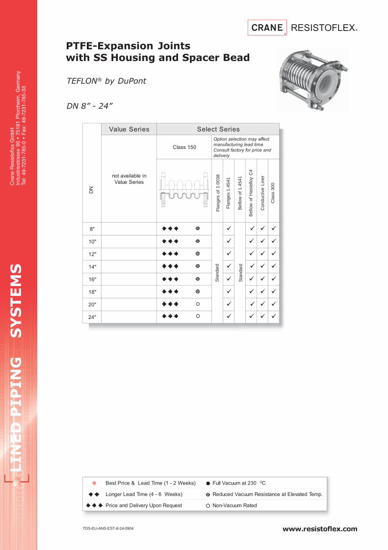
LIN
ED
P
IP
IN
G S
YS
TE
MS
Cra
ne R
esis
tofle
x G
mbH
Indu
strie
stra
sse
96 •
751
81 P
forz
heim
, G
erm
any
Tel:
49-7
231-
785-
0 •
Fax
: 49
-723
1-78
5-33
www.resistoflex.com
seireSeulaV seireStceleS
nielbaliavaton
seireSeulaV
051ssalC
tceffayamnoitcelesnoitpO
.emitdaelgnirutcafunam
dnaecirprofyrotcaftlusnoC
yreviled
"8
"01
"21
"41
"61
"81
"02
"42
)skeeW2-1(emiTdaeL&ecirPtseB 032tamuucaVlluF OC
)skeeW6-4(emiTdaeLregnoL .pmeTdetavelEtaecnatsiseRmuucaVdecudeR
tseuqeRnopUyrevileDdnaecirP detaRmuucaV-noN
PTFE-Expansion Jointswith SS Housing and Spacer Bead
TEFLON® by DuPontD
N
Fla
nges
1.4
541
Con
duct
ive
Line
r
TDS-EU-ANS-EST-8-24-0904
Bel
low
of 1
.454
1
Fla
nges
of
1.00
38S
tand
ard
DN 8” - 24”
Bel
low
of
Has
tello
y C
4
Cla
ss 3
00
Sta
ndar
d

www.resistoflex.com
LIN
ED
P
IP
IN
G S
YS
TE
MS
Cra
ne R
esis
tofle
x G
mbH
Indu
strie
stra
sse
96 •
751
81 P
forz
heim
, G
erm
any
Tel:
49-7
231-
785-
0 •
Fax
: 49
-723
1-78
5-33
PTFE-Expansion Jointswith SS Housing and Spacer Bead
Part Number System
1 EKS 250 15 W LLL1 XXXX
Finished
StainlessSteel
ExpansionJoint
Diameter
15 - ANSI 15030 - ANSI 300
Pressure FlangesFittingType
LL L1 - loose /loose - Length 1
LL L2 - loose /loose - Length 2
W - WhiteE - Anti-Static
Liner Resin Type
Factory Defined
Options
26 - Flanges 1.003827 - Flanges 1.4541
Dimensional Data per Class 150
DN 8” - 24”
032 - 1.25”
040 - 1.5”
050 - 2”
065 - 2.5”
080 - 3”
100 - 4”
125 - 5”
150 - 6”
200 - 8”
250 -10”
300 -12”
350 -14”
400 -16”
450 -18”
500 -20”
600 -24”
ND
L
%5+
%5,1-
)mm(
S
+ %01
)mm(
C
+ %5
)mm(
1d
+ %5
)mm(
3d
+ %5
)mm(
thgieW
)gk.ac(
"8642 5 852 402 562 52
814 5 852 402 562 33
"01142 5 023 852 423 23
093 5 023 852 423 83
"21782 6 073 603 673 04
924 6 073 603 673 15
"41692 52,6 014 733 804 65
704 52,6 014 733 804 66
"61882 52,6 564 783 164 47
234 52,6 564 783 164 58
"81923 52,6 025 834 615 58
635 52,6 025 834 615 311
"02013 52,6 075 984 075 401
015 52,6 075 984 075 921
"42433 5,4 076 495 876 621
284 5,4 076 495 876 441

LIN
ED
P
IP
IN
G S
YS
TE
MS
Cra
ne R
esis
tofle
x G
mbH
Indu
strie
stra
sse
96 •
751
81 P
forz
heim
, G
erm
any
Tel:
49-7
231-
785-
0 •
Fax
: 49
-723
1-78
5-33
www.resistoflex.com
seireSeulaV seireStceleS
nielbaliavaton
seireSeulaV
003ssalC
tceffayamnoitcelesnoitpO
.emitdaelgnirutcafunam
dnaecirprofyrotcaftlusnoC
yreviled
"52.1
"5.1
"2
"5.2
"3
"4
"5
"6
)skeeW2-1(emiTdaeL&ecirPtseB 032tamuucaVlluF OC
)skeeW6-4(emiTdaeLregnoL .pmeTdetavelEtaecnatsiseRmuucaVdecudeR
tseuqeRnopUyrevileDdnaecirP detaRmuucaV-noN
PTFE-Expansion Joints with SS Housingand Spacer Bead (ANSI Class 300)
TEFLON® by DuPontD
N
Fla
nges
1.4
541
Con
duct
ive
Line
r
TDS-EU-ANS-EST-CL3-1-6-0904
Bel
low
of 1
.454
1
Fla
nges
of
1.00
38S
tand
ard
DN 1.25” - 6”
Bel
low
of
Has
tello
y C
4
Cla
ss 1
50
Sta
ndar
d
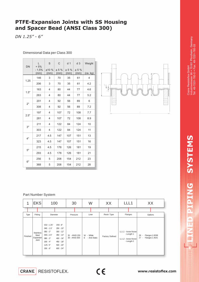
www.resistoflex.com
LIN
ED
P
IP
IN
G S
YS
TE
MS
Cra
ne R
esis
tofle
x G
mbH
Indu
strie
stra
sse
96 •
751
81 P
forz
heim
, G
erm
any
Tel:
49-7
231-
785-
0 •
Fax
: 49
-723
1-78
5-33
PTFE-Expansion Joints with SS Housingand Spacer Bead (ANSI Class 300)
Part Number System
1 EKS 100 30 W LLL1 XXXX
Finished
StainlessSteel
ExpansionJoint
Diameter
15 - ANSI 15030 - ANSI 300
Pressure FlangesFittingType
LL L1 - loose /loose - Length 1
LL L2 - loose /loose - Length 2
W - WhiteE - Anti-Static
Liner Resin Type
Factory Defined
Options
26 - Flanges 1.003827 - Flanges 1.4541
Dimensional Data per Class 300
DN 1.25” - 6”
032 - 1.25”
040 - 1.5”
050 - 2”
065 - 2.5”
080 - 3”
100 - 4”
125 - 5”
150 - 6”
200 - 8”
250 -10”
300 -12”
350 -14”
400 -16”
450 -18”
500 -20”
600 -24”
ND
L
%5+
%5,1-
)mm(
S
+ %01
)mm(
C
+ %5
)mm(
1d
+ %5
)mm(
3d
+ %5
)mm(
thgieW
)gk.ac(
52.1641 3 07 53 16 4
602 3 07 53 16 2.4
"5.1361 4 08 44 77 6.4
362 4 08 44 77 2.5
"2102 4 29 65 98 6
803 4 29 65 98 2.7
"5.2791 4 701 27 801 7.7
182 4 701 27 801 9.8
"3112 4 221 48 421 01
303 4 221 48 421 11
"4712 5.4 741 701 151 31
323 5.4 741 701 151 61
"5512 5.4 871 621 181 91
392 5.4 871 621 181 12
"6652 5 802 451 212 32
863 5 802 451 212 82
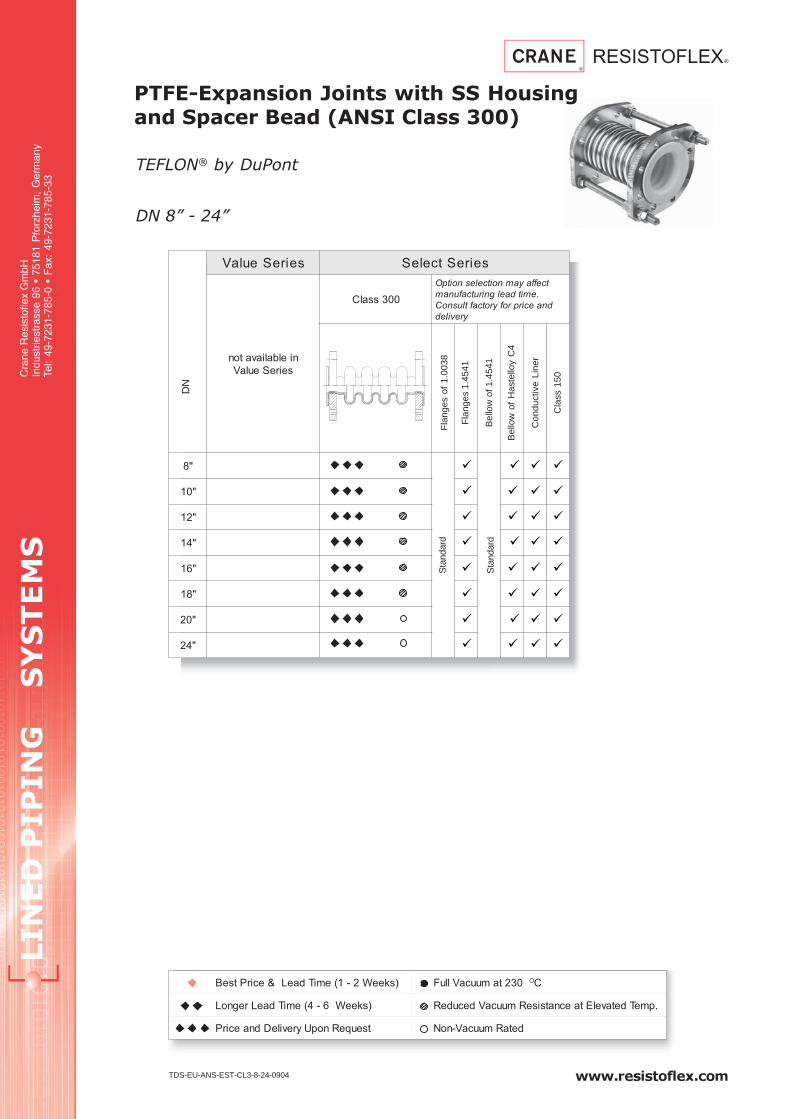
LIN
ED
P
IP
IN
G S
YS
TE
MS
Cra
ne R
esis
tofle
x G
mbH
Indu
strie
stra
sse
96 •
751
81 P
forz
heim
, G
erm
any
Tel:
49-7
231-
785-
0 •
Fax
: 49
-723
1-78
5-33
www.resistoflex.com
seireSeulaV seireStceleS
nielbaliavaton
seireSeulaV
003ssalC
tceffayamnoitcelesnoitpO
.emitdaelgnirutcafunam
dnaecirprofyrotcaftlusnoC
yreviled
"8
"01
"21
"41
"61
"81
"02
"42
)skeeW2-1(emiTdaeL&ecirPtseB 032tamuucaVlluF OC
)skeeW6-4(emiTdaeLregnoL .pmeTdetavelEtaecnatsiseRmuucaVdecudeR
tseuqeRnopUyrevileDdnaecirP detaRmuucaV-noN
PTFE-Expansion Joints with SS Housingand Spacer Bead (ANSI Class 300)
TEFLON® by DuPontD
N
Fla
nges
1.4
541
Con
duct
ive
Line
r
TDS-EU-ANS-EST-CL3-8-24-0904
Bel
low
of 1
.454
1
Fla
nges
of
1.00
38S
tand
ard
DN 8” - 24”
Bel
low
of
Has
tello
y C
4
Cla
ss 1
50
Sta
ndar
d

www.resistoflex.com
LIN
ED
P
IP
IN
G S
YS
TE
MS
Cra
ne R
esis
tofle
x G
mbH
Indu
strie
stra
sse
96 •
751
81 P
forz
heim
, G
erm
any
Tel:
49-7
231-
785-
0 •
Fax
: 49
-723
1-78
5-33
PTFE-Expansion Joints with SS Housingand Spacer Bead (ANSI Class 300)
Part Number System
1 EKS 250 30 W LLL1 XXXX
Finished
StainlessSteel
ExpansionJoint
Diameter
15 - ANSI 15030 - ANSI 300
Pressure FlangesFittingType
LL L1 - loose /loose - Length 1
LL L2 - loose /loose - Length 2
W - WhiteE - Anti-Static
Liner Resin Type
Factory Defined
Options
26 - Flanges 1.003827 - Flanges 1.4541
Dimensional Data per Class 300
DN 8” - 24”
032 - 1.25”
040 - 1.5”
050 - 2”
065 - 2.5”
080 - 3”
100 - 4”
125 - 5”
150 - 6”
200 - 8”
250 -10”
300 -12”
350 -14”
400 -16”
450 -18”
500 -20”
600 -24”
ND
L
%5+
%5,1-
)mm(
S
+ %01
)mm(
C
+ %5
)mm(
1d
+ %5
)mm(
3d
+ %5
)mm(
thgieW
)gk.ac(
"8932 5 852 402 562 63
623 5 852 402 562 04
"01862 5 023 852 423 15
463 5 023 852 423 75
"21392 6 573 603 673 17
104 6 573 603 673 08
"41503 52,6 014 733 804 301
614 52,6 014 733 804 211
"61823 52,6 564 783 164 821
884 52,6 564 783 164 641
"81773 52,6 025 834 615 551
145 52,6 025 834 615 971
"02043 52,6 075 984 075 371
805 52,6 075 984 075 102
"42733 5,4 076 495 876 022
105 5,4 076 495 876 052