linear referencing in arcgis: practical considerations for ... filelinear referencing in arcgis®:...
TRANSCRIPT

Linear Referencing in ArcGIS®: Practical Considerations for the Development of an
Enterprisewide GIS
An ESRI ® Technical Paper • April 2003
ESRI 380 New York St., Redlands, CA 92373-8100, USA • TEL 909-793-2853 • FAX 909-793-5953 • E-MAIL [email protected] • WEB www.esri.com

Copyright © 2003 ESRI Copyright © 2003 ESRI All rights reserved. Printed in the United States of America. The information contained in this document is the exclusive property of ESRI. This work is protected under United States copyright law and other international copyright treaties and conventions. No part of this work may be reproduced or transmitted in any form or by any means, electronic or mechanical, including photocopying and recording, or by any information storage or retrieval system, except as expressly permitted in writing by ESRI. All requests should be sent to Attention: Contracts Manager, ESRI, 380 New York Street, Redlands, CA 92373-8100, USA. The information contained in this document is subject to change without notice.
U.S. GOVERNMENT RESTRICTED/LIMITED RIGHTS Any software, documentation, and/or data delivered hereunder is subject to the terms of the License Agreement. In no event shall the U.S. Government acquire greater than RESTRICTED/LIMITED RIGHTS. At a minimum, use, duplication, or disclosure by the U.S. Government is subject to restrictions as set forth in FAR §52.227-14 Alternates I, II, and III (JUN 1987); FAR §52.227-19 (JUN 1987) and/or FAR §12.211/12.212 (Commercial Technical Data/Computer Software); and DFARS §252.227-7015 (NOV 1995) (Technical Data) and/or DFARS §227.7202 (Computer Software), as applicable. Contractor/Manufacturer is ESRI, 380 New York Street, Redlands, CA 92373-8100, USA. ESRI, the ESRI globe logo, ArcGIS, ArcView, ArcEditor, ArcInfo, ArcSDE, ArcMap, ArcCatalog, ArcObjects, @esri.com, and www.esri.com are trademarks, registered trademarks, or service marks of ESRI in the United States, the European Community, or certain other jurisdictions. Other companies and products mentioned herein are trademarks or registered trademarks of their respective trademark owners.

Linear Referencing in ArcGIS: Practical Considerations for the Development of an Enterprisewide GIS
An ESRI Technical Paper Contents Linear referencing overview 2
The need for linear referencing 2 Linear referencing methods 4 The ArcGIS Linear Referencing Data Model 5
The geodatabase 7 Overview 7 Topology 8 Single route feature class 10 Multiple route feature classes 10 Multiple route feature classes plus anchor sections and anchor points 11 Managing history 11 Integrity constraints 12 Developer support through application programming interfaces 13 Object behavior 13 Data interoperability 13
Linear referencing 14 Creating and editing route and event data 14 Event display and query 15 Transforming data between multiple linear referencing methods 16 Event geoprocessing 16 Integrating nonlinear referencing data 17
Conclusion 18
ESRI Technical Paper i

Linear Referencing in ArcGIS: Practical Considerations for the Development of an Enterprisewide GIS
April 2003 ii

Linear Referencing in ArcGIS: Practical Considerations for the Development of an Enterprisewide GIS Many organizations collect data about linear features, such as highways, city streets, railroads, rivers, and pipelines as well as water and sewer networks. In most geographic information systems (GIS), these features are modeled in two dimensions using x,y coordinates. While these systems work well for maintaining features with static characteristics, these organizations have realized that their linear features often have characteristics that are more dynamic in nature. To handle this, these organizations have developed linear referencing systems to model their data. Linear referencing systems store spatial data with respect to a known location along the linear feature being modeled, such as an accident along a highway, a bridge along a city street, a flow gauge along a river, or a manhole along a sewer network. How these organizations store and utilize their linear data varies not only among the organizations but also among the departments within the organizations themselves. Such interdepartmental variation leads to ‘stovepipe’ applications that focus on the development of tools to solve immediate problems. These solutions, however, lead to data redundancy and the inability to share data across the enterprise. As such, the decision making process is severely limited, and data maintenance costs are artificially high. To break down the stovepipes, the GIS must support a common architecture for the storage and utilization of geographic data from all sources. Such an enterprisewide GIS dictates the need for flexible software tools to bring geographic data from disparate sources into the common framework. Once in this common framework, the geographic data will then act as an integrator for improved data analysis capabilities for each department within the organization. In addition to the need for a common architecture, the success of implementing an enterprisewide GIS for linearly referenced data is impacted by key technical issues. That is, the GIS must support the following: ! The creation and editing of linear referencing data that removes the requirement of a
highly segmented linear network
ESRI Technical Paper 1

Linear Referencing in ArcGIS: Practical Considerations for the Development of an Enterprisewide GIS
! Multiple methods of linear referencing to handle data from different sources ! The display and query of linear referencing data ! The analysis of linear referencing data ! Historical queries of the geographic database ! The topological integration of the linear referencing system into a multipurpose
enterprise GIS database ! Interoperability with other applications ! An industry-standard application programming interface (API)
The ArcGIS® suite of software (ArcView®, ArcEditor™, and ArcInfo™) fully supports the development of a multipurpose enterprise GIS for linear referencing. ArcGIS 8.3, which was released in winter 2003, was designed from the ground up to address all of the aforementioned linear referencing issues. This technical paper will describe the ArcGIS solution for addressing these issues, thereby providing a strong platform for an enterprisewide GIS capable of handling any organization’s work flow.
Linear referencing overview
The need for linear
referencing Many features of the world have well-defined shapes. Vector data represents the shape of features precisely and compactly as an ordered set of coordinates with an associated set of attributes. This representation supports geometric operations calculating length, identifying overlaps and intersections, and finding features that are adjacent or nearby. When modeling features with static characteristics, such as parcel boundaries, water bodies, and soil characteristics, the vector format works well. Some applications, however, require the ability to model the relative location along various linear features, such as highways, city streets, railroads, rivers, pipelines, and water and sewer networks. For example, it is more intuitive to record the location of an accident as occurring ‘12 miles from the beginning of the interstate’ than at ‘1659060.25, 1525238.97’. GIS professionals in a variety of industries use the linear referencing functionality embedded in ArcGIS to maintain, analyze, and plan incidents, assets, and activities that occur along their linear network. Examples include: ! Highways and streets management organizations ! Transit organizations ! Railway management agencies ! Utilities industries ! Oil and gas exploration industries ! Pipeline industries ! Water resources management ! Police and emergency management ! Fleet management ! Automatic vehicle location systems ! Intelligent transportation systems
April 2003 2

Linear Referencing in ArcGIS: Practical Considerations for the Development of an Enterprisewide GIS
Figure 1: Locating accidents along highways using measure values
The vector model of data storage dictates that a linear feature must be split wherever its attribute values change. Certain linear features, however, have attributes that change frequently. The pavement condition of a road, for example, changes as pavement deteriorates and is subsequently repaired. To accurately reflect the changes in pavement condition, you will have to split some features and merge others.
Figure 2: To attach attributes describing pavement quality, it is necessary to split a linear feature at several locations to reflect changes in the data. Pavement quality changes over time, requiring features to be split or merged.
Segmenting linear features becomes more problematic when you need to store additional attributes, such as traffic volumes, lane information, surface material, speed limits, and accident locations. Every time these attributes change, the road will need to be further subdivided. With all the required segmenting, it becomes evident that the linear features will be so subdivided that the data will be difficult, if not impossible, to maintain.
Figure 3: Storing multiple sets of attributes for one feature is made possible using linear referencing.
ESRI Technical Paper 3

Linear Referencing in ArcGIS: Practical Considerations for the Development of an Enterprisewide GIS
Because of the shortcomings of the vector model, one-dimensional systems of linear measurement, such as route measure and reference marker offset, were devised. These linear referencing methods simplify the recording of attribute data by using a relative position along an already existing linear feature.
Linear referencing methods
There are many linear referencing methods (LRMs) in use today. Examples include route measure, route marker-offset, link-node, and station equation. When boiled down to their lowest common denominator, however, location in all of these methods is described in terms of a linear feature and a position, or measure, along it. This measure can be the absolute distance from the beginning of the linear feature or can be the relative distance from a predefined point along the linear feature. As such, two key linear referencing methods can be identified: route measure and route marker-offset. Most other LRMs can be treated as hybrids of these two.
Figure 4: A line event table that uses the route measure linear referencing method
Figure 5: A marker table and a line event table in a route marker-offset linear referencing method. Note that in some data models the marker table would actually be a point feature class.
April 2003 4

Linear Referencing in ArcGIS: Practical Considerations for the Development of an Enterprisewide GIS
The ArcGIS Linear Referencing Data
Model
In ArcGIS, features are stored in a feature class. Every feature has a geometry associated with it. This geometry is stored in a special field that is typically called ‘shape’. A feature can have one of these types of geometries: point, multipoint, polyline, or polygon. Each geometry is composed of two-dimensional (x,y) or three-dimensional (x,y,z) geographic coordinates. In order to handle the linear referencing requirement that attribute information can be recorded in terms of a linear feature and a measurement along it, a method for defining discrete locations along a linear feature was devised. Instead of being composed of x,y coordinates, a feature’s geometry in ArcGIS can be composed of x,y,m (or x,y,z,m) values. When data is linearly referenced, multiple sets of attributes can be associated with any portion of an existing linear feature, independent of its beginning and ending. These attributes can be displayed, queried, edited, and analyzed without affecting the underlying linear feature’s geometry.
When linearly referenced features in ArcGIS are referred to, the terms routes, route locations, and route events are used. A route is any linear feature, such as a city street, highway, river, or pipe, that has a unique identifier and a measurement system defined (x,y,m). This measurement system defines discrete locations along the linear feature. A collection of routes with a common system of measurement is stored in a feature class—for example, a set of all highway routes in a county. In ArcGIS, a route feature class can exist in a coverage, as a shapefile, or as a geodatabase feature class. In a geodatabase, many feature classes containing routes can be stored in a single feature dataset. For example, a state’s department of transportation might maintain a feature dataset with feature classes for milepost routes, reference marker routes, and so on.
Figure 6: In a geodatabase, many route feature classes can be stored in a feature dataset.
A route location describes a discrete location along a route (point) or a portion of a route (line). A point route location uses only a single measure value to describe a discrete location along a route. An example of a point route location is ‘mile 3.2 on the I-91’. A line route location uses both a from- and a to-measure value to describe a portion of a route. ‘Mile 2 to mile 4 on the I-91’ is an example of a linear route location.
ESRI Technical Paper 5

Linear Referencing in ArcGIS: Practical Considerations for the Development of an Enterprisewide GIS
A route location describes a discrete location along a route (point) or a portion of a route (line). When route locations—and their associated attributes—are stored in a table, they are known as route events or simply events. Events are organized into tables based on a common theme. For example, five event tables containing information on speed limits, year of resurfacing, present condition, signs, and accidents can reference highway routes. Because there are two types of route locations, there are two types of route event tables: point and line. Point events occur at a precise point location along a route. Accident locations along highways, signals along rail lines, bus stops along bus routes, and pumping stations along pipelines are all examples of point events. Point events use a single measure value to describe their location. Line events describe portions of routes. Pavement quality, salmon spawning grounds, bus fares, pipe widths, and traffic volumes are all examples of line events. Line events use two measure values to describe their location. In ArcGIS, a table can be stored in a geodatabase, INFO, dBASE, delimited text file, or any database management system (DBMS) that can be accessed via an OLE DB connection. This flexibility means that tabular data does not need to be converted to another format before it is used in ArcGIS as event tables.
April 2003 6

Linear Referencing in ArcGIS: Practical Considerations for the Development of an Enterprisewide GIS
The geodatabase
Overview A geodatabase (short for geographic database) is a physical store of geographic information inside a DBMS. The geodatabase has many advantages. First and foremost, all data—vector, raster, images, linear reference, address, computer-aided design, and so on—can be managed together in a commercial off-the-shelf DBMS. This means that organizations can have an integrated data management policy covering all data, which can significantly simplify support and maintenance and reduce costs. Geodatabases support many DBMS architectures. For example, personal geodatabases are stored in Microsoft Jet engine. Multiuser geodatabases accessed by ArcSDE® can be managed in IBM DB2, Informix, Oracle, or Microsoft SQL Server.
Figure 7: A conceptual geodatabase containing image data, reference layers, routes, line events, and point events
Users can employ spatial types supported by DBMS vendors. The geodatabase supports spatial types provided by Oracle Spatial, IBM’s DB2, and Informix. Data from these sources does not have to be converted before it can be used.
ESRI Technical Paper 7

Linear Referencing in ArcGIS: Practical Considerations for the Development of an Enterprisewide GIS
It is important to note that no linear referencing data needs to be stored in the physical geodatabase to use any of the linear referencing tools provided in ArcGIS. There are, however, significant benefits in doing so. The following list outlines some of the major benefits of the geodatabase. These topics are of significant importance to linear referencing applications. For more information on these topics, refer to Building a Geodatabase and Modeling Our World. Centralized management of a wide variety of geographic data in a DBMS Access to tabular data sources in any industry-standard DBMS Data management in an integrated environment (raster/vector) Managing large datasets in a continuous (nontiled) environment Use of simple table-based structures that adhere to industry standards (ISO SQL/MM
Spatial, OGC Simple Features) Support for topologically integrated features Support for the development of industry-standard data models Support for historical queries of the database Creating subtypes and domains for maintaining database integrity Industry-standard API Monitoring object behavior Interoperability with other applications
Topology In ArcGIS, topology is used to manage the spatial relationships between geographic
features and to enable the sharing of geometry between features. For example, topology is what allows multiple route reference feature classes to be integrated on a single road network. Topology is implemented as a set of integrity rules that defines the behavior of spatially integrated geographic features and feature classes. Topology rules can be defined within a feature class and between feature classes.
Figure 8: Topology enables many route feature classes using different linear referencing methods to be built and maintained on a common reference layer of roads.
April 2003 8

Linear Referencing in ArcGIS: Practical Considerations for the Development of an Enterprisewide GIS
When applied to linear data, topology rules allow you to model spatial relationships, such as connectivity (ensure all road lines are connected). Topology can also be used to manage the integrity of coincident geometry between different feature classes (ensure that multiple route references are coincident with one another or that anchor points are on top of the ends of your anchor sections). Further, topology can be used to enforce business rules regarding the structure of individual linear features (routes should not be disjointed, or routes should not self-intersect or self-overlap). These rules are just examples. In your application, you can choose to implement a set of integrity rules relevant to your data and its use. This flexibility offers many opportunities for implementing almost any data model.
Figure 9: Topology rules can be defined to manage the integrity and shared geometry of a set of spatially integrated feature classes.
With a topology, you use a validation operation to ensure that the integrity constraints are maintained. One other tangible benefit of a topology is that it facilitates the simultaneous editing of multiple feature classes. This makes the process of editing routes from multiple linear reference methods as easy as editing a single geometry.
Figure 10: The Shared Features dialog box shows features that share geometry.
Topology and linear referencing data
models
The geodatabase architecture allows for the creation of data models for almost any industry and application. Implementation of these data models is often significantly improved with the use of topology. Linear referencing data models are no different. Linear referencing data models range from the simplest, with a single route feature class, to the most complex, with multiple route feature classes based on anchor sections and anchor points. The following examples demonstrate how a topology can be effectively used to implement and maintain many different linear referencing data models.
ESRI Technical Paper 9

Linear Referencing in ArcGIS: Practical Considerations for the Development of an Enterprisewide GIS
Single route feature class
In this data model example, you will see a single route feature class and a series of event tables. All event tables reference the one route feature class. The event tables are stored in any number of disparate databases. These tables may or may not be geodatabase tables. The route feature class is stored in a geodatabase, and each route’s geometry is a collection of x,y,m (or x,y,z,m) values. Topology rules can be used to ensure the integrity of individual routes. For example, the topology rules might be as follows: 1. Routes must be single part. 2. Routes cannot self-intersect.
Figure 11: A single route feature class data model.
Multiple route feature
classes In this data model example, there are many route feature classes. Event tables are managed in one-to-many disparate databases. The topology rules here might be the same as the first example, but by storing the route feature classes in a topology, you can take advantage of the shared editing capabilities offered by a topology. 1. Routes in each feature class must be single part. 2. Routes in each feature class cannot self-intersect.
Figure 12: There are three route feature classes in this example. Each uses a different linear referencing method. Features are topologically integrated based on a common representation of the road network.
April 2003 10
Linear Referencing in ArcGIS: Practical Considerations for the Development of an Enterprisewide GIS
Multiple route feature classes plus anchor sections and anchor
points
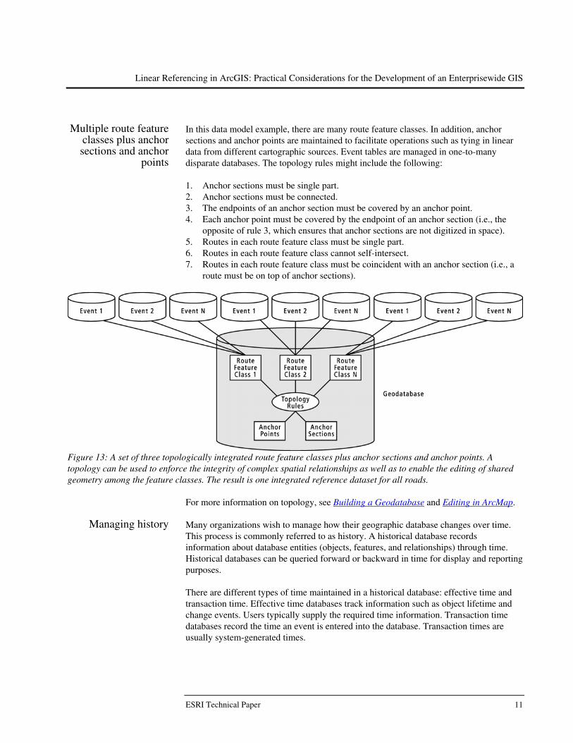
In this data model example, there are many route feature classes. In addition, anchor sections and anchor points are maintained to facilitate operations such as tying in linear data from different cartographic sources. Event tables are managed in one-to-many disparate databases. The topology rules might include the following:
1. Anchor sections must be single part. 2. Anchor sections must be connected. 3. The endpoints of an anchor section must be covered by an anchor point. 4. Each anchor point must be covered by the endpoint of an anchor section (i.e., the
opposite of rule 3, which ensures that anchor sections are not digitized in space). 5. Routes in each route feature class must be single part. 6. Routes in each route feature class cannot self-intersect. 7. Routes in each route feature class must be coincident with an anchor section (i.e., a
route must be on top of anchor sections).
Figure 13: A set of three topologically integrated route feature classes plus anchor sections and anchor points. A topology can be used to enforce the integrity of complex spatial relationships as well as to enable the editing of shared geometry among the feature classes. The result is one integrated reference dataset for all roads.
For more information on topology, see Building a Geodatabase and Editing in ArcMap.
Managing history Many organizations wish to manage how their geographic database changes over time. This process is commonly referred to as history. A historical database records information about database entities (objects, features, and relationships) through time. Historical databases can be queried forward or backward in time for display and reporting purposes. There are different types of time maintained in a historical database: effective time and transaction time. Effective time databases track information such as object lifetime and change events. Users typically supply the required time information. Transaction time databases record the time an event is entered into the database. Transaction times are usually system-generated times.
ESRI Technical Paper 11

Linear Referencing in ArcGIS: Practical Considerations for the Development of an Enterprisewide GIS
The effective time and the transaction time for an object in a database may be different. That is, there is generally a time lag between when an object is created or modified and when it is entered into the database. For example, organizations often have backlogs in entering data. Use of effective time in linear referencing applications is critically important. For example, imagine a scenario in which a road realignment was finished on January 10. Now imagine that a traffic accident occurred on January 21. Users need to locate the traffic accident against the state of the network on January 21. The ArcGIS system and geodatabase support these scenarios through historical versioning. Once historically enabled, typical queries made on historical databases include the following: Show me the database at time A—Depending on the temporal granularity of the
database, retrieving the exact time may not be possible. Show me how feature Y has changed through time—This is generally referred to as a
lineage search. Show me what is in the space of feature Z at time B—This is a similar query to the
lineage query but is used to determine what the current configuration of features is where the queried feature previously existed.
Refer to Modeling and Using History in ArcGIS or Managing Workflow with Versions for more information on the geodatabase’s versioning model.
Integrity constraints When data is stored in a geodatabase, rules can be defined about how the data can be edited. Geodatabase subtypes and domains ensure the attribute integrity of the database.
Subtypes allow you to define categories for objects and features. For example, there might only be five types of roads: interstate, expressway, minor arterial, collector, and local. Subtypes can be set up so that when a new road is entered, you can easily select the appropriate value from a list. Further, you can select the default value that is most likely to be associated with a road. For example, if 90 percent of your roads are local, you could set this to be your default value, thereby saving time. Finally, it is possible to set up topology rules between different subtypes within the same feature class. For example, you can specify that local roads and interstates cannot overlap one another. Domains control the allowable set of values that may be input for any field in a geodatabase table. This limits the possibility of data entry error because the choices for each data value are limited within defined parameters. There are two types of attribute domains: Coded Values—Specify listing of acceptable codes. For example, the possible
surface types for a stretch of road might be C (concrete), A (asphalt), or O (asphalt on concrete overlay).
Range—Specify acceptable starting and ending numeric values. For example, pavement quality scores might range from 1 to 10.
April 2003 12

Linear Referencing in ArcGIS: Practical Considerations for the Development of an Enterprisewide GIS
When viewed in ArcCatalog™ and ArcMap™, coded-value domains and subtypes are presented with their human-readable values. There is no need to memorize cryptic coding schemes. For more information on subtypes and domains, see Building a Geodatabase.
Developer support through application
programming interfaces
The geodatabase is accessed via the industry-standard menus, dialog boxes, and wizards of ArcGIS. Unlike some systems, however, all of the functionality exposed in the ArcGIS user interface is available via the ArcObjects™, OLE DB, and SQL APIs. These APIs provide an infrastructure for application customization that lets you concentrate on the specific needs of implementing your data model. The ArcObjects API alone contains more than 1,100 industry-standard Component Object Model-based components. For more information on any of the ArcGIS APIs, refer to Exploring ArcObjects.
Object behavior When a route is edited, events that are located along that route might become invalid. For example, an event that was located halfway along a route will no longer be located halfway along the route as the route’s shape becomes longer or shorter due to a realignment. As such, a mechanism is needed so that events can be notified when their underlying route has been altered in any way. Once notified, appropriate action can be taken.
Figure 14: Realigning a route causes its length to change. Events located on this route might need to be notified of such a change.
Notification mechanisms are available in the geodatabase and can be accessed via the ArcObjects API. For more information on the ArcObjects APIs, refer to Exploring ArcObjects.
Data interoperability Many linear referencing systems in place today are based on closed data models that are inaccessible to other applications. The geodatabase data model is a generic, multipurpose table model that is based on the standard table-based relational model and its spatial extensions (e.g., ISO SQL/MM Spatial, OGC Simple Features).
The multipurpose capability of the geodatabase enables tight integration of linear referencing and other traditional geospatial data stores. The ability to centrally integrate spatial data management across the organization offers significant benefits.
ESRI Technical Paper 13

Linear Referencing in ArcGIS: Practical Considerations for the Development of an Enterprisewide GIS
Figure 15: ArcGIS is able to access and use data collections from many departments or agencies in an integrated manner. The geodatabase data model also supports interactions from a variety of other applications.
Linear referencing The goal of a true enterprise GIS is not simply to provide a common place to store data.
A GIS also needs to provide front-end tools to assist its users in completing essential activities, such as creating, editing, displaying, querying, analyzing, and reporting the data. The following represent the fundamental requirements of a linear referencing application. All of these have been addressed in ArcGIS. For more information on any of the functionalities described below or for a more complete list of the linear referencing functionality available to you in ArcGIS, refer to Linear Referencing in ArcGIS.
Creating and editing route and event data
When implementing your linear referencing application, you will, of course, need route data. This data may not exist, may exist but without the appropriate measure system defined, or may exist in a format you do not wish to use. ArcGIS supports routes in three formats: coverage, shapefile, and geodatabase. ArcGIS comes with the tools necessary to create route data from a wide variety of input data sources, calibrate existing route data, and migrate route data from one supported format to another. Once created, a full suite of route editing tools is available to you. Functions such as split, merge, trim, copy, flip, reshape, move, and delete are available within the ArcMap editing environment. You simply select the routes you want to edit and apply the appropriate editing function.
April 2003 14

Linear Referencing in ArcGIS: Practical Considerations for the Development of an Enterprisewide GIS
In addition to tools for editing the geometry (shape) of a route feature, there are many tools available for editing a route’s measures. Examples include setting measures as the length of the feature, calibrating route measures with points, setting measures using known values, calculating unknown measure values, multiplying measures by a factor, and offsetting measures by a value. All of these measure editing functions can be applied to whole routes or to portions of routes.
Event display and query
When event data is stored in a database, it is only of so much use. The ability to display your event data on a map is essential. Once displayed, you can gain useful insight by just looking at it. Further, you can start to ask questions such as Where is...?, What is...?, Where is the closest...?, What’s inside...?, and What intersects...? To display route events on a map, however, you must first define the parameters of the relationship between the table storing the events and the routes that the events reference. Dynamic segmentation (DynSeg) is the process of computing the map location (shape) of events stored in an event table. Dynamic segmentation is what allows multiple sets of attributes to be associated with any portion of a linear feature.
Figure 16: Dynamic segmentation is the process of computing the map location of events stored in an event table.
ESRI Technical Paper 15

Linear Referencing in ArcGIS: Practical Considerations for the Development of an Enterprisewide GIS
Event tables often contain a large number of records with many attributes. You may, however, only want to display events on a small number of routes or events that meet a certain selection criteria. Further, you may only be interested in a subset of an event table’s attributes, or you may need to display the attributes from more than one table. The geodatabase data model allows for the creation of query-based tables. A query-based table is a virtual table that is created in memory using SQL-like statements. Query-based tables can be created from one or more input tables that reside in either a geodatabase or a workspace accessed through OLE DB. Query-based tables are created in the server before data is transported across the wire but do not create a new object in your database. Like any other table, a query-based table can be used for dynamic segmentation purposes. At ArcGIS 8.3, query-based tables are created via the ArcObjects API. For more information on query-based tables, refer to the samples on ESRI’s technical support page.
Transforming data between multiple linear referencing
methods
In organizations, event data is collected against multiple route reference systems. All of these methods represent valid ways to locate event data. For the event data to be truly useful, it must be possible to perform transformations among the different systems. Without this ability, each set of data that an organization has is independent and can only be analyzed and reported in relation to that set. Transformation enables integrating, reporting, and analyzing capabilities for data, thereby greatly improving the decision making process.
Figure 17: The ability to transform between different linear referencing methods is essential for well-informed decision making.
Event geoprocessing The naked eye is often not enough to truly understand the spatial relationships that exist
between features. It is often necessary to combine data in different ways to fully understand these relationships. The new data can then be used in ways not possible using traditional spatial analysis techniques. Overlaying events is one way to combine event data. This process combines two input event tables to create a single output event table that is either the intersection or the union of the input events. The union of the input events splits all linear events at their intersections and writes them to the new event table. The intersection of the input event tables writes only overlapping events to the output event table. Line-on-line, line-on-point (which is the same as point-on-line), and even point-on-point event overlays can be performed.
April 2003 16

Linear Referencing in ArcGIS: Practical Considerations for the Development of an Enterprisewide GIS
Figure 18: Comparing the union and intersect results for a line-on-line event overlay
Concatenating and dissolving event data are other ways to combine event data. Both operations combine event records in tables where there are events on the same route and they have the same value for specified fields. The result is written to a new event table. The difference between the two operations is that concatenating will only combine events in situations where the to-measure of one event matches the from-measure of the next event, while dissolving will combine events when there is measure overlap. The concatenate and dissolve processes are most often used to get rid of redundant event information, thereby making subsequent operations on the events more efficient. They are also used to reduce the number of fields in a table, thereby making pattern recognition in the data easier.
Figure 19: Comparing the concatenate and dissolve events results
Integrating nonlinear
referencing data Data comes from many sources in many forms. It is often desirable to incorporate this data into the linear referencing system for further analysis. For example, global positioning system point data is a common way to collect road infrastructure locations.
ESRI Technical Paper 17
Linear Referencing in ArcGIS: Practical Considerations for the Development of an Enterprisewide GIS
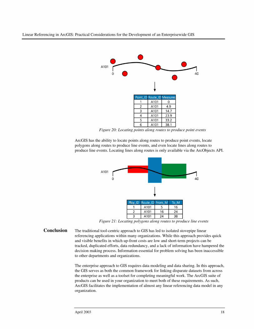
Figure 20: Locating points along routes to produce point events
ArcGIS has the ability to locate points along routes to produce point events, locate polygons along routes to produce line events, and even locate lines along routes to produce line events. Locating lines along routes is only available via the ArcObjects API.
Figure 21: Locating polygons along routes to produce line events
Conclusion The traditional tool-centric approach to GIS has led to isolated stovepipe linear
referencing applications within many organizations. While this approach provides quick and visible benefits in which up-front costs are low and short-term projects can be tracked, duplicated efforts, data redundancy, and a lack of information have hampered the decision making process. Information essential for problem solving has been inaccessible to other departments and organizations. The enterprise approach to GIS requires data modeling and data sharing. In this approach, the GIS serves as both the common framework for linking disparate datasets from across the enterprise as well as a toolset for completing meaningful work. The ArcGIS suite of products can be used in your organization to meet both of these requirements. As such, ArcGIS facilitates the implementation of almost any linear referencing data model in any organization.
April 2003 18