linear modelling (incl. fem) ae4asm003 p1 … · • why is this a constant strain triangle? 19....
TRANSCRIPT

LINEAR MODELLING (INCL. FEM) AE4ASM003 P1-2015
LECTURE 5 29.09.2015
1
TODAY…
• Isoparametric formulation • Constant strain triangular elements • Bending elements
2

ISOPARAMETRIC FORMULATION
3

FORMULATION PROPERTIES
• same interpolation functions for geometry and displacement • tedious/confusing! • simpler for computer program formulation • extended application to all element types • idealisation of elements with curved boundaries
4

NATURAL OR GENERALISED COORDINATE SYSTEM
ui uj
i j
l
X
i j
l
x1x2
r=-1 r=+1r
X
Y
Let us assume a polynomial for the geometry
Solving and substituting back into x,
Therefore,
where
5
(1)
(2)
(3)
(4)

6
This natural coordinate is attached to the bar no matter how it is oriented or placed in space
Therefore, a transformation to the global coordinate system must be made - Transformation mapping!i j
lr=-1 r=+1r=0
1
N1
i j
lr=-1 r=+1r=0
1
N2
r is the natural coordinate system
So, lets carry out the steps of the finite element analysis using this formulation:
Step 1: interpolation model
Step 2: strain and stress of the system
Step 3: stiffness matrix definition
Step 4: transformation
Step 5: load vector
Step 6: results

7
Step 2: strain and stress of the system
Strain in local coordinate
Strain in global coordinate
Substituting in (7),
(5)
(6)
(7)
where and (8)
(9)
8
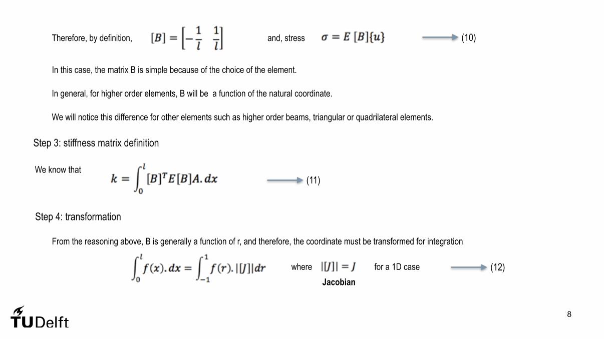
Therefore, by definition, and, stress
In this case, the matrix B is simple because of the choice of the element.
In general, for higher order elements, B will be a function of the natural coordinate.
We will notice this difference for other elements such as higher order beams, triangular or quadrilateral elements.
Step 3: stiffness matrix definition
We know that
Step 4: transformation
From the reasoning above, B is generally a function of r, and therefore, the coordinate must be transformed for integration
where
(10)
(11)
for a 1D case (12)Jacobian
9
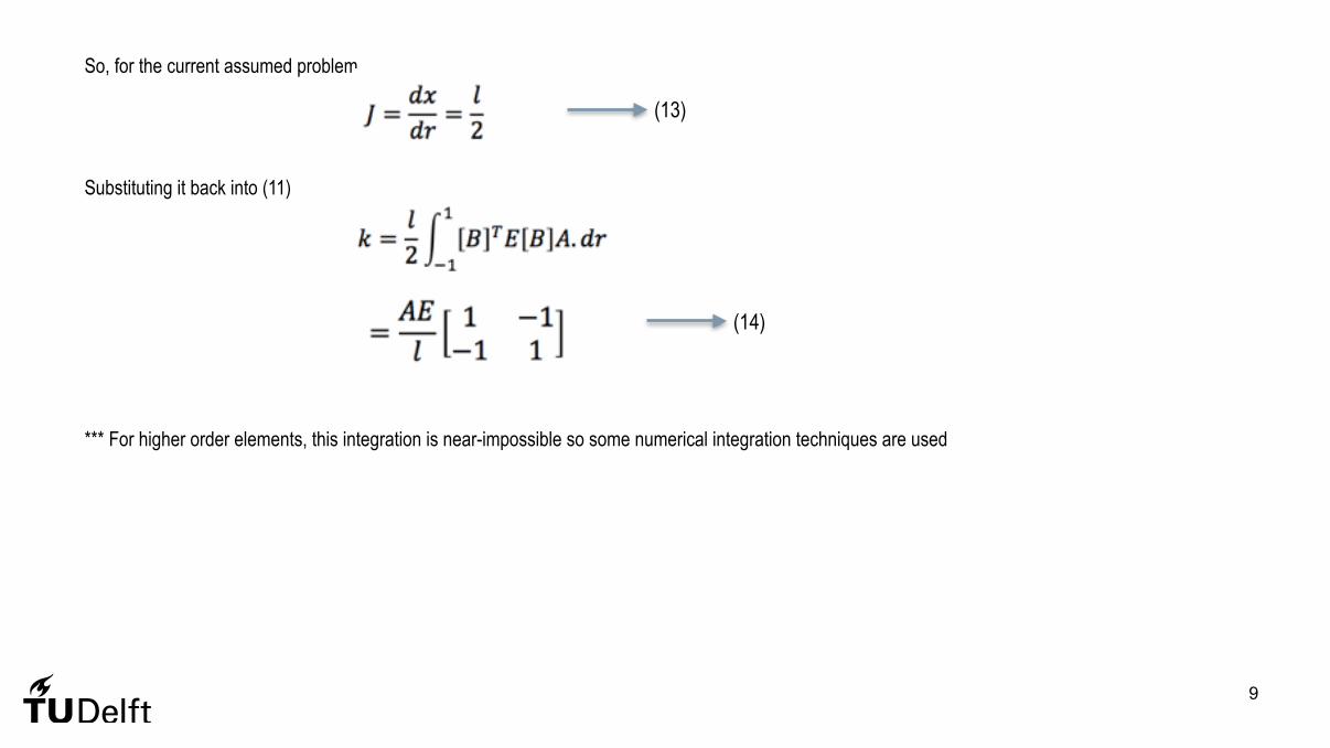
So, for the current assumed problem,
Substituting it back into (11)
*** For higher order elements, this integration is near-impossible so some numerical integration techniques are used
(13)
(14)

10
Step 5: load vector
Body forces
Surface forces
(15)
(16)

PLATE ANALYSIS
11

TYPES OF PLATE ELEMENTS
• Any plate under in-plane and transverse loads will deform in 3 spatial coordinates • Assuming the linear small deflection theory, uncoupling occurs
• in-plane (membrane) forces • transverse (bending) forces
12

MEMBRANE ELEMENTS - CONSTANT STRAIN TRIANGLES
13
14
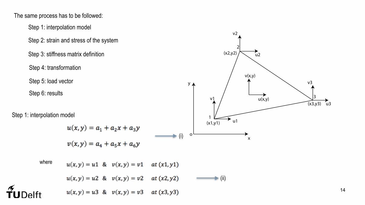
Step 1: interpolation model
Step 2: strain and stress of the system
Step 3: stiffness matrix definition
Step 4: transformation
Step 5: load vector
Step 6: results
The same process has to be followed:
x
y
o
(x1,y1)
(x2,y2)
(x3,y3)
1
2
3u(x,y)
v(x,y)
u1
v1
u2
v2
u3
v3
Step 1: interpolation model
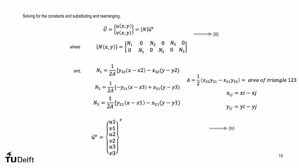
where
(i)
(ii)
15
Solving for the constants and substituting and rearranging,
where
and,
(iii)
(iv)
16
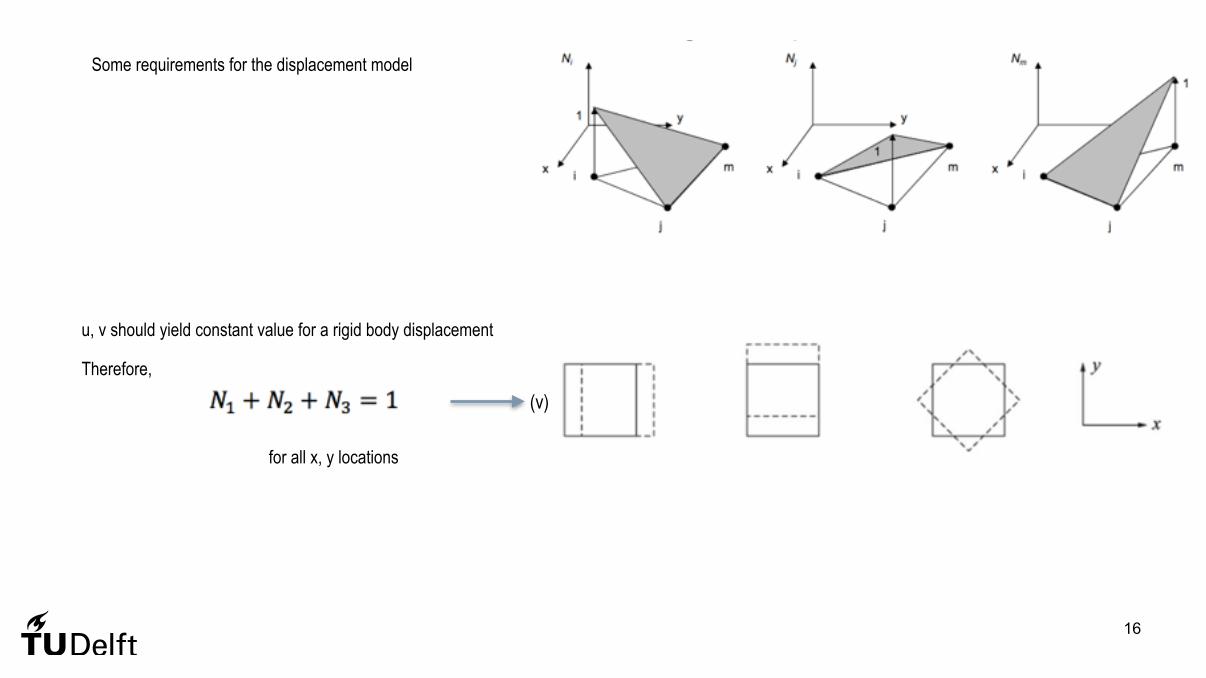
Some requirements for the displacement model
u, v should yield constant value for a rigid body displacement
Therefore,
for all x, y locations
(v)

17
From solid mechanics,
which can be written in terms of nodal displacements as,
where
For a plane stress condition,
where and,
(vi)
(vii)
(viii)

18
Stiffness matrix
Since in this case, the matrices B and D are constants and are independent of spatial coordinates, the thickness can be extracted to give,
Transformation?
In-plane
where and,
Stiffness matrix, load vector, displacements!
(ix)
(x)
CHARACTERISTICS
• displacement model should be continuous • why is this a constant strain triangle?
19

PLATE BENDING
20

PLATE BENDING BEHAVIOUR
• thickness is small as compared to other dimensions • deflections are small • mid-plane does not undergo in-plane deformation • transverse shear deformation is zero
21

FINITE ELEMENT ANALYSIS OF PLATE BENDING
• special elements - transverse deflection of middle surface only • other elements - include transverse shear
• displacement model • ‘w’ should be continuous • derivative should be continuous • for convergence, assumed displacement model will have constant curvature states
22
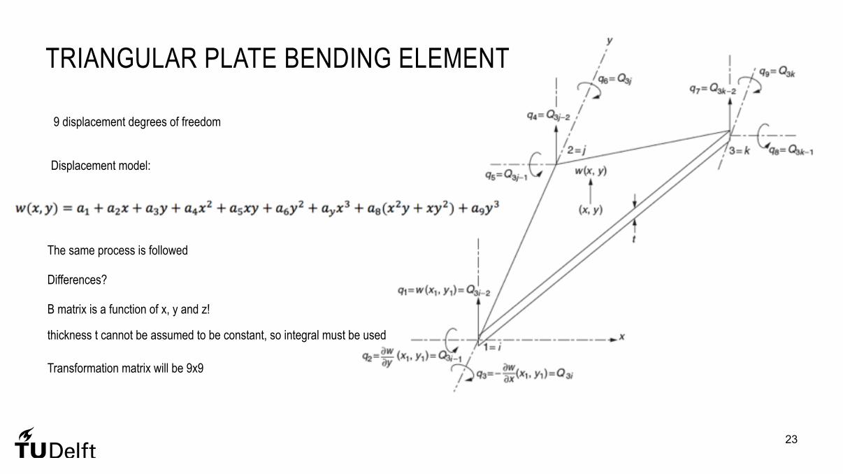
TRIANGULAR PLATE BENDING ELEMENT
23
9 displacement degrees of freedom
Displacement model:
The same process is followed
Differences?
B matrix is a function of x, y and z!
thickness t cannot be assumed to be constant, so integral must be used
Transformation matrix will be 9x9

HOMEWORK
• Check blackboard for practice problems on membrane and bending plates • Answer Self-Check questions and discuss on the forum • Continue working on Homework assignment 2.
24

NEXT WEEK…
• Post processing • Convergence • Strain energy error
25