linear encapsulated power modules devices, inc. specifications features • ul, ce & csa...
TRANSCRIPT

POLYTRON DEVICES, Inc.
Specifications
FEATURES
• UL, CE & CSAApproved (All Models)
• Regulation Line &Load 0.2% to 0.02%
• P.C. Card/ChassisMounting
• High Isolation VoltageAvailable
• Short CircuitProtection
• Single, Dual & TripleOutputs
• Finger Safe TerminalAvailable
P3, P5 Series
115 Vac, 50 to 400 Hz @ 25°C
INPUTVoltage Range................................................105-125 Vac, 50-60 Hz
...........................................................400Hz available
OUTPUTVoltage Accuracy @ FL for Singles, ................................ .......±1.0%Line Regulation: Single Output.....................................±0.2%Load Regulation: Single Output.....................................±0.2%Temperature Coefficient .............................................±0.02%/°C typ.
GENERALIsolation Resistance...........................................................50MOhmsProtection.......................................................Short Circuit Protection
ENVIRONMENTALOperating Temperature Range........................................-25 to +71°C
........................-40 to +85°C OptionalStorage Temperature Range...........................................-25 to +85°CCooling................................................................Free Air Convection
PHYSICALDimensions..................................................See Chart and Diagrams
P.O. Box 398, Paterson, New Jersey 07544 U.S.A.Tel: (973)345-5885 Fax: (973)345-1264 • Email: [email protected] • www.polytrondevices.com
P
83
1. Case style ending with letter “T”(Chassis mounted units with terminal barrier strip) are designatedby the suffix “T” . Case styles A,B,C,D,G and E (PC card mounting) do not require suffixing.
2. Most competitors pinouts available--contact factory.3. For 400HZ, use suffix “04” after model number.4. For wide operating temperature range, use “W” suffix after model number.
FAST DELIVERY
LINEAR ENCAPSULATEDPOWER MODULESREGULATED 5Vdc-250VdcP.C. CARD OR CHASSIS MOUNTING

Selection Guide
Linear Encapsulated Power Modules
(Continued)
POLYTRON DEVICES, Inc.P.O. Box 398, Paterson, New Jersey 07544 U.S.A.
Tel: (973)345-5885 Fax: (973)345-1264 • Email: [email protected] • www.polytrondevices.comP
Output Output Current Ripple & Case Model Number Slow Blow (Vdc) (mA) Line Load (mV rms) (A)
200 0.20% 0.20% 1.0 G, 1GT P34-5SM 1/32 500 0.20% 0.20% 0.5 A, 1AT P37 1/16 500 0.02% 0.05% 0.5 A, 1AT P37-1 1/16
1000 0.20% 0.20% 1.0 B, 1BT P38 1/8 1000 0.02% 0.05% 1.0 B, 1BT P38-1 1/8 1000 0.02% 0.05% 0.5 C, 1CT P38/1.56 1/8 2000 0.02% 0.10% 1.0 C, 1CT P39 1/4 3000 0.02% 0.15% 1.0 D, 1DT P39-3 3/8 120 0.10% 0.10% 1.0 E, 1ET P33-10SM 1/32 150 0.10% 0.10% 1.0 A, 1AT P33-10S 1/16 250 0.10% 0.10% 1.0 B, 1BT P34-10S 1/16 500 0.02% 0.05% 0.5 C, 1CT P37-10S 1/8
1000 0.02% 0.05% 0.5 D, 1DT P38-10S 3/8 1500 0.02% 0.05% 0.5 D, 1DT P38-10SA 1/4 100 0.10% 0.10% 1.0 E, 1ET P32-12SM 1/32 120 0.02% 0.10% 1.0 A, 1AT P33-12S 1/16 200 0.10% 0.10% 1.0 B, 1BT P34-12S 1/16 500 0.02% 0.10% 0.5 C, 1CT P37-12S 1/5
1000 0.10% 0.10% 1.0 D, 1DT P38-12S 3/10 80 0.10% 0.10% 1.0 E, 1ET P33-15SM 1/32
120 0.02% 0.10% 1.0 A, 1AT P33-12S 1/16 200 0.10% 0.10% 1.0 B, 1BT P34-15S 1/10 300 0.10% 0.10% 1.0 C, 1CT P35-15S 1/8 500 0.02% 0.10% 0.5 C, 1CT P37-15S 1/5 800 0.02% 0.10% 1.0 D, 1DT P38-15S 3/10 50 0.10% 0.10% 1.0 E, 1ET P32-18SM 1/32 50 0.02% 0.05% 1.0 A, 1AT P32-18S 1/32
100 0.02% 0.05% 1.0 B, 1BT P33-18S 1/16 50 0.10% 0.10% 1.0 E, 1ET P32-24SM 1/32
100 0.10% 0.10% 1.0 A, 1AT P33-24S 1/16 200 0.10% 0.10% 1.0 B, 1BT P34-24S 1/8 300 0.10% 0.10% 1.0 C, 1CT P35-24S 1/5 500 0.10% 0.10% 1.0 D, 1DT P37-24S 1/4 800 0.10% 0.10% 1.0 H, 1HT P38-24S 3/8
1000 0.10% 0.10% 1.0 H, 1HT P39-24S 1/2 50 0.20% 0.20% 2.0 B, 1BT P32-48S 1/16
100 0.20% 0.20% 2.0 B, 1BT P33-48S 1/8 200 0.20% 0.20% 2.0 C, 1CT P34-48S 1/4 50 0.05% 0.20% 2.0 B, 1BT P32-50S 1/16
100 0.05% 0.20% 2.0 B, 1BT P33-50S 1/8 200 0.05% 0.20% 2.0 C, 1CT P34-50S 1/4 300 0.20% 0.20% 3.0 D, 1DT P35-50S 3/8 35 0.05% 0.20% 2.0 B, 1BT P32-75S 1/10 70 0.05% 0.20% 2.0 B, 1BT P33-75S 1/5
150 0.05% 0.20% 2.0 C, 1CT P34-75S 3/10 200 0.10% 0.20% 3.0 D, 1DT P35-75S 3/8 25 0.05% 0.20% 2.0 B, 1BT P32-100S 1/16 50 0.05% 0.20% 2.0 B, 1BT P33-100S 1/8
100 0.05% 0.20% 3.0 C, 1CT P34-100S 1/4 150 0.10% 0.20% 3.0 D, 3DT P35-100S 3/8
SIN
GL
E O
UT
PU
T V
OL
TA
GE
15
75
100
18
24
48
50
Regulation
5
10
12
Linear Encapsulated Power Modules 5Vdc-250Vdc output
1. Case style ending with letter “T”(Chassis mounted units with terminal barrier strip) are designated by the suffix “T” . Case styles A,B,C,D,G and E (PC card mounting) donot require suffixing.
2. Most competitors pinouts available--contact factory.3. For 400HZ, use suffix “04” after model number.4. For wide operating temperature range, use “W” suffix after model number.
84
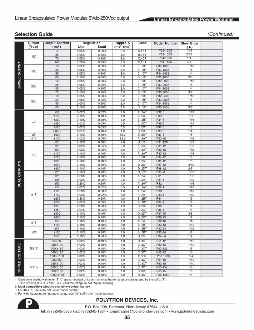
Selection Guide
Linear Encapsulated Power Modules 5Vdc-250Vdc output Linear Encapsulated Power Modules
(Continued)
POLYTRON DEVICES, Inc.P.O. Box 398, Paterson, New Jersey 07544 U.S.A.
Tel: (973)345-5885 Fax: (973)345-1264 • Email: [email protected] • www.polytrondevices.comP
Output Output Current Rippl e & Case Model Number Slow Blow (Vdc) (mA) Line Load (mV rms) (A)
17 0.05% 0.20% 2.0 A,1AT P32-150S 1/16 35 0.05% 0.20% 3.0 B,1BT P33-150S 2/10 70 0.05% 0.20% 3.0 C,1CT P34-150S 1/4
100 0.20% 0.20% 3.0 D,1DT P35-150S 3/8 15 0.05% 0.20% 3.0 B, 1BT P32-180S 1/16 30 0.05% 0.20% 3.0 B, 1BT P33-180S 1/5 55 0.05% 0.20% 3.0 C, 1CT P34-180S 1/4 80 0.10% 0.20% 3.0 D, 1DT P35-180S 3/8 12 0.05% 0.20% 3.0 B, 1BT P32-200S 1/16 25 0.05% 0.20% 3.0 B, 1BT P33-200S 1/8 50 0.05% 0.20% 3.0 C, 1CT P34-200S 1/4 75 0.10% 0.20% 3.0 D, 1DT P35-200S 3/8 10 0.05% 0.20% 3.0 B, 1BT P32-250S 1/16 20 0.05% 0.20% 3.0 B, 1BT P33-250S 1/8 40 0.05% 0.20% 3.0 C, 1CT P34-250S 1/4 60 0.10% 0.20% 3.0 D, 1DT P35-250S 3/8
±50 0.02% 0.02% 1.0 A, 2AT P32-5 1/32 ±100 0.10% 0.10% 1.0 A, 2AT P33-5 1/32 ±200 0.10% 0.10% 1.0 B, 2BT P34-5 1/16 ±300 0.02% 0.05% 0.5 C, 2CT P35-5 1/10 ±500 0.02% 0.05% 0.5 C, 2CT P37-5 1/8
±1000 0.01% 0.10% 1.0 D, 2DT P38-5 1/4 ±8 ±500 0.10% 0.10% 82.0 D, 2DT P37-8 1/5 ±10 ±100 0.02% 0.05% 82.0 A, 2AT P33-10 1/16
±25 0.10% 0.10% 2.0 G, 1GT P31-12M 1/32 ±25 0.02% 0.05% 5.0 A, 2AT P31-12 1/32 ±50 0.02% 0.05% 5.0 A, 2AT P32-12 1/32
±100 0.10% 0.10% 1.0 A, 2AT P33-12 1/16 ±200 0.10% 0.10% 1.0 B, 2BT P34-12 1/8 ±300 0.10% 0.10% 1.0 C, 2CT P35-12 1/5 ±500 0.10% 0.10% 1.0 D, 2DT P37-12 3/10 ±800 0.10% 0.10% 1.0 D, 2DT P38-12 2/5 ±25 0.10% 0.10% 2.0 G, 1GT P31-M 1/32 ±25 0.20% 0.20% 1.0 A, 2AT P31 1/32 ±25 0.02% 0.02% 0.5 A, 2AT P31-1 1/32 ±50 0.20% 0.20% 1.0 A, 2AT P32 1/16 ±50 0.02% 0.02% 0.5 A, 2AT P32-1 1/16
±100 0.20% 0.20% 1.0 A, 2AT P33 1/10 ±100 0.02% 0.02% 1.0 A, 2AT P33-1 1/10 ±200 0.20% 0.20% 1.0 B, 2BT P34 1/5 ±200 0.02% 0.05% 1.0 B, 2BT P34-1 1/5 ±350 0.20% 0.20% 1.0 C, 2CT P35 1/4 ±350 0.02% 0.05% 1.0 C, 2CT P35-1 1/4 ±500 0.10% 0.10% 1.0 D, 2DT P37-15 3/8 ±800 0.10% 0.10% 1.0 D, 2DT P38-15 1/2 ±50 0.10% 0.10% 1.0 A, 2AT P32-18 1/16
±100 0.10% 0.10% 1.0 B, 2BT P33-18 1/10 ±50 0.10% 0.10% 1.0 B, 2BT P32-24 1/16
±100 0.10% 0.20% 1.0 B, 2BT P33-24 1/8 ±200 0.10% 0.20% 1.0 C, 2CT P34-24 1/4
250/±60 0.02% 0.10% 1.0 C, 3CT P51-12 1/10 250/±120 0.02% 0.10% 1.0 C, 3CT P52-12 1/10 300/±180 0.02% 0.10% 1.0 C, 3CT P53-12L 1/5 500/±120 0.02% 0.10% 1.0 C, 3CT P53-12 1/5
1000/±150 0.02% 0.10% 1.0 D,3DT P53-1280 1/4 250/±50 0.02% 0.10% 1.0 C, 3CT P51-15 1/10
250/±100 0.02% 0.10% 1.0 C, 3CT P52-15 1/10 300/±150 0.02% 0.10% 1.0 C, 3CT P53-15L 1/5 500/±100 0.02% 0.10% 1.0 C, 3CT P53-15 1/5
1000/±150 0.02% 0.10% 1.0 D, 3DT P53-1580 1/4
±18
±5
±12
±15
SIN
GL
E O
UT
PU
TT
RIP
LE
VO
LT
AG
ED
UA
L O
UT
PU
TS
±24
5/±12
5/±15
Regulation
180
200
250
150
1. Case style ending with letter “T”(Chassis mounted units with terminal barrier strip) are designated by the suffix “T” . Case styles A,B,C,D,G and E (PC card mounting) do not require suffixing.
2. Most competitors pinouts available--contact factory.3. For 400HZ, use suffix “04” after model number.4. For wide operating temperature range, use “W” suffix after model number.
85

P3, P5 SERIES
POLYTRON DEVICES, Inc.P.O. Box 398, Paterson, New Jersey 07544 U.S.A.
Tel: (973)345-5885 Fax: (973)345-1264 • Email: [email protected] • www.polytrondevices.comP
Mechanical Specification
OPTIONS AVAILABLE SUFFIX Pin SINGLE DUAL TRIPLE 220Vac X 1 -Vdc* -Vdc* Com (5) 230Vac XA 2 No Pin No Pin +5Vdc 240Vac XE 3 Com* Com* -12 / -15 100Vac Q 4 No Pin No Pin CMN (12/15) 115/220 AX 5 +Vdc +Vdc +12 / +15 Alternate Pin-Out 22
single output units.
Finger Safe Chassis MountTerminal Barrier Strip
Wide Oper. Temp. Range W 400Hz
I/O Connections
FST
TChassis mounting with terminal barrierstrip (case styles ending with letter ("T")
* -Vdc Internally connected to COM for
Linear Encapsulated Power Modules 5Vdc-250Vdc output
2 Most competitors pinouts available--contact factory.
86
BOTTOMVIEW
0.875 (22.2)
0.175(44.5)
0.15 (38.1)1.70
(43.2)
0.15 (38.1)
0.85 (21.6)
0.85 (21.6)
1.65(41.9)
2.00(51.0)
2.00(51.0)
0.20 (5.1)LG MIN
0.40 (1.0) DIA PIN
CASE G
1
2
3AC
AC
G
P34-5SM: 1 + 5VDC 2 and 3 COMP31-M + P31-12M: 1 - 15VDC 2 COM 3 + 15VDC
2 2
2
04
SIDE VIEWBOTTOM VIEW
All Dimensions are in inches (mm)
1.75 (44.5)
0.20 (5.10)
2.25(57.15)
1.80(45.70)
1.00 (25.4)0.20(5.10)MIN
0.275(7.1)
0.40 (1.0) DIA PINS
1.20(30.5)
0.60(15.2)
CASE E
MOUNTING#4-40 x 0.12(3.0 DEEP)
AC
+
AC
E
BOTTOM VIEW
2.0 (51.0)
2.5 (63.5)
0.1(2.54)
3.2 (81.3)
2.0(51.0)
0.15 ((3.81) REF0.15 REF
3.5 (88.9)
0.75 (19.1)
0.75 (19.1)
1.0(25.4)
0.15 (3.81)REF0.25 REF(6.35)
20 MIN .040 (10.16)DIA PINS
1.1(27.9)
0.55(13.97)
2.2(55.9)
1.56(39.6)1.25
(31.8)0.875(22.2)
CASE A, B, C, D
CL
TWOMOUNTING
INSERTS#4-40 x 0.1 DEEP
AC 1
2
3
4
5AC
A
B
C
D
-TRIM

Linear Encapsulated Power Modules
(Continued)
POLYTRON DEVICES, Inc.P.O. Box 398, Paterson, New Jersey 07544 U.S.A.
Tel: (973)345-5885 Fax: (973)345-1264 • Email: [email protected] • www.polytrondevices.comP
All Dimensions are in inches (mm)
CHASSIS MOUNTED UNITS
TOP VIEW
SINGLE OUTPUT MODELS
DUAL OUTPUT MODELS
TRIPLE OUTPUT MODELS
FOUR MOUNTINGINSERTS
#4-40 x 0.1 DEEP1AT
AC
AC
CMN
V+1BT
1CT
1DT
1.25(31.75)
2.50(63.5)
1.35(34.29)1.56
(39.11)
2.00(50.8)
TOP VIEW
AC
AC
V-
CMN
2.50(63.5)
1.68(42.67)
V+
TOP VIEW
AC
AC
V-
CMN2.50
(63.5)2.32
(58.93)
V+
5V CMN
+5
4.10(104.1)
BOTTOM VIEW2.00
(50.8)
2.50(63.5)
FOUR MOUNTINGINSERTS
#4-40 x 0.1 DEEP
BOTTOM VIEW
2.00(50.8)
2.50(63.5)
FOUR MOUNTINGINSERTS
#4-40 x 0.1 DEEP
BOTTOM VIEW
2.00(50.8)
2.50(63.05)
0.875(19.05)
2AT
2BT
2CT
2DT
3BT
3CT
3DT
1.25(31.75)
1.56(39.11)
2.00(50.8)
1.25(31.75)
1.56(39.11)
2.00(50.8)
0.875(19.05)
4.10(104.1)
4.10(104.1)
All Dimensions are in inches (mm)
SIDE VIEW
BOTTOMVIEW
1.62(41.1)
1.25(31.8)
0.88(22.4)
0.04 (1.0)DIA. PINS
0.20 (5.10) MIN
2.00(50.8)
2.50(63.5)
0.15(3.80)
0.50(12.7)
0.50(12.7)
0.60(15.2)
0.60(15.2)
1.60(40.6)
1.60(40.6)
2.20(55.9)
1.0(25.4)
3.50(88.9)
INSERTS4.40 THREAD
0.12 (3.2) DEEP
A
AC
COM5V
COM +5V +-
ACBOTTOM
VIEW
2.50(63.5)
0.15(3.80)
1.10(27.9)
1.10(27.9)
1.60(40.6)
1.60(40.6)
2.20(55.9)
3.50(88.9)
INSERTS4.40 THREAD
0.12 (3.2) DEEP
AC
COM +OUT-OUT
AC
B C D
ALTERNATE PIN-OUTTRIPLE OUTPUT MODELS
Note:* No connection for single output units* To specify alternate pin-out use suffix "22"
SINGLE & DUAL OUTPUT MODELS
Linear Encapsulated Power Modules 5Vdc-250Vdc output
Power Supply Options
87
1.0(25.4)

P 3, P 5 S E R IE S
(C ontinued)
P OLYT R ON DE V IC E S , Inc .P.O. B ox 398, Paterson, New J ersey 07544 U.S .A.
Tel: (973)345-5885 Fax: (973)345-1264 • Email: [email protected] • www.polytrondevices.com.P
4.20(106.68)
4.20(106.68)
3.20(81.28)
3.20(81.28)
1.10(27.94)
2.64(67.06)
0.25 (6.35)
0.16 (4.064)
3/32
2.00 NOTE 1(50.8)
AA
B . T eflon ins er ts
B
PO WER S UPPL Y S OC KETS
1.10
3/32AA
B . T eflon ins er ts
B
4.20(106.68)
3.20(81.28)
2.00(50.8)
3.20(81.28)
4.20(106.68)
2.64(67.06)
0.16 (4.064)
0.25 (6.35)
B E NC H A DA P T E R
S OC K E T S
Des igned for a ll S ingle a nd Dua l L inea rP ower S upplies in C a s es A , B , C , D.
MODE L M-5 (2.0" A C P in S pa c ing)M-5/22(2.2" A C P IN S P A C ING )
A ll Dimens ions a r e in inc hes (mm)
88
NOT E 1: F or 2.2" A C pin s pa c ing s pec ify S -5/22
A . 0.141 hole for mounting unit A . 0.141 hole for mounting unit
POWER SUPPLY ACCESSORIES
BBA A
AB B
A
B B
AB B A
BAA
B
B B