linear and circular microphone array for remote ... · abdulla alshehhi, m. luai hammadih, m. sami...
TRANSCRIPT

Linear and Circular Microphone Array for RemoteSurveillance: Simulated Performance Analysis
Abdulla AlShehhi, M. Luai Hammadih, M. Sami Zitouni, Saif AlKindi, Nazar Ali, and Luis WeruagaDepartment of Electrical and Computer Engineering
Khalifa University of Science, Technology and ResearchSharjah, United Arab Emirates
Abstract—Acoustic beamforming with a microphone arrayrepresents an adequate technology for remote acoustic surveil-lance, as the system has no mechanical parts and it has moderatesize. However, in order to accomplish real implementation, severalchallenges need to be addressed, such as array geometry, micro-phone characteristics, and the digital beamforming algorithms.This paper presents a simulated analysis on the effect of thearray geometry in the beamforming response. Two geometriesare considered, namely, the linear and the circular geometry.The analysis is performed with computer simulations to mimicreality. The future steps comprise the construction of the physicalmicrophone array, and the software implementation on a multi-channel digital signal processing (DSP) system.
I. INTRODUCTION
Array beamforming [1] is a promising technique for audiosurveillance and multi-conferencing. This technique enablesthe capture of a desired sound arriving from a certain spatial di-rection while suppressing undesired sounds coming from otherdirections . Applications such as acoustic surveillance, i.e. theunobtrusive monitoring and acoustic tracking of people locatedat relatively far distances and in actual noisy environments, canbenefit from sound beamforming systems as these microphonearrays do not have mechanical movable parts. Certain compactarray geometries make it possible for such microphone arraysystems to be implemented and used effectively in acousticsurveillance and multi-conferencing.
Acoustic beamforming has been thoroughly studied [3],[4].A microphone array is composed of several microphonesaligned in a specific pattern or geometry to operate as a singledevice. Microphone arrays appeared nearly three decades ago,but this is still a field with active research [2], [5–10]. A micro-phone array has the capability of separating between varioussignals by utilizing some techniques of filtering, substantiallyboosting the signal to noise ratio (SNR). The reading of allmicrophones are sampled and processed on a digital signalprocessing (DSP) computer to obtain the relevant signal anddiscarded the unwanted one. It can be utilized for variousapplications, for instance, finding the location of sound sourcesor distinguish between sounds according to direction withoutthe need to physically move the array of microphones.
The aim of this paper is to explore and understand thetwo main microphone array geometries, namely linear andcircular, implement then in a software simulation environment,and carry out a quantitative and qualitative comparative perfor-
mance analysis. The paper is structured as follows: Firstly, anillustration of the principles of beamforming is presented basedon two structures, linear array beamformer and circular arraybeamformer in order to compare between them. After that,results of simulation done based on linear array and circulararray beam-pattern are provided to verify which configurationgives the best performance. Finally the further work andconclusions close the paper.
II. PRINCIPLES OF BEAMFORMING
A. Linear Array Beamformer
Figure 1 illustrates schematically the basic delay-and-sum(DaS) beamformer on a linear array. The sound source given bys(t) arrives at the direction given by θ, while the microphonearray has been set up to point to the direction φ. In far-fieldconditions (the distance of the sound source is much largerthan the array size), the signal captured by by kth microphoneresults in
xk(t) = s(t−∆k) (1)
where ∆k represents the physical time delay at the kthmicrophone. It is simple to deduce that for such a geometricarrangement, the delay ∆k corresponds to
∆k = (d/c)(k − (N + 1)/2
)cos θ (2)
Fig. 1. Uniform linear 8-microphone array. Angle φ corresponds to thesteering angle and θ to the direction of sound arrival.
arX
iv:1
703.
0231
8v1
[cs
.SD
] 7
Mar
201
7

where d is the distance between adjacent microphones, c isthe speed of sound in air, N is the number of microphones,and the microphone index k runs as k = 1, · · · , N . Note thatthe signal at the microphone is then sampled and sent to adigital signal processor. However, for the sake of simplicity inthe exposition, we will use continuous time in the subsequentanalysis. The kth channel is then digitally delayed as
zk(t) = xk(t+ δk) (3)
where δk corresponds to the digital delay applied to the kthchannel. Since the array is meant to be pointing to angle φ,the digital delay δk can be easily obtained from (2), that is,
δk = (d/c)(k − (N + 1)/2
)cosφ. (4)
Finally, all channels are averaged, this resulting in the finalDaS signal as follows
y(t) =1
N
N∑k=1
zk(t) =1
N
N∑k=1
s(t−∆k + δk). (5)
If the steering angle φ is set to the actual direction of theincoming sound θ, the physical and digital delays compensate(δk = ∆k), and the beamformer output is equal to the soundsource signal, y(t) = s(t). In general, the averaging amongthe signals at the adder results in the frequency-selectiveattenuation of the signal, as the translation of the beamformeroutput (5) to the frequency domain reveals
Y (ω) = Hφ(ω, θ)S(ω). (6)
Here ω is frequency, Y (ω) and S(ω) correspond to the Fouriertransform of y(t) and s(t) respectively, and Hφ(ω, θ) is thetransfer function of the beamformer with steering angle φ
Hφ(ω, θ) =1
N
N∑k=1
exp(−jω(∆k − δk)
). (7)
It is immediate to see that if the incoming sound arrives atthe steering angle θ = φ, then ∆k = δk, hence Hφ(ω, θ) = 1,that is, the sound signal is captured without spectral distor-tion. The linear geometry presents unfortunately an additionalsituation at which ∆k = δk, which is for θ = −φ. This“ambiguity” lobe is as dominant as the main one. In any othercase θ 6= φ, the beamformer output will undergo a certainfrequency-selective attenuation according to (7).
B. Circular Array Beamformer
Figure 2 depicts the same DaS principle in a microphonearray with circular geometry. This figure illustrates also thedelay pattern at all the microphones: the delay pattern followsa trigonometric relation determined by the angle of eachmicrophone k2π/N with respect to the direction of arrivalθ. The physical delay that the incoming sound experiencesat each microphone depends on the difference between theprevious angles, that is,
∆k = (r/c) cos(θ − k2π/N
)(8)
Fig. 2. Uniform circular 8-microphone array.
where r is the radius of the circular geometry. It is importantto relate the radius r with the distance between adjacentmicrophones d, a relation that follows
d = 2r sin(π/N) (9)
The digital delays follow the same trigonometric rule (8)depending on the steering angle φ
δk = (r/c) cos(φ− k2π/N
). (10)
Unlike in the linear case, the circular geometry does notpresent any “ambiguity” lobe: the equation δk = ∆k, that is,
cos(φ− k2π/N
)= cos
(θ − k2π/N
)(11)
has only one solution, namely, θ = φ.
III. SIMULATION RESULTS
This part sheds light on the differences between a uniformlinear and circular 8-microphone array by means of the re-spective simulated beam pattern and beam patterns in polarcoordinates at three different single frequencies.
A. Linear and Circular Array Beam Pattern
The beamformer response of a microphone array is anexpedient characteristic that can be utilized to evaluate theanticipated performance of the beamformer, and it can beexploited as a gauge to indicate the capability of a beam-former to pass acoustic signals from a preferred direction andreject acoustic signals from other directions. The beamformerresponse Hφ(ω, θ) of a microphone array is also called beampattern. We establish here a comparison between the responseof a uniform linear and circular 8-microphone array. The beam

Fig. 3. Beam pattern of a linear 8-microphone array
Fig. 4. Beam pattern of a circular 8-microphone array.
pattern is frequency ω and DoA θ dependent, a two-dimensionsThe frequency response of the DaS beamformer is calcu-
lated over a significant frequency range of interest, namely,from 300 Hz to 4000 Hz, hence the following figures areobtained for linear and circular arrays. Figure 3 portrays thebeam pattern for 8-microphone linear array, whereas Figure
Fig. 5. Polar plot of the beam pattern for a linear (left) and circular (right)8-microphone array with d = 6 cm and for frequencies (from top to bottom):300 Hz, 2000 Hz, and 4000 Hz.
4 describes the beam pattern for 8-microphone circular array.For both geometries, the distance between the microphonesin the array is small (d = 6 cm). The simulation over 360◦
in the linear array, generates two main lobes located at 90◦
and 270◦. While the simulation in the circular array, producesone main lobe located at 90◦ and seven other lobes withnegligible magnitude. Therefore, the total number of lobesin the response of the circular array is eight. In both linearand circular arrays, for a fixed beam pattern length, the beamwidth is decreasing much more with increasing frequency.As shown in linear array, the response at the direction ofthe two main lobes is unity gain in linear scale. Therefore,the beamforming is enormously enhanced for medium andhigh frequencies. Furthermore, there is no aliasing in thesampled acoustic signal. The beam pattern of the circular arraydemonstrates that the main lobe has a unity gain in linear scaleat 90◦ steering angle. However, the beamforming is poor atlow frequencies. Other lobes such as the one at 270◦ haveincomparable response and they reject the acoustic signals
t
kHz
kHz
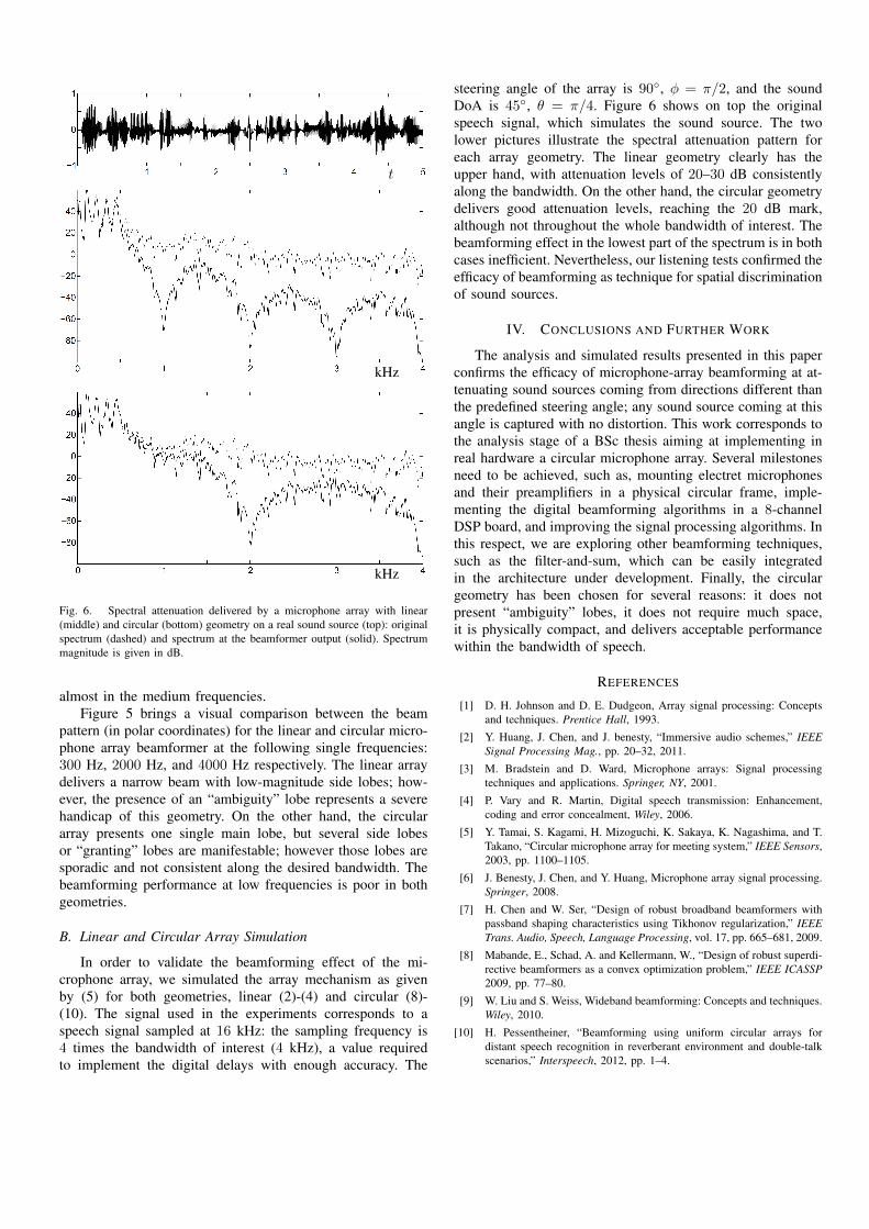
Fig. 6. Spectral attenuation delivered by a microphone array with linear(middle) and circular (bottom) geometry on a real sound source (top): originalspectrum (dashed) and spectrum at the beamformer output (solid). Spectrummagnitude is given in dB.
almost in the medium frequencies.Figure 5 brings a visual comparison between the beam
pattern (in polar coordinates) for the linear and circular micro-phone array beamformer at the following single frequencies:300 Hz, 2000 Hz, and 4000 Hz respectively. The linear arraydelivers a narrow beam with low-magnitude side lobes; how-ever, the presence of an “ambiguity” lobe represents a severehandicap of this geometry. On the other hand, the circulararray presents one single main lobe, but several side lobesor “granting” lobes are manifestable; however those lobes aresporadic and not consistent along the desired bandwidth. Thebeamforming performance at low frequencies is poor in bothgeometries.
B. Linear and Circular Array Simulation
In order to validate the beamforming effect of the mi-crophone array, we simulated the array mechanism as givenby (5) for both geometries, linear (2)-(4) and circular (8)-(10). The signal used in the experiments corresponds to aspeech signal sampled at 16 kHz: the sampling frequency is4 times the bandwidth of interest (4 kHz), a value requiredto implement the digital delays with enough accuracy. The
steering angle of the array is 90◦, φ = π/2, and the soundDoA is 45◦, θ = π/4. Figure 6 shows on top the originalspeech signal, which simulates the sound source. The twolower pictures illustrate the spectral attenuation pattern foreach array geometry. The linear geometry clearly has theupper hand, with attenuation levels of 20–30 dB consistentlyalong the bandwidth. On the other hand, the circular geometrydelivers good attenuation levels, reaching the 20 dB mark,although not throughout the whole bandwidth of interest. Thebeamforming effect in the lowest part of the spectrum is in bothcases inefficient. Nevertheless, our listening tests confirmed theefficacy of beamforming as technique for spatial discriminationof sound sources.
IV. CONCLUSIONS AND FURTHER WORK
The analysis and simulated results presented in this paperconfirms the efficacy of microphone-array beamforming at at-tenuating sound sources coming from directions different thanthe predefined steering angle; any sound source coming at thisangle is captured with no distortion. This work corresponds tothe analysis stage of a BSc thesis aiming at implementing inreal hardware a circular microphone array. Several milestonesneed to be achieved, such as, mounting electret microphonesand their preamplifiers in a physical circular frame, imple-menting the digital beamforming algorithms in a 8-channelDSP board, and improving the signal processing algorithms. Inthis respect, we are exploring other beamforming techniques,such as the filter-and-sum, which can be easily integratedin the architecture under development. Finally, the circulargeometry has been chosen for several reasons: it does notpresent “ambiguity” lobes, it does not require much space,it is physically compact, and delivers acceptable performancewithin the bandwidth of speech.
REFERENCES
[1] D. H. Johnson and D. E. Dudgeon, Array signal processing: Conceptsand techniques. Prentice Hall, 1993.
[2] Y. Huang, J. Chen, and J. benesty, “Immersive audio schemes,” IEEESignal Processing Mag., pp. 20–32, 2011.
[3] M. Bradstein and D. Ward, Microphone arrays: Signal processingtechniques and applications. Springer, NY, 2001.
[4] P. Vary and R. Martin, Digital speech transmission: Enhancement,coding and error concealment, Wiley, 2006.
[5] Y. Tamai, S. Kagami, H. Mizoguchi, K. Sakaya, K. Nagashima, and T.Takano, “Circular microphone array for meeting system,” IEEE Sensors,2003, pp. 1100–1105.
[6] J. Benesty, J. Chen, and Y. Huang, Microphone array signal processing.Springer, 2008.
[7] H. Chen and W. Ser, “Design of robust broadband beamformers withpassband shaping characteristics using Tikhonov regularization,” IEEETrans. Audio, Speech, Language Processing, vol. 17, pp. 665–681, 2009.
[8] Mabande, E., Schad, A. and Kellermann, W., “Design of robust superdi-rective beamformers as a convex optimization problem,” IEEE ICASSP2009, pp. 77–80.
[9] W. Liu and S. Weiss, Wideband beamforming: Concepts and techniques.Wiley, 2010.
[10] H. Pessentheiner, “Beamforming using uniform circular arrays fordistant speech recognition in reverberant environment and double-talkscenarios,” Interspeech, 2012, pp. 1–4.