line scanners chapter 6. frame capture systems collect an image of a scene of one instant in time...
TRANSCRIPT
Line scanners
Chapter 6
• Frame capture systems collect an image of a scene of one instant in time
• The scanner records a narrow swath perpendicular to the flight path to build up an image.– Scanning rate is adjusted to the ground speed
so that successive scans view adjacent swaths

• Four types of scanning systems commonly used.– Across track (whisk broom).– A long track (push broom)– Spin scanner– Conical scanner

Across track scanner
• Record brightness values along a scan line 1 pixel the time.
• The rotating or oscillating mirror directs the sensors field of view to repeatedly sweep across the terrain.
• A single detector up her band continuously outputs of voltage proportional to the incoming energy


Across track scanner
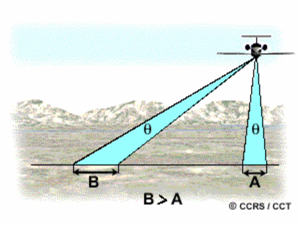
• Collects data from the point directly below the sensor (nadir), and also to each side.– Therefore the distance between the sensor in
the ground increases as the sensor moves along the scan line to each side
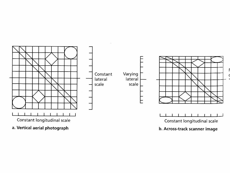
– Therefore there is and across track change in scale
Across track scanner
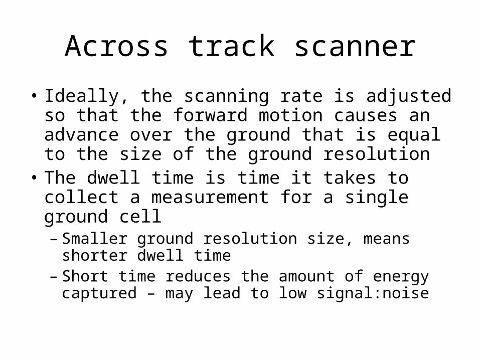
• Ideally, the scanning rate is adjusted so that the forward motion causes an advance over the ground that is equal to the size of the ground resolution
• The dwell time is time it takes to collect a measurement for a single ground cell– Smaller ground resolution size, means shorter
dwell time– Short time reduces the amount of energy
captured – may lead to low signal:noise
Across track scanner
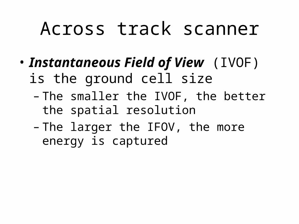
• Instantaneous Field of View (IVOF) is the ground cell size– The smaller the IVOF, the better the spatial
resolution– The larger the IFOV, the more energy is
captured

Satellites are very stable platforms, but aircraft are not. This leads to a number of distortions.
Scanner geometry is different from frame capture systems.

One-dimensional Relief Displacement
Air photo Scanner

Along-track Scanners
• Pushbroom scanners capture narrow strips of data to build up an image– No mirrors, just a line of sensors– So the entire line gets captured
simultaneously– Multiple linear arrays are used for
multispectral data (or multiple viewing directions)
Across track scanner
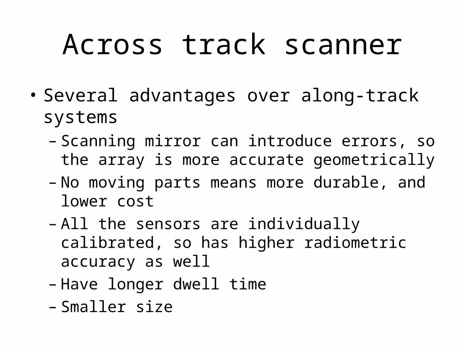
• Several advantages over along-track systems– Scanning mirror can introduce errors, so the
array is more accurate geometrically– No moving parts means more durable, and
lower cost– All the sensors are individually calibrated, so
has higher radiometric accuracy as well– Have longer dwell time– Smaller size

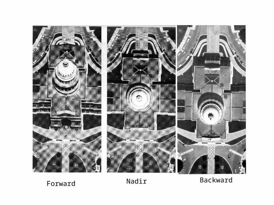
Forward Nadir Backward
Spin Scanner
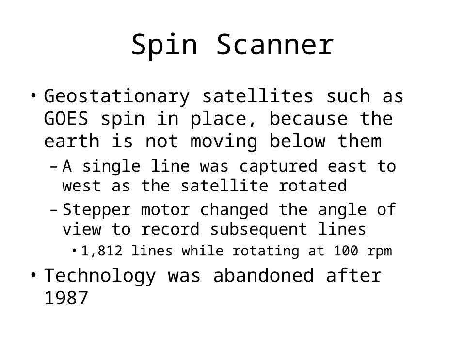
• Geostationary satellites such as GOES spin in place, because the earth is not moving below them– A single line was captured east to west as the
satellite rotated– Stepper motor changed the angle of view to
record subsequent lines• 1,812 lines while rotating at 100 rpm
• Technology was abandoned after 1987

Conical Scanner
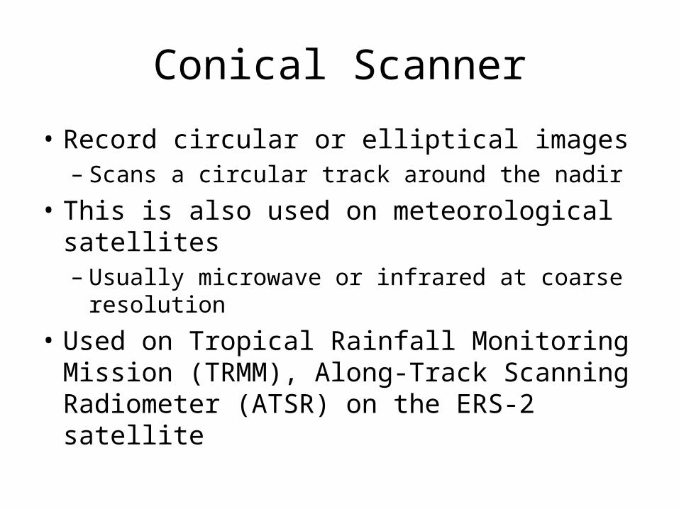
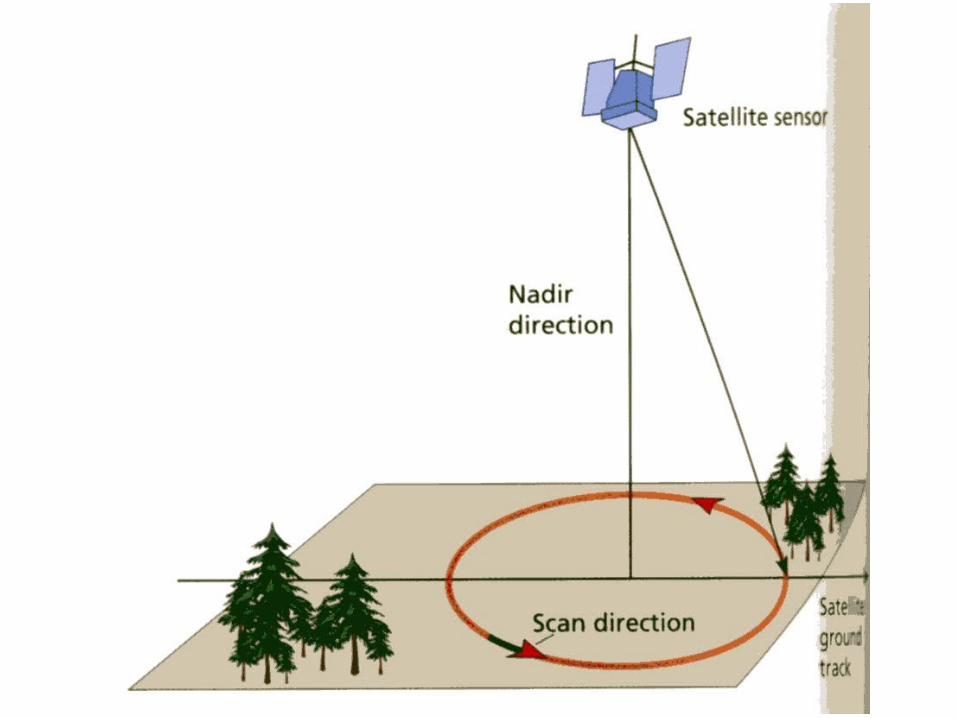
• Record circular or elliptical images – Scans a circular track around the nadir
• This is also used on meteorological satellites– Usually microwave or infrared at coarse
resolution
• Used on Tropical Rainfall Monitoring Mission (TRMM), Along-Track Scanning Radiometer (ATSR) on the ERS-2 satellite
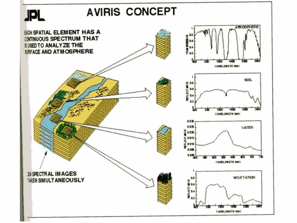
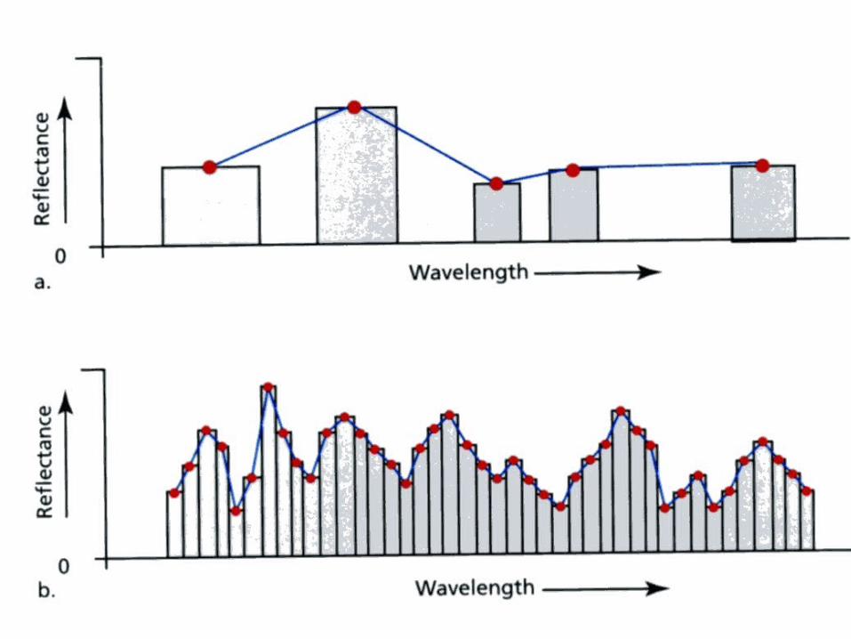
Hyperspectral Scanner
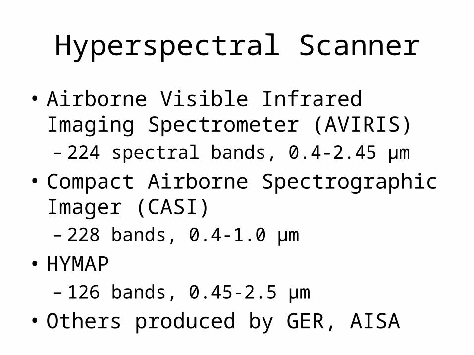
• Airborne Visible Infrared Imaging Spectrometer (AVIRIS)– 224 spectral bands, 0.4-2.45 μm
• Compact Airborne Spectrographic Imager (CASI)– 228 bands, 0.4-1.0 μm
• HYMAP– 126 bands, 0.45-2.5 μm
• Others produced by GER, AISA

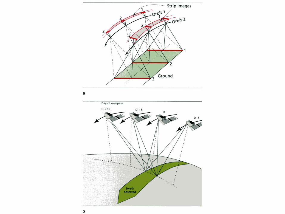
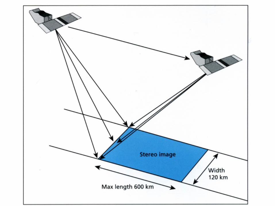
Stereo Scanner
• Like aerial photography – allows elevation data to be determined
• Must capture scene from two different angles– For nadir viewing – only overlap can be
used, and weak stereo effect
• Off-nadir viewing is better – greater relief displacements
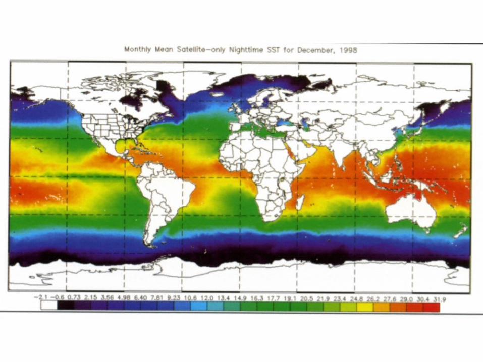
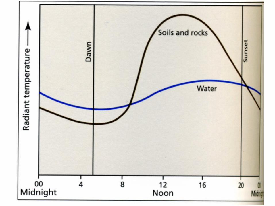
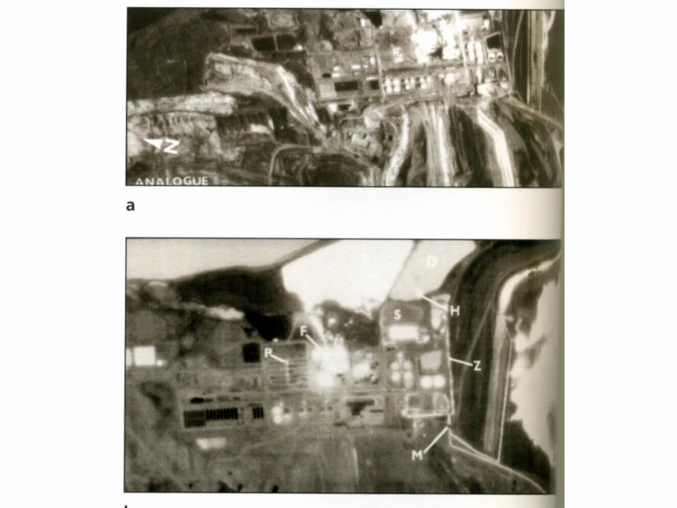
Thermal Scanner
• Thermal scanners have been applied to– military– sea surface temperature– heat loss in buildings– geologic mapping– soil moisture– soil type– fire mapping