line mount bodies - sun hydraulics · cd #999-901-105 rev. 01-jan-96 line mount bodies •aluminum...
TRANSCRIPT
11.07US Catalog 1/94 #999-001-892
CD #999-901-105 Rev. 01-Jan-96
LINE MOUNT BODIES• Aluminum rated to 3000 psi.• Ductile Iron rated to 5000 psi.
ListPrice
PartNumber
FAA/S
FAB/S
FAH/S
FAI/S
FAJ/S
FAT/S
FAU/S
ListPrice
PartNumber
FAC
FAD
FAK
FAL
FAV
FAW
ListPrice
ListPrice
0
0
T–10A CavityLocating Shoulder
Depth .06
TYPICAL CARTRIDGESUSED WITH THIS BODY
RPEC - ∗∗∗ Page 1.06RPEE - ∗∗∗ Page 1.08RDDA - ∗∗∗ Page 1.10RQEB - ∗∗∗ Page 1.12RBAC - ∗∗∗ Page 1.16
Instructions for ordering complete cartridge and bodyassemblies. Page v
Pressure ratings, materialspecifications. Page 11.02
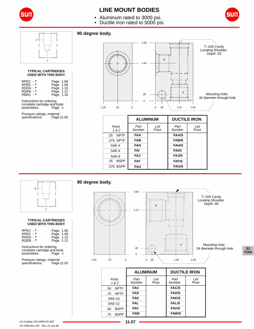
90 degree body.
PartNumber
FAA
FAB
FAH
FAI
FAJ
FAT
FAU
ALUMINUM DUCTILE IRON
.25 NPTF
.375 NPTF
SAE-4
SAE-6
SAE-8.25 BSPP
.375 BSPP
Ports 1 & 2
ALUMINUM DUCTILE IRON
.50 NPTF
.75 NPTF
SAE-10
SAE-12
.50 BSPP
.75 BSPP
Ports 1 & 2
PartNumber
FAC/S
FAD/S
FAK/S
FAL/S
FAV/S
FAW/S
1.25 .62 0 0
.28
.28
1.62
2.50
1.03 1.62
1.50 .75 0 0 .28 1.44 2.25
.28
2.12
3.00
Mounting Hole:.34 diameter through hole
T–10A CavityLocating Shoulder
Depth .03
Mounting Hole:.34 diameter through hole
2
1
2
1
90 degree body.
TYPICAL CARTRIDGESUSED WITH THIS BODY
RPEC - ∗∗∗ Page 1.06RPEE - ∗∗∗ Page 1.08RDDA - ∗∗∗ Page 1.10RQEB - ∗∗∗ Page 1.12
Instructions for ordering complete cartridge and bodyassemblies. Page v
Pressure ratings, materialspecifications. Page 11.02
S1T10A

11.08US Catalog 1/94 #999-001-892
CD #999-901-105 Rev. 01-Jan-96
LINE MOUNT BODIES• Aluminum rated to 3000 psi.• Ductile Iron rated to 5000 psi.
ListPrice
PartNumber
FCA/S
FCB/S
FCC/S
FCH/S
FCI/S
FCJ/S
FCT/S
FCU/SFCV/S
ListPrice
PartNumber
FCA
FCB
FCC
FCH
FCI
FCJ
FCT
FCUFCV
0
.31
.66
1.28
Mounting Hole:.34 diameter through hole
2.05
2.64
Inline body.
ALUMINUM DUCTILE IRON
.25 NPTF
.375 NPTF
.50 NPTF
SAE-4
SAE-6
SAE-8
.25 BSPP
.375 BSPP
.50 BSPP
Ports 1 & 2
1.19 .59 0 0 1.69 3.38
T–10A CavityLocating Shoulder
Depth .80
12TYPICAL CARTRIDGESUSED WITH THIS BODY
RPEC - ∗∗∗ Page 1.06RPEE - ∗∗∗ Page 1.08RDDA - ∗∗∗ Page 1.10RQEB - ∗∗∗ Page 1.12RBAC - ∗∗∗ Page 1.16
Instructions for ordering complete cartridge and bodyassemblies. Page v
Pressure ratings, materialspecifications. Page 11.02
S1T10A

11.09US Catalog 1/94 #999-001-892
CD #999-901-105 Rev. 01-Jan-96
ListPrice
PartNumber
FED/S
FEL/S
FEW/S
Inch
Inch
Metric
Through port body with gage port.
PartNumber
FED
FEL
FEW
.25 NPTF
.25 NPTF
.25 BSPP
.75 NPTF
SAE-12
.75 BSPP
Mounting Holes:(opposite side)
Inch: .250-20 UNC-2Bx .50 deep.
Metric: M6 x 1.00-6H x .50 deep.2 places.
T-10A CavityLocating Shoulder
Depth .03
1.75.880
.88
2.06
1.50
2.94
0
0.25.88
1.50
1.75
ListPrice
.25 NPTF
.25 NPTF
.25 NPTF
.25 NPTF
.25 NPTF
.25 NPTF
.25 BSPP
.25 BSPP
.25 BSPP
GagePort
PartNumber
FEA
FEB
FEC
FEI
FEJ
FEK
FET
FEU
FEV
ALUMINUM DUCTILE IRON
ListPrice
.25 NPTF
.375 NPTF
.50 NPTF
SAE-6
SAE-8
SAE-10
.25 BSPP
.375 BSPP
.50 BSPP
Ports 1 & 2
PartNumber
FEA/S
FEB/S
FEC/S
FEI/S
FEJ/S
FEK/S
FET/S
FEU/S
FEV/S
ListPrice
GagePort
ALUMINUM DUCTILE IRON
Ports 1 & 2
11
2
Inch
Inch
Inch
Inch
Inch
Inch
Metric
Metric
Metric
MountingHole
Dimensions
1.00 2.00
0
0.251.00
1.75
2.00 0
.88
1.62
2.25
3.25
T-10A CavityLocating Shoulder
Depth .19
MountingHole
Dimensions
2
1 1
G
G
Mounting Holes:(opposite side)
Inch: .250-20 UNC-2Bx .50 deep.
Metric: M6 x 1.00-6H x .50 deep.
2 places.
Through port body with gage port.
1.06
1.38
TYPICAL CARTRIDGESUSED WITH THIS BODY
RPEC - ∗∗∗ Page 1.06RPEE - ∗∗∗ Page 1.08RDDA - ∗∗∗ Page 1.10RQEB - ∗∗∗ Page 1.12RBAC - ∗∗∗ Page 1.16
Instructions for ordering complete cartridge and bodyassemblies. Page v
Pressure ratings, materialspecifications. Page 11.02
TYPICAL CARTRIDGESUSED WITH THIS BODY
RPEC - ∗∗∗ Page 1.06RPEE - ∗∗∗ Page 1.08RDDA - ∗∗∗ Page 1.10RQEB - ∗∗∗ Page 1.12
Instructions for ordering complete cartridge and bodyassemblies. Page v
Pressure ratings, materialspecifications. Page 11.02
LINE MOUNT BODIESl Aluminum rated to 3000 psi.
Ductile Iron rated to 5000 psi.
S1T10A
l

11.10US Catalog 1/94 #999-001-892
CD #999-901-105 Rev. 01-Jan-96
ListPrice
3.00
0
Dual through port body.
ListPrice
PartNumber
WNR/S
WNS/S
WNT/S
WNU/S
WNV/S
WNW/S
WNX/S
WNY/S
WNZ/S
PartNumber
WNR
WNS
WNT
WNU
WNV
WNW
WNX
WNY
WNZ
.25 NPTF
.375 NPTF
.50 NPTF
SAE-6
SAE-8
SAE-10
.25 BSPP
.375 BSPP
.50 BSPP
ALUMINUM DUCTILE IRON
Ports 1 & 2
2.25 1.81 .44 01.12 0
.62
1.38
2.12
.62 1.25
T–10A CavityLocating Shoulder
Depth .06
Mounting Holes:.34 diameter through hole
2 places.1 1
2 2
TYPICAL CARTRIDGESUSED WITH THIS BODY
RPEC - ∗∗∗ Page 1.06RPEE - ∗∗∗ Page 1.08RDDA - ∗∗∗ Page 1.10RQEB - ∗∗∗ Page 1.12RBAC - ∗∗∗ Page 1.16
Instructions for ordering complete cartridge and bodyassemblies. Page v
Pressure ratings, materialspecifications. Page 11.02
LINE MOUNT BODIES• Aluminum rated to 3000 psi.• Ductile Iron rated to 5000 psi.
S1T10A

11.11US Catalog 1/94 #999-001-892
CD #999-901-105 Rev. 01-Jan-96
Inch
Metric
.25 NPTF
.25 BSPP
ListPrice
ListPrice
PartNumber
FA3/S
FA3/T
PartNumber
FA3
FA3/M
ListPrice
ListPrice
PartNumber
FAO/S
FAO/T
0
.44
2.62
1.56
1.22
.75” SAE Code 624–Bolt Flange Pattern
2 places.
MountingHole
Dimensions
Inch
Metric
PartNumber
FAO
FAO/M
90 degree .75” SAE Code 61 flange port body with gage port.
.25 NPTF
.25 BSPP
GagePort
ALUMINUM DUCTILE IRON
MountingHole
DimensionsGagePort
ALUMINUM DUCTILE IRON
3.00 1.50 0 0
1.62
2.88
.34 2.09 2.44
0
.44
3.00 1.50 0 0 .34 2.09 2.441.22
T–10A CavityLocating Shoulder
Depth .38
Mounting Holes:(opposite side)
Inch: .375-16 UNC-2B x .62 deep.Metric: M10 x 1.50-6H x .62 deep.
2 places.
.75” SAE Code 614–Bolt Flange Pattern
2 places.
T–10A CavityLocating Shoulder
Depth .19
Mounting Holes:(opposite side)
Inch: .375-16 UNC-2B x .62 deep.Metric: M10 x 1.50-6H x .62 deep.
2 places.
1
2
G
1
2
G
90 degree .75” SAE Code 62 flange port body with gage port.
TYPICAL CARTRIDGESUSED WITH THIS BODY
RPEC - ∗∗∗ Page 1.06RPEE - ∗∗∗ Page 1.08RDDA - ∗∗∗ Page 1.10RQEB - ∗∗∗ Page 1.12
Instructions for ordering complete cartridge and bodyassemblies. Page v
Pressure ratings, materialspecifications. Page 11.02
SAE Specifications Page 11.03
TYPICAL CARTRIDGESUSED WITH THIS BODY
RPEC - ∗∗∗ Page 1.06RPEE - ∗∗∗ Page 1.08RDDA - ∗∗∗ Page 1.10RQEB - ∗∗∗ Page 1.12
Instructions for ordering complete cartridge and bodyassemblies. Page v
Pressure ratings, materialspecifications. Page 11.02
SAE Specifications Page 11.03
LINE MOUNT BODIES• Aluminum rated to 3000 psi.• Ductile Iron rated to 5000 psi.
S1T10A
11.12US Catalog 1/94 #999-001-892
CD #999-901-105 Rev. 01-Jan-96
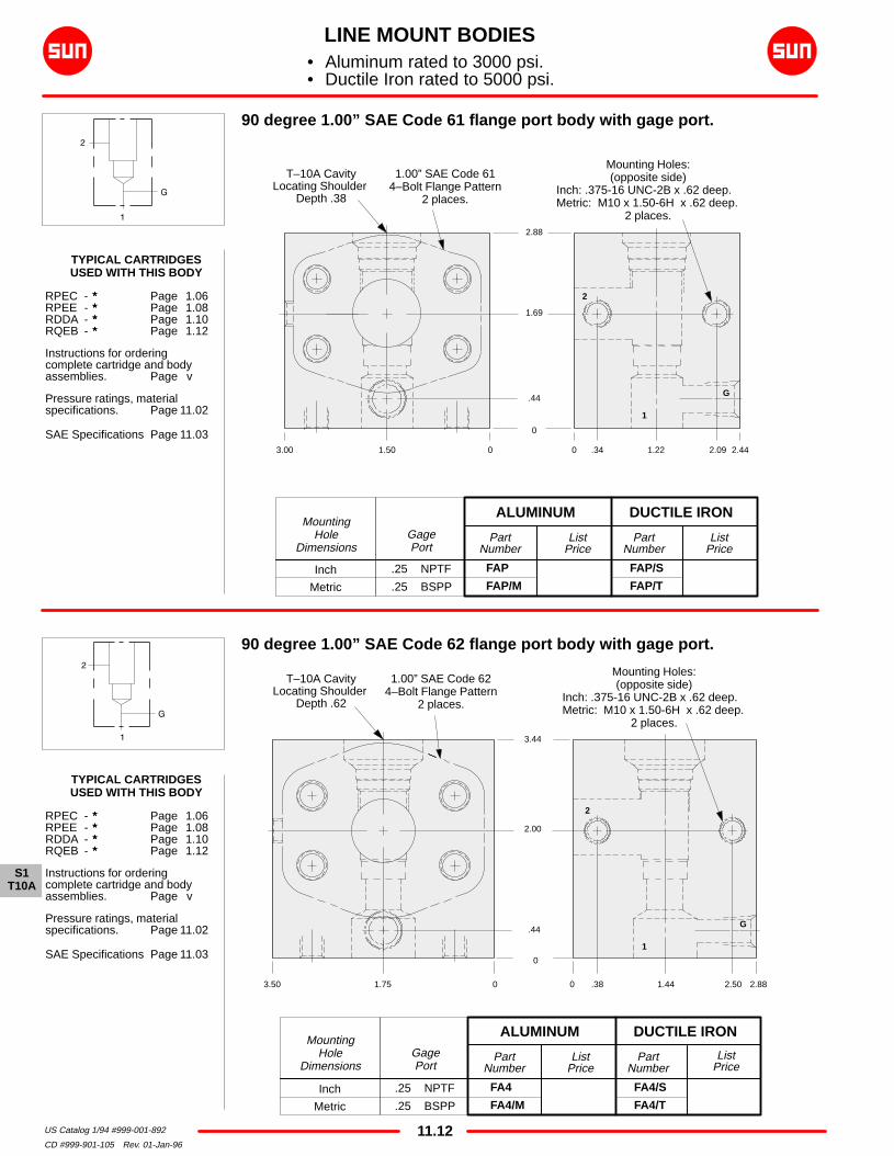
1.69
2.88
ListPrice
PartNumber
FA4/S
FA4/T
PartNumber
FA4
FA4/M
ListPrice
ListPrice
ListPrice
0
0
MountingHole
Dimensions
Inch
Metric
PartNumber
FAP
FAP/M
90 degree 1.00” SAE Code 61 flange port body with gage port.
.25 NPTF
.25 BSPP
GagePort
ALUMINUM DUCTILE IRON
PartNumber
FAP/S
FAP/T
.25 NPTF
.25 BSPP
GagePort
ALUMINUM DUCTILE IRON
3.00 1.50 0 0
.44
.34 1.22 2.09 2.44
3.50 1.75 0 0 .38 1.44 2.50 2.88
2.00
3.44
.44
T–10A CavityLocating Shoulder
Depth .62
1.00” SAE Code 624–Bolt Flange Pattern
2 places.
Mounting Holes:(opposite side)
Inch: .375-16 UNC-2B x .62 deep.Metric: M10 x 1.50-6H x .62 deep.
2 places.
T–10A CavityLocating Shoulder
Depth .38
1.00” SAE Code 614–Bolt Flange Pattern
2 places.
Mounting Holes:(opposite side)
Inch: .375-16 UNC-2B x .62 deep.Metric: M10 x 1.50-6H x .62 deep.
2 places.
1
2
G
1
2
G
90 degree 1.00” SAE Code 62 flange port body with gage port.
MountingHole
Dimensions
Inch
Metric
TYPICAL CARTRIDGESUSED WITH THIS BODY
RPEC - ∗∗∗ Page 1.06RPEE - ∗∗∗ Page 1.08RDDA - ∗∗∗ Page 1.10RQEB - ∗∗∗ Page 1.12
Instructions for ordering complete cartridge and bodyassemblies. Page v
Pressure ratings, materialspecifications. Page 11.02
SAE Specifications Page 11.03
TYPICAL CARTRIDGESUSED WITH THIS BODY
RPEC - ∗∗∗ Page 1.06RPEE - ∗∗∗ Page 1.08RDDA - ∗∗∗ Page 1.10RQEB - ∗∗∗ Page 1.12
Instructions for ordering complete cartridge and bodyassemblies. Page v
Pressure ratings, materialspecifications. Page 11.02
SAE Specifications Page 11.03
LINE MOUNT BODIES• Aluminum rated to 3000 psi.• Ductile Iron rated to 5000 psi.
S1T10A

11.13US Catalog 1/94 #999-001-892
CD #999-901-105 Rev. 01-Jan-96
Sandwich mount through port .75” SAE Code 61 body with gage port.
ListPrice
PartNumber
ZQN/S
ZQM/SInch
Metric
.25 NPTF
.25 BSPP
SAE-10
.50 BSPP
Port 2GagePort
ListPrice
PartNumber
ZQN
ZQM
ALUMINUM DUCTILE IRON
.75” SAE Code 614–Bolt Flange
Pattern
T–10A CavityLocating Shoulder
Depth .06
1
2 2
G
2.00 1.00 0 0
0
.69 1.94
1.75
3.69
4.62
MountingHole
Dimensions
0
PartNumber
ZDG/S
ZDJ/S
ZDD/S
ListPrice
ListPrice
T–10A CavityLocating Shoulder
Depth .06
PartNumber
ZDG
ZDJ
ZDD
SAE-10
.50 NPTF
.50 BSPP
Ports 1 & 2
.25 NPTF
.25 NPTF
.25 BSPP
GagePort
ALUMINUM DUCTILE IRON
2.00 1.00 0 0
1.75
.69
3.69
4.62
.75” SAE Code 614–Bolt Flange PatternCounterbore .34 deep.
1
G
2 2
1.28 1.94
Inch
Inch
Metric
MountingHole
Dimensions
1.28
Flange mount through port .75” SAE Code 61 body with threaded outletand gage port.
TYPICAL CARTRIDGESUSED WITH THIS BODY
RPEC - ∗∗∗ Page 1.06RPEE - ∗∗∗ Page 1.08RDDA - ∗∗∗ Page 1.10RQEB - ∗∗∗ Page 1.12
Cartridge seal type determinesO–ring type.
Instructions for ordering complete cartridge and bodyassemblies. Page v
Pressure ratings, materialspecifications. Page 11.02
SAE Specifications Page 11.03
–214 O–ring
–214 O–ring
LINE MOUNT BODIES• Aluminum rated to 3000 psi.• Ductile Iron rated to 5000 psi.
S1T10A

11.14US Catalog 1/94 #999-001-892
CD #999-901-105 Rev. 01-Jan-96
SAE-12
SAE-10
.75 NPTF
.50 NPTF
.75 BSPP
.50 BSPP
.75” SAE Code 614–Bolt Flange Pattern
ListPrice
PartNumber
ZCW/S
ZCX/S
ZCY/S
ZCZ/S
ZCT/S
ZCV/T
ListPrice
PartNumber
ZCW
ZCX
ZCY
ZCZ
ZCT
ZCV/M
4.75
Port 2 GagePort
ALUMINUM DUCTILE IRON
.25 NPTF
.25 NPTF
.25 NPTF
.25 NPTF
.25 BSPP
.25 BSPP
2.50 1.25 0 0
0
1.81
3.84
.88 1.44 2.44
T–10A CavityLocating Shoulder
Depth .06
Sandwich mount through port .75” SAE Code 62 body with gage port.
.75” SAE Code 624–Bolt Flange Pattern
2
1
G
0
Sandwich mount through port .75” SAE Code 61 body with gage port.
Port 2
SAE-12
.75 NPTF
.75 BSPP
Inch
Inch
Metric
MountingHole
DimensionsList
PricePart
Number
ZHB
ZHC
ZGZ
ALUMINUM DUCTILE IRON
ListPrice
GagePort
.25 NPTF
.25 NPTF
.25 BSPP
PartNumber
ZHB/S
ZHC/S
ZGZ/S
001.252.50 .69 1.94
1.75
3.75
4.62
0 1.35.75
T–10A CavityLocating Shoulder
Depth .062
1
2 2
G
2
Inch
Inch
Inch
Inch
Metric
Metric
MountingHole
Dimensions
TYPICAL CARTRIDGESUSED WITH THIS BODY
RPEC - ∗∗∗ Page 1.06RPEE - ∗∗∗ Page 1.08RDDA - ∗∗∗ Page 1.10RQEB - ∗∗∗ Page 1.12
Cartridge seal type determinesO–ring type.
Instructions for ordering complete cartridge and bodyassemblies. Page v
Pressure ratings, materialspecifications. Page 11.02
SAE Specifications Page 11.03
–214 O–ring
–214 O–ring
LINE MOUNT BODIES• Aluminum rated to 3000 psi.• Ductile Iron rated to 5000 psi.
S1T10A

11.15US Catalog 1/94 #999-001-892
CD #999-901-105a Rev. 01-Jan-95
ListPrice
PartNumber
ZCP/S
ZCQ/S
ZCR/S
ZCS/S
ZCM/S
ZCN/S
T–10A CavityLocating Shoulder
Depth .06
Flange mount through port .75” SAE Code 62 body with threaded outletand gage port.
1.44
SAE-12
SAE-10
.75 NPTF
.50 NPTF
.75 BSPP
.50 BSPP
Ports 1 & 2
.25 NPTF
.25 NPTF
.25 NPTF
.25 NPTF
.25 BSPP
.25 BSPP
GagePort
ListPrice
PartNumber
ZCP
ZCQ
ZCR
ZCS
ZCM
ZCN
ALUMINUM DUCTILE IRON
1.81
3.84
4.75
2.441.25 0 0 .882.50
0
2 2
1
–214 O–ring
ListPrice
PartNumber
ZDF/S
ZDH/S
ZDC/S
Inch
Inch
Metric
3.75
0
SAE-12
.75 NPTF
.75 BSPP
Ports 1 & 2
.25 NPTF
.25 NPTF
.25 BSPP
GagePort
ListPrice
PartNumber
ZDF
ZDH
ZDC
ALUMINUM DUCTILE IRONMounting
HoleDimensions
2.50 1.25 0 0
1.75
4.62
.69 1.94
2 2
1
T–10A CavityLocating Shoulder
Depth .06
G
Flange mount through port .75” SAE Code 61 body with threaded outletand gage port.
1.35
.75” SAE Code 614–Bolt Flange PatternCounterbore .34 deep.
G
Inch
Inch
Inch
Inch
Metric
Metric
MountingHole
Dimensions
.75” SAE Code 624–Bolt Flange PatternCounterbore .34 deep.
TYPICAL CARTRIDGESUSED WITH THIS BODY
RPEC - ∗∗∗ Page 1.06RPEE - ∗∗∗ Page 1.08RDDA - ∗∗∗ Page 1.10RQEB - ∗∗∗ Page 1.12
Cartridge seal type determinesO–ring type.
Instructions for ordering complete cartridge and bodyassemblies. Page v
Pressure ratings, materialspecifications. Page 11.02
SAE Specifications Page 11.03
–214 O–ring
LINE MOUNT BODIES• Aluminum rated to 3000 psi.• Ductile Iron rated to 5000 psi.
S1T10A

11.16US Catalog 1/94 #999-001-892
CD #999-901-105 Rev. 01-Jan-96
T–10A CavityLocating Shoulder
Depth .122 places.
TYPICAL CARTRIDGESUSED WITH THIS BODY
RPEC - ∗∗∗ Page 1.06RPEE - ∗∗∗ Page 1.08RDDA - ∗∗∗ Page 1.10RQEB - ∗∗∗ Page 1.12
Instructions for ordering complete cartridge and bodyassemblies. Page v
Pressure ratings, materialspecifications. Page 11.02
TYPICAL CARTRIDGESUSED WITH THIS BODY
RPEC - ∗∗∗ Page 1.06RPEE - ∗∗∗ Page 1.08RDDA - ∗∗∗ Page 1.10RQEB - ∗∗∗ Page 1.12
Instructions for ordering complete cartridge and bodyassemblies. Page v
Pressure ratings, materialspecifications. Page 11.02
ListPrice
ListPrice
ListPrice
PartNumber
YFA
YFB
YFC
YFH
YFI
YFJ
YFK
YFTYFU
YFV
Two cavity body for cross–port relief applications.
Two cavity body for cross–port relief applications.
PartNumber
YFD/S
YFE/S
YFL/S
YFM/S
YFW/S
YFX/S
Ports 1 & 2
PartNumber
YFD
YFE
YFL
YFM
YFW
YFX
.75 NPTF
1.00 NPTF
SAE-12
SAE-16
.75 BSPP
1.00 BSPP
.25 NPTF
.375 NPTF
.50 NPTF
SAE-4
SAE-6
SAE-8
SAE-10
.25 BSPP
.375 BSPP
.50 BSPP
ListPrice
ALUMINUM DUCTILE IRON
Ports 1 & 2
ALUMINUM DUCTILE IRON
3.50
3.00
2.00
1.50
.50
0
2.00 1.41 1.00 .59 0 0 .94 1.97 3.00 3.94
1
1
2
2
Mounting Holes:.34 diameter through hole
2 places.
0 0
0
.44
1.09
1.66
2.31
2.75
.56.94.75
1.50 .97 1.75 2.53 3.50
T–10A CavityLocating Shoulder
Depth .122 places.
Mounting Holes:.34 diameter through hole
2 places.
1
12
2
PartNumber
YFA/S
YFB/S
YFC/S
YFH/S
YFI/S
YFJ/S
YFK/S
YFT/SYFU/S
YFV/S
LINE MOUNT BODIES• Aluminum rated to 3000 psi.• Ductile Iron rated to 5000 psi.
S1T10A

11.17US Catalog 1/94 #999-001-892
CD #999-901-105 Rev. 01-Jan-96
T–10A CavityLocating Shoulder
Depth .312 places.
0
T–10A CavityLocating Shoulder
Depth .162 places.
ListPrice
ListPrice
2.94
2.47
0
G1
1
MountingHole
Dimensions
Inch
Metric
PartNumber
YFO
YFO/M
Two cavity .75” SAE Code 61 flange port body for cross–port reliefapplications.
.25 NPTF
.25 BSPP
PortsG1 & G2
ALUMINUM DUCTILE IRON
PartNumber
YFO/S
YFO/T
MountingHole
Dimensions
Inch
Metric
PartNumber
YF3
YF3/M
ListPrice
.25 NPTF
.25 BSPP
PortsG1 & G2
ALUMINUM DUCTILE IRON
ListPrice
PartNumber
YF3/S
YF3/T
1 2
2
G2
Mounting Holes:(opposite side)
Inch: .375-16 UNC-2B x .62 deepMetric: M10 x 1.50-6H x .62 deep
2 places.
.75” SAE Code 614–Bolt Flange Pattern
4 places.
.47
1.00
1.47
1.94
2.47
2.94
3.00
1.721.501.28
0
0 2.12 4.25
Mounting Holes:(opposite side)
Inch: .375-16 UNC-2B x .62 deepMetric: M10 x 1.50-6H x .62 deep
2 places.
.75” SAE Code 624–Bolt Flange Pattern
4 places.
0
0 2.50 5.00
1.00
1.50
1.94
3.00
1.47
.47
1.72
1.28
1
1
2
2
G1 G2
1.03 3.22
1.19 3.81
Two cavity .75” SAE Code 62 flange port body for cross–port reliefapplications.
TYPICAL CARTRIDGESUSED WITH THIS BODY
RPEC - ∗∗∗ Page 1.06RPEE - ∗∗∗ Page 1.08RDDA - ∗∗∗ Page 1.10RQEB - ∗∗∗ Page 1.12
Instructions for ordering complete cartridge and bodyassemblies. Page v
Pressure ratings, materialspecifications. Page 11.02
SAE Specifications Page 11.03
TYPICAL CARTRIDGESUSED WITH THIS BODY
RPEC - ∗∗∗ Page 1.06RPEE - ∗∗∗ Page 1.08RDDA - ∗∗∗ Page 1.10RQEB - ∗∗∗ Page 1.12
Instructions for ordering complete cartridge and bodyassemblies. Page v
Pressure ratings, materialspecifications. Page 11.02
SAE Specifications Page 11.03
LINE MOUNT BODIES• Aluminum rated to 3000 psi.• Ductile Iron rated to 5000 psi.
S1T10A

11.18US Catalog 1/94 #999-001-892
CD #999-901-105 Rev. 01-Jan-96
11.00” SAE Code 61
4–Bolt Flange Pattern4 places.
ListPrice
PartNumber
YF4/S
YF4/T
PartNumber
YF4
YF4/M
ListPrice
ListPrice
Two cavity 1.00” SAE Code 62 flange port body with gage port forcross–port relief applications.
PartNumber
YFP
YFP/M.25 NPTF
.25 BSPP
PortsG1 & G2
ALUMINUM DUCTILE IRON
ListPrice
PartNumber
YFP/S
YFP/T
.25 NPTF
.25 BSPP
PortsG1 & G2
ALUMINUM DUCTILE IRON
2.94
2.47
1.81
1.47
.47
0
4.00
2.38
2.00
1.63
0
1.38 2.88 4.38 5.750
1.00” SAE Code 624–Bolt Flange Pattern
4 places.
T–10A CavityLocating Shoulder
Depth .562 places.
Mounting Holes:(opposite side)
Inch: .375-16 UNC-2B x .62 deepMetric: M10 x 1.50-6H x .62 deep
2 places.
Inch
Metric
MountingHole
Dimensions
Inch
Metric
MountingHole
Dimensions
1
2
G1 G2
2
1
1.12
Two cavity 1.00” SAE Code 61 flange port body with gage port forcross–port relief applications.
T–10A CavityLocating Shoulder
Depth .342 places.
2.94
2.47
1.78
1.47
.47
0
3.00
1.50
1.16
0
1.16
1.16 2.38 3.59 4.750
1.84
Mounting Holes:(opposite side)
Inch: .375-16 UNC-2B x .62 deepMetric: M10 x 1.50-6H x .62 deep
2 places.
1 2
2
G1 G2
1
TYPICAL CARTRIDGESUSED WITH THIS BODY
RPEC - ∗∗∗ Page 1.06RPEE - ∗∗∗ Page 1.08RDDA - ∗∗∗ Page 1.10RQEB - ∗∗∗ Page 1.12
Instructions for ordering complete cartridge and bodyassemblies. Page v
Pressure ratings, materialspecifications. Page 11.02
SAE Specifications Page 11.03
TYPICAL CARTRIDGESUSED WITH THIS BODY
RPEC - ∗∗∗ Page 1.06RPEE - ∗∗∗ Page 1.08RDDA - ∗∗∗ Page 1.10RQEB - ∗∗∗ Page 1.12
Instructions for ordering complete cartridge and bodyassemblies. Page v
Pressure ratings, materialspecifications. Page 11.02
SAE Specifications Page 11.03
LINE MOUNT BODIES• Aluminum rated to 3000 psi.• Ductile Iron rated to 5000 psi.
S1T10A

11.19US Catalog 1/94 #999-001-892
CD #999-901-105 Rev. 01-Jan-96
ListPrice
ListPrice
PartNumber
FNA/S
FNB/S
FNC/S
FNI/S
FNJ/S
FNK/S
FNT/S
FNU/SFNV/S
ListPrice
PartNumber
FNA
FNB
FNC
FNI
FNJ
FNK
FNT
FNUFNV
Body with reverse free flow check.
Two cavity body with make–up checks for cross–port relief applications.
ListPrice
PartNumber
FMA
FMB
FMC
FMI
FMJFMK
FMT
FMU
FMV
ALUMINUM DUCTILE IRON
.25 NPTF
.375 NPTF
.50 NPTF
SAE-6
SAE-8
SAE-10
.25 BSPP
.375 BSPP
.50 BSPP
Ports 1 & 2 & T
ALUMINUM DUCTILE IRON
.25 NPTF
.375 NPTF
.50 NPTF
SAE-6
SAE-8
SAE-10
.25 BSPP
.375 BSPP
.50 BSPP
Ports 1 & 2
Mounting Holes:.42 diameter through hole
2 places.
T–10A CavityLocating Shoulder
Depth .032 places.
ÁÁÁÁ
ÁÁÁÁÁÁÁ
ÁÁÁÁ0
00.621.25
.25
.91
3.00
.25 2.25
0 2.50 0
2.12
0
.62.75 T–10A CavityLocating Shoulder
Depth .03
Mounting Holes:.28 diameter through hole.
2 places..59
1
2
0
0
2.78
1.59
.41
0
.75
.87
1.562.38
3.00
.912.192.94 0 1.09 2.09 3.19
.72
1
2 2
1
T
CXDA-XAN
CXDA-XAN2 places
TYPICAL CARTRIDGESUSED WITH THIS BODY
RPEC - ∗∗∗ Page 1.06RPEE - ∗∗∗ Page 1.08RDDA - ∗∗∗ Page 1.10RQEB - ∗∗∗ Page 1.12RBAC - ∗∗∗ Page 1.16
Cartridge seal type determinescheck valve seal type.
Instructions for ordering complete cartridge and bodyassemblies. Page v
Pressure ratings, materialspecifications. Page 11.02
TYPICAL CARTRIDGESUSED WITH THIS BODY
RPEC - ∗∗∗ Page 1.06RPEE - ∗∗∗ Page 1.08RDDA - ∗∗∗ Page 1.10RQEB - ∗∗∗ Page 1.12
Cartridge seal type determinescheck valve seal type.
Instructions for ordering complete cartridge and bodyassemblies. Page v
Pressure ratings, materialspecifications. Page 11.02
PartNumber
FMA/S
FMB/S
FMC/S
FMI/S
FMJ/SFMK/S
FMT/S
FMU/S
FMV/S
LINE MOUNT BODIES• Aluminum rated to 3000 psi.• Ductile Iron rated to 5000 psi.
S1T10A