line extension rules and regulations - pine...
TRANSCRIPT
LINE EXTENSION RULES AND REGULATIONS
If you have any specific questions or concerns, you may call the office. Developers and engineers should be aware that a $100.00 Plan Review Fee is payable when plans are submitted for review. Prior to GPIWA signing a DEP permit form, the following capital charge collection policy must be followed:
"Policy adoption and the definition of terms contained within shall be governed by the Greater Pine Island Water Association, Inc. (GPIWA) Rules and Regulations (January 12, 2000) and as hereinafter amended.
Owners, Developers, Contractors, etc. that request GPIWA execute the required Florida Department of Environmental Protection (FDEP) form 62-555.900(7), “Notice of Intent to Use The General Permit For Construction of Water Main Extensions for PWS’s” or its successor form(s) (Permit), shall pay to the GPIWA fifty percent (50%) of the total of all Capital Charges that are normal and customarily generated by the unit(s) defined within the Permit. Such charges shall be paid to the Association prior to the execution of the Permit by GPIWA staff. Capital Charges shall be calculated based on the GPIWA Schedule of Fees and Water Rates in existence at the time of application.
The balance of the Capital Charges (the remaining fifty percent), shall become due and payable on a per unit basis along with all other customary fees and charges due when formal application for water service is made to GPIWA.
Policy approved by the GPIWA Board of Directors and effective and incorporated into the Greater Pine Island Water Association, Inc. Rules and Regulations this 22nd day of June, 2004."
Call the GPIWA Business Office for the current capital charge fee.
DEVELOPMENT HANDBOOK
New Construction Policy
Construction Specifications
Forms and Fees
5281 Pine Island Road, Bokeelia, Florida 33922
Phone: (239) 283-1071 Fax: (239) 283-7792 www.pineislandwater.com
Revised: March 2004 June 2005 October 2008 August, 2012 November, 2012 November, 2013
TABLE OF CONTENTS
NEW CONSTRUCTION POLICY - GENERAL Page 1 - 4 INTRODUCTION PRELIMINARY PLANNING RESERVATION OF CAPACITY – CAPITAL CHARGES PRE-CONSTRUCTION MEETING CONSTRUCTION INSPECTIONS EASEMENTS RIGHTS OF INGRESS AND EGRESS DEDICATION OF WATER FACILITIES APPLICATION FOR SERVICE
TECHNICAL SPECIFICATIONS PAGE
GENERAL 05
MATERIAL NSF- ANSI 05
WATER MAINS 05 ROAD CROSSINGS 06 PIPE MATERIAL – GENERAL 06 PIPE JOINTING 06 VALVES 07 VALVE BOXES 07 WATER SERVICES – GENERAL 07 WATER SERVICES – SPECIFICATIONS 08 Location Tapping Saddles Ball Corporation Stop Curb Stops Service Lines FIRE HYDRANTS 09 FIRE LINES 09 JACK AND BORE 09 RESTRAINTS 09 WATER FOR CONSTRUCTION 09 MISCELLANEOUS INF0RMATION 10 LOCAL STANDARDS 10 EXISTING IMPROVEMENTS 10
Table of Contents – Continued
INTERRUPTION OF SERVICE 11
PROTECTION OF PIPING IN FILL 11
TRENCHING AND BACKFILLING 11-13
General
Width of Trench
Shoring and Bracing
Water removal
Disposition of Utilities
Grading Trench Bottom
Tree Protection
Backfilling
BACKFLOW PREVENTION 14
WATER DISTRIBUTION MAIN INSTALLATION
CONNECTIONS TO EXISTING MAINS 15
HANDLING AND STORING MATERIAL 15
IDENTIFICATION 15
PIPE LAYING – GENERAL 15
Pipe Laying and Jointing 16
Fittings and branch connections 16
Setting Valves 16
Blocking 16
Tests - Hydrostatic 16
Flushing Mains 17
Sterilization of Mains 17
Obstructions 17
Damage to Existing Structure and Utilities 18
Notification Requirement 18
As-built 18
FINAL INSPECTION 18

Table of Contents – Continued
APPENDIX
“A “ APPLICATION TO CONSTRUCT 19
“B” PRECONSTRUCTION MEETING CHECKLIST 22
“C” FIRE HYDRANT SPECIFICATIONS 24
“D” DEDICATION OF WATER LINES
Submittal Package 26-27
Cover Letter
FDEP Application to Approve for Service
FDEP Letter Certifying Completion (OK to Use)
Bill of Sale
Affidavit of No Liens
One-Year Warranty
Material/Cost Breakdown
Engineer Certification of Pipe Quantities Installed
Engineer Certification of Pressure Tests
Copies of Bacteriological Tests
Easements
As-Built Requirements
CADD Disk
“E” BILL OF SALE 28
“F” WARRANTY/GUARANTY 30
“G” OWNERS AFFIDAVIT OF NO LIENS 31
“H” GRANT OF UTILITY EASEMENT 33
“I” HYDROSTATIC TEST RESULTS 35
DRAWINGS Begin Page 36

INTRODUCTION The purpose of this document is to provide technical and procedural guidelines for the construction of multiple service connections, water mains, and/or other water infrastructure or facilities to be dedicated to the Greater Pine Island Water Association, Inc. (GPIWA). The document should serve as a guideline for developers, engineers, contractors, and other design professionals. The intent of this manual is to maintain consistency with all local, state, and federal regulations and does not preclude compliance with SFWMD, FDEP, USACOE, DNR, Lee County Development Standards, and the Lee County Utilities Manual.
Technical specifications and details have been provided only in specific instances where GPIWA requirements differ from Lee County Standards. All other provisions of the Lee County manual apply. Design professionals should be aware of these minor differences before specifying water service in the GPIWA franchise area. Any deviations with the technical specifications and details or conflicts with local codes and ordinances should be noted prior to plan submittal. PRELIMINARY PLANNING Developers, Owners, Contractors, and others (Developers) wishing to add infrastructure to the GPIWA water system should contact the Association’s Office Manager to confirm that water service is available from GPIWA and pick-up a copy of GPIWA’s “Application to Construct”. If the Developer wishes to move forward with his/her project, The Application to Construct (appendix “A”) should be filled out and submitted to the GPIWA offices with preliminary plans, drawings and/or specifications, along with a non-refundable $100.00 Plan Review Fee. Plans at this stage will be considered 60% complete by GPIWA. Upon receiving the application the General Manager, (usually within two weeks) will have the application reviewed by GPIWA management and staff. Once reviewed, comments and corrections shall be sent back to the Developer/Engineer. Plan corrections should be made based on the initial GPIWA plan review and a sent back to GPIWA. Plans at this point shall be considered 90% complete. GPIWA will perform a final plan review at this point and forward any additional comments back to the developer. Incorporating these final comments into the development plans, will bring the plans to the 100% approval level. Three (3) copies of the Final Plans should be submitted to GPIWA with the developers request to have Florida DEP form 62-555.900(7), “Notice of Intent to Use the General Permit for Construction of Water Main Extensions. GPIWA requires up to 14-days to review the final plans and execute the Florida DEP form. Reservation of Capacity – Capital Charges The Developer shall pay to GPIWA fifty percent (50%) of the Capital Charges calculated for the Development prior to the execution of the FDEP form 62-555.900(7), which effectively reserves water system capacity for the development. GPIWA’s Office Manager should be contacted for a determination of the actual dollar amount.
Pre-Construction Meeting The Developer may schedule a pre-construction meeting with the GPIWA staff after FDEP has approved the ”General Permit to Construct” application (62-555.900(7). A copy of the approved FDEP permit for general utility construction should be given to GPIWA at this time (if not previously forwarded). Appendix B is a listing of preconstruction topics and milestones that require notification and inspection during the course of construction. Following a successful pre-construction meeting, and payment of a $25.00/unit Construction Inspection Fee, a “Notice to Proceed” will be issued. Construction The Developer shall be responsible for engineering, construction and permitting for all on-site infrastructure. This document shall be the controlling document for construction specifications. Upon completion of the project, ownership of all on-site water infrastructures shall be dedicated to the Association; such infrastructure shall have a one (1) year unlimited warranty for parts and labor. The Developer shall also be responsible for all off-site engineering, construction and permitting (up to and including the physical connection) needed to connect to the Association’s infrastructure to the Developer’s infrastructure. Upon completion of the project ownership of all off-site water infrastructures shall be dedicated to the Association. Such infrastructure shall have a one (1) year unlimited warranty for parts and labor. Joint Participation Agreement If during the planning process, GPIWA wishes to upgrade the Developer’s proposed infrastructure, and that upgrade will solely benefit GPIWA, the Developer shall negotiate in good faith and make available pricing that will allow the Developer’s contractor to make the upgrades at the expense of GPIWA. Inspections Exposing, tampering with, including making connections to the GPIWA water system, without notifying a GPIWA representative to be on-site to observe, is a Federal Offense. The GPIWA General Manager must be notified at least two working days in advance so that arrangements can be made for an Association employee to be on-site whenever a physical connection is made to the GPIWA water system. No physical contact shall be made with existing GPIWA water system infrastructure unless supervised by an employee of GPIWA. In addition, the Association reserves the right to inspect any supplies, materials, appearances, construction technique, and/or installations for the project. GPIWA personnel shall be present during all hydrostatic testing (Form Appendix “D”) of pipe and/or fittings if the test is to be considered valid. The Developer shall also be responsible for all required bacteria testing and/or main line clearances. In addition, GPIWA reserves the right to enter the construction area at anytime during construction to inspect the placement of appurtenances to be dedicated to the Association.
Easements

Through the dedication process, the Developer will grant and convey to the Association, its successors and assigns the non-exclusive right or privilege to maintain water facilities in, under, upon, over, and across those portions of the Developer’s Property. In accordance therewith, the Developer agrees to execute specific easement agreements to be recorded in the public records.
For dedicated easement contained on private property, repair/replacement maintenance of any water infrastructure associated with the project shall be limited to the excavation, repair/replacement, backfilling and/or compaction within the easement repair site. Repair/replacement of any disturbed, broken or removed concrete, asphalt, landscaping, irrigation, signs, parking structure, lighting, stanchions, mail boxes, and like structure shall be the responsibility of the Developer or the owner/successor. Rights of Ingress and Egress The foregoing grants include the necessary right of ingress and egress to any part of developer’s property upon which Association is operating, or maintaining water facilities.
Dedication of Water Facilities
Upon project completion, the Developer will dedicate the constructed water lines, facilities, and/or infrastructure to the D. Water service will not be provided until all items are complete. Association. Items to be submitted by the project Engineer are included in Appendix
Application for Service Once the facilities are dedicated, the Developer or its successors or occupant(s) of Developer’s Property, shall make written application through the Associations Office Manager for the opening of an account(s) for service. At the time of application for service, the applicant must become a member of the Association and pay all requisite service charges
TECHNICAL SPECIFICATIONS
GENERAL: Plans must show proposed lines (location, size, type of pipe, etc). They must also show location of valves, fire hydrants, etc. Upon approval, the plans will be returned to the developer, one (1) set will be retained by GPIWA. Standard details included in this manual must be included in Engineer's plan sets. A licensed Contractor shall be utilized for all water main extensions to be dedicated to GPIWA. MATERIAL: All materials must used must meet or exceed the appropriate NSF/ANSI 60 (chemicals), NSF/ANSI 61 (Drinking Water Components), NSF/ANSI 14 (Plastic Piping Components and Materials). In
addition, AWWA, GPIWA, and/or Lee County specifications, for materials and construction, where appropriate, must be observed.
WATER MAINS: Minimum water main size will be dictated by Lee County Development Standards. Minimum main size for feeding a fire hydrant in the GPIWA system is six inch (6"). Water mains shall be AWWA C-900, DR18, rubber-gasketed pipe with bell and spigot ends. 3" and smaller lines shall be Schedule 40, PVC rubber-gasketed pipe with bell and spigot ends. NOTE: A two-inch (2") water line may serve a maximum of five (5) residential lots. ROAD CROSSINGS: All water mains that are placed under concrete or asphalt must be sleeved. Carrier pipe may be DIP, PVC or HDPE. Casing shall extend a minimum of five (5) feet past roadway edges. DIP – shall meet the requirements of ASTM A 139, Grade B, with the following wall thickness: 4” – 20” .250 inches
20” – 30” .312 Inches
PVC – DR 14, C-900 HDPE – SDR - 11 At a minimum, all casing pipe shall be twice the diameter of the carrier pipe. PIPE MATERIAL - GENERAL: No Ductile Iron pipe shall be used to transmit water in the GPIWA System. All pipe used to carry water shall meet NSF/ANSI-14 standards. PVC pressure pipe for main lines four(4) inches in diameter and greater shall conform to AWWA C-900 and be pressure class 200 psi (DR-18). All PVC pressure pipe smaller than four (4) inches in diameter shall be Schedule 40, (SDR 21, PR200) and shall conform to ASTM D2241. Solvent cement joints shall not be used on any mainline. All materials shall be in accordance with AWWA C-900 and ASTM D2241. All service piping ( under 2”) shall be Copper Tube Size (CTS) Polyethylene with a working pressure of 200 PSI and conform to AWWA C901, ASTM3350 and ASTM2737. PIPE JOINTING: Materials and methods shall be in strict accord with the recommendations of the respective pipe manufacturer. VALVES: Gate valves 2" to 3" shall be resilient seat iron body, bronze mounted, non-rising stem type with 0-ring stem seals. Gate valves 4" and larger shall be Tyler DRS 250 or approved equal iron body,
resilient seat type in accordance with AWWA C509, with non-rising stem and 0-ring stem seals. All valves shall have a 2" square nut operator. Valves shall meet applicable AWWA Standards. VALVE BOXES: Valve boxes shall comply with the following requirements: For 2" and larger valves, boxes shall be approved standard Buffalo type, cast iron, adjustable shaft boxes having a minimum shaft diameter of 5-1/4". The castings shall be coated with two coats of coat-tar pitch varnish. The lids of all boxes shall bear the word "Water" or the letter "W". Lids shall be painted blue, except for hydrant valves which shall have the lids painted red. WATER SERVICES – GENERAL (DWG 15 & 16) The Developer shall be responsible for the placement of a water service and meter box at each location at which a water meter will be needed. Detail w-15 and 16 include the specifications for water service taps and associated appurtenances. Service lines shall be run to all lots and installed in such a manner so that two lots may be serviced from one location. Water Services shall consist of the following: stainless tapping saddle, corporation stop, service line, curbstop and meter box. Owner shall be responsible for relocation in the event of grade changes. The minimum size water service line shall be 1". No more than 2 - 5/8” meters may be served by a 1" service line. Water service lines located under a asphalt or concrete shall be sleeved. Carrier Pipe specifications are defined in “Road Crossing” section.
WATER SERVICES – SPECIFICATIONS
LOCATION
Services shall be placed in the utility easement 1-foot inside property corner and extend a minimum of 2’ above finish lot grade and placed in meter box, DPW Model D1200 or approved equal.
TAPPING SADDLES:
Tapping saddles shall be stainless steel, Romac Style 306, or approved equal.
Hot taps for 1½” services shall be 2” with a 2” operation nut on the valve and then reduced to 1½”.
All services for 1½" or 2" meters shall be 2" service lines.

BALL CORPORATION STOP
Ball Corporation stops shall be Ford FB-500, or approved equal. CURB STOPS: Angle stops will be Ford B43-342W with padlock wings.
SERVICE LINES: Service lines will be Schedule 40 PVC pipe. Pipe will be capped and marked from the main to the cap with blue tape. Pipe will be staked with a two-by-four, 2’ above finish grade and left staked until meter box or vault is installed to finish grade. All PVC service lines will have detection tape. Detection tape will tie back to main line detection tape. NOTE: The above items are specified exactly in order to maintain standardization throughout the system.
FIRE HYDRANTS: (DWG W 2 thru 4) Hydrants will have a valve between the hydrant and the main. Fire hydrants will have to be approved by the Matlacha-Pine Island Fire Control District. Please refer to standard details for manufacturer. Two valves shall be required if distance from hydrant to main exceeds fifty feet. Hydrant services will be subject to HRS bacteriological testing. See Appendix C. FIRELINES: (DWG W-12) Fire lines are to be tapped directly into water main and a backflow preventer is to be installed. (See Page 12 - Backflow Prevention). The fire line tap fee is listed in GPIWA’s Schedule of Fees and Water Rates and GPIWA personnel are required to be present at time of tap. All fire lines will be bacteriologically tested (by Lee County Health Department) from main valve on utility main to the backflow preventer. Fire line backflow preventers must be tagged UL approved. Firelines 3” and larger shall be equipped with a Double Check Detector Assembly (DCDA), Wilkins 350ADA or approved equal. Fire systems which use checmical additives or auxillary water supplies shall have an approved Reduced Pressure Detector Assembly (DCDA) installed prior to the connection point to GPIWA’s potable water system. . JACK & BORE: All jack & bores are to be performed to Lee County Department of Transportation specifications. RESTRAINTS: Restraints will be Mega lug, Tyler MJR glands or approved equal. All threaded rod and nuts will be stainless steel. WATER FOR CONSTRUCTION:
Contractor shall install an inline meter for metering all water used for construction. Meter to be furnished by GPIWA at a cost to the Contractor of $20.00 per month rental fee and $3.30 per 1000 gallons used. A $50.00 deposit on the meter will be required. Deposit will be refunded when the meter is returned to GPIWA in proper working condition and the final bill paid in full. MISCELLANEOUS INFORMATION: Movement of Traffic (MOT) shall be set up in accordance with State and/or County D.O.T. regulations, whichever one has jurisdiction of right-of-way being worked in. GPIWA approval does not over-ride the need for obtaining applicable State, County, or health department permits. All water lines shall be flushed at 4 fps. All water lines will be pressure tested at 150 PSI for two (2) hours. Leakage allowed will be calculated as per AWWA C600-82. Mains shall be disinfected in accordance with AWWA and FDEP standards; testing and certification for bacteria shall be by, or in accordance with the Lee County Health Department Standards. If the road is a private road, a utility easement must be granted to GPIWA and properly recorded in the public records of Lee County. The size of the easement will be determined by GPIWA. Upon final acceptance of water lines by GPIWA , all pipe will become the property of Greater Pine Island Water Association, Inc. Contractor will warrant all installations for one year from date of final acceptance. LOCAL STANDARDS: The term "local standards" as used in connection with the water distribution system, means the standards set by the Greater Pine Island Water Association, Inc., Lee County Prior to any construction, the Contractor shall contact the General Manager of Greater Pine Island Water Association, Inc. and arrange a pre-construction meeting. EXISTING IMPROVEMENTS: Maintain in operating condition all active utilities, sewers, gutters and other drains encountered in the utility installation. Repair to the satisfaction of the owner any surface or sub-surface improvement damaged during the course of the work (unless such improvement is shown to be abandoned or removed), whether or not such improvement is shown on the drawings. INTERRUPTION OF SERVICE Residential customer’s whose water service must be discontinued due to development construction/tie-ins shall be notified by the Developer/Contractor at least 48-hours in advance; Five (5) days notice shall be required for commercial customers. Non-business hour construction may be

needed if it is determined by the General Manager that the workflow of the commercial would be overtly affected. The Developer/Contractor shall be responsible for issuing the appropriate “Boil Water Notices” and subsequent “Rescindion Notices” as required by FDEP and the Lee County Environmental Health Unit. The Developer/Contractor will also be responsible for obtaining the appropriate bacteriological tests and approvals for service as required by FDEP and the Lee County Environmental Health Agency. In extreme cases as defined by the General Manager, a by-pass to maintain water service to large areas or critical commercial accounts may be necessary. PROTECTION OF PIPING LAID IN AREAS OF FILL: (DWG C-4) The underground utilities specified in this document shall not be laid in areas of fill prior to the actual performance of the grading operation, unless the depth of the cover over such utilities below existing ground surface is at least 30 inches for 10" and under and 36" for all pipe larger than 10". Such depth of cover requirement may be reduced provided the pipe is protected by concrete cradling, encasement or other manner satisfactory to GPIWA. Lines in excess of 48" deep require specific approval and shall be restrained. TRENCHING AND BACKFILLING
GENERAL A. In all cases, it is the Developer/Contractor’s responsibility to follow Florida’s regulations
(Sunshine State One-Call of Florida, Inc.) for locating utilities in easements. B. Pipe should be laid in an open trench except unless written permission is obtained from the
General Manager for tunneling in advance. The trench should be opened sufficiently ahead of pipe-laying to reveal obstructions. Appropriate trench crossings should be used as necessary to accommodate public travel.
C. WIDTH OF TRENCH: The minimum width of the trench shall be equal to the outside
diameter of the pipe at the joint plus 8 inches for unsheeted trench or 12 inches for sheeted trench. The maximum width of trench, measured at the top of the pipe, shall not exceed the outside pipe diameter plus 2 feet, unless otherwise shown on the drawing details or approved by GPIWA. Trench walls shall be maintained vertical from the bottom of the trench to a line measured one foot above the top of the pipe. From one foot above the top of the pipe to the surface the trench walls shall be approximately vertical, or as specified to conform with OSHA Regulations.
D. SHORING AND BRACING: Shore and brace trenches as required by State Statutes to protect
workmen and adjacent structures. Comply with local regulations or, in the absence thereof, with the "Manual of Accident Prevention in Construction" of the Associated General Contractors of America, Inc. Do not remove shoring until trench is backfilled sufficiently to protect pipe and prevent injurious caving.
E. WATER REMOVAL: Keep trenches free from water while construction is in progress.
Under no circumstances lay pipe or appurtenances in water. Pump or bail water from bell

holes to permit proper jointing of pipes. Conduct the discharge from trench dewatering to drains or natural drainage channels. Contractor is responsible for all applicable state and local regulations regarding offsite discharge of water and turbidity control per Engineer's instructions. If sub-surface water is encountered, the Contractor shall use approved means to dewater the excavation. A well point system or other approved equipment shall be installed if necessary to maintain the excavation in a dry condition for placing of concrete and setting pipe lines.
F. DISPOSITION OF UTILITIES: Rules and Regulations governing the respective utilities shall
be observed in executing all work under this heading. Active utilities, if encountered, shall be protected in accordance with written instructions of the Engineer. Inactive and abandoned utilities encountered in trenching operation shall be removed, plugged or capped. In absence of specific requirements, plug or cap such utility lines at least 3' from utility line to be installed or as required by local regulations.
G. GRADING TRENCH BOTTOM:
1. As an alternate method, optional with the Contractor, excavate trenches to at least 6"
below the required bottom levels and refill to the proper grade with sand or gravel firmly compacted.
2. In rock, cemented gravel, old masonry, or other hard material, excavate to at least 6"
below the pipe at all points and refill to grade with sand or gravel firmly compacted.
3. In fill containing refuse, organic matter or similar substances, remove such material to a depth of at least 6" below the pipe at all points and refill to grade with sand or gravel firmly compacted.
H. TREE PROTECTION: Exercise care to protect the roots of trees to remain. Within the branch
spread of such trees, perform all trenching by hand. Open the trench only when the utility can be installed immediately; prune injured roots cleanly and backfill as soon as possible. Perform all this work under direction of the Engineer.
I. BACKFILLING: Backfill trenches only after piping has been inspected by GPIWA and
locations of pipe lines and appurtenances have been recorded.
1. For a depth of at least 12" above the top of the pipe, with earth or granular material free from large stones, rock fragments, roots and sod; exclude cinder, junk, refuse, scrap iron and unused portions of welded rods from trenches in which metal pipes are to be laid; tamp this backfill thoroughly in layers not exceeding 4" in thickness, taking care not to disturb the pipe or injure the pipe coating.
2. For the remaining trench depth, backfill with material as specified in the preceding
sub-paragraph, except the material may contain stones, or rock, but no cinders, with a maximum dimension of 4" provided the voids in such coarse material are completely filled with earth or granular material. Compact to 95% maximum with mechanical tampers in layers not more than 12" thick measured loose.
BACKFLOW PREVENTION: (DWG W-12)
Greater Pine Island Water Association, Inc. has adopted the regulation of Backflow Prevention and Cross Connection to eliminate actual or potential cross connections between potable and non-potable sources. A double check backflow preventer should be used on all connections with low health hazard conditions. Double check backflow preventers approved by GPIWA include: Febco, Wilkins, and Conbraco. A reduce pressure principle backflow preventer will be used for all potable connections subject to back pressure or back-siphonage, where there is a high potential health hazard from contamination. Reduced pressure principle backflow preventers approved by GPIWA include: Febco, Wilkins, and Conbraco. All test cocks must be plugged to insure proper testing.
WATER DISTRIBUTION SYSTEM INSTALLATION
CONNECTIONS TO EXISTING MAINS: (DWG W-14) Contractor shall make all required connections to existing water mains, arranging therefore, with Greater Pine Island Water Association, Inc. to have supervision during the tap. All such connections will be pressure taps and subject to HRS sampling/testing and pressure tested according to AWWA standards. HANDLING AND STORING MATERIALS: Unload cast iron pipes by joists or skidding so as to avoid shock or damage. Handle and store all pipe in such a manner as to avoid deformation or other injury thereto. Store pipe and fittings on sills above storm drainage level and place wood stringers between layers of pipe. Place no pipe within pipe of a larger size. Deliver pipe for laying after the trench is excavated. IDENTIFICATION: When PVC is to be installed, tracer wire (#10 copper, magnetic tape, or equivalent) shall be placed along the entire pipe length. After backfill, detection tests will be conducted every 1000 feet. In all cases, marking tape shall be installed 24" (61.0 cm) above the water/sewer main during backfill operations per standards outlined in the Utility Location and Coordinating Council's Uniform Color Code. Tape should be tied to provide continuity. Any previously installed tape damaged during excavation should be re-tied and repaired or replaced. Double tape - first on the pipe and second 18” below finish grade. PIPE LAYING - GENERAL: The interior of the pipe shall be clean and joint surfaces brushed and wiped clean and dry when the pipe is lowered into trench. Lower each pipe, fitting and valve into the trench carefully and lay true to line and without objectionable breaks in grade. The depth of cover below finished grade shall be not
less than 30" and as much deeper as necessary to give proper clearance from other utilities and structures. Under no circumstances drop or dump pipe or appurtenances into the trench. Give all pipes a uniform bearing on the trench bottom. Allow no trench water or dirt to enter the pipe or joints space during laying. Insert a water-tight plug in the open end of the piping when laying is not in progress. Cut pipe as necessary to locate fittings and valves in the positions shown on the Drawings, cut the pipe squarely and neatly and without damage to the pipe. Set plugs in openings left for branches to be installed later. A. Pipe Laying and Jointing: Perform this work in full accord with the pipe manufacturer's published directions or specifications, a copy of which shall be furnished to GPIWA. B. Fittings and Branch Connections: Install proper fittings at all changes in direction, dead ends, and intersections of lines. C. Setting Valves: Before setting each valve, make sure the interior is clean and test opening and closing. Set valves and stops with stems plumb and at the exact locations shown. Provide a cast iron stop cock holder and a brick laid flat or other similar foot-piece under each curb box. Valve and service boxes shall be plumb, centered over valves, and with tops at finished grade. Tamp trench backfill thoroughly for a distance of 3' on each side of boxes. (DWG W-13) D. Blocking: When shown on the plans or when settlement or vibration or water hammer is likely to occur; including all bends, tees, valves, plugs, and hydrants, thrust blocks or approved megalugs or restraining glands shall be provided. No thrust blocks are to be installed between mains. Total restraint required using GPIWA specifications. (DWG C-2 and C-3) E. Tests: Provide the necessary material, equipment and labor necessary to perform a hydrostatic test and a leakage test on all water lines. 1. Hydrostatic Test: After the pipe has been laid, it shall be subjected to a hydrostatic test pressure of 150 PSI. When local conditions in the opinion of the Engineer are such that the trenches must be backfilled immediately after laying the pipe, the pressure test may be made after backfilling has been completed but before placement of permanent paving. Tests shall not be made for at least 36 hours after the last concrete thrust block has been poured. Each pressure test shall be maintained for the duration of two (2) hours unless otherwise directed by the Engineer. During filling of the pipe and before the test, all air shall be expelled from the lines. If necessary, air release valve shall be installed in the points of highest elevation to eliminate the air. After the test, these taps shall be tightly plugged to the satisfaction of the Greater Pine Island Water Association, Inc. During the test all pipe fittings, couplings, joints, valves and hydrants shall be closely examined for leaks and defects. If any are found, they shall be repaired or replaced. The test shall be repeated until satisfactory to the Engineer. Allowable leakage will be as indicated on the “Hydrostatic Test Results” form located in Appendix D. F. Flushing Mains: Upon completion of the water distribution system, test all valves to insure their full opening and flush out the system progressively by opening blow offs and building outlets, and before final acceptance of the work, make further tests from blow offs and outlets to ascertain if the lines are clear. All mains or service lines 6” or larger must be scheduled with prior approval from GPIWA. Jumper assembly will be installed within 24 hours of full bore flush. (DWG W-9)

G. Sterilization of Water Distribution System: As soon as the water distribution system has been flushed out as above specified, it shall be sterilized in accordance with the requirements of the Health Department. 1. Introduce chlorine or a solution of calcium or sodium hypochlorite, filling the lines slowly and applying the sterilizing agent at a rate of 50 parts per million of chlorine, as determined by residual chlorine tests at the ends of the lines. Open and close all valves and hydrants while the system is being chlorinated. 2. After the sterilizing agent has been applied for 24 hours, test for residual chlorine at the ends of the lines. If less than 5 p.p.m. is indicated, repeat the sterilization process. 3. When tests show at least 5 p.p.m. of residual chlorine, flush out the system until all traces of the chemical used are removed. GPIWA reserves the right to test the water again at any time prior to final acceptance of the work and, if found unsafe bacteriologically to require the Contractor to re-chlorinate the system until the water is proven equal to that supplied by the public system. H. Obstructions: All water pipes, storm drains, force mains, gas or other pipe, telephone or power cables or conduits, curbs, sidewalks, all house services and all other obstructions, whether or not shown, shall be temporarily removed from, or supported across utility line excavations. Underground sprinkler system piping encountered within the work area and interfering with swale grading or other work requirements, shall be capped-off and removed by the Contractor in such a manner as to not render the system unusable, if possible. Prior to sod placement, affected property owners shall be notified by the Contractor in sufficient time to allow the property owner to repair the system. Existing materials in the work area are to remain the property of the affected property owner(s) and if removed, shall be surrendered to same. Where it is necessary to temporarily interrupt house services, the Contractor shall notify the house owner or occupant, both before the interruption and again immediately before service is resumed. Before disconnecting any pipes or cables, the Contractor shall obtain permission from their owner, or shall make suitable arrangements for their disconnection by their owner. The Contractor shall be responsible for any damage to any such pipes, conduits or cables, and shall restore them to service promptly as soon as the work has progressed past the point involved. Approximate locations of known water, sanitary, drainage, power and telephone installations along the route of new pipelines or in the vicinity of new work are shown, but must be verified in the field by the Contractor. The Contractor shall uncover these pipes, ducts, cables, etc., carefully, by hand, prior to installing new utility lines. Any discrepancies or differences found shall be brought to the attention of the Owner in order that necessary changes may be made to permit installation of new pipe. These conditions are supplemental to general requirements elsewhere in these specifications. Where fences, walls, or other man made obstructions exist illegally in the public right-of-way, the Owner shall have them removed upon adequate prior notice by the Contractor. I. Damage to Existing Structures and Utilities: The Contractor shall be responsible for and make good all damage to pavement, buildings, telephone or other cables, water pipes, sanitary pipes, or other structures which may be encountered, whether or not shown on the Drawings. Information shown on the Drawings as to the location of existing utilities has been prepared from the most reliable data available to the Engineer. This information is not guaranteed, however, and it shall
be the Contractor’s responsibility to determine the locations, character and depth of any existing utilities. He shall assist the utility companies by every means possible to determine said locations. Extreme caution shall be exercised to eliminate any possibility of any damage to utilities resulting from his activities. J. Contractor to notify GPIWA inspector 24 hours prior to flushing. K. Punchlist and final walk-through will include GPIWA representative, design Engineer and Contractor. L. The Contractor shall record during water line installation the location of all valves, couplings,
services, tees, etc. and the water line at a maximum spacing of 300 feet. FINAL INSPECTION: At the time of final inspection of the work performed under the contract, the utilities covered by this Division shall be complete in every respect and in perfect operating condition. All surplus materials of every character resulting from the work of this Division shall be removed. Any defects discovered in the utilities subsequent to this inspection shall have been corrected.
APPENDIX A
DEVELOPER APPLICATION TO CONSTRUCT
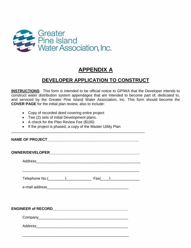
INSTRUCTIONS: This form is intended to be official notice to GPIWA that the Developer intends to construct water distribution system appendages that are intended to become part of, dedicated to, and serviced by the Greater Pine Island Water Association, Inc. This form should become the COVER PAGE for the initial plan review, also to include:
Copy of recorded deed covering entire project
Two (2) sets of initial Development plans.
A check for the Plan Review Fee ($100)
If the project is phased, a copy of the Master Utility Plan ________________________________________________________________ NAME OF PROJECT____________________________________________ OWNER/DEVELOPER___________________________________________
Address__________________________________________________ ________________________________________________________ Telephone No.(________)____________ Fax(____)______________ e-mail address_______________________________________ ENGINEER of RECORD____________________________________ Company___________________________________________
Address____________________________________________ ___________________________________________________
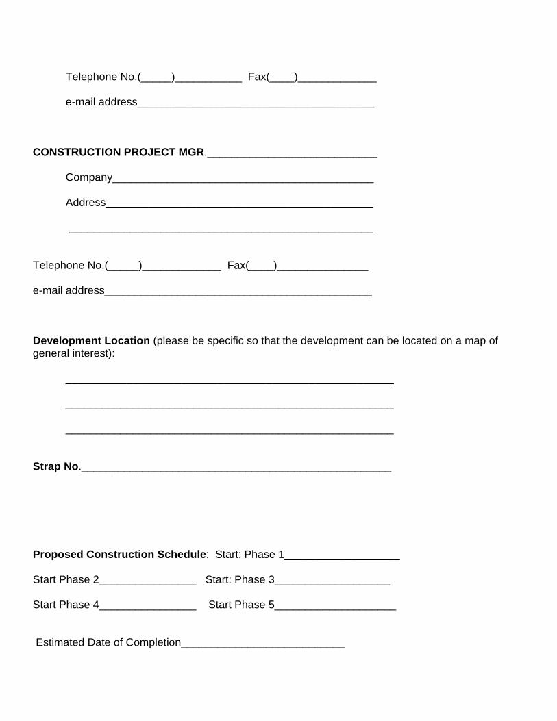
Telephone No.(_____)___________ Fax(____)_____________ e-mail address_______________________________________ CONSTRUCTION PROJECT MGR.____________________________
Company___________________________________________
Address____________________________________________ __________________________________________________ Telephone No.(_____)_____________ Fax(____)_______________ e-mail address____________________________________________ Development Location (please be specific so that the development can be located on a map of general interest): ______________________________________________________ ______________________________________________________ ______________________________________________________ Strap No.___________________________________________________ Proposed Construction Schedule: Start: Phase 1___________________ Start Phase 2________________ Start: Phase 3___________________ Start Phase 4________________ Start Phase 5____________________ Estimated Date of Completion___________________________
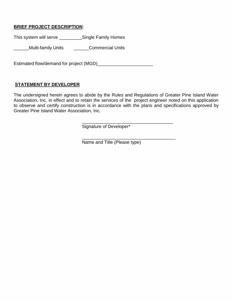
BRIEF PROJECT DESCRIPTION: This system will serve _________Single Family Homes ______Multi-family Units ______Commercial Units Estimated flow/demand for project (MGD)______________________ STATEMENT BY DEVELOPER The undersigned herein agrees to abide by the Rules and Regulations of Greater Pine Island Water Association, Inc. in effect and to retain the services of the project engineer noted on this application to observe and certify construction is in accordance with the plans and specifications approved by Greater Pine Island Water Association, Inc. ____________________________________ Signature of Developer*
_____________________________________ Name and Title (Please type)
GREATER PINE ISLAND WATER ASSOCIATION, INC.
Appendix B
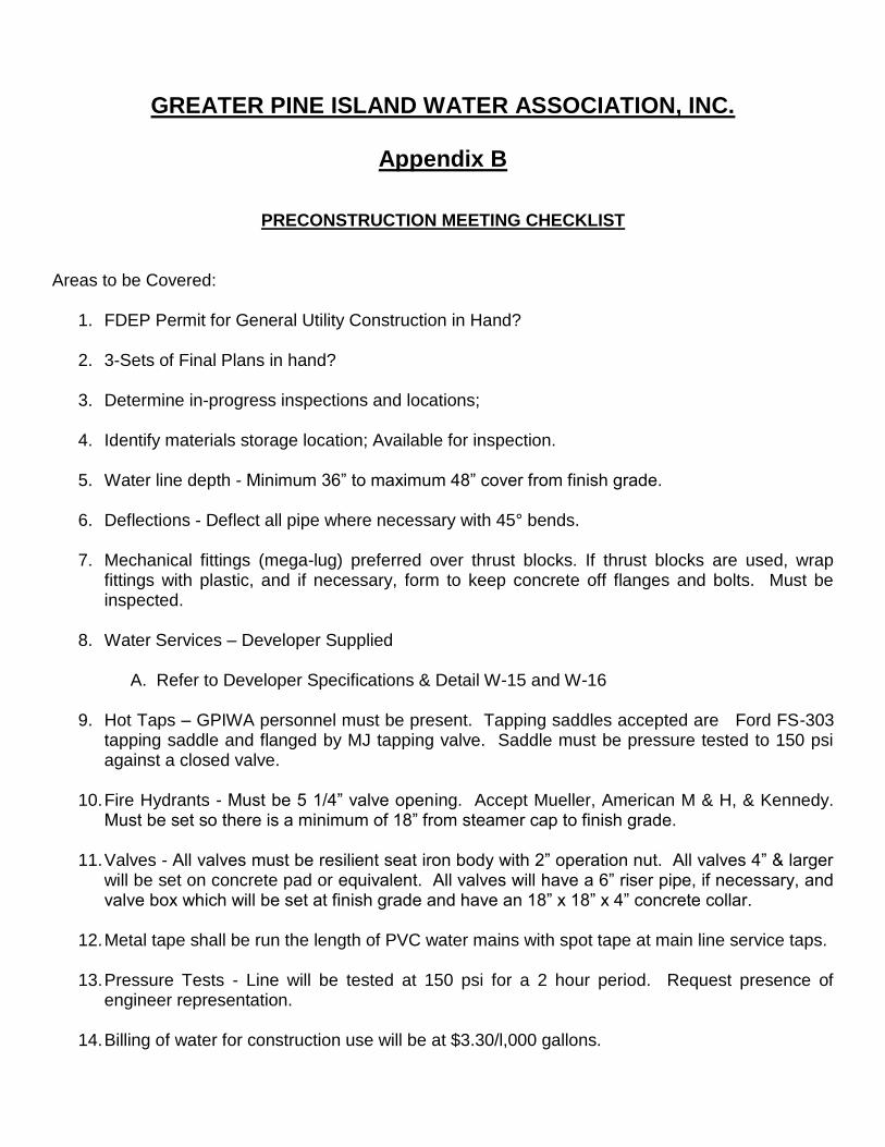
PRECONSTRUCTION MEETING CHECKLIST Areas to be Covered:
1. FDEP Permit for General Utility Construction in Hand? 2. 3-Sets of Final Plans in hand?
3. Determine in-progress inspections and locations;
4. Identify materials storage location; Available for inspection.
5. Water line depth - Minimum 36” to maximum 48” cover from finish grade.
6. Deflections - Deflect all pipe where necessary with 45° bends.
7. Mechanical fittings (mega-lug) preferred over thrust blocks. If thrust blocks are used, wrap
fittings with plastic, and if necessary, form to keep concrete off flanges and bolts. Must be inspected.
8. Water Services – Developer Supplied
A. Refer to Developer Specifications & Detail W-15 and W-16
9. Hot Taps – GPIWA personnel must be present. Tapping saddles accepted are Ford FS-303
tapping saddle and flanged by MJ tapping valve. Saddle must be pressure tested to 150 psi against a closed valve.
10. Fire Hydrants - Must be 5 1/4” valve opening. Accept Mueller, American M & H, & Kennedy.
Must be set so there is a minimum of 18” from steamer cap to finish grade.
11. Valves - All valves must be resilient seat iron body with 2” operation nut. All valves 4” & larger will be set on concrete pad or equivalent. All valves will have a 6” riser pipe, if necessary, and valve box which will be set at finish grade and have an 18” x 18” x 4” concrete collar.
12. Metal tape shall be run the length of PVC water mains with spot tape at main line service taps.
13. Pressure Tests - Line will be tested at 150 psi for a 2 hour period. Request presence of
engineer representation.
14. Billing of water for construction use will be at $3.30/l,000 gallons.
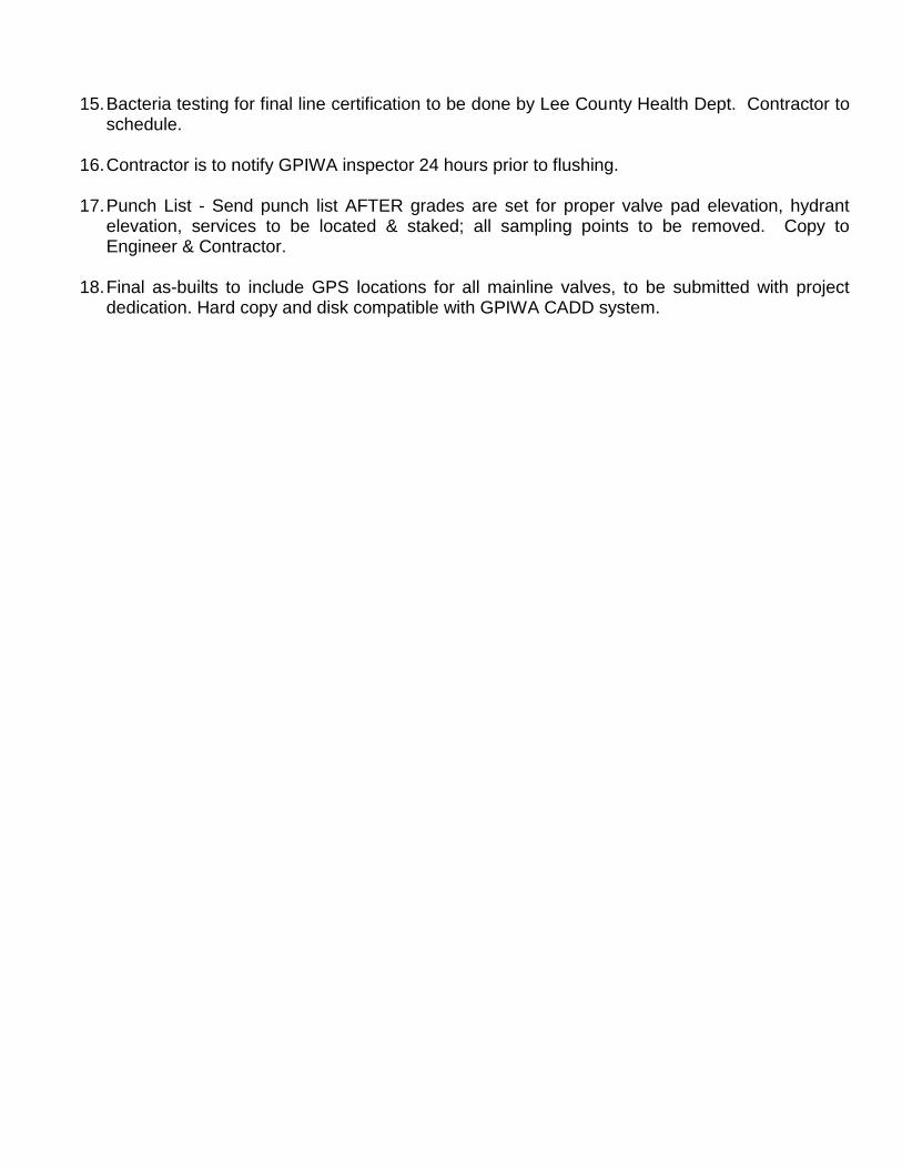
15. Bacteria testing for final line certification to be done by Lee County Health Dept. Contractor to schedule.
16. Contractor is to notify GPIWA inspector 24 hours prior to flushing.
17. Punch List - Send punch list AFTER grades are set for proper valve pad elevation, hydrant
elevation, services to be located & staked; all sampling points to be removed. Copy to Engineer & Contractor.
18. Final as-builts to include GPS locations for all mainline valves, to be submitted with project
dedication. Hard copy and disk compatible with GPIWA CADD system.
GREATER PINE ISLAND WATER ASSOCATION, INC.
Appendix C
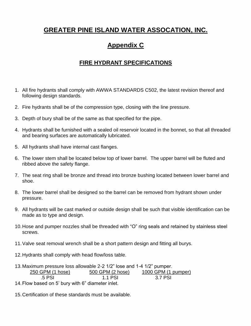
FIRE HYDRANT SPECIFICATIONS
1. All fire hydrants shall comply with AWWA STANDARDS C502, the latest revision thereof and following design standards.
2. Fire hydrants shall be of the compression type, closing with the line pressure. 3. Depth of bury shall be of the same as that specified for the pipe. 4. Hydrants shall be furnished with a sealed oil reservoir located in the bonnet, so that all threaded
and bearing surfaces are automatically lubricated. 5. All hydrants shall have internal cast flanges. 6. The lower stem shall be located below top of lower barrel. The upper barrel will be fluted and
ribbed above the safety flange. 7. The seat ring shall be bronze and thread into bronze bushing located between lower barrel and
shoe. 8. The lower barrel shall be designed so the barrel can be removed from hydrant shown under
pressure. 9. All hydrants will be cast marked or outside design shall be such that visible identification can be
made as to type and design. 10. Hose and pumper nozzles shall be threaded with “O” ring seals and retained by stainless steel
screws. 11. Valve seat removal wrench shall be a short pattern design and fitting all burys. 12. Hydrants shall comply with head flow/loss table. 13. Maximum pressure loss allowable 2-2 1/2” lose and 1-4 1/2” pumper. 250 GPM (1 hose) 500 GPM (2 hose) 1000 GPM (1 pumper) .5 PSI 1.1 PSI 3.7 PSI 14. Flow based on 5’ bury with 6” diameter inlet. 15. Certification of these standards must be available.

16. Mueller A423, American B-62B, American B-84B, Kennedy K81A - Zirk fitting stainless steel and
Dresser M and H style, or approved equal by Matlacha-Pine Island Fire Control District as authority having jurisdiction.
17. Approved hydrants shall have 5 1/4” main valves.
18. Hydrants are to be covered from the time of installation until the jumper assembly is removed and hydrant can be placed into service. No hydrant will be turned on until bacteriological tests are satisfied.

Greater Pine Island Water Association, Inc.
Appendix D
PROCEDURE FOR DEDICATION OF WATER LINES APPROVAL FOR WATER SERVICE
PROJECT ENGINEER
Submittal Package 1. Cover letter a. Requesting approval for service
b. Listing all items submitted
2. FDEP Application to Approve for Service (Copy)
3.FDEP letter certifying construction completion - Permission to place water facilities in service. 4. Bill of Sale (Including Exhibits A & B)
3. Affidavit of No Liens (Including Exhibit A) 4. One (1) year warranty from Developer (Including Exhibit A) 5. Material/cost breakdown from Contractor 6. Certification by Engineer of pipe quantities installed. 7 Engineer’s certification of pressure test 8. Copies of bacteriological analysis 9. Easements a. Recordable Easements b. Certification by Engineer that all improvements being dedicated are located within: (1) Dedicated County Right-of-way or (2) within recorded utility easements on plat. (NOTE: copy of plat to be submitted.) c. Strap Numbers required for recording in Lee County. 10. Two (2) sets of as-built drawings signed and sealed by Engineer. Multi-phased projects should include an updated Master Utility Plan incorporating the added infrastructure.
As-Builts to include GPS locations for mainline isolation valves and fire hydrants. 11. One (1) electronic disk of CADD drawing of as-builts.

GREATER PINE ISLAND WATER ASSOCIATION, INC.
Appendix E
BILL OF SALE
KNOW ALL MEN BY THESE PRESENTS that ________________________________a ____________ corporation authorized to do business in the State of Florida, of the first part, for and in consideration of the sum of Ten Dollars, in lawful money (and other good and valuable considerations) to it paid by Greater Pine Island Water Association, Inc. , of the County of Lee, and the State of Florida, of the second part, the receipt of which is hereby acknowledged by it, has granted, bargained, sold, transferred, set over and delivered, and by these presents does grant, bargain, sell, transfer, set over and deliver unto the party of the second part, its successors and assigns, all those certain goods and chattels, described as follows:
All main and lateral water lines and all appurtenant fixtures and incidentals (collectively referred to as “the components”) on said real property described on the attached Exhibit A (legal description) along with all contractual guarantees relating to the components which are attached hereto as composite Exhibit B (cost-material breakdown). Party of the first part hereby guarantees to party of the second part against defects and workmanship and materials in the components for a period of one (1) year from the date hereof.
TO HAVE AND TO HOLD the same unto the party of the second part, its successors and assigns forever. And the party of the first part, for itself and its successors, hereby covenants to and with the party of the second part, its successors and assigns that it is the lawful owner of the said goods and chattels; and is in full possession of same; that it has good right to sell the same as aforesaid, and that it will warrant and defend the same against the lawful claims and demands of all persons whomsoever. IN WITNESS WHEREOF, the party of the first part has caused its corporate name to be hereunto subscribed and its corporate seal to be affixed by its officer hereunto duly authorized, this the ________ day of ________________, A.D. 20_____. ________________________________ ________________________________ (Signature) (Print or type name and title) CORPORATE SEAL

Bill of Sale Appendix E Page 2 Signed, sealed and delivered in our presence: WITNESSES: ________________________________ ________________________________ (Signature) (Print or type name of witness) ________________________________ ________________________________ (Signature) (Print or type name of witness) STATE OF FLORIDA COUNTY OF LEE The foregoing instrument was acknowledged before me this _____________________ (date) by _____________________________________ of _______________________________________ (name & title of officer or agent) (Name of corporation) on behalf of the corporation. He/she is personally known to me or has produced ________________________ as identification and did (did not) take an oath. (type of identification) ____________________________ (Notary Public) SEAL
GREATER PINE ISLAND WATER ASSOCIATION, INC.
Appendix F
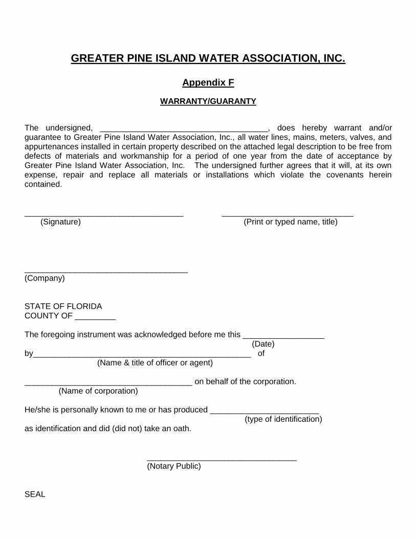
WARRANTY/GUARANTY
The undersigned, _____________________________________, does hereby warrant and/or guarantee to Greater Pine Island Water Association, Inc., all water lines, mains, meters, valves, and appurtenances installed in certain property described on the attached legal description to be free from defects of materials and workmanship for a period of one year from the date of acceptance by Greater Pine Island Water Association, Inc. The undersigned further agrees that it will, at its own expense, repair and replace all materials or installations which violate the covenants herein contained. ___________________________________ _____________________________ (Signature) (Print or typed name, title) ____________________________________ (Company) STATE OF FLORIDA COUNTY OF _________ The foregoing instrument was acknowledged before me this __________________ (Date) by________________________________________________ of (Name & title of officer or agent) _____________________________________ on behalf of the corporation. (Name of corporation) He/she is personally known to me or has produced ________________________ (type of identification) as identification and did (did not) take an oath. _________________________________ (Notary Public) SEAL
GREATER PINE ISLAND WATER ASSOCIATION, INC.
Appendix G
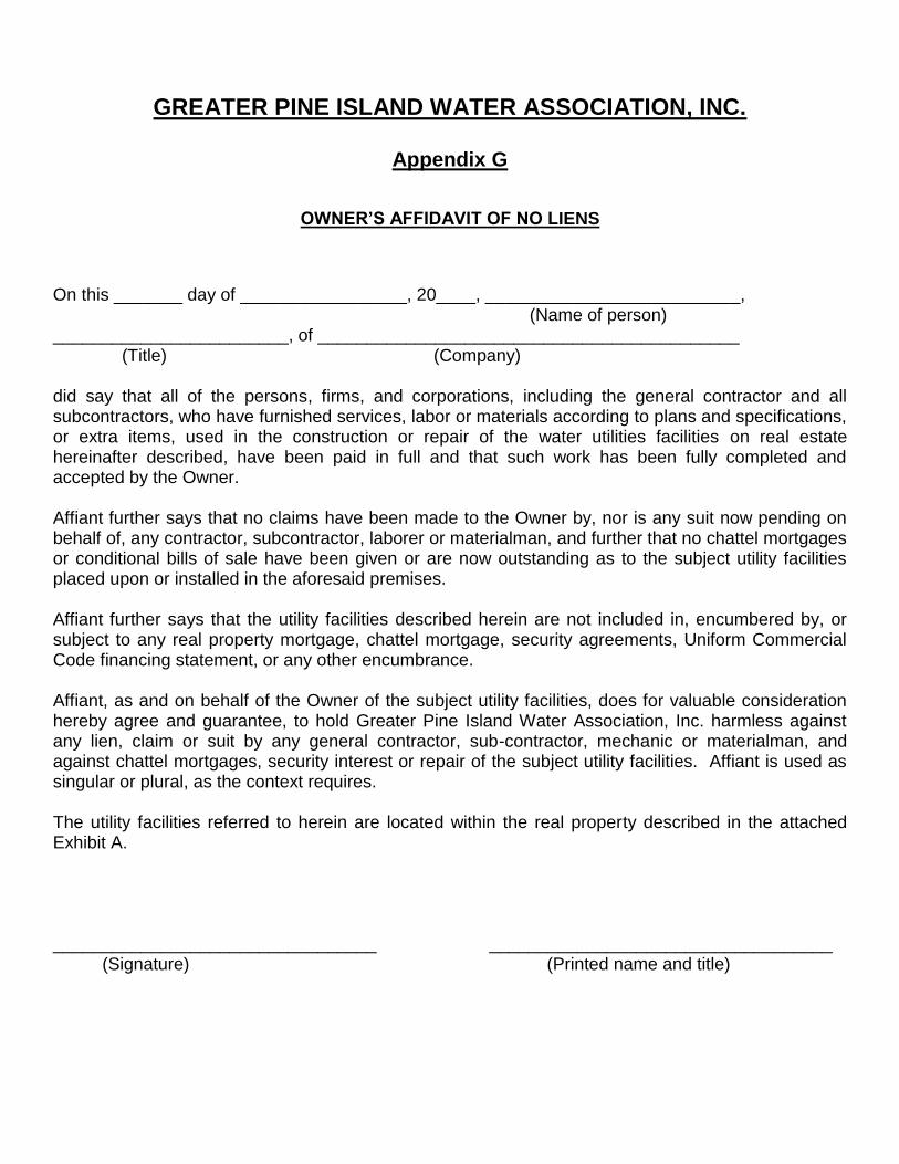
OWNER’S AFFIDAVIT OF NO LIENS
On this _______ day of _________________, 20____, __________________________, (Name of person) ________________________, of ___________________________________________ (Title) (Company) did say that all of the persons, firms, and corporations, including the general contractor and all subcontractors, who have furnished services, labor or materials according to plans and specifications, or extra items, used in the construction or repair of the water utilities facilities on real estate hereinafter described, have been paid in full and that such work has been fully completed and accepted by the Owner. Affiant further says that no claims have been made to the Owner by, nor is any suit now pending on behalf of, any contractor, subcontractor, laborer or materialman, and further that no chattel mortgages or conditional bills of sale have been given or are now outstanding as to the subject utility facilities placed upon or installed in the aforesaid premises. Affiant further says that the utility facilities described herein are not included in, encumbered by, or subject to any real property mortgage, chattel mortgage, security agreements, Uniform Commercial Code financing statement, or any other encumbrance. Affiant, as and on behalf of the Owner of the subject utility facilities, does for valuable consideration hereby agree and guarantee, to hold Greater Pine Island Water Association, Inc. harmless against any lien, claim or suit by any general contractor, sub-contractor, mechanic or materialman, and against chattel mortgages, security interest or repair of the subject utility facilities. Affiant is used as singular or plural, as the context requires. The utility facilities referred to herein are located within the real property described in the attached Exhibit A. _________________________________ ___________________________________ (Signature) (Printed name and title)
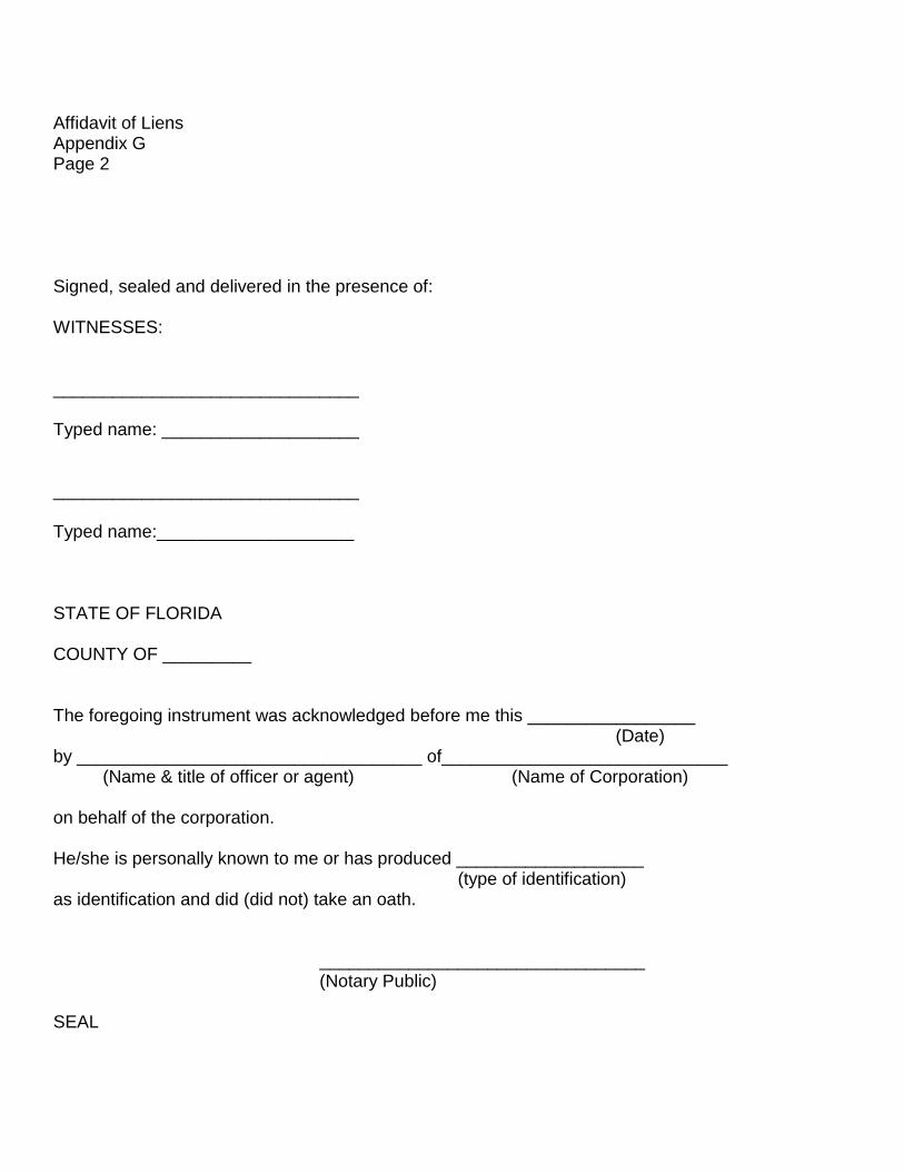
Affidavit of Liens Appendix G Page 2 Signed, sealed and delivered in the presence of: WITNESSES: _______________________________ Typed name: ____________________ _______________________________ Typed name:____________________ STATE OF FLORIDA COUNTY OF _________ The foregoing instrument was acknowledged before me this _________________ (Date) by ___________________________________ of_____________________________ (Name & title of officer or agent) (Name of Corporation) on behalf of the corporation. He/she is personally known to me or has produced ___________________ (type of identification) as identification and did (did not) take an oath. _________________________________ (Notary Public) SEAL
GREATER PINE ISLAND WATER ASSOCIATION, INC.
Appendix H
GRANT OF UTILITY EASEMENT It is hereby agreed that ___________________________________, hereinafter referred to as the “Grantor”, in consideration for TEN ($10.00) DOLLARS and other good and valuable considerations, receipt of which is hereby acknowledged, do hereby grant, sell, transfer, convey and deliver unto the Greater Pine Island Water Association, Inc. , a Florida, Not-For-Profit Corporation, hereinafter referred to as the “Grantee”, and to its successors and assigns, a non-exclusive perpetual easement and right-of-way upon, over, across or below the surface of the following described lands of the Grantor, situated in Lee County, Florida; more particularly described as follows: See Exhibit A (legal description including strap number) and Exhibit B (sketch to accompany legal description) attached hereto and made a part hereof, for the purposes of construction, operation, maintenance, improving or replacing of one or more water, sewer and/or other utility transmission or distribution lines, and all normal appurtenances thereto, including the necessary rights of ingress and egress shall be exercised in a reasonable manner in accordance with the standard practices in the industry, together with the right and privilege to inspect, alter, remove, or relocate such lines, facilities and appurtenances thereto within the easement herein granted, with all rights and privileges necessary or convenient for the full use and enjoyment thereof for the above stated purposes. The Grantor, however, reserves the right and privilege to use the above described lands for any and all other purposes except as would interfere with the Grantee’s use, occupation or enjoyment thereof. Grantee, to the extent responsibly possible, is required to restore the surface of the land to the same condition as it existed at the time of the grant of this Easement. Grantee shall not unreasonably interfere at any time with the rights of Grantor, its successors and assigns, or any other party requiring access to any of the property over which said easement is granted. The cost of construction, operation, maintenance, repair, improvement and/or replacement of the above described facilities shall be borne by Grantee, its successors and assigns. Executed this ________ day of _______________ 20__. ____________________________________ _________________________________ (Signature) (Printed or typed name and title)
Grant of Utility Easement Appendix H Page 2 Signed, sealed and delivered in the presence of: WITNESSES: _______________________________ Typed name: ____________________ _______________________________ Typed name:____________________
STATE OF FLORIDA COUNTY OF _________ The foregoing instrument was acknowledged before me this _________________ (Date) by ___________________________________ of_____________________________ (Name & title of officer or agent) (Name of Corporation) on behalf of the corporation. He/she is personally known to me or has produced ___________________ (type of identification) as identification and did (did not) take an oath. _________________________________ (Notary Public) SEAL

GREATER PINE ISLAND WATER ASSOCATION, INC.
Appendix I
HYDROSTATIC TEST RESULTS FOR WATER MAIN
Project name_______________________________ Date__________________ Client_____________________________________ Job No.________________ Test By___________________________________Witnessed by_____________ Contractor_________________________________ Foreman________________ Road/Street________________________________ Station_____to Station_____
*Allowable Leakage, L in gallons/hour Length of Pipe Nominal Pipe Square Root of L = S x D P Tested (Ft), S Diameter (In), D Test Pressure, P 133,200 _____________________________________________________________________ _____________________________________________________________________ _____________________________________________________________________ _____________________________________________________________________ _____________________________________________________________________
*As per AWWA C600-82
Test Began At __________________________ Pressure on Gauge ______________ First Hour Gallon Used___________________ Pressure on Gauge ______________ Second Hour Gallon Used________________ Pressure on Gauge ______________ 24 Hour Total Gallon Used_______________ Pressure on Gauge_______________ Results: Passed_________ Failed _________ Remarks: _______________________________________________________________________________________________________________________________________________________________________________________________________________ Inspector’s Signature__________________