line differential protection / 7sd52/53
TRANSCRIPT
Line Differential Protection / 7SD52/53
7/43Siemens SIP · Edition No. 7
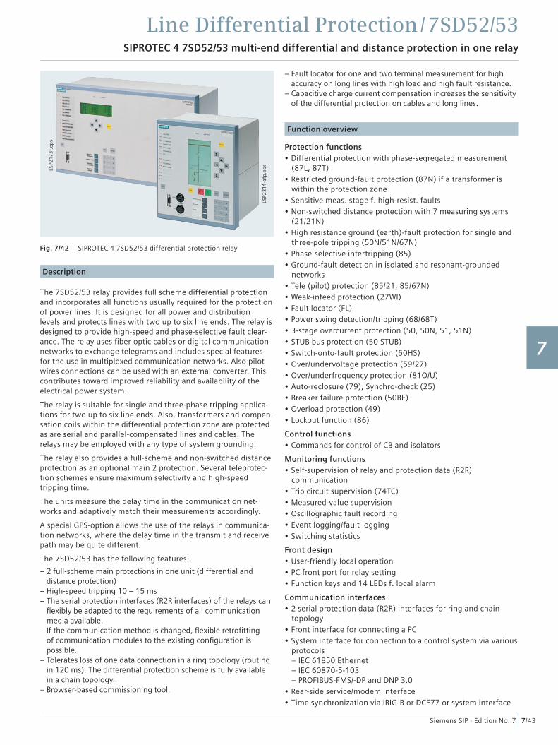
SIPROTEC 4 7SD52/53 multi-end differential and distance protection in one relay
Description
The 7SD52/53 relay provides full scheme differential protection and incorporates all functions usually required for the protection of power lines. It is designed for all power and distribution levels and protects lines with two up to six line ends. The relay is designed to provide high-speed and phase-selective fault clear-ance. The relay uses fi ber-optic cables or digital communication networks to exchange telegrams and includes special features for the use in multiplexed communication networks. Also pilot wires connections can be used with an external converter. This contributes toward improved reliability and availability of the electrical power system.
The relay is suitable for single and three-phase tripping applica-tions for two up to six line ends. Also, transformers and compen-sation coils within the differential protection zone are protected as are serial and parallel-compensated lines and cables. The relays may be employed with any type of system grounding.
The relay also provides a full-scheme and non-switched distance protection as an optional main 2 protection. Several teleprotec-tion schemes ensure maximum selectivity and high-speed tripping time.
The units measure the delay time in the communication net-works and adaptively match their measurements accordingly.
A special GPS-option allows the use of the relays in communica-tion networks, where the delay time in the transmit and receive path may be quite different.
The 7SD52/53 has the following features:
– 2 full-scheme main protections in one unit (differential and distance protection)
– High-speed tripping 10 – 15 ms– The serial protection interfaces (R2R interfaces) of the relays can
fl exibly be adapted to the requirements of all communication media available.
– If the communication method is changed, fl exible retrofi tting of communication modules to the existing confi guration is possible.
– Tolerates loss of one data connection in a ring topology (routing in 120 ms). The differential protection scheme is fully available in a chain topology.
– Browser-based commissioning tool.
– Fault locator for one and two terminal measurement for high accuracy on long lines with high load and high fault resistance.
– Capacitive charge current compensation increases the sensitivity of the differential protection on cables and long lines.
Function overview
Protection functions• Differential protection with phase-segregated measurement
(87L, 87T)• Restricted ground-fault protection (87N) if a transformer is
within the protection zone• Sensitive meas. stage f. high-resist. faults• Non-switched distance protection with 7 measuring systems
(21/21N)• High resistance ground (earth)-fault protection for single and
three-pole tripping (50N/51N/67N)• Phase-selective intertripping (85)• Ground-fault detection in isolated and resonant-grounded
networks• Tele (pilot) protection (85/21, 85/67N)• Weak-infeed protection (27WI)• Fault locator (FL)• Power swing detection/tripping (68/68T)• 3-stage overcurrent protection (50, 50N, 51, 51N)• STUB bus protection (50 STUB)• Switch-onto-fault protection (50HS)• Over/undervoltage protection (59/27)• Over/underfrequency protection (81O/U)• Auto-reclosure (79), Synchro-check (25)• Breaker failure protection (50BF)• Overload protection (49)• Lockout function (86)
Control functions• Commands for control of CB and isolators
Monitoring functions• Self-supervision of relay and protection data (R2R)
communication• Trip circuit supervision (74TC)• Measured-value supervision• Oscillographic fault recording• Event logging/fault logging• Switching statistics
Front design• User-friendly local operation• PC front port for relay setting• Function keys and 14 LEDs f. local alarm
Communication interfaces• 2 serial protection data (R2R) interfaces for ring and chain
topology• Front interface for connecting a PC• System interface for connection to a control system via various
protocols– IEC 61850 Ethernet– IEC 60870-5-103– PROFIBUS-FMS/-DP and DNP 3.0
• Rear-side service/modem interface• Time synchronization via IRIG-B or DCF77 or system interface
Fig. 7/42 SIPROTEC 4 7SD52/53 differential protection relay
LSP2
314
-afp
.ep
s
LSP2
173
f.ep
s
1
2
3
4
5
6
7
8
9
10
11
12
13
14
15
Line Differential Protection / 7SD52/53Application
Application
7/44 Siemens SIP · Edition No. 7
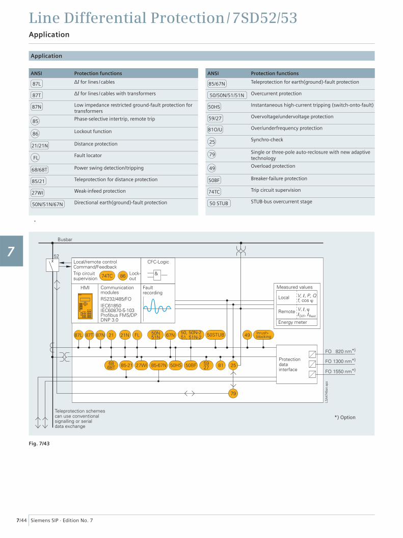
Fig. 7/43
ANSI Protection functions
85/67N Teleprotection for earth(ground)-fault protection
50/50N/51/51N Overcurrent protection
50HS Instantaneous high-current tripping (switch-onto-fault)
59/27 Overvoltage/undervoltage protection
81O/U Over/underfrequency protection
25 Synchro-check
79 Single or three-pole auto-reclosure with new adaptive technology
49 Overload protection
50BF Breaker-failure protection
74TC Trip circuit supervision
50 STUB STUB-bus overcurrent stage
ANSI Protection functions
87L ΔI for lines / cables
87T ΔI for lines / cables with transformers
87N Low impedance restricted ground-fault protection for transformers
85 Phase-selective intertrip, remote trip
86 Lockout function
21/21N Distance protection
FL Fault locator
68/68T Power swing detection/tripping
85/21 Teleprotection for distance protection
27WI Weak-infeed protection
50N/51N/67N Directional earth(ground)-fault protection
*) Option
1
2
3
4
5
6
7
8
9
10
11
12
13
14
15
Line Differential Protection / 7SD52/53
7/45Siemens SIP · Edition No. 7
Application
Typical applications
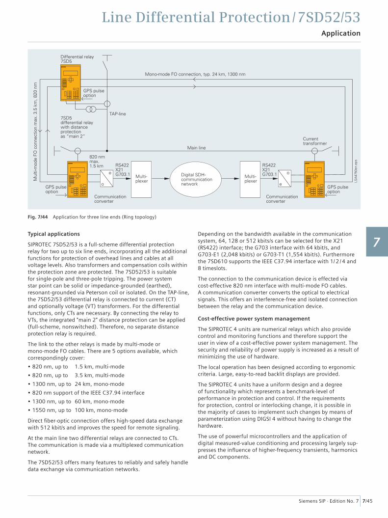
SIPROTEC 7SD52/53 is a full-scheme differential protection relay for two up to six line ends, incorporating all the additional functions for protection of overhead lines and cables at all voltage levels. Also transformers and compensation coils within the protection zone are protected. The 7SD52/53 is suitable for single-pole and three-pole tripping. The power system star point can be solid or impedance-grounded (earthed), resonant-grounded via Peterson coil or isolated. On the TAP-line, the 7SD52/53 differential relay is connected to current (CT) and optionally voltage (VT) transformers. For the differential functions, only CTs are necessary. By connecting the relay to VTs, the integrated "main 2" distance protection can be applied (full-scheme, nonswitched). Therefore, no separate distance protection relay is required.
The link to the other relays is made by multi-mode or mono-mode FO cables. There are 5 options available, which correspondingly cover:
• 820 nm, up to 1.5 km, multi-mode
• 820 nm, up to 3.5 km, multi-mode
• 1300 nm, up to 24 km, mono-mode
• 820 nm support of the IEEE C37.94 interface
• 1300 nm, up to 60 km, mono-mode
• 1550 nm, up to 100 km, mono-mode
Direct fi ber-optic connection offers high-speed data exchange with 512 kbit/s and improves the speed for remote signaling.
At the main line two differential relays are connected to CTs. The communication is made via a multiplexed communication network.
The 7SD52/53 offers many features to reliably and safely handle data exchange via communication networks.
Depending on the bandwidth available in the communication system, 64, 128 or 512 kbits/s can be selected for the X21 (RS422) interface; the G703 interface with 64 kbit/s, and G703-E1 (2,048 kbit/s) or G703-T1 (1,554 kbit/s). Furthermore the 7SD610 supports the IEEE C37.94 interface with 1/ 2 / 4 and 8 timeslots.
The connection to the communication device is effected via cost-effective 820 nm interface with multi-mode FO cables. A communication converter converts the optical to electrical signals. This offers an interference-free and isolated connection between the relay and the communication device.
Cost-effective power system management
The SIPROTEC 4 units are numerical relays which also provide control and monitoring functions and therefore support the user in view of a cost-effective power system management. The security and reliability of power supply is increased as a result of minimizing the use of hardware.
The local operation has been designed according to ergonomic criteria. Large, easy-to-read backlit displays are provided.
The SIPROTEC 4 units have a uniform design and a degree of functionality which represents a benchmark-level of performance in protection and control. If the requirements for protection, control or interlocking change, it is possible in the majority of cases to implement such changes by means of parameterization using DIGSI 4 without having to change the hardware.
The use of powerful microcontrollers and the application of digital measured-value conditioning and processing largely sup-presses the infl uence of higher-frequency transients, harmonics and DC components.
Fig. 7/44 Application for three line ends (Ring topology)
1
2
3
4
5
6
7
8
9
10
11
12
13
14
15
Line Differential Protection / 7SD52/53Construction
7/46 Siemens SIP · Edition No. 7
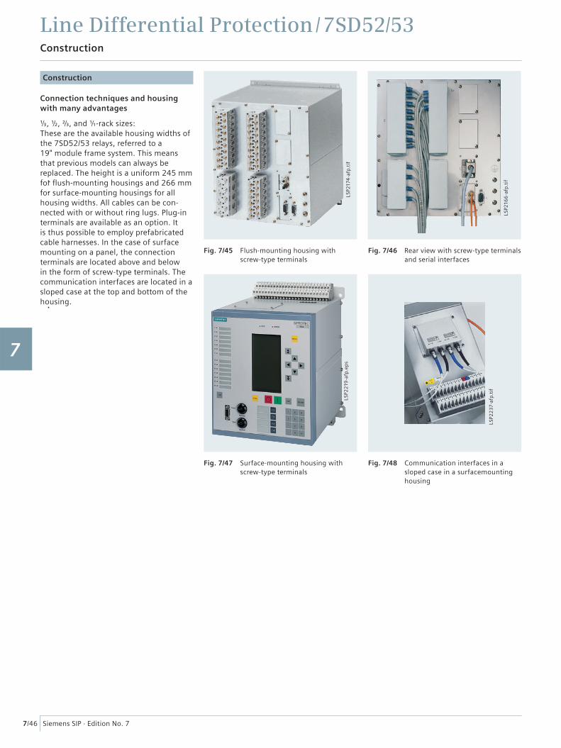
Fig. 7/45 Flush-mounting housing with screw-type terminals
Fig. 7/46 Rear view with screw-type terminals and serial interfaces
Fig. 7/47 Surface-mounting housing with screw-type terminals
Fig. 7/48 Communication interfaces in a sloped case in a surfacemounting housing
LSP2
166
-afp
.tif
LSP2
174
-afp
.tif
LSP2
219
-afp
.ep
s
LSP2
23
7-af
p.ti
f
Construction
Connection techniques and housing with many advantages
⅓, ½, ²⁄₃, and �-rack sizes: These are the available housing widths of the 7SD52/53 relays, referred to a 19" module frame system. This means that previous models can always be replaced. The height is a uniform 245 mm for fl ush-mounting housings and 266 mm for surface-mounting housings for all housing widths. All cables can be con-nected with or without ring lugs. Plug-in terminals are available as an option. It is thus possible to employ prefabricated cable harnesses. In the case of surface mounting on a panel, the connection terminals are located above and below in the form of screw-type terminals. The communication interfaces are located in a sloped case at the top and bottom of the housing.
1
2
3
4
5
6
7
8
9
10
11
12
13
14
15
Line Differential Protection / 7SD52/53Protection functions
7/47Siemens SIP · Edition No. 7
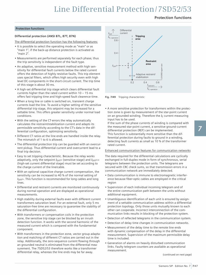
Fig. 7/49 Tripping characteristic
Protection functions
Differential protection (ANSI 87L, 87T, 87N)
The differential protection function has the following features:
• It is possible to select the operating mode as "main" or as "main 1", if the back-up distance protection is activated as "main 2".
• Measurements are performed separately for each phase; thus the trip sensitivity is independent of the fault type.
• An adaptive, sensitive measurement method with high sen-sitivity for differential fault currents below the rated current offers the detection of highly resistive faults. This trip element uses special fi lters, which offers high security even with high level DC-components in the short-circuit current. The trip time of this stage is about 30 ms.
• A high-set differential trip stage which clears differential fault currents higher than the rated current within 10 – 15 ms offers fast tripping time and high-speed fault clearence time.
• When a long line or cable is switched on, transient charge currents load the line. To avoid a higher setting of the sensitive differential trip stage, this setpoint may be increased for a settable time. This offers greater sensitivity under normal load conditions.
• With the setting of the CT-errors the relay automatically calculates the restraint/stabilization current and adapts its permissible sensitivity according to the CT’s data in the dif-ferential confi guration, optimizing sensitivity.
• Different CT ratios at the line ends are handled inside the relay. The mismatch of 1 to 6 is allowed.
• The differential protection trip can be guarded with an overcur-rent pickup. Thus differential current and overcurrent lead to a fi nal trip decision.
• Easy to set tripping characteristic. Because the relay works adaptively, only the setpoint IDiff> (sensitive stage) and IDiff>> (high-set current differential stage) must be set according to the charge current of the line/cable.
• With an optional capacitive charge current compensation, the sensitivity can be increased to 40 % of the normal setting of IDiff>. This function is recommended for long cables and long lines.
• Differential and restraint currents are monitored continuously during normal operation and are displayed as operational measurements.
• High stability during external faults even with different current transformers saturation level. For an external fault, only 5 ms saturation-free time are necessary to guarantee the stability of the differential confi guration.
• With transformers or compensation coils in the protection zone, the sensitive trip stage can be blocked by an inrush detection function. It works with the second harmonic of the measured current which is compared with the fundamental component.
• With transformers in the protection zone, vector group adapta-tion and matching of different CT ratios are carried out in the relay. Additionally, the zero-sequence current fl owing through an grounded neutral is eliminated from the differential mea-surement. The 7SD52/53 therefore works like a transformer differential relay, whereas the line ends may be far away.
• A more sensitive protection for transformers within the protec-tion zone is given by measurement of the star-point current on an grounded winding. Therefore the IE current measuring input has to be used.If the sum of the phase currents of winding is compared with the measured star-point current, a sensitive ground-current differential protection (REF) can be implemented.This function is substantially more sensitive than the dif-ferential protection during faults to ground in a winding, detecting fault currents as small as 10 % of the transformer rated current.
Enhanced communication features for communication networks
The data required for the differential calculations are cyclically exchanged in full-duplex mode in form of synchronous, serial telegrams between the protection units. The telegrams are secured with CRC check sums, so that transmission errors in a communication network are immediately detected.
• Data communication is immune to electromagnetic interfer-ence because fi ber-optic cables are employed in the critical region
• Supervision of each individual incoming telegram and of the entire communication path between the units without additional equipment.
• Unambiguous identifi cation of each unit is ensured by assign-ment of a settable communication address within a differential protection topology. Only those units mutually known to each other can cooperate. Incorrect interconnection of the com-munication links results in blocking of the protection system.
• Detection of refl ected telegrams in the communication system.
• Detection of delay time changes in communication networks.
• Measurement of the delay time to the remote line ends with dynamic compensation of the delay in the differential measurement. Supervision of the maximum permissible delay time is included.
• Generation of alarms on heavily disturbed communication links. Faulty telegram counters are available as operational measurement.
(continued on next page)
1
2
3
4
5
6
7
8
9
10
11
12
13
14
15
Line Differential Protection / 7SD52/53Protection functions
7/48 Siemens SIP · Edition No. 7
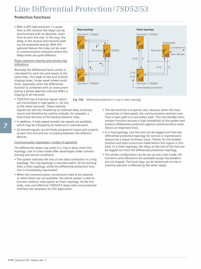
Fig. 7/50 Differential protection in ring or chain topology
• With a GPS high-precision 1-s pulse from a GPS receiver the relays can be synchronized with an absolute, exact time at each line end. In this way, the delay in the receive and transmit path can be measured exactly. With this optional feature the relay can be used in communication networks where this delay times are quite different.
Phase-selective intertrip and remote trip/indications
Normally the differential fault current is calculated for each line end nearly at the same time. This leads to fast and uniform tripping times. Under weak infeed condi-tions, especially when the differential function is combined with an overcurrent pickup a phase-selective intertrip offers a tripping of all line ends.
• 7SD52/53 has 4 intertrip signals which are transmitted in high-speed (< 20 ms) to the other line ends. These intertrip signals can also be initiated by an external relay via binary inputs and therefore be used to indicate, for example, a directional decision of the backup distance relay.
• In addition, 4 high-speed remote trip signals are available, which may be initiated by an external or internal event.
• 24 remote signals can be freely assigned to inputs and outputs at each line end and are circulating between the different devices.
Communication topologies / modes of operation
The differential relays may work in a ring or daisy chain line topology. Use of a test mode offer advantages under commis-sioning and service conditions.
• The system tolerates the loss of one data connection in a ring topology. The ring topology is rerouted within 20 ms forming then a chain topology, while the differential protection func-tion is immediately reactivated.
• When the communication connections need to be reduced or when these are not available, the whole system is able to function without interruption as chain topology. At the line ends, only cost-effective 7SD52/53 relays with one protection interface are necessary for this application.
• The two-end line is a special case, because when the main connection is interrupted, the communication switches over from a main path to a secondary path. This hot standby trans-mission function ensures a high availability of the system and protects differential protection against communication route failure on important lines.
• In a ring topology, one line end can be logged out from the differential protection topology for service or maintenance reasons by a signal via binary input. Checks for the breaker position and load current are made before this logout is initi-ated. In a chain topology, the relays at the end of the line can be logged out from the differential protection topology.
• The whole confi guration can be set up into a test mode. All functions and indications are available except the breakers are not tripped. The local relay can be tested and no trip or intertrip reaction is effected by the other relays.
1
2
3
4
5
6
7
8
9
10
11
12
13
14
15
Line Differential Protection / 7SD52/53Protection functions
7/49Siemens SIP · Edition No. 7
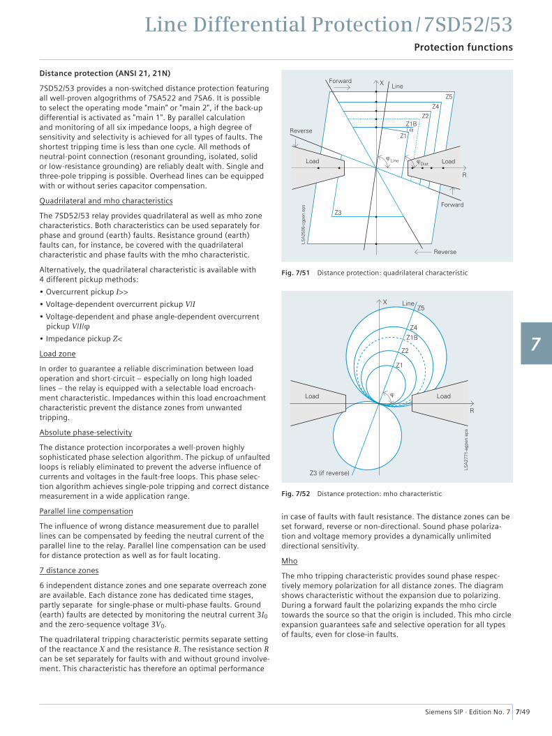
Fig. 7/51 Distance protection: quadrilateral characteristic
Fig. 7/52 Distance protection: mho characteristic
Distance protection (ANSI 21, 21N)
7SD52/53 provides a non-switched distance protection featuring all well-proven algogrithms of 7SA522 and 7SA6. It is possible to select the operating mode "main" or "main 2", if the back-up differential is activated as "main 1". By parallel calculation and monitoring of all six impedance loops, a high degree of sensitivity and selectivity is achieved for all types of faults. The shortest tripping time is less than one cycle. All methods of neutral-point connection (resonant grounding, isolated, solid or low-resistance grounding) are reliably dealt with. Single and three-pole tripping is possible. Overhead lines can be equipped with or without series capacitor compensation.
Quadrilateral and mho characteristics
The 7SD52/53 relay provides quadrilateral as well as mho zone characteristics. Both characteristics can be used separately for phase and ground (earth) faults. Resistance ground (earth) faults can, for instance, be covered with the quadrilateral characteristic and phase faults with the mho characteristic.
Alternatively, the quadrilateral characteristic is available with 4 different pickup methods:
• Overcurrent pickup I>>
• Voltage-dependent overcurrent pickup V/I
• Voltage-dependent and phase angle-dependent overcurrent pickup V/I/φ
• Impedance pickup Z<
Load zone
In order to guarantee a reliable discrimination between load operation and short-circuit – especially on long high loaded lines – the relay is equipped with a selectable load encroach-ment characteristic. Impedances within this load encroachment characteristic prevent the distance zones from unwanted tripping.
Absolute phase-selectivity
The distance protection incorporates a well-proven highly sophisticated phase selection algorithm. The pickup of unfaulted loops is reliably eliminated to prevent the adverse infl uence of currents and voltages in the fault-free loops. This phase selec-tion algorithm achieves single-pole tripping and correct distance measurement in a wide application range.
Parallel line compensation
The infl uence of wrong distance measurement due to parallel lines can be compensated by feeding the neutral current of the parallel line to the relay. Parallel line compensation can be used for distance protection as well as for fault locating.
7 distance zones
6 independent distance zones and one separate overreach zone are available. Each distance zone has dedicated time stages, partly separate for single-phase or multi-phase faults. Ground (earth) faults are detected by monitoring the neutral current 3I0
and the zero-sequence voltage 3V0.
The quadrilateral tripping characteristic permits separate setting of the reactance X and the resistance R. The resistance section R can be set separately for faults with and without ground involve-ment. This characteristic has therefore an optimal performance
in case of faults with fault resistance. The distance zones can be set forward, reverse or non-directional. Sound phase polariza-tion and voltage memory provides a dynamically unlimited directional sensitivity.
Mho
The mho tripping characteristic provides sound phase respec-tively memory polarization for all distance zones. The diagram shows characteristic without the expansion due to polarizing. During a forward fault the polarizing expands the mho circle towards the source so that the origin is included. This mho circle expansion guarantees safe and selective operation for all types of faults, even for close-in faults.
1
2
3
4
5
6
7
8
9
10
11
12
13
14
15
Line Differential Protection / 7SD52/53Protection functions
7/50 Siemens SIP · Edition No. 7
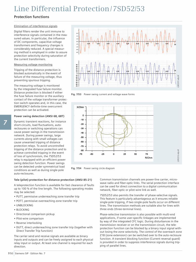
Fig. 7/53 Power swing current and voltage wave forms
Fig. 7/54 Power swing circle diagram
Elimination of interference signals
Digital fi lters render the unit immune to interference signals contained in the mea-sured values. In particular, the infl uence of DC components, capacitive voltage transformers and frequency changes is considerably reduced. A special measur-ing method is employed in order to assure protection selectivity during saturation of the current transformers.
Measuring voltage monitoring
Tripping of the distance protection is blocked automatically in the event of failure of the measuring voltage, thus preventing spurious tripping.
The measuring voltage is monitored by the integrated fuse failure monitor. Distance protection is blocked if either the fuse failure monitor or the auxiliary contact of the voltage transformer protec-tion switch operates and, in this case, the EMERGENCY defi nite-time overcurrent protection can be activated.
Power swing detection (ANSI 68, 68T)
Dynamic transient reactions, for instance short-circuits, load fl uctuations, auto-reclosures or switching operations can cause power swings in the transmission network. During power swings, large currents along with small voltages can cause unwanted tripping of distance protection relays. To avoid uncontrolled tripping of the distance protection and to achieve controlled tripping in the event of loss of synchronism, the 7SD52/53 relay is equipped with an effi cient power swing detection function. Power swings can be detected under symmetrical load conditions as well as during single-pole auto-reclosures.
Tele (pilot) protection for distance protection (ANSI 85-21)
A teleprotection function is available for fast clearance of faults up to 100 % of the line length. The following operating modes may be selected:
• PUTT, permissive underreaching zone transfer trip
• POTT, permissive overreaching zone transfer trip
• UNBLOCKING
• BLOCKING
• Directional comparison pickup
• Pilot-wire comparison
• Reverse interlocking
• DUTT, direct underreaching zone transfer trip (together with Direct Transfer Trip function)
The carrier send and receive signals are available as binary inputs and outputs and can be freely assigned to each physical relay input or output. At least one channel is required for each direction.
Common transmission channels are power-line carrier, micro-wave radio and fi ber-optic links. The serial protection interface can be used for direct connection to a digital communication network, fi ber-optic or pilot-wire link as well.
7SD52/53 also permits the transfer of phase-selective signals. This feature is particularly advantageous as it ensures reliable single-pole tripping, if two single-pole faults occur on different lines. The transmission methods are suitable also for lines with three ends (three-terminal lines).
Phase-selective transmission is also possible with multi-end applications, if some user-specifi c linkages are implemented by way of the integrated CFC logic. During disturbances in the transmission receiver or on the transmission circuit, the tele- protection function can be blocked by a binary input signal with-out losing the zone selectivity. The control of the overreach zone Z1B (zone extension) can be switched over to the auto-reclosure function. A transient blocking function (Current reversal guard) is provided in order to suppress interference signals during trip-ping of parallel lines.
LSP2
311-
afp.
tif
LSP2
312
-afp
.tif
1
2
3
4
5
6
7
8
9
10
11
12
13
14
15
Line Differential Protection / 7SD52/53Protection functions
7/51Siemens SIP · Edition No. 7
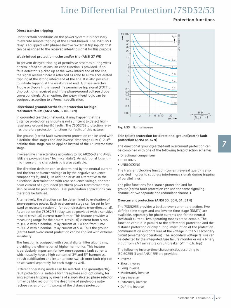
Fig. 7/55 Normal inverse
Direct transfer tripping
Under certain conditions on the power system it is necessary to execute remote tripping of the circuit-breaker. The 7SD52/53 relay is equipped with phase-selective “external trip inputs” that can be assigned to the received inter-trip signal for this purpose.
Weak-infeed protection: echo and/or trip (ANSI 27 WI)
To prevent delayed tripping of permissive schemes during weak or zero infeed situations, an echo function is provided. If no fault detector is picked up at the weak-infeed end of the line, the signal received here is returned as echo to allow accelerated tripping at the strong infeed end of the line. It is also possible to initiate tripping at the weak-infeed end. A phase-selective 1-pole or 3-pole trip is issued if a permissive trip signal (POTT or Unblocking) is received and if the phase-ground voltage drops correspondingly. As an option, the weak-infeed logic can be equipped according to a French specifi cation.
Directional ground(earth)-fault protection for high-resistance faults (ANSI 50N, 51N, 67N)
In grounded (earthed) networks, it may happen that the distance protection sensitivity is not suffi cient to detect high-resistance ground (earth) faults. The 7SD52/53 protection relay has therefore protection functions for faults of this nature.
The ground (earth)-fault overcurrent protection can be used with 3 defi nite-time stages and one inverse-time stage (IDMT). A 4th defi nite-time stage can be applied instead of the 1st inverse-time stage.
Inverse-time characteristics according to IEC 60255-3 and ANSI/IEEE are provided (see “Technical data”). An additional logarith-mic inverse-time characteristic is also available.
The direction decision can be determined by the neutral current and the zero-sequence voltage or by the negative-sequence components V2 and I2. In addition or as an alternative to the directional determination with zero-sequence voltage, the star-point current of a grounded (earthed) power transformer may also be used for polarization. Dual polarization applications can therefore be fulfi lled.
Alternatively, the direction can be determined by evaluation of zero-sequence power. Each overcurrent stage can be set in for-ward or reverse direction or for both directions (non-directional). As an option the 7SD52/53 relay can be provided with a sensitive neutral (residual) current transformer. This feature provides a measuring range for the neutral (residual) current from 5 mA to 100 A with a nominal relay current of 1 A and from 5 mA to 500 A with a nominal relay current of 5 A. Thus the ground (earth)-fault overcurrent protection can be applied with extreme sensitivity.
The function is equipped with special digital fi lter algorithms, providing the elimination of higher harmonics. This feature is particularly important for low zero-sequence fault currents which usually have a high content of 3rd and 5th harmonics. Inrush stabilization and instantaneous switch-onto-fault trip can be activated separately for each stage as well.
Different operating modes can be selected. The ground(earth)-fault protection is suitable for three-phase and, optionally, for single-phase tripping by means of a sophisticated phase selector. It may be blocked during the dead time of single-pole auto- reclose cycles or during pickup of the distance protection.
Tele (pilot) protection for directional ground(earth)-fault protection (ANSI 85-67N)
The directional ground(earth)-fault overcurrent protection can be combined with one of the following teleprotection schemes:
• Directional comparison• BLOCKING• UNBLOCKING
The transient blocking function (current reversal guard) is also provided in order to suppress interference signals during tripping of parallel lines.
The pilot functions for distance protection and for ground(earth)-fault protection can use the same signaling channel or two separate and redundant channels.
Overcurrent protection (ANSI 50, 50N, 51, 51N)
The 7SD52/53 provides a backup over-current protection. Two defi nite-time stages and one inverse-time stage (IDMTL) are available, separately for phase currents and for the neutral (residual) current. Two operating modes are selectable. The function can run in parallel to the differential protection and the distance protection or only during interruption of the protection communication and/or failure of the voltage in the VT secondary circuit (emergency operation). The secondary voltage failure can be detected by the integrated fuse failure monitor or via a binary input from a VT miniature circuit-breaker (VT m.c.b. trip).
The following inverse-time characteristics according to IEC 60255-3 and ANSI/IEEE are provided:
• Inverse• Short inverse• Long inverse• Moderately inverse• Very inverse• Extremely inverse• Defi nite inverse
t =0,14
I / Ip( )0,02
−1Tp
1
2
3
4
5
6
7
8
9
10
11
12
13
14
15
Line Differential Protection / 7SD52/53Protection functions
7/52 Siemens SIP · Edition No. 7
STUB bus overcurrent protection (ANSI 50(N)-STUB)
The STUB bus overcurrent protection is a separate defi nite-time overcurrent stage. It can be activated from a binary input signal-ing the line isolator (disconnector) is open. Settings are available for phase and ground (earth)-faults.
Instantaneous high-speed switch-onto-fault overcurrent protection (ANSI 50HS)
Instantaneous tripping is possible when energizing a faulty line. In the event of large fault currents, the high-speed switch-onto-fault overcurrent stage can initiate very fast 3-pole tripping.
With lower fault currents, instantaneous tripping after switch-onto-fault is also possible
– if the breaker positions at the line ends are monitored and connected to the relays. This breaker position monitor offers a high-speed trip during switch-onto-fault conditions.
– with the overreach distance zone Z1B or just with pickup in any zone.
The switch-onto-fault initiation can be detected via the binary input "manual close" or automatically via measurement.
Fault locator
The integrated fault locator calculates the fault impedance and the distance-to-fault. The result is displayed in ohms, miles, kilometers or in percent of the line length. Parallel line and load current compensation is also available.
As an option for a line with two ends, a fault locator function with measurement at both ends of the line is available.Thanks to this feature, accuracy of measurement on long lines under high load conditions and high fault resistances is considerably increased.
Overvoltage protection, undervoltage protection (ANSI 59, 27)
A voltage rise can occur on long lines that are operating at no-load or are only lightly loaded. The 7SD52/53 contains a number of overvoltage measuring elements. Each measuring element is of two-stage design. The following measuring elements are available:
• Phase-to-ground overvoltage• Phase-to-phase overvoltage• Zero-sequence overvoltage
The zero-sequence voltage can be connected to the 4th voltage input or be derived from the phase voltages.
• Positive-sequence overvoltage of the local end or calculated for the remote end of the line (compounding).
• Negative-sequence overvoltage
Tripping by the overvoltage measuring elements can be effected either at the local circuit-breaker or at the remote station by means of a transmitted signal.
The 7SD52/53 is fi tted, in addition, with three two-stage under-voltage measuring elements:
• Phase-to-ground undervoltage• Phase-to-phase undervoltage• Positive-sequence undervoltage
The undervoltage measuring elements can be blocked by means of a minimum current criterion and by means of binary inputs.
Frequency protection (ANSI 81O/U)
Frequency protection can be used for overfrequency and underfrequency protection. Unwanted frequency changes in the network can be detected and the load can be removed at a specifi ed frequency setting. Frequency protection can be used over a wide frequency range (45 to 55, 55 to 65 Hz). There are four elements (selectable as overfrequency or underfrequency) and each element can be delayed separately.
Breaker failure protection (ANSI 50BF)
The 7SD52/53 relay incorporates a two-stage breaker failure protection to detect the failure of tripping command execution, for example due to a defective ciruit-breaker. The current detec-tion logic is phase-segregated and can therefore also be used in single-pole tripping schemes. If the fault current is not inter-rupted after a settable time delay has expired, a retrip command or a busbar trip command is generated. The breaker failure protection can be initiated by all integrated protection functions as well as by external devices via binary input signals.
Auto-reclosure (ANSI 79)
The 7SD52/53 relay is equipped with an auto-reclose function (AR). The function includes several operating modes:
• 3-pole auto-reclosure for all types of faults; different dead times are available depending the type of fault
• 1-pole auto-reclosure for 1-phase faults, no reclosing for multi-phase faults
• 1-pole auto-reclosure for 1-phase faults and for 2-phase faults without ground, no reclosing for multi-phase faults
• 1-pole auto-reclosure for 1-phase and 3-pole auto-reclosing for multi-phase faults
• 1-pole auto-reclosure for 1-phase faults and 2-phase faults without ground and 3-pole auto-reclosure for other faults
• Multiple-shot auto-reclosure
• Interaction with an external device for auto-reclosure via binary inputs and outputs
• Control of the integrated AR function by external protection
• Adaptive auto-reclosure. Only one line end is closed after the dead time. If the fault persists this line end is switched off. Otherwise the other line ends are closed via a command over the communication links. This avoids stress when heavy fault currents are fed from all line ends again.
• Interaction with the internal or an external synchro-check
• Monitoring of the circuit-breaker auxiliary contacts
In addition to the above-mentioned operating modes, several other operating principles can be employed by means of the integrated programmable logic (CFC).
Integration of auto-reclosure in the feeder protection allows evaluation of the line-side voltages. A number of voltage-dependent supplementary functions are thus available:
• DLC By means of dead-line check, reclosure is effected only when the line is deenergized (prevention of asynchronous breaker closure).
1
2
3
4
5
6
7
8
9
10
11
12
13
14
15
Line Differential Protection / 7SD52/53Protection functions
7/53Siemens SIP · Edition No. 7
• ADTThe adaptive dead time is employed only if auto-reclosure at the remote station was successful (reduction of stress on equipment).
• RDTReduced dead time is employed in conjunction with auto-reclosure where no tele-protection method is employed: When faults within the zone extension, but external to the protected line, are switched off for rapid auto-reclosure (RAR), the RDT function decides on the basis of measurement of the return voltage from the remote station which has not tripped whether or not to reduce the dead time.
Synchronism check (ANSI 25)
Where two network sections are switched in by control com-mand or following a 3-pole auto-reclosure, it must be ensured that both network sections are mutually synchronous. For this purpose, a synchronism-check function is provided. After verifi cation of the network synchronism the function releases the CLOSE command. Alternatively, reclosing can be enabled for different criteria, e.g., checking that the busbar or line is not carrying a voltage (dead line or dead bus).
Thermal overload protection (ANSI 49)
A built-in overload protection with a current and thermal alarm stage is provided for the thermal protection of cables and trans-formers. The trip time characteristics are exponential functions according to IEC 60255-8. The preload is thus considered in the trip times for overloads. An adjustable alarm stage can initiate an alarm before tripping is initiated.
Monitoring and supervision functions
The 7SD52/53 relay provides comprehensive monitoring functions covering both hardware and software. Furthermore, the measured values are continuously checked for plausibility. Therefore the current and voltage transformers are also included in this monitoring system.
Current transformer / Monitoring functions
A broken wire between the CTs and relay inputs under load may lead to malopera- tion of a differential relay if the load current exceeds the differential setpoint. The 7SD52/53 provides fast broken wire supervision which immediatelly blocks all line ends if a broken wire condition is measured by a local relay. This avoids mal-operation due to broken wire condition. Only the phase where the broken wire is detected is blocked. The other phases remain under differential operation.
Fuse failure monitoring
If any measured voltage is not present due to short-circuit or open circuit in the voltage transformer secondary circuit the distance protection would respond with an unwanted trip due to this loss of voltage. This secondary voltage interruption can be detected by means of the integrated fuse failure monitor. Immediate blocking of distance protection is provided for all types of secondary voltage failures.
Additional measurement supervision functions are
• Symmetry of voltages and currents
• Summation of currents and voltages
Trip circuit supervision (ANSI 74TC)
One or two binary inputs for each circuit- breaker pole can be used for monitoring the circuit-breaker trip coils including the connecting cables. An alarm signal is issued whenever the circuit is interrupted.
Lockout (ANSI 86)
All binary outputs can be stored like LEDs and reset using the LED reset key. The lockout state is also stored in the event of supply voltage failure. Reclosure can only be issued after the lockout state is reset.
Local measured values
The measured values are calculated from the measured current and voltage signals along with the power factor (cos φ), the frequency, the active and reactive power. Measured values are displayed as primary or secondary values or in percent of the specifi c line rated current and voltage. The relay uses a 20 bit high-resolution AD converter and the analog inputs are factory- calibrated, so a high accuracy is reached.
The following values are available for measured-value processing:
• Currents 3 x IPhase, 3I0, IE, IE sensitive
• Voltages 3 x VPhase-Ground, 3 x VPhase-Phase, 3V0, Ven, VSYNC, VCOMP
• Symmetrical components I1, I2, V1, V2
• Real power P (Watt), reactive power Q (Var), apparent power S (VA)
• Power factor PF (= cos φ)
• Frequency f
• Differential and restraint current per phase
• Load impedances with directional indication 3 x RPhase-Ground, XPhase-Ground
3 x RPhase-Phase, XPhase-Phase
• Long term mean values3 x IPhase; I1; P; P+; P-; Q; Q+; Q-; S
• Minimum/maximum memory3 x IPhase; I1; 3 x VPhase-Ground
3 x VPhase-Phase, 3V0; V1; P+; P-; Q+; Q-; S; f; power factor (+); power factor (-);from mean values 3 x IPhase; I1; P; Q; S
• Energy meters Wp+; Wp-; WQ+; WQ-
• Availability of the data connection to the remote line ends per minute and per hour Regarding delay time measuring with the GPS-version the absolute time for transmit and receive path is displayed separately.
Limit value monitoring: Limit values are monitored by means of the CFC. Commands can be derived from these limit value indications.
1
2
3
4
5
6
7
8
9
10
11
12
13
14
15
Line Differential Protection / 7SD52/53Protection functions
7/54 Siemens SIP · Edition No. 7
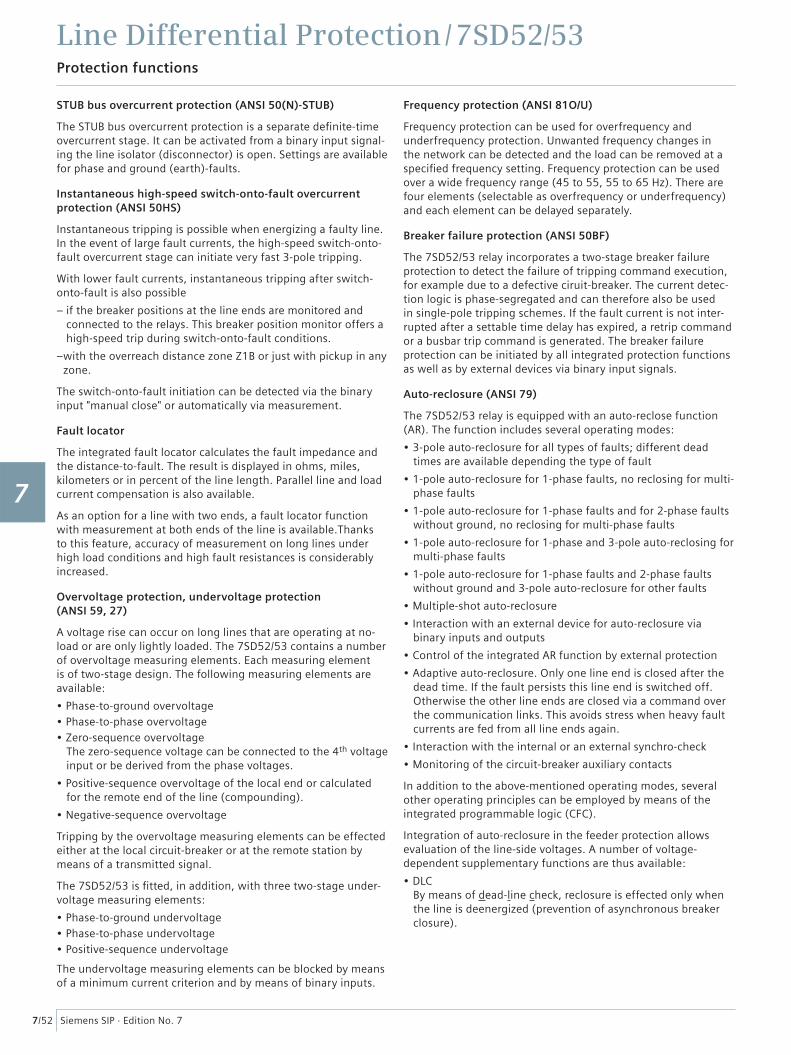
Fig. 7/56 Browser-aided commissioning: Phasor diagram
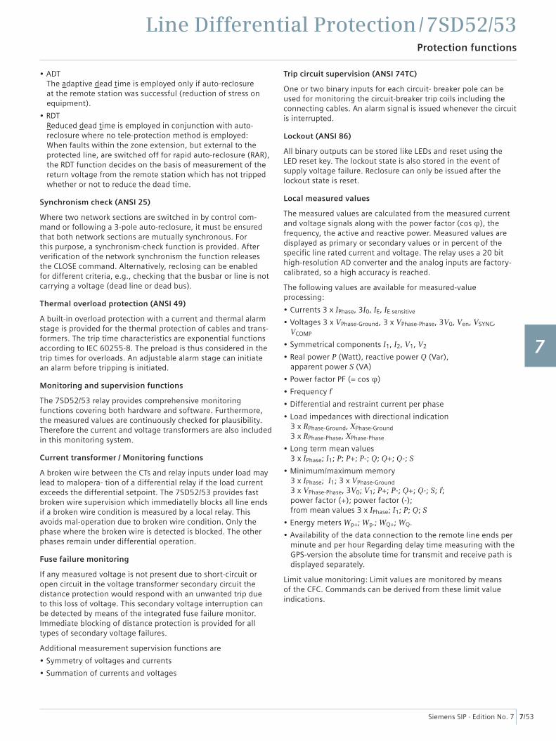
Fig. 7/57 Browser-aided commissioning: Differential protection tripping characteristic
Measured values at remote line ends
Every two seconds the currents and volt-ages are freezed at the same time at all line ends and transmitted via the commu-nication link. At a local line end, currents and voltages are thus available with their amount and phases (angle) locally and remotely. This allows checking the whole confi guration under load conditions. In addition, the differential and restraint currents are also displayed. Important communication measurements, such as delay time or faulty telegrams per minute/hour are also available as measurements. These measured values can be processed with the help of the CFC logic editor.
Commissioning
Special attention has been paid to commissioning. All binary inputs and outputs can be displayed and activated directly. This can simplify the wiring check signifi cantly for the user. The operational and fault events and the fault records are clearly arranged.
Furthermore, all currents and optional voltages and phases are available via communication link at the local relay and are displayed in the relay, with DIGSI 4 or with the Web Monitor.
The operational and fault events and fault records from all line ends share a common time tagging which allows to compare events registered in the different line ends on a common time base.
WEB Monitor – Internet technology simplifi es visualization
In addition to the universal DIGSI 4 operating program, the relay contains a WEB server that can be accessed via a telecommunication link using a browser (e.g. Internet Explorer). The advantage of this solution is to operate the unit with standard software tools and at the same time make use of the Intranet/Internet infrastructure. This program shows the protection topology and comprehensive measurements from local and remote line ends. Local and remote measurements are shown as phasors and the breaker positions of each line end are depicted. It is possible to check the correct connection of the current transformers or the correct vector group of a transformer.
Stability can be checked by using the operating characteristic as well as the calculated differential and restraint values in the browser windows.
If the distance protection is active, then the valid zone character-istic (quadrilateral/mho) is displayed.
Event log and trip log messages are also available. Remote control can be used, if the local front panel cannot be accessed.
LSP2
84
6.t
ifLS
P28
45
.tif
1
2
3
4
5
6
7
8
9
10
11
12
13
14
15
Line Differential Protection / 7SD52/53Protection functions
7/55Siemens SIP · Edition No. 7
Control and automation functions
Control
In addition to the protection functions, the SIPROTEC 4 units also support all control and monitoring functions that are required for operating medium-voltage or high-voltage substations.
The main application is reliable control of switching and other processes.
The status of primary equipment or auxiliary devices can be obtained from auxiliary contacts and communicated via binary inputs. Therefore it is possible to detect and indicate both the OPEN and CLOSED position or a fault or intermediate circuit-breaker or auxiliary contact position.
The switchgear or circuit-breaker can be controlled via: – integrated operator panel– binary inputs– substation control and protection system– DIGSI 4
Command processing
All the functionality of command processing is offered. This includes the processing of single and double commands with or without feedback, sophisticated monitoring of the control hardware and software, checking of the external process, control actions using functions such as runtime monitoring and automatic command termination after output. Here are some typical applications:
• Single and double commands using 1, 1 plus 1 common or 2 trip contacts
• User-defi nable bay interlocks
• Operating sequences combining several switching operations such as control of circuit-breakers, disconnectors and ground-ing switches
• Triggering of switching operations, indications or alarm by combination with existing information
Automation/user-defi ned logic
With integrated logic, the user can set, via a graphic interface (CFC), specifi c functions for the automation of switchgear or substation. Functions are activated via function keys, binary input or via communication interface.
Switching authority
Switching authority is determined according to parameters, communication or by key-operated switch (when available).
If a source is set to “LOCAL”, only local switching operations are possible. The following sequence of switching authority is laid down: “LOCAL”; DIGSI PC program, “REMOTE”
Every switching operation and change of breaker position is kept in the status indication memory. The switch command source, switching device, cause (i.e. spontaneous change or command) and result of a switching operation are retained.
Assignment of feedback to command
The positions of the circuit-breaker or switching devices and transformer taps are acquired by feedback. These indication inputs are logically assigned to the corresponding command outputs. The unit can therefore distinguish whether the indica-tion change is a consequence of switching operation or whether it is a spontaneous change of state (intermediate position).
Chatter disable
The chatter disable feature evaluates whether, in a confi gured period of time, the number of status changes of indication input exceeds a specifi ed fi gure. If exceeded, the indication input is blocked for a certain period, so that the event list will not record excessive operations.
Filter time
All binary indications can be subjected to a fi lter time (indication suppression).
Indication fi ltering and delay
Indications can be fi ltered or delayed.
Filtering serves to suppress brief changes in potential at the indication input. The indication is passed on only if the indica-tion voltage is still present after a set period of time. In the event of indication delay, there is a wait for a preset time. The information is passed on only if the indication voltage is still present after this time.
Indication derivation
A further indication (or a command) can be derived from an existing indication. Group indications can also be formed. The volume of information to the system interface can thus be reduced and restricted to the most important signals.
Transmission lockout
A data transmission lockout can be activated, so as to prevent transfer of information to the control center during work on a circuit bay.
Test operation
During commissioning, all indications can be passed to an automatic control system for test purposes.
1
2
3
4
5
6
7
8
9
10
11
12
13
14
15
Line Differential Protection / 7SD52/53Communication
7/56 Siemens SIP · Edition No. 7
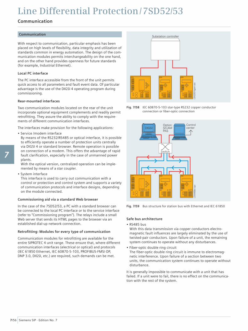
Fig. 7/58 IEC 60870-5-103 star-type RS232 copper conductor connection or fi ber-optic connection
Fig. 7/59 Bus structure for station bus with Ethernet and IEC 61850
Communication
With respect to communication, particular emphasis has been placed on high levels of fl exibility, data integrity and utilization of standards common in energy automation. The design of the com-munication modules permits interchangeability on the one hand, and on the other hand provides openness for future standards (for example, Industrial Ethernet).
Local PC interface
The PC interface accessible from the front of the unit permits quick access to all parameters and fault event data. Of particular advantage is the use of the DIGSI 4 operating program during commissioning.
Rear-mounted interfaces
Two communication modules located on the rear of the unit incorporate optional equipment complements and readily permit retrofi tting. They assure the ability to comply with the require-ments of different communication interfaces.
The interfaces make provision for the following applications:
• Service /modem interfaceBy means of the RS232/RS485 or optical interface, it is possible to effi ciently operate a number of protection units centrally via DIGSI 4 or standard browser. Remote operation is possible on connection of a modem. This offers the advantage of rapid fault clarifi cation, especially in the case of unmanned power plants.With the optical version, centralized operation can be imple-mented by means of a star coupler.
• System interface This interface is used to carry out communication with a control or protection and control system and supports a variety of communication protocols and interface designs, depending on the module connected.
Commissioning aid via a standard Web browser
In the case of the 7SD52/53, a PC with a standard browser can be connected to the local PC interface or to the service interface (refer to “Commissioning program”). The relays include a small Web server that sends its HTML pages to the browser via an established dial-up network connection.
Retrofi tting: Modules for every type of communication
Communication modules for retrofi tting are available for the entire SIPROTEC 4 unit range. These ensure that, where different communication interfaces (electrical or optical) and protocols (IEC 61850 Ethernet, IEC 60870-5-103, PROFIBUS-FMS/-DP, DNP 3.0, DIGSI, etc.) are required, such demands can be met.
Safe bus architecture
• RS485 busWith this data transmission via copper conductors electro-magnetic fault infl uences are largely eliminated by the use of twisted-pair conductors. Upon failure of a unit, the remaining system continues to operate without any disturbances.
• Fiber-optic double ring circuitThe fi ber-optic double ring circuit is immune to electromag-netic interference. Upon failure of a section between two units, the communication system continues to operate without disturbance.
It is generally impossible to communicate with a unit that has failed. If a unit were to fail, there is no effect on the communica-tion with the rest of the system.
1
2
3
4
5
6
7
8
9
10
11
12
13
14
15
Line Differential Protection / 7SD52/53Communication
7/57Siemens SIP · Edition No. 7
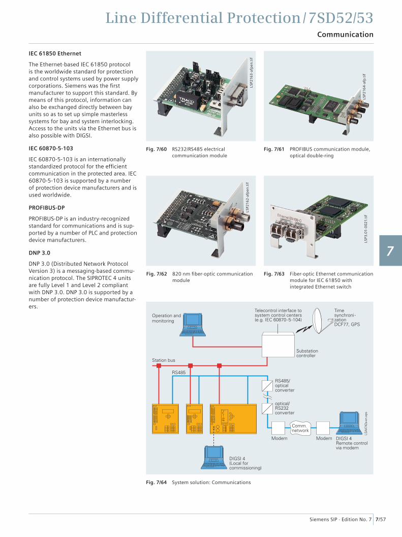
IEC 61850 Ethernet
The Ethernet-based IEC 61850 protocol is the worldwide standard for protection and control systems used by power supply corporations. Siemens was the fi rst manufacturer to support this standard. By means of this protocol, information can also be exchanged directly between bay units so as to set up simple masterless systems for bay and system interlocking. Access to the units via the Ethernet bus is also possible with DIGSI.
IEC 60870-5-103
IEC 60870-5-103 is an internationally standardized protocol for the effi cient communication in the protected area. IEC 60870-5-103 is supported by a number of protection device manufacturers and is used worldwide.
PROFIBUS-DP
PROFIBUS-DP is an industry-recognized standard for communications and is sup-ported by a number of PLC and protection device manufacturers.
DNP 3.0
DNP 3.0 (Distributed Network Protocol Version 3) is a messaging-based commu-nication protocol. The SIPROTEC 4 units are fully Level 1 and Level 2 compliant with DNP 3.0. DNP 3.0 is supported by a number of protection device manufactur-ers.
Fig. 7/60 RS232/RS485 electrical communication module
Fig. 7/61 PROFIBUS communication module, optical double-ring
LSP2
163
-afp
en.t
if
LSP3
.01-
00
21.t
ifLS
P216
4-a
fp.t
if
Fig. 7/62 820 nm fi ber-optic communication module
Fig. 7/63 Fiber-optic Ethernet communication module for IEC 61850 with integrated Ethernet switch
Fig. 7/64 System solution: Communications
LSP2
162
-afp
en.t
if
1
2
3
4
5
6
7
8
9
10
11
12
13
14
15
Line Differential Protection / 7SD52/53Communication
7/58 Siemens SIP · Edition No. 7
System solutions for protection and station control
Together with the SICAM power automation system, SIPROTEC 4 can be used with PROFIBUS-FMS. Over the low-cost electrical RS485 bus, or interference-free via the optical double ring, the units exchange information with the control system.
Units featuring IEC 60870-5-103 interfaces can be connected to SICAM in parallel via the RS485 bus or radially by fi ber-optic link. Through this interface, the system is open for the connection of units of other manufacturers (see Fig. 7/58).
Because of the standardized interfaces, SIPROTEC units can also be integrated into systems of other manufacturers or in SIMATIC. Electrical RS485 or optical interfaces are available. The optimum physical data transfer medium can be chosen thanks to opto-electrical converters. Thus, the RS485 bus allows low-cost wiring in the cubicles and an interference-free optical connection to the master can be established.
For IEC 61850, an interoperable system solution is offered with SICAM PAS. Via the 100 Mbits/s Ethernet bus, the units are linked with PAS electrically or optically to the station PC. The interface is standardized, thus also enabling direct connection of units of other manufacturers to the Ethernet bus. With IEC 61850, however, the units can also be used in other manufacturers' systems (see Fig. 7/59).
Via modem and service interface, the protection engineer has access to the protection devices at all times. This permits remote maintenance and diagnosis (cyclic testing).
Parallel to this, local communication is possible, for example, during a major inspection.
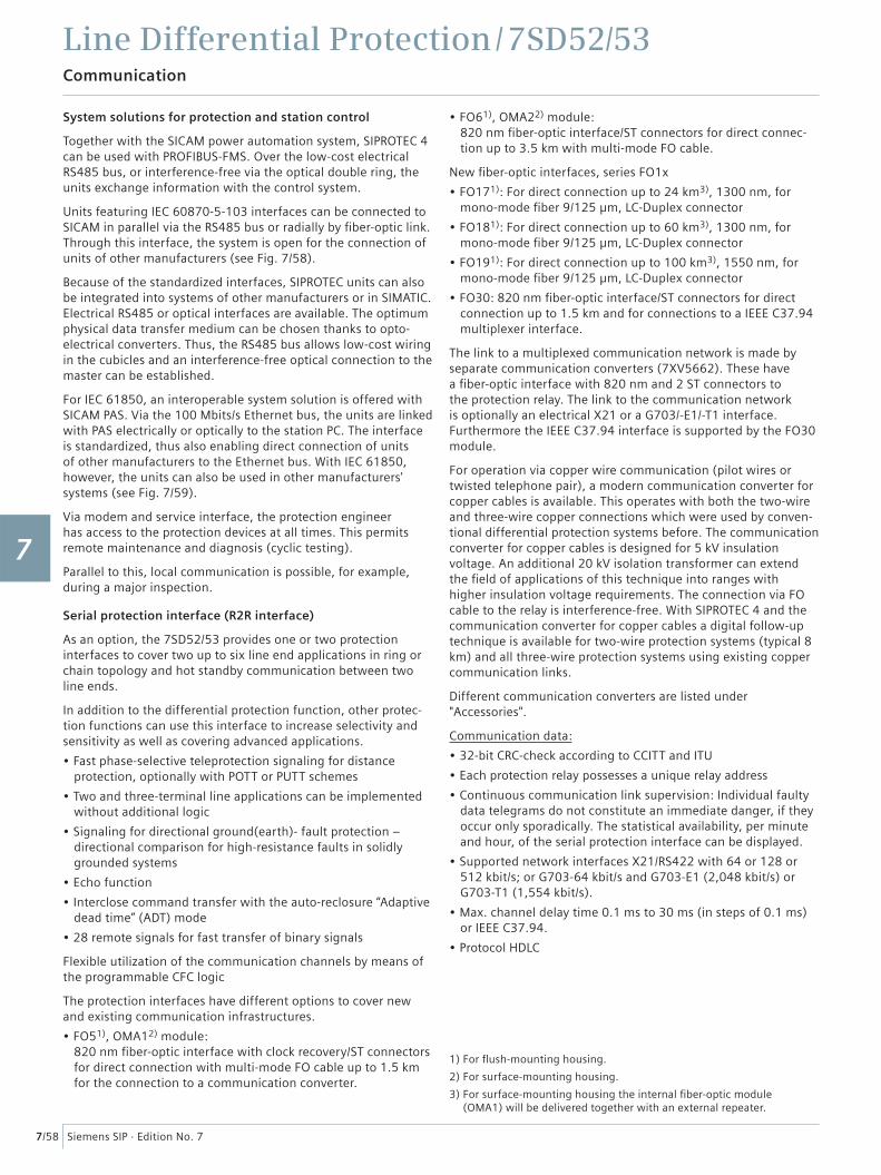
Serial protection interface (R2R interface)
As an option, the 7SD52/53 provides one or two protection interfaces to cover two up to six line end applications in ring or chain topology and hot standby communication between two line ends.
In addition to the differential protection function, other protec-tion functions can use this interface to increase selectivity and sensitivity as well as covering advanced applications.
• Fast phase-selective teleprotection signaling for distance protection, optionally with POTT or PUTT schemes
• Two and three-terminal line applications can be implemented without additional logic
• Signaling for directional ground(earth)- fault protection – directional comparison for high-resistance faults in solidly grounded systems
• Echo function
• Interclose command transfer with the auto-reclosure “Adaptive dead time” (ADT) mode
• 28 remote signals for fast transfer of binary signals
Flexible utilization of the communication channels by means of the programmable CFC logic
The protection interfaces have different options to cover new and existing communication infrastructures.
• FO51), OMA12) module: 820 nm fi ber-optic interface with clock recovery/ST connectors for direct connection with multi-mode FO cable up to 1.5 km for the connection to a communication converter.
• FO61), OMA22) module: 820 nm fi ber-optic interface/ST connectors for direct connec-tion up to 3.5 km with multi-mode FO cable.
New fi ber-optic interfaces, series FO1x
• FO171): For direct connection up to 24 km3), 1300 nm, for mono-mode fi ber 9/125 μm, LC-Duplex connector
• FO181): For direct connection up to 60 km3), 1300 nm, for mono-mode fi ber 9/125 μm, LC-Duplex connector
• FO191): For direct connection up to 100 km3), 1550 nm, for mono-mode fi ber 9/125 μm, LC-Duplex connector
• FO30: 820 nm fi ber-optic interface/ST connectors for direct connection up to 1.5 km and for connections to a IEEE C37.94 multiplexer interface.
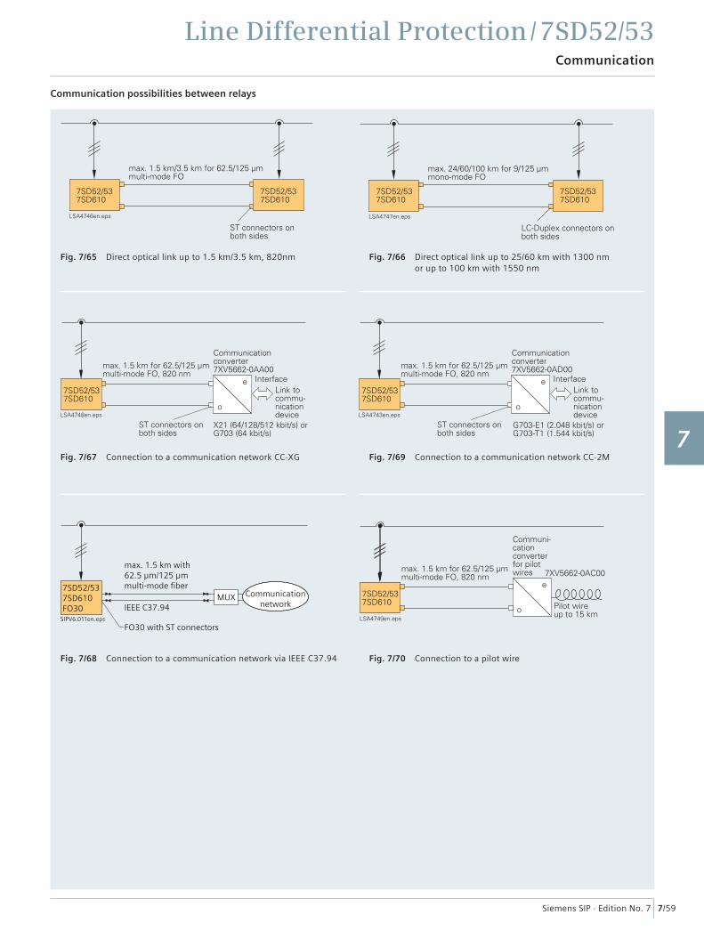
The link to a multiplexed communication network is made by separate communication converters (7XV5662). These have a fi ber-optic interface with 820 nm and 2 ST connectors to the protection relay. The link to the communication network is optionally an electrical X21 or a G703/-E1/-T1 interface. Furthermore the IEEE C37.94 interface is supported by the FO30 module.
For operation via copper wire communication (pilot wires or twisted telephone pair), a modern communication converter for copper cables is available. This operates with both the two-wire and three-wire copper connections which were used by conven-tional differential protection systems before. The communication converter for copper cables is designed for 5 kV insulation voltage. An additional 20 kV isolation transformer can extend the fi eld of applications of this technique into ranges with higher insulation voltage requirements. The connection via FO cable to the relay is interference-free. With SIPROTEC 4 and the communication converter for copper cables a digital follow-up technique is available for two-wire protection systems (typical 8 km) and all three-wire protection systems using existing copper communication links.
Different communication converters are listed under "Accessories".
Communication data:
• 32-bit CRC-check according to CCITT and ITU
• Each protection relay possesses a unique relay address
• Continuous communication link supervision: Individual faulty data telegrams do not constitute an immediate danger, if they occur only sporadically. The statistical availability, per minute and hour, of the serial protection interface can be displayed.
• Supported network interfaces X21/RS422 with 64 or 128 or 512 kbit/s; or G703-64 kbit/s and G703-E1 (2,048 kbit/s) or G703-T1 (1,554 kbit/s).
• Max. channel delay time 0.1 ms to 30 ms (in steps of 0.1 ms) or IEEE C37.94.
• Protocol HDLC
1) For fl ush-mounting housing.
2) For surface-mounting housing.
3) For surface-mounting housing the internal fi ber-optic module (OMA1) will be delivered together with an external repeater.
1
2
3
4
5
6
7
8
9
10
11
12
13
14
15
Line Differential Protection / 7SD52/53Communication
7/59Siemens SIP · Edition No. 7
Communication possibilities between relays
7SD52/537SD610FO30
SIPV6.011en.eps
Communicationnetwork
max. 1.5 km with62.5 μm/125 μmmulti-mode fiber
FO30 with ST connectors
IEEE C37.94MUX
Fig. 7/65 Direct optical link up to 1.5 km/3.5 km, 820nm Fig. 7/66 Direct optical link up to 25/60 km with 1300 nm or up to 100 km with 1550 nm
Fig. 7/67 Connection to a communication network CC-XG
Fig. 7/68 Connection to a communication network via IEEE C37.94
Fig. 7/69 Connection to a communication network CC-2M
Fig. 7/70 Connection to a pilot wire
1
2
3
4
5
6
7
8
9
10
11
12
13
14
15
Line Differential Protection / 7SD52/53Typical connection
7/60 Siemens SIP · Edition No. 7
Typical connection
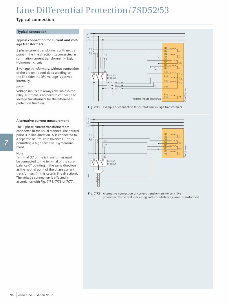
Typical connection for current and volt-age transformers
3 phase current transformers with neutral point in the line direction, I4 connected as summation current transformer (= 3I0): Holmgreen circuit
3 voltage transformers, without connection of the broken (open) delta winding on the line side; the 3V0 voltage is derived internally.
Note:Voltage inputs are always available in the relay. But there is no need to connect it to voltage transformers for the differential protection function.
Alternative current measurement
The 3 phase current transformers are connected in the usual manner. The neutral point is in line direction. I4 is connected to a separate neutral core-balance CT, thus permitting a high sensitive 3I0 measure-ment.
Note: Terminal Q7 of the I4 transformer must be connected to the terminal of the core-balance CT pointing in the same direction as the neutral point of the phase current transformers (in this case in line direction). The voltage connection is effected in accordance with Fig. 7/71, 7/76 or 7/77.
Fig. 7/71 Example of connection for current and voltage transformers
Fig. 7/72 Alternative connection of current transformers for sensitive ground(earth)-current measuring with core-balance current transformers
1
2
3
4
5
6
7
8
9
10
11
12
13
14
15
Line Differential Protection / 7SD52/53Typical connection
7/61Siemens SIP · Edition No. 7
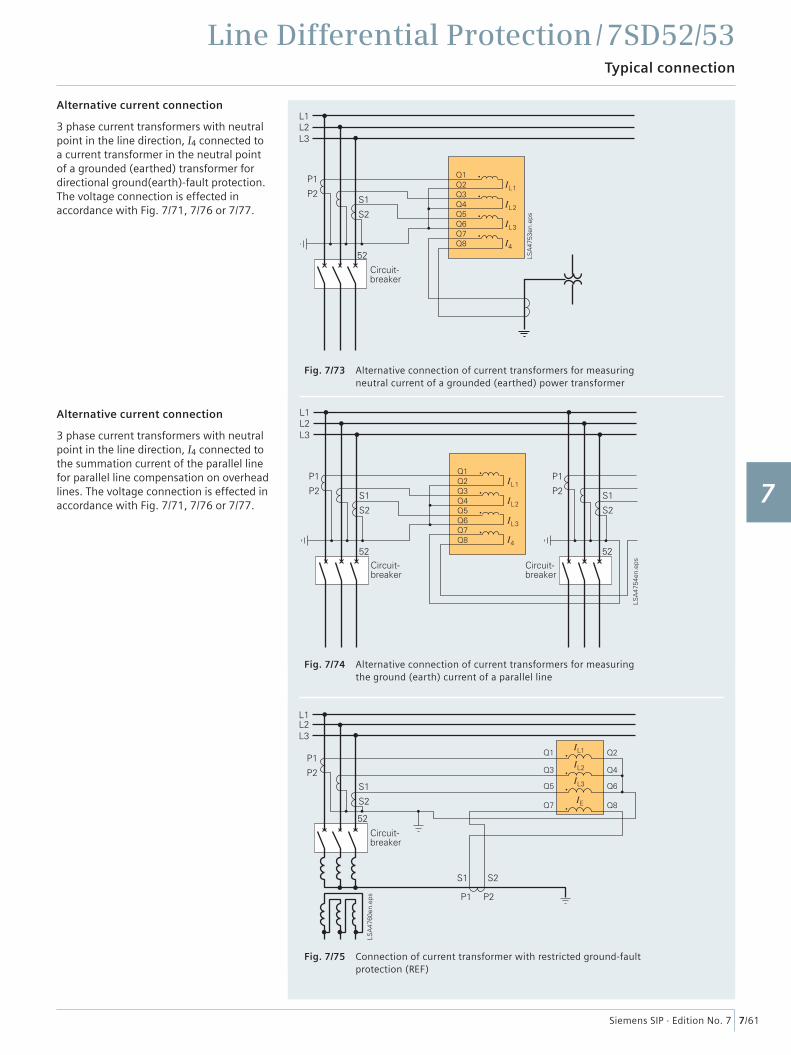
Alternative current connection
3 phase current transformers with neutral point in the line direction, I4 connected to a current transformer in the neutral point of a grounded (earthed) transformer for directional ground(earth)-fault protection. The voltage connection is effected in accordance with Fig. 7/71, 7/76 or 7/77.
Alternative current connection
3 phase current transformers with neutral point in the line direction, I4 connected to the summation current of the parallel line for parallel line compensation on overhead lines. The voltage connection is effected in accordance with Fig. 7/71, 7/76 or 7/77.
Fig. 7/73 Alternative connection of current transformers for measuring neutral current of a grounded (earthed) power transformer
Fig. 7/74 Alternative connection of current transformers for measuring the ground (earth) current of a parallel line
Fig. 7/75 Connection of current transformer with restricted ground-faultprotection (REF)
1
2
3
4
5
6
7
8
9
10
11
12
13
14
15
Line Differential Protection / 7SD52/53Typical connection
7/62 Siemens SIP · Edition No. 7
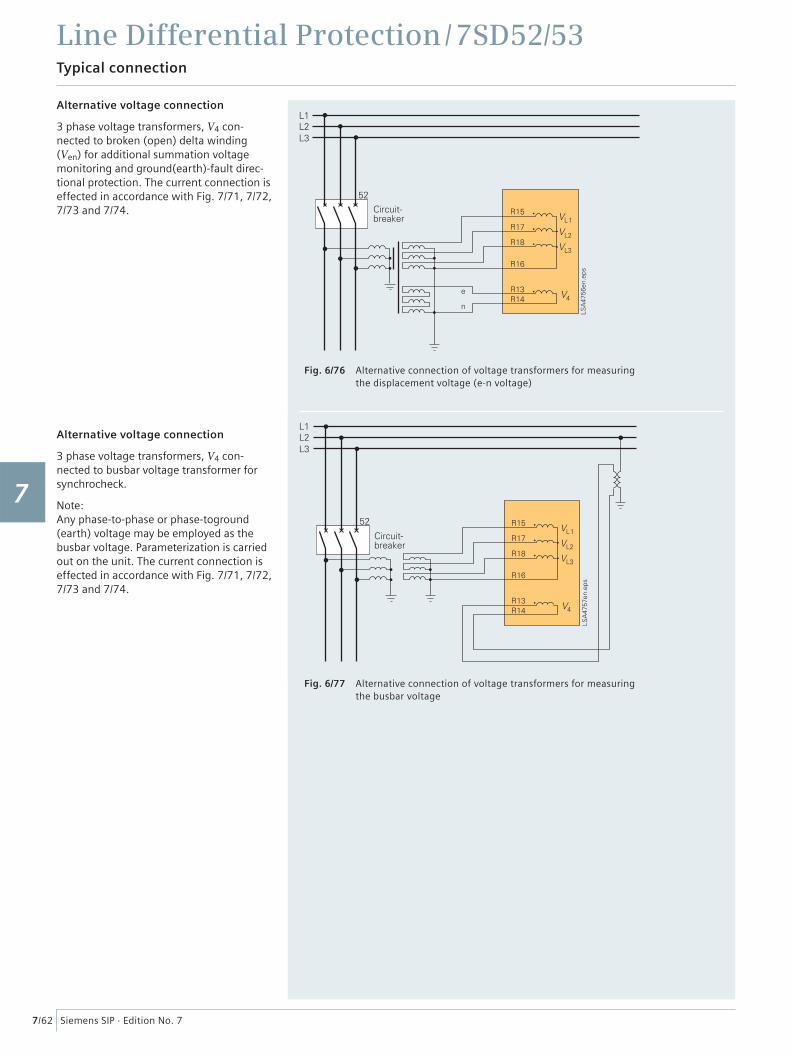
Alternative voltage connection
3 phase voltage transformers, V4 con-nected to broken (open) delta winding (Ven) for additional summation voltage monitoring and ground(earth)-fault direc-tional protection. The current connection is effected in accordance with Fig. 7/71, 7/72, 7/73 and 7/74.
Alternative voltage connection
3 phase voltage transformers, V4 con-nected to busbar voltage transformer for synchrocheck.
Note: Any phase-to-phase or phase-toground (earth) voltage may be employed as the busbar voltage. Parameterization is carried out on the unit. The current connection is effected in accordance with Fig. 7/71, 7/72, 7/73 and 7/74.
Fig. 6/76 Alternative connection of voltage transformers for measuring the displacement voltage (e-n voltage)
Fig. 6/77 Alternative connection of voltage transformers for measuring the busbar voltage
1
2
3
4
5
6
7
8
9
10
11
12
13
14
15
Line Differential Protection / 7SD52/53Technical data
7/63Siemens SIP · Edition No. 7
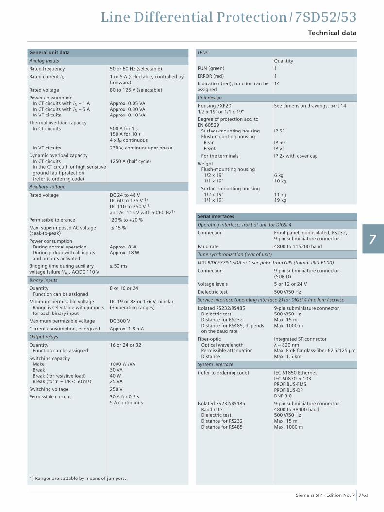
General unit data
Analog inputs
Rated frequency
Rated current IN
Rated voltage
Power consumption In CT circuits with IN = 1 A In CT circuits with IN = 5 A In VT circuits
Thermal overload capacity In CT circuits
In VT circuits
Dynamic overload capacity In CT circuits In the CT circuit for high sensitive ground-fault protection (refer to ordering code)
50 or 60 Hz (selectable)
1 or 5 A (selectable, controlled by fi rmware)
80 to 125 V (selectable)
Approx. 0.05 VAApprox. 0.30 VAApprox. 0.10 VA
500 A for 1 s150 A for 10 s4 x IN continuous
230 V, continuous per phase
1250 A (half cycle)
Auxiliary voltage
Rated voltage
Permissible tolerance
Max. superimposed AC voltage (peak-to-peak)
Power consumption During normal operation During pickup with all inputs and outputs activated
Bridging time during auxiliary voltage failure Vaux AC/DC 110 V
DC 24 to 48 VDC 60 to 125 V 1)
DC 110 to 250 V 1)
and AC 115 V with 50/60 Hz1)
-20 % to +20 %
≤ 15 %
Approx. 8 WApprox. 18 W
≥ 50 ms
Binary inputs
Quantity Function can be assigned
Minimum permissible voltage Range is selectable with jumpers for each binary input
Maximum permissible voltage
Current consumption, energized
8 or 16 or 24
DC 19 or 88 or 176 V, bipolar(3 operating ranges)
DC 300 V
Approx. 1.8 mA
Output relays
Quantity Function can be assigned
Switching capacity Make Break Break (for resistive load) Break (for τ = L/R ≤ 50 ms)
Switching voltage
Permissible current
16 or 24 or 32
1000 W /VA30 VA40 W25 VA
250 V
30 A for 0.5 s5 A continuous
1) Ranges are settable by means of jumpers.
LEDs
RUN (green)
ERROR (red)
Indication (red), function can be assigned
Quantity
1
1
14
Unit design
Housing 7XP20 1/2 x 19" or 1/1 x 19"
Degree of protection acc. to EN 60529 Surface-mounting housing Flush-mounting housing Rear Front
For the terminals
Weight Flush-mounting housing 1/2 x 19" 1/1 x 19"
Surface-mounting housing 1/2 x 19" 1/1 x 19"
See dimension drawings, part 14
IP 51
IP 50IP 51
IP 2x with cover cap
6 kg10 kg
11 kg19 kg
Serial interfaces
Operating interface, front of unit for DIGSI 4
Connection
Baud rate
Front panel, non-isolated, RS232,9-pin subminiature connector
4800 to 115200 baud
Time synchronization (rear of unit)
IRIG-B/DCF77/SCADA or 1 sec pulse from GPS (format IRIG-B000)
Connection
Voltage levels
Dielectric test
9-pin subminiature connector (SUB-D)
5 or 12 or 24 V
500 V/50 Hz
Service interface (operating interface 2) for DIGSI 4 /modem / service
Isolated RS232/RS485 Dielectric test Distance for RS232 Distance for RS485, depends on the baud rate
Fiber-optic Optical wavelength Permissible attenuation Distance
9-pin subminiature connector500 V/50 HzMax. 15 mMax. 1000 m
Integrated ST connectorλ = 820 nmMax. 8 dB for glass-fi ber 62.5/125 µmMax. 1.5 km
System interface
(refer to ordering code)
Isolated RS232/RS485 Baud rate Dielectric test Distance for RS232 Distance for RS485
IEC 61850 EthernetIEC 60870-5-103PROFIBUS-FMS PROFIBUS-DPDNP 3.0
9-pin subminiature connector4800 to 38400 baud500 V/50 HzMax. 15 mMax. 1000 m
1
2
3
4
5
6
7
8
9
10
11
12
13
14
15
Line Differential Protection / 7SD52/53Technical data
7/64 Siemens SIP · Edition No. 7
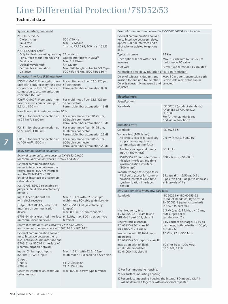
System interface, continued
PROFIBUS RS485 Dielectric test Baud rate Distance
PROFIBUS fi ber-optic2)
Only for fl ush-mounting housing For surface-mounting housing Baud rate Optical wavelength Permissible attenuation Distance
500 V/50 HzMax. 12 Mbaud1 km at 93.75 kB; 100 m at 12 MB
ST connectorOptical interface with OLM2)
Max. 1.5 Mbaudλ = 820 nmMax. 8 dB for glass-fi ber 62.5/125 µm500 kB/s 1.6 km, 1500 kB/s 530 m
Protection interface (R2R interface)
FO51), OMA12): Fiber-optic inter-face with clock recovery for direct connection up to 1.5 km or for connection to a communication converter, 820 nm
FO61), OMA22): Fiber-optic inter- face for direct connection up to 3.5 km, 820 nm
For multi-mode fi ber 62.5/125 µm,ST connectorsPermissible fi ber attenuation 8 dB
For multi-mode fi ber 62.5/125 µm,ST connectorsPermissible fi ber attenuation 16 dB
New fi ber-optic interfaces, series FO1x
FO171): for direct connection up to 24 km3), 1300 nm
FO181): for direct connection up to 60 km3), 1300 nm
FO191): for direct connection up to 100 km3), 1550 nm
For mono-mode fi ber 9/125 µm,LC-Duplex connectorPermissible fi ber attenuation 13 dB
For mono-mode fi ber 9/125 µm,LC-Duplex connectorPermissible fi ber attenuation 29 dB
For mono-mode fi ber 9/125 µm,LC-Duplex connectorPermissible fi ber attenuation 29 dB
Relay communication equipment
External communication converter 7XV5662-0AA00for communication networks X21/ G703-64 kbit/s
External communication con-verter to interface between the relays, optical 820 nm interface and the X21(RS422) G703-64 kbit/s interface of a communi-cation device
X21/G703, RS422 selectable by jumpers. Baud rate selectable by jumpers
Input: fi ber-optic 820 nm with clock recovery
Output: X21 (RS422) electrical interface on communication device
G703-64 kbit/s electrical interface on communication device
Max. 1.5 km with 62.5/125 µm multi-mode FO cable to device side
64/128/512 kbit (selectable by jumper)max. 800 m, 15-pin connector
64 kbit/s, max. 800 m, screw-type terminal
External communication converter 7XV5662-0AD00for communication networks with G703-E1 or G703-T1
External communication conver-ter to interface between the re-lays, optical 820 nm interface and G703-E1 or G703-T1 interface of a communication network.
Inputs: 2 fi ber-optic inputs 820 nm, 1RS232 input
Output:G703.5G703.6
Electrical interface on communi-cation network
Max. 1.5 km with 62.5/125µm multi-mode 1 FO cable to device side
E1: 2,048 kbit/sT1: 1,554 kbit/s
max. 800 m, screw-type terminal
External communication converter 7XV5662-0AC00 for pilotwires
External communication conver-ter to interface between relays, optical 820 nm interface and a pilot wire or twisted telephone pair.
Typical distance
Fiber-optic 820 nm with clock recovery
Pilot wire
15 km
Max. 1.5 km with 62.5/125 µm multi-mode FO cable
Screw-type terminal 5 kV isolated
Permissible time delay (duration of data transmission)
Delay of telegrams due to trans-mission for one unit to the other.Delay is constantly measured and adjusted
Max. 30 ms per transmission path Permissible max. value can be selected
Electrical tests
Specifi cations
Standards IEC 60255 (product standards)ANSI/IEEE C37.90.0/.1/.2UL 508For further standards see “Individual functions”
Insulation tests
Standards
Voltage test (100 % test) All circuits except for auxiliary supply, binary inputs and communication interfaces
Auxiliary voltage and binary inputs (100 % test)
RS485/RS232 rear side commu-nication interfaces and time synchronization interface (100 % test)
Impulse voltage test (type test) All circuits except for commu-
nication interfaces and time synchronization interface, class III
IEC 60255-5
2.5 kV (r.m.s.), 50/60 Hz
DC 3.5 kV
500 V (r.m.s.), 50/60 Hz
5 kV (peak); 1.2/50 μs; 0.5 J3 positive and 3 negative impulses at intervals of 5 s
EMC tests for noise immunity; type tests
Standards
High frequency test IEC 60255-22-1, class III and VDE 0435 part 303, class III
Electrostatic discharge IEC 60255-22-2, class IV EN 61000-4-2, class IV
Irradiation with RF fi eld, non-modulatedIEC 60255-22-3 (report), class III
Irradiation with RF fi eld, amplitude-modulated IEC 61000-4-3, class III
IEC 60255-6, IEC 60255-22 (product standards) (type tests) EN 50082-2 (generic standard)DIN 57435 part 303
2.5 kV (peak); 1 MHz; τ = 15 ms; 400 surges per s;test duration 2 s
8 kV contact discharge; 15 kV air discharge; both polarities; 150 pF; Ri = 330 Ω
10 V/m; 27 to 500 MHz
10 V/m; 80 to 1000 MHz; 80 % AM; 1 kHz
1) For fl ush-mounting housing.
2) For surface-mounting housing.
3) For surface-mounting housing the internal FO module OMA1 will be delivered together with an external repeater.
1
2
3
4
5
6
7
8
9
10
11
12
13
14
15
Line Differential Protection / 7SD52/53Technical data
7/65Siemens SIP · Edition No. 7
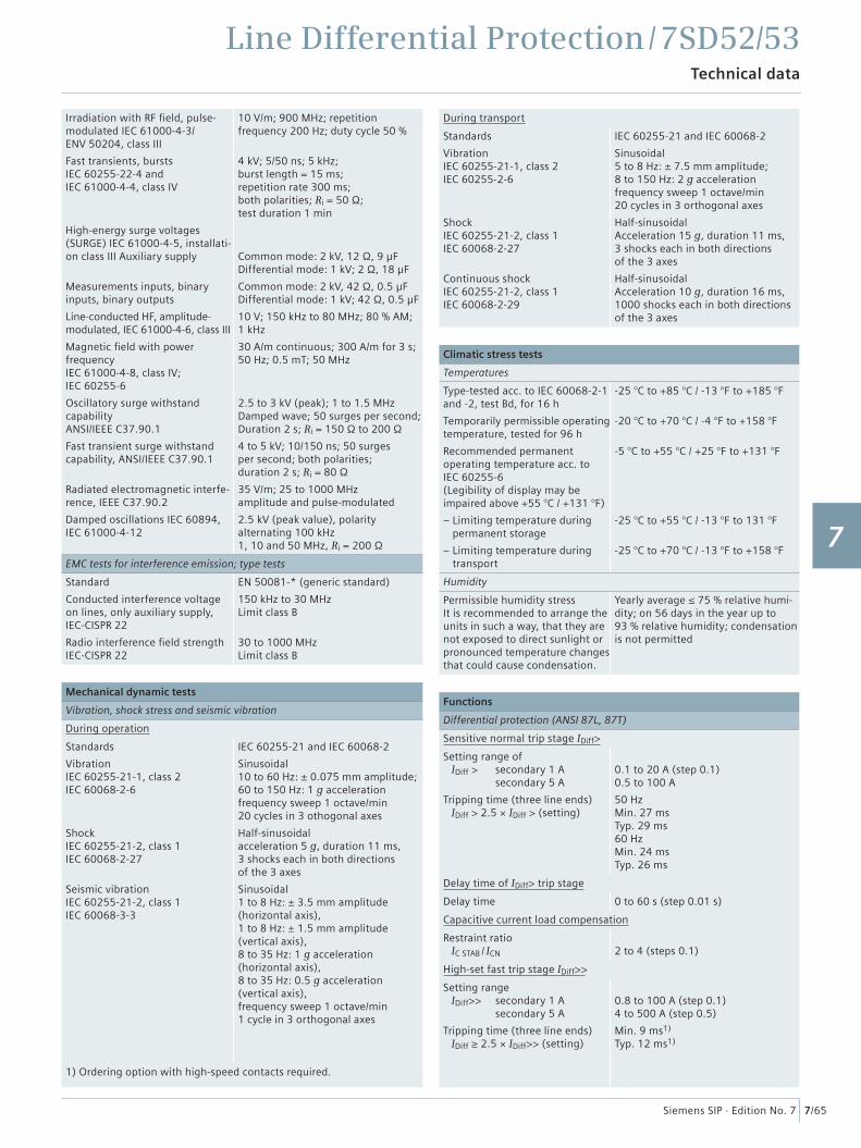
Irradiation with RF fi eld, pulse-modulated IEC 61000-4-3/ ENV 50204, class III
Fast transients, bursts IEC 60255-22-4 and IEC 61000-4-4, class IV
High-energy surge voltages (SURGE) IEC 61000-4-5, installati-on class III Auxiliary supply
Measurements inputs, binary inputs, binary outputs
Line-conducted HF, amplitude-modulated, IEC 61000-4-6, class III
Magnetic fi eld with power frequencyIEC 61000-4-8, class IV; IEC 60255-6
Oscillatory surge withstand capabilityANSI/IEEE C37.90.1
Fast transient surge withstand capability, ANSI/IEEE C37.90.1
Radiated electromagnetic interfe-rence, IEEE C37.90.2
Damped oscillations IEC 60894, IEC 61000-4-12
10 V/m; 900 MHz; repetition frequency 200 Hz; duty cycle 50 %
4 kV; 5/50 ns; 5 kHz; burst length = 15 ms;repetition rate 300 ms; both polarities; Ri = 50 Ω; test duration 1 min
Common mode: 2 kV, 12 Ω, 9 µFDifferential mode: 1 kV; 2 Ω, 18 µF
Common mode: 2 kV, 42 Ω, 0.5 µFDifferential mode: 1 kV; 42 Ω, 0.5 µF
10 V; 150 kHz to 80 MHz; 80 % AM; 1 kHz
30 A/m continuous; 300 A/m for 3 s; 50 Hz; 0.5 mT; 50 MHz
2.5 to 3 kV (peak); 1 to 1.5 MHzDamped wave; 50 surges per second;Duration 2 s; Ri = 150 Ω to 200 Ω
4 to 5 kV; 10/150 ns; 50 surges per second; both polarities; duration 2 s; Ri = 80 Ω
35 V/m; 25 to 1000 MHzamplitude and pulse-modulated
2.5 kV (peak value), polarity alternating 100 kHz1, 10 and 50 MHz, Ri = 200 Ω
EMC tests for interference emission; type tests
Standard
Conducted interference voltage on lines, only auxiliary supply,IEC-CISPR 22
Radio interference fi eld strengthIEC-CISPR 22
EN 50081-* (generic standard)
150 kHz to 30 MHzLimit class B
30 to 1000 MHzLimit class B
Mechanical dynamic tests
Vibration, shock stress and seismic vibration
During operation
Standards
Vibration IEC 60255-21-1, class 2 IEC 60068-2-6
Shock IEC 60255-21-2, class 1 IEC 60068-2-27
Seismic vibration IEC 60255-21-2, class 1 IEC 60068-3-3
IEC 60255-21 and IEC 60068-2
Sinusoidal10 to 60 Hz: ± 0.075 mm amplitude;60 to 150 Hz: 1 g accelerationfrequency sweep 1 octave/min20 cycles in 3 othogonal axes
Half-sinusoidalacceleration 5 g, duration 11 ms, 3 shocks each in both directions of the 3 axes
Sinusoidal1 to 8 Hz: ± 3.5 mm amplitude (horizontal axis),1 to 8 Hz: ± 1.5 mm amplitude (vertical axis),8 to 35 Hz: 1 g acceleration(horizontal axis),8 to 35 Hz: 0.5 g acceleration (vertical axis),frequency sweep 1 octave/min1 cycle in 3 orthogonal axes
1) Ordering option with high-speed contacts required.
During transport
Standards
Vibration IEC 60255-21-1, class 2 IEC 60255-2-6
Shock IEC 60255-21-2, class 1 IEC 60068-2-27
Continuous shock IEC 60255-21-2, class 1 IEC 60068-2-29
IEC 60255-21 and IEC 60068-2
Sinusoidal5 to 8 Hz: ± 7.5 mm amplitude;8 to 150 Hz: 2 g accelerationfrequency sweep 1 octave/min20 cycles in 3 orthogonal axes
Half-sinusoidalAcceleration 15 g, duration 11 ms, 3 shocks each in both directions of the 3 axes
Half-sinusoidalAcceleration 10 g, duration 16 ms, 1000 shocks each in both directions of the 3 axes
Climatic stress tests
Temperatures
Type-tested acc. to IEC 60068-2-1 and -2, test Bd, for 16 h
Temporarily permissible operating temperature, tested for 96 h
Recommended permanent operating temperature acc. to IEC 60255-6(Legibility of display may be impaired above +55 °C / +131 °F)
– Limiting temperature during permanent storage
– Limiting temperature during transport
-25 °C to +85 °C / -13 °F to +185 °F
-20 °C to +70 °C / -4 °F to +158 °F
-5 °C to +55 °C / +25 °F to +131 °F
-25 °C to +55 °C / -13 °F to 131 °F
-25 °C to +70 °C / -13 °F to +158 °F
Humidity
Permissible humidity stressIt is recommended to arrange the units in such a way, that they are not exposed to direct sunlight or pronounced temperature changes that could cause condensation.
Yearly average ≤ 75 % relative humi-dity; on 56 days in the year up to 93 % relative humidity; condensation is not permitted
Functions
Differential protection (ANSI 87L, 87T)
Sensitive normal trip stage IDiff>
Setting range of IDiff > secondary 1 A secondary 5 A
Tripping time (three line ends) IDiff > 2.5 × IDiff > (setting)
0.1 to 20 A (step 0.1)0.5 to 100 A
50 HzMin. 27 msTyp. 29 ms60 HzMin. 24 msTyp. 26 ms
Delay time of IDiff> trip stage
Delay time 0 to 60 s (step 0.01 s)
Capacitive current load compensation
Restraint ratio IC STAB / ICN 2 to 4 (steps 0.1)
High-set fast trip stage IDiff>>
Setting range IDiff>> secondary 1 A secondary 5 A
Tripping time (three line ends) IDiff ≥ 2.5 × IDiff>> (setting)
0.8 to 100 A (step 0.1)4 to 500 A (step 0.5)
Min. 9 ms1)
Typ. 12 ms1)
1
2
3
4
5
6
7
8
9
10
11
12
13
14
15
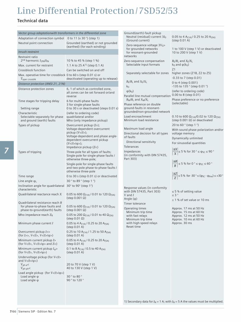
Line Differential Protection / 7SD52/53Technical data
7/66 Siemens SIP · Edition No. 7
Vector group adaptationwith transformers in the differential zone
Adaptation of connection symbol
Neutral point connection
0 to 11 (x 30 °) (step 1)
Grounded (earthed) or not grounded (earthed) (for each winding)
Inrush restraint
Restraint ratio 2nd harmonic I2fN/IfN
Max. current for restraint
Crossblock function
Max. operative time for crossblock Toper crossblk
10 % to 45 % (step 1 %)
1.1 A to 25 A1) (step 0.1 A)
Can be switched on and off
0 to 60 s (step 0.01 s) or deactivated (operating up to release)
Distance protection (ANSI 21, 21N)
Distance protection zones
Time stages for tripping delay
Setting range
Characteristic Selectable separately for phase and ground (earth) faults
Types of pickup
Types of tripping
Time range
Line angle φL
Inclination angle for quadrilateral characteristic
Quadrilateral reactance reach X
Quadrilateral resistance reach R for phase-to-phase faults and phase-to-ground(earth) faults
Mho impedance reach ZR
Minimum phase current I
Overcurrent pickup I>> (for I>>, V</I>, V</I>/φ>)
Minimum current pickup I> (for V</I>, V</I>/φ> and Z<)
Minimum current pickup Iφ>(for V</I>, V</I>/φ>)
Undervoltage pickup (for V</I> and V</I>/φ>) Vph-e< Vph-ph<
Load angle pickup (for V</I>/φ>) Load angle φ Load angle φ
6, 1 of which as controlled zone, all zones can be set forward or/and reverse
6 for multi-phase faults3 for single-phase faults0 to 30 s or deactivated (steps 0.01 s)
(refer to ordering code)quadrilateral and/orMho (only impedance pickup)
Overcurrent pickup (I>); Voltage-dependent overcurrent pickup (V</I>); Voltage-dependent and phase angle-dependent overcurrent pickup (V</I>/φ>); Impedance pickup (Z<)
Three-pole for all types of faults;Single-pole for single-phase faults / otherwise three-pole;
Single-pole for single-phase faults and two-pole phase-to-phase faults / otherwise three-pole
0 to 30 s (step 0.01 s) or deactivated
30 ° to 89 ° (step 1 °)
30° to 90° (step 1°)
0.05 to 600 Ω(1A) / 0.01 to 120 Ω(5A) (step 0.001 Ω)
0.05 to 600 Ω(1A) / 0.01 to 120 Ω(5A)(step 0.001 Ω)
0.05 to 200 Ω(1A) / 0.01 to 40 Ω(5A)(step 0.01 Ω)
0.05 to 4 A(1A) / 0.25 to 20 A(5A)(step 0.01 A)
0.25 to 10 A(1A) / 1.25 to 50 A(5A) (step 0.01 A)
0.05 to 4 A(1A) / 0.25 to 20 A(5A) (step 0.01 A)
0.1 to 8 A(1A) / 0.5 to 40 A(5A) (step 0.01 A)
20 to 70 V (step 1 V)40 to 130 V (step 1 V)
30 ° to 80 °90 ° to 120 °
Ground(earth)-fault pickup Neutral (residual) current 3I0 (Ground current)
Zero-sequence voltage 3V0> for grounded networks for resonant-grounded networks
Zero-sequence compensation Selectable input formats
Separately selectable for zones
RE/RL and XE/XL
k0
φ(k0)
Parallel line mutual compensation RM/RL and XM/XL
Phase reference on doubleground-faults in resonant-grounded/non-grounded network
Load encroachmentMinimum load resistance
Maximum load angle
Directional decision for all types of faults
Directional sensitivity
Tolerances
Impedances(in conformity with DIN 57435,Part 303)
Response values (in conformitywith DIN 57435, Part 303)V and IAngle (φ)
Timer tolerance
Operating times Minimum trip time with fast relays Minimum trip time with high-speed relays Reset time
0.05 to 4 A(1A) / 0.25 to 20 A(5A)(step 0.01 A)
1 to 100 V (step 1 V) or deactivated10 to 200 V (step 1 V)
RE/RL and XE/XLk0 and φ(k0)
Z1higher zones (Z1B, Z2 to Z5)
-0.33 to 7 (step 0.01)
0 to 4 (step 0.001)-135 to 135 ° (step 0.01 °)
(refer to ordering code)0.00 to 8 (step 0.01)
Phase preference or no preference(selectable)
0.10 to 600 Ω(1A)/0.02 to 120 Ω(5A)(step 0.001 Ω) or deactivated
20 to 60 ° (step 1 °)
With sound phase polarization and/or voltage memory
Dynamically unlimited
For sinusodial quantities
≤ 5 % for 30 ° ≤ φSC ≤ 90 °
ΔXX
≤ 5 % for 0 ° ≤ φSC ≤ 60 °
ΔRR
≤ 5 % for -30 ° ≤ (φSC - φline) ≤ +30 °
ΔZZ
≤ 5 % of setting value≤ 3 °
± 1 % of set value or 10 ms
Approx. 17 ms at 50 HzApprox. 15 ms at 60 HzApprox. 12 ms at 50 HzApprox. 10 ms at 60 HzApprox. 30 ms
1) Secondary data for IN = 1 A; with IN = 5 A the values must be multiplied.
1
2
3
4
5
6
7
8
9
10
11
12
13
14
15
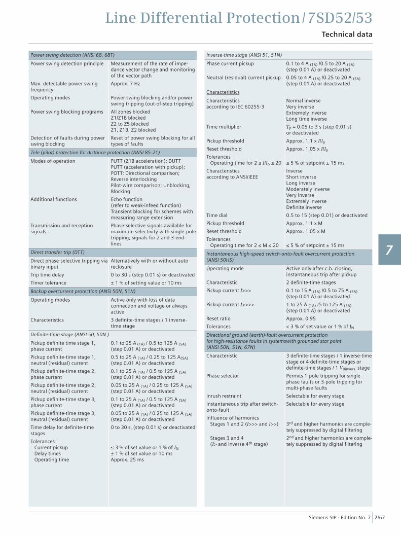
Line Differential Protection / 7SD52/53Technical data
7/67Siemens SIP · Edition No. 7
Power swing detection (ANSI 68, 68T)
Power swing detection principle
Max. detectable power swing frequency
Operating modes
Power swing blocking programs
Detection of faults during power swing blocking
Measurement of the rate of impe-dance vector change and monitoring of the vector path
Approx. 7 Hz
Power swing blocking and/or power swing tripping (out-of-step tripping)
All zones blockedZ1/Z1B blockedZ2 to Z5 blockedZ1, Z1B, Z2 blocked
Reset of power swing blocking for all types of faults
Tele (pilot) protection for distance protection (ANSI 85-21)
Modes of operation
Additional functions
Transmission and reception signals
PUTT (Z1B acceleration); DUTTPUTT (acceleration with pickup); POTT; Directional comparison; Reverse interlocking Pilot-wire comparison; Unblocking; Blocking
Echo function (refer to weak-infeed function)Transient blocking for schemes with measuring range extension
Phase-selective signals available for maximum selectivity with single-pole tripping; signals for 2 and 3-end- lines
Direct transfer trip (DTT)
Direct phase-selective tripping via binary input
Trip time delay
Timer tolerance
Alternatively with or without auto-reclosure
0 to 30 s (step 0.01 s) or deactivated
± 1 % of setting value or 10 ms
Backup overcurrent protection (ANSI 50N, 51N)
Operating modes
Characteristics
Active only with loss of data connection and voltage or always active
3 defi nite-time stages / 1 inverse-time stage
Defi nite-time stage (ANSI 50, 50N )
Pickup defi nite time stage 1, phase current
Pickup defi nite-time stage 1,neutral (residual) current
Pickup defi nite-time stage 2,phase current
Pickup defi nite-time stage 2, neutral (residual) current
Pickup defi nite-time stage 3,phase current
Pickup defi nite-time stage 3, neutral (residual) current
Time delay for defi nite-time stages
Tolerances Current pickup Delay times Operating time
0.1 to 25 A (1A) / 0.5 to 125 A (5A)(step 0.01 A) or deactivated
0.5 to 25 A (1A) / 0.25 to 125 A(5A)(step 0.01 A) or deactivated
0.1 to 25 A (1A) / 0.5 to 125 A (5A)(step 0.01 A) or deactivated
0.05 to 25 A (1A) / 0.25 to 125 A (5A)(step 0.01 A) or deactivated
0.1 to 25 A (1A) / 0.5 to 125 A (5A)(step 0.01 A) or deactivated
0.05 to 25 A (1A) / 0.25 to 125 A (5A)(step 0.01 A) or deactivated
0 to 30 s, (step 0.01 s) or deactivated
≤ 3 % of set value or 1 % of IN± 1 % of set value or 10 msApprox. 25 ms
Inverse-time stage (ANSI 51, 51N)
Phase current pickup
Neutral (residual) current pickup
0.1 to 4 A (1A) /0.5 to 20 A (5A)(step 0.01 A) or deactivated
0.05 to 4 A (1A) /0.25 to 20 A (5A)(step 0.01 A) or deactivated
Characteristics
Characteristics according to IEC 60255-3
Time multiplier
Pickup threshold
Reset threshold
Tolerances Operating time for 2 ≤ I/Ip ≤ 20
Characteristics according to ANSI/IEEE
Time dial
Pickup threshold
Reset threshold
Tolerances Operating time for 2 ≤ M ≤ 20
Normal inverseVery inverseExtremely inverseLong time inverse
Tp = 0.05 to 3 s (step 0.01 s) or deactivated
Approx. 1.1 x I/Ip
Approx. 1.05 x I/Ip
≤ 5 % of setpoint ± 15 ms
InverseShort inverseLong inverseModerately inverseVery inverseExtremely inverseDefi nite inverse
0.5 to 15 (step 0.01) or deactivated
Approx. 1.1 x M
Approx. 1.05 x M
≤ 5 % of setpoint ± 15 ms
Instantaneous high-speed switch-onto-fault overcurrent protection(ANSI 50HS)
Operating mode
Characteristic
Pickup current I>>>
Pickup current I>>>>
Reset ratio
Tolerances
Active only after c.b. closing; instantaneous trip after pickup
2 defi nite-time stages
0.1 to 15 A (1A) /0.5 to 75 A (5A)(step 0.01 A) or deactivated
1 to 25 A (1A) /5 to 125 A (5A)(step 0.01 A) or deactivated
Approx. 0.95
< 3 % of set value or 1 % of IN
Directional ground (earth)-fault overcurrent protectionfor high-resistance faults in systemswith grounded star point(ANSI 50N, 51N, 67N)
Characteristic
Phase selector
Inrush restraint
Instantaneous trip after switch-onto-fault
Infl uence of harmonics Stages 1 and 2 (I>>> and I>>)
Stages 3 and 4 (I> and inverse 4th stage)
3 defi nite-time stages / 1 inverse-time stage or 4 defi nite-time stages or defi nite-time stages / 1 V0invers. stage
Permits 1-pole tripping for single-phase faults or 3-pole tripping for multi-phase faults
Selectable for every stage
Selectable for every stage
3rd and higher harmonics are comple-tely suppressed by digital fi ltering
2nd and higher harmonics are comple-tely suppressed by digital fi ltering
1
2
3
4
5
6
7
8
9
10
11
12
13
14
15
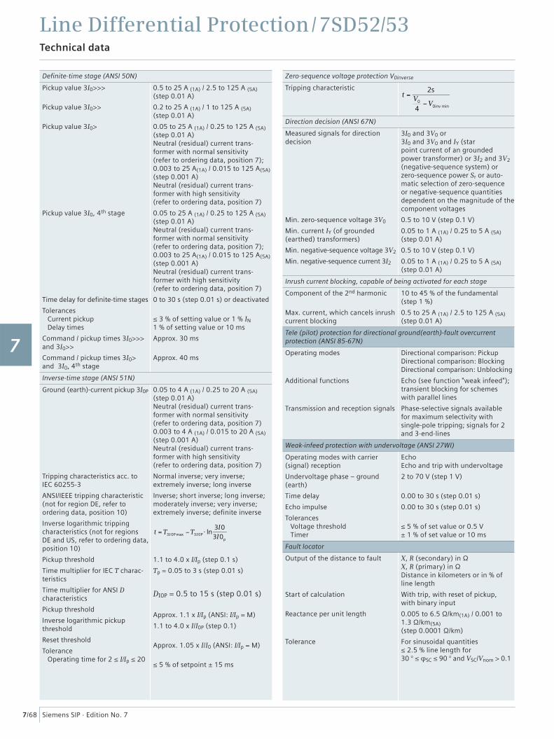
Line Differential Protection / 7SD52/53Technical data
7/68 Siemens SIP · Edition No. 7
Defi nite-time stage (ANSI 50N)
Pickup value 3I0>>>
Pickup value 3I0>>
Pickup value 3I0>
Pickup value 3I0, 4th stage
Time delay for defi nite-time stages
Tolerances Current pickup Delay times
Command / pickup times 3I0>>> and 3I0>>
Command / pickup times 3I0> and 3I0, 4th stage
0.5 to 25 A (1A) / 2.5 to 125 A (5A) (step 0.01 A)
0.2 to 25 A (1A) / 1 to 125 A (5A) (step 0.01 A)
0.05 to 25 A (1A) / 0.25 to 125 A (5A)(step 0.01 A)Neutral (residual) current trans-former with normal sensitivity (refer to ordering data, position 7);0.003 to 25 A(1A) / 0.015 to 125 A(5A)(step 0.001 A)Neutral (residual) current trans-former with high sensitivity (refer to ordering data, position 7)
0.05 to 25 A (1A) / 0.25 to 125 A (5A) (step 0.01 A)Neutral (residual) current trans-former with normal sensitivity (refer to ordering data, position 7);0.003 to 25 A(1A) / 0.015 to 125 A(5A) (step 0.001 A)Neutral (residual) current trans-former with high sensitivity (refer to ordering data, position 7)
0 to 30 s (step 0.01 s) or deactivated
≤ 3 % of setting value or 1 % IN 1 % of setting value or 10 ms
Approx. 30 ms
Approx. 40 ms
Inverse-time stage (ANSI 51N)
Ground (earth)-current pickup 3I0P
Tripping characteristics acc. to IEC 60255-3
ANSI/IEEE tripping characteristic(not for region DE, refer to ordering data, position 10)
Inverse logarithmic tripping characteristics (not for regions DE and US, refer to ordering data, position 10)
Pickup threshold
Time multiplier for IEC T charac-teristics
Time multiplier for ANSI D characteristics
Pickup threshold
Inverse logarithmic pickup threshold
Reset threshold
Tolerance Operating time for 2 ≤ I/Ip ≤ 20
0.05 to 4 A (1A) / 0.25 to 20 A (5A) (step 0.01 A)Neutral (residual) current trans-former with normal sensitivity (refer to ordering data, position 7)0.003 to 4 A (1A) / 0.015 to 20 A (5A) (step 0.001 A)Neutral (residual) current trans-former with high sensitivity (refer to ordering data, position 7)
Normal inverse; very inverse; extremely inverse; long inverse
Inverse; short inverse; long inverse; moderately inverse; very inverse; extremely inverse; defi nite inverse
t = T3I 0P max −T3I 0P ⋅ ln
3I03I0p
1.1 to 4.0 x I/Ip (step 0.1 s)
Tp = 0.05 to 3 s (step 0.01 s)
DI0P = 0.5 to 15 s (step 0.01 s)
Approx. 1.1 x I/Ip (ANSI: I/Ip = M)
1.1 to 4.0 x I/I0P (step 0.1)
Approx. 1.05 x I/I0 (ANSI: I/Ip = M)
≤ 5 % of setpoint ± 15 ms
Zero-sequence voltage protection V0inverse
Tripping characteristic
t =2s
V0
4−V0inv min
Direction decision (ANSI 67N)
Measured signals for direction decision
Min. zero-sequence voltage 3V0
Min. current IY (of grounded (earthed) transformers)
Min. negative-sequence voltage 3V2
Min. negative-sequence current 3I2
3I0 and 3V0 or3I0 and 3V0 and IY (star point current of an grounded power transformer) or 3I2 and 3V2 (negative-sequence system) or zero-sequence power Sr or auto-matic selection of zero-sequence or negative-sequence quantities dependent on the magnitude of the component voltages
0.5 to 10 V (step 0.1 V)
0.05 to 1 A (1A) / 0.25 to 5 A (5A) (step 0.01 A)
0.5 to 10 V (step 0.1 V)
0.05 to 1 A (1A) / 0.25 to 5 A (5A) (step 0.01 A)
Inrush current blocking, capable of being activated for each stage
Component of the 2nd harmonic
Max. current, which cancels inrush current blocking
10 to 45 % of the fundamental (step 1 %)
0.5 to 25 A (1A) / 2.5 to 125 A (5A) (step 0.01 A)
Tele (pilot) protection for directional ground(earth)-fault overcurrentprotection (ANSI 85-67N)
Operating modes
Additional functions
Transmission and reception signals
Directional comparison: PickupDirectional comparison: BlockingDirectional comparison: Unblocking
Echo (see function "weak infeed");transient blocking for schemes with parallel lines
Phase-selective signals available for maximum selectivity with single-pole tripping; signals for 2 and 3-end-lines
Weak-infeed protection with undervoltage (ANSI 27WI)
Operating modes with carrier (signal) reception
Undervoltage phase – ground (earth)
Time delay
Echo impulse
Tolerances Voltage threshold Timer
EchoEcho and trip with undervoltage
2 to 70 V (step 1 V)
0.00 to 30 s (step 0.01 s)
0.00 to 30 s (step 0.01 s)
≤ 5 % of set value or 0.5 V ± 1 % of set value or 10 ms
Fault locator
Output of the distance to fault
Start of calculation
Reactance per unit length
Tolerance
X, R (secondary) in ΩX, R (primary) in ΩDistance in kilometers or in % of line length
With trip, with reset of pickup, with binary input
0.005 to 6.5 Ω/km(1A) / 0.001 to 1.3 Ω/km(5A)(step 0.0001 Ω/km)
For sinusoidal quantities ≤ 2.5 % line length for30 ° ≤ φSC ≤ 90 ° and VSC/Vnom > 0.1
1
2
3
4
5
6
7
8
9
10
11
12
13
14
15
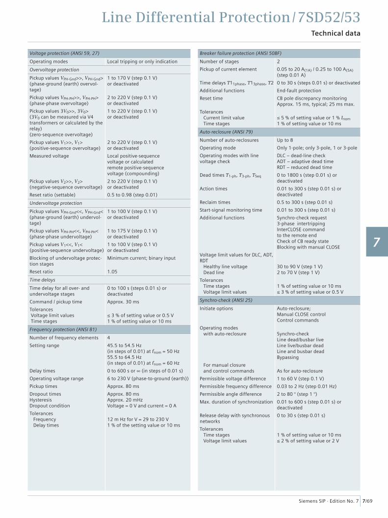
Line Differential Protection / 7SD52/53Technical data
7/69Siemens SIP · Edition No. 7
Voltage protection (ANSI 59, 27)
Operating modes Local tripping or only indication
Overvoltage protection
Pickup values VPH-Gnd>>, VPH-Gnd>(phase-ground (earth) overvol-tage)
Pickup values VPH-PH>>, VPH-PH>(phase-phase overvoltage)
Pickup values 3V0>>, 3V0>(3V0 can be measured via V4 transformers or calculated by the relay)(zero-sequence overvoltage)
Pickup values V1>>, V1> (positive-sequence overvoltage)
Measured voltage
Pickup values V2>>, V2> (negative-sequence overvoltage)
Reset ratio (settable)
1 to 170 V (step 0.1 V)or deactivated
2 to 220 V (step 0.1 V)or deactivated
1 to 220 V (step 0.1 V)or deactivated
2 to 220 V (step 0.1 V)or deactivated
Local positive-sequencevoltage or calculatedremote positive-sequencevoltage (compounding)
2 to 220 V (step 0.1 V)or deactivated
0.5 to 0.98 (step 0.01)
Undervoltage protection
Pickup values VPH-Gnd<<, VPH-Gnd<(phase-ground (earth) undervol-tage)
Pickup values VPH-PH<<, VPH-PH<(phase-phase undervoltage)
Pickup values V1<<, V1< (positive-sequence undervoltage)
Blocking of undervoltage protec-tion stages
Reset ratio
1 to 100 V (step 0.1 V)or deactivated
1 to 175 V (step 0.1 V)or deactivated
1 to 100 V (step 0.1 V)or deactivated
Minimum current; binary input
1.05
Time delays
Time delay for all over- and undervoltage stages
Command / pickup time
Tolerances Voltage limit values Time stages
0 to 100 s (steps 0.01 s) or deactivated
Approx. 30 ms
≤ 3 % of setting value or 0.5 V1 % of setting value or 10 ms
Frequency protection (ANSI 81)
Number of frequency elements
Setting range
Delay times
Operating voltage range
Pickup times
Dropout timesHysteresisDropout condition
Tolerances Frequency Delay times
4
45.5 to 54.5 Hz(in steps of 0.01) at fnom = 50 Hz55.5 to 64.5 Hz(in steps of 0.01) at fnom = 60 Hz
0 to 600 s or ∞ (in steps of 0.01 s)
6 to 230 V (phase-to-ground (earth))
Approx. 80 ms
Approx. 80 msApprox. 20 mHzVoltage = 0 V and current = 0 A
12 m Hz for V = 29 to 230 V1 % of the setting value or 10 ms
Breaker failure protection (ANSI 50BF)
Number of stages
Pickup of current element
Time delays T11phase, T13phase, T2
Additional functions
Reset time
Tolerances Current limit value Time stages
2
0.05 to 20 A(1A) / 0.25 to 100 A(5A) (step 0.01 A)
0 to 30 s (steps 0.01 s) or deactivated
End-fault protection
CB pole discrepancy monitoringApprox. 15 ms, typical; 25 ms max.
≤ 5 % of setting value or 1 % Inom 1 % of setting value or 10 ms
Auto-reclosure (ANSI 79)
Number of auto-reclosures
Operating mode
Operating modes with line voltage check
Dead times T1-ph, T3-ph, TSeq
Action times
Reclaim times
Start-signal monitoring time
Additional functions
Voltage limit values for DLC, ADT, RDT Healthy line voltage Dead line
Tolerances Time stages Voltage limit values
Up to 8
Only 1-pole; only 3-pole, 1 or 3-pole
DLC – dead-line checkADT – adaptive dead timeRDT – reduced dead time
0 to 1800 s (step 0.01 s) or deactivated
0.01 to 300 s (step 0.01 s) or deactivated
0.5 to 300 s (step 0.01 s)
0.01 to 300 s (step 0.01 s)
Synchro-check request3-phase intertrippingInterCLOSE command to the remote end Check of CB ready stateBlocking with manual CLOSE
30 to 90 V (step 1 V)2 to 70 V (step 1 V)
1 % of setting value or 10 ms≤ 3 % of setting value or 0.5 V
Synchro-check (ANSI 25)
Initiate options
Operating modes with auto-reclosure
For manual closure and control commands
Permissible voltage difference
Permissible frequency difference
Permissible angle difference
Max. duration of synchronization
Release delay with synchronous networks
Tolerances Time stages Voltage limit values
Auto-reclosure;Manual CLOSE controlControl commands
Synchro-checkLine dead/busbar liveLine live/busbar deadLine and busbar deadBypassing
As for auto-reclosure
1 to 60 V (step 0.1 V)
0.03 to 2 Hz (step 0.01 Hz)
2 to 80 ° (step 1 °)
0.01 to 600 s (step 0.01 s) or deactivated
0 to 30 s (step 0.01 s)
1 % of setting value or 10 ms≤ 2 % of setting value or 2 V
1
2
3
4
5
6
7
8
9
10
11
12
13
14
15
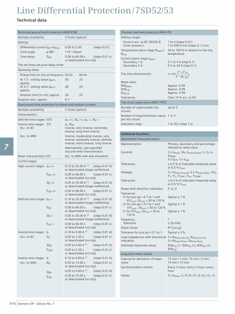
Line Differential Protection / 7SD52/53Technical data
7/70 Siemens SIP · Edition No. 7
Restricted ground-fault protection (ANSI 87N)
Multiple availability 2 times (option)
Settings
Differential current IREF>/INobj
Limit angle φ REF
Time delay TREF
The set times are pure delay times
0.05 to 2.00 (steps 0.01)
110 ° (fi xed)
0.00 to 60.00 s (steps 0.01 s)or deactivated (no trip)
Operating times
Pickup time (in ms) at frequency
At 1.5 · setting value IREF>, approx. At 2.5 · setting value IREF>, approx.
Dropout time (in ms), approx.
Dropout ratio, approx.
50 Hz 60 Hz
30 25
28 24
26 23
0.7
Overcurrent-time protection for phase and residual currents
Multiple availability 3 times (option)
Characteristics
Defi nite-time stages (DT)
Inverse-time stages (IT) Acc. to IEC
Acc. to ANSI
Reset characteristics (IT)
IPh >>, 3I0 >>, IPh >, 3I0 >
IP, 3I0PInverse, very inverse, extremely inverse, long-time inverse
Inverse, moderately inverse, very inverse, extremely inverse, defi nite inverse, short inverse, long inverse
Alternatively, user-specifi edtrip and reset characteristics
Acc. to ANSI with disk emulation
Current stages
High-current stages IPh >>
TIPh >>
3I0 >>
T3I0 >>
Defi nite-time stages IPh >
TIPh
3I0 >
T3I0 >
Inverse-time stages IP
Acc. to IEC TIP
3I0P
T3I0P
Inverse-time stages IP
Acc. to ANSI DIP
3I0P
D3I0
0.10 to 35.00 A 1) (steps 0.01 A)or deactivated (stage ineffective)
0.00 to 60.00 s (steps 0.01 s)or deactivated (no trip)
0.05 to 35.00 A 1) (steps 0.01 A)or deactivated (stage ineffective)
0.00 to 60.00 s (steps 0.01 s)or deactivated (no trip)
0.10 to 35.00 A 1) (steps 0.01 A)or deactivated (stage ineffective)
0.00 to 60.00 s (steps 0.01 s)or deactivated (no trip)
0.05 to 35.00 A 1) (steps 0.01 A)or deactivated (stage ineffective)
0.00 to 60.00 s (steps 0.01 s)or deactivated (no trip)
0.10 to 4.00 A 1) (steps 0.01 A)
0.05 to 3.20 s (steps 0.01 s)or deactivated (no trip)
0.05 to 4.00 A 1) (steps 0.01 A)
0.05 to 3.20 s (steps 0.01 s)or deactivated (no trip)
0.10 to 4.00 A 1) (steps 0.01 A)
0.50 to 15.00 s (steps 0.01 s)or deactivated (no trip)
0.05 to 4.00 A 1) (steps 0.01 A)
0.50 to 15.00 s (steps 0.01 s)or deactivated (no trip)
Thermal overload protection (ANSI 49)
Setting ranges
Factor k acc. to IEC 60255-8 Time constant τ
Temperature alarm stage Θalarm/Θtrip
Current alarm stage Ialarm Secondary 1 A Secondary 5 A
Trip time characteristic
Reset ratiosΘ/Θalarm Θ/Θtrip I/Ialarm
Tolerances
1 to 4 (steps 0.01)1 to 999.9 min (steps 0.1 min)
50 to 100 % in relation to the trip temperature
0.1 to 4 A (step 0.1)0.5 to 20 A (step 0.1)
t = τ lnI 2 − I 2
pre
I 2 − k⋅ IN( )2
Approx. 0.99Approx. 0.99Approx. 0.99
Class 10 % acc. to IEC
Trip circuit supervision (ANSI 74TC)
Number of supervisable trip circuits
Number of required binary inputs per trip circuit
Indication relay
Up to 3
1 or 2
1 to 30 s (step 1 s)
Additional functions
Operational measured values
Representation
Currents
Tolerances
Voltages
Tolerances
Power with direction indication
Tolerances P: for |cos φ| = 0.7 to 1 and
V/Vnom, I/Inom = 50 to 120 % Q: for |sin φ| = 0.7 to 1 and
V/Vnom , I/Inom = 50 to 120 % S: for V/Vnom, I/Inom = 50 to
120 %
Frequency Tolerance
Power factor
Tolerance for |cos φ| = 0.7 to 1
Load impedances with directional indication
Overload measured values
Primary, secondary and percentage referred to rated value
3 x IPhase; 3I0; IGnd sensitve; I1; I2; IY; 3I0PAR 3 x IDiff, 3 x IStab
≤ 0.5 % of indicated measured value or 0.5 % Inom
3 x VPhase-Ground; 3 x VPhase-Phase; 3V0, V1, V2, VSYNC, Ven, VCOMP
≤ 0.5 % of indicated measured value or 0.5 % Vnom
P, Q, S
Typical ≤ 1 %
Typical ≤ 1 %
Typical ≤ 1 %
f≤ 20 mHz
PF (cos φ)
Typical ≤ 3 %
3 x RPhase-Ground, XPhase-Ground3 x RPhase-Phase, XPhase-Phase
Θ/ΘTrip L1; Θ/ΘTrip L2; Θ/ΘTrip L3;Θ/ΘTrip
Long-term mean values
Interval for derivation of mean value
Synchronization instant
Values
15 min / 1 min; 15 min / 3 min; 15 min / 15 min
Every ¼ hour; every ½ hour; every hour
3 x IPhase; I1; P; P+; P-; Q; Q+; Q–; S
1
2
3
4
5
6
7
8
9
10
11
12
13
14
15
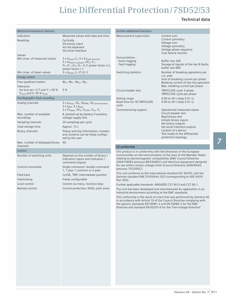
Line Differential Protection / 7SD52/53Technical data
7/71Siemens SIP · Edition No. 7
Minimum /maximum memory
Indication
Resetting
ValuesMin./max. of measured values
Min./max. of mean values
Measured values with date and time
CyclicallyVia binary inputVia the keyboardVia serial interface
3 x IPhase; I1; 3 x VPhase-Ground; 3 x VPhase-to-phase; 3V0; V1;P+; P–; Q+; Q–; S; f; power factor (+); power factor (–)3 x IPhase; I1; P; Q; S
Energy meters
Four-quadrant meters
Tolerance for |cos φ| > 0.7 and V > 50 % Vnom and I> 50 % Inom
WP+; WP–; WQ+; WQ–
5 %
Oscillographic fault recording
Analog channels
Max. number of available recordings
Sampling intervals
Total storage time
Binary channels
Max. number of displayed binary channels
3 x IPhase, 3I0, 3I0PAR, 3I0 Gnd sensitive, 3 x IDiff, 3 x IStab 3 x VPhase, 3V0, VSYNC, Ven, Vx
8, backed-up by battery if auxiliary voltage supply fails
20 samplings per cycle
Approx. 15 s
Pickup and trip information; number and contents can be freely confi gu-red by the user
40
Control
Number of switching units
Control commands
Feed back
Interlocking
Local control
Remote control
Depends on the number of binary / indication inputs and indication / command outputs
Single command / double command 1, 1 plus 1 common or 2 pole
CLOSE, TRIP, intermediate position
Freely confi gurable
Control via menu, function keys
Control protection, DIGSI, pilot wires
Further additional functions
Measurement supervision
Annunciations Event logging Fault logging
Switching statistics
Circuit-breaker test
Setting rangeDead time for CB TRIP/CLOSEcycle
Commissioning support
Current sumCurrent symmetryVoltage sumVoltage symmetryVoltage phase sequenceFuse failure monitor
Buffer size 200Storage of signals of the last 8 faults,buffer size 800
Number of breaking operations per c.b. poleSum of breaking current per phase Breaking current of last trip operationMax. breaking current per phase
TRIP/CLOSE cycle 3-phaseTRIP/CLOSE cycle per phase
0.00 to 30 s (step 0.01 s)0.00 to 30 s (step 0.01 s)
Operational measured valuesCircuit-breaker testRead binary testInitiate binary inputsSet binary outputsSet serial interface outputsLockout of a deviceTest mode ot the differentialprotection topology
CE conformity
This product is in conformity with the Directives of the European Communities on the harmonization of the laws of the Member States relating to electromagnetic compatibility (EMC Council Directive 2004/108/EG previous 89/336/EEC) and electrical equipment designed for use within certain voltage limits (Council Directive 2006/95/EG previous 73/23/EEC).
This unit conforms to the international standard IEC 60255, and the German standard DIN 57435/Part 303 (corresponding to VDE 0435/Part 303).
Further applicable standards: ANSI/IEEE C37.90.0 and C37.90.1.
The unit has been developed and manufactured for application in an industrial environment according to the EMC standards.
This conformity is the result of a test that was performed by Siemens AG in accordance with Article 10 of the Council Directive complying with the generic standards EN 50081-2 and EN 50082-2 for the EMC Directive and standard EN 60255-6 for the “low-voltage Directive”.
1
2
3
4
5
6
7
8
9
10
11
12
13
14
15
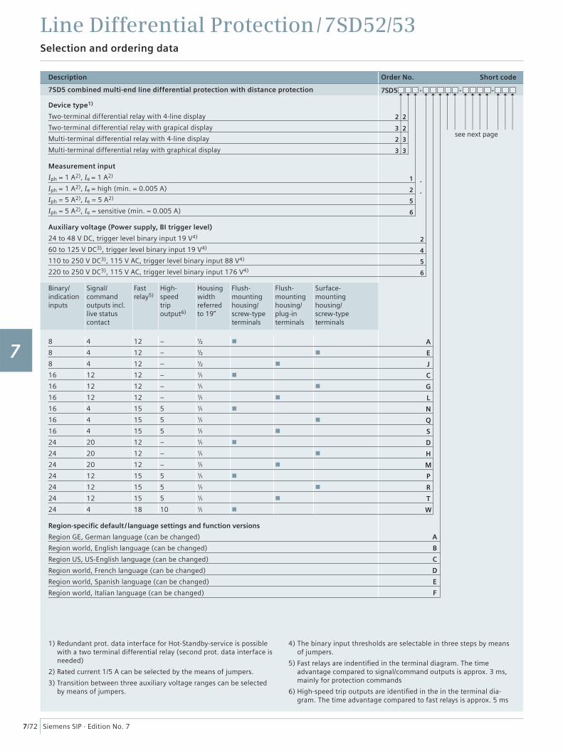
Line Differential Protection / 7SD52/53Selection and ordering data
7/72 Siemens SIP · Edition No. 7
Description Order No. Short code
7SD5 combined multi-end line differential protection with distance protection 7SD5 - - -
Device type1)
Two-terminal differential relay with 4-line display
Two-terminal differential relay with grapical display
Multi-terminal differential relay with 4-line display
Multi-terminal differential relay with graphical display
Measurement input
Iph = 1 A2), Ie = 1 A2)
Iph = 1 A2), Ie = high (min. = 0.005 A)
Iph = 5 A2), Ie = 5 A2)
Iph = 5 A2), Ie = sensitive (min. = 0.005 A)
Auxiliary voltage (Power supply, BI trigger level)
24 to 48 V DC, trigger level binary input 19 V4)
60 to 125 V DC3), trigger level binary input 19 V4)
110 to 250 V DC3), 115 V AC, trigger level binary input 88 V4)
220 to 250 V DC3), 115 V AC, trigger level binary input 176 V4)
Binary/indication inputs
Signal/ command outputs incl. live status contact
Fast relay5)
High-speed trip output6)
Housing width referred to 19”
Flush-mounting housing/screw-type terminals
Flush-mounting housing/plug-in terminals
Surface-mounting housing/screw-type terminals
8
8
8
16
16
16
16
16
16
24
24
24
24
24
24
24
4
4
4
12
12
12
4
4
4
20
20
20
12
12
12
4
12
12
12
12
12
12
15
15
15
12
12
12
15
15
15
18
–
–
–
–
–
–
5
5
5
–
–
–
5
5
5
10
½
½
½
�
�
�
�
�
�
�
�
�
�
�
�
�
Region-specifi c default / language settings and function versions
Region GE, German language (can be changed)
Region world, English language (can be changed)
Region US, US-English language (can be changed)
Region world, French language (can be changed)
Region world, Spanish language (can be changed)
Region world, Italian language (can be changed)
2 2
3 2
2 3
3 3
1
2
2
4
5
5
A
E
J
C
G
L
N
Q
S
D
H
M
P
R
T
W
A
B
C
D
E
F
6
6
see next page
1) Redundant prot. data interface for Hot-Standby-service is possible with a two terminal differential relay (second prot. data interface is needed)
2) Rated current 1/5 A can be selected by the means of jumpers.
3) Transition between three auxiliary voltage ranges can be selected by means of jumpers.
4) The binary input thresholds are selectable in three steps by means of jumpers.
5) Fast relays are indentifi ed in the terminal diagram. The time advantage compared to signal/command outputs is approx. 3 ms, mainly for protection commands
6) High-speed trip outputs are identifi ed in the in the terminal dia-gram. The time advantage compared to fast relays is approx. 5 ms
1
2
3
4
5
6
7
8
9
10
11
12
13
14
15
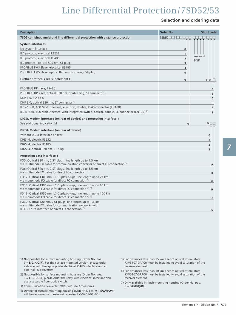
Line Differential Protection / 7SD52/53Selection and ordering data
7/73Siemens SIP · Edition No. 7
Description Order No. Short code
7SD5 combined multi-end line differential protection with distance protection 7SD52 - - -
System interfaces
No system interface
IEC protocol, electrical RS232
IEC protocol, electrical RS485
IEC protocol, optical 820 nm, ST-plug
PROFIBUS FMS Slave, electrical RS485
PROFIBUS FMS Slave, optical 820 nm, twin-ring, ST-plug
Further protocols see supplement L
PROFIBUS DP slave, RS485
PROFIBUS DP slave, optical 820 nm, double ring, ST connector 1)
DNP 3.0, RS485 G
DNP 3.0, optical 820 nm, ST connector 1)
IEC 61850, 100 Mbit Etherrnet, electrical, double, RS45 connector (EN100)
IEC 61850, 100 Mbit Ethernet, with integrated switch, optical, double, LC-connector (EN100) 2)
DIGSI / Modem interface (on rear of device) and protection interface 1
See additional indication M
DIGSI / Modem interface (on rear of device)
Without DIGSI-interface on rear
DIGSI 4, electric RS232
DIGSI 4, electric RS485
DIGSI 4, optical 820 nm, ST plug
Protection data interface 1
FO5: Optical 820 nm, 2 ST-plugs, line length up to 1.5 kmvia multimode FO cable for communication converter or direct FO connection 3)
FO6: Optical 820 nm, 2 ST-plugs, line length up to 3.5 kmvia multimode FO cable for direct FO connection
FO17: Optical 1300 nm, LC-Duplex-plugs, line length up to 24 kmvia monomode FO cable for direct FO connection 4)
FO18: Optical 1300 nm, LC-Duplex-plugs, line length up to 60 kmvia monomode FO cable for direct FO connection 4) 5)
FO19: Optical 1550 nm, LC-Duplex-plugs, line length up to 100 kmvia monomode FO cable for direct FO connection 4) 6)
FO30: Optical 820 nm, 2 ST-plugs, line length up to 1.5 kmvia multimode FO cable for communication networks withIEEE C37.94 interface or direct FO connection 7)
1
B
1
H
0
L 0
M
A
0
6
2
G
2
9
A
B
G
H
R
S
9
S
3
3
J
4
1) Not possible for surface mounting housing (Order No. pos. 9 = E/G/H/Q/R). For the surface mounted version, please order a device with the appropriate electrical RS485 interface and an external FO-converter
2) Not possible for surface mounting housing (Order No. pos. 9 = E/G/H/Q/R) please order the relay with electrical interface and use a separate fi ber-optic switch.
3) Communication converter 7XV5662, see Accessories.
4) Device for surface mounting housing (Order No. pos. 9 = E/G/H/Q/R) will be delivered with external repeater 7XV5461-0Bx00.
5) For distances less than 25 km a set of optical attenuators 7XV5107-0AA00 must be installed to avoid saturation of the receiver element
6) For distances less than 50 km a set of optical attenuators 7XV5107-0AA00 must be installed to avoid saturation of the receiver element
7) Only available in fl ush-mounting housing (Order No. pos. 9 ≠ E/G/H/Q/R).
see next page
1
2
3
4
5
6
7
8
9
10
11
12
13
14
15
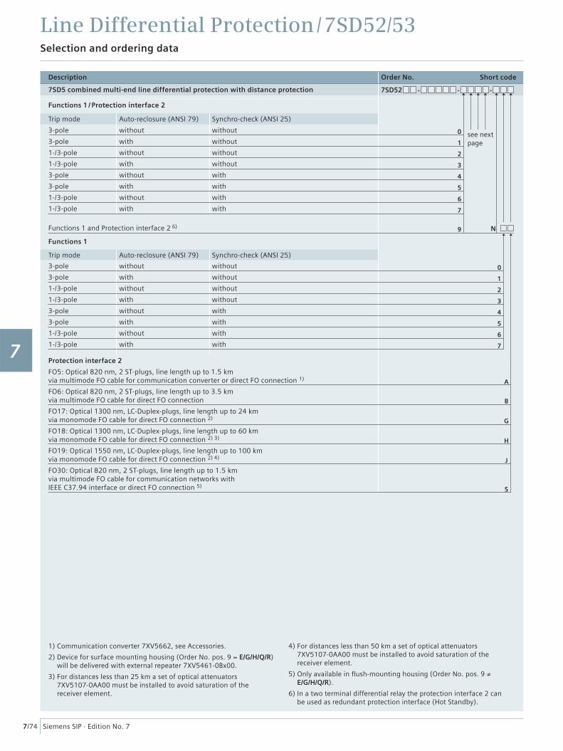
Description Order No. Short code
7SD5 combined multi-end line differential protection with distance protection 7SD52 - - -
Functions 1 / Protection interface 2
Trip mode Auto-reclosure (ANSI 79) Synchro-check (ANSI 25)
3-pole
3-pole
1-/3-pole
1-/3-pole
3-pole
3-pole
1-/3-pole
1-/3-pole
without
with
without
with
without
with
without
with
without
without
without
without
with
with
with
with
Functions 1 and Protection interface 2 6)
Functions 1
Trip mode Auto-reclosure (ANSI 79) Synchro-check (ANSI 25)
3-pole
3-pole
1-/3-pole
1-/3-pole
3-pole
3-pole
1-/3-pole
1-/3-pole
without
with
without
with
without
with
without
with
without
without
without
without
with
with
with
with
Protection interface 2
FO5: Optical 820 nm, 2 ST-plugs, line length up to 1.5 kmvia multimode FO cable for communication converter or direct FO connection 1)
FO6: Optical 820 nm, 2 ST-plugs, line length up to 3.5 kmvia multimode FO cable for direct FO connection
FO17: Optical 1300 nm, LC-Duplex-plugs, line length up to 24 kmvia monomode FO cable for direct FO connection 2)
FO18: Optical 1300 nm, LC-Duplex-plugs, line length up to 60 kmvia monomode FO cable for direct FO connection 2) 3)
FO19: Optical 1550 nm, LC-Duplex-plugs, line length up to 100 kmvia monomode FO cable for direct FO connection 2) 4)
FO30: Optical 820 nm, 2 ST-plugs, line length up to 1.5 kmvia multimode FO cable for communication networks withIEEE C37.94 interface or direct FO connection 5)
1
B
A
5
1
H
0
N
4
0
5
2
G
6
2
6
7
9
S
3
7
3
J
4
1) Communication converter 7XV5662, see Accessories.
2) Device for surface mounting housing (Order No. pos. 9 = E/G/H/Q/R) will be delivered with external repeater 7XV5461-0Bx00.
3) For distances less than 25 km a set of optical attenuators 7XV5107-0AA00 must be installed to avoid saturation of the receiver element.
4) For distances less than 50 km a set of optical attenuators 7XV5107-0AA00 must be installed to avoid saturation of the receiver element.
5) Only available in fl ush-mounting housing (Order No. pos. 9 ≠ E/G/H/Q/R).
6) In a two terminal differential relay the protection interface 2 canbe used as redundant protection interface (Hot Standby).
Line Differential Protection / 7SD52/53Selection and ordering data
7/74 Siemens SIP · Edition No. 7
see next page
1
2
3
4
5
6
7
8
9
10
11
12
13
14
15
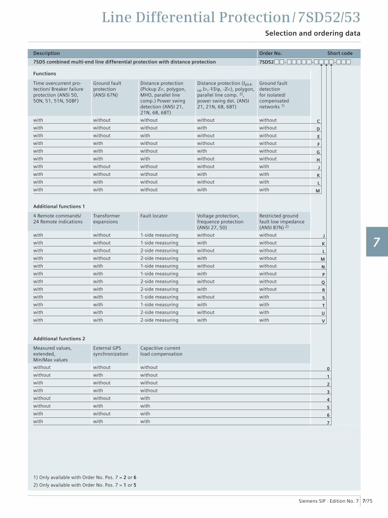
Line Differential Protection / 7SD52/53Selection and ordering data
7/75Siemens SIP · Edition No. 7
Description Order No. Short code
7SD5 combined multi-end line differential protection with distance protection 7SD52 - - -
Functions
Time overcurrent pro-tection/ Breaker failure protection (ANSI 50, 50N, 51, 51N, 50BF)
Ground fault protection (ANSI 67N)
Distance protection (Pickup Z<, polygon, MHO, parallel line comp.) Power swing detection (ANSI 21, 21N, 68, 68T)
Distance protection (Ipick-
up I>,-VI/φ, -Z<), polygon, parallel line comp. 2), power swing det. (ANSI 21, 21N, 68, 68T)
Ground fault detection for isolated/compensated networks 1)
with
with
with
with
with
with
with
with
with
with
without
without
without
with
with
with
without
without
with
with
without
without
with
without
without
with
without
without
without
without
without
with
without
without
with
without
without
with
without
with
without
without
without
without
without
without
with
with
with
with
Additional functions 1
4 Remote commands/24 Remote indications
Transformer expansions
Fault locator Voltage protection, frequence protection (ANSI 27, 50)
Restricted ground fault low impedance (ANSI 87N) 2)
with
with
with
with
with
with
with
with
with
with
with
with
without
without
without
without
with
with
with
with
with
with
with
with
1-side measuring
1-side measuring
2-side measuring
2-side measuring
1-side measuring
1-side measuring
2-side measuring
2-side measuring
1-side measuring
1-side measuring
2-side measuring
2-side measuring
without
with
without
with
without
with
without
with
without
with
without
with
without
without
without
without
without
without
without
without
with
with
with
with
Additional functions 2
Measured values, extended, Min/Max values
External GPS synchronization
Capacitive current load compensation
without
without
with
with
without
without
with
with
without
with
without
with
without
with
without
with
without
without
without
without
with
with
with
with
0
1
2
3
4
5
6
7
J
K
L
M
N
P
Q
R
S
T
U
V
C
D
E
F
G
H
J
K
L
M
1) Only available with Order No. Pos. 7 = 2 or 6
2) Only available with Order No. Pos. 7 = 1 or 5
1
2
3
4
5
6
7
8
9
10
11
12
13
14
15
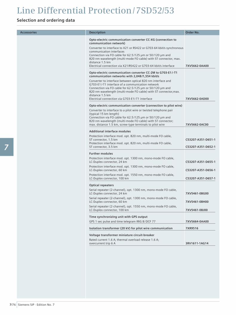
Accessories
Line Differential Protection / 7SD52/53Selection and ordering data
7/76 Siemens SIP · Edition No. 7
Description Order No.
Opto-electric communication converter CC-XG (connection to communication network)
Converter to interface to X21 or RS422 or G703-64 kbit/s synchronous communication interfacesConnection via FO cable for 62.5 /125 μm or 50 /120 μm and 820 nm wavelength (multi-mode FO cable) with ST connector, max. distance 1.5 kmElectrical connection via X21/RS422 or G703-64 kbit/s interface 7XV5662-0AA00
Opto-electric communication converter CC-2M to G703-E1 / -T1 communication networks with 2,048 /1,554 kbit/s
Converter to interface between optical 820 nm interface and G703-E1 /-T1 interface of a communication networkConnection via FO cable for 62.5 /125 μm or 50 /120 μm and820 nm wavelength (multi-mode FO cable) with ST connector,max. distance 1.5 kmElectrical connection via G703-E1/-T1 interface 7XV5662-0AD00
Opto-electric communication converter (connection to pilot wire)
Converter to interface to a pilot wire or twisted telephone pair (typical 15 km length)Connection via FO cable for 62.5 /125 μm or 50 /120 μm and 820 nm wavelength (multi-mode FO cable) with ST connector;max. distance 1.5 km, screw-type terminals to pilot wire 7XV5662-0AC00
Additional interface modules
Protection interface mod. opt. 820 nm, multi-mode FO cable, ST connector, 1.5 kmProtection interface mod. opt. 820 nm, multi-mode FO cable, ST connector, 3.5 km
C53207-A351-D651-1
C53207-A351-D652-1
Further modules
Protection interface mod. opt. 1300 nm, mono-mode FO cable,LC-Duplex connector, 24 km
Protection interface mod. opt. 1300 nm, mono-mode FO cable,LC-Duplex connector, 60 km
Protection interface mod. opt. 1550 nm, mono-mode FO cable,LC-Duplex connector, 100 km
C53207-A351-D655-1
C53207-A351-D656-1
C53207-A351-D657-1
Optical repeaters
Serial repeater (2-channel), opt. 1300 nm, mono-mode FO cable,LC-Duplex connector, 24 km
Serial repeater (2-channel), opt. 1300 nm, mono-mode FO cable,LC-Duplex connector, 60 km
Serial repeater (2-channel), opt. 1550 nm, mono-mode FO cable,LC-Duplex connector, 100 km
7XV5461-0BG00
7XV5461-0BH00
7XV5461-0BJ00
Time synchronizing unit with GPS output
GPS 1 sec pulse and time telegram IRIG B / DCF 77 7XV5664-0AA00
Isolation transformer (20 kV) for pilot wire communication 7XR9516
Voltage transformer miniature circuit-breaker
Rated current 1.6 A; thermal overload release 1.6 A; overcurrent trip 6 A 3RV1611-1AG14
1
2
3
4
5
6
7
8
9
10
11
12
13
14
15
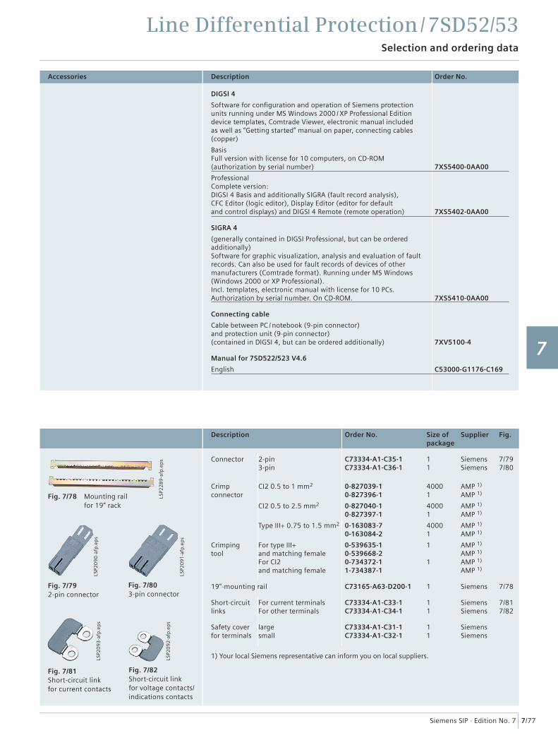
Accessories
Line Differential Protection / 7SD52/53Selection and ordering data
7/77Siemens SIP · Edition No. 7
Fig. 7/78 Mounting rail for 19" rack
Fig. 7/79 2-pin connector
Fig. 7/80 3-pin connector
Fig. 7/81 Short-circuit link for current contacts
Fig. 7/82 Short-circuit link for voltage contacts/ indications contacts
LSP2
093
-afp
.ep
s
LSP2
092
-afp
.ep
s
LSP2
09
0-a
fp.e
ps
LSP2
091
-afp
.ep
s
LSP2
28
9-a
fp.e
ps
Description Order No. Size ofpackage
Supplier Fig.
Connector 2-pin3-pin
C73334-A1-C35-1C73334-A1-C36-1
11
SiemensSiemens
7/797/80
Crimp connector
Crimping tool
CI2 0.5 to 1 mm2
CI2 0.5 to 2.5 mm2
Type III+ 0.75 to 1.5 mm2
For type III+and matching femaleFor CI2 and matching female
0-827039-10-827396-1
0-827040-10-827397-1
0-163083-70-163084-2
0-539635-10-539668-20-734372-11-734387-1
40001
40001
40001
1
1
AMP 1)
AMP 1)
AMP 1)
AMP 1)
AMP 1)
AMP 1)
AMP 1)
AMP 1)
AMP 1)
AMP 1)
19"-mounting rail C73165-A63-D200-1 1 Siemens 7/78
Short-circuit links
For current terminalsFor other terminals
C73334-A1-C33-1C73334-A1-C34-1
11
SiemensSiemens
7/817/82
Safety cover for terminals
largesmall
C73334-A1-C31-1C73334-A1-C32-1
11
SiemensSiemens
1) Your local Siemens representative can inform you on local suppliers.
Description Order No.
DIGSI 4
Software for confi guration and operation of Siemens protection units running under MS Windows 2000 / XP Professional Editiondevice templates, Comtrade Viewer, electronic manual includedas well as “Getting started” manual on paper, connecting cables (copper)
Basis Full version with license for 10 computers, on CD-ROM (authorization by serial number)
Professional Complete version:DIGSI 4 Basis and additionally SIGRA (fault record analysis), CFC Editor (logic editor), Display Editor (editor for defaultand control displays) and DIGSI 4 Remote (remote operation)
7XS5400-0AA00
7XS5402-0AA00
SIGRA 4
(generally contained in DIGSI Professional, but can be ordered additionally) Software for graphic visualization, analysis and evaluation of fault records. Can also be used for fault records of devices of other manufacturers (Comtrade format). Running under MS Windows (Windows 2000 or XP Professional).Incl. templates, electronic manual with license for 10 PCs.Authorization by serial number. On CD-ROM. 7XS5410-0AA00
Connecting cable
Cable between PC / notebook (9-pin connector) and protection unit (9-pin connector) (contained in DIGSI 4, but can be ordered additionally) 7XV5100-4
Manual for 7SD522/523 V4.6
English C53000-G1176-C169
1
2
3
4
5
6
7
8
9
10
11
12
13
14
15
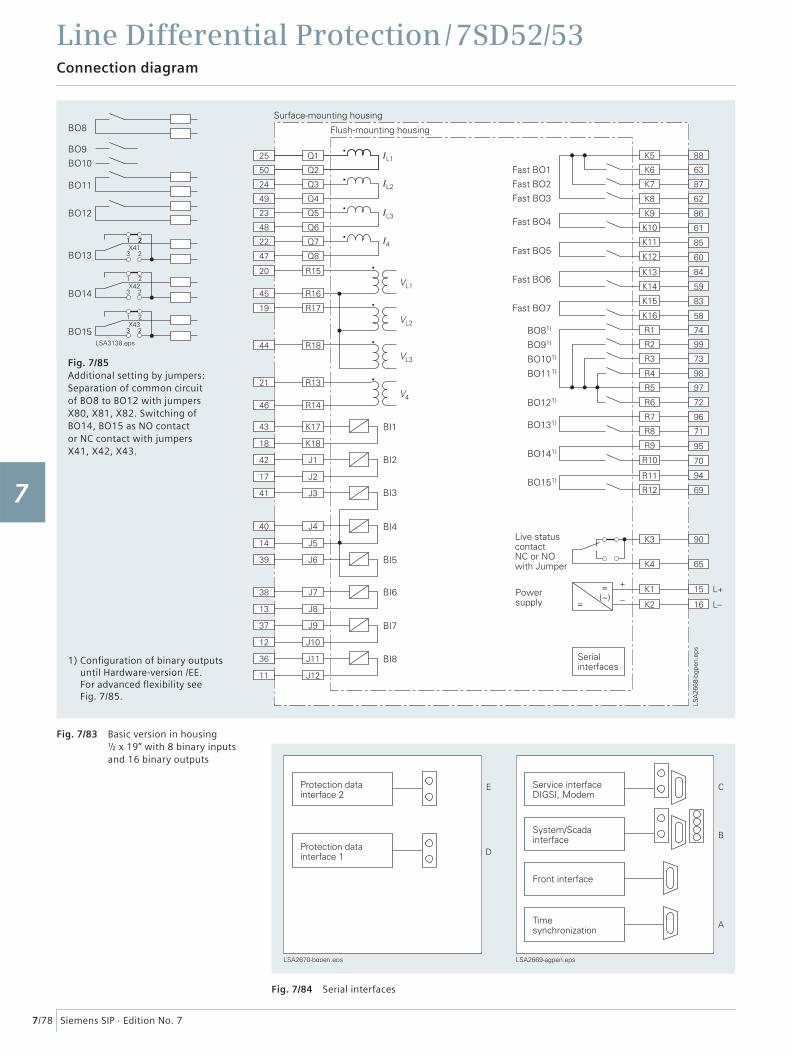
Line Differential Protection / 7SD52/53Connection diagram
7/78 Siemens SIP · Edition No. 7
Fig. 7/83 Basic version in housing ½ x 19” with 8 binary inputs and 16 binary outputs
Fig. 7/84 Serial interfaces
Fig. 7/85 Additional setting by jumpers:Separation of common circuit of BO8 to BO12 with jumpers X80, X81, X82. Switching of BO14, BO15 as NO contact or NC contact with jumpers X41, X42, X43.
1) Confi guration of binary outputs until Hardware-version /EE. For advanced fl exibility see Fig. 7/85.
1
2
3
4
5
6
7
8
9
10
11
12
13
14
15
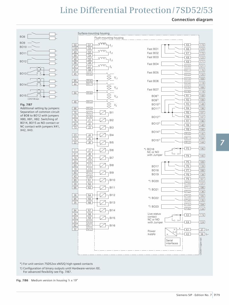
Line Differential Protection / 7SD52/53Connection diagram
7/79Siemens SIP · Edition No. 7
Fig. 7/86 Medium version in housing � x 19”
*) For unit version 7SD52xx-xN/S/Q high-speed contacts
1) Confi guration of binary outputs until Hardware-version /EE. For advanced fl exibility see Fig. 7/87.
Fig. 7/87 Additional setting by jumpers: Separation of common circuit of BO8 to BO12 with jumpers X80, X81, X82. Switching of BO14, BO15 as NO contact or NC contact with jumpers X41, X42, X43.
1
2
3
4
5
6
7
8
9
10
11
12
13
14
15
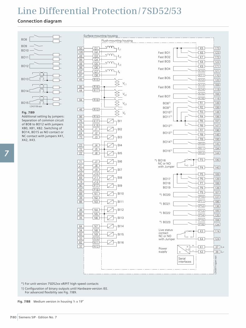
Line Differential Protection / 7SD52/53Connection diagram
7/80 Siemens SIP · Edition No. 7
Fig. 7/88 Medium version in housing � x 19”
*) For unit version 7SD52xx-xR/P/T high-speed contacts
1) Confi guration of binary outputs until Hardware-version /EE.For advanced fl exibility see Fig. 7/89.
Fig. 7/89 Additional setting by jumpers: Separation of common circuit of BO8 to BO12 with jumpers X80, X81, X82. Switching of BO14, BO15 as NO contact or NC contact with jumpers X41, X42, X43.
1
2
3
4
5
6
7
8
9
10
11
12
13
14
15