lindstrand balloons - cameron balloons modifications/support... · 10.06.99 29.06.01 27.09.01 29...
TRANSCRIPT
LINDSTRAND BALLOONS
MAINTENANCE MANUAL
For use with all Lindstrand Hot Air Balloons
LINDSTRAND BALLOONS MAESBURY ROAD
OSWESTRY SHROPSHIRE
SY10 8ZZ TEL: (01691) 671717 FAX: (01691) 671122
All rights reserved. No part of this manual may be reproduced or transmitted in any form or by any means, electronic, or mechanical, including photocopy, recording, or any information storage and retrieval system, without permission in writing from Lindstrand Balloons, Maesbury Road, Oswestry, Shropshire, SY10 8ZZ, England. LB HABMM Issue 1.0 Page i

Record of Amendments
No.
Date
Affected Pages
Approval
1
2
3
4
5
6
7
8
9
12.04.96 22.09.97 05.02.98 10.06.99 29.06.01 27.09.01 29.10.01 10.07.06 22.05.07
ii, iii, 16, 16a, 25, 62a, 62b ii, iii, iv, S1-1, S1-2, S1-3, S1-4, S1-5 ii, iii, iv, 28, 38, 65, S2-1, S2-2, S2-3, S2-4, S2-5, S2-6, S2-7, S2-8, S2-9 ii, iii, iv, S3-1, S3-2, S3-3, S3-4, S3-5, S3-6, S3-7, S3-8, S3-9, S3-10, S3-11 ii, iiia, iv, S4-1, S4-2 ii, 63, 63a, 64, 65, 66, 67 ii, iii, 66, 67 ii, 67 ii, iiia, iv, 20, 21, 21a, 22, 24, 25, 28, 33, 46, 46a, 63, 64, 65, 66, 67, S5-1, S5-2, S5-3, S5-4
S G Forse M Goodwin M Goodwin M Goodwin S G Forse S G Forse S G Forse S G Forse
Amendments This manual is kept up to date by amendments consisting of looseleaf pages, required to add new information or amend existing information. Pages affected by an amendment and the effective date are shown above. The pages themselves are identified by a change of the issue number at the bottom of each page. The number after the point in the issue number represents the amendment level of that page, eg the page marked Issue 1.4 is at Issue 1, modified by Amendment 4. LB HABMM Issue 1.8 Page ii

CONTENTS SECTION 1 - INTRODUCTION 1.1 Purpose of this Manual 1.2 Applicability 1.3 Identification of Systems 1.4 Qualification SECTION 2 - AIRWORTHINESS LIMITATIONS 2.1 Approval Statement 2.2 Mandatory Replacement Time 2.3 Structural Inspection Interval 2.4 Structural Inspection Procedure SECTION 3 - TECHNICAL DESCRIPTION 3.1 Envelopes 3.2 Baskets 3.3 Fuel Systems 3.4 Burners 3.5 Instruments 3.6 Part Numbers SECTION 4 - PREVENTATIVE MAINTENANCE 4.1 Paperwork 4.2 Envelopes 4.3 Baskets 4.4 Fuel Systems 4.5 Burners 4.6 Instruments 4.7 Hydraulic Remote Burner Control SECTION 5 - REPAIR AND MAINTENANCE 5.1 Envelopes 5.2 Baskets 5.3 Fuel Systems 5.4 Burners SECTION 6 - INSPECTION PROGRAM 6.1 Pre-Flight Inspection 6.2 100 Hour/Annual Inspection 6.3 Fabric Strength Test 6.4 Inspection After Overheating 6.5 Hydrostatic Structural Inspection SECTION 7 - SUPPLEMENTS Supplement No. 1 - Lindstrand Super Single Burner Supplement No. 2 - Jetstream Series 2 Double, Triple and Quad Burners LB HABMM Issue 1.7 Page iii

CONTENTS Cont.... SECTION 7 - SUPPLEMENTS Supplement No. 3 – Series 2 Cloudhopper Bottom End Supplement No. 4 - Recommended Procedure for Disinfecting Hot Air Balloon Baskets Supplement No. 5 - Easy Access Baskets LB HABMM Issue 1.9 Page iiia

MAINTENANCE MANUAL SUPPLEMENTS
Supplement No. Title
1 Lindstrand Super Single Burner
2 Jetstream Series 2 Double, Triple and Quad Burners
3 Series 2 Cloudhopper Bottom End
4 Recommended Procedure for Disinfecting Hot Air Balloon Baskets
5 Easy Access Baskets
LB HABMM Issue 1.9 Page iv

SECTION 1 INTRODUCTION 1.1 Purpose of this Manual This Maintenance Manual provides information on the following aspects of a Lindstrand Balloons hot air balloon: Airworthiness Limitations Technical Description Preventative Maintenance Repair and Maintenance Instructions Inspection Programs In total, this information is intended to provide an owner, operator, or repairer, with sufficient guidance so that the balloon may be preserved in an airworthy condition. If any detailed information cannot be found in this manual, then the factory should be contacted at the address shown on Page i. All relevant parts must meet the requirements specified in this manual. Use of un-approved parts or sub-standard materials will invalidate the Certificate of Airworthiness. Deviation from the repair instructions and material specifications contained in this manual, are not permitted without prior written consent from Lindstrand Balloons. 1.2 Applicability The information contained within this manual applies to all hot air balloons manufactured by Lindstrand Balloons. See Section 3, Technical Description, for a comprehensive list of models covered. 1.3 Identification of Systems All major components of Lindstrand hot air balloons are identified by a serial number and a description. These are located as follows: Envelope - Engraved on the crown ring and on an identification plate, which is situated on the top side of the envelope mouth. Burner - Engraved onto the top of the cross-over valve. Basket - Engraved onto a plate screwed onto the basket sidewall. Cylinder - Engraved on a plate which is fixed to the bottom foot ring of the cylinder. It is important that the relevant serial number is quoted when communicating with Lindstrand Balloons. 1.4 Qualification This manual has been segmented so that the preventative maintenance which may be undertaken by the owner/operator, and any other servicing instructions which have no effect upon the airworthiness status of the balloon, are included within Section 4, Preventative Maintenance. All other maintenance and repair, including the annual/100 hour inspection, must be accomplished by an appropriately approved inspector. LB HABMM Issue 1.0 Page 1

SECTION 2 AIRWORTHINESS LIMITATIONS 2.1 Approval Statement This manual provides the maintenance information required under Section BCAR 31.82. 2.2 Mandatory Replacement Time There are no components of any of the Lindstrand range of balloons which are required to be replaced after a fixed length of time. 2.3 Structural Inspection Interval The structural inspection interval for Lindstrand balloons is 100 hours operation, or one year; whichever is the sooner. In addition, if the balloon has 250 or more hours of operation at the time of inspection, a fabric strength test must be performed. 2.4 Structural Inspection Procedure The instructions for the structural inspection procedure are specified in Section 6.2.4 of this manual. The instructions for the fabric strength test are contained within Section 6.3. LB HABMM Issue 1.0 Page 2
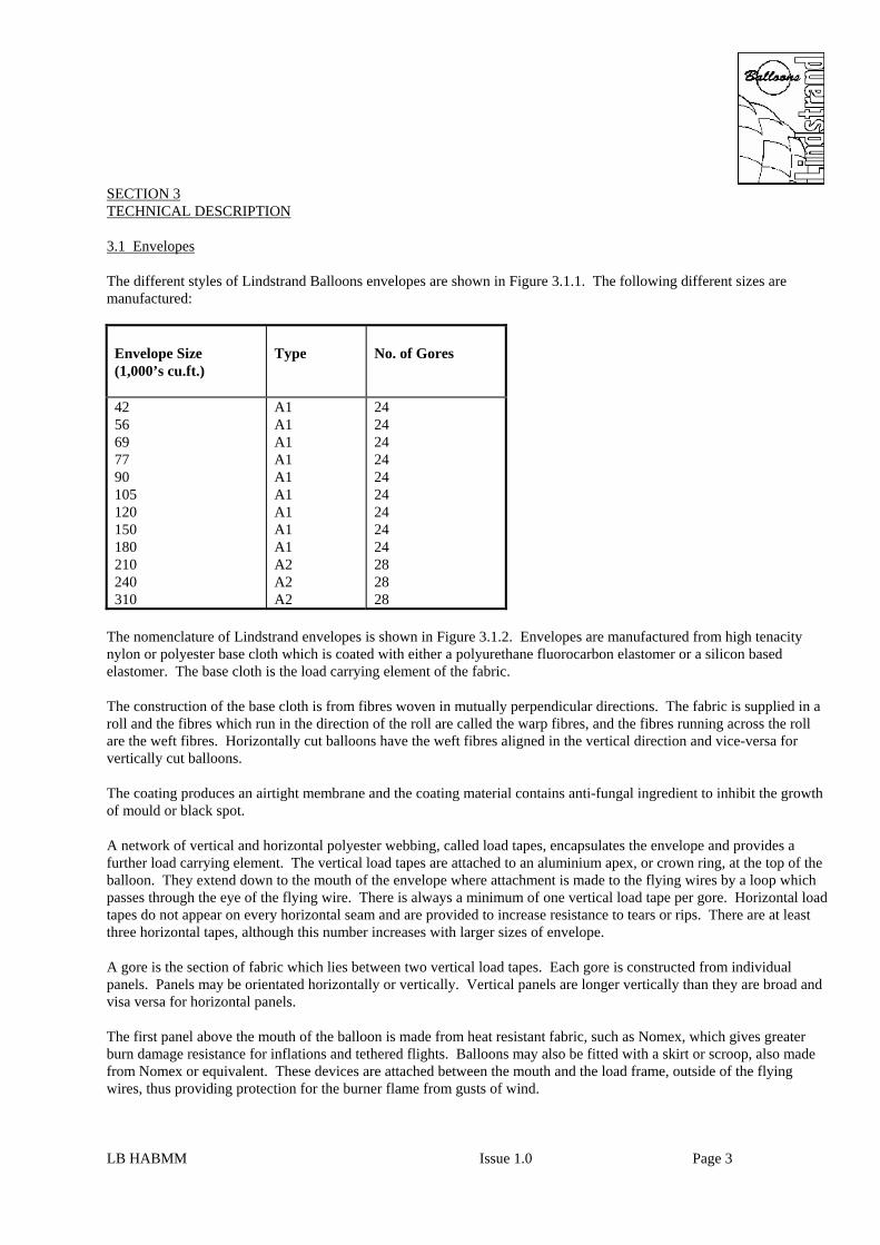
SECTION 3 TECHNICAL DESCRIPTION 3.1 Envelopes The different styles of Lindstrand Balloons envelopes are shown in Figure 3.1.1. The following different sizes are manufactured:
Envelope Size (1,000’s cu.ft.)
Type
No. of Gores
42 56 69 77 90 105 120 150 180 210 240 310
A1 A1 A1 A1 A1 A1 A1 A1 A1 A2 A2 A2
24 24 24 24 24 24 24 24 24 28 28 28
The nomenclature of Lindstrand envelopes is shown in Figure 3.1.2. Envelopes are manufactured from high tenacity nylon or polyester base cloth which is coated with either a polyurethane fluorocarbon elastomer or a silicon based elastomer. The base cloth is the load carrying element of the fabric. The construction of the base cloth is from fibres woven in mutually perpendicular directions. The fabric is supplied in a roll and the fibres which run in the direction of the roll are called the warp fibres, and the fibres running across the roll are the weft fibres. Horizontally cut balloons have the weft fibres aligned in the vertical direction and vice-versa for vertically cut balloons. The coating produces an airtight membrane and the coating material contains anti-fungal ingredient to inhibit the growth of mould or black spot. A network of vertical and horizontal polyester webbing, called load tapes, encapsulates the envelope and provides a further load carrying element. The vertical load tapes are attached to an aluminium apex, or crown ring, at the top of the balloon. They extend down to the mouth of the envelope where attachment is made to the flying wires by a loop which passes through the eye of the flying wire. There is always a minimum of one vertical load tape per gore. Horizontal load tapes do not appear on every horizontal seam and are provided to increase resistance to tears or rips. There are at least three horizontal tapes, although this number increases with larger sizes of envelope. A gore is the section of fabric which lies between two vertical load tapes. Each gore is constructed from individual panels. Panels may be orientated horizontally or vertically. Vertical panels are longer vertically than they are broad and visa versa for horizontal panels. The first panel above the mouth of the balloon is made from heat resistant fabric, such as Nomex, which gives greater burn damage resistance for inflations and tethered flights. Balloons may also be fitted with a skirt or scroop, also made from Nomex or equivalent. These devices are attached between the mouth and the load frame, outside of the flying wires, thus providing protection for the burner flame from gusts of wind. LB HABMM Issue 1.0 Page 3

LB HABMM Issue 1.0 Page 4

LB HABMM Issue 1.0 Page 5

The envelope is attached to the basket using stainless steel flying wires. There is normally one flying wire per gore. In flight venting of hot air and the final envelope deflation is achieved using a parachute valve which is situated at the crown of the envelope (see Figure 3.1.2). It consists of a large disc of material which is retained in position laterally below a hole in the envelope. The hole in the envelope is spanned by the vertical load tapes which prevent the parachute from being forced through the hole. The lateral position of the parachute is controlled by radial cords which attach to the outer rim of the parachute and the main envelope. These are called retaining lines. The parachute is operated by pulling on a red and white line in the basket. This transfers a vertical downwards force to a pulley which is at the confluence point of a number of pull-down lines attached to the edge of the parachute disc. The parachute disc is removed from the hole and hot air escapes from the envelope. When the operating line in the basket is released, the parachute reseals itself under the action of internal pressure. An optional velcro rip panel can be fitted as well as the parachute on larger envelopes (see Figure 3.1.3). A larger aperture can be created at the end of a flight by removing the rip panel to permit faster deflation. The rip panel is of circular shape, situated at the crown of the balloon. Velcro is attached both to the edge of the panel and to the balloon. The red operating line runs from the basket, through four pulleys, and is tied off to the side of the envelope. Three of the pulleys are situated on the edge of the rip panel. Pulling the red line first causes a number of riplocks to break which warn the pilot of the nature of this panel. Progressive pulling causes the velcro joint to separate, thus revealing a large opening for the escape of hot air. The rip panel will not reseal itself once the rip line has been pulled. Envelopes can also be equipped with rotation vents (see Figure 3.1.2). These vents are located around the envelope equator and consist of a break in the fabric which can be opened to allow air to be ejected tangentially. Operation is by a control line running up to a pulley which is fixed to the side of the envelope. The line then runs across to the rotation vent. Vents are often arranged in matched pairs and in this case, the pulley is attached to the operating cords of the second vent to permit them to be operated together. Once the force is released from the operating line in the basket, the internal air pressure causes the vents to reseal. 3.2 Baskets All Lindstrand baskets are made from wicker, with a marine grade plywood floor (see Figure 3.2.1). This floor is strengthened and protected on the underside by the addition of three or four runners, depending upon the size of basket. The wickerwork is woven between two tubular stainless steel frames. These frames provide strength and stability to the wickerwork. The marine plywood floor is laced onto the lower stainless steel frame. This permits the basket floor to be replaced if necessary. All loads are carried by 6 mm (¼") stainless steel wires which form a continuous sling around the basket. These wires are of 7 x 19 construction. The wires are attached to the load frame by a carabiner. They then pass down to the top of the basket, running adjacent to a nylon pole, through a sleeved hole in the top frame. The wires pass through the wickerwork and then through sleeved holes in the bottom basket frame. They pass through and across the wooden floor, under the runners. The wires are locked into one of the runners by providing a recessed hole in the runner in which sits an extra swaged ferrule. The portion of the basket wires above the top frame is protected by a PVC covering. The joint between the bottom basket frame and the floor is protected by rawhide which is stapled and laced onto the floor and wickerwork respectively. Extra rawhide strips are stapled over the basket wires where they run across the bottom of the floor, to provide protection. In larger baskets, there are four separate basket wire slings which surround the basket. The top basket frame has four upward facing sockets welded in place. Four nylon rods are inserted into these sockets and into similar downward facing sockets on the load frame. This provides a rigid support for the load frame and burner. The nylon rods, basket wires and burner hoses are covered with padded covers, to prevent damage. LB HABMM Issue 1.0 Page 6

LB HABMM Issue 1.0 Page 7

LB HABMM Issue 1.0 Page 8

The top basket frame is covered with dense foam and then finished with suede or leather, which is laced on. Within the weave of the basket are included rope handles, both internally and externally. The internal handles are provided for occupants to hold onto during faster landings. At least one handle is provided per occupant. Larger baskets are internally segmented to provide greater comfort for occupants. Partition walls are normally made from wicker, reinforced with vertical steel tubes. The ends of the partitions are connected to the outer walls of the basket using wicker. This provides for increased basket stability, whilst allowing sufficient flexibility for impact resistance. All Lindstrand basket floors have holes provided to permit fluids to drain through the floor. The minimum number is two, but on larger baskets there may be ten or twelve. On larger baskets, the internal walls are often padded. Internal padding sections are laced into place. Strengthened holes are created within the wickerwork to permit various items such as fuel cylinders, instruments and flight bags, to be restrained in position during flight. A wide variety of sizes of baskets are available. Smaller open baskets may have a straight top or swept profile. All larger baskets are straight topped. (See Figure 3.2.2). 3.3 Fuel Systems The LPG (Liquid Petroleum Gas) fuel is stored within special lightweight cylinders for in-flight use. The fuel is stored under sufficient pressure to ensure that it is in the liquid form. (See Figure 3.3.1). 3.3.1 Equipment Fitted to all Flight Cylinders 3.3.1.1 Liquid Withdrawal System This consists of a tube which descends almost to the bottom of the cylinder. It is attached to a valve and connector at the top of the cylinder. When the valve is open and with a suitable supply hose connected, the internal pressure forces liquid out of the cylinder. The liquid valve may be a screw type or a ball type valve. The connector is either the Tema or Rego type. 3.3.1.2 Contents Gauge The contents gauge is centrally mounted in the top dome of the cylinder. There is a float attached to a rotating arm. Changing levels of liquid in the cylinder cause the arm to rotate. A geared system links this movement to a magnet mounted in the top of the gauge. This magnet causes the needle within the dial to register the remaining contents. The length of gauge is different for differing sizes of cylinder. 3.3.1.3 Pressure Relief Valve The pressure relief valve may be integral within the vapour withdrawal valve, or separately mounted in a boss on the top dome of the cylinder. Irrespective of the type, the principle of operation is the same. A powerful spring holds a cone type valve in place, preventing any leakage. When the internal pressure of the cylinder reaches a certain level, the cone valve is forced away from the sealing surface, thus allowing the pressure to escape. The set level for all cylinders is 25 bar (375 psi) and this prevents the cylinder rupturing explosively when the pressure increases. 3.3.1.4 Maxfill (Ullage) Valve This is a small screw valve attached to a long tube which extends into the top dome of the cylinder. It is opened when the cylinder is being refuelled to permit the operator to determine when the cylinder is full. This is achieved by watching for the presence of liquid escaping from the valve. The length of the attached dip tube varies with the size and type of cylinder, to ensure that a 15% of volume vapour space is left when the cylinder is full. LB HABMM Issue 1.0 Page 9

LB HABMM Issue 1.0 Page 10

LB HABMM Issue 1.0 Page 11

3.3.2 Optional Equipment 3.3.2.1 Vapour Withdrawal Valves A vapour withdrawal boss is fitted to all cylinders. It consists of a tube which curves round inside the cylinder so that the entry is always positioned in the vapour space when the cylinder is upright. If the cylinder is to be used when laid over horizontally, the cylinder must be rotated to a pre-determined position to ensure that the end of the vapour withdrawal tube is still situated within the vapour space. This position is indicated by ensuring that the maxfill valve is lowermost on stainless steel valves. On aluminium cylinders there are two holes in the protective top collar. These must be lowermost. A screw type vapour valve is fitted to the top of the cylinder to control the supply of vapour. Frequently, a vapour regulator is attached to the outlet of the vapour withdrawal valve. This reduces the vapour supply pressure to 0.5 bar (8 psi), which is suitable for supplying vapour pilot lights. 3.3.2.2 Cylinder Jackets Each different size and type of cylinder may be covered with a padded cordura fabric jacket. This jacket protects the cylinder and also provides cushioning for the occupants in an open type basket. The cylinder jacket may also have resistance heating wire incorporated into it. When this heating wire is connected to a suitable supply source (either 240V or 110V), it heats the outside of the cylinder, causing the vapour pressure of the fuel to increase. This aids burner performance in low ambient temperature conditions. 3.3.2.3 Fuel Manifolds Fuel manifolds may be used for the convenience of the pilot to provide interconnection between cylinders in the basket. This means that it is no longer necessary to disconnect the burner hoses from a cylinder to re-connect to a full cylinder. The manifolds consist of female connectors appropriate to the type of cylinders being used, and in the number of cylinders which require interconnection. Hoses and adaptors provide the connection between the cylinders. A male connector is provided in a suitable location for connection to the burner hose. Only manifolds manufactured by Lindstrand Balloons may be used with their balloons. 3.4 The Jetstream Burner The following versions of the Jetstream burner are available: a. Jestream Single b. Jetstream Double c. Jetstream Double plus CLF d. Jetstream Triple e. Jetstream Triple plus CLF f. Jetstream Quad The larger burners suitable for larger envelopes, as described in Section 1 of the Lindstrand Balloons Flight Manual, are essentially multiple copies of the single and/or double burners. For convenience, the most common burner size, the double, will be described. (See Figure 3.4.1). LB HABMM Issue 1.0 Page 12

LB HABMM Issue 1.0 Page 13

3.4.1 Overview of the Double Burner The Jetstream Double burner is a device for heating and directing air into a hot air balloon envelope. It can be fuelled by any aliaphatic hydrocarbon, provided there is sufficient pressure in the fuel storage vessels to provide the required fuel flow. The preferred fuel is commercial quality liquid propane (BS 4250 1975). The nominal power output of the burner is 2.83 MW, at a supply pressure of 7 bar. Fuel is supplied in the liquid form, from the cylinder to the main burner block, via an armoured hose. It enters a gallery in the main distribution block. The gallery provides fuel supply to the main vaporising coil valve, the liquid fire valve, the pilot light regulator and the pressure gauge. On the downstream side of the main blast valve is another valve which when turned on, allows fuel to flow into the second coil. The burner is also fitted with a high voltage piezo electric spark igniter. 3.4.1.1 Main Vaporising Burner Coil The coil is manufactured from 7 metre of 12.7 mm OD stainless tubing, arranged in a two start winding. It is of the conventional flow direction, with the fluid rising to the top of the coil and then descending into the square section jet ring. The jet ring is equipped with 28 jets, 21 of which are 1.3 mm diameter and the remainder are 1.6 mm diameter. 3.4.1.2 Main Burner Valve and Liquid Fire Valve These two valves are of an identical basic design, but produced so that the valves are of differing lengths, in order to distinguish between the two different functions. The valves are of a plunger type with a handle attached by a rotating joint to a spindle. When the handle is moved from a horizontal plane into a vertical plane, the spindle is lifted. The spindle is attached to a valve seat by another rotating joint. When the spindle is lifted, this lifts the valve seal away from the valve seat, allowing fluid to flow through the valve. The fluid is prevented from leaking to atmosphere by the presence of a spring energised PTFE lip seal, situated on the spindle. This type of seal has been used with propane before with high reliability. It has low friction and the internal spring ensures that even at low temperatures and pressures, there is sufficient radial compression to achieve 100% sealing. The design of the seal body itself is such that with increasing differential pressure, the radial sealing force increases. An extra seal is also provided further up the spindle which prevents the ingress of contamination. Due to the action of the handle on the spindle, there are forces which act in a radial direction on the spindle. For this reason, a bush is included at the top of the spindle to resist these horizontal forces. The bush is manufactured from a composite metal matrix, including a sintered bronze base filled with a PTFE lead mixture. This bearing provides excellent lubrication and does not require servicing. The valve spindle can be rotated independently of the valve seal, thus permitting the handle to be positioned as required by the pilot. The position of both the valve handles is on the lower base of the burner. This allows either handle to be used from any position in the basket with an operating action that does not cause excessive pilot fatigue. The difference in general size of the handles permits the pilot to select the type of burner that is required during flight, without having to look upwards. 3.4.1.3 Pilot Light Valve and Regulator The pilot valve handle has been designed for easy operation, even when wearing heavy gloves. The outer rim of the handle and the main block have both been engraved, clearly showing the function of the valve and its position. (I = ON and O = OFF). In principle, the operation of the regulator has been arranged to provide high reliability with compactness. The function of the pilot valve and regulator have been combined so that the valve operates by over-riding the open/close action of the regulator. LB HABMM Issue 1.0 Page 14

The regulator is of the piston type to ensure small size. Two cleanable filters are also included in the regulator design, with a filtration size of 50 micron. One is situated before the inlet to the regulator and the other is positioned just before the pilot light jet. These filters prevent jet blockages. The pilot light itself is of the "pepper pot" type, which has excellent resistance to wind gusts and good high altitude performance. 3.4.1.4 High Voltage Ignition System A high voltage igniter is provided in the burner, contained within a waterproof heat resistant housing. The electrode is made from special steel which is highly resistant to prolonged high temperatures. The complete igniter assembly is sealed on the main block to prevent the entry of water. 3.4.1.5 Pressure Gauge A tailor-made pressure gauge is fitted into a recessed cavity within the main block, to provide an indication of the fuel pressure. It is connected into the main liquid feed and thus will provide an indication of pressure as soon as the cylinder valve is turned on. The gauge dial has a green sector marked upon it, which shows the correct operating pressure of the burner. A flow restrictor is included in the passageway which feeds the pressure gauge. This prevents damage to the gauge and tends to reduce vibration of the pointer, allowing for improved readability. 3.4.1.6 Liquid Fire The liquid fire nozzle is situated next to the pilot light inside the burner can. It is operated by opening the appropriately marked valve on the main burner block. It produces a stream of liquid propane which burns slowly, thus producing less noise than the main burner, for use when flying close to livestock. 3.4.1.7 Cross Over Valve This is a highly reliable "sandwich" type ball valve. The handle used is of the same design as the pilot light valve, to permit easy use even when wearing gloves. It is engraved with the internationally recognised symbols O = Off and I = On. These are aligned with a triangular datum marking on the valve block itself. The reverse face of the cross over valve is engraved with the burner serial number. 3.4.1.8 Main Burner Block The most important reason for designing the burner around a single distribution block, is the limitation of gas connections. Keeping the number of connections as low as possible contributes significantly to high reliability and simple maintenance. Great care has been taken to ensure that the complete block assembly is sealed to the burner can to prevent the escape of water. 3.4.2 Optional Commercial Liquid Fire (CLF) The Commercial Liquid Fire burner is a more powerful version of the liquid fire, producing approximately 3.7 MW of power at a supply pressure of 7 bar. It consists of a modification to a standard burner, involving the removal of the main vapourising coil and the insertion of a special 12 jet nozzle which fits onto the main coil post in the centre of the burner. In association with this, the operating valve handle is coloured red and the relevant engraving on the burner block changes to "CLF". In most cases, the normal liquid fire assembly is removed from the CLF burner in its entirety, and special machined blanks are inserted into the resulting holes. LB HABMM Issue 1.0 Page 15

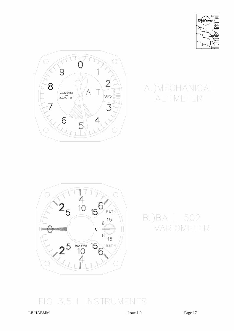
The basic burners that the CLF may be fitted into are the Jetstream Triple and Quad burners, in which they are described as the Jetstream Double plus CLF and Jetstream Triple plus CLF, respectively. The CLF burner is normally situated in a burner which is close to the pilot, to permit easy operation. 3.4.3 Triple Burner The Jetstream Triple burner is based upon the Double burner, with the addition of a specially manufactured third burner, to form a delta shape. The third burner is normally "slaved" to one of the other burners, in that there is a mechanical linkage which is provided between the main valve handle on one of the master burners, and the valve handle on the slave burner. This permits the slave burner to be operated in concert with one of the master burners. When the Triple is fitted with a Double-T basket, this mechanical linkage is optional. If the cross-over valve is opened on the master burner which has the mechanical cross linkage attached to it, then all three burners may be operated from one handle. Two liquid fire units are provided on the master burners. The mounting arrangement for both the Triple burner and the Double plus CLF variant is slightly modified to take account of the natural weight imbalance. One axis of rotation is provided in a central hub, whilst the other axis of rotation is achieved at the ends of an offset support tube. There are two settings provided at the ends of the support tube. One is for the Triple burner and the other for the Double CLF burner. 3.4.4 Quad Burner The Jetstream Quad burner is a straightforward duplication of the Double burner, with a few additions. As for the other multi-burners, mechanical linkages which may be selected off or on are provided to connect the main blast valve of each burner unit. By using these linkages in association with the standard cross-over valves, all four burner coils may be operated from one burner handle. The mounting arrangement for the burner is modified so that both axes of movement are provided on a central hub. The force required to move the burner is adjustable by a variable friction housing incorporated within the central hub. 3.4.5 Hydraulic Remote Burner Control The hydraulic remote control enables the Lindstrand range of burners to be operated in the conventional manner or by a remote hand held lever. The system includes a low spill quick release coupling which enables the lever assembly to be removed for storage. 3.5 Instruments 3.5.1 Altimeter The standard altimeter which is fitted into the Lindstrand instrument packs, is mechanical in its operation. The principle of operation is that changes in atmospheric pressure cause a change in the physical height of an aneroid capsule within the altimeter. This movement is converted into movement of the pointers by various linkages and gear systems. A sub-scale is also provided, which is calibrated in either millibars or inches of mercury. The sub-scale setting may be altered by a setting knob, to allow for changes in atmospheric pressure. All repairs and calibration of this type of altimeter must be undertaken by an approved instrument repair station. One type of mechanical altimeter is shown in Figure 3.5.1 a). 3.5.2 Ball 502 Variometer The Ball 502 variometer uses an electric transducer to sense changes in atmospheric pressure, and the electrical derivative of the altitude voltage is the rate of climb. An altitude compensation circuit is also included, which permits the calibration of the unit to be maintained between sea level and 20,000 cu.ft. LB HABMM Issue 1.1 Page 16

There are two sensitivity settings on the 502 instrument, either 600 or 1500 fpm. The unit is powered by a 9 V radio type battery (eg Duracell MN 1604), and has the capacity for two to be mounted on the rear of the unit. When battery power diminishes, the pointer will oscillate about the zero position. When the unit is first switched on, the needle will show the maximum climb or descent rate for approximately 10 seconds, before settling down to zero. See Figure 3.5.1 b). LB HABMM Issue 1.1 Page 16a
LB HABMM Issue 1.0 Page 17

3.5.3 Ball 655 Instrument Pack This is a combined instrument package comprising of a two-scale electric variometer, an electric digital altimeter and a digital envelope temperature pyrometer. The case is made of black plastic, with a removable back cover which allows simple access to the two independent power supply batteries. The electric analog variometer contains a small silicon absolute pressure transducer, with an output voltage proportional to altitude. This voltage is differentiated to give the rate of climb reading. The altimeter is a digital voltmeter calibrated to read the transducer's voltage in either 1 foot or 1 metre steps from sea level up to 19,999 ft or 6095 m. The altimeter may be switched to read out the corrected barometer setting at the launch site. The barometer setting is adjustable with a set knob. See Figure 3.5.3. LB HABMM Issue 1.0 Page 18

LB HABMM Issue 1.0 Page 19

SECTION 4 PREVENTATIVE MAINTENANCE 4.1 Paperwork Any preventative maintenance work carried out by the balloon owner or operator, in accordance with the instructions contained within this section of the Maintenance Manual, must be documented with an entry in the balloon maintenance record, which includes the following information: a. A description of the work performed b. The date of completion of the work performed c. The name of the person performing the work 4.2 Envelopes 4.2.1 Cleaning and Storage Cleaning of envelopes should be accomplished using a weak detergent such as washing up liquid. This should be diluted with water and wiped onto the fabric. A vigorous scrubbing action must be avoided, as this can remove the fabric coating. Any abrasive cleaning fluid must not be used, neither should brushes, for the same reason. A special fabric cleaning fluid is available from the factory. Under no circumstances must the balloon be washed in any type of washing machine. Once cleaning is complete, the simplest method of drying out the balloon is to inflate it and keep hot until dry. Balloons can be stored overnight in a slightly damp condition, but leaving them packed wet for long periods will cause rapid fabric degradation. Dry as soon as possible. If it is not possible to dry a balloon prior to a long period of storage, fabric damage can be minimised by freezing the complete balloon in an industrial freezer and then drying out the envelope as soon as possible after thawing out. 4.2.2 Care of Velcro The effectiveness of velcro joints can be prolonged by regular cleaning of both halves, especially the pile half (softer half). Carefully remove all pieces of grass and other materials which tend to get trapped. 4.2.3 Crown Ropes Crown ropes frequently become damp during inflation and after landings. If this occurs, it is better to untie the knot at the crown ring and store the crown rope separately from the envelope in a dry location. The crown rope can be re-attached to the crown ring prior to inflation using a bowline knot. Envelopes manufactured after August 2003 are fitted with a stub tape loop on the crown ring. The crown line is attached to this loop using a 2,500 kg carabiner. This simplifies removal and correct replacement of the crown line. 4.2.4 Envelope Handling Envelopes should only be handled by the load tapes. This avoids fabric damage. Care should be taken with clothing worn by the pilot and the crew, so that sharp objects like badges or pins do not cause tears. Boots fitted with hook-type eyelets should be avoided for the same reason. LB HABMM Issue 1.9 Page 20

When laying out the envelope, carefully inspect the ground for hidden sharp objects. If an inflation directly on tarmac or gravel is necessary, avoid dragging the balloon across the surface and minimise the number of people treading on the fabric. If an internal inspection is necessary in this situation, it is best to remove your shoes. 4.2.5 Owner/Operator Envelope Repairs 4.2.5.1 Fabric Repairs Any damage in fabric below the first horizontal tape may be repaired by the O/O, using the instructions given in Section 5.1.2.2. Small repairs above the first load tape may be repaired by the O/O using the instructions given in Section 5.1.2.2.1. Repairs to load tapes anywhere on the envelope must be undertaken by a qualified repairman or facility. 4.2.5.2 Control Line Repairs The parachute operating line and turning vent control lines may be replaced using approved components and following the instructions provided in Section 5.1.2.7 and 5.1.2.9. The envelope must be inflated and the correct operation of the replaced lines established prior to flight. 4.2.5.3 Carabiners Carabiners may be replaced as required on a like for like basis or by using the Lindstrand 5,000 kg carabiner. 5.2.5.4 Banners Banners may be replaced or repaired by the O/O at any time. It is the responsibility of the O/O to ensure that the banners being installed are of the correct size and design for the attachment locations provided on the envelope. 4.2.5.5 Temperature Flag The fusible link which attaches the temperature flag onto gore number 1, the retaining line loop position, may be replaced by the O/O provided that the temperature tags are inspected and show a temperature not greater than 120ºC. The maximum recorded temperature must be written into the aircraft log book. 4.2.5.6 Kevlar Flying Wires Factory supplied replacement kevlar flying wires may be installed on 120,000 cu.ft. envelopes or smaller using a quick link (AC 1166). The screw gate of the quick link must be fixed in the closed position by using Loctite Nutlock 242. 4.2.5.7 Scoop Repair or Replacement Scoop repairs may be undertaken by the O/O using nomex material. Factory supplied replacement scoops may be installed. 4.3 Baskets The Owner / Operator may perform the following maintenance actions: a. Cleaning and re-varnishing of the basket. b. Replacement of side wall padding, passenger positioning blocks, cushion floor, and basket equipment such as a handling line or first aid kit. c. Repair or replacement of upper frame suede or leather. LB HABMM Issue 1.9 Page 21

d. Repair or replacement of leather or rawhide on bottom edge. e. Repair or replacement of internal or external rope handles. f. Replacement of factory supplied carabiners. g. Replacement of basket runner protection strips. 4.3.1 Cleaning, Storage and Re-Varnishing The best method of preserving the basket in good condition is to ensure that it is stored correctly between flights. The preferred storage environment for baskets is in a cool dry area. Hot dry areas should be avoided as the wickerwork tends to dry out and can crack more easily. Equally, damp areas should be avoided as this can cause rot. If hot temperatures are unavoidable, it is recommended that the wicker is regularly given a good hose down with water. Cleaning the wicker is best achieved in the same way. Mud which has dried onto the exterior can be removed using a pressure washer from inside the basket. The padding on the baskets can be cleaned using a suitable suede or leather cleaner as appropriate. It is best to keep the basket free of dirt. This is simply achieved by removing all basket equipment, cylinders, cushion floor, etc and removing any collected debris by a vacuum cleaner. Pay particular attention to the joint between the bottom basket frame and the plywood floor. The cushion floor foam can be cleaned using detergent and water. The baskets may be re-varnished to renew the protective layer. A good quality flexible varnish should be brushed on to the wickerwork. Avoid varnishing over the rope handles or suede covering. It is better to remove the suede or leather and padding on the basket top frame prior to varnishing. The varnish may be sprayed on to the wicker, for speed. 4.3.2 Basket Upholstery If the suede or leather trim covering the padding on the top frame is torn, it can be repaired as follows: Remove the damaged section of leather by carefully unlacing the cord holding the trim on to the basket. Cut a patch of replacement leather of the correct colour, which is 15 mm (5/8”) larger than the damaged section. Glue and/or stitch the patch on to the underside of the damaged section. Also, stitch the edges of the hole or tear on to the patch to avoid fraying at the edges. Replace the leather on the basket, lacing into place. 4.4 Fuel Systems 4.4.1 Fuel Cylinders Generally, the flight cylinders require little specific attention throughout their service life, provided that the following instructions are followed. 4.4.1.1 Handling Cylinders Whilst the cylinders are robust, care should be taken when moving them. Ensure that when the cylinders are placed on rough, uneven ground, that the cylinder is resting on the foot ring and not on the dome of the cylinder itself. LB HABMM Issue 1.9 Page 21a

4.4.1.2 Transportation of Cylinders It is best to transport the cylinders standing upright. Short journeys with cylinders laid down will not cause damage, but habitually transporting them on their sides can cause irrepairable damage. Cylinders should always be restrained from movement during transportation. 4.4.1.3 Cleaning of Cylinders Externally Cylinders may be washed using detergent and water. Avoid waterlogging the foam padding by removing the cylinder padding prior to washing. Difficult marks may be removed by using a solvent such as Trichloroethane (Genklene or MEK). The cylinders may be polished using a proprietry stainless steel cleaner, provided that it does not have a corrosive action. 4.4.1.4 Protection of Connectors Both Rego and Tema types of liquid connectors are provided with dust caps. These should be fitted over the male half of the connector which is situated on the cylinder to prevent the accumulation of dirt in the connector. Both styles of connector have an integral seal that prevents the flow of liquid propane if the female half of the connector is not connected. The connector is situated downstream of the main on/off liquid valve and there is the possibility of liquid becoming trapped between the valve and the connector seal if the fuel hoses are disconnected without bleeding the lines. If this trapped liquid is not vented, subsequent temperature increase will cause expansion, which tends to cause the seals within the connector to fail. It is a good habit to depress the connector nipple before the cylinder is stored. To prolong the life of the seals within the connector and to ease the connection process, it is a good habit to regularly lubricate the whole connector (both male and female halves). The recommended lubricant is silicon grease, in either the solid or spray form. However, if the balloon is operated in a dusty or sandy environment, the recommended lubricant is graphite powder. 4.4.3 Replacing Pre-Fabricated Fuel Hose If a section of fuel manifold requires replacement, the first action is to measure the hose length, as shown in Figure 4.4.3. Dismantle the manifold by unscrewing the various connectors from each end of the hose. Carefully note the types of end fittings on the hose and into which connectors the end fittings were screwed. Order a pre-fabricated replacement hose from the factory, specifying the measured length and the required end fittings. Assemble the new section of hose into the fuel manifold, making sure that new gaskets are used on all 3/8” BSP threads. Loctite 577 or 572 should be applied sparingly to the end of the male ¼” NPT thread. Once the assembly is complete, the whole manifold should be carefully checked for pressure integrity, using compressed air. 4.5 Burners All of the following maintenance actions may be undertaken by the Owner / Operator: 4.5.1 Storage and Handling of Burners The burners are the engine of the hot air balloon, and consequently should be stored with care. Ideally it should be stored suspended within the basket so that it cannot hit other items. A padded burner bag which sits on the basket top frame stubs is available, and is recommended. The burner may be placed on soft ground, resting on the burner coils, to assist in the insertion of the burner rods. Hard surfaces should be avoided wherever possible at this stage. Care should be taken when dismantling the basket and burner assembly, to avoid dragging unprotected connectors on the ground. It is recommended that the connector cover is always fitted to the connector before the burner is taken down. LB HABMM Issue 1.9 Page 22

LB HABMM Issue 1.0 Page 23

4.5.2 General Cleaning During the operation of the burner, there is inevitably an accumulation of carbon deposits (soot) within the coil and can of the burner. These deposits may be removed by using a solvent soaked cloth. 4.5.3 Jet Blockages In some instances, the main jets and/or pilot light jets may become blocked due to foreign particles contained within the fuel. These may be rectified as follows: a. Main Jets Blockages of main jets cannot normally be detected through a loss of performance, unless a substantial number of the main jets are blocked at the same time. Using a torch, shine light down onto the jet holes and look for any debris lodged in the jets. Remove the jets which are blocked and carefully insert a pin into the hole, forcing any debris out backwards. Replace the cleared jet. Do not use any gas sealant on the jet threads. Only tighten the jets by ¼" of a turn, to avoid shearing the jet. b. Pilot Light Jets
Blockage of pilot light jets will cause a complete malfunction or erratic performance. To gain access to the pilot light jet, first unscrew the pilot light cup and heat exchange tube as one unit. Remove the pilot light jet by unscrewing it and clean in the same way as the main jets. The hole in the pilot jets is very small, but if held up to a light, the hole should appear round. A special pilot light jet cleaning tool is available from the factory. Alternatively, a jet cleaning tool for a tilley lamp or a gas camping stove may be used. Replacement is the reverse of removal.
4.5.4 Adjustment of Slurper Tube See instructions in Section 5.4.8. 4.5.5 Piezo Ignition Unit Adjustment See instructions in Section 5.4.7. 4.5.6 Gimbal Adjustment The stiffness of the burner gimbal movement may be adjusted to suit the individual requirements of the pilot. See the instructions in Section 5 or in the supplements for the different burner designs. 4.6 Instruments In general, there are no easily serviceable items within any of the instruments used with Lindstrand balloons, with the exception of battery replacement. If any difficulties are experienced, the instruments should be either returned to Lindstrand Balloons, or in the case of instruments manufactured by Ball Variometers Inc, these may be returned direct to Ball at: Ball Variometers Inc 6595 Odell Place Suite C Boulder CO 80301 USA Tel: 303 530 4940 LB HABMM Issue 1.9 Page 24

The mechanical altimeters may be serviced by any approved aviation instrument specialist. 4.6.1 Battery Replacement The batteries in the 502 variometer are located on the rear of the instrument. Unscrew the four screws which hold the mounting plate into the instrument box. Lift out the instrument package and turn over. Remove the battery from the carrier on the base of the variometer and replace with a new one. The batteries in the Ball 655 instrument pack are located within the casing. Unscrew the two retaining knobs on the rear of the casing. Lift off the back cover to reveal the two batteries. It is advised that both batteries are replaced at the same time. 4.7 Hydraulic Remote Burner Control 4.7.1 Handling and Storage The hand held lever assembly should be removed and stored in a manner which prevents damage to the assembly and hoses when not in use. During normal operation, the lever assembly can be adjusted to give the most comfortable feel and to remove any slack in the system by tightening or slackening the two grub screws on the lever. LB HABMM Issue 1.9 Page 25

SECTION 5 REPAIR AND MAINTENANCE 5.1 Envelopes 5.1.1 Envelope Construction Materials It is important to ensure that any repairs performed on the envelope are achieved by using the correct material. This section describes the materials to be used. In case of doubt, please consult the factory. 5.1.1.1 Envelope Fabric One of two fabrics may be used in the construction of the envelope: The standard fabric (N1053) is a high tenacity woven ripstop nylon with a soft polyurethane flurocarbon elastomeric coating. The finished weight is 58 grammes/sq metre (1.71 oz/sq.yard). The tensile strength in both the warp and weft directions is 58 kg/50 mm (65 lbs/in). The fabric is supplied on 1.4 m wide rolls (55") and this complete width will be required for some panel replacements. The high strength fabric (N2268) is a heavier nylon base cloth with a silicon elastomeric coating. The finished weight is 90 grammes/sq metre (2.65 oz/sq.yard). The tensile strength in both the warp and weft directions is 100 kg/50 mm (112 lbs/in). The fabric is supplied in the same roll width as the standard fabric. Other equivalent specification fabrics may be used for repairs, provided permission in writing is obtained from Lindstrand Balloons. 5.1.1.2 Load Tapes Several of the load tapes used are common to all Lindstrand envelopes. The top rim tape is always 25.5 mm (1") wide, with a tensile strength of 2000 kg (4,400 lbs). The bottom rim tape is always 50 mm (2") wide tape. The tensile strength is greater than 2,000 kg, but this wider tape is used mainly to provide greater tolerance to burn damage in the mouth area. All other horizontal and vertical tapes are defined on Table 1. TABLE 1 - VERTICAL AND HORIZONTAL LOAD TAPE SPECIFICATIONS Envelope Size
Type Vertical Tape Horizontal Tape
Width Strength Width Strength mm in Name kg lbs mm in Name kg lbs 42 56 69 77 90 105 120 150 180 210 240 310
A1 A1 A1 A1 A1 A1 A1 A1 A2 A2 A2 A2
19 19 19 19 19 19 19 19 19 19 19 25
¾ ¾ ¾ ¾ ¾ ¾ ¾ ¾ ¾ ¾ ¾ 1
58402 58402 58402 58402 59055 59055 59055 59056 59056 59056 59056 59036
650 650 650 650 1000 1000 1000 1400 1400 1400 1400 1950
1430 1430 1430 1430 2200 2200 2200 3080 3080 3080 3080 4290
19 19 19 19 19 19 19 19 19 19 19 19
¾ ¾ ¾ ¾ ¾ ¾ ¾ ¾ ¾ ¾ ¾ ¾
58402 58402 58402 58402 58402 58402 58402 58402 58402 58402 58402 58402
650 650 650 650 650 650 650 650 650 650 650 650
1430 1430 1430 1430 1430 1430 1430 1430 1430 1430 1430 1430
LB HABMM Issue 1.0 Page 26

5.1.1.3 Sewing Threads The thread that is used on the needle is Metric 30 (V69), three strand continuous filament polyester, of plaited construction. The thread used on the bobbins is Metric 30 (V69), three strand continuous filament polyester, of twisted construction. Both threads should be treated to provide increased resistance to ultra-violet exposure. A comparable US specification is V-T-285, size E. Nomex thread is recommended for sewing the envelope components made in Nomex, but it must not be used elsewhere. No other thread types are permitted without the written consent of the Chief Engineer at Lindstrand Balloons. 5.1.1.4 Envelope Cordage 5.1.1.4.1 Parachute Retaining Lines 2 mm (1/16”) diameter plaited aramid rope, with a tensile strength of at least 250 kg (550 lbs). 5.1.1.4.2 Parachute Pull Down Lines 2 mm (1/16”) diameter polyester plait cord, with a tensile strength of at least 75 kg (165 lbs). 5.1.1.4.3 Parachute Operating Line 8 mm (5/16”) diameter aramid core with polyester overbraiding, with a tensile strength of at least 1750 kg (3850 lbs). The polyester outer covering of the parachute operating line must be a red and white 50/50 spiral. The polyester outer covering of the rip panel operating line must be completely red. No deviation from this colour scheme is permitted. 5.1.1.4.4 Rotation Vent Lines 3.5 mm (1/8”) aramid core with polyester overbraiding, with a minimum tensile strength of 400 kg (880 lbs). The outer covering is green for right rotation and black for left. 5.1.1.4.5 Rip and Superchute Lines Solid red, as 5.1.1.4.3. 5.1.1.5 Flying Wires Flying wires are either 3 mm (1/8”) or 4 mm (5/32”) diameter 7 x 19 RHOL construction, made from AISI 316 stainless steel. The minimum strength, including the swaged ends, must be 480 kg (1056 lbs) for the 3 mm wires, and 900 kg (1980 lbs) for the 4 mm wires. Replacement wires must meet the above specification. If imperial sized wires are used, then it is important that the correct ferrule is used in the swaging process. All ferrules must be copper. The thimble size must fit over a 12.7 mm (½") diameter bar. The swaging process used in original manufacture is the Talurit system. The Nico press system, as described by FAA document EA-AC 43.13-1A and 2A, is a suitable alternative. The cut end of the wire and the ferrule may be covered with thick PVC heatshrink with impregnated bonding. If this is not available, the cut ends of the wire must be covered with an adhesive tape to avoid damage to the envelope when packing. Once the swaging process is completed, the resulting wire rope assembly must be proof tested to 60% of the minimum strength quoted above, for the particular size of wire, for three minutes. LB HABMM Issue 1.0 Page 27

5.1.1.6 Fibre Joint Fabric (Velcro) The only size of fibre joint fabric used structurally is the 50 mm (2") wide standard strength version. This is used on both parachute retaining patches and velcro rip panels. High strength versions must not be used. 25 mm (1") wide fibre joint fabric is used for attaching banners to the outside of the envelope. 5.1.2 Envelope Repairs 5.1.2.1 Sewing Machines The sewing machine used must make a Federal Specification 751 type 301 lock stitch. Chain stitching is not permitted anywhere on a Lindstrand envelope. The needle size used is 110 (18 Singer System). The stitch length is between 3.7 mm and 4.5 mm (5 ½ to 7 stitches/inch). The main structural seam used is the French Fell seam. This seam is best achieved using a twin needle machine with a needle spacing of 8 mm (5/16”). For this needle spacing an 11 mm (7/16”) folder may used to help create the seam. Alternatively, a twin needle machine with a 3/8” needle spacing may be used. 5.1.2.2 Fabric Repairs The type of fabric repair that must be achieved is dependent upon the size of hole or damaged section of fabric. 5.1.2.2.1 Sticky-Backed Patch If the longest dimension of a hole or tear is less than 75 mm (3"), then the hole can be repaired using sticky-backed fabric. This fabric is available in a variety of colours of repair rolls from the factory. The size of patch must be such that there is a minimum of 25 mm (1") overlap all around the damaged portion of fabric. The damaged panel should be laid out on a flat smooth surface so that there are no wrinkles in the fabric. A patch should be cut to cover the hole and then cut another mirror image patch. One patch should be placed inside the envelope covering the damaged portion, and then the other patch placed so that it is covering the first patch precisely on the outside of the envelope. Ensure that the resulting repair has not caused any distortion of the panel (see Figure 5.1.2.2.1.a.). Note that this repair method may not be employed if the damaged section of fabric extends to within 25 mm (1") of any load tape or seam. If this is the case, use the repair procedure given in Section 5.1.2.2.2. This repair method may not be employed on hyperlife fabric. Holes up to 250 mm (10") in any one dimension may be repaired using sticky-backed fabric, provided that a double row of stitching is run around the resulting patch with a 25 mm (1") stitching overlap (see Figure 5.1.2.2.1.b.). 5.1.2.2.2 Stitched Patch A single stitched patch can be used to repair any size of hole or damage in a panel, provided that the damage is not present on two adjoining panels and does not cross a seam. If the damage is within 25 mm (1") of a seam, the seam must be unpicked and the patch inserted so that it extends to the edge of the panel. The main fell seam can then be restitched as normal. Damage that crosses a seam can be patched by adding separate patches onto both panels and then re-creating the fell seam. It is recommended that if a hole covers more than half a panel area, or if there are more than three separate holes in a panel, then the panel should be completely replaced. LB HABMM Issue 1.9 Page 28

LB HABMM Issue 1.0 Page 29

a. Inlaid Patch Draw a rectangle around the damaged area. Ensure that the sides of the rectangle are aligned with the weave of the fabric. Measure the rectangle dimensions and then cut out the rectangle from the envelope. Each corner of the rectangle should be cut to a depth of 19 mm (¾”). Lay out the new replacement fabric and mark out a rectangle that is 80 mm (3 1/8”) larger in both directions than the original rectangle. Beginning at the centre of one edge, carefully fold the envelope fabric and patch fabric together to give the correct fell seam. Stitch the resulting seam together. This process is repeated for each edge. If one edge of the fabric patch is part of another seam, this edge is left until the seam is re-stitched together. This type of repair is best performed using a double needle machine. b. Overlaid patch This is a simple alternative to the inlaid patch procedures and it is recommended for the less experienced seamstress or sempster. Place a piece of wood inside the envelope under the section of damaged fabric. Using a hot knife, cut a rectangle around the damaged area, but round the corners as shown (see Figure 5.1.2.2.2). This prevents the edges from fraying. Cut a replacement patch that is 40 mm (1 ½") larger than the hole cut, in both directions. Fold the edges of the patch under to created a 20 mm (¾") seam. Pin the patch into position and secure with a single pass of a double needle machine, or two rows of stitching with a single needle machine. Ensure that there is at least 25 mm (1") of stitching overlap to prevent the stitching unravelling. With care, this repair will look indistinguishable from the inlaid patch method. 5.1.2.2.3 Panel Replacement Unpick all the seams on the panel, carefully removing any horizontal or vertical tapes. Unpicking is best achieved by breaking every third or forth stitch with a seam ripper or scissors and then carefully pulling the seam apart. The remaining threads should be completely removed from the fabric. The damaged panel should be kept as a pattern for the replacement. This is done by spreading the panel flat and drawing around it. If the damaged panel is too distorted from burn damage to provide a good pattern, then an identical panel can be measured up. A 19 mm (¾") seam allowance is added to all dimensions for the replacement panel. If difficulty is experienced in achieving a satisfactory replacement panel, then the factory can be consulted. The new panel is stitched into position using the structural fell seam already described. The repair stitching should overlap the original stitching by 100 mm (4") in each corner of the panel. It is simplest to sew the fell seam before sewing the load tapes onto the resulting seam. 5.1.2.3 Load Tape Repairs The maximum allowable damage to any load tape is a 5 mm (3/16”) reduction in load carrying width. To repair load tapes, unpick the damaged section and 300 mm (12") beyond each end of the damaged section. Measure the length of the damaged load tape and cut with scissors. The ends of tape remaining on the envelope must be sealed with a hot knife to prevent fraying. Cut a length of the correct type of tape, as shown in Table 1, Section 5.1.1.2, so that the total length is 500 mm (20") longer than the damaged section. Heatseal the ends of the replacement tape. Pin the tape into position so that there is a 250 mm (10") overlap at each end. Stitch the replacement tape to the original using either of the stitch patterns shown in Figure 5.1.2.3. Restitch the fabric onto the new section of tape using a double row of stitching. LB HABMM Issue 1.0 Page 30

LB HABMM Issue 1.0 Page 31

LB HABMM Issue 1.0 Page 32

5.1.2.3.1 Overlying Tape Repairs If any of the tapes which are overlying the parachute require replacement, this is achieved as follows: Cut the damaged tape at the point where it joins the top rim tape. Carefully unpick the tape from the locating tape and remove. Measure the removed length of tape and as a check, also measure an adjacent tape. All tape lengths should be identical. Cut a length of replacement tape which is 250 mm longer than the measured length of damaged tape. Stitch the replacement tape onto the original tape, as shown in Figure 5.1.2.3.1. Ensure that the stitching of the positional tape to the new overlying tape is in the same position as the removed tape. This is important for spreading the localised crown line loads. 5.1.2.3.2 Flying Wire Loops If the flying wires are damaged and are to be replaced with pre-made lengths of replacement flying wire, then attachment is achieved as follows: a. Unpick and remove the nomex pocket which surrounds the tape and wire joint. b. Unpick the inside length of load tape and remove the flying wire. c. If there is any damage to the tape itself, then this must be unpicked 250 mm beyond the damaged area. d. Cut a new length of correct tape which is 250 mm longer than the length removed. e. Stitch the new section of tape onto the existing tape, as shown in Section 5.1.2.3. f. Pass the new tape through the nomex pocket and the eye of the replacement wire. g. Turn the tape inside the envelope and stitch through both layers of tape and the sandwiched fabric with the stitch patterns shown in Figure 5.1.2.3. h. The resulting repair will look like Figure 5.1.2.3.2. Restitch the nomex pocket into place. 5.1.2.3.3 Internal Loops There are three types of internal loops. All loops are made from 19 mm (¾") wide tape, with a strength of 650 kg (1430 lbs). The differing types of loops are shown in Figure 5.1.2.3.3. 5.1.2.4 Flying Wires Flying wires which have become slightly discoloured due to overheating are safe provided they have not become too flexible Localised excessive stiffness in a flying wire indicated a weakening due to loss of strength and wire temper. Wires affected in this way should be replaced. Wires that are badly kinked or frayed should be replaced. If a wire requires replacement, it must first be measured for length, as shown in Figure 5.1.2.4. For Lindstrand A type envelopes, the following wire sizes are used: 42,000 cu.ft up to and including 150,000 cu.ft = 3 mm diameter wire (min. breaking strength 320 kg (704 lbs)) 180,000 cu.ft up to and including 310,000 cu.ft = 4 mm diameter wire (min. breaking strength 650 kg (1430 lbs) LB HABMM Issue 1.9 Page 33

LB HABMM Issue 1.0 Page 34

LB HABMM Issue 1.0 Page 35

LB HABMM Issue 1.0 Page 36

LB HABMM Issue 1.0 Page 37

Most wires are arranged in pairs around the lower thimble. This reduces the number of thimbles on the carabiner. If one leg of a pair is damaged, then both must be replaced. If swaging facilities are available, then the simplest method of flying wire replacement is to cut the loop of the flying wire where it attaches to the tape. This can be achieved using a pair of bolt croppers. The new wire is then swaged around the load tape loop. The thimble size must be large enough to fit over a 13 mm (½" bar). If ready-made flying wires are supplied, the fitting process is described in Section 5.1.2.3.2. Alternatively, pre-fabricated replacement wires may be attached to the envelope using a quicklink (Lindstrand Part No. AC1166) through the eye of the wire and the load tape loop. The screw gate of the quicklink must be fixed in the closed position by using Loctite Nutlock 242. 5.1.2.5 Parachute Retaining Lines It is rare that parachute cords require adjustment or repair. If attention to the parachute lines is required, first remove damaged cords. Measure the length of the relevant cord, or if it is broken, measure the length of the cord adjacent to it. Mark each end of the cord with five marks spaced 50 mm (2") apart. The kevlar cords should be cut with a pair of scissors, or sharp knife, and the ends bound with 3M tape, no. 365. When refitting the cords, note which mark is aligned with the loop on the parachute and on the envelope. Hold the correct mark in place and secure the line by tying a bowline knot as shown in Figure 5.1.2.5. Once complete, the envelope should be test inflated and the parachute positioning checked. 5.1.2.6 Parachute Pull Down Lines In the unlikely event that these lines require repair, remove the damaged line from the edge of the parachute. One length of cord runs from the edge of the parachute down to the pulley and back up to the other edge of the parachute. Once removed, measure the overall length of the line. Cut a replacement length of polyester cord of the correct size and heat seal the ends with a hot knife or lighter. Fold the line into two equal lengths and tie a loop at the mid point. Retie the resulting ends of the pull down lines to the loops on the edge of the parachute and re-attach the loop to the quicklink. Ensure that the screw gate of the quicklink is tightly fastened. 5.1.2.7 Parachute Line If the parachute line becomes excessively frayed or burnt, then it should be replaced in its' entirety. Undo all knots in the line and withdraw the line from the envelope. Measure the length of the line and cut a length of new rope of the correct type. Lindstrand envelopes are only fitted with an 8 mm (5/16”) aramid cored polyester braided covering line, which is red and white spiral in colour. Replacement line must be of this specification. Replacement of the line is the reverse of removal (see Figure 5.1.2.7 for rigging formats). The final securing to the loops sewn onto the envelope should be with a bowline knot, plus a safety knot. The safety knot will become jammed in the pulley if the bowline comes undone for any reason, thus allowing the parachute to still be operated. 5.1.2.8 Rip Lines Operating lines for both the velcro rip panel and the Superchute Deflation System are 8 mm (5/16”) aramid cored polyester braided line, which is solid red in colour. The replacement line must be of this specification. Undo all knots in the line and remove the line from the envelope. Use the old line to size the replacement line. Fit the new line in exactly the same way as the old line. It is recommended that several photographs are taken of the internal rigging of the envelope, on the flight prior to replacement of these operating lines. This information will greatly assist in the correct refitment. Once complete, inflate the envelope and deflate it using the replaced line to ensure that it operates correctly. LB HABMM Issue 1.3 Page 38

LB HABMM Issue 1.0 Page 39

LB HABMM Issue 1.0 Page 40

5.2 Baskets 5.2.1 Basket Wires If more than ten strands of a basket wire are broken, or if the wires are badly kinked, then a new section of wire must be spliced into the structure. The swaging process used in original manufacture is the Talurit system, using copper ferrules code no. 6.5 and stainless steel thimbles code no. 11-46. Alternatively, the Nico press process, described in FAA document EA-AC 43-13-1A and 2A may be used, provided that the wire and ferrules are compatible. 5.2.1.1 Damage Above Basket Top If the damaged portion of wire is 50 mm (2") above the top level of the basket, a new section of wire can be added as follows: a. Cut off the existing eye of the wire, just below the ferrule. b. Remove the PVC covering by sliding off. c. Cut a length of replacement wire that is sufficient, remembering to add approximately 200 mm (8") to create a new eye. d. Cut away the damaged section of wire. e. Swage the new section of wire onto the remaining existing wire. f. Slide a new section of PVC tubing over the wire. g. Erect the burner frame and attach all other basket wires. Form an eye using the correct thimble and ferrule.
Adjust the length with the assembly in its correct position. Mark the wires next to the ferrule. Remove the wire from the frame and swage.
h. File off any flash marks. i. Push the PVC over the resulting ferrule. 5.2.1.2 Damage Below Basket Top If a basket wire is unacceptably damaged below the level of the top frame, a new section may still be spliced in, but some care is needed with replacing new wire into the wicker itself. The procedure is as follows: a. Remove the rawhide in the area where the damaged wire passes through the floor. b. Cut away the existing eye of the damaged wire and slide off the protective PVC covering. c. Pull the wire down through the weave until there is 100 mm of slack at the bottom of the basket. d. Cut a length of new wire which is sufficiently long, remembering to allow approximately 200 mm (8") to create a new eye. Cut the existing wire at the base of the basket. e. Weld the new wire onto the old and then lubricate the new wire with vegetable oil or fat. LB HABMM Issue 1.0 Page 41
f. Swage the other end of the new wire to the existing wire so that the joint lies below the floor. g. Pull the existing wire and the new section of wire through the weave. Cut away the weld and clean the wire to remove the lubricant. The wire may be cleaned using trichloroethane or any equivalent de-greasing agent. h. Swage a new eye, following the procedures in Section 5.2.1.1. i. Replace the rawhide. 5.2.2 Basket Top Frames If the top frame of a basket becomes distorted, it may be repaired by using hydraulic jacks to straighten it. If rod sockets become distorted, these can be straightened by inserting a close fitting steel bar into the socket and bending straight again. If the top frame is cracked, it should be re-welded using a TIG welding set (Heliarc). The padding must be removed completely and the wicker moved aside to permit access. 5.2.3 Basket Floors If a floor is damaged so that a 250 mm (10") crack is visible on both sides of the floor, ie the floor has cracked right through, then it either must be patched or replaced totally. Patching is simply achieved by cutting a piece of similar thickness plywood which covers the cracked area and bonding it over the crack from the underside, using wood glue. Note that any protective varnish must be completely removed from the damaged area by sanding, prior to bonding the patch in place. Small tacks may be used to hold the patch in place whilst the glue is drying. If a floor and runner(s) are cracked, then it is easiest to replace the complete floor. The wooden runners are bonded to the basket floors for greater damage resistance. The bond strength is always greater than the wood strength, so removing runners from the floor is rarely practical. If a runner is damaged to the extent where it is no longer providing strength, then it is simplest to place another runner alongside and attach to the floor in a similar manner to the original. Replacement of the floor is achieved by the following procedure: a. Remove all rawhide from the basket bottom edge and from on top of the wires. b. Pull the basket wires back through the floor so that there is 100 mm (4") of slack in each wire. c. Unlace or cut the lacing holding the bottom frame onto the marine plywood floor. d. Cut slots into the sides of the plywood floor to release the wires from the floor. e. Cut slots into each of the runners to remove the wires from under the runners. Alternatively, the runners can be prised from the floor. f. Slide floor out from under the wires. g. If a replacement floor is being manufactured, it is best to use the old floor as a pattern for the hole positions. The holes through the floor which accept the basket wires, must be elongated into slots towards the edge of the floor to allow the existing wires to be replaced. h. New ash runners must be fitted in the same positions as the old. The underside face must be cut away with a router to provide a passageway for the wires. The runners are bonded onto the floor of the basket using wood glue and are also bolted together into recessed holes in the runners. The bolt hole pattern should be taken from the old runners. LB HABMM Issue 1.0 Page 42

i. The remainder of the rebuild process is essentially the reverse of dismantling. Rawhide should be soaked in water for at least 24 hours so that it is sufficiently pliable to ensure a close fit around the edges of the basket and over the basket wires. 5.2.4 Wickerwork Repairs Distortion of wickerwork does not affect the airworthiness of a basket. Excessive distortion can be removed by soaking the wicker in water for 48 hours and then placing a weight on the distorted area. The weight should be sufficient to remove the distortion. The wicker is then allowed to dry for another 48 hours with the weight in position. This process works on older baskets in which the original protective varnish has largely been removed. New baskets, with the varnish still intact, will not absorb the moisture as well. Once the wicker has dried for four or five days, it can be re-varnished using a good quality flexible varnish. Hard coating varnish should not be used as it cracks off the wicker quickly. Holes in the wickerwork which are large enough for a hand or foot to pass through are dangerous and must be repaired. Sometimes wickerwork will crack, leaving sharp ends or edges. Inspect the interior of the basket for any such damage which could cause injury. If any reweaving is necessary, it is best to do this with the wickerwork area to be fully pliable. Soak the area around the damage and any new cane for four days. Use a dull pointed tool to assist in feeding the new cane into the old. Copy the weaving pattern from the surrounding area to provide a neat repair. The cane should be cut to length as close as possible to the outside wall using sidecutters. Quite often, repaired sections of wicker are lighter in colour than the surrounding cane. Once the repair is complete, allow the cane to dry for two days. The wicker can then be varnished locally around the repair with a suitable colour dye in it, to reduce the colour difference. The remainder of the basket should be varnished as normal. 5.2.5 Rope Handles If the rope handles become excessively frayed or are broken, they can be replaced by reweaving the complete set of handles. Removal is achieved by first marking the rope at the extreme ends of each handle where they meet the wicker and cutting the damaged handle in the middle. Extract the rope handles from the weave using a dull pointed instrument, such as a screwdriver. Completely remove the handle rope and use it as a guide to cut a new length of rope, adding 100 mm to each end. Reweave the rope into the basket, taking care not to damage the wicker. The rope terminations are fed vertically up into the weave, normally in one of the basket corners. Interior handles are 16 mm (5/8”), exterior handles are 25 mm (1"). 5.3 Fuel Systems 5.3.1 Fuel System Safety When considering any work on fuel cylinders or fuel manifolds, it is important to ensure that there is no fuel remaining anywhere in the system. Fuel manifolds can be evacuated by connecting to a burner and operating the blast valve to expell any remaining liquid, or by depressing the sealing valve in one of the manifold connectors. To empty a cylinder which is full, it is best to fly with the cylinder and use up as much of the fuel as practical during the flight. If this is not possible then the most economic method is to transfer the contents to another cylinder using a transfer hose. Connect the two liquid withdrawal takeoffs together using the transfer hose. Open the liquid valve on both cylinders and the bleed valve on the cylinder to be filled. The difference in pressure will cause the cylinder to empty, although this is not a fast process. Alternatively, the contents can be burnt off using the burner in the normal manner. Once the cylinder is empty of liquid, open the bleed valve and leave the cylinder in an open, well ventilated area until all remaining pressure has been removed. This may take several hours. Unscrew the four screws which retain the liquid level gauge and carefully lift out the gauge. LB HABMM Issue 1.0 Page 43

5.3.2 Cleaning Cylinders Internally Once the contents gauge has been removed, it is good practice to clean the cylinder internally as follows: a. Use a pressure washer with detergent to clean through the gauge aperture. Empty the water from the cylinder by inverting. Turning the cylinder over should be achieved with care because when full of water, a V30 cylinder weighs 78 kg (172 lbs) and if dropped it could result in damage. b. Internal Inspection The most effective way of conducting an internal inspection on a cylinder is to lower a 12V bulb into the cylinder through the gauge hole. Inspect all the internal welds, especially on aluminium cylinders. If there is any evidence of corrosion or pitting of the surface surrounding the welds, a hydrostatic pressure test must be conducted to ensure the integrity of the cylinder. This test is best performed by the factory. c. Once the cylinder is empty of water, put some methylated spirt (alcohol) into the cylinder and swill it around to remove any remaining traces of water. Refit the contents gauge. Lubricate the new rubber seal with silicon grease to ease the assembly. 5.3.3 Liquid Withdrawal Valves 5.3.3.1 Screw Valves There are several types of screw valves that are used on cylinders and although they all operate in the same way, care must be employed when obtaining replacement parts because the components are not always interchangeable. There are two seals within the 1 ¼" ACME screw connector which seal the connection when the male half of the connector is in position, and if any leaks occur when the two are joined, these seals should be replaced. The outer seal is square in section and the inner round. The inner seal is removed using a piece of wire to hook behind it, taking care not to scratch the housing. Prior to replacement, the seals should be lubricated with silicon grease. Both seals must be present and in good condition in order to achieve a leak tight connection. If a leak occurs when the valve is open but the hose is disconnected, this means that the self-sealing nipple is faulty. Sometimes, the leak can be stopped by connecting the male half in order to reseat the nipple. However, if this does not stop the leak, the self-sealing nipple must be replaced. This is possible with a special tool available from the factory. Using the tool, the retaining disc is unscrewed and the nipple removed. Replacement is the reverse of this process. Any other faults with the valve cannot be repaired and the whole valve must be replaced. The cylinder must be completely emptied to achieve this. When replacing the screw valve, ensure that any excess flow device is removed prior to fitment. 5.3.3.2 Ball Valves Only one type of ball valve is used on the cylinders, the Worcester W44 valve. It may be configured with either a 1 ¼" ACME screw connector (commonly called the 'Rego' connector, after the original manufacturer), or a Tema 3/8" connector. In both cases, servicing of the valve itself is identical. There are two types of fault with this valve: a. Stem Leaks This can be recognised by liquid propane leaking out beside the nut, underneath the handle. Commonly, it can be rectified by removing the handle and holding the stem still using a spanner on the machined flats. Taking another spanner, the nut on the stem is tightened by 1/8 - ¼ of a turn. If this stops the leak, the valve handle is replaced and no further action is necessary. If the leak cannot be stopped, or the movement of the handle is unacceptably stiff, the valve must be disassembled and new seals inserted. LB HABMM Issue 1.0 Page 44
b. Ball Seal Leaks The ball valve must be dismantled to replace the ball seals or the stem seals and the cylinder must first be completely emptied, as described in Section 5.3.1.
Unscrew and remove the four retaining bolts. Carefully separate the face plate from the valve. Remove the two
seals situated on both sides of the ball, taking care not to scratch the body of the valve. Inspect the ball carefully for any dents or scratches. The ball can be removed from the valve by turning the handle into the off position. Unscrew both nuts on the valve stem and remove the handle. The stem can now be removed by withdrawing it into the valve and out one side. This reveals the glands on the stem which can be replaced (see Figure 5.4.5.2). The ball seals are simply placed on either side of the ball during reassembly. Silicon grease should be smeared onto the seals and the ball, the grease assisting to hold the seals in place while the two sides of the valve are replaced. The nuts on the four retaining bolts should be tightened in a diagonal pattern to a torque of 12.2 Nm (9 lbs ft). The stem nut should be tightened to a torque of 4.75 Nm (3.5 lbs ft). 5.3.3.3 Liquid Connectors Two types of liquid connector are used, the Rego or Tema types. The procedure for servicing the Rego 7141M type of connector is identical to the repair of the 1 ¼" ACME screw valve, as described in Section 5.3.3.1. The Tema 3800M connector has no serviceable components and should be replaced if found to be faulty. This is a simple matter of unscrewing the old and screwing on the new. New gaskets must be used. Ensure that the liquid valve is turned off before unscrewing the connector. 5.3.4 Vapour Valves If a vapour valve malfunctions it is necessary to replace the whole valve as there are no serviceable components with the valve. The cylinder must be completely emptied prior to removal of the valve. All Lindstrand cylinders are fitted with combined vapour and pressure relief valves. The correct types are the BMV SV25 and Fisher B600H. 5.3.5 Vapour Regulators The outlet of the vapour valve is fitted with a left hand POL thread. The regulator is screwed into this outlet. Regulators are set to 8 psi at the factory. The pressure setting can be altered in the following manner: a. BMV Type Regulator Remove the blue plastic blanking plug on the regulator. Insert the suitable size of hexagonal wrench (allen key). Turning the wrench clockwise increases the pressure, and anti-clockwise reduces the pressure. b. Calor Type Regulator Unscrew the locking nut situated on the threaded thumb screw. Turn the thumb screw clockwise to increase the pressure. Re-tighten the locking nut when the correct delivery pressure is reached. For normal flight conditions, the regulator delivery pressure should not need adjustment. If poor delivery is causing a weak pilot light flame, it is more likely that the regulator has malfunctioned and should be replaced in total. If the pressure setting requires changing for any other reason, a special setting rig is available from the factory and the factory should be consulted for advice on pressure setting levels. LB HABMM Issue 1.0 Page 45

5.3.6 Bleed Valve The bleed valve controls the maximum amount of fuel that the cylinder can carry. If it leaks, it must be replaced in total, for which the cylinder must be emptied. The dip tube length for V20, V30 and V40 cylinders is 176 mm (6 7/8”). The length for H40 and H55 cylinders is 72 mm. When replacing the bleed valve use either PTFE tape or Loctite 577 pipe sealant on the thread. 5.3.7 Contents Gauge Each different type of cylinder is fitted with a different gauge and care must be taken to ensure that the correct type is fitted. The indicating dial on top of the cylinder can be replaced by unscrewing the two retaining screws and fitting a replacement. Any other work on the gauge requires the cylinder to be completely vented. If problems are encountered, it is best to check whether the float is moving by inverting the cylinder and listening for the movement of the float. If the float is moving and there is no indication, replace the dial and re-test. If there is still no movement of the pointer, the gauge must be removed and replaced with a new one. There are no serviceable items on the gauge itself. 5.3.8 Cylinder Bodies If the cylinder pressure vessel body is damaged in any way, it must be submitted to the factory or a qualified inspector for assessment. Damage to the top and bottom protective rings is not important provided that there is no damage to the join between the cylinder body and the rings. Under no circumstances must welding be performed on the cylinders to repair damage, unless undertaken by the factory. 5.3.8.1 Cylinder Body Damage Limits The following cylinder body damage limits apply to all Lindstrand Balloons’ fuel cylinders:
Defect Definition Acceptable Limit
Bulge Visible local swelling of the cylinder. None
Dent A depression in the cylinder that has neither penetrated or removed metal
When the maximum depth of the dent is less than 25% of the width of the dent at any point
Cut or Gouge A sharp impression where metal has been removed or redistributed
Where the maximum depth of the gauge is less than 0.3 mm
Dent Containing Cut or Gouge A depression in the cylinder within which is a cut or gouge
Use above limits to inspect each aspect of the damage separately
Crack A split within the cylinder body None
If an area of damage is found to be acceptable, the area on the cylinder body should be circled with an indelible marker pen and it should be indicated ok with the Inspector’s number. If an area of damage is found to be unacceptable, the cylinder should be marked “unairworthy” and this information noted in the aircraft log book. It should also be noted on the IR4 for UK aircraft. LB HABMM Issue 1.9 Page 46

5.4 Burners When any work is performed on the burners, it is very important to ensure that a high standard of cleanliness is achieved. Components should be cleaned using paraffin (kerosene) and dried with soft lint-free cloth, or left to dry naturally. Once any type of service work has been performed on the burner, a pressure test at 7 bar (100 psi) must be conducted to ensure there are no fuel leaks within the burner. The preferred method of pressure testing is to use compressed air fed into the burner hose via an adaptor. Each joint in the pressurised system is then tested for leaks using a mixture of washing up liquid and water poured or squeezed over the connection. Each burner function is tested to ensure correct operation. Once the burner has no leaks, it may be test fired using fuel. Again, each function of the burner is tested and observed for correct operation. 5.4.1 Hose Replacement With one person holding the burner unit steady, unscrew the hose at the entry point into the burner block. Once loosened, it is best to unscrew the hose by holding it straight and turning the connector on the end of the hose. If the connector is serviceable, it may be removed by unscrewing from the other end of the hose. Pre-fabricated hose replacements are available from the factory in differing lengths. Measure the length of the existing hose and order a replacement (see Figure 4.4.3). Ensure that the correct hose end fittings are selected to suit the particular type of liquid connector. Hose End Fittings
Connector Type Burner End Cylinder End Rego 7141F Tema 3800F
3/8” BSP Male 3/8” BSP Male
¼” NPT Male or 3/8” BSP Male 3/8” BSP Male
LB HABMM Issue 1.9 Page 46a

When reassembling the replacement hose, new sealing washers must be used with the 3/8" BSP male threads. The ¼" NPT thread should be sealed using Loctite 577, which is applied to the male thread only. Once the hose has been fitted, the joints must be pressure tested at 7 bar (100 psi) for integrity. 5.4.2 Servicing Valve Assemblies These instructions apply to all the toggle type valve assemblies which control the flow to either the main vaporising coil or to the commercial liquid fire (CLF), or the normal liquid fire unit. The only difference between the two types of valve assembly is the length of the valve stem. 5.4.2.1 Dismantling the Valve Assembly All the numbers in brackets refer to the ballooned item numbers on Figure 5.4.2. Use a large wide jawed adjustable spanner (wrench) to unscrew the complete valve assembly from the burner. It is recommended that the faces of the spanner are covered with masking tape to prevent scratches on the valve assembly. Move the valve handle (1) into a vertical position so that the valve is in an open position. On the underside of the valve handle (1) are two grub screws (2). Loosen these two grub screws but do not remove them. Close the valve handle again and gently push the pivot pin (3) out to one side of the handle. This will release the handle from the valve stem (4). The pivot pin does not need to be completely removed from the handle. Once the handle has been released, re-tighten one of the grub screws onto the pivot pin to retain the pivot pin in the correct alignment. Remove the plastic wear pad (5) from on top of the valve assembly and store safely. It should be noted that these wear pads (5) are not always interchangeable between valve assemblies. It is recommended that only one valve assembly is dismantled at any time. 5.4.2.2 Replacing Valve Seals Carefully withdraw the valve stem (4) and seals from the valve bonnet (6). Gently push the lip seal (7), washer (8), spring (9), and seat carrier sleeve (10), up the valve stem (4). This permits the removal of the seat carrier (11) from the valve stem (4). Inspect the sealing surface of the valve seat for any damage or foreign bodies. Normally, there is a circular indentation where the seat rests on the main valve block. Inspect this area in particular, for any cuts or damage. If the sealing surface is damaged, the complete seat carrier (11) must be replaced. Remove the lip seal (7), washer (8) and spring (9) from the valve stem (4), taking care not to scratch the valve stem. The quad ring seal (12) is removed by carefully sliding a piece of wire down the side of the seal and hooking it under the seal. Lift the seal out of the recess on the stem and slide it off the stem. Note that if this seal (12) is removed, it must not be replaced. A new seal must always be fitted on re-assembly. Inspect the valve stem (4) for any signs of scratches or damage. Scratches are best detected by running a finger nail over any marks. If the scratch can be felt, then the stem must be replaced. Frequently there are slight wear marks along the shaft where the lip seal (7) contacts the shaft. These wear marks do not necessarily mean that the shaft or lip seal require replacement. If a valve stem leak is experienced, then the valve stem (4), lip seal (7) and quad ring seal (12) must be replaced. Re-assembly is generally the reversal of the dismantling process. Ensure that the lip seal (7) and the quad ring seal (12) are lubricated with grease prior to installation. There is no particular orientation for the quad ring seal, but the lip seal must be mounted upon the valve stem so that the helical spring, visible inside the seal, is facing towards the seat carrier end of the valve stem. LB HABMM Issue 1.0 Page 47

When replacing the valve assembly back into the block, smear a small amount of grease on to the valve assembly threads and ensure that the copper sealing washer (13) is present. When replacing the pivot pin (3) in the handle, make sure that the grub screws (2) are screwed down on to the machined flat of the pivot pin (3). 5.4.3 Servicing the Pilot Light The pilot light is supplied with vapour from the pilot light regulator. It is situated within the burner can. If a pilot light failure is experienced, it is usually due to detritus blocking the pilot light jet. To prevent this happening, a small filter is inserted into the feed to the jet. The numbers in brackets refer to the ballooned item numbers on Figure 5.4.3. The pilot light is removed by first withdrawing the igniter assembly (1) down into the burner block. Unscrew the igniter retaining grub screw (2) which is located in the side face of the main burner block (3). Push the complete igniter assembly (1) out through the bottom of the burner block (3). Insert a screwdriver which has a thin shaft, through two opposite holes in the pilot light cup (4). A special tool is available from the factory to achieve this task. Unscrew the complete pilot light cup assembly (4, 5) to reveal the pilot light jet (6). Unscrew the pilot light jet (6) using a ¼" AF socket. If the pilot jet is held up to a bright light, the hole should appear round. If not, clean the jet in kerosene and use an airline to clear the jet of any blockage. If this procedure does not dislodge the blockage, then insert a fine piece of wire from the top of the jet into the hole and push any obstruction out. Jet cleaners which are used for tilley lamps or camping stoves are suitable. A jet cleaning tool is available from the factory. The pilot light filter (7) is accessible by unscrewing the jet adaptor (8) from the burner block, using a ¾" (19 mm) socket. The filter is situated in the upstream end of the adaptor and is a sintered bronze filter. It is possible to clean this filter by soaking the complete adaptor in kerosene and then blowing back through the filter with an airline. However, if the filter is heavily blocked, it is recommended that this filter is replaced. Re-assembly of the pilot light system is the reverse of the dismantling process. Ensure that there is a copper washer (9) under the pilot light jet (6) when it is screwed into the jet adaptor. Once the complete pilot light assembly has been fitted, replace the igniter unit (1). The pilot light cup (4) may need repositioning so that the earthing tag (10) for the igniter is positioned directly above the igniter electrode (11). This is achieved by loosening the grub screw (2) on the side of the pilot light cup and rotating the cup until the earthing tag is in the correct position. The gap between the electrode and the earthing tag should be 3/16” (4 mm). LB HABMM Issue 1.0 Page 48

LB HABMM Issue 1.0 Page 49

LB HABMM Issue 1.0 Page 50
5.4.4 Servicing the Pilot Valve and Regulator Unit All numbers in brackets refer to the ballooned item numbers on Figure 5.4.4. 5.4.4.1 Removing the Pilot Light Regulator from the Burner There are two holes (1) in the handle (2) facing into the machined block. At the bottom of these holes there are two socket head screws visible. Undo and remove these screws using a 3 mm allen key (hexagon wrench). Rotate the pilot light handle (2) through 90º and two more screws will be visible. Undo and remove these screws as well. Grasp the pilot light handle and gently remove the complete regulator assembly from the burner block. Care should be taken because there is a fuel filter situated at the end of the regulator. This is not retained in position and may be lost when the regulator assembly is removed. Transfer the complete regulator assembly into a clean environment. 5.4.4.2 Servicing the Pilot Light Valve If difficulties are experienced with the pilot light valve not functioning properly, then proceed as follows: Ensure valve handle is in the ON position. Unscrew the spring retaining screw (3) using a large screw driver or 3/8” AF spanner. Take care when removing this screw because there are some small spring loaded components retained by it. Remove the spring guide (4), spring (5) and the sealing ball (6) from the housing. If the regulator is inverted, the piston pin will also fall out. This item is very small and easily lost, so take care. Insert the spring (5) back over the spring guide (4) and try to compress the spring to ensure that it is not binding. Carefully inspect the sealing ball (6) for signs of any scratches or embedded material. If any material is present, carefully remove it. The sealing ball should be washed with soapy water if necessary, and allowed to dry naturally. The valve seat (7), upon which the sealing ball seals, should be inspected for any evidence of scratches or marks. Inspection is simplified by shining a torch into the bore. If any scratches are present, the complete regulator body (8) must be replaced. Re-assembly is achieved by inserting the piston pin, dropping the sealing ball into the housing and placing the spring guide (4) and spring (5) on top of it. Insert the end of the spring guide (4) into the hole in the spring retaining screw (3) and screw home until tight. This thread should not be locked with any type of thread locking compound. The basic function of the valve can then be tested by turning the valve handle off and on. By watching the end of the spring guide (4) where it protrudes out of the spring retaining screw (3), the valve operation is functioning correctly if the spring guide moves up and down. Before replacing the regulator assembly into the burner block, the fuel filter should be cleaned. If the fuel filter has remained in the block when the regulator assembly was removed, it can be simply removed by sticking a little finger into the centre of the filter and withdrawing it from the block. It should be cleaned in Trichloroethane (MEK) or kerosene and dried off before replacing it into the block. 5.4.4.3 Replacing the Pilot Regulator Lightly grease the two “O” ring seals on the outside of the regulator body with silicon grease. Carefully insert the regulator assembly into the burner block. Rotate the assembly so that all four holes in the regulator body line up with the holes in the burner block. The hole pattern is asymmetric, so there is only one correct orientation. Carefully insert the four retaining screws and tighten up. Only use the allen key to tighten these screws, as this will prevent over-tightening. LB HABMM Issue 1.0 Page 51

5.4.4.4 Testing the Pilot Valve for Correct Operation Connect a fuel supply to the burner and turn on. Turn on the pilot light valve and light the pilot light. Check the pilot flame for stability and strength by trying blow it out. This should be difficult to achieve. Turn the pilot valve off and watch the pilot light flame. It should extinguish itself within five seconds as a maximum. If the flame does not go out, the sealing ball and/or the regulator body must be replaced. 5.4.4.5 Servicing Regulator Unit Remove the regulator, as described in Section 5.4.4.1, and place in a clean environment. Unscrew and remove the three socket head screw (21), which are located around the circumference of the pilot valve handle. Remove the circlip (9) situated on the centre shaft in the centre of the handle. This should only be achieved by using circlip pliers (grips). Care should be used to ensure that this circlip is not over-stretched during the removal process. If the circlip is twisted at all, it must be replaced. Gently ease the handle (2) off the regulator assembly. Remove the handle spring (11) and the washer (10) which is revealed, and store safely. Using a peg spanner (Lindstrand Part No. BU999004), insert the pegs into the two holes of the spring retainer (12) and unscrew. Remove the main regulator spring (13). Gently pull the shaft of the piston (14) to remove the piston assembly from the regulator body (8). Take care not to damage the PTFE lip seal (15), which is situated on the piston, whilst withdrawing the piston (14) over the threaded portion of the regulator body (8). If the piston pin (16) in the end of the piston assembly has not already been removed, it now should be, and stored. Be careful to avoid putting the piston assembly down on a surface because it will naturally sit on the edge of the lip seal (15), which may be damaged as a result. Unscrew the three screws (17) on the end of the piston and remove. Remove the piston cap (18) to reveal the lip seal (15). Note the orientation of the lip seal (15). The spiral spring must face towards the piston cap (18). Inspect the outer edge of the seal for any scratches or marks which may cause a leak. If in any doubt, replace with a new seal. Also inspect the bore of the main regulator body (8) for any scratches or marks. If any are detected, the complete body must be replaced. Before replacing the lip seal (15), lightly grease the barrel of the piston (14) over which the lip seal is fitted. Gently push the lip seal onto the piston until it is hard up against the shoulder. Ensure that the seal is facing in the correct direction. Re-fit the piston cap (18) over the piston. If a Lindstrand regulator seal kit is used (Part No. BU002091), then three new cap screws (17) are provided. If this kit is not available, the existing cap screw threads must be carefully cleaned, to remove all of the sealant. Prior to installation, the screw threads must be coated with a small quantity of thread sealant, Loctite 577 (Loctite 579 in the US). This is the only approved sealant, no other may be used. Screw the three screws (17) until tight against the piston cap (18), then put the piston pin (16) into the hole in the middle of the piston cap. Lightly grease the bore of the regulator body (8) and insert the piston assembly, again taking care not to damage the lip seal on the threaded portion. Place the main regulator spring (13) over the shaft on the rear of the piston. Place the spring retainer (12) over this shaft and press down to over-compress the main spring. Note that the recessed side of the spring retainer (12) must be facing outwards. Screw the spring retainer (12) into the regulator body (8) using the peg spanner, until it will not go any further. Be careful to ensure that the thread is correctly engaged. LB HABMM Issue 1.0 Page 52

Spread a little grease on the washer (10). Place the washer into the centre recess on the inside of the pilot valve handle (2). On the outside of the regulator body, there are three machined sloping tracks. One of these tracks has its’ innermost end located on a recessed portion. During re-assembly, this point must be aligned with the engraved “1” on the outer surface of the pilot valve handle. Screw two of the three handle retaining screws (21) into the regulator main body (8) through the pilot valve handle (2). Leave one screw out to allow the handle to be aligned correctly. The handle retaining screws have a plain portion at the end of the thread and should not be confused with the regulator retaining screws, which are similar. Place the handle spring (11) over the piston shaft (14) so that it sits upon the recessed hole in the spring retainer. Offer up the pilot valve handle (2) and locate the other end of the spring against the washer located in the handle. Align the marks on the regulator body (8) and the pilot valve handle (2), as described, and compress the spring (11). Look through the hole of the omitted handle retaining screw and move the handle so that the hole is positioned above the recessed track in the regulator body. Screw both of the other handle retaining screws until they are tight, whilst keeping the handle steady. Insert and screw home the remaining handle retaining screw (21). Replace the circlip (9) on the end of the piston shaft (14). Remove the larger “O” ring (19) which is positioned next to the shoulder on the outside of the main regulator body. Another, slightly smaller “O” ring (20) is positioned at the bottom of the regulator cavity in the main burner block. Remove this and inspect for signs of damage. If a regulator seal kit is available, discard the old “O” rings and fit the new ones, first covering them with grease. Note that the small “O” ring does not locate in the channel on the outside of the regulator body, and it should only be fitted as described above. Ensure the cavity in the main block is completely clean before re-fitting the regulator assembly into the burner block. Replace the regulator unit into the burner by following the instructions in Section 5.4.4.3. LB HABMM Issue 1.0 Page 53

LB HABMM Issue 1.0 Page 54
5.4.5 SERVICING OF THE CROSS OVER VALVE This is the valve which is situated between the two halves of the burner. Malfunctions of this valve will be observed in one of the following ways: a. Propane leak through the stem of the valve or around the handle area. b. Propane leaking from one or two of the valve side faces. c. Propane appearing at the jets of the second burner with the cross over valve closed and the main blast valve
open on the first burner. Stem leaks can often be eliminated by adjustment, but the other two type of leak (b and c) are usually corrected by installing a new sealing kit (Part No. XX001003). All numbers in brackets refer to the ballooned item numbers on Figures 5.4.5.1 and 5.4.5.2. 5.4.5.1 Correcting Stem Leaks Whilst holding the valve handle (1) steady, unscrew the self-locking nut (2) in the centre of the handle using a 9/16” AF socket, and remove. Remove the handle (1) and the locking clip (3) from the valve stem (4). Whilst holding the stem still by placing a spanner on the two flats on the shaft, tighten the lower plain nut by ½ a turn. Replace the handle (1) and nut (2) and test fire the burner to ensure that there is no further leakage. If leakage is still detected, then repeat the above process and tighten the plain nut by another half turn. 5.4.5.2 Replacing Valve Seals Turn the valve into the “on” position. Loosen, but do not remove the eight screws which attach the cross mounting bracket to the burner cans. Unscrew and remove the four cap head screws which clamp the two halves of the burner together. Take care when removing the last screw that the complete valve body (5) does not fall out. Remove the valve body (5) by withdrawing the valve downwards from between the two burner halves. It is essential to perform any service work on the valve in a clean environment. Tip the two ball seals (6) out of the valve. Lift the body connector seals (7) away from the valve body, being careful not to mark or scratch the body. Turn the valve handle (1) to the off position to allow the ball (8) to be removed out of the side of the valve. Remove the valve handle (1), as described above. Remove the locking clip (3) and unscrew and remove the plain gland nut (9). Turn the valve stem so that the two flats on the stem are aligned with the two longest sides of the valve. Gently push the stem (4) into the valve body (5) and remove the stem (4) through the side. Take great care not to scratch the body of the valve itself, whilst removing the valve stem. Remove the two disc springs (10), the spacer (11) and the three gland seals (12) from the outer recessed position around the valve stem. Remove the single gland seal (13) on the inside of the valve. This seal (13) is normally retained on the valve stem (4), so it may have been removed already. Discard all the old components for which replacements are provided in the seal repair kit (3, 6, 7, 9, 10, 12 and 13). Clean and inspect the valve body (5) and valve ball (8) for any marks or scratches. If any scratches are detected, the items concerned must be replaced. Remove the four new gland seals from the seal kit. These four seals are identical and therefore interchangeable. Smear a small amount of grease over each of the seals. Install one seal over the threaded end of the valve stem. Carefully re-insert the threaded end of the valve stem (4) through the valve body (5), in the same way as it was removed. Install the remaining three gland seals (12) onto the valve stem (4), along with the spacer ring (11), two disc springs (10) and the plain gland nut (9). LB HABMM Issue 1.0 Page 55

A wrench should be used on the two valve stem (4) flats to hold it steady. Tighten the plain gland nut (9) to a torque of 4.75 Nm (3.5 lbs ft). Install the locking clip (3) over the plain gland nut. Rotate the valve stem several times and re-adjust the plain gland nut as necessary. Note that over-tightening the plain gland nut (9) causes an unduly stiff action to the valve and reduces the life of the valve stem seals (12 and 13). Turn the valve into the closed position and slide the ball (8) onto the end of the valve stem (4). Open the valve to retain the ball in position. The new ball seals (6) and body connector seals (7) may now be fitted. Smear each of the seals with silicon grease prior to installation. The grease helps to hold the ball seals in position during reassembly of the valve. Clean the two end faces of the burner blocks which seat onto the cross over valve assembly. Insert the valve into position and tighten the four valve retaining cap head screws in a diagonal pattern to a torque of 12.2 Nm (9 lbs ft). Re-install the valve handle (1) and tighten the self-locking nut (2) to retain the handle. Re-tighten the eight screws which hold the cross bracket to the burner cans, and test fire. Pressure test the complete burner assembly. LB HABMM Issue 1.0 Page 56

LB HABMM Issue 1.0 Page 57

LB HABMM Issue 1.0 Page 58

5.4.6 SERVICING OF THE PRESSURE GAUGE One pressure gauge is provided for each separate supply system in the burner. Pressure gauge malfunctions are most commonly caused by a lack of, or insufficient venting of propane, prior to shutting the burner down. In this situation, liquid can become trapped within the burner and as it warms up it will expand. This expansion is normally achieved in the pressure gauge. Eventually, the pressure gauge is extended beyond its operating range and the bordon pressure tube is permanently deformed. When this occurs it will result in the pressure gauge not returning to zero when there is no pressure in the burner (a non-zero error). The pressure gauge must be replaced to rectify this fault. All numbers in brackets refer to the ballooned item numbers on Figure 5.4.6. 5.4.6.1 Replacing the Pressure Gauge Carefully place the long end of a 3 mm (1/8”) allen key (hexagon wrench) across the face of the pressure gauge and engage it in the two slots on the bezel ring (1). Undo the bezel ring (1) and remove. Insert two bent pieces of stiff wire down opposite sides of the gauge (2) and carefully pull the gauge away from the block. Re-fitting is the reverse process of dismantling the pressure gauge. Lubricate the two “O” ring seals (3 & 4) on the back of the pressure gauge before installation. Also ensure that the alignment peg (5) in the burner block is fitted through the drilled hole in the back face of the pressure gauge body. Take care to ensure that the threads on the bezel ring (1) are correctly engaged before applying a tightening force. It should be noted that if these threads are damaged, the complete burner block must be replaced. LB HABMM Issue 1.0 Page 59

LB HABMM Issue 1.0 Page 60

5.4.7 Servicing The Igniter Assembly The numbers in brackets refer to the ballooned item number on Figure 5.4.3. Unscrew the retaining socket head grub screw, which is shown in Figure 1, using a 3 mm allen key. This retaining grub srcew is situated on the outer facing side of the main block, into which the main feed hose attached. On this face, there are two visible screws. The correct grub screw is the smaller of the two and is situated closer to the burner coil. It is not necessary to completely remove this grub screw, just loosen it sufficiently so that the complete igniter assembly may be withdrawn by carefully pushing on the igniter body, inside the burner can. Ensure that the “O” ring situated on the outer body of the new igniter assembly has been lubricated with a small amount of silicon grease. If this grease is not available, molybdenum disulphide grease or even washing up liquid will suffice. Insert the new igniter and push it into the burner block until it will go no further. Check that the gap between the electrode and the plate attached to the pilot light cup is approximately 4 mm. In some cases, the electrode is manufactured over-length. If a 4 mm gap cannot be achieved with the igniter correctly installed, then mark the electrode at the position which will give a 4 mm gap. Remove the complete igniter assembly and shorten the electrode by cutting the excess electrode away using sidecutter pliers. Tighten up the grub screw to retain the igniter in position. Only use an allen key to tighten the grub screw, as this will prevent the screw from being overtightened. Operate the igniter to ensure there is a spark between the electrode and pilot light cup. If there is any misalignment between the pilot light cup and the electrode, this can be rectified by unscrewing the 3 mm grub screw at the bottom of the pilot light cup. The pilot light cup may then be rotated so that the protruding plate is directly above the igniter electrode. Re-tighten the grub screw once the cup has been adjusted. 5.4.8 Adjustment of the Slurper Tube The slurper tube is located within the burner itself. It works by the passage of fast flowing propane vapour across the upper end, causing a suction in the tube itself. This in turn draws any water present within the burner can up the tube to be ejected into the burner flame. It is therefore important that the upper end of the slurper tube is precisely located within the flow of propane from the main jets. The numbers in brackets refer to item numbers ballooned on Figure 5.4.8. The slurper tube is located in position on one of the locating screws at the base of the burner can. For adjustment, loosen this screw (1) and rotate the slurper tube (2) into the position shown in Figure 5.4.8. Tighten up the screw (11) and again check the positioning of the top of the tube. If it has moved due to the tightening of the screw, then the tube should be fine-tuned by gently bending the top of the tube until it rests in the correct position. LB HABMM Issue 1.0 Page 61

LB HABMM Issue 1.0 Page 62

5.4.9 Bleeding of the Hydraulic Remote Burner Control The following instructions assume that the equipment supplied in an optional service kit is available. The number in brackets refer to the ballooned item numbers in Figure 5.4.9. Connect the quick release coupling so that the hand held lever assembly and blast valve are connected. Turn adjuster (1) anti-clockwise as far as it will go. Slacken adjuster (2) until the lever is at the extent of its travel. Remove screw (3) and the washer. Fill the syringe with oil and attach short tube to the end. Fit the small bleed adaptor to the hole (3). Fit syringe and tube to the small bleed adaptor. On the blast valve bonnet, remove screw (4) and screw in the other bleed adaptor with washer. Attach long tube to bleed adaptor and place the other end in a suitable container. Pump the oil from the syringe through the system in one slow continuous movement. Once the oil begins to drain from the blast valve, keep pumping until no more bubbles appear in the tube. Remove the long tube and bleed adaptor and replace screw and washer. Remove syringe, tube and bleed adaptor from the lever assembly and replace screw and washer. Clean off all excess oil and adjust screws (1) and (2) so that the lever assembly can be operated comfortably and to remove any slack from the system. LB HABMM Issue 1.1 Page 62a

LB HABMM Issue 1.0 Page 62b

SECTION 6 BALLOON INSPECTION 6.1 Pre-Flight Inspection 6.1.1 Qualification The pilot is responsible for the airworthiness of the balloon. The pre-flight inspection may be performed by the pilot or by a crew member who, in the opinion of the pilot, is suitably qualified. 6.1.2 Envelope Inspection a) There must be no fabric damage above the first 4 m (13 ft) of envelope fabric panels, which is larger than 25
mm (1”) in any one direction, or closer than 19 mm (3/4”) to any load tape. Unrepaired fabric damage in the bottom 4 m (13 ft) of the envelope must not appear on more than six individual panels.
b) There must be no damage to load tapes. The connection between the load tapes and the flying wires should be carefully inspected for burn or friction damage. The load tape connection to the crown ring must be undamaged. c) Inspect the flying wires for kinks or fraying. If any exists, then the wires must be replaced. d) Check the security of the deflation lines. The parachute line tie off should be secure. Check the parachute line
for fraying or heat damage and the parachute pulley(s) to ensure that they are free and running and not worn. Check the rip panel deflation locks for correct operation and no damage. Check the correct operation of the Superchute lock, if fitted.
e) Check all carabiners for any distortion. If any is present, the carabiner must be replaced. The screw gate should operate correctly. f) Check that the velcro rip deflation panel is correctly fitted. Check that the SuperChute lock is installed and the arming pin is in place. 6.1.3 Burners a) Conduct a burner test to ensure the operation of all the systems. b) There must be no leaks from the connectors, hoses or burner. c) The pressure gauges should register once the fuel supply is connected and turned on. d) Check the stiffness and security of the gimbal movement. 6.1.4 Basket a) There must not be more than ten broken strands in any one basket wire. Any broken strands must be covered
by protective tape. There must be no distortion of the thimble, which prevents the attachment of the carabiner through the burner frame. There must be no damage to the swages.
b) There must be no holes in the wickerwork which would reduce the protection to occupants, and no abnormal distortion of wickerwork. c) There must be no distortion or cracking of the load frame. LB HABMM Issue 1.9 Page 63

6.1.5 Cylinders a) There must be no leaks from any cylinder, or any damage to the cylinder body. b) A burner test should be used to ensure that fuel flow from each cylinder is present. c) The contents gauge should operate normally. LB HABMM Issue 1.6 Page 63a

6.2 100 Hour/Annual Inspection This inspection is to be carried out annually, or every 100 hours of flight times, whichever is the sooner. The following inspection schedule is the Lindstrand Balloons Maintenance Schedule MS/BBAC/1-K. 6.2.1 Applicability The Maintenance Schedule applies to all Lindstrand balloons for which a Certificate of Airworthiness is required to be maintained current in the Private, Aerial Work and Transport Category. 6.2.2 Qualification Inspections must be carried out by an inspector who is approved by the relevant national airworthiness authority, to inspect the particular type of balloon in the category for intended operation. In the UK, BBAC Inspectors in categories 1, 2 and 3, are approved for all balloons in the Private and Aerial Work categories. Inspections for operation in the Transport Category must be undertaken by inspectors who are suitably approved. 6.2.3 Documentation The aircraft log book, Certificate of Airworthiness and Certificate of Registration must be present for all annual inspections, irrespective of the operational category. The number of flying hours, flights and modifications performed since the last inspection, should be correct and up to date. The entries identifying the components of the balloon should be checked and verified to ensure agreement with the components inspected. For balloons that are operating in the Transport Category, all copies of the last Technical Log must also be presented, and the remaining hours entered on the Technical Log should be cross-referenced with the hours entered in the aircraft log book. On completion of the inspection, and Inspection Report Form (IR4) should be completed and distributed as required. Please have your BBAC membership card available. 6.2.4 Envelope It is recommended that inspection of the envelope be achieved by an inflation test. This simplifies the checking of fabric for damage. If an inflation is not possible, a careful panel by panel inspection must be conducted. Inspect the following: a) Temperature warning flag in position. b) Check the temperature label for overheating. If the temperature shown exceeds 120ºC, then a new label should be fitted alongside the old and the maximum temperature reached, noted in the log book. c) Check the fabric for holes or tears. There must be no fabric damage above the first 4 m (13 ft) of envelope fabric panels, which is larger than 25 mm (1”) in any one direction or closer than 19 mm (3/4”) to any load tape. Unrepaired fabric damage in the bottom 4 m (13 ft) of the envelope must not appear on more than six individual panels. d) Check the fabric for porosity by trying to blow through it. If the porosity of the fabric is high, a flight test should be considered by the inspector, to assess the controllability. e) The fabric at the edge of the parachute should be checked for heat damage. If the fabric is weak or brownish in colour, this can indicate that the parachute is not sealing correctly. The parachute should be repaired/replaced and an inflation performed to ensure that the parachute is correctly adjusted. f) Check all load tapes for security of stitching, especially around the crown ring and where the overlying tapes join the top rim tape. Inspect the ends of rotation vents for security. LB HABMM Issue 1.9 Page 64

6.2.4.1 Parachute a) Check the load tape loops that connect the flying wires to the envelope. There should be no burn damage to the load tape or fraying. b) Check the parachute line for wear, fraying or heat damage. If the kevlar core is visible through the outer coating, the
complete line must be replaced. Check the tie off and safety knot. c) Check that the parachute pulley is running freely and that there is no wear. Check that there are no threads wrapped around the pulley. Check all Q-Vent deflation system pulleys to ensure that the lines move freely through the pulleys. d) Check that the retaining and release cords are in good condition. Stiffness of the cords indicates overheating. e) Check the knots and loop stitching to the envelope and parachute. f) If there is any doubt about the sealing of the parachute, it should be checked by conducting a hot inflation. The overlap should be equal around the circumference and there should be no daylight visible. There should not be excessive tension in any of the retaining lines, or stress wrinkles at the parachute edge. 6.2.4.2 Velcro Rip Panels Check the operating line for fraying and security of attachment. Check that the rip locks operate correctly. Check the condition of the velcro. It should be clean and have good adhesion. The fit of the velcro should be checked. The velcro on the rip panel itself must not be shorter than the velcro on the balloon. The overlying tapes of the velcro rip panel must be up to 5% shorter than the corresponding panel seam length. If this is not the case, it should be reported to Lindstrand Balloons. 6.2.4.3 Load Bearing Attachments Flying Wires All suspension wires on Lindstrand balloons are manufactured from either stainless steel or Kevlar. Replacement with galvanised mild steel is not acceptable. For stainless steel flying wires, check that there are no loose or broken wires or severe kinks. Slight discolouration due to burning is permissible, provided that the flexibility is not reduced. Check the thimbles and ferrules for distortion. Slight distortion of thimbles is permissible, provided that a carabiner will still move through the thimble. For Kevlar flying wires check for any signs of heat damage to the outer sheath. Check for any damage to the outer sheath which reveals the inner core. In the event that any heat damage or mechanical damage, as described above, is detected, then the flying wire must be replaced. Replacement Kevlar flying wires may only be obtained from the Lindstrand factory. Replacement of flying wires should be carried out in accordance with Section 5.1.2.4. Carabiners Carabiners should be free of distortion and the screw gate should operate freely. Basket Wires These should be checked for damage and that the thimble and ferrule are intact. A slight distortion of the thimble is not critical, provided that the carabiner will still move freely through the thimble. There must not be more than ten broken strands in any one basket wire. Any broken strands must be covered by protective tape. There must be no damage to the ferrules. LB HABMM Issue 1.9 Page 65

Load Frame Check for distortion of the load frame and all the welds. Check the security of the burner attachment to the inner frame and the inner frame into the outer. The pivot of the burner should be slightly stiff, but not to the extent that movement is prevented. Ensure that the nylon rods are free from fractures and the steel stubs on basket and burner frame are intact. 6.2.4.4 Burner Check the burner for external damage. Check the main jets for blockage and tightness. Perform burner test to ensure correct function of all valves and that no leaks exist. Check the condition of the fuel hoses, including any manifolds that are fitted. The outer cover of the hose must be free of cuts, abrasion and excessive bends. 6.2.4.5 Fuel Cylinder Check for external damage to the pressure vessel. Damage to the protective top and bottom rings is not critical, provided there are no sharp edges that could cause injury. Check the operation of the contents gauge. Check that when no hoses are connected, the self-sealing function of the liquid connectors is leak-tight by opening the valve. After testing, release the pressure. Check that there are no leaks and that all valves function correctly. A hydrostatic structural inspection of cylinders manufactured by Lindstrand Balloons is required after ten years, and thereafter every ten years. For convenience, cylinder tests may be carried out in advance of the annual inspection and the results noted in the log book. See Section 6.5 for test requirements. 6.2.4.6 Baskets Check the wickerwork for excessive distortion or holes which would cause danger to occupants. Check the condition of the plywood floor. Any cracks longer than 150 mm (6”) must not be transmitted through the floor. Check that there is no wood rotting, especially at the edges of the floor. Damage to the runners is not critical, provided they are not broken in two. Check the security of internal rope handles. Check the condition of the rawhide. This is a protective layer so not critical to structural strength, but if it is damaged, it can result in sharp edges. Check the tension of the lightweight partition rigging wires. Check the fire extinguisher by weighing, or in accordance with the instructions shown on the extinguisher. Check the tension of cross-bracing straps. LB HABMM Issue 1.9 Page 66

6.3 Fabric Strength Test If the total number of hours on the balloon envelope is greater than 250 at the time of the annual inspection, then a fabric test must be carried out. This may be conducted directly on the envelope by using one of the proprietary 1" grab testers, or alternatively a section of the fabric may be removed from the envelope and submitted to a textile testing laboratory. The test specification is ASTM-D-1682. The 1" grab test strength should exceed 13.6 kg (30 lbs) in both warp and weft directions. The strength test should be conducted on the panels in the crown of the balloon. If the envelope has hyperlife fabric in the top then the topmost ripstop fabric panels must be grab tested as well. Usually, the panels next to the top rim tape and on the parachute itself, age the most quickly. If an envelope has been fitted with replacement top half, be sure to test the older fabric in the lower half of the envelope as well. 6.4 Inspection After Overheating All Lindstrand balloons are fitted with a temperature warning flag which will descend when the solder link melts at 127ºC. If this occurs, the two temperature tags stitched to the inside surface of the parachute should be inspected. These tags have heat sensitive windows which change colour once a particular temperature level has been reached, and provide a more accurate indication of the surface temperature. If the maximum temperature indicated on the temperature tags is less than 120ºC, then no further action is required. The temperature flag must be replaced with a new one. Do not re-solder the old flag back together. If the indicated temperature of the temperature tags is 120ºC or greater, inspect the top of the envelope. Pay particular attention to the edges of the parachute fabric and the parachute retaining lines. Excessive heat on fabric tends to cause cracking due to stiffness. Discolouration is also another sign of overheating. If any signs are visible, then a fabric strength test should be conducted at various positions, both on the top panels and the parachute panels, as described in Section 6.3. If no signs of overheating are visible then replace the temperature flag and tags. Always record the maximum temperature reached in the log book. 6.5 Hydrostatic Structural Inspection This inspection should be undertaken if there is any doubt regarding the structural integrity of the cylinder at any time in the life of the cylinder. It is also a requirement to conduct this test once the cylinder is ten years old and every ten years after this time. The date of manufacture of the cylinder is stamped on the data plate. The hydrostatic structural inspection must be carried out by a competent authority to a pressure level of 30 bar (3 Mpa or 435 psi) to the standard described in EN1440 or ISO 10464. Note that the pressure relief valve fitted on each cylinder will have to be replaced as part of this inspection. Contact Lindstrand Balloons for a list of approved pressure test facilities or further information. LB HABMM Issue 1.9 Page 67